CN101514733B - Fluid-pressure shock absorber - Google Patents
Fluid-pressure shock absorber Download PDFInfo
- Publication number
- CN101514733B CN101514733B CN2009101307459A CN200910130745A CN101514733B CN 101514733 B CN101514733 B CN 101514733B CN 2009101307459 A CN2009101307459 A CN 2009101307459A CN 200910130745 A CN200910130745 A CN 200910130745A CN 101514733 B CN101514733 B CN 101514733B
- Authority
- CN
- China
- Prior art keywords
- lid
- urceolus
- fluid
- shock absorber
- pressure shock
- Prior art date
- Legal status (The legal status is an assumption and is not a legal conclusion. Google has not performed a legal analysis and makes no representation as to the accuracy of the status listed.)
- Active
Links
Images


Classifications
-
- F—MECHANICAL ENGINEERING; LIGHTING; HEATING; WEAPONS; BLASTING
- F16—ENGINEERING ELEMENTS AND UNITS; GENERAL MEASURES FOR PRODUCING AND MAINTAINING EFFECTIVE FUNCTIONING OF MACHINES OR INSTALLATIONS; THERMAL INSULATION IN GENERAL
- F16F—SPRINGS; SHOCK-ABSORBERS; MEANS FOR DAMPING VIBRATION
- F16F9/00—Springs, vibration-dampers, shock-absorbers, or similarly-constructed movement-dampers using a fluid or the equivalent as damping medium
- F16F9/32—Details
- F16F9/58—Stroke limiting stops, e.g. arranged on the piston rod outside the cylinder
-
- B—PERFORMING OPERATIONS; TRANSPORTING
- B60—VEHICLES IN GENERAL
- B60G—VEHICLE SUSPENSION ARRANGEMENTS
- B60G13/00—Resilient suspensions characterised by arrangement, location or type of vibration dampers
- B60G13/02—Resilient suspensions characterised by arrangement, location or type of vibration dampers having dampers dissipating energy, e.g. frictionally
- B60G13/06—Resilient suspensions characterised by arrangement, location or type of vibration dampers having dampers dissipating energy, e.g. frictionally of fluid type
- B60G13/08—Resilient suspensions characterised by arrangement, location or type of vibration dampers having dampers dissipating energy, e.g. frictionally of fluid type hydraulic
-
- F—MECHANICAL ENGINEERING; LIGHTING; HEATING; WEAPONS; BLASTING
- F16—ENGINEERING ELEMENTS AND UNITS; GENERAL MEASURES FOR PRODUCING AND MAINTAINING EFFECTIVE FUNCTIONING OF MACHINES OR INSTALLATIONS; THERMAL INSULATION IN GENERAL
- F16F—SPRINGS; SHOCK-ABSORBERS; MEANS FOR DAMPING VIBRATION
- F16F9/00—Springs, vibration-dampers, shock-absorbers, or similarly-constructed movement-dampers using a fluid or the equivalent as damping medium
- F16F9/32—Details
- F16F9/3207—Constructional features
- F16F9/3235—Constructional features of cylinders
- F16F9/3242—Constructional features of cylinders of cylinder ends, e.g. caps
-
- F—MECHANICAL ENGINEERING; LIGHTING; HEATING; WEAPONS; BLASTING
- F16—ENGINEERING ELEMENTS AND UNITS; GENERAL MEASURES FOR PRODUCING AND MAINTAINING EFFECTIVE FUNCTIONING OF MACHINES OR INSTALLATIONS; THERMAL INSULATION IN GENERAL
- F16F—SPRINGS; SHOCK-ABSORBERS; MEANS FOR DAMPING VIBRATION
- F16F9/00—Springs, vibration-dampers, shock-absorbers, or similarly-constructed movement-dampers using a fluid or the equivalent as damping medium
- F16F9/32—Details
- F16F9/34—Special valve constructions; Shape or construction of throttling passages
-
- F—MECHANICAL ENGINEERING; LIGHTING; HEATING; WEAPONS; BLASTING
- F16—ENGINEERING ELEMENTS AND UNITS; GENERAL MEASURES FOR PRODUCING AND MAINTAINING EFFECTIVE FUNCTIONING OF MACHINES OR INSTALLATIONS; THERMAL INSULATION IN GENERAL
- F16F—SPRINGS; SHOCK-ABSORBERS; MEANS FOR DAMPING VIBRATION
- F16F9/00—Springs, vibration-dampers, shock-absorbers, or similarly-constructed movement-dampers using a fluid or the equivalent as damping medium
- F16F9/32—Details
- F16F9/50—Special means providing automatic damping adjustment, i.e. self-adjustment of damping by particular sliding movements of a valve element, other than flexions or displacement of valve discs; Special means providing self-adjustment of spring characteristics
Abstract
The invention provides a fluid-pressure shock absorber, by which outer diameter of a bump cap will not be over that of an external cylinder even the opening part of the external cylinder is riveted. The outer flange part (37) of a cap holder (5) is clamped between a rod guiding component (3) and the edge-turning part (35) of the external cylinder (2) so as to make the retaining part (34) of the cap holder (5) protrude to outer part of the external cylinder (2) to press inner-diameter part (28) of the bump cap (25) into the retaining part (34) of the cap holder (5), thus an end face (32) of the bump cap (25) is clung to the edge-turning part of the external cylinder (2). Therefore, even the opening part of the external cylinder is turned, the sealed fluid-pressure shock absorber (1) can arrange the bump cap (25) of which the outer diameter is less than or equal to that of the external cylinder (2), at the opening part of the external cylinder.
Description
Technical field
The invention relates to a kind of fluid-pressure shock absorber that impacts lid that has.
Background technique
For example, be used for the fluid-pressure shock absorber of automotive suspension apparatus, have the structure (for example, with reference to patent documentation 1) of impacting lid in the configuration of urceolus opening portion.Have in the helical spring fluid-pressure shock absorber in arranged coaxial, its external diameter all is limited in the urceolus D outer diameter below 0 mostly, certainly, even for impacting lid, also is necessary its D outer diameter 1 is set in the (D0 〉=D1) of urceolus D outer diameter below 0.So, be formed with following fluid-pressure shock absorber, namely, form the D outer diameter 2 ((minor diameter part of D0 〉=D1>D2) at the opening portion of urceolus, be pressed into D outer diameter 1 at this minor diameter part place and be the impact lid of urceolus D outer diameter below 0, but, the opening portion riveted joint of urceolus is being processed in the fluid-pressure shock absorber that for example crimping processing is sealed, and the opening portion formation minor diameter part that wants at urceolus is difficult.In addition, the situation that parts can not insert in the time of also might forming minor diameter part.Therefore, for the fluid-pressure shock absorber that seals the opening portion riveted joint of urceolus is processed, wish to obtain the D outer diameter 0 that external diameter is no more than urceolus, keep impacting the structure of lid.
Patent documentation 1:(Japan) JP 2007-57088 communique.
The content of invention
So problem of the present invention is the fluid-pressure shock absorber that provides a kind of, even the opening portion of urceolus is being riveted in the situation of processing, the external diameter that impacts lid can not substantially exceed the urceolus external diameter yet.
In order to solve described problem, the present invention includes: the impact lid of relative urceolus arranged coaxial and the lid retainer that keeps described impact lid, described lid retainer is made of towards the connecting part that axially relatively moves the riveted joint receiving portion of radially extending and the described impact lid of axially extended restriction.
According to the present invention, can be greater than the fluid-pressure shock absorber of urceolus external diameter even can provide in a kind of situation the opening portion of urceolus being riveted processing, impact the external diameter of lid yet.
Description of drawings
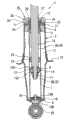
Fig. 1 is the axial section of the fluid-pressure shock absorber of the first mode of execution.
Fig. 2 is the planimetric map of the impact lid of the first mode of execution.
Fig. 3 be among Fig. 2 P-O-Q to view.
Fig. 4 is the axial section of the lid retainer of the first mode of execution.
Fig. 5 is the axial section of the fluid-pressure shock absorber major component of the second mode of execution.
Fig. 6 is the planimetric map of the impact lid of the second mode of execution.
Fig. 7 be among Fig. 6 P-O-Q to view.
Fig. 8 is the axial section of the fluid-pressure shock absorber major component of the 3rd mode of execution.
Fig. 9 is the planimetric map of the impact lid of the 3rd mode of execution.
Figure 10 be among Fig. 9 P-O-Q to view.
Figure 11 is the axial section of the fluid-pressure shock absorber major component of the 4th mode of execution.
Symbol description
The 1-fluid-pressure shock absorber, the 2-urceolus, 3-bar guiding element, 5-covers retainer, the 10-piston rod, 25-impacts lid, 32-end face (impacting the end of the guiding element side of lid), 34-holding part, 35-flanging part (caulking part), 37-evagination edge (lip part), 38-gap.
Embodiment
In the mode of execution of following record, as product, purpose is to improve desirable various viewpoint, its special problem is, even in the situation that described urceolus opening portion is riveted processing, the external diameter that impacts lid can not substantially exceed the urceolus external diameter yet, moreover, and also in order to solve other variety of issues.For example, be documented in the patent documentation 2 (Japanese kokai publication hei 6-58358 communique) as the technology of the opening portion that discloses urceolus with the fluid-pressure shock absorber of the fixed structure that impacts lid.In patent documentation 2 disclosed fluid-pressure shock absorbers, wait by welding and will impact all sides in the opening portion that lid is fixed on urceolus, be fixed in loam cake by being pressed into etc. will to impact to cover.Yet, rivet processing at the opening portion to urceolus, for example in the situation that inquire into crimping processing, the interior all sides that want loam cake is fixed on urceolus are difficult, the technology of avoiding impulsive load at urceolus of having to further inquire into, if can not avoid impact loading in the situation of urceolus, will consider that all impulsive loads are applied to the situation on the internal functional unit of the bottom valve 6 of fluid-pressure shock absorber or inner tube 7 etc., are necessary structure is inquired into.In the present embodiment, the following fluid-pressure shock absorber that impacts lid that has is represented and explanation, the structure of sealing even namely the opening portion riveted joint of urceolus is processed, also can make urceolus D outer diameter 0 become large, and can avoid impact loading in the fluid-pressure shock absorber of urceolus.
(the first mode of execution)
Based on Fig. 1~Fig. 4 the first mode of execution of the present invention is described.In addition, the fluid-pressure shock absorber 1 of the first mode of execution is the dual tube shock absorber (multi-cartridge fluid compression buffer) that is configured in the draft hitch between automotive wheel and the car body.
As shown in Figure 1, the fluid-pressure shock absorber 1 of the first mode of execution has the inside of the inner tube 7 of fluid (fluid a kind of) to be embedded with slidably piston 9 in inclosure.Inner tube 7 is divided on the oil cylinder chamber 8B under the chamber 8A and oil cylinder by piston 9 with inner grease chamber 8.Piston 9 is fixed on the underpart of piston rod 10 by nut 11.Piston rod 10 with forward end (upside of Fig. 1) slidably and can pass bar guiding element 3, the capsul 4 that is installed on inner tube 7 upper end portions airtight, liquid-tightly and be accommodated in the Sealing 12 that covers in the retainer 5 and extends to the outside of inner tube 7 and urceolus 2.In addition, chamber 8B is connected with apotheca 17 via bottom valve 6 under the oil cylinder.In addition, apotheca 17 inner inclosures fluid and gas are arranged.
In addition, be tubular as the Sealing 12 of seal arrangement of the present invention, interior all side sealings itself and live between the basic bar 10, and, the periphery side sealing its with lid retainer 5 between, thereby, seal the distolateral of urceolus 2.
Piston 9 is provided with and is communicated with on the oil cylinder tensile side path 13 and the compressed side path 14 of chamber 8B under the chamber 8A and oil cylinder.In the lower end surface of piston 9 (the downside end face of Fig. 1), be provided with the tensile side deamplification force generating 15A of mechanism that flows for restrained stretching side path 13 fluid, in the upper-end surface of piston 9 (the upside end face of Fig. 1), be provided with the mobile compressed side deamplification force generating 16A of mechanism of fluid for control compressed side path 14.In addition, the 15A of tensile side deamplification force generating mechanism and the compressed side deamplification force generating 16A of mechanism are made of throttle orifice and plate valve group (disk, vent disk, otch dish etc.).
Bottom valve 6 is provided with tensile side path 18 and the compressed side path 19 that is communicated with chamber 8B and apotheca 17 under the oil cylinder.In addition, bottom valve 6 is identical with piston 9, is provided with the tensile side deamplification force generating 15B of mechanism that flows for control fluid in tensile side path 18, is provided with the compressed side deamplification force generating 16B of mechanism in compressed side path 19.In addition, the tensile side deamplification force generating 15B of mechanism and the compressed side deamplification force generating 16B of mechanism also are made of throttle orifice and plate valve group (disk, vent disk, otch dish etc.).
In this fluid-pressure shock absorber 1, in the stretching stroke of piston rod 10, the fluid of apotheca 17 flows via tensile side path 18 chamber 8B under the oil cylinder, and the fluid of chamber 8A flows via tensile side path 13 chamber 8B under the oil cylinder on the oil cylinder.Thus, the 15A of tensile side deamplification force generating mechanism, 15B produce the tensile side damping force.In addition, in the compression stroke of piston rod 10, the fluid of chamber 8B flows to apotheca 17 via compressed side path 19 under the oil cylinder, and the fluid of chamber 8B flows via compressed side path 14 chamber 8A on the oil cylinder under the oil cylinder.Thus, the 16A of compressed side deamplification force generating mechanism, 16B produce the compressed side damping force.In addition, along with the volume-variation of the grease chamber that enters or withdraw from generation 8 of piston rod 10 relative grease chambeies 8 and cause the fluid profit and loss of this grease chamber 8, by the compensation of giving and accepting of the fluid between apotheca 17 and grease chamber 8 (the particularly chamber 8B under the oil cylinder).
Fluid-pressure shock absorber 1 is in the bottom (end of the opposite side of opening portion) of urceolus 2, be provided with the installing ring 20 (wheel side assembly department) that is connected usefulness with suspension arm, at the front end of piston rod 10, be provided with the assembly department (omitting among the figure) that is connected usefulness with car body.In this assembly department one side, be provided with impact when covering 25 collisional absorption piston rods and shorten with impact described later, have the impact rubber (omitting among the figure) that flexible resin consists of by urethane or rubber etc.This impact rubber also can be fixed on fluid-pressure shock absorber 1, can also be fixed on the automobile side that fluid-pressure shock absorber 1 is installed.Be provided for supporting the spring seat 22 of bearing spring at the outer side surface of urceolus 2.In addition, at the terminal side (downside of Fig. 1) of piston 10, in more detail, in the more forward end (upside of Fig. 1) of the piston 9 of terminal side, bounce-back stop member 23 and buffer 24 are set.In addition, fluid-pressure shock absorber 1 disposes to impact and covers 25 directly over the opening portion (Fig. 1 upper end part that comprises flanging part 35 described later) of urceolus 2.
As shown in Figure 3, it is synthetic resin members that the round-ended cylinder shape is arranged that impact covers 25, and 26 are formed with the bar inserting hole 27 that piston rod 10 can pass usefulness in the bottom.Cover 25 inside diameter 28 impacting, a plurality of (being the in the first embodiment 6) first rib 29 that extends towards axially (above-below direction among Fig. 3) equidistantly configures around axle O, that is to say, centers on axle O with 60 ° arranged spaced.Each first rib 29, one end (upper end portion among Fig. 3) arrives bottom 26, the inclined-plane 29a that (underpart of Fig. 3) arranges in the other end, the height of this inclined-plane 29a forms degressively towards the relative inside diameter 28 of end face 32 (ends of bar guiding element 3 sides).In addition, as shown in Figure 2, impact and cover 25 on bottom surface 31 (inner side surface of bottom 26), center on axle O and be furnished with second rib 30 from a plurality of (in the first embodiment as 6) of bar inserting hole 27 to radial direction take radiated entends with 60 ° interval etc.Further, on end face 32, be furnished with from the opening periphery of inside diameter 28 to outer diameter part 39 take a plurality of (in the first embodiment as the 6) groove 33 towards the radiated entends of radial direction with 60 ° interval etc. around axle O.Be equivalent to cylinder of the present invention section between inside diameter 28 and the outer diameter part described later 39.
As shown in Figure 4, lid retainer 5 has: with the holding part 34 of cylindric formation; In the upper formed convex edge 36 of the upper end portion of this holding part 34 periphery (the upper side end inner circumference edge among Fig. 4); And in the upper formed evagination edge 37 (lip part) of the underpart of this holding part 34 periphery (the downside end outer periphery among Fig. 4).As shown in Figure 1, lid retainer 5 be configured in capsul 4 directly over, and relatively piston rod 10 configures coaxially.In addition, opening portion (upper end portion among Fig. 1) to urceolus 2 carries out crimping processing (riveted joint processing), form the flat flanging part 35 (caulking part) of inward flange shape at this opening portion, thus, the evagination edge 37 of covering retainer 5 is clamped between flanging part 35 and the capsul 4.Thereby, making under holding part 34 state outstanding to the outside of urceolus 2, lid retainer 5 is fixed on the opening portion of urceolus 2.In addition, described Sealing 12 is kept by the convex edge 36 of lid retainer 5.At this, holding part 34 is covered 25 bulged-in impacts lids as impact and is pressed into section, and evagination edge 37 is as the riveted joint receiving portions.
In addition, in fluid-pressure shock absorber 1, cover the outer diameter part (outer cylinder face) that 25 inside diameter 28 is pressed into the holding part 34 of covering retainer 5 by impacting, and will impact each first rib 29 that covers 25 inside diameter 28 by the outer diameter part (outer cylinder face) of holding part 34 of lid retainer 5 and compress to radial direction, thus, cover 25 and produce combination force with covering between the retainer 5 impacting, namely, the power that relatively moves of generation restrictive axial and sense of rotation.Thus, can not keep impact to cover 25 by lid retainer 5 with relatively moving.So, in fluid-pressure shock absorber 1, cover 25 and approach when cover the upper end portion of retainer 5 making to impact, impact each inclined-plane 29a of the underpart of covering each first rib 29 of 25 and cover the upper end portion butt of the holding part 34 of retainer 5, thus, impact is covered 25 relative lid retainers 5 and is felt relieved.
In addition, as shown in Figure 1, in fluid-pressure shock absorber 1, cover 25 and be pressed into when finishing to covering retainer 5 impacting, namely, when impacting the outer side surface butt of the flanging part 35 cover 25 end face 32 and urceolus 2, cover between 25 the bottom surface 31, in the gap 38 that axial (above-below direction among Fig. 1) formation has prescribed distance with impacting at the upper-end surface 34a (with reference to Fig. 4) of the holding part 34 of lid retainer 5.
According to the first mode of execution, evagination edge 37 (lip part) thus, remains in the opening portion of urceolus 2 with flanging part 35 (caulking part) clamping of capsul 4 and urceolus 2 at the state lower cover retainer 5 that holding part 34 is given prominence to the outside of urceolus 2.The evagination edge 37 of radially extending thus, becomes the riveted joint receiving portion.So, cover the outer diameter part (outer cylinder face) that 25 inside diameter 28 is pressed into the holding part 34 of this lid retainer 5 with impacting, make impact cover 25 end face 32 (ends of bar guiding element 3 sides) and be close on the flanging part 35 of the opening portion that is formed at urceolus 2.Therefore, even the opening portion of urceolus 2 is carried out crimping processing (riveted joint processing) and the fluid-pressure shock absorber 1 of sealing, can equate with the external diameter of urceolus 2 having or configure (maintenance) at the opening portion of this urceolus 2 less than the impact lid 25 of the outer diameter part 39 of this external diameter.
Shown in patent documentation 2, so long as the structure by the fixed cover such as welding and urceolus, just impulsive load can be transmitted in the mode of impacting lid → loam cake → urceolus, but, because will not cover retainer in the present embodiment structure is fixed on axially, therefore, need to manage impulsive load is delivered to urceolus.
According to the first mode of execution; because under the state that impacts flanging part 35 butts cover 25 end face 32 and urceolus 2; upper-end surface 34a in the holding part 34 of lid retainer 5 covers between 25 the bottom surface 31 with impact; axially forming the gap 38 with spacing; therefore; even cover in the situation of the impulsive load that input ratio is larger on 25 in impact, owing to can avoid this impact loading in urceolus 2, thus can protect the internal functional unit of fluid-pressure shock absorber 1.Further, owing to cover 25 bottom 26 inner side surfaces (bottom surface 31) and dispose second rib 30 impacting, therefore, also can guarantee to impact and cover 25 rigidity own.
According to the first mode of execution, cover 25 and be pressed into and cover retainer 5 by impacting, impact the outer diameter part (outer cylinder face) that the first rib 29 that cover on 25 the inside diameter 28 passes through to cover the holding part 34 of retainer 5 and compress to radial direction being configured in.Thus, impact cover 25 with lid retainer 5 between produce combination force, that is to say, produce the power that relatively moves of restrictive axial and sense of rotation, therefore, can not keep impact to cover 25 by covering retainer 5 with relatively moving.
According to the first mode of execution, cover 25 and be pressed into when covering retainer 5 will impacting, cover 25 and approach when cover retainer 5 when impacting, impact formed inclined-plane 29a on the wedge-type shape underpart of covering each first rib 29 of 25 and cover the holding part 34 upper end portion butts of retainer 5.Therefore, make to impact and cover 25 relative lid retainers 5 and feeling relieved, can at an easy rate impact be covered 25 and be pressed into and cover retainer 5.Therefore, can improve impact and cover 25 assembling operation efficient.
According to the first mode of execution, owing to the end face 32 (bar guiding element 3 side ends) that covers 25 in impact forms a plurality of grooves 33 that are communicated with inside diameter 28 and outer diameter part 39, therefore, be trapped in invaders such as impacting rainwater cover 25 inboards, dust and can cover 25 outside discharge to impacting by this groove 33.
In addition, in the first embodiment, as the fluid-pressure shock absorber of the urceolus opening portion being riveted processing, enumerated and to have impacted the impulsive load that is subject to of lid and pass to urceolus and can make the maximized structure of urceolus diameter, but, not needing to solve any two problems, for example also can be to impact the diameter of lid greater than the diameter of urceolus.
(the second mode of execution)
Below, based on Fig. 5~Fig. 7 the second mode of execution of the present invention is described.At this, consist of identical structure with the first mode of execution, apply same title and symbol, simultaneously, for the sake of simplicity record of specification has been omitted its detailed description.In addition, in the second mode of execution, only have and impact that cover 41 structure different from the first mode of execution (impact covers 25).
As shown in Figure 7, impact and cover 41 and engage (for example welding) with the bottom 42 of the drawing product that the round-ended cylinder shape is arranged by the plate 43 that will be used for supporting installation rubber (figure omits) and form, in the bottom 42 and plate 43 be formed for the bar inserting hole 44 that piston rod 10 passes.
As shown in Figure 6, impact and cover 41 in cylinder section 45, a plurality of (being in the present embodiment 5) the 3rd rib 46 that extends towards axially (above-below direction among Fig. 7) around axle O with 60 ° interval and therefore equidistantly configuration, forms petal shape on the axle vertical cross-section of cylinder section 45.In addition, impact and to cover 41 and be formed with lip part 47 at the underpart of cylinder section 45 periphery.In addition, each the 3rd rib 46 makes a section 45 towards extending axially and crooked with the boundary part of lip part 47 in cylinder section 45, and make lip part 47 towards radial direction with radiated entends.
As shown in Figure 5, in the second mode of execution, cover 41 and be pressed into the holding part 34 (with reference to Fig. 4) of covering retainer 5 with the forms that cover by impacting, thus, produce combination force impacting between the holding part 34 cover 41 cylinder section 45 and to cover retainer 5, namely, the power that relatively moves of generation restrictive axial and sense of rotation.Thus, can not keep impact to cover 41 by lid retainer 5 with relatively moving.In addition, in the second mode of execution, cover 41 and approach when cover the upper end portion of retainer 5 when impacting, to impact 41 the cylinder section 45 of cover and the R shape between the lip part 47 and cover the upper end portion butt of retainer 5, inboard from 41 cylinder section 45 to impact that the holding part 34 of covering retainer 5 is covered guides.
In addition, as shown in Figure 5, in the second mode of execution, impacting outer side surface butt cover 41 lip part 47 and the flanging part 35 of urceolus 2, impacting and cover 41 to covering being pressed on the retainer 5 when finishing, cover between 41 the bottom 42, in the gap 38 that axial (above-below direction among Fig. 5) formation has prescribed distance with impacting at the upper-end surface 34a (with reference to Fig. 4) of the holding part 34 of lid retainer 5.
According to the second mode of execution, can obtain the effect identical with described the first mode of execution.In addition, be trapped in each the 3rd rib 46 by being formed at lip part 47 such as the invaders that impact rainwater cover 41 inboards, dust and cover 41 outside discharge to impacting.
(the 3rd mode of execution)
Below, based on Fig. 8~Figure 10 the 3rd mode of execution of the present invention is described.At this, consist of identical structure with the first mode of execution, apply identical title and symbol, simultaneously, for the sake of simplicity record of specification has been omitted its detailed description.
Such as Fig. 9 and shown in Figure 10, impact and cover 51 and have the engagement portion 52 of the hook shape of snap-latch surface 52a in the formation of the underpart of each first rib 29.Each engagement portion 52 forms to extending near the direction of axle O by the inclined-plane 29a that makes each first rib 29, and inclined-plane 29a and snap-latch surface 52a configure so that rib section is carried out the acutangulate mode of chamfering structure.
In the 3rd mode of execution, as shown in Figure 8, cover the outer diameter part (outer cylinder face) that 51 inside diameter 28 is pressed into the holding part 34 of covering retainer 5 by impacting, and will impact each first rib 29 that covers 51 inside diameter 28 by the outer diameter part (outer cylinder face) of holding part 34 of lid retainer 5 and compress to radial direction, cover 51 and produce combination force with covering between the retainer 5 impacting, namely, the power that relatively moves of generation restrictive axial and sense of rotation.Thus, can not keep impact to cover 51 by lid retainer 5 with relatively moving.In addition, in the 3rd mode of execution, impacting under state cover 51 end face 32 and the outer side surface butt of the flanging part 35 of urceolus 2, impacting each engagement portion 52 (clamping close device) of covering each first rib 29 of 51 and engage with the formed ring-type engagement grooves 53 of holding part 34 outer circumferential faces (clamping close device) that cover retainer 5.This engagement portion 52 and engagement groove 53 usefulness are concavo-convex to be engaged also passablely, can also cover 51 1 sides and groove is set, protuberance is set covering retainer 5 impacting, and carries out the concavo-convex engaging opposite with described mode of execution.
In addition, in the 3rd mode of execution, identical with described the first mode of execution, also under the state of the outer side surface butt that impacts the flanging part 35 cover 51 end face 32 and urceolus 2, cover between 51 the bottom surface 31, in the gap 38 that axial (above-below direction among Fig. 5) formation has prescribed distance with impacting at the upper-end surface 34a (with reference to Fig. 4) of the holding part 34 of lid retainer 5.
According to the 3rd mode of execution, can obtain the effect identical with described the first mode of execution.Further, according to the 3rd mode of execution, even for example impacting the axial length cover each first rib 29 of 51 is restricted, can not guarantee by only compressing each first rib 29 in the situation of the punching press load stipulated, owing to impacting and cover each engagement portion 52 (clamping close device) of 51 and engage with the engagement groove 53 (clamping close device) that covers retainer 5, can guarantee the punching press load of stipulating.
At this, by impact cover 51 with the engagement portion of lid retainer 5, will cover 51 impulsive loads of inputting and be applied on the internal functional unit via covering retainer 5 to impacting, but, because the little engagement portion of the impact that resin is made lid 51 can be out of shape, so most of power is born by the end of urceolus.
In addition, according to the 3rd mode of execution, represented following structure, namely, cover 51 and be pressed into the confining force that covers on the retainer 5 by impacting, impact the confining force that engages generation cover each engagement portion 52 (clamping close device) of 51 and the engagement groove 53 (clamping close device) that covers retainer 5 by making, guarantee the punching press load stipulated, but, as long as only can cover each engagement portion 52 (clamping close device) of 51 and guarantee punching press load with the confining force that engages generation of the engagement groove 53 (clamping close device) of lid retainer 5 by making to impact, leave no choice but that not necessarily impact is covered 51 and be pressed into and cover retainer 5.
(the 4th mode of execution)
Below, based on Figure 11 the 4th mode of execution of the present invention is described.At this, consist of identical structure with first, second mode of execution, also apply same title and symbol, simultaneously, for the sake of simplicity record of specification has been omitted its detailed description.
The 4th mode of execution is with respect to the second mode of execution, and its difference is the outer circumference end of its lip part 47 is made tubular extending portion 60 towards axial urceolus lateral bend.Utilize this extending portion 60, can prevent from that dust etc. from invading to impact from lip part 47 cover 41 and cover between the retainer 5.
In addition, each above-mentioned mode of execution is not limited to the content of above-mentioned restriction, for example also can adopt following structure.
At each above-mentioned mode of execution, although take the multi-cartridge fluid compression buffer as object,, such as also can take single-cylinder type fluid-pressure shock absorber, automatic pumping formula fluid-pressure shock absorber etc. arbitrarily fluid-pressure shock absorber as object.
In addition, in each above-mentioned mode of execution, although will impact the lid make circular,, for example also can make the polygonal ring-type.In addition, the lid retainer also can be made C word shape so long as sealing configuration impacts lid.
In addition, in each above-mentioned mode of execution, although be illustrated as an example of the flanging part 35 that the whole circumference as the distolateral caulking part of urceolus 2 one carried out crimping example, but, be not limited to this, also can in the part at a plurality of positions, rivet at the riveting portion of internal side diameter.In this case, impact lid and the part butt of not riveting.
Claims (8)
1. fluid-pressure shock absorber, comprising: an end has the urceolus of opening portion; The piston rod that front end is given prominence to the outside of this urceolus from the opening portion of described urceolus; And the bar guiding element that is configured in described urceolus opening portion, by described urceolus opening portion is carried out all-round riveted joint to the inside flat flanging part is set, opening portion sealing with described urceolus, it is characterized in that, described fluid-pressure shock absorber comprises: have the cylinder section of relatively described urceolus arranged coaxial and the impact lid of bottom; And the lid retainer that keeps described impact lid, described lid retainer by the riveted joint receiving portion of radially extending and the described impact lid of restriction to axially relatively moving and forming tubular and consist of in the holding part that outer diameter part is pressed into the cylinder section of described impact lid, opening portion side end face and the described flat flanging part butt of the cylinder section of described impact lid, between the bottom of the upper-end surface of the described holding part of described lid retainer and described impact lid, axially forming the gap with spacing.
2. fluid-pressure shock absorber as claimed in claim 1 is characterized in that, described impact lid is for described urceolus equal diameters or less than the cylindrical shape of described urceolus diameter.
3. fluid-pressure shock absorber as claimed in claim 1 is characterized in that, is provided with clamping close device, and this clamping close device makes that described impact lid and described lid retainer are mutual concavo-convexly to be engaged, and limits described impact lid and described lid retainer to axial relatively moving.
4. fluid-pressure shock absorber as claimed in claim 2 is characterized in that, is provided with clamping close device, and this clamping close device makes that described impact lid and described lid retainer are mutual concavo-convexly to be engaged, and limits described impact lid and described lid retainer to axial relatively moving.
5. fluid-pressure shock absorber as claimed in claim 1 is characterized in that, is provided with the distolateral seal arrangement that seals to described urceolus in described lid retainer.
6. fluid-pressure shock absorber as claimed in claim 2 is characterized in that, is provided with the distolateral seal arrangement that seals to described urceolus in described lid retainer.
7. fluid-pressure shock absorber as claimed in claim 3 is characterized in that, is provided with the distolateral seal arrangement that seals to described urceolus in described lid retainer.
8. fluid-pressure shock absorber as claimed in claim 4 is characterized in that, is provided with the distolateral seal arrangement that seals to described urceolus in described lid retainer.
Applications Claiming Priority (4)
| Application Number | Priority Date | Filing Date | Title |
|---|---|---|---|
| JP021500/08 | 2008-01-31 | ||
| JP2008021500 | 2008-01-31 | ||
| JP2008330336A JP5206965B2 (en) | 2008-01-31 | 2008-12-25 | Fluid pressure buffer |
| JP330336/08 | 2008-12-25 |
Publications (2)
| Publication Number | Publication Date |
|---|---|
| CN101514733A CN101514733A (en) | 2009-08-26 |
| CN101514733B true CN101514733B (en) | 2013-01-02 |
Family
ID=40930585
Family Applications (1)
| Application Number | Title | Priority Date | Filing Date |
|---|---|---|---|
| CN2009101307459A Active CN101514733B (en) | 2008-01-31 | 2009-01-23 | Fluid-pressure shock absorber |
Country Status (4)
| Country | Link |
|---|---|
| US (1) | US7810619B2 (en) |
| JP (1) | JP5206965B2 (en) |
| KR (1) | KR101516824B1 (en) |
| CN (1) | CN101514733B (en) |
Families Citing this family (19)
| Publication number | Priority date | Publication date | Assignee | Title |
|---|---|---|---|---|
| JP5773805B2 (en) * | 2011-08-30 | 2015-09-02 | 株式会社東芝 | Washing machine |
| KR101337583B1 (en) | 2011-12-12 | 2013-12-06 | 주식회사 만도 | Dust seal structure for shock absorber |
| US9909639B2 (en) * | 2013-06-28 | 2018-03-06 | Smc Corporation | Low-dust/dust-resistant shock absorber |
| JP5799069B2 (en) * | 2013-10-08 | 2015-10-21 | カヤバ工業株式会社 | Shock absorber |
| KR102152024B1 (en) * | 2014-01-03 | 2020-09-04 | 주식회사 만도 | Shock absorber |
| DE102014224636A1 (en) * | 2014-12-02 | 2016-06-02 | Zf Friedrichshafen Ag | End cap for a piston-cylinder unit |
| CN104494388A (en) * | 2014-12-12 | 2015-04-08 | 重庆长安汽车股份有限公司 | Dustproof blocking cap for front supporting column assembly |
| KR101662225B1 (en) * | 2015-03-06 | 2016-10-04 | 주식회사 만도 | Shock absorber |
| US10072723B2 (en) * | 2015-04-24 | 2018-09-11 | Beijingwest Industries Co., Ltd. | Closing assembly for a magneto-rheological damper |
| JP6616672B2 (en) * | 2015-11-20 | 2019-12-04 | Kyb株式会社 | Bump stopper and shock absorber |
| JP6817731B2 (en) * | 2016-06-30 | 2021-01-20 | Kyb株式会社 | Cylinder member and shock absorber |
| US11383571B2 (en) * | 2017-01-09 | 2022-07-12 | Ford Global Technologies, Llc | Shock absorbers having internal jounce control |
| GB2566332B (en) * | 2017-09-12 | 2019-12-11 | Metrol Springs Ltd | Seal housing |
| US10816055B2 (en) | 2018-04-27 | 2020-10-27 | Tenneco Automotive Operating Company Inc. | Damper bumper cap with labyrinth air passageway |
| US11009095B2 (en) * | 2018-11-06 | 2021-05-18 | Tenneco Automotive Operating Company Inc. | Damper with monolithic base |
| CN110005746B (en) * | 2019-04-18 | 2020-12-15 | 嘉兴宸轩管件制造科技有限公司 | Hydraulic connecting plate of automobile shock absorber |
| US11566679B2 (en) * | 2020-11-03 | 2023-01-31 | DRiV Automotive Inc. | Bumper cap for damper |
| KR102309703B1 (en) | 2021-01-11 | 2021-10-07 | 장요한 | Shock absorber for vehicles |
| KR102566882B1 (en) | 2022-03-10 | 2023-08-16 | 부성테크 주식회사 | Manufacturing method of holder assembly using laser welding |
Citations (5)
| Publication number | Priority date | Publication date | Assignee | Title |
|---|---|---|---|---|
| US5115892A (en) * | 1988-09-27 | 1992-05-26 | Atsugi Unisia Corporation | Hydraulic shock absorber with piston seal structure for enhancement of initial response |
| US5224573A (en) * | 1990-06-27 | 1993-07-06 | Atsugi Unisia Corporation | Hydraulic damper |
| EP0658701A1 (en) * | 1993-12-18 | 1995-06-21 | August Bilstein GmbH & Co. KG | Hydraulic damper for vehicles |
| US6659243B2 (en) * | 2001-08-02 | 2003-12-09 | Showa Corporation | Shaft seat part structure of hydraulic shock absorber and assembling method thereof |
| CN200978909Y (en) * | 2006-11-23 | 2007-11-21 | 柳平波 | Vibration damper with built-in buffer spring structure |
Family Cites Families (8)
| Publication number | Priority date | Publication date | Assignee | Title |
|---|---|---|---|---|
| JPS411859Y1 (en) * | 1964-01-29 | 1966-02-10 | ||
| JPH0482442U (en) * | 1990-11-28 | 1992-07-17 | ||
| JPH0658358A (en) * | 1992-08-05 | 1994-03-01 | Tokico Ltd | Hydraulic buffer |
| JP3000694U (en) * | 1994-02-02 | 1994-08-09 | 株式会社荒井製作所 | Oil seal device for hydraulic shock absorber |
| JP3886064B2 (en) * | 1996-11-05 | 2007-02-28 | カヤバ工業株式会社 | Bump stopper structure |
| JP4455728B2 (en) * | 2000-04-28 | 2010-04-21 | 日立オートモティブシステムズ株式会社 | Hydraulic shock absorber |
| US20060219506A1 (en) * | 2005-03-31 | 2006-10-05 | Zdeb David T | Shock absorber including supplemental friction generating device |
| JP2007057088A (en) | 2005-07-29 | 2007-03-08 | Hitachi Ltd | Cylinder device |
-
2008
- 2008-12-25 JP JP2008330336A patent/JP5206965B2/en active Active
-
2009
- 2009-01-23 CN CN2009101307459A patent/CN101514733B/en active Active
- 2009-01-28 US US12/320,507 patent/US7810619B2/en active Active
- 2009-01-29 KR KR1020090006770A patent/KR101516824B1/en active IP Right Grant
Patent Citations (5)
| Publication number | Priority date | Publication date | Assignee | Title |
|---|---|---|---|---|
| US5115892A (en) * | 1988-09-27 | 1992-05-26 | Atsugi Unisia Corporation | Hydraulic shock absorber with piston seal structure for enhancement of initial response |
| US5224573A (en) * | 1990-06-27 | 1993-07-06 | Atsugi Unisia Corporation | Hydraulic damper |
| EP0658701A1 (en) * | 1993-12-18 | 1995-06-21 | August Bilstein GmbH & Co. KG | Hydraulic damper for vehicles |
| US6659243B2 (en) * | 2001-08-02 | 2003-12-09 | Showa Corporation | Shaft seat part structure of hydraulic shock absorber and assembling method thereof |
| CN200978909Y (en) * | 2006-11-23 | 2007-11-21 | 柳平波 | Vibration damper with built-in buffer spring structure |
Also Published As
| Publication number | Publication date |
|---|---|
| JP2009204158A (en) | 2009-09-10 |
| KR20090084702A (en) | 2009-08-05 |
| CN101514733A (en) | 2009-08-26 |
| US7810619B2 (en) | 2010-10-12 |
| KR101516824B1 (en) | 2015-04-30 |
| US20090194379A1 (en) | 2009-08-06 |
| JP5206965B2 (en) | 2013-06-12 |
Similar Documents
| Publication | Publication Date | Title |
|---|---|---|
| CN101514733B (en) | Fluid-pressure shock absorber | |
| EP1959173B1 (en) | Sealing device | |
| US8240642B2 (en) | Fluid damper with internal compression spring | |
| CN104565172A (en) | Cylinder device and manufacturing method therefor | |
| CN106233026B (en) | Buffer device | |
| WO2015178285A1 (en) | Shock absorber | |
| KR20180091875A (en) | Automotive vibration damper | |
| US9599184B2 (en) | Fluid damper assembly having a multi-functional bushing | |
| US5533598A (en) | Hydraulic shock absorber for motor vehicles | |
| CN105102253A (en) | Fixing structure of shift cable | |
| US7621383B2 (en) | Double tube hydraulic shock absorber | |
| WO2015178287A1 (en) | Shock absorber | |
| EP3009707B1 (en) | Air spring piston with integrated sealing | |
| JP4491818B2 (en) | Single cylinder type shock absorber | |
| US10253840B2 (en) | Cylinder apparatus | |
| JP6378963B2 (en) | Shock absorber | |
| KR101756419B1 (en) | Dust seal assembly structure for shock absorber | |
| KR102244876B1 (en) | Method for fastening a rebound stop to a piston rod of a vibration damper | |
| CN112119239B (en) | Vibration damper with adjustable damping valve | |
| WO2013145261A1 (en) | Damper for vehicle | |
| JP2014029175A (en) | Fluid pressure shock absorber | |
| CN103791019B (en) | Amortisseur | |
| KR101705828B1 (en) | Cylinder cap sealing structure for shock absorbers | |
| WO2017090476A1 (en) | Cylinder device | |
| CN202500949U (en) | Oil seal director assembly of shock absorber |
Legal Events
| Date | Code | Title | Description |
|---|---|---|---|
| C06 | Publication | ||
| PB01 | Publication | ||
| C10 | Entry into substantive examination | ||
| SE01 | Entry into force of request for substantive examination | ||
| C14 | Grant of patent or utility model | ||
| GR01 | Patent grant |