EP0777400A2 - Personal beam cellular communication system - Google Patents
Personal beam cellular communication system Download PDFInfo
- Publication number
- EP0777400A2 EP0777400A2 EP96113313A EP96113313A EP0777400A2 EP 0777400 A2 EP0777400 A2 EP 0777400A2 EP 96113313 A EP96113313 A EP 96113313A EP 96113313 A EP96113313 A EP 96113313A EP 0777400 A2 EP0777400 A2 EP 0777400A2
- Authority
- EP
- European Patent Office
- Prior art keywords
- communication system
- user
- beams
- users
- cellular communication
- Prior art date
- Legal status (The legal status is an assumption and is not a legal conclusion. Google has not performed a legal analysis and makes no representation as to the accuracy of the status listed.)
- Withdrawn
Links
Images


Classifications
-
- H—ELECTRICITY
- H01—ELECTRIC ELEMENTS
- H01Q—ANTENNAS, i.e. RADIO AERIALS
- H01Q3/00—Arrangements for changing or varying the orientation or the shape of the directional pattern of the waves radiated from an antenna or antenna system
- H01Q3/26—Arrangements for changing or varying the orientation or the shape of the directional pattern of the waves radiated from an antenna or antenna system varying the relative phase or relative amplitude of energisation between two or more active radiating elements; varying the distribution of energy across a radiating aperture
- H01Q3/30—Arrangements for changing or varying the orientation or the shape of the directional pattern of the waves radiated from an antenna or antenna system varying the relative phase or relative amplitude of energisation between two or more active radiating elements; varying the distribution of energy across a radiating aperture varying the relative phase between the radiating elements of an array
-
- H—ELECTRICITY
- H04—ELECTRIC COMMUNICATION TECHNIQUE
- H04W—WIRELESS COMMUNICATION NETWORKS
- H04W16/00—Network planning, e.g. coverage or traffic planning tools; Network deployment, e.g. resource partitioning or cells structures
- H04W16/24—Cell structures
- H04W16/28—Cell structures using beam steering
-
- H—ELECTRICITY
- H04—ELECTRIC COMMUNICATION TECHNIQUE
- H04B—TRANSMISSION
- H04B7/00—Radio transmission systems, i.e. using radiation field
- H04B7/02—Diversity systems; Multi-antenna system, i.e. transmission or reception using multiple antennas
- H04B7/04—Diversity systems; Multi-antenna system, i.e. transmission or reception using multiple antennas using two or more spaced independent antennas
Definitions
- This invention relates generally to a cellular communication system, and more particularly, to a cellular communication system utilizing a phased array antenna in conjunction with a spread spectrum communications method which includes code division multiple access techniques for generating a plurality of highly directive adjustable or fixed personalized communication beams that provide signal coverage to system users throughout an original geographical cell.
- each of a cellular communication system's original geographical cells employ a base station with an antenna that provides signal coverage throughout a given original cell.
- Such base stations commonly include an omnidirectional antenna that provides signal coverage throughout the entire original cell or a sectorized antenna that divides the cell into a number of signal coverage sectors.
- a corresponding number of additional base stations with antennas are required to provide signal coverage within the boundaries of the additional cells.
- the cost of the cellular communication system is increased due to the increased hardware costs.
- Fig. 1 illustrates a conventional cellular communication system's original geographical cell 10 that has been split into numerous smaller geographical cells 12 .
- the original cell 10 may have originally included a single base station 14 located at a center location which is now illustrated as providing signal coverage for one of the smaller cells 12 .
- Each of the smaller cells 12 includes an additional base station 16 and an accompanying antenna for providing signal coverage for users located within each of the smaller cells 12 .
- the addition of the smaller cells 12 increases the costs of providing signal coverage for the users located in the geographical area previously associated with the original geographical cell 10 .
- a cellular communication system having increased user capacity without requiring "cell splitting" and the additional costs associated therewith.
- a cellular communication system that utilizes a phased array antenna and user tracking assemblies for transmitting highly directive adjustable or fixed personalized communication beams representing user signals in the directions of each of the system users located within an original geographical cell.
- a cellular communication system for transmitting highly directive personalized communication beams to system users located within an original geographical cell of the cellular communication system.
- Each of the personalized communication beams represents user signals assigned to specific users located within the original geographical cell.
- a phased array antenna is positioned within the original geographical cell for transmitting and receiving personalized communication beams that are adjustable in the directions of each of the users within the cell.
- a digital beam forming apparatus feeds the phased array antenna with user signals that form the adjustable personalized communication beams which are transmitted in the individual directions of the system users located within the geographical cell.
- the digital beam forming apparatus also receives the user signals received by the phased array antenna.
- a user tracking apparatus provides the digital beam forming apparatus with tracking information regarding the relative amplitudes of the user signals such that the digital beam forming apparatus adjusts each of the user signals to substantially center each of the adjustable personalized communication beams about one of the system users.
- an omnidirectional antenna is positioned in close proximity to a center location of the geographical cell for transmitting and receiving an omnidirectional communication beam in the directions of the system users traveling within a predetermined range of the center location.
- a phased array antenna is positioned within the geographical cell for transmitting and receiving a fixed number of personalized communication beams in fixed directions such that signal coverage is provided throughout the geographical cell.
- a plurality of digital beam forming networks feed the phased array antenna with user signals that form the fixed personalized communication beams.
- the plurality of digital beam forming networks also receive the user signals received by the phased array antenna.
- a plurality of modulating/demodulating networks corresponding to at least the number of the users within the geographical cell modulate and demodulate the user signals assigned to each of the particular users.
- a switching network switches the plurality of modulating/demodulating networks between the plurality of digital beam forming networks such that each of the system users is assigned to one of the fixed personalized communication beams providing maximum signal coverage with respect to each of the user's locations.
- a user tracking apparatus tracks each user and provides the switching network with tracking information regarding the amplitudes of the user signals represented by the communication beams.
- FIG. 2 illustrates a phased array antenna 18 that may be used in conjunction with the cellular communication system of the present invention.
- the phased array antenna 18 includes a plurality of radiating elements 20 which are positioned about a circle 22 having a radius(r) of approximately ten feet. This configuration includes one hundred and twenty of the radiating elements 20 each of which are separated by a distance(d) of approximately six inches. It should be noted that phased array antennas having a different number of radiating elements and different physical configurations may be used in conjunction with the cellular communication system of the present invention.
- the phased array antenna 18 is configured for transmitting a large number of highly directive adjustable or fixed electromagnetic beams of radiation for communication purposes.
- Each of the communication beams has a beam width of approximately three degrees allowing each of the beams to be substantially centered about an individual user of the system.
- the high directivity of the communication beams allows each of the beams to be personalized for each user within a cell of the system.
- the communication beams are personalized through the use of well known cellular signaling methods such as a spread spectrum communication method which includes code division multiple access (CDMA) techniques wherein a particular user is assigned to a spread spectrum code and a carrier frequency which are retained throughout a cell of the system.
- CDMA code division multiple access
- Fig. 3 illustrates the phased array antenna 18 mounted to an existing base station located at a center location 24 of an original geographical cell 26 of the cellular communication system.
- the phased array antenna 18 transmits adjustable personalized communication beams 28 representing user signals in the individual directions of each of the users located within the cell 26 .
- adjustable personalized communication beams 28 representing user signals in the individual directions of each of the users located within the cell 26 .
- an omnidirectional antenna as illustrated in Fig. 8 , may be positioned in close proximity to the center location 24 for transmitting an omnidirectional communication beam to users traveling within approximately one half of a mile of the center location 24 as illustrated by a circle 30 .
- the use of the omnidirectional communication beam reduces or eliminates the problem of dropped calls for users which are moving rapidly throughout the area illustrated by the circle 30 .
- the phased array antenna 18 may also be applied in a "green field" area, i.e. a geographical area which is not presently serviced by a cellular communication system, thereby extending the range and area covered by a newly created cell in such an area while requiring fewer base stations.
- a green field area i.e. a geographical area which is not presently serviced by a cellular communication system
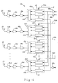
- FIGS. 4 and 5 respectively illustrate representative portions of a transmitting network 34 and a receiving network 36 of the cellular communication system. Both the transmitting network 34 and the receiving network 36 are coupled to the radiating elements 20 of the phased array antenna 18 . As previously discussed, the phased array antenna 18 is located at the center location 24 of the cell 26 of the cellular communication system. For purposes of simplification, only four of the one hundred and twenty radiating elements 20 are illustrated in FIG. 4 , and three of the radiating elements 20 are illustrated in FIG. 5 . The phased array antenna 18 is used in conjunction with the transmitting network 34 to transmit and adjust the direction of the personalized communication beams 28 representing user signals in the individual directions of each of the users within the cell 26 .
- the representative portion of the transmitting network 34 is illustrated including signal modulators 38a - 38c that modulate three user signals that may be received a telephone network (not shown).
- the transmitting network 34 may receive user signals from another base station in the cellular communication system via land based communication lines or additional receivers located within the base station. Such sources of user signals represent other subscribers within the cellular communication system communicating to a particular user.
- the total number of signal modulators for the transmitting network 34 corresponds to at least the number of system users located within the cell 26 . As such, each user is assigned to a unique user signal and one of the personalized communication beams 28 that is retained throughout the entire cell 26 .
- the signal modulators 38a - 38c advantageously utilize a spread spectrum communication method which includes code division multiple access (CDMA) techniques to increase the number of users that can be accommodated within the allocated frequency spectrum of cell 26 and the cellular communication system.
- CDMA code division multiple access
- Each of the users within the cell 26 is assigned to a carrier frequency and a code assignment which are retained throughout the cell. Therefore, the problems typically associated with cellular communications systems utilizing "microcells" including, but not limited to, increased “handovers", irregular user signal strengths and interference are substantially eliminated.
- the implementation of CDMA techniques in conjunction with the highly efficient personalized communication beams reduces the transmit power requirements which increases the battery life of user handsets.
- the transmitting network 34 is illustrated further including transmitting digital beam forming networks 40a - 40d that each include variable amplitude and phase control elements 42 for synthesizing a desired antenna beam shape from the modulated user signals received from each of the signal modulators 38a - 38c .
- the total number of transmitting digital beam forming networks represented by networks 40a - 40d corresponds to the number of radiating elements 20 in the phased array antenna 18 .
- Each of the transmitting digital beam forming networks 40a - 40d is illustrated including three variable amplitude and phase control elements 42 , each corresponding to one of the signal modulators 38a - 38c .
- the total of number of variable amplitude and phase control elements 42 in each of the transmitting digital beam forming networks corresponds to the total number signal modulators and, in turn, at least the number of users within the cell 26 .
- Each of the variable amplitude and phase control elements 42 are adjusted to change the relative amplitudes and phases of the modulated user signals such that the personalized communication beams are substantially centered about the individual system users.
- Combiners 44a - 44d combine the signals received from the amplitude and phase control elements 42 and output synthesized user signals. Each of the synthesized user signals are fed to digital to analog converters 46a - 46d , band pass filters 48a - 48d , and power amplifiers 50a - 50d .
- the radiating elements 20 transmit the adjustable personalized communication beams 28 , representing the modulated signals from the signal modulators 38a - 38c , in the individual directions of specific users within the cell 26 .
- Each of the transmitting digital beam forming networks 40a - 40d receive tracking information regarding each of the system users about input lines 52a - 52d . This information is used to adjust the amplitude and phase control elements 42 such that the shapes and directions of the personalized communication beams 28 transmitted from each of the radiating elements 20 are adjusted as the system users move throughout the cell 26 .
- the representative portion of the receiving network 36 is illustrated including four receiving beam forming networks 60a - 60d that receive the user signals from the radiating elements 20 of the phased array antenna 18 .
- the user signals are amplified and converted to digital signals by the combined preamplifier and analog to digital converter networks 56a - 56c .
- the total number of receiving beam forming networks represented by networks 60a - 60d corresponds to at least the number of system users located within the cell 26 .
- Each of the receiving digital beam forming networks 60a - 60d is illustrated including three variable amplitude and phase control elements 62 corresponding to the radiating elements 20 for synthesizing desired antenna beam shapes from the received user signals.
- the total number of the variable amplitude and phase control elements 62 for each of the receiving beam forming networks 60a - 60c corresponds to the total number of the radiating elements 20 in the phase array antenna 18 .
- Combiners 64a - 64d combine the signals received from the variable amplitude and phase control elements 62 such that each of the receiving digital beam forming networks 60a - 60d outputs a synthesized user signal.
- Switching networks 66a - 66d feed the synthesized user signals to demodulators 68a - 68d .
- the total number of demodulators corresponds to at least the number of users within the cell 26 of the cellular communication system. Therefore, each of the demodulators 68a - 68d demodulates a synthesized user signal from a corresponding beam forming network and outputs a desired user signal assigned to a particularly user within the cellular cell 26 .
- the demodulators 68a - 68d employ a spread spectrum communication method including CDMA techniques.
- the receiving network 36 is coupled to user tracking assemblies that track each of the users located within the cell 26 according to user signal power ratios with respect to adjacent communication beams 28 .
- the user tracking assemblies provide the receiving and transmitting beam forming networks 60a - 60d and 40a - 40d with tracking signals for adjusting the transmitting directions of the communication beams 28 in the directions of each of the system users.
- Each of the transmitting beam forming networks 60a - 60d and the demodulators 68a - 68d are coupled to user tracking assemblies as represented by user tracking assembly 70b . The operation of the user tracking assemblies of the system will be described with reference to the user tracking assembly 70b .
- the representative user tracking assembly 70b is illustrated coupled to beam forming network 60b and the demodulator 68b .
- the user tracking assembly 70b includes an amplitude comparator 72b and microprocessors 76b and 78b .
- the relative amplitudes of the user signal as represented by the adjacent communication beams of beam forming networks 60a and 60c are compared with the amplitude of the user signal as represented by the communication beam from beam forming network 60b .
- the switching network 66b samples the synthesized user signals outputted by the receiving digital beam forming networks 60a - 60c and serially feeds the respective signals to the demodulator 68b .
- the demodulator 68b demodulates the particular user signal from the sampled synthesized signals and the amplitude comparator 72b compares the relative amplitudes of the particular user signals.
- the comparator 72b also outputs the desired user signal to the telephone network (not shown) about line 74b .
- the microprocessors 76b and 78b determine the power ratios of the user signal for the respective communication beams using conventional signal processing techniques. The distance and angle that a particular user is away from a beam's center may be determined from the power ratios.
- Tracking signals are provided to the receiving digital beam forming network 60b and the transmitting digital beam forming network 40b using lines 80b and 52b . In the same fashion, the other receiving and transmitting beam forming networks receive tracking signals from respective user tracking assemblies about lines 80a , 80c , 80d , 52a , 52c , and 52d .
- the tracking signals are used to adjust the amplitude and phase controls 42 and 62 of the transmitting and receiving digital beam forming networks 40a - 40d and 60a - 60d such that each of the individual personalized communication beams 28 is substantially centered about a particular user within the cell 26 .
- This type of beam tracking also allows for the implementation of user services such as, but not limited to, traffic management, driving directions, and vehicle theft locating.
- the cellular communication system transmits a fixed number of personalized communication beams in fixed directions such that signal coverage is provided throughout an original geographical cell of the system.
- the phased array antenna 18 is located substantially at a center location 90 of an original geographical cell 100 of the cellular communication system.
- the phased array antenna 18 preferably transmits two hundred forty personal communication beams 102 , each having a beam width of approximately three degrees.
- Each of the communication beams 102 overlaps adjacent beams by approximately one and a half degrees. This beam pattern provides the cell 100 with overlapped signal coverage throughout the full three hundred and sixty degree spectrum.
- each of the personalized communication beams 102 represents user signals assigned to specific users within the cell 100 .
- an omnidirectional antenna 120 may be positioned in closed proximity to the center location 90 for transmitting and receiving an omnidirectional communication beam to users traveling within approximately one half of a mile of the center location 90 as illustrated by circle 103 .
- the use of the omnidirectional communication beam improves signal reception and reduces the probability of dropped calls for the users traveling in the close proximity of the center location 90 .
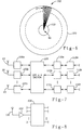
- FIG. 7 a representative portion of the second embodiment of the cellular communication system is illustrated.
- Three of the one hundred and twenty radiating elements 20 of the phased array antenna 18 are illustrated coupled to three digital beam forming networks 106a - 106c .
- the cellular communication system includes one hundred and twenty of the digital beam forming networks that are represented by networks 106a - 106c and are coupled to one of the radiating elements 20 .
- Each of the digital beam forming networks 106a - 106c includes a transmit section that transmits the user signals to the radiating elements and includes one of the transmitting digital beam forming networks 40a - 40d as illustrated in Fig.
- each of the digital beam forming networks 106a - 106c includes a receiving section that receives the user signals from the radiating elements and includes one of the receiving digital beam forming networks 60a -60d illustrated in Fig. 5 along with one of the combined pre-amplifier and analog to digital converter networks 56a - 56c .
- each of the amplitude and phase controls elements 42 and 62 are fixed such that the coverage areas of the personalized communication beams 102 are fixed as illustrated in FIG. 6 .
- a switching network 108 couples each of the digital beam forming networks 106a - 106c to modulating/demodulating networks 110a - 110c .
- the total number of modulating/demodulating networks as represented by networks 110a - 110c preferably corresponds to at least the number of users located within the cell 100 .
- Each of the modulating/demodulating networks 110a - 110c includes one of the modulators 38a - 38c and one of the demodulators 68a - 68d .
- the modulating/demodulating networks 110a - 110c employ a spread spectrum communication method including CDMA techniques such that each of the users within the cell 100 are assigned to a carrier frequency and a code assignment that is retained throughout the cell 100 .
- the switching network 108 is coupled to user tracking assemblies 112a - 112c through the modulating/demodulating networks 110a - 110c .
- the total number of the user tracking assemblies as represented by assemblies 112a - 112c corresponds to at least the number of users located within the cell 100 .
- Each of the user tracking assemblies 112a - 112c includes an amplitude comparator such as the amplitude comparator 72b illustrated in Fig. 5 for comparing the relative amplitudes of a user signal represented by the fixed communication beams 102 .
- the user tracking assemblies 112a - 112c perform the comparison to determine which of the fixed personalized communication beams provides the strongest signal coverage for each of the system users based upon each user's location in the cell 100 .
- the switching network 108 is provided with tracking signals for periodically switching the modulating/demodulating networks 110a - 110c between the beam forming networks 106a - 106c which, in turn, switches the users between the beams 102 .
- a particular user assigned to modulating/demodulating network 110b may initially be provided with signal coverage though the beam forming network 106b and the fixed communication beam associated therewith.
- the user tracking network 112b compares the relative amplitudes of the user signal as represented by the fixed communication beams adjacent to the user's initial communication beam and determines the signal power ratios.
- the switching network 108 switches or couples the modulating/demodulating network 110b to either of the adjacent beam forming networks 106a or 106c depending on the direction that the user is traveling.
- the omnidirectional antenna 120 is shown coupled to a preamplifier and analog to digital converter 122 which in turn is coupled to the switching network 108 .
- the omnidirectional antenna 120 may be positioned in closed proximity to the center location 90 for transmitting and receiving an omnidirectional communication beam to users within approximately one half of a mile of the center location 90 as illustrated by circle 103 .
- the switching network 108 switches the modulating/demodulating networks 110a - 110c between the phased array antenna 18 and the omnidirectional antenna 120 when the user tracking networks 112a - 112c determine that a particular user is located within area illustrated by the circle 103 .
- the use of the omnidirectional antenna and omnidirectional personal communication beam reduces the probability of drop calls for users that may be moving rapidly between the communication beams 102 .
Abstract
Description
- This invention relates generally to a cellular communication system, and more particularly, to a cellular communication system utilizing a phased array antenna in conjunction with a spread spectrum communications method which includes code division multiple access techniques for generating a plurality of highly directive adjustable or fixed personalized communication beams that provide signal coverage to system users throughout an original geographical cell.
- Today's cellular communication systems are constantly subjected to ever increasing user demands, particularly in urban areas. In order to accommodate for such higher user demands, the practice of "cell splitting" has become a common solution for cellular communication systems requiring additional user capacity. The practice of "cell splitting" involves the splitting of a cellular communication system's original geographical cells into smaller geographical cells commonly referred to as "microcells". A "microcell" is commonly defined as a geographical cell having a radius of approximately one thousand feet or less. The practice of "cell splitting" increases a cellular communication system's capacity by increasing the total number of cells, thereby increasing the ability to reuse frequencies between sufficiently isolated cells.
- Typically, each of a cellular communication system's original geographical cells employ a base station with an antenna that provides signal coverage throughout a given original cell. Such base stations commonly include an omnidirectional antenna that provides signal coverage throughout the entire original cell or a sectorized antenna that divides the cell into a number of signal coverage sectors. Unfortunately, as an original geographical cell is split into a number of smaller geographical cells, a corresponding number of additional base stations with antennas are required to provide signal coverage within the boundaries of the additional cells. As a result, each time the original geographical cell is split into smaller cells, the cost of the cellular communication system is increased due to the increased hardware costs.
- Another problem associated with the practice of "cell splitting" is the increase in the number of "handovers" required as users travel between the increased number of cells. This in turn increases the probability of drop calls within the geographical area previously covered by an original geographical cell. Additionally, the reduced effective radiation area of "microcells" may cause irregular user signal strengths and signal interference between adjacent "microcells".
- Fig. 1 illustrates a conventional cellular communication system's original
geographical cell 10 that has been split into numerous smallergeographical cells 12. Theoriginal cell 10 may have originally included asingle base station 14 located at a center location which is now illustrated as providing signal coverage for one of thesmaller cells 12. Each of thesmaller cells 12 includes anadditional base station 16 and an accompanying antenna for providing signal coverage for users located within each of thesmaller cells 12. As previously discussed, the addition of thesmaller cells 12 increases the costs of providing signal coverage for the users located in the geographical area previously associated with the originalgeographical cell 10. - As such, it would be desirable to produce a cellular communication system having increased user capacity without requiring "cell splitting" and the additional costs associated therewith. Furthermore, it would be desirable to provide a cellular communication system that utilizes a phased array antenna and user tracking assemblies for transmitting highly directive adjustable or fixed personalized communication beams representing user signals in the directions of each of the system users located within an original geographical cell.
- In accordance with the present invention, a cellular communication system is provided for transmitting highly directive personalized communication beams to system users located within an original geographical cell of the cellular communication system. Each of the personalized communication beams represents user signals assigned to specific users located within the original geographical cell.
- In accordance with the first embodiment, a phased array antenna is positioned within the original geographical cell for transmitting and receiving personalized communication beams that are adjustable in the directions of each of the users within the cell. A digital beam forming apparatus feeds the phased array antenna with user signals that form the adjustable personalized communication beams which are transmitted in the individual directions of the system users located within the geographical cell. The digital beam forming apparatus also receives the user signals received by the phased array antenna. A user tracking apparatus provides the digital beam forming apparatus with tracking information regarding the relative amplitudes of the user signals such that the digital beam forming apparatus adjusts each of the user signals to substantially center each of the adjustable personalized communication beams about one of the system users.
- In accordance with a preferred embodiment, an omnidirectional antenna is positioned in close proximity to a center location of the geographical cell for transmitting and receiving an omnidirectional communication beam in the directions of the system users traveling within a predetermined range of the center location.
- In accordance with a second embodiment, a phased array antenna is positioned within the geographical cell for transmitting and receiving a fixed number of personalized communication beams in fixed directions such that signal coverage is provided throughout the geographical cell. A plurality of digital beam forming networks feed the phased array antenna with user signals that form the fixed personalized communication beams. The plurality of digital beam forming networks also receive the user signals received by the phased array antenna. A plurality of modulating/demodulating networks corresponding to at least the number of the users within the geographical cell modulate and demodulate the user signals assigned to each of the particular users. A switching network switches the plurality of modulating/demodulating networks between the plurality of digital beam forming networks such that each of the system users is assigned to one of the fixed personalized communication beams providing maximum signal coverage with respect to each of the user's locations. A user tracking apparatus tracks each user and provides the switching network with tracking information regarding the amplitudes of the user signals represented by the communication beams. As a result, the aforementioned problems associated with cellular communication system utilizing "cell splitting" to increase user capacity should be substantially eliminated.
- The various advantages of the present invention will become apparent to those skilled in the art after reading the following specification and by reference to the drawings in which:
- FIG. 1 is a simplified illustration of a prior art cellular communication system utilizing "cell splitting" to increase user capacity;
- FIG. 2 is simplified illustration of the phased array antenna used in conjunction with the cellular communication system in accordance with the present invention;
- FIG. 3 illustrates the adjustable personalized communication beams transmitted by the phased array antenna to each of the system users located within an original geographical cell of the cellular communication system in accordance with a first embodiment of the present invention;
- FIG. 4 is a schematic illustration of a portion of the transmitting network of the cellular communication system coupled to the phased array antenna in accordance with the present invention;
- FIG. 5 is a schematic illustration of a portion of the receiving network of the cellular communication system coupled between the phased array antenna and the user tracking assemblies in accordance with the present invention;
- FIG. 6 illustrates the fixed personalized communication beams transmitted by a phased array antenna for providing signal coverage throughout an original geographical cell of the cellular communication system in accordance with a second embodiment of the present invention;
- FIG. 7 is a block diagram of the cellular communication system in accordance with the second embodiment of the present invention; and
- FIG. 8 is a schematic illustration of an omnidirectional antenna for providing signal coverage to users within a predetermined range of the base stations of the cellular communication system in accordance with the first and second embodiments of present invention.
- The following description of the preferred embodiments is merely exemplary in nature and is in no way intended to limit the invention or its application or uses.
- FIG. 2 illustrates a
phased array antenna 18 that may be used in conjunction with the cellular communication system of the present invention. Thephased array antenna 18 includes a plurality ofradiating elements 20 which are positioned about acircle 22 having a radius(r) of approximately ten feet. This configuration includes one hundred and twenty of theradiating elements 20 each of which are separated by a distance(d) of approximately six inches. It should be noted that phased array antennas having a different number of radiating elements and different physical configurations may be used in conjunction with the cellular communication system of the present invention. - In accordance with the present invention, the
phased array antenna 18 is configured for transmitting a large number of highly directive adjustable or fixed electromagnetic beams of radiation for communication purposes. Each of the communication beams has a beam width of approximately three degrees allowing each of the beams to be substantially centered about an individual user of the system. The high directivity of the communication beams allows each of the beams to be personalized for each user within a cell of the system. In addition, the communication beams are personalized through the use of well known cellular signaling methods such as a spread spectrum communication method which includes code division multiple access (CDMA) techniques wherein a particular user is assigned to a spread spectrum code and a carrier frequency which are retained throughout a cell of the system. The operation of phased array antennas is well known in the art and will not be discussed in detail herein. - In accordance with the first embodiment of the present invention, Fig. 3 illustrates the
phased array antenna 18 mounted to an existing base station located at acenter location 24 of an originalgeographical cell 26 of the cellular communication system. Thephased array antenna 18 transmits adjustable personalizedcommunication beams 28 representing user signals in the individual directions of each of the users located within thecell 26. For purposes of simplification, only five of thebeams 28 are illustrated, but the number of beams may reach the many thousands. In order to improve signal reception, an omnidirectional antenna, as illustrated in Fig. 8, may be positioned in close proximity to thecenter location 24 for transmitting an omnidirectional communication beam to users traveling within approximately one half of a mile of thecenter location 24 as illustrated by acircle 30. The use of the omnidirectional communication beam reduces or eliminates the problem of dropped calls for users which are moving rapidly throughout the area illustrated by thecircle 30. - The
phased array antenna 18 may also be applied in a "green field" area, i.e. a geographical area which is not presently serviced by a cellular communication system, thereby extending the range and area covered by a newly created cell in such an area while requiring fewer base stations. - FIGS. 4 and 5 respectively illustrate representative portions of a transmitting
network 34 and a receivingnetwork 36 of the cellular communication system. Both the transmittingnetwork 34 and the receivingnetwork 36 are coupled to the radiatingelements 20 of the phasedarray antenna 18. As previously discussed, the phasedarray antenna 18 is located at thecenter location 24 of thecell 26 of the cellular communication system. For purposes of simplification, only four of the one hundred and twenty radiatingelements 20 are illustrated in FIG. 4, and three of the radiatingelements 20 are illustrated in FIG. 5. The phasedarray antenna 18 is used in conjunction with the transmittingnetwork 34 to transmit and adjust the direction of thepersonalized communication beams 28 representing user signals in the individual directions of each of the users within thecell 26. - Referring to FIG. 4, the representative portion of the transmitting
network 34 is illustrated includingsignal modulators 38a - 38c that modulate three user signals that may be received a telephone network (not shown). By way of example, the transmittingnetwork 34 may receive user signals from another base station in the cellular communication system via land based communication lines or additional receivers located within the base station. Such sources of user signals represent other subscribers within the cellular communication system communicating to a particular user. The total number of signal modulators for the transmittingnetwork 34 corresponds to at least the number of system users located within thecell 26. As such, each user is assigned to a unique user signal and one of thepersonalized communication beams 28 that is retained throughout theentire cell 26. - As previously indicated, the
signal modulators 38a - 38c advantageously utilize a spread spectrum communication method which includes code division multiple access (CDMA) techniques to increase the number of users that can be accommodated within the allocated frequency spectrum ofcell 26 and the cellular communication system. Each of the users within thecell 26 is assigned to a carrier frequency and a code assignment which are retained throughout the cell. Therefore, the problems typically associated with cellular communications systems utilizing "microcells" including, but not limited to, increased "handovers", irregular user signal strengths and interference are substantially eliminated. Additionally, the implementation of CDMA techniques in conjunction with the highly efficient personalized communication beams reduces the transmit power requirements which increases the battery life of user handsets. - The transmitting
network 34 is illustrated further including transmitting digitalbeam forming networks 40a - 40d that each include variable amplitude andphase control elements 42 for synthesizing a desired antenna beam shape from the modulated user signals received from each of thesignal modulators 38a - 38c. The total number of transmitting digital beam forming networks represented bynetworks 40a - 40d corresponds to the number of radiatingelements 20 in the phasedarray antenna 18. Each of the transmitting digitalbeam forming networks 40a - 40d is illustrated including three variable amplitude andphase control elements 42, each corresponding to one of thesignal modulators 38a - 38c. However, the total of number of variable amplitude andphase control elements 42 in each of the transmitting digital beam forming networks corresponds to the total number signal modulators and, in turn, at least the number of users within thecell 26. Each of the variable amplitude andphase control elements 42 are adjusted to change the relative amplitudes and phases of the modulated user signals such that the personalized communication beams are substantially centered about the individual system users. -
Combiners 44a - 44d combine the signals received from the amplitude andphase control elements 42 and output synthesized user signals. Each of the synthesized user signals are fed to digital toanalog converters 46a - 46d, band pass filters 48a - 48d, andpower amplifiers 50a - 50d. The radiatingelements 20 transmit the adjustablepersonalized communication beams 28, representing the modulated signals from thesignal modulators 38a - 38c, in the individual directions of specific users within thecell 26. - Each of the transmitting digital
beam forming networks 40a - 40d receive tracking information regarding each of the system users aboutinput lines 52a - 52d. This information is used to adjust the amplitude andphase control elements 42 such that the shapes and directions of thepersonalized communication beams 28 transmitted from each of the radiatingelements 20 are adjusted as the system users move throughout thecell 26. - Turning to FIG. 5, the representative portion of the receiving
network 36 is illustrated including four receivingbeam forming networks 60a - 60d that receive the user signals from the radiatingelements 20 of the phasedarray antenna 18. The user signals are amplified and converted to digital signals by the combined preamplifier and analog todigital converter networks 56a - 56c. The total number of receiving beam forming networks represented bynetworks 60a - 60d corresponds to at least the number of system users located within thecell 26. Each of the receiving digitalbeam forming networks 60a - 60d is illustrated including three variable amplitude andphase control elements 62 corresponding to the radiatingelements 20 for synthesizing desired antenna beam shapes from the received user signals. The total number of the variable amplitude andphase control elements 62 for each of the receivingbeam forming networks 60a - 60c corresponds to the total number of the radiatingelements 20 in thephase array antenna 18. -
Combiners 64a - 64d combine the signals received from the variable amplitude andphase control elements 62 such that each of the receiving digitalbeam forming networks 60a - 60d outputs a synthesized user signal.Switching networks 66a - 66d feed the synthesized user signals todemodulators 68a - 68d. As with the receivingbeam forming networks 60a - 60d, the total number of demodulators corresponds to at least the number of users within thecell 26 of the cellular communication system. Therefore, each of thedemodulators 68a - 68d demodulates a synthesized user signal from a corresponding beam forming network and outputs a desired user signal assigned to a particularly user within thecellular cell 26. As with themodulators 38a - 38c of the transmittingnetwork 34, thedemodulators 68a - 68d employ a spread spectrum communication method including CDMA techniques. - The receiving
network 36 is coupled to user tracking assemblies that track each of the users located within thecell 26 according to user signal power ratios with respect to adjacent communication beams 28. The user tracking assemblies provide the receiving and transmittingbeam forming networks 60a - 60d and 40a - 40d with tracking signals for adjusting the transmitting directions of the communication beams 28 in the directions of each of the system users. Each of the transmittingbeam forming networks 60a - 60d and thedemodulators 68a - 68d are coupled to user tracking assemblies as represented byuser tracking assembly 70b. The operation of the user tracking assemblies of the system will be described with reference to theuser tracking assembly 70b. - The representative
user tracking assembly 70b is illustrated coupled tobeam forming network 60b and thedemodulator 68b. Theuser tracking assembly 70b includes anamplitude comparator 72b andmicroprocessors demodulator 68b and the corresponding adjustable personalized communication beam, the relative amplitudes of the user signal as represented by the adjacent communication beams ofbeam forming networks beam forming network 60b. Theswitching network 66b samples the synthesized user signals outputted by the receiving digitalbeam forming networks 60a - 60c and serially feeds the respective signals to thedemodulator 68b. Thedemodulator 68b demodulates the particular user signal from the sampled synthesized signals and theamplitude comparator 72b compares the relative amplitudes of the particular user signals. Thecomparator 72b also outputs the desired user signal to the telephone network (not shown) aboutline 74b. Themicroprocessors beam forming network 60b and the transmitting digitalbeam forming network 40b using lines lines - The tracking signals are used to adjust the amplitude and phase controls 42 and 62 of the transmitting and receiving digital
beam forming networks 40a - 40d and 60a - 60d such that each of the individual personalized communication beams 28 is substantially centered about a particular user within thecell 26. This type of beam tracking also allows for the implementation of user services such as, but not limited to, traffic management, driving directions, and vehicle theft locating. - In accordance with the second embodiment of the present invention, the cellular communication system transmits a fixed number of personalized communication beams in fixed directions such that signal coverage is provided throughout an original geographical cell of the system. As illustrated in FIG. 6, the phased
array antenna 18 is located substantially at acenter location 90 of an originalgeographical cell 100 of the cellular communication system. The phasedarray antenna 18 preferably transmits two hundred forty personal communication beams 102, each having a beam width of approximately three degrees. Each of the communication beams 102 overlaps adjacent beams by approximately one and a half degrees. This beam pattern provides thecell 100 with overlapped signal coverage throughout the full three hundred and sixty degree spectrum. As in with first embodiment, each of thepersonalized communication beams 102 represents user signals assigned to specific users within thecell 100. - As the users travel throughout the
cell 100, each are tracked and reassigned todifferent communication beams 102 that provide the highest signal power ratio based on a user's location. With reference to FIGS. 6 and 8, anomnidirectional antenna 120 may be positioned in closed proximity to thecenter location 90 for transmitting and receiving an omnidirectional communication beam to users traveling within approximately one half of a mile of thecenter location 90 as illustrated bycircle 103. As with the omnidirectional antenna of the first embodiment, the use of the omnidirectional communication beam improves signal reception and reduces the probability of dropped calls for the users traveling in the close proximity of thecenter location 90. - Turning to FIG. 7, a representative portion of the second embodiment of the cellular communication system is illustrated. Three of the one hundred and twenty radiating
elements 20 of the phasedarray antenna 18 are illustrated coupled to three digitalbeam forming networks 106a - 106c. The cellular communication system includes one hundred and twenty of the digital beam forming networks that are represented bynetworks 106a - 106c and are coupled to one of the radiatingelements 20. Each of the digitalbeam forming networks 106a - 106c includes a transmit section that transmits the user signals to the radiating elements and includes one of the transmitting digitalbeam forming networks 40a - 40d as illustrated in Fig. 4 along with one of the corresponding digital toanalog converters 46a - 46d, one of thebandpass filters 48a - 48d, and one of thepower amplifiers 50a - 50d. In addition, each of the digitalbeam forming networks 106a - 106c includes a receiving section that receives the user signals from the radiating elements and includes one of the receiving digitalbeam forming networks 60a -60d illustrated in Fig. 5 along with one of the combined pre-amplifier and analog todigital converter networks 56a - 56c. In accordance with the second embodiment, each of the amplitude andphase controls elements personalized communication beams 102 are fixed as illustrated in FIG. 6. - A
switching network 108 couples each of the digitalbeam forming networks 106a - 106c to modulating/demodulating networks 110a - 110c. The total number of modulating/demodulating networks as represented bynetworks 110a - 110c preferably corresponds to at least the number of users located within thecell 100. Each of the modulating/demodulating networks 110a - 110c includes one of themodulators 38a - 38c and one of thedemodulators 68a - 68d. As with the first embodiment of the present invention, the modulating/demodulating networks 110a - 110c employ a spread spectrum communication method including CDMA techniques such that each of the users within thecell 100 are assigned to a carrier frequency and a code assignment that is retained throughout thecell 100. - The
switching network 108 is coupled touser tracking assemblies 112a - 112c through the modulating/demodulating networks 110a - 110c. The total number of the user tracking assemblies as represented byassemblies 112a - 112c corresponds to at least the number of users located within thecell 100. Each of theuser tracking assemblies 112a - 112c includes an amplitude comparator such as theamplitude comparator 72b illustrated in Fig. 5 for comparing the relative amplitudes of a user signal represented by the fixed communication beams 102. Theuser tracking assemblies 112a - 112c perform the comparison to determine which of the fixed personalized communication beams provides the strongest signal coverage for each of the system users based upon each user's location in thecell 100. - In contrast to the first embodiment wherein the comparison is made to adjust the directions of communication beams 28, the
switching network 108 is provided with tracking signals for periodically switching the modulating/demodulating networks 110a - 110c between thebeam forming networks 106a - 106c which, in turn, switches the users between thebeams 102. For example, a particular user assigned to modulating/demodulating network 110b may initially be provided with signal coverage though thebeam forming network 106b and the fixed communication beam associated therewith. As the user travels throughout thecell 100, theuser tracking network 112b compares the relative amplitudes of the user signal as represented by the fixed communication beams adjacent to the user's initial communication beam and determines the signal power ratios. Once it is determined that the particular user would be provided with stronger signal coverage through an adjacent communication beam, theswitching network 108 switches or couples the modulating/demodulating network 110b to either of the adjacentbeam forming networks - Turning to FIG. 8, the
omnidirectional antenna 120 is shown coupled to a preamplifier and analog todigital converter 122 which in turn is coupled to theswitching network 108. As previously mentioned, theomnidirectional antenna 120 may be positioned in closed proximity to thecenter location 90 for transmitting and receiving an omnidirectional communication beam to users within approximately one half of a mile of thecenter location 90 as illustrated bycircle 103. Theswitching network 108 switches the modulating/demodulating networks 110a - 110c between the phasedarray antenna 18 and theomnidirectional antenna 120 when theuser tracking networks 112a - 112c determine that a particular user is located within area illustrated by thecircle 103. The use of the omnidirectional antenna and omnidirectional personal communication beam reduces the probability of drop calls for users that may be moving rapidly between the communication beams 102. - The foregoing discloses and describes merely exemplary embodiments of the present invention. One skilled in the art will readily recognize from such discussion, and from the accompanying drawings and claims, that various changes, modifications, and variations can be made therein without departing from the spirit and scope of the present invention as defined by the following claims.
Claims (19)
- A cellular communication system for transmitting adjustable personalized communication beams in individual directions of a plurality of users located within a geographical cell of the cellular communication system, each of the adjustable personalized communication beams representing user signals assigned to specific users within the geographical cell, comprising:phased array antenna means, positioned within the geographical cell, for transmitting and receiving the adjustable personalized communication beams;digital beam forming means for feeding the phased array antenna means with the user signals forming the adjustable personalized communication beams for transmission in the individual directions of the plurality of users and for receiving the user signals received by the phased array antenna means; anduser tracking means for providing the digital beam forming means with user tracking information such that the digital beam forming means adjusts each of the user signals so that each of the adjustable personalized communication beams is substantially centered about one of the users.
- The cellular communication system of Claim 1, wherein the phased array antenna means is located substantially at a center location of the geographical cell.
- The cellular communication system of Claim 1, further comprising:omnidirectional antenna means, positioned in close proximity to a center location of the geographical cell, for transmitting and receiving an omnidirectional communication beam in directions of users within a predetermined range of the center location.
- The cellular communication system of Claim 1, wherein the digital beam forming means includes:a transmitting network for transmitting the user signals represented by the adjustable personalized communication beams in directions of the plurality of users including:(a) a plurality of signal modulators corresponding to at least the number of the users for modulating the user signals assigned to each of the users, and(b) a plurality of transmitting digital beam forming networks for feeding the modulated user signals to the phased array antenna means such that each of the adjustable personalized communication beams is transmitted in a direction of a particular user; anda receiving network for receiving the user signals received by the phased array antenna means including:(a) a plurality of receiving digital beam forming networks for synthesizing the user signals, and(b) a plurality of signal demodulators corresponding to at least the number of the users each coupled to outputs of the receiving digital beam forming networks for demodulating the user signals assigned to each of the users.
- The cellular communication system of Claim 1, wherein the user tracking means includes a plurality of amplitude comparator networks each for comparing relative amplitudes of a particular user signal represented by a first adjustable personalized communication beam and at least two other adjustable personalized communication beams adjacent to the first adjustable personalized communication beam.
- The cellular communication system of Claim 4, wherein the user tracking means includes:a plurality of amplitude comparator networks, coupled to outputs of the demodulators, each for comparing relative amplitudes of a particular user signal represented by a first adjustable personalized communication beam and at least two other adjustable personalized communication beams adjacent to the first adjustable personalized communication beam; andswitching means for providing the user signals represented by the first adjustable personalized communication beam and the at least two other adjacent adjustable personalized communication beams to a demodulator assigned to the first adjustable personalized communication beam.
- The cellular communication system of Claim 4, wherein the signal modulators modulate the user signals using code division multiple access coded spread spectrum signals.
- The cellular communication system of Claim 4, wherein the phased array antenna means includes a plurality of radiating elements for transmitting and receiving the adjustable personalized communication beams.
- The cellular communication system of Claim 8, wherein each of the receiving digital beam forming networks includes variable amplitude and phase control elements corresponding to the number of radiating elements, and wherein each of the transmitting digital beam forming networks includes variable amplitude and phase control elements corresponding to at least the number of the users.
- A cellular communication system for transmitting a fixed number of personalized communication beams in fixed directions covering a geographical cell of the cellular communication system, each of the personalized communication beams representing user signals assigned to specific users within the geographical cell, comprising:phased array antenna means, positioned within the geographical cell, for transmitting and receiving the fixed personalized communication beams;a plurality of digital beam forming networks for feeding the phased array antenna means with the user signals forming the fixed personalized communication beams and for receiving the user signals represented by the fixed personalized communication beams;a plurality of modulating/demodulating networks corresponding to at least the number of the users for modulating and demodulating the user signals assigned to each of the users;switching means for switching the plurality of modulating/demodulating networks between the plurality of digital beam forming networks such that each of the users is assigned to a fixed personalized communication beam providing maximum signal coverage; anduser tracking means for tracking each of the users and for providing the switching means with user tracking information such that the switching means switches the plurality of modulating/demodulating networks between the plurality of digital beam forming networks.
- The cellular communication system of Claim 10, wherein the phased array antenna means is located substantially at a center location of the geographical cell.
- The cellular communication system of Claim 10, further comprising:omnidirectional antenna means, positioned in close proximity to the center location of the geographical cell, for transmitting and receiving an omnidirectional communication beam in directions of users within a predetermined range of the center location of the geographical cell.
- The cellular communication system of Claim 10, wherein the user tracking means includes a plurality of amplitude comparator networks each for comparing relative amplitudes of a particular user signal represented by a first fixed personalized communication beam and at least two other fixed personalized communication beams adjacent to the first fixed personalized communication beam.
- The cellular communication system of Claim 10, wherein the modulating/demodulating networks modulate the user signals using code division multiple access coded spread spectrum signals.
- The cellular communication system of Claim 10, wherein each of the digital beam forming networks include fixed amplitude and phase control elements.
- The cellular communication system of Claim 10, wherein the phased array antenna means includes a number of radiating elements corresponding the number of digital beam forming networks for transmitting and receiving the fixed personalized communication beams.
- The cellular communication system of Claim 10, wherein the phased array antenna means includes a plurality of radiating elements each transmitting the fixed personalized communication beams such that adjacent beams have overlapping signal coverage areas.
- The cellular communication system of Claim 17, wherein the radiating elements transmit substantially two hundred and forty of the fixed personalized communication beams, each the fixed personalized communication beams having a three degree signal coverage area and overlapping adjacent beams by approximately one and a half degrees.
- A phase array antenna for use in a cellular communication system positioned substantially at a center location of a geographical cell of the cellular communication system, comprising:a plurality of radiating elements for transmitting personalized communication beams, each of the radiating elements being positioned about a circumference of a circle having substantially a ten foot radius, each of the radiating elements being separated by a constant distance and receiving user signals from a plurality of digital beam forming networks for shaping the personalized communication beams such that signal coverage is provide throughout the geographical cell.
Applications Claiming Priority (2)
| Application Number | Priority Date | Filing Date | Title |
|---|---|---|---|
| US08/592,749 US5815116A (en) | 1995-11-29 | 1995-11-29 | Personal beam cellular communication system |
| US592749 | 1995-11-29 |
Publications (2)
| Publication Number | Publication Date |
|---|---|
| EP0777400A2 true EP0777400A2 (en) | 1997-06-04 |
| EP0777400A3 EP0777400A3 (en) | 1999-05-12 |
Family
ID=24371920
Family Applications (1)
| Application Number | Title | Priority Date | Filing Date |
|---|---|---|---|
| EP96113313A Withdrawn EP0777400A3 (en) | 1995-11-29 | 1996-08-20 | Personal beam cellular communication system |
Country Status (4)
| Country | Link |
|---|---|
| US (1) | US5815116A (en) |
| EP (1) | EP0777400A3 (en) |
| JP (1) | JPH09182148A (en) |
| KR (1) | KR100440652B1 (en) |
Cited By (28)
| Publication number | Priority date | Publication date | Assignee | Title |
|---|---|---|---|---|
| GB2318914A (en) * | 1996-10-30 | 1998-05-06 | Motorola Inc | Digital beam forming system for an antenna array |
| GB2318947A (en) * | 1996-10-30 | 1998-05-06 | Motorola Inc | Intelligent digital beam forming system responsive to traffic demand |
| WO1999022532A1 (en) * | 1997-10-27 | 1999-05-06 | Siemens Aktiengesellschaft | Method, base station, receiving device and mobile station for transmitting useful information and signalling information for a mobile communications system |
| WO1999026441A1 (en) * | 1997-11-13 | 1999-05-27 | Metawave Communications Corporation | Input specific independent sector mapping |
| WO1999034478A1 (en) * | 1997-12-31 | 1999-07-08 | Silicon Wireless Limited | Improved positioning of shaped directional transmitting and transmitting/receiving antenna array elements |
| WO1999040648A1 (en) * | 1998-02-09 | 1999-08-12 | Arraycomm, Inc. | Downlink broadcasting by sequential transmissions from a communication station having an antenna array |
| EP0942489A1 (en) * | 1998-02-17 | 1999-09-15 | ATR Adaptive Communications Research Laboratories | Array antenna apparatus for use in spread spectrum communications with a particular interval between antenna elements |
| GB2335572A (en) * | 1998-03-18 | 1999-09-22 | Fujitsu Ltd | Multiple beam antenna system |
| WO1999060659A1 (en) * | 1998-05-15 | 1999-11-25 | Raytheon Company | Adaptive antenna pattern control for a multiple access communication system |
| NL1009298C2 (en) * | 1998-06-02 | 1999-12-03 | Chung Shan Inst Of Science | 'Intelligent' antenna system based on a spatial filter bank, automatically traces the use conditions of subscriber stations in which a simple system works with high efficiency |
| EP0992813A2 (en) * | 1998-10-09 | 2000-04-12 | Matsushita Electric Industrial Co., Ltd. | Radio wave arrival direction estimating antenna apparatus |
| WO2000067508A1 (en) * | 1999-05-01 | 2000-11-09 | Nokia Corporation | A method of directional radio communication |
| US6178333B1 (en) | 1998-04-15 | 2001-01-23 | Metawave Communications Corporation | System and method providing delays for CDMA nulling |
| US6198435B1 (en) | 1997-01-27 | 2001-03-06 | Metawave Communications Corporation | System and method for improved trunking efficiency through sector overlap |
| US6246674B1 (en) | 1997-01-27 | 2001-06-12 | Metawave Communications Corporation | Antenna deployment sector cell shaping system and method |
| EP1184938A1 (en) * | 2000-08-09 | 2002-03-06 | Lucent Technologies Inc. | Dynamic load sharing system and method using a cylindrical antenna array |
| US6421005B1 (en) | 2000-08-09 | 2002-07-16 | Lucent Technologies Inc. | Adaptive antenna system and method |
| GB2384652A (en) * | 2002-01-29 | 2003-07-30 | Hutchison Whampoa Three G Ip | Communication using a multi-sectored directional antenna array |
| US6615024B1 (en) | 1998-05-01 | 2003-09-02 | Arraycomm, Inc. | Method and apparatus for determining signatures for calibrating a communication station having an antenna array |
| US6658269B1 (en) | 1999-10-01 | 2003-12-02 | Raytheon Company | Wireless communications system |
| US6690747B2 (en) | 1996-10-11 | 2004-02-10 | Arraycomm, Inc. | Method for reference signal generation in the presence of frequency offsets in a communications station with spatial processing |
| EP1392073A1 (en) * | 2002-08-23 | 2004-02-25 | NTT DoCoMo, Inc. | Base station, mobile communication system, and communication method for omnidirectional and directional transmission |
| US6795409B1 (en) | 2000-09-29 | 2004-09-21 | Arraycomm, Inc. | Cooperative polling in a wireless data communication system having smart antenna processing |
| GB2414900A (en) * | 2004-04-30 | 2005-12-07 | Nec Corp | Mobile communication system |
| US7751854B2 (en) | 1999-06-21 | 2010-07-06 | Intel Corporation | Null deepening for an adaptive antenna based communication station |
| USRE42224E1 (en) | 1999-05-24 | 2011-03-15 | Durham Logistics Llc | System and method for emergency call channel allocation |
| WO2012128809A1 (en) * | 2011-01-05 | 2012-09-27 | Alcatel-Lucent | Conformal antenna array |
| WO2018091203A1 (en) * | 2016-11-18 | 2018-05-24 | Sony Corporation | Communications apparatus, method and mobile communications system |
Families Citing this family (34)
| Publication number | Priority date | Publication date | Assignee | Title |
|---|---|---|---|---|
| JP3204111B2 (en) * | 1996-08-28 | 2001-09-04 | 松下電器産業株式会社 | Directivity control antenna device |
| US6463295B1 (en) | 1996-10-11 | 2002-10-08 | Arraycomm, Inc. | Power control with signal quality estimation for smart antenna communication systems |
| US7035661B1 (en) | 1996-10-11 | 2006-04-25 | Arraycomm, Llc. | Power control with signal quality estimation for smart antenna communication systems |
| JP3816162B2 (en) * | 1996-10-18 | 2006-08-30 | 株式会社東芝 | Beamwidth control method for adaptive antenna |
| GB2320618A (en) * | 1996-12-20 | 1998-06-24 | Northern Telecom Ltd | Base station antenna arrangement with narrow overlapping beams |
| ES2271966T3 (en) * | 1997-02-13 | 2007-04-16 | Nokia Corporation | METHOD AND APPARATUS FOR DIRECTIONAL RADIO COMMUNICATION. |
| JP2000509950A (en) | 1997-03-03 | 2000-08-02 | セレトラ・リミテッド | Method and system for improving communication |
| US6900775B2 (en) | 1997-03-03 | 2005-05-31 | Celletra Ltd. | Active antenna array configuration and control for cellular communication systems |
| JPH10336087A (en) * | 1997-05-30 | 1998-12-18 | Kyocera Corp | Maximum ratio synthesis transmission diversity device |
| JPH11298400A (en) * | 1998-04-10 | 1999-10-29 | Nec Saitama Ltd | Directional control circuit for adaptive antenna and directional controlling method |
| JP2001069070A (en) * | 1999-06-21 | 2001-03-16 | Kdd Corp | Mobile communication system having zone shift controller |
| US6782277B1 (en) * | 1999-09-30 | 2004-08-24 | Qualcomm Incorporated | Wireless communication system with base station beam sweeping |
| US6728554B1 (en) * | 2000-09-11 | 2004-04-27 | International Systems, Llc | Wireless communication network |
| US7295509B2 (en) | 2000-09-13 | 2007-11-13 | Qualcomm, Incorporated | Signaling method in an OFDM multiple access system |
| JP3558053B2 (en) * | 2001-06-06 | 2004-08-25 | 日本電気株式会社 | Adaptive antenna receiver |
| US20030017853A1 (en) * | 2001-07-12 | 2003-01-23 | Sarnoff Corporation | Method and apparatus for enhancing the data transmission capacity of a wireless communication system |
| WO2003007494A1 (en) * | 2001-07-13 | 2003-01-23 | Sarnoff Corporation | Method and apparatus for enhancing the data transmission capacity of a wireless communication system |
| US7327800B2 (en) * | 2002-05-24 | 2008-02-05 | Vecima Networks Inc. | System and method for data detection in wireless communication systems |
| US7146170B2 (en) * | 2002-12-10 | 2006-12-05 | Andrew Corp. | Wireless network management system |
| US7327795B2 (en) * | 2003-03-31 | 2008-02-05 | Vecima Networks Inc. | System and method for wireless communication systems |
| US20050073970A1 (en) * | 2003-10-01 | 2005-04-07 | Davidson Darren J. | Wireless communications network management system |
| US8385937B2 (en) * | 2004-07-07 | 2013-02-26 | Toshiba America Research Inc. | Load equalizing antennas |
| US9137822B2 (en) | 2004-07-21 | 2015-09-15 | Qualcomm Incorporated | Efficient signaling over access channel |
| JP4086833B2 (en) * | 2004-10-27 | 2008-05-14 | 日本電波工業株式会社 | High frequency radio control method and high frequency radio system |
| US9246560B2 (en) * | 2005-03-10 | 2016-01-26 | Qualcomm Incorporated | Systems and methods for beamforming and rate control in a multi-input multi-output communication systems |
| US8625547B1 (en) * | 2005-03-11 | 2014-01-07 | At&T Intellectual Property Ii, L.P. | Two-tier wireless broadband access network |
| US9461859B2 (en) | 2005-03-17 | 2016-10-04 | Qualcomm Incorporated | Pilot signal transmission for an orthogonal frequency division wireless communication system |
| US9143305B2 (en) | 2005-03-17 | 2015-09-22 | Qualcomm Incorporated | Pilot signal transmission for an orthogonal frequency division wireless communication system |
| US8879511B2 (en) | 2005-10-27 | 2014-11-04 | Qualcomm Incorporated | Assignment acknowledgement for a wireless communication system |
| US8565194B2 (en) | 2005-10-27 | 2013-10-22 | Qualcomm Incorporated | Puncturing signaling channel for a wireless communication system |
| US8885628B2 (en) | 2005-08-08 | 2014-11-11 | Qualcomm Incorporated | Code division multiplexing in a single-carrier frequency division multiple access system |
| US20070041457A1 (en) | 2005-08-22 | 2007-02-22 | Tamer Kadous | Method and apparatus for providing antenna diversity in a wireless communication system |
| US8693405B2 (en) | 2005-10-27 | 2014-04-08 | Qualcomm Incorporated | SDMA resource management |
| US8045512B2 (en) | 2005-10-27 | 2011-10-25 | Qualcomm Incorporated | Scalable frequency band operation in wireless communication systems |
Citations (3)
| Publication number | Priority date | Publication date | Assignee | Title |
|---|---|---|---|---|
| US4730310A (en) * | 1985-05-03 | 1988-03-08 | American Telephone And Telegraph Company | Terrestrial communications system |
| EP0540387A2 (en) * | 1991-10-17 | 1993-05-05 | Alcatel N.V. | Cellular radio communication system with phased array antenne |
| EP0647978A2 (en) * | 1993-08-12 | 1995-04-12 | Nortel Networks Corporation | Base station antenna arrangement |
Family Cites Families (22)
| Publication number | Priority date | Publication date | Assignee | Title |
|---|---|---|---|---|
| US5191342A (en) * | 1981-08-06 | 1993-03-02 | The United States Of America As Represented By The Secretary Of The Navy | Fix-tracking system |
| US4949092A (en) * | 1984-11-08 | 1990-08-14 | Highes Aircraft Company | Modularized contoured beam direct radiating antenna |
| US4901307A (en) * | 1986-10-17 | 1990-02-13 | Qualcomm, Inc. | Spread spectrum multiple access communication system using satellite or terrestrial repeaters |
| US5193109A (en) * | 1989-02-06 | 1993-03-09 | Pactel Corporation | Zoned microcell with sector scanning for cellular telephone system |
| EP0461192B1 (en) * | 1989-03-03 | 1995-06-07 | Telia Ab | Method for planning radio cells |
| EP0435283B1 (en) * | 1989-12-28 | 1995-12-20 | Nec Corporation | Antenna arrangement system capable of reducing co-channel interference |
| US5175878A (en) * | 1990-02-02 | 1992-12-29 | At&T Bell Laboratories | Radio network with switching arrangement for coupling radios to a selected antenna out of a plurality of antennas |
| US5073900A (en) * | 1990-03-19 | 1991-12-17 | Mallinckrodt Albert J | Integrated cellular communications system |
| FR2674997B1 (en) * | 1991-04-05 | 1994-10-07 | Alcatel Espace | USEFUL LOAD ARCHITECTURE IN THE SPACE AREA. |
| US5303240A (en) * | 1991-07-08 | 1994-04-12 | Motorola, Inc. | Telecommunications system using directional antennas |
| US5515378A (en) * | 1991-12-12 | 1996-05-07 | Arraycomm, Inc. | Spatial division multiple access wireless communication systems |
| US5307075A (en) * | 1991-12-12 | 1994-04-26 | Allen Telecom Group, Inc. | Directional microstrip antenna with stacked planar elements |
| US5309166A (en) * | 1991-12-13 | 1994-05-03 | United Technologies Corporation | Ferroelectric-scanned phased array antenna |
| US5345599A (en) * | 1992-02-21 | 1994-09-06 | The Board Of Trustees Of The Leland Stanford Junior University | Increasing capacity in wireless broadcast systems using distributed transmission/directional reception (DTDR) |
| US5345499A (en) * | 1992-03-23 | 1994-09-06 | At&T Bell Laboratories | Method for increasing two tier macrocell/microcell subscriber capacity in a cellular system |
| US5333000A (en) * | 1992-04-03 | 1994-07-26 | The United States Of America As Represented By The United States Department Of Energy | Coherent optical monolithic phased-array antenna steering system |
| US5295180A (en) * | 1992-04-08 | 1994-03-15 | U S West Newvector Group, Inc. | Cellular telephone zone system |
| US5262789A (en) * | 1992-04-30 | 1993-11-16 | General Electric Company | Source identification system for closely separated spatial sources |
| US5247310A (en) * | 1992-06-24 | 1993-09-21 | The United States Of America As Represented By The Secretary Of The Navy | Layered parallel interface for an active antenna array |
| FR2695775B1 (en) * | 1992-09-11 | 1994-11-10 | France Telecom | Method for reconfiguring antenna beam coverage in a satellite network. |
| US5353332A (en) * | 1992-09-16 | 1994-10-04 | Ericsson Ge Mobile Communications Inc. | Method and apparatus for communication control in a radiotelephone system |
| US5422647A (en) * | 1993-05-07 | 1995-06-06 | Space Systems/Loral, Inc. | Mobile communication satellite payload |
-
1995
- 1995-11-29 US US08/592,749 patent/US5815116A/en not_active Expired - Lifetime
-
1996
- 1996-08-20 EP EP96113313A patent/EP0777400A3/en not_active Withdrawn
- 1996-11-14 JP JP8303296A patent/JPH09182148A/en active Pending
- 1996-11-22 KR KR1019960056620A patent/KR100440652B1/en not_active IP Right Cessation
Patent Citations (3)
| Publication number | Priority date | Publication date | Assignee | Title |
|---|---|---|---|---|
| US4730310A (en) * | 1985-05-03 | 1988-03-08 | American Telephone And Telegraph Company | Terrestrial communications system |
| EP0540387A2 (en) * | 1991-10-17 | 1993-05-05 | Alcatel N.V. | Cellular radio communication system with phased array antenne |
| EP0647978A2 (en) * | 1993-08-12 | 1995-04-12 | Nortel Networks Corporation | Base station antenna arrangement |
Non-Patent Citations (1)
| Title |
|---|
| SWALES S C ET AL: "A SPECTRUM EFFICIENT CELLULAR BASE-STATION ANTENNA ARCHITECTURE" MOBILE RADIO AND PERSONAL COMMUNICATIONS INTERNATIONAL CONFERENCE, 9-11 DEC. 1991, COVENTRY, GB, vol. 6, 1 January 1991, pages 272-279, XP002002263 * |
Cited By (55)
| Publication number | Priority date | Publication date | Assignee | Title |
|---|---|---|---|---|
| US6690747B2 (en) | 1996-10-11 | 2004-02-10 | Arraycomm, Inc. | Method for reference signal generation in the presence of frequency offsets in a communications station with spatial processing |
| GB2318914A (en) * | 1996-10-30 | 1998-05-06 | Motorola Inc | Digital beam forming system for an antenna array |
| GB2318947A (en) * | 1996-10-30 | 1998-05-06 | Motorola Inc | Intelligent digital beam forming system responsive to traffic demand |
| GB2318947B (en) * | 1996-10-30 | 2001-08-15 | Motorola Inc | Method and intelligent digital beam forming system responsive to traffic demand |
| GB2318914B (en) * | 1996-10-30 | 2001-05-09 | Motorola Inc | Method and intelligent digital beam forming system with improved signal quality communications |
| US6198435B1 (en) | 1997-01-27 | 2001-03-06 | Metawave Communications Corporation | System and method for improved trunking efficiency through sector overlap |
| US6246674B1 (en) | 1997-01-27 | 2001-06-12 | Metawave Communications Corporation | Antenna deployment sector cell shaping system and method |
| WO1999022532A1 (en) * | 1997-10-27 | 1999-05-06 | Siemens Aktiengesellschaft | Method, base station, receiving device and mobile station for transmitting useful information and signalling information for a mobile communications system |
| WO1999026441A1 (en) * | 1997-11-13 | 1999-05-27 | Metawave Communications Corporation | Input specific independent sector mapping |
| US6070090A (en) * | 1997-11-13 | 2000-05-30 | Metawave Communications Corporation | Input specific independent sector mapping |
| US6185440B1 (en) | 1997-12-10 | 2001-02-06 | Arraycomm, Inc. | Method for sequentially transmitting a downlink signal from a communication station that has an antenna array to achieve an omnidirectional radiation |
| WO1999034478A1 (en) * | 1997-12-31 | 1999-07-08 | Silicon Wireless Limited | Improved positioning of shaped directional transmitting and transmitting/receiving antenna array elements |
| EP2325944A1 (en) * | 1998-02-09 | 2011-05-25 | Intel Corporation | Downlink broadcasting by sequential transmissions from a communication station having an antenna array |
| CN100401829C (en) * | 1998-02-09 | 2008-07-09 | 埃瑞康姆有限责任公司 | Downlink broadcasting by sequential transmissions from a communication station having an antenna array |
| WO1999040648A1 (en) * | 1998-02-09 | 1999-08-12 | Arraycomm, Inc. | Downlink broadcasting by sequential transmissions from a communication station having an antenna array |
| EP0942489A1 (en) * | 1998-02-17 | 1999-09-15 | ATR Adaptive Communications Research Laboratories | Array antenna apparatus for use in spread spectrum communications with a particular interval between antenna elements |
| US6232927B1 (en) | 1998-02-17 | 2001-05-15 | Atr Adaptive Communications Research Laboratories | Array antenna apparatus for use in spread spectrum communications with a particular interval between antenna elements |
| US6347220B1 (en) | 1998-03-18 | 2002-02-12 | Fujitsu Limited | Multiple-beam antenna system of wireless base station |
| GB2335572B (en) * | 1998-03-18 | 2002-02-20 | Fujitsu Ltd | Multiple-beam antenna system of wireless base station |
| GB2335572A (en) * | 1998-03-18 | 1999-09-22 | Fujitsu Ltd | Multiple beam antenna system |
| US6178333B1 (en) | 1998-04-15 | 2001-01-23 | Metawave Communications Corporation | System and method providing delays for CDMA nulling |
| US6668161B2 (en) | 1998-05-01 | 2003-12-23 | Arraycomm, Inc. | Determining a spatial signature using a robust calibration signal |
| US6654590B2 (en) | 1998-05-01 | 2003-11-25 | Arraycomm, Inc. | Determining a calibration function using at least one remote terminal |
| US6615024B1 (en) | 1998-05-01 | 2003-09-02 | Arraycomm, Inc. | Method and apparatus for determining signatures for calibrating a communication station having an antenna array |
| US6236866B1 (en) | 1998-05-15 | 2001-05-22 | Raytheon Company | Adaptive antenna pattern control for a multiple access communication system |
| WO1999060659A1 (en) * | 1998-05-15 | 1999-11-25 | Raytheon Company | Adaptive antenna pattern control for a multiple access communication system |
| NL1009298C2 (en) * | 1998-06-02 | 1999-12-03 | Chung Shan Inst Of Science | 'Intelligent' antenna system based on a spatial filter bank, automatically traces the use conditions of subscriber stations in which a simple system works with high efficiency |
| US6529745B1 (en) | 1998-10-09 | 2003-03-04 | Matsushita Electric Industrial Co., Ltd. | Radio wave arrival direction estimating antenna apparatus |
| EP0992813A3 (en) * | 1998-10-09 | 2001-10-17 | Matsushita Electric Industrial Co., Ltd. | Radio wave arrival direction estimating antenna apparatus |
| EP0992813A2 (en) * | 1998-10-09 | 2000-04-12 | Matsushita Electric Industrial Co., Ltd. | Radio wave arrival direction estimating antenna apparatus |
| WO2000067508A1 (en) * | 1999-05-01 | 2000-11-09 | Nokia Corporation | A method of directional radio communication |
| US7072692B1 (en) | 1999-05-01 | 2006-07-04 | Nokia Corporation | Method of directional radio communication |
| US6763237B1 (en) | 1999-05-01 | 2004-07-13 | Nokia Networks Oy | Method and apparatus for the selection of radio transmission resources |
| US6771989B1 (en) | 1999-05-01 | 2004-08-03 | Nokia Networks Oy | Method of directional radio communication |
| USRE42224E1 (en) | 1999-05-24 | 2011-03-15 | Durham Logistics Llc | System and method for emergency call channel allocation |
| US7751854B2 (en) | 1999-06-21 | 2010-07-06 | Intel Corporation | Null deepening for an adaptive antenna based communication station |
| US6658269B1 (en) | 1999-10-01 | 2003-12-02 | Raytheon Company | Wireless communications system |
| US6400335B1 (en) | 2000-08-09 | 2002-06-04 | Lucent Technologies Inc. | Dynamic load sharing system and method using a cylindrical antenna array |
| US6421005B1 (en) | 2000-08-09 | 2002-07-16 | Lucent Technologies Inc. | Adaptive antenna system and method |
| EP1184938A1 (en) * | 2000-08-09 | 2002-03-06 | Lucent Technologies Inc. | Dynamic load sharing system and method using a cylindrical antenna array |
| US6795409B1 (en) | 2000-09-29 | 2004-09-21 | Arraycomm, Inc. | Cooperative polling in a wireless data communication system having smart antenna processing |
| GB2384652B (en) * | 2002-01-29 | 2005-11-23 | Hutchison Whampoa Three G Ip | Improved communications with mobile terminals in restricted areas |
| AU2003200262B2 (en) * | 2002-01-29 | 2007-04-26 | Hutchison Whampoa Three G Ip (Bahamas) Limited | Improved radio signal repeater |
| US7327980B2 (en) | 2002-01-29 | 2008-02-05 | Hutchison Whampoa Three Gip (Bahamas) Limited | Radio signal repeater |
| GB2384652A (en) * | 2002-01-29 | 2003-07-30 | Hutchison Whampoa Three G Ip | Communication using a multi-sectored directional antenna array |
| US7099697B2 (en) | 2002-08-23 | 2006-08-29 | Ntt Docomo, Inc. | Base station, mobile communication system, and communication method |
| EP1392073A1 (en) * | 2002-08-23 | 2004-02-25 | NTT DoCoMo, Inc. | Base station, mobile communication system, and communication method for omnidirectional and directional transmission |
| GB2414900B (en) * | 2004-04-30 | 2006-11-29 | Nec Corp | Mobile communication system |
| GB2414900A (en) * | 2004-04-30 | 2005-12-07 | Nec Corp | Mobile communication system |
| WO2012128809A1 (en) * | 2011-01-05 | 2012-09-27 | Alcatel-Lucent | Conformal antenna array |
| US8594735B2 (en) | 2011-01-05 | 2013-11-26 | Alcatel Lucent | Conformal antenna array |
| CN103460508A (en) * | 2011-01-05 | 2013-12-18 | 阿尔卡特朗讯 | Conformal antenna array |
| WO2018091203A1 (en) * | 2016-11-18 | 2018-05-24 | Sony Corporation | Communications apparatus, method and mobile communications system |
| US10651907B2 (en) | 2016-11-18 | 2020-05-12 | Sony Corporation | Communications apparatus, method and mobile communications system |
| US11184066B2 (en) | 2016-11-18 | 2021-11-23 | Sony Corporation | Communications apparatus, method and mobile communications system |
Also Published As
| Publication number | Publication date |
|---|---|
| KR970031419A (en) | 1997-06-26 |
| EP0777400A3 (en) | 1999-05-12 |
| US5815116A (en) | 1998-09-29 |
| KR100440652B1 (en) | 2005-09-28 |
| JPH09182148A (en) | 1997-07-11 |
Similar Documents
| Publication | Publication Date | Title |
|---|---|---|
| US5815116A (en) | Personal beam cellular communication system | |
| US6397082B1 (en) | Beamed antenna system | |
| US5596333A (en) | Method and apparatus for conveying a communication signal between a communication unit and a base site | |
| US6304762B1 (en) | Point to multipoint communication system with subsectored upstream antennas | |
| US5649287A (en) | Orthogonalizing methods for antenna pattern nullfilling | |
| USRE42605E1 (en) | Method for improving RF spectrum efficiency with repeater backhauls | |
| US6240290B1 (en) | Base station hand-off mechanism for cellular communication system | |
| US6466766B1 (en) | Cellular specialized mobile radio service | |
| EP0399206B1 (en) | Signal routing system | |
| US6205337B1 (en) | Use of sectorized polarization diversity as a means of increasing capacity in cellular wireless systems | |
| US5884166A (en) | Multidimensional cellular mobile telecommunication system | |
| EP0916229B1 (en) | Circuitry and method for time division multiple access communication system | |
| US5878346A (en) | Nonterrestrial cellular mobile telecommunication network | |
| JPH0779475A (en) | Base station antenna arrangement | |
| CN1163100C (en) | Adaptive sectorization | |
| EP1350283A2 (en) | Antenna systems with common overhead for cdma base stations | |
| US6212387B1 (en) | Method and apparatus for collector arrays of directional antennas co-located with zone managers in wireless communications systems | |
| US6131034A (en) | Method and apparatus for collector arrays in wireless communications systems | |
| US6038453A (en) | Methodology of reducing areas with multiple dominant pilots by rotating the sectored antenna pointing direction | |
| RU2227371C2 (en) | High-efficiency and high-altitude suborbital telecommunication system and method for establishing wireless telecommunications | |
| NZ247768A (en) | Cellular radio network: cell transmitters serve adjacent cells | |
| JPS6121629A (en) | Switching device of high sensitivity reception antenna | |
| NZ232263A (en) | Low power data transmissions interleaved between standard cellular phone channels |
Legal Events
| Date | Code | Title | Description |
|---|---|---|---|
| PUAI | Public reference made under article 153(3) epc to a published international application that has entered the european phase |
Free format text: ORIGINAL CODE: 0009012 |
|
| AK | Designated contracting states |
Kind code of ref document: A2 Designated state(s): DE FR GB IT SE |
|
| PUAL | Search report despatched |
Free format text: ORIGINAL CODE: 0009013 |
|
| AK | Designated contracting states |
Kind code of ref document: A3 Designated state(s): DE FR GB IT SE |
|
| 17P | Request for examination filed |
Effective date: 19990610 |
|
| RAP1 | Party data changed (applicant data changed or rights of an application transferred) |
Owner name: NORTHROP GRUMMAN CORPORATION |
|
| RAP1 | Party data changed (applicant data changed or rights of an application transferred) |
Owner name: NORTHROP GRUMMAN CORPORATION |
|
| 17Q | First examination report despatched |
Effective date: 20071019 |
|
| STAA | Information on the status of an ep patent application or granted ep patent |
Free format text: STATUS: THE APPLICATION IS DEEMED TO BE WITHDRAWN |
|
| 18D | Application deemed to be withdrawn |
Effective date: 20080301 |