EP0807782A2 - Pipe joint - Google Patents
Pipe joint Download PDFInfo
- Publication number
- EP0807782A2 EP0807782A2 EP97106036A EP97106036A EP0807782A2 EP 0807782 A2 EP0807782 A2 EP 0807782A2 EP 97106036 A EP97106036 A EP 97106036A EP 97106036 A EP97106036 A EP 97106036A EP 0807782 A2 EP0807782 A2 EP 0807782A2
- Authority
- EP
- European Patent Office
- Prior art keywords
- plug
- groove
- pipe
- sleeve
- receiving
- Prior art date
- Legal status (The legal status is an assumption and is not a legal conclusion. Google has not performed a legal analysis and makes no representation as to the accuracy of the status listed.)
- Granted
Links
Images

Classifications
-
- F—MECHANICAL ENGINEERING; LIGHTING; HEATING; WEAPONS; BLASTING
- F16—ENGINEERING ELEMENTS AND UNITS; GENERAL MEASURES FOR PRODUCING AND MAINTAINING EFFECTIVE FUNCTIONING OF MACHINES OR INSTALLATIONS; THERMAL INSULATION IN GENERAL
- F16L—PIPES; JOINTS OR FITTINGS FOR PIPES; SUPPORTS FOR PIPES, CABLES OR PROTECTIVE TUBING; MEANS FOR THERMAL INSULATION IN GENERAL
- F16L37/00—Couplings of the quick-acting type
- F16L37/08—Couplings of the quick-acting type in which the connection between abutting or axially overlapping ends is maintained by locking members
- F16L37/12—Couplings of the quick-acting type in which the connection between abutting or axially overlapping ends is maintained by locking members using hooks, pawls or other movable or insertable locking members
- F16L37/14—Joints secured by inserting between mating surfaces an element, e.g. a piece of wire, a pin, a chain
- F16L37/142—Joints secured by inserting between mating surfaces an element, e.g. a piece of wire, a pin, a chain where the securing element is inserted tangentially
- F16L37/148—Joints secured by inserting between mating surfaces an element, e.g. a piece of wire, a pin, a chain where the securing element is inserted tangentially the securing element being flexible
-
- E—FIXED CONSTRUCTIONS
- E03—WATER SUPPLY; SEWERAGE
- E03F—SEWERS; CESSPOOLS
- E03F3/00—Sewer pipe-line systems
- E03F3/04—Pipes or fittings specially adapted to sewers
Definitions
- the invention relates to a pipe connection of two jacking pipes or the like, in which, in the case of assembled pipes, a plug end formed on one side of the one pipe engages in a socket end formed on one side of the second pipe, the wall thickness of the pipes at the plug or the socket end radially inward or radially outward step is reduced and the step height of the step at the plug end corresponds to the step height of the step at the socket end, a flexible sealing element being used in the case of assembled pipes between the free end of the plug end and the adjacent area of the socket end, wherein at a distance from the free end of the plug end and at a distance from the free end of the socket end on the outer circumference of the plug end and on the inner circumference of the socket end, a receiving groove is formed to form a receiving chamber, and wherein in the receiving chamber formed by the receiving grooves when put together ten pipes is inserted a blocking element inserted from the outside through a pipe wall opening.
- a generic pipe connection of two jacking pipes is known from DE 38 14 913 C2.
- the axial length of the stepped region of the plug end is shorter than the axial length of the stepped region of the socket end.
- the sealing element is inserted in the case of assembled pipe parts, which is enclosed on the one hand laterally from the free end of the plug end and on the other hand by the contact shoulder of the sleeve end.
- the result of this position of the sealing ring is that when the sleeve end and the plug end are brought together, the sealing ring must be compressed axially until the receiving grooves for the locking element lie congruently one above the other.
- Even the special position of the seal led to leaks in the connection of the two pipe parts, even at relatively large bending radii, which could not be tolerated when used as a water-bearing pipe.
- the stepped region of the plug end has a further gradation at its free end, which corresponds in depth to the receiving groove, that a groove corresponding to the depth of the further gradation is embedded in the wall region of the socket end opposite the further gradation, and that a lip seal is inserted in the groove of the sleeve end.
- the clear receiving space of the groove is overlapped by the end region of the further gradation of the plug end.
- connection area of the two pipe parts thus leads to an increase in the sealing stability during drilling.
- this new form of connection develops its maximum flexibility when subjected to a tensile load.
- This advantage also serves the overlapping of the clear receiving space of the groove through the end region of the further gradation of the plug end.
- the lip sealing ring with its flexible lip it has proven to be expedient for the lip sealing ring with its flexible lip to be aligned for further gradation in the stepped region of the plug end. In this way, the sealing lip develops its highest sealing effect when the plug end and socket end are put together.
- a locking piece is inserted into the opening of the receiving chamber to secure the connection position of the locking element, which is held in its locking seat in the opening in a positive or non-positive connection.
- the decisive factor here is that jacking pipes are usually laid in drilling. The pipes are pressed from a starting pit into the existing soil, while a screw conveyor rotating in the pipe simultaneously transports the soil from the front of the pipe assembly into the starting pit.
- the screw conveyor in the tube has a certain amount of play in relation to the inside diameter of the tube and, for example, the jamming of stones in this play area can result in the rotation of individual tube sections in the tube assembly. This possibility of rotation is wanted because, due to the high torques that occur, a non-rotatable connection would break at the weakest point, namely in the plug-in areas.
- the locking piece according to the invention provides a remedy which, due to its geometric shape, can be inserted into the insertion opening of the locking rod by means of a press fit or by means of a non-positive connection and in this way prevents the locking rod from being unscrewed during the advance.
- the locking piece can enter into a positive connection in various geometrical shapes by means of grids, lugs or grooves with the profile of the insertion opening, whereby the position of the locking rod is secured in any position.
- the locking piece can also be made of elastic material and enter into a non-positive connection with the circumference of the tube wall opening, the locking piece being compressed in the tube wall opening.
- elastic materials can be used, e.g. Polyethylene or a rubber compound, which must have a high Shore A hardness of at least 60 for the required positional security.
- the shape of the locking piece must be based on the shape of the existing tube wall opening for the locking rod used as a locking element.
- the cross-section can be the tube wall opening for the locking rod be round or have a rectangular profile.
- slot-like designs are available for the tangential tube wall opening, which then require correspondingly shaped locking pieces.
- Fig. 1 shows the section through the connection of the two tubes 1 with the stepped area of the plug end 12 and the correspondingly stepped area of the socket end 11.
- the stepped area of the plug end 12 has at its free end a further gradation 121, which in depth Depth of the receiving groove 122 corresponds to the locking element.
- a groove 111 corresponding to the depth of the further gradation 121 is embedded in the wall area of the sleeve end 11 opposite the further gradation 121.
- the clear receiving space of the groove 111 is overlapped by the end region 1211 of the further gradation 121 of the plug end 12.
- the lip sealing ring 2 is inserted into the groove 111 of the sleeve end 11.
- the lip sealing ring 2 is aligned so that it is aligned with its flexible lip 21 for further gradation 121 in the stepped region of the plug end 12.
- a corresponding receiving groove 112 is formed in the stepped region of the sleeve end 11 opposite the receiving groove 122 in the plug end 12.
- the locking element 3 is inserted into the receiving chamber formed by the receiving grooves 112, 122, whereby the connection between the two tubes 1 is locked.
- the tube wall opening 4 is a type of elongated hole which connects the receiving chamber for the locking element 3 formed by the receiving grooves 112, 122 to the outside atmosphere.
- the blocking element 3 is inserted into the receiving chamber formed by the receiving grooves 112, 122 via the tube wall opening 4. After this insertion, the tube wall opening 4 is at least partially closed by the locking piece 5.
- the locking piece 5 prevents the locking element 3 from escaping from its locking seat in the receiving chamber formed by the receiving grooves 112, 122 by vibration or rotation of individual pipes during installation.
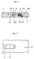
- Fig. 3 shows the section through the tube wall opening 4 according to FIG. 2.
- the locking piece 5 is embedded, so that the locking element 3 can no longer come out of its seat in the receiving chamber by vibration or rotation of the tubes.
Abstract
Description
Die Erfindung betrifft eine Rohrverbindung zweier Vortriebsrohre oder dergleichen, bei der bei zusammengesetzten Rohren ein auf einer Seite des einen Rohres ausgebildetes Steckende in ein auf einer Seite des zweiten Rohres ausgebildetes Muffenende eingreift, wobei am Steck- bzw. am Muffenende die Wandstärke der Rohre durch eine radial nach innen bzw. radial nach außen abgesetzte Stufe reduziert ist und die Stufenhöhe der Stufe am Steckende mit der Stufenhöhe der Stufe am Muffenende übereinstimmt, wobei bei zusammengesetzten Rohren zwischen dem freien Ende des Steckendes und dem benachbarten Bereich des Muffenendes ein flexibles Dichtelement eingesetzt ist, wobei mit Abstand vom freien Ende des Steckendes und mit Abstand vom freien Ende des Muffenendes am äußeren Umfang des Steckendes und am inneren Umfang des Muffenendes jeweils eine Aufnahmenut zur Bildung einer Aufnahmekammer eingelassen ist, und wobei in die durch die Aufnahme nuten gebildete Aufnahmekammer bei zusammengesetzten Rohren ein über eine Rohrwandöffnung von außen eingesetztes Sperrelement eingelassen ist.The invention relates to a pipe connection of two jacking pipes or the like, in which, in the case of assembled pipes, a plug end formed on one side of the one pipe engages in a socket end formed on one side of the second pipe, the wall thickness of the pipes at the plug or the socket end radially inward or radially outward step is reduced and the step height of the step at the plug end corresponds to the step height of the step at the socket end, a flexible sealing element being used in the case of assembled pipes between the free end of the plug end and the adjacent area of the socket end, wherein at a distance from the free end of the plug end and at a distance from the free end of the socket end on the outer circumference of the plug end and on the inner circumference of the socket end, a receiving groove is formed to form a receiving chamber, and wherein in the receiving chamber formed by the receiving grooves when put together ten pipes is inserted a blocking element inserted from the outside through a pipe wall opening.
Eine gattungsgemäße Rohrverbindung zweier Vortriebsrohre ist durch die DE 38 14 913 C2 bekannt. Bei dieser Verbindung ist die axiale Länge des abgestuften Bereichs des Steckendes kürzer als die axiale Länge des abgestuften Bereichs des Muffenendes. In die dadurch gebildete Öffnung ist bei zusammengesetzten Rohrteilen das Dichtelement eingelassen, welches einerseits seitlich vom freien Ende des Steckendes und andererseits von der Anlageschulter des Muffenendes eingeschlossen ist. Diese Lage des Dichtringes hat zur Folge, daß beim Zusammenführen von Muffenende und Steckende der Dichtring axial so weit komprimiert werden muß, bis die Aufnahmenuten für das Sperrelement deckungsgleich übereinanderliegen. Dazu sind - je nach auftretenden Toleranzen - mitunter hohe axiale Presskräfte erforderlich, die nicht in jeder Lage aufgebracht werden können. Auch führte die spezielle Lage der Dichtung schon bei relativ großen Biegeradien zu Undichtigkeiten in der Verbindung der beiden Rohrteile, die beim Einsatz als wasserführende Rohrleitung nicht toleriert werden konnten.A generic pipe connection of two jacking pipes is known from DE 38 14 913 C2. With this connection, the axial length of the stepped region of the plug end is shorter than the axial length of the stepped region of the socket end. In the opening thus formed, the sealing element is inserted in the case of assembled pipe parts, which is enclosed on the one hand laterally from the free end of the plug end and on the other hand by the contact shoulder of the sleeve end. The result of this position of the sealing ring is that when the sleeve end and the plug end are brought together, the sealing ring must be compressed axially until the receiving grooves for the locking element lie congruently one above the other. Depending on the tolerances that occur, this sometimes requires high axial pressing forces that cannot be applied in every position. Even the special position of the seal led to leaks in the connection of the two pipe parts, even at relatively large bending radii, which could not be tolerated when used as a water-bearing pipe.
Hier setzt die Erfindung ein, die es sich zur Aufgabe gestellt hat, die hohen Verpresskräfte bei nach dem Stand der Technik zusammengesetzten Rohrteilen entscheidend zu reduzieren und die Dichtigkeit der geschaffenen Rohrverbindung zwischen zwei Vortriebsrohren zu erhöhen. Erfindungsgemäß wird dazu vorgeschlagen, daß der abgestufte Bereich des Steckendes an seinem freien Ende eine weitere Abstufung aufweist, welche in ihrer Tiefe der Aufnahmenut entspricht, daß in dem der weiteren Abstufung gegenüberliegenden Wandbereich des Muffenendes eine der Tiefe der weiteren Abstufung entsprechende Nut eingelassen ist, und daß in die Nut des Muffenendes ein Lippendichtring eingesetzt ist. Dabei ist der lichte Aufnahmeraum der Nut vom Endbereich der weiteren Abstufung des Steckendes übergriffen.This is where the invention comes in, which has set itself the task of significantly reducing the high pressing forces in the case of pipe parts assembled according to the prior art and increasing the tightness of the pipe connection created between two jacking pipes. According to the invention it is proposed that the stepped region of the plug end has a further gradation at its free end, which corresponds in depth to the receiving groove, that a groove corresponding to the depth of the further gradation is embedded in the wall region of the socket end opposite the further gradation, and that a lip seal is inserted in the groove of the sleeve end. The clear receiving space of the groove is overlapped by the end region of the further gradation of the plug end.
Die Vorteile dieser Ausführungsform werden in erster Linie darin gesehen, daß die beiden zusammenzufügenden Rohrteile ohne mechanische Hilfsmittel per Hand so weit zusammengesteckt werden können, daß die Aufnahmenuten für das Sperrelement deckungsgleich übereinander liegen, und daß der als Sperrelement dienende Verriegelungsstab ohne weitere Hilfsmittel über die Rohröffnung in die durch die Aufnahmenuten gebildete Aufnahmekammer eingeschoben werden kann.The advantages of this embodiment are seen primarily in the fact that the two pipe parts to be joined together can be pushed together by hand without mechanical aids so that the receiving grooves for the locking element lie congruently one above the other, and that the locking rod serving as a locking element can be passed over the pipe opening without any further aids can be inserted into the receiving chamber formed by the receiving grooves.
Darüber hinaus wird aufgrund der Funktionsweise der erfindungsgemäßen Lippendichtung die Dichtigkeit des Systems auch bei erheblich kleineren Biegeradien beibehalten, als sie beim Stand der Technik noch zulässig waren.In addition, due to the functioning of the lip seal according to the invention, the tightness of the system is maintained even with considerably smaller bending radii than were still permitted in the prior art.
Ein weiterer wesentlicher Vorteil gegenüber da Stand der Technik wird darin gesehen, daß der abgestufte Bereich des Steckendes und der abgestufte Bereich des Muffenendes in ihrer jeweiligen axialen Länge gleichgehalten sind, d.h. daß der eine Bereich nicht mehr kürzer gehalten ist als der andere, um das Dichtelement einsetzen zu können. Diese neue Gestaltungsweise von Muffenende und Spitzende erlaubt ein gegenseitiges Abstützen in der erfindungsgemäßen Verbindung, wodurch die axiale Druckbelastung gegenüber der Verbindung nach dem Stand der Technik um ca. 50% erhöht werden kann.Another significant advantage over the prior art is seen in the fact that the stepped area of the plug end and the stepped area of the sleeve end are kept the same in their respective axial lengths, ie that one area is no longer kept shorter than the other around the sealing element to be able to use. This new design of the socket end and spigot end allows mutual support in the connection according to the invention, as a result of which the axial pressure load can be increased by approximately 50% compared to the connection according to the prior art.
Die gegenseitige Abstützung zwischen Muffenende und Steckende stabilisiert den Verbindungsbereich der beiden Rohrteile und führt damit zu einer Erhöhung der Dichtungsstabilität beim Bohrvortrieb. Bei einer Zugbelastung entwickelt diese neue Verbindungsform dagegen ihre maximale Flexibilität. Diesem Vorteil dient auch die Übergreifung des lichten Aufnahmeraums der Nut durch den Endbereich der weiteren Abstufung des Steckendes.The mutual support between the socket end and the plug end stabilizes the connection area of the two pipe parts and thus leads to an increase in the sealing stability during drilling. In contrast, this new form of connection develops its maximum flexibility when subjected to a tensile load. This advantage also serves the overlapping of the clear receiving space of the groove through the end region of the further gradation of the plug end.
Es hat sich als zweckmäßig erwiesen, daß der Lippendichtring mit seiner flexiblen Lippe zur weiteren Abstufung im abgestuften Bereich des Steckendes ausgerichtet ist. Auf diese Weise entwickelt die Dichtungslippe beim Zusammenstecken von Steckende und Muffenende ihre höchste Dichtwirkung.It has proven to be expedient for the lip sealing ring with its flexible lip to be aligned for further gradation in the stepped region of the plug end. In this way, the sealing lip develops its highest sealing effect when the plug end and socket end are put together.
Es hat sich weiter als vorteilhaft erwiesen, daß in die Öffnung der Aufnahmekammer zur Sicherung der Verbindungslage des Sperrelementes ein Verriegelungsstück eingesetzt ist, welches in form- oder kraftschlüssiger Verbindung in seinem Verriegelungssitz in der Öffnung gehalten ist. Hierbei ist ausschlaggebend, daß Vortriebsrohre in der Regel im Bohrvortrieb verlegt werden. Dabei werden die Rohre von einer Startgrube ausgehend in den anstehenden Boden vorgepresst, wobei gleichzeitig eine im Rohr rotierende Förderschnecke das Erdreich von der Stirnseite des Rohrverbundes in die Startgrube abfördert. Dabei hat die Förderschnecke im Rohr ein gewisses Spiel gegenüber dem Rohrinnendurchmesser und es kann beispielsweise bei der Verklemmung von Steinen in diesem Spielbereich zur Rotation einzelner Rohrabschnitte im Rohrverbund kommen. Diese Rotationsmöglichkeit ist gewollt, da aufgrund der hohen auftretenden Drehmomente eine nicht drehbare Verbindung an der schwächsten Stelle, nämlich in den Steckbereichen, brechen würde.It has also proven to be advantageous that a locking piece is inserted into the opening of the receiving chamber to secure the connection position of the locking element, which is held in its locking seat in the opening in a positive or non-positive connection. The decisive factor here is that jacking pipes are usually laid in drilling. The pipes are pressed from a starting pit into the existing soil, while a screw conveyor rotating in the pipe simultaneously transports the soil from the front of the pipe assembly into the starting pit. The screw conveyor in the tube has a certain amount of play in relation to the inside diameter of the tube and, for example, the jamming of stones in this play area can result in the rotation of individual tube sections in the tube assembly. This possibility of rotation is wanted because, due to the high torques that occur, a non-rotatable connection would break at the weakest point, namely in the plug-in areas.
Diese gewollte Rotation einzelner Rohrteile führt dazu, daß der Verriegelungsstab tangential aus der Einführungsöffnung mehr und mehr herausgeschoben wird. Die Kräfte, die dazu führen, resultieren aus der Reibung des Verriegelungsstabes im Nutengrund zwischen Spitzende und Muffe. Wenn der Verriegelungsstab nicht mehr als Sperrelement zwischen Muffe und Steckende zweier Rohrteile wirken kann, ist die Rohrverbindung in diesem Bereich nicht mehr zugkraftschlüssig und es können sich einzelne Rohrteile während des Einziehens separieren. Auch beim Bohrvortrieb ergeben sich in diesem Fall Schwachpunkte in der Druckbelastung der Verbindung, da das verriegelte gegenseitige Abstützen von Muffe und Spitzende nicht mehr gewährleistet ist. Bei verfahrensbedingten Zugbelastungen können sich außerdem die Rohre bei nicht mehr gewährleisteter, längskraftschlüssiger Verriegelung separieren.This intentional rotation of individual pipe parts leads to the locking rod being pushed more and more tangentially out of the insertion opening. The forces that result from this result from the friction of the locking rod in the groove base between the spigot end and the sleeve. If the Locking rod can no longer act as a locking element between the socket and the plug end of two pipe parts, the pipe connection in this area is no longer tractive and individual pipe parts can separate during the pulling in. In this case, too, there are weak points in the pressure load of the connection when drilling, since the locked mutual support of the socket and spigot end is no longer guaranteed. In the case of process-related tensile loads, the tubes can also separate if the locking is no longer guaranteed, which is a positive locking.
Gegen den geschilderten Nachteil schafft das erfindungsgemäße Verriegelungsstück Abhilfe, welches sich aufgrund seiner geometrischen Form durch eine Presspassung oder mittels kraftschlüssiger Verbindung in die Einführöffnung des Verriegelungsstabes einsetzen läßt und auf diese Weise das Herausdrehen des Verriegelungsstabes beim Vortrieb verhindert. Das Verriegelungsstück kann dabei in verschiedenen geometrischen Formen durch Rasterungen, Nasen oder Riefungen mit da Profil der Einführungsöffnung eine formschlüssige Verbindung eingehen, wodurch die Lage des Verriegelungsstabes in jeder Lage gesichert wird.Against the described disadvantage, the locking piece according to the invention provides a remedy which, due to its geometric shape, can be inserted into the insertion opening of the locking rod by means of a press fit or by means of a non-positive connection and in this way prevents the locking rod from being unscrewed during the advance. The locking piece can enter into a positive connection in various geometrical shapes by means of grids, lugs or grooves with the profile of the insertion opening, whereby the position of the locking rod is secured in any position.
Das Verriegelungsstück kann auch aus elastischem Material gestaltet sein und eine kraftschlüssige Verbindung mit dem Umfang der Rohrwandöffnung eingehen, wobei das Verriegelungsstück in der Rohrwandöffnung gestaucht wird. Hierbei können alle denkbaren elastischen Materialien eingesetzt werden, z.B. Polyethylen oder eine Gummimischung, die aber für die geforderte Lagesicherheit eine hohe Shore-A-Härte von wenigstens 60 aufweisen muß.The locking piece can also be made of elastic material and enter into a non-positive connection with the circumference of the tube wall opening, the locking piece being compressed in the tube wall opening. All conceivable elastic materials can be used, e.g. Polyethylene or a rubber compound, which must have a high Shore A hardness of at least 60 for the required positional security.
In jedem Fall muß sich die Form des Verriegelungsstückes an der Form der vorhandenen Rohrwandöffnung für den als Sperrelement eingesetzten Verriegelungsstab orientieren. So kann bei dickwandigen Rohren der Querschnitt der Rohrwandöffnung für den Verriegelungsstab rund sein oder ein Rechteckprofil aufweisen. Bei dünneren Rohrwänden bieten sich für die tangentiale Rohrwandöffnung schlitzförmige Gestaltungsformen an, die dann entsprechend geformte Verriegelungsstücke erfordern.In any case, the shape of the locking piece must be based on the shape of the existing tube wall opening for the locking rod used as a locking element. In the case of thick-walled pipes, the cross-section can be the tube wall opening for the locking rod be round or have a rectangular profile. In the case of thinner tube walls, slot-like designs are available for the tangential tube wall opening, which then require correspondingly shaped locking pieces.
In der Zeichnung sind Ausführungsbeispiele der erfindungsgemäßen Rohrverbindung schematisch dargestellt; es zeigt:
- Fig. 1 einen Schnitt durch die Rohrverbindung mit Steckende und Muffenende.
- Fig. 2 eine Draufsicht auf die Rohrwandöffnung mit Verriegelungsstück.
- Fig. 3 einen Schnitt durch die Rohrwandöffnung gemäß Fig. 2.
- Fig. 1 shows a section through the pipe connection with plug end and sleeve end.
- Fig. 2 is a plan view of the tube wall opening with a locking piece.
- 3 shows a section through the tube wall opening according to FIG. 2.
Fig. 1 zeigt den Schnitt durch die Verbindung der beiden Rohre 1 mit dem abgestuften Bereich des Steckendes 12 und dem entsprechend abgestuften Bereich des Muffenendes 11. Der abgestufte Bereich des Steckendes 12 besitzt an seinem freien Ende eine weitere Abstufung 121, welche in ihrer Tiefe der Tiefe der Aufnahmenut 122 für das Sperrelement entspricht. In dem der weiteren Abstufung 121 gegenüberliegenden Wandbereich des Muffenendes 11 ist eine der Tiefe der weiteren Abstufung 121 entsprechende Nut 111 eingelassen. Der lichte Aufnahmeraum der Nut 111 ist in der gezeigten Darstellung vom Endbereich 1211 der weiteren Abstufung 121 des Steckendes 12 übergriffen. In die Nut 111 des Muffenendes 11 ist der Lippendichtring 2 eingesetzt. Der Lippendichtring 2 ist so ausgerichtet, daß er mit seiner flexiblen Lippe 21 zur weiteren Abstufung 121 im abgestuften Bereich des Steckendes 12 ausgerichtet ist. Der Aufnahmenut 122 im Steckende 12 gegenüberliegend ist eine entsprechende Aufnahmenut 112 im abgestuften Bereich des Muffenendes 11 eingeformt. In die durch die Aufnahmenuten 112, 122 gebildete Aufnahmekammer ist das Sperrelement 3 eingesetzt, wodurch die Verbindung zwischen den beiden Rohren 1 verriegelt ist.Fig. 1 shows the section through the connection of the two
In Fig. 2 ist im Teilschnitt die Draufsicht auf die Rohrwandöffnung 4 im Bereich des abgestuften Muffenendes 11 dargestellt. Die Rohrwandöffnung 4 ist in der gezeigten Darstellung eine Art Langloch, welches die durch die Aufnahmenuten 112, 122 gebildete Aufnahmekammer für das Sperrelement 3 mit der Außenatmosphäre verbindet. Über die Rohrwandöffnung 4 wird das Sperrelement 3 in die durch die Aufnahmenuten 112, 122 gebildete Aufnahmekammer eingeschoben. Nach diesem Einschieben wird die Rohrwandöffnung 4 wenigstens teilweise durch das Verriegelungsstück 5 verschlossen. Das Verriegelungsstück 5 verhindert das Austreten des Sperrelementes 3 aus seinem Verriegelungssitz in der durch die Aufnahmenuten 112, 122 gebildeten Aufnahmekammer durch Vibration oder Rotation von einzelnen Rohren bei der Verlegung.2 shows a partial section of the top view of the pipe wall opening 4 in the region of the
Fig. 3 zeigt den Schnitt durch die Rohrwandöffnung 4 gemäß Fig. 2. In die Rohrwandöffnung 4 ist das Verriegelungsstück 5 eingelassen, so daß das Sperrelement 3 durch Vibration oder Rotation der Rohre 1 nicht mehr aus seinem Sitz in der Aufnahmekammer heraustreten kann.Fig. 3 shows the section through the tube wall opening 4 according to FIG. 2. In the tube wall opening 4, the
Claims (4)
Applications Claiming Priority (2)
| Application Number | Priority Date | Filing Date | Title |
|---|---|---|---|
| DE29608706U DE29608706U1 (en) | 1996-05-14 | 1996-05-14 | Pipe connection |
| DE29608706U | 1996-05-14 |
Publications (3)
| Publication Number | Publication Date |
|---|---|
| EP0807782A2 true EP0807782A2 (en) | 1997-11-19 |
| EP0807782A3 EP0807782A3 (en) | 1998-04-15 |
| EP0807782B1 EP0807782B1 (en) | 2001-05-23 |
Family
ID=8023949
Family Applications (1)
| Application Number | Title | Priority Date | Filing Date |
|---|---|---|---|
| EP97106036A Expired - Lifetime EP0807782B1 (en) | 1996-05-14 | 1997-04-12 | Pipe joint |
Country Status (3)
| Country | Link |
|---|---|
| EP (1) | EP0807782B1 (en) |
| DE (2) | DE29608706U1 (en) |
| DK (1) | DK0807782T3 (en) |
Cited By (1)
| Publication number | Priority date | Publication date | Assignee | Title |
|---|---|---|---|---|
| US20160177785A1 (en) * | 2014-12-22 | 2016-06-23 | Rolls-Royce Plc | Joint assembly and a method of using the same |
Families Citing this family (2)
| Publication number | Priority date | Publication date | Assignee | Title |
|---|---|---|---|---|
| US9441651B2 (en) | 2012-12-10 | 2016-09-13 | Rolls-Royce Plc | Joint assembly and method of using the same |
| GB201915814D0 (en) | 2019-10-31 | 2019-12-18 | Rolls Royce Plc | Joint assembly |
Citations (5)
| Publication number | Priority date | Publication date | Assignee | Title |
|---|---|---|---|---|
| DE1525525A1 (en) * | 1965-04-09 | 1969-07-31 | Btr Industries Ltd | Detachable pipe coupling |
| US4293148A (en) * | 1979-02-22 | 1981-10-06 | Fmc Corporation | Pile connector |
| DE3814913A1 (en) * | 1988-05-03 | 1989-11-16 | Rehau Ag & Co | PIPE CONNECTION |
| EP0438296A2 (en) * | 1990-01-17 | 1991-07-24 | Hachiro Inoue | Interface joint for cylindrical members |
| EP0556545A1 (en) * | 1992-02-21 | 1993-08-25 | BODE GmbH | Sealing ring for an insert sleeve connection |
Family Cites Families (4)
| Publication number | Priority date | Publication date | Assignee | Title |
|---|---|---|---|---|
| DE2106106A1 (en) * | 1971-02-09 | 1972-08-24 | Eternit Ag | Pipe connection |
| DE3822276A1 (en) * | 1987-07-24 | 1989-02-02 | Bohrtec Gmbh & Co Kg Fuer Bohr | Advancement pipe |
| DE8805742U1 (en) * | 1988-04-30 | 1988-06-16 | Rehau Ag + Co, 8673 Rehau, De | |
| DE3844045A1 (en) * | 1988-12-28 | 1990-07-05 | Rehau Ag & Co | PIPE CONNECTION |
-
1996
- 1996-05-14 DE DE29608706U patent/DE29608706U1/en not_active Expired - Lifetime
-
1997
- 1997-04-12 DE DE59703580T patent/DE59703580D1/en not_active Expired - Fee Related
- 1997-04-12 EP EP97106036A patent/EP0807782B1/en not_active Expired - Lifetime
- 1997-04-12 DK DK97106036T patent/DK0807782T3/en active
Patent Citations (5)
| Publication number | Priority date | Publication date | Assignee | Title |
|---|---|---|---|---|
| DE1525525A1 (en) * | 1965-04-09 | 1969-07-31 | Btr Industries Ltd | Detachable pipe coupling |
| US4293148A (en) * | 1979-02-22 | 1981-10-06 | Fmc Corporation | Pile connector |
| DE3814913A1 (en) * | 1988-05-03 | 1989-11-16 | Rehau Ag & Co | PIPE CONNECTION |
| EP0438296A2 (en) * | 1990-01-17 | 1991-07-24 | Hachiro Inoue | Interface joint for cylindrical members |
| EP0556545A1 (en) * | 1992-02-21 | 1993-08-25 | BODE GmbH | Sealing ring for an insert sleeve connection |
Cited By (2)
| Publication number | Priority date | Publication date | Assignee | Title |
|---|---|---|---|---|
| US20160177785A1 (en) * | 2014-12-22 | 2016-06-23 | Rolls-Royce Plc | Joint assembly and a method of using the same |
| US10100961B2 (en) * | 2014-12-22 | 2018-10-16 | Rolls-Royce Plc | Joint assembly and a method of using the same |
Also Published As
| Publication number | Publication date |
|---|---|
| DE59703580D1 (en) | 2001-06-28 |
| EP0807782A3 (en) | 1998-04-15 |
| DK0807782T3 (en) | 2001-08-06 |
| EP0807782B1 (en) | 2001-05-23 |
| DE29608706U1 (en) | 1996-08-08 |
Similar Documents
| Publication | Publication Date | Title |
|---|---|---|
| EP1972844B1 (en) | Fitting for water pipes | |
| EP2933542B1 (en) | Connection for corrugated pipes | |
| EP3428498B1 (en) | Pipe, in particular plastic pipe for drain pipes | |
| EP2724065B1 (en) | Hose nipple and corresponding hose arrangement | |
| EP0932789B1 (en) | Pipe connection | |
| DE4030323A1 (en) | PIPE PRESSURE COUPLING | |
| EP1154187A2 (en) | Compression fitting for plastic composite pipes | |
| WO2008009573A1 (en) | Sleeve, and combination of a sleeve and a pressing tool | |
| DE2118781A1 (en) | Pipe seal | |
| EP1288554A1 (en) | Connection means for a pipe | |
| DE4117932C2 (en) | ||
| DE19929010C1 (en) | Pipe connection has a molded plastics body to hold the pipe connector with a press sleeve and a support sleeve with a free zone to allow a slight bend or tilt in the assembly | |
| EP0807782A2 (en) | Pipe joint | |
| DE3104518A1 (en) | Connecting fitting | |
| AT294503B (en) | Pipe connection | |
| WO2001038773A1 (en) | Connector fitting for a high pressure hose | |
| DE19728137C1 (en) | Plug connection for pipe conduits | |
| EP3869077A1 (en) | Tube adapter | |
| DE102007060490B4 (en) | hose connection | |
| EP2476939A2 (en) | Connector for connecting a tube end | |
| EP3112736A1 (en) | Pull-out protection | |
| AT405969B (en) | DEVICE FOR CONNECTING A PIPE TO A CHASSIS FLOOR | |
| WO2000060267A1 (en) | Device for connecting pipe sections | |
| EP0863357A2 (en) | Pipe connection | |
| AT265770B (en) | Self-sealing pipe coupling |
Legal Events
| Date | Code | Title | Description |
|---|---|---|---|
| PUAI | Public reference made under article 153(3) epc to a published international application that has entered the european phase |
Free format text: ORIGINAL CODE: 0009012 |
|
| AK | Designated contracting states |
Kind code of ref document: A2 Designated state(s): DE DK FR SE |
|
| PUAL | Search report despatched |
Free format text: ORIGINAL CODE: 0009013 |
|
| AK | Designated contracting states |
Kind code of ref document: A3 Designated state(s): DE DK FR SE |
|
| 17P | Request for examination filed |
Effective date: 19980430 |
|
| 17Q | First examination report despatched |
Effective date: 19981106 |
|
| GRAG | Despatch of communication of intention to grant |
Free format text: ORIGINAL CODE: EPIDOS AGRA |
|
| GRAG | Despatch of communication of intention to grant |
Free format text: ORIGINAL CODE: EPIDOS AGRA |
|
| GRAH | Despatch of communication of intention to grant a patent |
Free format text: ORIGINAL CODE: EPIDOS IGRA |
|
| GRAH | Despatch of communication of intention to grant a patent |
Free format text: ORIGINAL CODE: EPIDOS IGRA |
|
| GRAA | (expected) grant |
Free format text: ORIGINAL CODE: 0009210 |
|
| AK | Designated contracting states |
Kind code of ref document: B1 Designated state(s): DE DK FR SE |
|
| REF | Corresponds to: |
Ref document number: 59703580 Country of ref document: DE Date of ref document: 20010628 |
|
| REG | Reference to a national code |
Ref country code: DK Ref legal event code: T3 |
|
| ET | Fr: translation filed | ||
| PLBE | No opposition filed within time limit |
Free format text: ORIGINAL CODE: 0009261 |
|
| STAA | Information on the status of an ep patent application or granted ep patent |
Free format text: STATUS: NO OPPOSITION FILED WITHIN TIME LIMIT |
|
| PGFP | Annual fee paid to national office [announced via postgrant information from national office to epo] |
Ref country code: SE Payment date: 20020514 Year of fee payment: 6 |
|
| PGFP | Annual fee paid to national office [announced via postgrant information from national office to epo] |
Ref country code: DK Payment date: 20020515 Year of fee payment: 6 |
|
| 26N | No opposition filed | ||
| PGFP | Annual fee paid to national office [announced via postgrant information from national office to epo] |
Ref country code: FR Payment date: 20030313 Year of fee payment: 7 |
|
| PGFP | Annual fee paid to national office [announced via postgrant information from national office to epo] |
Ref country code: DE Payment date: 20030318 Year of fee payment: 7 |
|
| PG25 | Lapsed in a contracting state [announced via postgrant information from national office to epo] |
Ref country code: SE Free format text: LAPSE BECAUSE OF NON-PAYMENT OF DUE FEES Effective date: 20030413 |
|
| PG25 | Lapsed in a contracting state [announced via postgrant information from national office to epo] |
Ref country code: DK Free format text: LAPSE BECAUSE OF NON-PAYMENT OF DUE FEES Effective date: 20030430 |
|
| EUG | Se: european patent has lapsed | ||
| REG | Reference to a national code |
Ref country code: DK Ref legal event code: EBP |
|
| PG25 | Lapsed in a contracting state [announced via postgrant information from national office to epo] |
Ref country code: DE Free format text: LAPSE BECAUSE OF NON-PAYMENT OF DUE FEES Effective date: 20041103 |
|
| PG25 | Lapsed in a contracting state [announced via postgrant information from national office to epo] |
Ref country code: FR Free format text: LAPSE BECAUSE OF NON-PAYMENT OF DUE FEES Effective date: 20041231 |
|
| REG | Reference to a national code |
Ref country code: FR Ref legal event code: ST |