EP0852407A2 - Adaptive antenna - Google Patents
Adaptive antenna Download PDFInfo
- Publication number
- EP0852407A2 EP0852407A2 EP98300135A EP98300135A EP0852407A2 EP 0852407 A2 EP0852407 A2 EP 0852407A2 EP 98300135 A EP98300135 A EP 98300135A EP 98300135 A EP98300135 A EP 98300135A EP 0852407 A2 EP0852407 A2 EP 0852407A2
- Authority
- EP
- European Patent Office
- Prior art keywords
- signal
- signals
- antenna
- antenna elements
- adaptive
- Prior art date
- Legal status (The legal status is an assumption and is not a legal conclusion. Google has not performed a legal analysis and makes no representation as to the accuracy of the status listed.)
- Granted
Links
Images


Classifications
-
- H—ELECTRICITY
- H01—ELECTRIC ELEMENTS
- H01Q—ANTENNAS, i.e. RADIO AERIALS
- H01Q3/00—Arrangements for changing or varying the orientation or the shape of the directional pattern of the waves radiated from an antenna or antenna system
- H01Q3/26—Arrangements for changing or varying the orientation or the shape of the directional pattern of the waves radiated from an antenna or antenna system varying the relative phase or relative amplitude of energisation between two or more active radiating elements; varying the distribution of energy across a radiating aperture
- H01Q3/2605—Array of radiating elements provided with a feedback control over the element weights, e.g. adaptive arrays
- H01Q3/2652—Self-phasing arrays
-
- H—ELECTRICITY
- H01—ELECTRIC ELEMENTS
- H01Q—ANTENNAS, i.e. RADIO AERIALS
- H01Q3/00—Arrangements for changing or varying the orientation or the shape of the directional pattern of the waves radiated from an antenna or antenna system
- H01Q3/26—Arrangements for changing or varying the orientation or the shape of the directional pattern of the waves radiated from an antenna or antenna system varying the relative phase or relative amplitude of energisation between two or more active radiating elements; varying the distribution of energy across a radiating aperture
- H01Q3/2605—Array of radiating elements provided with a feedback control over the element weights, e.g. adaptive arrays
- H01Q3/2611—Means for null steering; Adaptive interference nulling
Definitions
- the present invention relates to an adaptive antenna for a base station and a terminal unit used in for example a radio communication system.
- An adaptive antenna suppresses undesired signal such as delayed signals and interference signals that a base station or a terminal unit has received so as to increase the data transmission rate and the number of users.
- energy of delayed signals through multipath is combined as desired signals and thereby the signal-to-noise ratio of the desired signal is improved.
- signals received by a plurality of omni-directional antenna elements 101, 102, and 103 are sent to A/D converters 104, 105, and 106.
- the A/D converters 104, 105, and 106 convert the received signals into digital signals and distribute the digital signals to a plurality of adaptive signal processing portions 107, 108, and 109.
- the output signals of the A/D converters 104, 105, and 106 are sent to respective weighting units 110.
- the output signals of the weighting units 110 are sent to respective adding units 111.
- the adding units 111 combine the output signals of the weighting units 110.
- a weighting amount of each weighting unit 110 is designated by a weight control circuit 113.
- the weight control circuit 113 designate weighting amounts of the weighting units 110 so as to emphasize a signal component that has a strong correlation with a reference signal and suppress the other signal components as interference components.
- the weight control circuit 113 controls the weighting amounts that the adaptive signal processing portions 107, 108, and 109 designate in such a manner that a particular adaptive signal processing portion extracts a first incoming signal component (that does not have a delay) and other adaptive signal processing portions extract signal components that have delays.
- a combining unit 112 extracts a pure signal of which delayed signals and interference signals are removed from a received signal that consist of a first incoming signal and delayed signals.
- the adaptive antenna requires (L x N) weighting units.
- the number of weighting units affects the number of calculations of the weighting amounts of the controlling circuit.
- the circuit structure becomes complicated.
- An object of the present invention is to provide an adaptive antenna that allows the number of weighting units to be remarkably decreased and thereby the structure thereof to be simplified.
- Another object of the present invention is to provide an adaptive antenna that allows the weighting process to be quickly performed, thereby quickly adapting to the fluctuation of the transmission environment of the radio signal.
- a further object of the present invention is to provide an adaptive antenna that can remarkably suppress an interference signal from taking place.
- the present invention is an adaptive antenna that comprises a plurality of antenna elements with different directivity, an estimating means for estimating states of received signals of the antenna elements for each of delay times that have been designated, a selecting means for selecting a part of the antenna elements for each of the delay times corresponding to the estimated result, a weighting means for determining the received signals of the part of said antenna elements selected by said selecting means by relevant weights, first combining means for multiplying the received signals to which relevant weights have been determined for each of the delay time and summing the weighted signals, compensating means for compensating the time lag, or time delay of each of the received signals for each of the delay times, and second combining means for combining the compensated signals for the delay times.
- an adaptive antenna of the present invention a part of antenna elements is selected for each delay times corresponding to the estimated result of a received signal of each antenna element.
- the received signals of each selected antenna element is weighted.
- a pure signal of which a interference signal component is removed from a received signal in each of delay times is obtained.
- the total process amount for designating weights to received signals can be remarkably reduced in comparison with that of the related art reference.
- Fig. 1 is a schematic diagram showing the structure of an adaptive antenna according to a first embodiment of the present invention.
- N antenna elements 1 1 , 1 2 , ..., and 1 N that have respective directivity have respective beam directions.
- the adaptive antenna according to the present invention can be accomplished with omni-directional antenna elements.
- the antenna elements 1 1 , 1 2 , ..., and 1 N are connected to delay profile measuring units 2 1 , 2 2 , ..., and 2 N , respectively.
- the delay profile measuring units 2 1 , 2 2 , ..., and 2 N generate delay profiles of the antenna elements 1 1 , 1 2 , ..., and 1 N with a correlating process using a known reference symbol placed in a transmission signal.
- the delay profile measuring units 2 1 , 2 2 , ..., and 2 N extract signal components for L different delay times from the received signals and supply the extracted signal components for the L different delay times to antenna selecting units 3 1 , 3 2 , ..., and 3 L corresponding to the delay times.
- the antenna selecting units 3 1 , 3 2 , ..., and 3 L select received signals of K (where K ⁇ N) antenna elements from the received signals of the N antenna elements 1 1 , 1 2 , ..., 1 N and supply the selected signals to adaptive signal processing portions 4 1 , 4 2 , ..., and 4 L .
- the adaptive signal processing portion 4 1 process a signal component with no delay time (namely, a first incoming signal).
- the other adaptive signal processing portions 4 2 , ..., and 4 L process signal components with respective delay times (delayed signals).
- the signals processed by the adaptive signal processing portions 4 1 , 4 2 , ..., and 4 N are combined by a combining unit 6.
- the antenna elements 1 1 to 1 8 are disposed at positions on a circle.
- the antenna elements 1 1 to 1 8 are sector beam antennas that radiate with the maximum amount from the center thereof.
- the antenna elements 1 1 to 1 8 with such directivity suppresses interference signal incoming from first directions other than DOA of a desired signal, thereby preventing the first incoming signal from degrading.
- Fig. 2 is a schematic diagram showing the relation between signals that antenna elements 1 1 to 1 8 receive and delay profiles thereof estimated by delay profile measuring units 2 1 , 2 2 , ..., and 2 N .
- the horizontal axis represents delay time
- the vertical axis represents the power of the received signal. It is assumed that signals to be measured are a first incoming signal, a one-symbol-delayed signal, and a two-symbol-delayed signal.
- the K received signals for each of delay times are sent to the adaptive signal processing portions 4 1 , 4 2 , ..., and 4 L corresponding to the respective delay times.
- the antenna selecting unit 3 1 selects the antenna elements 1 1 , 1 2 , and 1 8 with larger signal intensity of the received first incoming signal.
- the antenna selecting unit 3 2 selects the antenna elements 1 1 , 1 2 , and 1 3 with larger signal intensity of the one-symbol-delayed signal.
- the antenna selecting unit 3 L selects the antenna elements 1 3 , 1 4 , and 1 5 with larger signal intensity of the two-symbol-delayed signal.
- Fig. 3 is a schematic diagram showing the structure of an adaptive signal processing portion.
- each of the adaptive signal processing portions 4 1 , 4 2 , ..., and 4 L comprises K weighting units 7, an adding unit 8, and a weight control circuit 9.
- the weighting units 7 designate weights to received signals of the relevant antenna selecting unit (3 1 , 3 2 , ..., or 3 L ).
- the adding unit 8 combines the received signals that have been weighted by the weighting units 7 and supplies the resultant signal to the weight control circuit 9 and the combining unit 6.
- Each of the weighting unit 7 designates a weight to a relevantly received signal by varying the amplitude and phase thereof.
- Each of the weighting units 7 can be accomplished by either a digital signal processing circuit or an analog signal processing circuit.
- each weighting unit 7 can be accomplished with a multiplying unit (mixer) that multiplies a received signal by a weight control signal or a variable attenuator/variable phase shifter that vary the amplitude/phase of a received signal.
- the weight control circuit 9 defines weights that the K weighting units 7 designate to respectively received signals . In other words, the weight control circuit 9 determines weights that the weighting units 7 designate to respectively received signals corresponding to the output signal of the adding unit 8 and a predetermined reference signal in such a manner that a desired signal component of the relevant received signal becomes strong and interference signal components become weak.
- the desired signal depends on a circuit. In other words, in a circuit that processes a first incoming signal, the desired signal is a first incoming signal. In a circuit that processes a one-symbol-delayed signal, the desired signal is a one-symbol-delayed signal.
- the weight control circuit 9 in the adaptive signal processing portion 4 1 defines weights that the weighting units 7 designate to the respectively received signals in such a manner that the first incoming signal component of the received signal obtained through the antenna selecting unit 3 1 becomes strong and the other signal components become weak.
- the weight control circuit 9 in the adaptive signal processing portion 4 2 determines weights that the weighting units 7 designates to the respectively received signals in such a manner that the one-symbol-delayed signal component of the received signal obtained through the antenna selecting unit 3 3 becomes strong and the other components become weak. This operation applies to the weight control circuit 9 in the adaptive signal processing portion 4 3 .
- the weight determining method is categorized as LMS (Least Mean Square) algorithm, CMA (Constant Modulus Algorithm), and so forth.
- the adaptive signal processing portions 4 1 , 4 2 , ..., and 4 L shown in Fig. 3 control weights corresponding to the combined received signal.
- the adaptive signal processing portions 4 1 , 4 2 ,..., and 4 L may control weights corresponding to K received signals obtained through the antenna selecting units.
- the adaptive signal processing portions 4 1 , 4 2 , ..., and 4 L output signals of which the desired signal components of the first incoming signal, the one-symbol-delayed signal, and the two-symbol-delayed signal have become strong.
- Output signals of the adaptive signal processing portions 4 2 and 4 3 that process delayed signals are sent to the combining unit 6 through delaying circuits 5 2 and 5 3 , respectively.
- the delaying circuits 5 2 and 5 3 compensate times of the one-symbol-delayed signal and the two-symbol-delayed signal based on the incoming time of the first incoming signal.
- the combining unit 6 combines the first incoming signal directly received from the adaptive signal processing portion 4 1 and the delayed signals received through the delaying circuits 5 2 and 5 3 . Examples of the combining method are coherent combining method and maximum-ratio combining method.
- Fig. 4 is a schematic diagram showing the structure of the adaptive antenna according to the second embodiment.
- Antenna elements 11 1 , 11 2 ,..., and 11 N are connected to L (where N > L) antenna selecting unit 13 1 , 13 2 , .., and 13 L .
- the antenna elements 11 1 , 11 2 , ..., and 11 N are connected to delay profile measuring units 12 1 , 12 2 , ..., and 12 N .
- the delay profile measuring units 12 1 , 12 2 , ..., and 12 N measure respective delay profiles of the antenna elements 11 1 , 11 2 , ..., and 11 N and supplies the measured delay profiles to a controlling portion 10.
- the controlling portion 10 designates antenna selecting conditions of the antenna selecting units 13 1 , 13 2 , ..., and 13 L corresponding to the delay profiles of the antenna elements. In other words, the controlling portion 10 causes the antenna selecting unit 13 1 to select K antennas that receive the first incoming signal. In addition the controlling portion 10 causes the antenna selecting unit 13 2 to select K antennas that receive the one-symbol-delayed signal.
- the received signals of K antenna elements selected by each of the antenna selecting units 13 1 , 13 2 , ..., and 13 L are supplied to adaptive signal processing portions 14 1 , 14 2 , ..., and 14 L , respectively.
- signals of which the powers of desired signal components of the first incoming signal and delayed signals have become strong can be obtained.
- Output signals of the two adaptive signal processing portions 14 2 and 14 3 are supplied to a combining unit 16 through delaying circuits 15 2 and 15 3 , respectively.
- the combining unit 16 combines the first incoming signal received from the adaptive signal processing portion 14 1 and the delayed signals received from the delaying circuits 15 2 and 15 3 and outputs the resultant signal as one received signal.
- the adaptive antenna according to the first and second embodiments combines a first incoming signal component and delayed signal components, thereby obtaining a received signal with a high signal-to-noise ratio.
- the adaptive antenna according to each of the first and second embodiments selects antenna elements with larger power, intensity, or signal-to-noise ratio and designates weights to signals received from the selected antenna elements.
- the number of weighting units 7 can be reduced in comparison with that of the conventional adaptive antenna. Consequently, the adaptive signal process can be effectively performed.
- a received signal with a high signal-to-noise ratio can be obtained.
- the adaptive antenna according to the present invention can be partly modified as follows.
- An antenna selector selects antenna elements whose measured delay profiles exceed a predetermined reference value.
- the difference between the above-described embodiments and this modification is in that the number of antenna elements is not constant.
- the present invention is based on sector beams with different beam directions regarding to the directivity of each antenna elements.
- received signals of a plurality of omni-directional elements are Fourier-transformed, orthogonal multi-beams are formed and thereby an adaptive signal process is performed for the resultant beams in the beam space.
- the present invention can be applied to an adaptive antenna with circuits that Fourier-transform received signals of antenna elements.
- Examples of the Fourier transform method are analog method using lenses or reflectors and FFT (Fast Fourier Transform) method of which digital signals converted from analog signals are Fourier-transformed.
- Received signals of the adaptive antenna according to the present invention can be analog signals or digital signals.
- received signals are digital signals
- output signals of antenna elements are converted into digital signals by A/D converters.
- the adaptive antenna according to the third embodiment features in the selecting method of antenna elements.
- Each antenna selecting unit in the adaptive antenna selects K antenna elements with larger power, intensity, or signal-to-noise ratio of a desired signal for each of delay times.
- each antenna selecting unit selects P (where 1 ⁇ P) antenna elements with larger power, intensity, or signal-to-noise ratio of undesired signal.
- an adaptive antenna tends to form null to the DOA of undesired signal whose level is large and whose correlation with a desired signal is small. Thus, when such antenna elements are selected, undesired signals can be remarkably suppressed.
- an adaptive antenna that has a means that estimates an interference signal will be described.
- This adaptive antenna selects K antenna elements with larger power, intensity, or signal-to-noise ratio of received signals as a desired signal for each of delay times.
- the adaptive antenna selects P (where 1 ⁇ P) antenna elements with larger power, intensity, or signal-to-noise ratio of interference signal signals.
- an adaptive antenna tends to designate null to the DOA of a non-desired signal whose level is large and whose correlation with a desired signal is small. Thus, when such antenna elements are selected, a signal of a non-desired signal can be remarkably suppressed.
- Fig. 5A shows a delay profile r D (t) of a desired signal and a delayed signal of a particular antenna element.
- Fig. 5B shows a delay profile r I (t) of an interference signal.
- Fig. 5D shows a delay profile R'(t) estimated in the above-described correlating process.
- a replica R(t) (not shown) of a combined signal of a desired signal and a delayed signal can be obtained corresponding to the delay profile R'(t).
- a difference signal d(t) of the received signal R(t) and the replica R(t) is composed of an interference signal component, a delayed signal component, and a thermal noise component (that have not been time-decomposed).
- the intensity of the interference signal can be approximately obtained.
- Fig. 5F shows a delay profile R' 0 (t) estimated, which is composed of all delayed signals except for a desired signal at delay time (t 0 ).
- the replica R 0 (t) of a combined signal which is composed corresponding to the estimated delay profile R' 0 (t) is provided, as shown in Fig. 5F, the difference signal d 0 (t) of the received signal R(t) and the replica R 0 (t) is composed of a desired signal component at t 0 , an interference signal component, a delayed signal component (that cannot be fully time-decomposed), and a thermal noise component.
- the adaptive array process is performed with the difference signal d 0 (t) instead of the received signal, the interference signal can be sufficiently suppressed.
- Antenna elements may receive delayed signal in the same direction as a desired signal or in a direction close thereto.
- the adaptive process is performed with d 0 (t) shown in Fig. 5G, delayed signals and interference signals can be remarkably suppressed.
- the adaptive signal processing portion is often structured in such a manner that it successively performs a feed-back process so as to converge the weighting amount of each of the antenna elements.
- a SMI Sample Matrix Inverse
- This method need very large amount of processing (e.g. calculation of inverse matrix), but a stable output signal can be obtained without a dispersion of weighting amounts because there is no feed-back line.
- this adaptive can perform as a diversity that can suppress undesired signals.
- the adaptive antenna according to the present invention can be applied to a receiver of a CDMA (Code Division Multiple Access) system.
- CDMA Code Division Multiple Access
- the path diversity of the CDMA type RAKE receiver and the delay profile estimating technology with a high time-resolution can be directly used.
- the channel capacity of the CDMA system in multi-interference environment can be increased.
- the adaptive antenna according to the present invention can effectively control the directivity.
- TDMA Time Division Multiple Access
- a large allowable interference amount of the system can be designated.
- the repetitive number of cells with the same channel can be decreased, the system capacity can be increased.
- each of elements 1 1 to 1 4 of the adaptive antenna according to the fourth embodiment can generate three beams P 11 , P 12 , ..., P 43 with different directivity. It is assumed that a first incoming signal, a one-symbol-delayed signal, and a two-symbol-delayed signal are received as shown in Fig. 6. In addition, it is assumed that delay profile estimating units (not shown) of the antenna elements estimate powers of received signals.
- the current beams of the individual antenna elements are switched until the next reception time in the following manner.
- the beams of the individual antenna elements are selected in the ascending order (namely, beams P 11 , P 21 , P 31 , and P 41 ) are selected.
- delay profiles of the individual antenna elements are estimated.
- the current beams of the individual antenna elements are switched to beams close to the predicted directions from which the first incoming signal is received.
- the beams P 11 , P 21 , P 31 , and P 41 are switched to the beams P 12 , P 21 , P 31 , and P 42 .
- the signals are received and delay profiles are estimated.
- the beams of the individual antenna elements are further switched.
- the antenna elements finally generate beams P 12 , P 21 , P 31 , and P 43 .
- the current beams can be switched to those of which the first incoming signal is strongly received.
- the adaptive signal process can be performed.
- the individual antenna elements generate beams with different directivity.
- the receiving states of the individual signals are estimated.
- a received signal is selected for the adaptive signal process. Consequently, the distortion of the received signal due to interference can be further effectively suppressed.
- beams are successively switched.
- delay profiles at the last reception time are compared.
- the DOA of a signal with the largest power of the first incoming signal, one-symbol-delay signal, and two-symbol-delay signal is estimated.
- beams of the individual antenna elements may be switched.
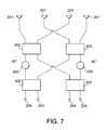
- Fig. 7 shows the structure of a switching scanning type antenna with a butler beamforming matrix.
- This antenna comprises four antenna elements 201, four hybrid circuits 202, and two 45° phase shifters. By switching signals applied to feeder terminals 204 of two hybrid circuits 202, the radiating direction of a beam is changed. This method is available when the number of antenna elements is a power of 2.
- Fig. 8 shows the structure of a phase scanning type antenna.
- the excitation phase of each antenna element 301 is controlled by a phase shifter 304.
- a plurality of beams with different directivity are generated.
- a scanning operation can be performed with high flexibility under the control of the phase shifting unit 304.
- a reflector antenna or an antenna that mechanically changes a beam may be used.
Abstract
Description
Claims (8)
- An adaptive antenna, comprising:a plurality of antenna elements with different directivity;estimating means for estimating states of received signals of said antenna elements for each of delay times that have been designated;selecting means for selecting a part of said antenna elements for each of the delay times corresponding to the estimated result;weighting means for determining the received signals of the part of said antenna elements selected by said selecting means by relevant weights;first combining means for multiplying the received signals to which relevant weights have been determined for each of the delay time and summing the weighted signals;compensating means for compensating the time lag, or time delay of each of the received signals for each of the delay times; andsecond combining means for combining the compensated signals for the delay times.
- The adaptive antenna as set forth in claim 1,
wherein said estimating means estimates the power, intensity, or signal-to-noise ratio of the received desired signals of said antenna elements for each of the delay times. - The adaptive antenna as set forth in claim 2,
wherein said selecting means selects some antenna elements with larger power, intensity, or signal-to-noise ratio of the received desired signal for each of the delay times corresponding to the estimated result. - The adaptive antenna as set forth in claim 2,
wherein said selecting means selects at least one first antenna element and at least one second antenna element corresponding to the estimated result, the first antenna elements having larger power, intensity, or signal-to-noise ratio of the received desired signals for a each of the delay time, the second antenna elements having larger power, intensity, or signal-to-noise ratio of the received undesired delayed signals for each of the delay times. - The adaptive antenna as set forth in claim 2,
wherein said selecting means selects at least one first antenna element and at least one second antenna element corresponding to the estimated result, the first antenna elements having larger power, intensity, or signal-to-noise ratio of the received desired signals for a each of the delay time, the second antenna elements having larger power, intensity, or signal-to-noise ratio of the received interference signals for each of the delay times. - The adaptive antenna as set forth in claim 5,wherein said second selecting means has:means for generating replicas of signals that said antenna elements receive for each of the delay times corresponding to the estimated result and estimating interference signal signals that said antenna elements receive corresponding to the generated replicas and the received signals of said antenna elements; andmeans for selecting the second antenna element corresponding to the estimated result of the interference signal signals.
- An adaptive antenna, comprising:a plurality of antenna elements for generating respective beams with different directivity;estimating means for estimating states of received signals of beams of said antenna elements for each of delay times that have been designated;selecting means for selecting one beam of a part of said antenna elements corresponding to the estimated result;weighting means for determining the received signals of the beams of the part of said antenna elements selected by said selecting means by relevant weights;first combining means for multiplying the received signals to which relevant weights have been determined for each of the delay time and summing the weighted signals;compensating means for compensating the time lag, or time delay of each of the received signals for each of the delay times; andsecond combining means for combining the compensated signals for the delay times.
- The adaptive antenna as set forth in claim 7,
wherein said estimating means estimates the power, intensity, or signal-to-noise ratio of the received signals of beams of said antenna elements for each of the delay times.
Applications Claiming Priority (6)
| Application Number | Priority Date | Filing Date | Title |
|---|---|---|---|
| JP84197 | 1997-01-07 | ||
| JP841/97 | 1997-01-07 | ||
| JP84197 | 1997-01-07 | ||
| JP34689997A JP3526196B2 (en) | 1997-01-07 | 1997-12-16 | Adaptive antenna |
| JP34689997 | 1997-12-16 | ||
| JP346899/97 | 1997-12-16 |
Publications (3)
| Publication Number | Publication Date |
|---|---|
| EP0852407A2 true EP0852407A2 (en) | 1998-07-08 |
| EP0852407A3 EP0852407A3 (en) | 1999-03-17 |
| EP0852407B1 EP0852407B1 (en) | 2003-03-26 |
Family
ID=26333938
Family Applications (1)
| Application Number | Title | Priority Date | Filing Date |
|---|---|---|---|
| EP98300135A Expired - Lifetime EP0852407B1 (en) | 1997-01-07 | 1998-01-07 | Adaptive antenna |
Country Status (4)
| Country | Link |
|---|---|
| US (1) | US6061553A (en) |
| EP (1) | EP0852407B1 (en) |
| JP (1) | JP3526196B2 (en) |
| DE (1) | DE69812445T2 (en) |
Cited By (11)
| Publication number | Priority date | Publication date | Assignee | Title |
|---|---|---|---|---|
| KR20010002673A (en) * | 1999-06-16 | 2001-01-15 | 윤장진 | Diversity by information of base station |
| US6498928B1 (en) | 1999-04-23 | 2002-12-24 | Matsushita Electric Industrial Co., Ltd. | Radio reception apparatus and method for detecting reception timing |
| EP1322049A1 (en) * | 2000-09-08 | 2003-06-25 | Sanyo Electric Co., Ltd. | Radio device |
| US6917790B1 (en) | 1999-10-29 | 2005-07-12 | Amc Centurion Ab | Antenna device and method for transmitting and receiving radio waves |
| US6954180B1 (en) | 1999-10-29 | 2005-10-11 | Amc Centurion Ab | Antenna device for transmitting and/or receiving radio frequency waves and method related thereto |
| US6980782B1 (en) | 1999-10-29 | 2005-12-27 | Amc Centurion Ab | Antenna device and method for transmitting and receiving radio waves |
| US7042394B2 (en) | 2002-08-14 | 2006-05-09 | Skipper Wireless Inc. | Method and system for determining direction of transmission using multi-facet antenna |
| EP1744468A1 (en) * | 2005-07-13 | 2007-01-17 | Skipper Wireless Inc. | Method and system for determining direction of transmission using multi-facet antenna |
| US7610050B2 (en) | 2002-08-14 | 2009-10-27 | Tadaaki Chigusa | System for mobile broadband networking using dynamic quality of service provisioning |
| US7778149B1 (en) | 2006-07-27 | 2010-08-17 | Tadaaki Chigusa | Method and system to providing fast access channel |
| US8160096B1 (en) | 2006-12-06 | 2012-04-17 | Tadaaki Chigusa | Method and system for reserving bandwidth in time-division multiplexed networks |
Families Citing this family (63)
| Publication number | Priority date | Publication date | Assignee | Title |
|---|---|---|---|---|
| SE467436B (en) * | 1990-11-16 | 1992-07-13 | Ericsson Telefon Ab L M | PROCEDURE AND DEVICE TO REDUCE THE NECESSARY SIZE OF A DIGITAL FILTER IN CONNECTION WITH ECO-ELIMINATION IN A SUBSCRIPTION LINE |
| US6275543B1 (en) | 1996-10-11 | 2001-08-14 | Arraycomm, Inc. | Method for reference signal generation in the presence of frequency offsets in a communications station with spatial processing |
| US6463295B1 (en) | 1996-10-11 | 2002-10-08 | Arraycomm, Inc. | Power control with signal quality estimation for smart antenna communication systems |
| US7035661B1 (en) * | 1996-10-11 | 2006-04-25 | Arraycomm, Llc. | Power control with signal quality estimation for smart antenna communication systems |
| DE69926024T2 (en) * | 1998-02-13 | 2005-12-01 | Nec Corp. | Adaptive receiving device with group antenna |
| US6715354B2 (en) | 1998-02-24 | 2004-04-06 | Massachusetts Institute Of Technology | Flaw detection system using acoustic doppler effect |
| JP3940490B2 (en) * | 1998-03-13 | 2007-07-04 | 株式会社東芝 | Distributed antenna system |
| JP3465739B2 (en) * | 1998-04-07 | 2003-11-10 | 日本電気株式会社 | CDMA adaptive antenna receiving apparatus and communication system |
| US6615024B1 (en) | 1998-05-01 | 2003-09-02 | Arraycomm, Inc. | Method and apparatus for determining signatures for calibrating a communication station having an antenna array |
| EP0964530A1 (en) * | 1998-06-05 | 1999-12-15 | Siemens Aktiengesellschaft | Radio communications receiver and interference cancellation method |
| JP3092798B2 (en) * | 1998-06-30 | 2000-09-25 | 日本電気株式会社 | Adaptive transceiver |
| CN1202590C (en) * | 1998-07-13 | 2005-05-18 | Ntt移动通信网株式会社 | Adaptive array antenna |
| DE19916855A1 (en) * | 1999-04-14 | 2000-10-26 | Heinz Lindenmeier | Radio telephone system with group antenna for vehicles |
| JP2000308124A (en) * | 1999-04-26 | 2000-11-02 | Mitsubishi Electric Corp | Control channel arranging method |
| US6600914B2 (en) | 1999-05-24 | 2003-07-29 | Arraycomm, Inc. | System and method for emergency call channel allocation |
| US6141567A (en) * | 1999-06-07 | 2000-10-31 | Arraycomm, Inc. | Apparatus and method for beamforming in a changing-interference environment |
| US7139592B2 (en) * | 1999-06-21 | 2006-11-21 | Arraycomm Llc | Null deepening for an adaptive antenna based communication station |
| US6621808B1 (en) * | 1999-08-13 | 2003-09-16 | International Business Machines Corporation | Adaptive power control based on a rake receiver configuration in wideband CDMA cellular systems (WCDMA) and methods of operation |
| JP3872953B2 (en) * | 1999-12-27 | 2007-01-24 | 株式会社東芝 | Wireless communication device using adaptive antenna |
| JP2001196835A (en) * | 2000-01-17 | 2001-07-19 | Matsushita Electric Ind Co Ltd | Incoming direction estimating method and radio receiver |
| JP2001203620A (en) * | 2000-01-19 | 2001-07-27 | Matsushita Electric Ind Co Ltd | Wireless base station device and wireless communication method |
| US6728515B1 (en) * | 2000-02-16 | 2004-04-27 | Massachusetts Institute Of Technology | Tuned wave phased array |
| US7233627B2 (en) * | 2000-02-23 | 2007-06-19 | Ipr Licensing, Inc. | Method for searching pilot signals to synchronize a CDMA receiver with an associated transmitter |
| JP3379516B2 (en) * | 2000-06-16 | 2003-02-24 | 日本電気株式会社 | Access control device |
| JP4311937B2 (en) * | 2000-09-01 | 2009-08-12 | 三洋電機株式会社 | Radio base system, synchronous window control method, and synchronous window control program |
| US6795409B1 (en) * | 2000-09-29 | 2004-09-21 | Arraycomm, Inc. | Cooperative polling in a wireless data communication system having smart antenna processing |
| US7043259B1 (en) * | 2000-09-29 | 2006-05-09 | Arraycomm, Inc. | Repetitive paging from a wireless data base station having a smart antenna system |
| US6833554B2 (en) * | 2000-11-21 | 2004-12-21 | Massachusetts Institute Of Technology | Laser-induced defect detection system and method |
| US7356351B1 (en) | 2000-12-22 | 2008-04-08 | Durham Logistics, Llc | Method and apparatus for disabling the RF functionality of a multi-function wireless communication device while maintaining local functionality |
| WO2002054627A1 (en) * | 2000-12-27 | 2002-07-11 | Sanyo Electric Co., Ltd. | Radio apparatus, swap detecting method and swap detecting program |
| GB0102316D0 (en) * | 2001-01-30 | 2001-03-14 | Koninkl Philips Electronics Nv | Radio communication system |
| US7061891B1 (en) | 2001-02-02 | 2006-06-13 | Science Applications International Corporation | Method and system for a remote downlink transmitter for increasing the capacity and downlink capability of a multiple access interference limited spread-spectrum wireless network |
| JP3973371B2 (en) * | 2001-03-21 | 2007-09-12 | 三洋電機株式会社 | Radio base system and directivity control method |
| US7209515B2 (en) * | 2001-03-30 | 2007-04-24 | Science Applications International Corporation | Multistage reception of code division multiple access transmissions |
| US6961545B2 (en) * | 2001-04-09 | 2005-11-01 | Atheros Communications, Inc. | Method and system for providing antenna diversity |
| US7221381B2 (en) * | 2001-05-09 | 2007-05-22 | Clairvoyante, Inc | Methods and systems for sub-pixel rendering with gamma adjustment |
| US7006461B2 (en) * | 2001-09-17 | 2006-02-28 | Science Applications International Corporation | Method and system for a channel selective repeater with capacity enhancement in a spread-spectrum wireless network |
| KR20030030590A (en) * | 2001-10-11 | 2003-04-18 | 주식회사 세스텍 | Finger Using Symbol-Rate Weightig in Smart Antenna System, and Its Application for Demodulation Apparatus and Method |
| KR20030031385A (en) * | 2001-10-15 | 2003-04-21 | 주식회사 세스텍 | Finger Using Chip-Rate Weighting in Smart Antenna System, and Its Application for Demodulation Apparatus and Method |
| KR20030033192A (en) * | 2001-10-18 | 2003-05-01 | 주식회사 세스텍 | Finger Using Mixed Weighting in Smart Antenna System, and Its Application for Demodulation Apparatus and Method |
| US7123911B1 (en) * | 2002-08-08 | 2006-10-17 | Sprint Spectrum L.P. | Method and system of wireless signal repeating |
| JP3905541B2 (en) * | 2002-11-28 | 2007-04-18 | 富士通株式会社 | Delay profile estimation apparatus and correlator |
| US20040233308A1 (en) * | 2003-05-20 | 2004-11-25 | Elliott Candice Hellen Brown | Image capture device and camera |
| KR100522604B1 (en) * | 2003-05-27 | 2005-10-20 | 삼성전자주식회사 | Method and apparatus for managing channel on broadcasting system having multiple frequency network |
| JP2005295312A (en) * | 2004-04-01 | 2005-10-20 | Hitachi Ltd | Portable radio equipment |
| US20060203794A1 (en) * | 2005-03-10 | 2006-09-14 | Qualcomm Incorporated | Systems and methods for beamforming in multi-input multi-output communication systems |
| JP4518999B2 (en) * | 2005-05-17 | 2010-08-04 | 日本放送協会 | MIMO receiving antenna selection device |
| US9435893B2 (en) | 2007-05-21 | 2016-09-06 | Spatial Digital Systems, Inc. | Digital beam-forming apparatus and technique for a multi-beam global positioning system (GPS) receiver |
| US10490892B2 (en) | 2007-12-06 | 2019-11-26 | Spatial Digital Systems, Inc. | Satellite ground terminal incorporating a smart antenna that rejects interference |
| JP2009159273A (en) * | 2007-12-26 | 2009-07-16 | Toshiba Corp | Radio communication apparatus, control method of radio communication apparatus, and control program of the same |
| JP2009246517A (en) * | 2008-03-28 | 2009-10-22 | Kyocera Corp | Base station apparatus and channel allocation method |
| EP2112775B1 (en) * | 2008-04-25 | 2018-06-06 | Telefonaktiebolaget LM Ericsson (publ) | Method and apparatus for compensation for propagation delay in a wireless communication system |
| US8289083B2 (en) | 2009-04-13 | 2012-10-16 | Viasat, Inc. | Active power splitter |
| US8693970B2 (en) | 2009-04-13 | 2014-04-08 | Viasat, Inc. | Multi-beam active phased array architecture with independant polarization control |
| TWI536661B (en) * | 2009-04-13 | 2016-06-01 | 凡爾賽特公司 | System for communication and method for communicating rf signals |
| US10516219B2 (en) | 2009-04-13 | 2019-12-24 | Viasat, Inc. | Multi-beam active phased array architecture with independent polarization control |
| US8817672B2 (en) | 2009-04-13 | 2014-08-26 | Viasat, Inc. | Half-duplex phased array antenna system |
| US8699626B2 (en) | 2011-11-29 | 2014-04-15 | Viasat, Inc. | General purpose hybrid |
| US8737531B2 (en) | 2011-11-29 | 2014-05-27 | Viasat, Inc. | Vector generator using octant symmetry |
| FI125462B (en) * | 2013-01-29 | 2015-10-15 | Inverpolis Oy | Procedures and systems for using a phased antenna array |
| JP6920058B2 (en) * | 2016-12-26 | 2021-08-18 | 株式会社日立国際電気 | Wireless communication system and beam control method |
| RU2744030C1 (en) * | 2020-09-02 | 2021-03-02 | Акционерное общество научно-внедренческое предприятие "ПРОТЕК" | Combined adaptive antenna array |
| RU2747377C1 (en) * | 2020-10-15 | 2021-05-04 | Акционерное общество научно-внедренческое предприятие "ПРОТЕК" | Method for compensating interference signals in combined adapted antenna array |
Citations (4)
| Publication number | Priority date | Publication date | Assignee | Title |
|---|---|---|---|---|
| US4736460A (en) * | 1986-11-10 | 1988-04-05 | Kenneth Rilling | Multipath reduction system |
| EP0570166A1 (en) * | 1992-05-12 | 1993-11-18 | Hughes Aircraft Company | Interference detection and cancellation system and method |
| EP0582233A1 (en) * | 1992-07-31 | 1994-02-09 | Nec Corporation | Adaptive receiver for multipath fading channels |
| EP0670608A2 (en) * | 1994-03-03 | 1995-09-06 | Atr Optical And Radio Communications Research Laboratories | Apparatus and method for adaptively controlling array antenna comprising adaptive control means with improved initial value setting arrangement |
-
1997
- 1997-12-16 JP JP34689997A patent/JP3526196B2/en not_active Expired - Fee Related
-
1998
- 1998-01-02 US US09/002,394 patent/US6061553A/en not_active Expired - Fee Related
- 1998-01-07 DE DE69812445T patent/DE69812445T2/en not_active Expired - Lifetime
- 1998-01-07 EP EP98300135A patent/EP0852407B1/en not_active Expired - Lifetime
Patent Citations (4)
| Publication number | Priority date | Publication date | Assignee | Title |
|---|---|---|---|---|
| US4736460A (en) * | 1986-11-10 | 1988-04-05 | Kenneth Rilling | Multipath reduction system |
| EP0570166A1 (en) * | 1992-05-12 | 1993-11-18 | Hughes Aircraft Company | Interference detection and cancellation system and method |
| EP0582233A1 (en) * | 1992-07-31 | 1994-02-09 | Nec Corporation | Adaptive receiver for multipath fading channels |
| EP0670608A2 (en) * | 1994-03-03 | 1995-09-06 | Atr Optical And Radio Communications Research Laboratories | Apparatus and method for adaptively controlling array antenna comprising adaptive control means with improved initial value setting arrangement |
Non-Patent Citations (1)
| Title |
|---|
| WANG H ET AL: "ADAPTIVE ARRAY ANTENNA COMBINED WITH TAPPED DELAY LINE USING PROCESSING GAIN FOR DIRECT-SEQUENCE/SPREAD-SPECTRUM MULTIPLE -ACCESSSYSTEM" ELECTRONICS & COMMUNICATIONS IN JAPAN, PART I - COMMUNICATIONS, vol. 76, no. 5, 1 May 1993, pages 101-113, XP000425186 * |
Cited By (12)
| Publication number | Priority date | Publication date | Assignee | Title |
|---|---|---|---|---|
| US6498928B1 (en) | 1999-04-23 | 2002-12-24 | Matsushita Electric Industrial Co., Ltd. | Radio reception apparatus and method for detecting reception timing |
| KR20010002673A (en) * | 1999-06-16 | 2001-01-15 | 윤장진 | Diversity by information of base station |
| US6917790B1 (en) | 1999-10-29 | 2005-07-12 | Amc Centurion Ab | Antenna device and method for transmitting and receiving radio waves |
| US6954180B1 (en) | 1999-10-29 | 2005-10-11 | Amc Centurion Ab | Antenna device for transmitting and/or receiving radio frequency waves and method related thereto |
| US6980782B1 (en) | 1999-10-29 | 2005-12-27 | Amc Centurion Ab | Antenna device and method for transmitting and receiving radio waves |
| EP1322049A1 (en) * | 2000-09-08 | 2003-06-25 | Sanyo Electric Co., Ltd. | Radio device |
| EP1322049A4 (en) * | 2000-09-08 | 2009-12-16 | Sanyo Electric Co | Radio device |
| US7042394B2 (en) | 2002-08-14 | 2006-05-09 | Skipper Wireless Inc. | Method and system for determining direction of transmission using multi-facet antenna |
| US7610050B2 (en) | 2002-08-14 | 2009-10-27 | Tadaaki Chigusa | System for mobile broadband networking using dynamic quality of service provisioning |
| EP1744468A1 (en) * | 2005-07-13 | 2007-01-17 | Skipper Wireless Inc. | Method and system for determining direction of transmission using multi-facet antenna |
| US7778149B1 (en) | 2006-07-27 | 2010-08-17 | Tadaaki Chigusa | Method and system to providing fast access channel |
| US8160096B1 (en) | 2006-12-06 | 2012-04-17 | Tadaaki Chigusa | Method and system for reserving bandwidth in time-division multiplexed networks |
Also Published As
| Publication number | Publication date |
|---|---|
| US6061553A (en) | 2000-05-09 |
| JPH10256821A (en) | 1998-09-25 |
| DE69812445T2 (en) | 2004-04-08 |
| DE69812445D1 (en) | 2003-04-30 |
| JP3526196B2 (en) | 2004-05-10 |
| EP0852407A3 (en) | 1999-03-17 |
| EP0852407B1 (en) | 2003-03-26 |
Similar Documents
| Publication | Publication Date | Title |
|---|---|---|
| EP0852407B1 (en) | Adaptive antenna | |
| US7043275B2 (en) | Radio communication apparatus using adaptive antenna | |
| US7092690B2 (en) | Genetic algorithm-based adaptive antenna array processing method and system | |
| EP1685661B1 (en) | Method and apparatus for multi-beam antenna system | |
| US7312750B2 (en) | Adaptive beam-forming system using hierarchical weight banks for antenna array in wireless communication system | |
| EP1043801B1 (en) | Adaptive array antenna system | |
| US6847327B2 (en) | Base station, base station module and method for direction of arrival estimation | |
| EP1202389A1 (en) | Transmission antenna directivity control apparatus and method | |
| US20050282587A1 (en) | Base station apparatus with reception and diversity weight combining | |
| WO2002007258A2 (en) | Adaptive antenna for use in same frequency networks | |
| US8520784B1 (en) | Coherent beam combining of independently faded signals | |
| US7006849B2 (en) | Spatial domain matched filtering method and array receiver in wireless communication system | |
| WO2016141954A1 (en) | A method, control system and communication system for adapting beam patterns | |
| US7414578B1 (en) | Method for efficiently computing the beamforming weights for a large antenna array | |
| US7221698B2 (en) | Adaptive array antenna receiving apparatus | |
| US7069052B2 (en) | Data transmission method in base station of radio system, base station of radio system, and antenna array of base station | |
| US6980832B1 (en) | Method of reducing transmission power in a wireless communication system | |
| EP1146665A1 (en) | Base station device and radio receiving method | |
| Celik et al. | Genetic-algorithm-based antenna array design for a 60-GHz hybrid smart antenna system | |
| JP3832083B2 (en) | Base station antenna device | |
| JP4198570B2 (en) | Adaptive antenna transmission apparatus and adaptive antenna transmission method | |
| Kantl et al. | Analysis and Performance of Smart Antenna System for Wireless Communication |
Legal Events
| Date | Code | Title | Description |
|---|---|---|---|
| PUAI | Public reference made under article 153(3) epc to a published international application that has entered the european phase |
Free format text: ORIGINAL CODE: 0009012 |
|
| 17P | Request for examination filed |
Effective date: 19980129 |
|
| AK | Designated contracting states |
Kind code of ref document: A2 Designated state(s): DE FR GB |
|
| AX | Request for extension of the european patent |
Free format text: AL;LT;LV;MK;RO;SI |
|
| PUAL | Search report despatched |
Free format text: ORIGINAL CODE: 0009013 |
|
| AK | Designated contracting states |
Kind code of ref document: A3 Designated state(s): AT BE CH DE DK ES FI FR GB GR IE IT LI LU MC NL PT SE |
|
| AX | Request for extension of the european patent |
Free format text: AL;LT;LV;MK;RO;SI |
|
| AKX | Designation fees paid |
Free format text: DE FR GB |
|
| GRAG | Despatch of communication of intention to grant |
Free format text: ORIGINAL CODE: EPIDOS AGRA |
|
| 17Q | First examination report despatched |
Effective date: 20020328 |
|
| GRAG | Despatch of communication of intention to grant |
Free format text: ORIGINAL CODE: EPIDOS AGRA |
|
| GRAG | Despatch of communication of intention to grant |
Free format text: ORIGINAL CODE: EPIDOS AGRA |
|
| GRAH | Despatch of communication of intention to grant a patent |
Free format text: ORIGINAL CODE: EPIDOS IGRA |
|
| GRAH | Despatch of communication of intention to grant a patent |
Free format text: ORIGINAL CODE: EPIDOS IGRA |
|
| GRAA | (expected) grant |
Free format text: ORIGINAL CODE: 0009210 |
|
| AK | Designated contracting states |
Designated state(s): DE FR GB |
|
| REG | Reference to a national code |
Ref country code: GB Ref legal event code: FG4D |
|
| REF | Corresponds to: |
Ref document number: 69812445 Country of ref document: DE Date of ref document: 20030430 Kind code of ref document: P |
|
| ET | Fr: translation filed | ||
| PLBE | No opposition filed within time limit |
Free format text: ORIGINAL CODE: 0009261 |
|
| STAA | Information on the status of an ep patent application or granted ep patent |
Free format text: STATUS: NO OPPOSITION FILED WITHIN TIME LIMIT |
|
| 26N | No opposition filed |
Effective date: 20031230 |
|
| REG | Reference to a national code |
Ref country code: GB Ref legal event code: 746 Effective date: 20070317 |
|
| PGFP | Annual fee paid to national office [announced via postgrant information from national office to epo] |
Ref country code: DE Payment date: 20110105 Year of fee payment: 14 Ref country code: FR Payment date: 20110128 Year of fee payment: 14 |
|
| PGFP | Annual fee paid to national office [announced via postgrant information from national office to epo] |
Ref country code: GB Payment date: 20110105 Year of fee payment: 14 |
|
| GBPC | Gb: european patent ceased through non-payment of renewal fee |
Effective date: 20120107 |
|
| REG | Reference to a national code |
Ref country code: FR Ref legal event code: ST Effective date: 20120928 |
|
| PG25 | Lapsed in a contracting state [announced via postgrant information from national office to epo] |
Ref country code: DE Free format text: LAPSE BECAUSE OF NON-PAYMENT OF DUE FEES Effective date: 20120801 Ref country code: GB Free format text: LAPSE BECAUSE OF NON-PAYMENT OF DUE FEES Effective date: 20120107 |
|
| REG | Reference to a national code |
Ref country code: DE Ref legal event code: R119 Ref document number: 69812445 Country of ref document: DE Effective date: 20120801 |
|
| PG25 | Lapsed in a contracting state [announced via postgrant information from national office to epo] |
Ref country code: FR Free format text: LAPSE BECAUSE OF NON-PAYMENT OF DUE FEES Effective date: 20120131 |