EP1161802B1 - Adaptive power control in a radio communication system - Google Patents
Adaptive power control in a radio communication system Download PDFInfo
- Publication number
- EP1161802B1 EP1161802B1 EP00917548A EP00917548A EP1161802B1 EP 1161802 B1 EP1161802 B1 EP 1161802B1 EP 00917548 A EP00917548 A EP 00917548A EP 00917548 A EP00917548 A EP 00917548A EP 1161802 B1 EP1161802 B1 EP 1161802B1
- Authority
- EP
- European Patent Office
- Prior art keywords
- base station
- mobile station
- cell
- mobile
- interference
- Prior art date
- Legal status (The legal status is an assumption and is not a legal conclusion. Google has not performed a legal analysis and makes no representation as to the accuracy of the status listed.)
- Expired - Lifetime
Links
Images

Classifications
-
- H—ELECTRICITY
- H04—ELECTRIC COMMUNICATION TECHNIQUE
- H04W—WIRELESS COMMUNICATION NETWORKS
- H04W52/00—Power management, e.g. TPC [Transmission Power Control], power saving or power classes
- H04W52/04—TPC
- H04W52/18—TPC being performed according to specific parameters
- H04W52/24—TPC being performed according to specific parameters using SIR [Signal to Interference Ratio] or other wireless path parameters
- H04W52/243—TPC being performed according to specific parameters using SIR [Signal to Interference Ratio] or other wireless path parameters taking into account interferences
-
- H—ELECTRICITY
- H04—ELECTRIC COMMUNICATION TECHNIQUE
- H04W—WIRELESS COMMUNICATION NETWORKS
- H04W52/00—Power management, e.g. TPC [Transmission Power Control], power saving or power classes
- H04W52/04—TPC
- H04W52/18—TPC being performed according to specific parameters
- H04W52/24—TPC being performed according to specific parameters using SIR [Signal to Interference Ratio] or other wireless path parameters
- H04W52/242—TPC being performed according to specific parameters using SIR [Signal to Interference Ratio] or other wireless path parameters taking into account path loss
-
- H—ELECTRICITY
- H04—ELECTRIC COMMUNICATION TECHNIQUE
- H04W—WIRELESS COMMUNICATION NETWORKS
- H04W52/00—Power management, e.g. TPC [Transmission Power Control], power saving or power classes
- H04W52/04—TPC
- H04W52/18—TPC being performed according to specific parameters
- H04W52/28—TPC being performed according to specific parameters using user profile, e.g. mobile speed, priority or network state, e.g. standby, idle or non transmission
-
- H—ELECTRICITY
- H04—ELECTRIC COMMUNICATION TECHNIQUE
- H04W—WIRELESS COMMUNICATION NETWORKS
- H04W52/00—Power management, e.g. TPC [Transmission Power Control], power saving or power classes
- H04W52/04—TPC
- H04W52/30—TPC using constraints in the total amount of available transmission power
- H04W52/36—TPC using constraints in the total amount of available transmission power with a discrete range or set of values, e.g. step size, ramping or offsets
-
- H—ELECTRICITY
- H04—ELECTRIC COMMUNICATION TECHNIQUE
- H04W—WIRELESS COMMUNICATION NETWORKS
- H04W52/00—Power management, e.g. TPC [Transmission Power Control], power saving or power classes
- H04W52/04—TPC
- H04W52/18—TPC being performed according to specific parameters
- H04W52/24—TPC being performed according to specific parameters using SIR [Signal to Interference Ratio] or other wireless path parameters
-
- H—ELECTRICITY
- H04—ELECTRIC COMMUNICATION TECHNIQUE
- H04W—WIRELESS COMMUNICATION NETWORKS
- H04W52/00—Power management, e.g. TPC [Transmission Power Control], power saving or power classes
- H04W52/04—TPC
- H04W52/30—TPC using constraints in the total amount of available transmission power
- H04W52/34—TPC management, i.e. sharing limited amount of power among users or channels or data types, e.g. cell loading
Definitions
- the present invention relates to power control in radio communications, and more particularly, to more efficient and effective open loop power control.
- the adaptive open loop power control approach of the present invention is particularly well-suited for communications in a Code Division Multiple Access (CDMA) cellular radio system.
- CDMA Code Division Multiple Access
- WCDMA Wideband Code Division Multiple Access
- a mobile station Before transmitting over an "uplink” channel, a mobile station must set its transmission power level. Similarly, the radio access network must set base station transmit power on "downlink channels," e.g., a paging channel (PCH), a forward access channel (FACH), in addition to traffic channels (TCH).
- PCH paging channel
- FACH forward access channel
- TCH traffic channels
- the physical characteristics of a radio channel may vary significantly due to a number of reasons. For example, the signal propagation loss between a radio transmitter and receiver varies as a function of their respective locations, obstacles, weather, etc. As a result, large differences may arise in the strength of signals received at the base station from different mobiles. If the transmission power of a mobile station signal is too low, the receiving base station may not correctly decode a weak signal, and the signal will have to be corrected (if possible) or retransmitted. Accordingly, erroneous receipt of the signals adds to the delay associated with radio access procedures, increases data processing overhead, and reduces the available radio bandwidth because signals must be retransmitted. On the other hand, if the mobile transmission power is too high, the signals transmitted by the mobile station create interference for the other mobile and base stations in the system.
- Interference is a particularly severe problem in CDMA systems where a large number of radios transmit and receive on the same frequency. If one mobile station transmits at a power output that is too large, the interference it creates degrades the signal-to-interference ratio (SIR) of signals received from other mobile radios to the point that a receiving base station cannot correctly demodulate transmissions from the other mobile radios. In fact, if a mobile station transmits a signal at twice the power level needed for the signal to be accurately received at the base station receiver, that mobile signal occupies roughly twice the system capacity as it would if the signal were transmit at the optimum power level. Unregulated, it is not uncommon for a strong mobile station to transmit signals that are received at the base station at many, many times the strength of other mobile transmissions. The loss of system capacity to such excessively "strong" mobile stations is unacceptable.
- SIR signal-to-interference ratio
- open loop power control the transmit power is calculated at the transmitter based on one or more parameters, and the calculated value is used to set the transmit power level.
- the transmit power is adjusted in order to match an estimated path loss so that the signal is received at the base station at a predetermined power level.
- Closed loop power control relies on feedback from the receiver so that the transmitter knows, for example, at what power level (and sometimes also at what interference level) the transmitted signal was received. Using this feedback, the transmitter then appropriately adjusts its transmit power level. Alternatively, the receiver may simply order the transmitter to increase or decrease its transmit power.
- the additionally received feedback information means that closed loop power control is generally more accurate than open loop power control.
- Common channels for both uplink and downlink shared by several mobile radios are typically used to transmit relatively short control signaling messages which do not justify the additional "cost” in terms of delay, signaling overhead, spreading code allocation, and bandwidth consumption associated with dedicated channels.
- Common channels may also be utilized to transmit short traffic data packets appended directly to the typical control messages sent on common channels. "Lower cost" open loop power control is well-suited for transmission over common channels being faster, less complicated, and occupying fewer radio resources than closed loop power control commonly used for dedicated channels.
- One type of common channel shared by mobile stations is a random access channel which provides communication between plural mobile stations and a base station when those mobile stations have not been allocated a dedicated channel.
- Access channel messages may include for example call reservations, responses to pages, orders, registrations, and small size user data packets.
- each additional mobile station transmitting on that access channel contributes to the background noise and interference thereby diminishing the system's finite capacity. Consequently, it is important to set the appropriate output power of the mobile station before transmitting.
- the mobile station calculates an open loop transmission power P tx to be used on the random access channel in the uplink direction so that the mobile's signal is received at the base station at a predetermined power level.
- the mobile station strives to achieve a target Carrier-to-Interference Ratio (CIR) ⁇ t at the base station.
- CIR Carrier-to-Interference Ratio
- the carrier-to-interference ratio actually received at the base station corresponds to the received uplink carrier power C UL minus the uplink interference I UL .
- the received carrier power C UL corresponds to the mobile's transmit power level P tx minus the path loss L.
- the open loop power control therefore can determine the transmit power P ⁇ tx as a function of the target carrier-to-interference ratio ⁇ t , an uplink interference estimate Î UL , and a path loss estimate L ⁇ .
- the path loss estimate L ⁇ may be obtained with the mobile station measuring the received power of a known signal (e.g., a downlink pilot or other broadcasted signals) transmitted on a downlink channel by the base station.
- the known signal includes a message that informs the mobile of the power at which that known signal is being transmit by the base station.
- the uplink interference is estimated (measured) and broadcast by the base station over the cell together with a downlink pilot signal output power value.
- the open loop power control algorithm in equation (1) suffers from uncertainties that make the received carrier-to-interference ratio different (often significantly different) from the target carrier-to-interference ratio ⁇ t .
- the estimated path loss L ⁇ typically differs from the actual path loss L because of a number of factors such as: (1) the actual power at which the base station transmits the pilot signal likely differs from the broadcasted downlink pilot signal output power value, (2) inaccurate measurements of signal strength in the mobile station, and (3) fading, noise, and delays in measuring the path loss.
- the uplink interference I UL can change significantly since it was last measured by the base station.
- the transmit power P ⁇ tx determined by the open loop power control procedure is a reasonably accurate estimate, the actual transmit power P tx at which the mobile station transmits likely differs from the commanded transmission power due to imperfections and hardware limitations in the mobile station implementation.
- the mobile transmit power varies significantly depending on the current temperature of the mobile station and on the nonlinearity of components employed in the mobile station.
- the actual transmit power P tx , the actual uplink interference, and the actual path loss cannot be known with certainty.
- the shortcomings of open loop power control described for uplink transmission also apply to open loop power control for downlink transmission on common channels, e.g. the forward access channel (FACH), etc.
- FACH forward access channel
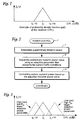
- Fig. 1 illustrates this uncertainty through a sketch of the probability density function (PDF) f r ( ⁇ ) of the received CIR.
- PDF probability density function
- Fig. 1 simply illustrates the fact that there is a spread of the received CIR.
- One way to address some of the above-described problems is to employ power "ramping" such as described in Ericsson's U.S. Patent No. 5,430,760 to Dent.
- the mobile station initiates a random access at a low initial transmit power level and gradually (e.g., incrementally) increases the transmission power level until the base station detects and acknowledges the access signal. Once detected, power level of the message is maintained at the detected level.
- power ramp-up approach is that it could introduce significant delay into the access procedure. Specifically, there may be substantial delay between access attempts while the mobile waits for an acknowledgement of the most recently transmitted access signal. This delay is particularly undesirable at low traffic load levels when interference caused by a random access transmission is of less importance.
- power ramping on preamble level may be employed as described in commonly-assigned U.S. Patent Application Serial No. 09/166,679, filed October 5, 1998 , and incorporated herein by reference.
- the mobile station transmits only short preamble signals with increasing power until the base station detects the received preamble energy (as opposed to decoding the entire random access message) and sends back a positive acquisition indicator to the mobile.
- the initial transmit power level from which to start ramping must be decided by the transmitter based on the above described open loop power control.
- CDMA Reverse Link Open Loop Power Control (S. Soliman et al.), Communications for Global Users, Orlando, Dec. 6-9, 1992 , Proceedings of the Global Telecommunications Conference (Globecom), New York, IEEE, US relates to power control in a CDMA mobile telephone system employing power control on both forward and reverse links to solve near-end far-end problems, corner problems, and long and short term channel variations.
- the document presents an open-loop power control algorithm for minimizing the mobile transmitted power and hence reducing the level of interference.
- the adaptive power control of the present invention overcomes the above-identified problems and satisfies these and other objects.
- delay on a common radio communications channel employed by plural mobile stations to communicate with a base station located in a corresponding geographical cell area is minimized by adapting transmission power based on a traffic load. For lower traffic loads, a higher transmission power is permitted. For higher traffic loads, a lower power level is set.
- Transmit power level is determined using a desired signal ratio, such as a target CIR, a transmission path loss over the radio communications channel, and an interference value.
- An adaptive power parameter is also introduced which adapts the transmit power control based on one or more other current communications conditions and/or characteristics of the mobile station.
- the adaptive power parameter may be a function of a current interference in a base station cell either alone or in combination with a current interference in one or more neighboring cells.
- the adaptive power parameter may also account for a type of data packet connection to be employed between the mobile station and the base station after random access, a mobile station's subscription, a current temperature of the mobile station, a current base station used by the mobile station, a current estimated path loss between the mobile station and base station, and/or other factors.
- the present invention may be applied advantageously to mobile transmissions on an uplink, random access channel in a CDMA communications system, the present invention can also advantageously be employed to control the transmit power of a radio in any direction, over any particular channel type, and in any type of communications system, e.g., FDMA, TDMA, etc.
- the present invention is sometimes described in the context of a random access type of common channel, the invention is equally applicable to other common channels and to dedicated channels. Indeed, the present invention can be employed in any transmit power control situation. In other instances, detailed descriptions of well-known methods, interfaces, devices, and signaling techniques are omitted so as not to obscure the description of the present invention with unnecessary details.
- a transmitting radio determines a preliminary transmit power (block 4).
- setting the radio transmit power level based upon this determined preliminary transmit power will very likely result in the receiving radio receiving the signal at an undesired carrier-to-interference ratio, i.e., either too high or too low of a CIR.
- the preliminary transmit power in block 4 is adjusted using an adaptive parameter that accounts for one or more current traffic conditions (block 6).
- the adaptive parameter accounts for a current traffic load affecting this radio communication.
- the radio's transmit power is then controlled based upon the adjusted transmit power value (block 8).
- the adaptive parameter value is set higher resulting in a higher transmit power value.
- the adaptive power parameter value is set lower, perhaps even to a negative value to minimize the disturbance to other nearby radios. Otherwise, an excessive transmit power could, in some cases, result in an uncontrolled increase of other radio transmit powers (i.e., the party effect) until they reach their maximum transmit power.
- Fig. 3 shows a graph of the probability density function f ⁇ ( ⁇ ) of received carrier-to-interference ratio ⁇ relative to the target CIR ⁇ , and the effects of different adaptive parameter values.
- a larger adaptive power parameter value shifts the f ⁇ ( ⁇ ) graph to the right meaning that there is a higher probability of a received CIR larger than the target CIR. This results in a greater likelihood of a successful communication and a lower delay associated with that communication.
- a lower adaptive power parameter value shifts the graph to the left to decrease the amount of interference caused by each user with, however, a lower probability of a successful transmission.
- the present invention also provides the mobile station with an ability to vary the adaptive power parameter due to temperature, mobile station systematic errors, and base station systematic errors so that the width of the probability density function f r ( ⁇ ) decreases.
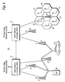
- Fig. 4 illustrates a mobile radio cellular communications system 10 which may be a CDMA or a wideband CDMA communications system.
- Radio network controllers (RNCs) 12 and 14 control various radio network functions including for example radio access bearer setup, diversity handover, etc.
- Radio network controller 12 is coupled to a plurality of base stations 16, 18, and 20.
- Radio network controller 14 is connected to base stations 22, 24, and 26.
- Each base station serves a geographical area referred to as a cell, and a cell may be divided into plural sectors.
- Base station 26 is shown as having six antenna sectors S1-S6.
- the base stations are connected to their corresponding radio network controller by various means such as dedicated telephone lines, optical fiber links, microwave links, etc.
- Both radio network controllers 12 and 14 are connected with external networks such as the Public Switched Telephone Network (PSTN), the Internet, etc. through one or more mobile switching centers and/or a packet radio service node (not shown).
- PSTN Public Switched Telephone Network
- the RNC directs mobile station calls via the appropriate base station(s).
- Fig. 4 two mobile stations 28 and 30 are shown communicating with plural base stations.
- Mobile station 28 communicates with base stations 16, 18, and 20, and mobile station 30 communicates with base stations 20 and 22.
- a control link between radio network controllers 12 and 14 permits diversity communications to/from mobile station 30 via base stations 20 and 22.
- Each radio communication channel established between the mobile station and a base station has an uplink component and a downlink component. Since multiple communications utilize the same radio frequencies in CDMA communication, spreading codes along with other well-known CDMA techniques are used to distinguish between the various mobile station and base station communications.
- the term "channel" refers to a CDMA channel which, for any mobile station, is defined in terms of an RF frequency and a particular code sequence.
- Each radio network controller includes a network interface 52 for interfacing communications with various base stations.
- the network interface 52 is connected to a controller 50 and to a diversity handover unit (DHO) 54.
- Diversity handover unit 54 performs numerous functions required for establishing, maintaining, and dropping diversity connections such as diversity combining, diversity splitting, power control and other link related radio resource control algorithms.
- Each base station includes a corresponding network interface 60 for interfacing with the RNC.
- the base station includes a controller 62 connected to a plurality of transceivers (TRX) 64, 66, 68, and 70, as well as a transmit power controller 72.
- Controller 62 controls the overall operation of the base station as well as the establishment, maintenance, and release of radio connections.
- Representative transceivers 64-70 are individually assigned to specific communications with mobile stations. At least one transceiver is employed as a common control channel over which the base station transmits common signaling such as pilot, synchronization, or other broadcast signaling. Mobile stations within or near that base station's cell monitor the common control channel.
- a common channel called the random access channel (RACH) is used by the mobile to transmit (uplink) stations to request a dedicated channel and may also be used for limited amounts of user data.
- a common forward access channel (FACH) is used by the base station to transmit (downlink) limited amounts of user data.
- RACH random access channel
- FACH forward access channel
- Transmit power controller 72 performs open loop power control for the downlink, and the transmit power controller performs closed loop power control procedures for the uplink to control the transmit powers from all mobile transmissions received by the base station, e.g., so they are at approximately the same power level assuming all mobiles are using the same type of service.
- Fig. 6 illustrates additional details of a mobile station shown in Fig. 4 .
- the mobile station includes a controller 80 connected to a RAKE receiver 82, a transmit power controller 88, and a transmitter 90.
- the RAKE receiver 82 includes plural receivers 84 and 85 (there may be additional receivers as well) connected to a diversity combiner 86.
- One or more signal strength detectors (not shown) or similar detector(s) are employed in the mobile receiver 82 to detect the signal strength or other parameter of received signals.
- the transmissions from base stations are received as multipaths in the receivers 84 and 85, combining diversity combiner 86 and processed as one signal.
- Transmit power controller 88 determines the power level (preferably as a carrier-to-interference ratio (CIR) or as a signal-to-interference ration ( E b / I o )) of the received, diversity-combined signal.
- CIR carrier-to-interference ratio
- E b / I o signal-to
- the mobile station 30 detects a target carrier-to-interference ratio ⁇ t broadcast from a base station over a downlink access channel.
- the target CIR ⁇ t may also be predefined in the system, and hence, already known by the mobile station.
- the mobile station 30 also detects the current uplink interference estimate Î UL measured and broadcast by the base station over its corresponding geographic cell together with a downlink pilot (or other broadcast) signal transmit power value.
- This power offset ⁇ preferably is a cell specific offset ⁇ C that depends on the current traffic load in the cell.
- ⁇ C may be a function of the measured uplink interference Î UL in the cell where the mobile station performs a random access, as well as the uplink interference in one or more neighboring cells.
- the uplink interference Î UL is measured in the cell where the mobile station performs the random access, and Î UL 1 , Î UL 2 ..., Î ULN are measured uplink interference values in N surrounding cells. Therefore, while only the local uplink interference value Î UL may be employed, several uplink interference values from the surrounding cells are preferably used. This is because in a CDMA system all mobile stations transmit and receive on the same frequency and therefore create uplink interference in surrounding cells as well. As a result, the interference levels in these cells typically affect the overall impact of uplink interference on the mobile.
- ⁇ C A(I ULmax - Î UL . ), where A is a constant and I ULmax is the maximum allowed uplink interference.
- A the interference value(s)
- ⁇ C the larger ⁇ C may be.
- the interference in the mobile's current cell should also have a larger effect on ⁇ C than the interference values for neighboring cells.
- a random access always creates more uplink interference.
- the other, already-active mobiles therefore need to increase their respective transmit powers to maintain the same target CIR thereby increasing the uplink interference even more.
- the system can allow this to occur because the I UL will not increase above a maximum allowed value which defines the maximum uplink capacity of the CDMA system.
- the interference created by the random access may be compensated for in other active mobiles in the cell using closed loop power control.
- the parameter ⁇ C is set higher resulting in a higher transmission power. As illustrated above in Fig. 3 , this moves the probability density function of the carrier-to-interference ratio to the right of the target CIR resulting in a larger probability of successful random access and a lower packet delay. Low traffic load cases will predictably be quite common since the cellular system will probably be dimensioned for higher traffic load cases which typically occur only during certain busy times. So this higher transmission power will result in improved system performance for the typical traffic scenario. Conversely, at higher traffic loads, when the uplink interference is close to a maximum allowed value, the power offset ⁇ C is set lower, perhaps even to a negative value as illustrated in Fig. 3 to avoid excessive disturbance for other users on the uplink.
- the power offset ⁇ C in accordance with one example of the present invention may be applied in the setting of mobile transmit power for an uplink common channel, (e.g., a RACH channel).
- the power offset ⁇ C may be applied for downlink common channels with open loop power control, (e.g., a FACH channel).
- the path loss and the interference at the mobile station is measured and reported by the mobile to the radio network.
- the mobile station informs the network of how much more or less the base station transmit power level on FACH should be compared to the broadcast pilot signal transmit power level.
- the radio network may then apply the power offset ⁇ C to that transmit power level and adapt it to high or low traffic load conditions as described above for uplink transmissions.
- the mobile's transmit power at random access may also depend on user specific parameters either alone or in addition to uplink interference.
- the power offset may depend on the particular data packet mode to be employed by the mobile station after the random access. For example, if the mobile station will be allocated a dedicated traffic channel immediately after the random access, the power offset may be set to a higher value to provide a quick random access and thereby facilitate a rapid transfer to a dedicated channel.
- Dedicated traffic channels have higher capacity and generally employ more precise closed loop power control which creates less interference to the system overall compared to shared or common traffic channels that typically do not employ closed loop power control.
- the power offset may depend on a mobile user's subscription.
- the power offset ⁇ U may also be used without ⁇ C and in setting of the transmit power level on a downlink common channel, e.g., the FACH channel.
- the mobile's transmit power at random access may depend still on other factors. As described in the background, part of the error between the received carrier-to-interference ratio (CIR) and the target CIR ( ⁇ t ) is due to the inability of the mobile station to actually transmit at the calculated transmit power P ⁇ IX . Instead, the mobile may transmit at an actual power P IX that may differ considerably from the calculated or otherwise desired power P ⁇ tx .
- the following example variables may have a significant impact on the actual transmission power level despite the transmit power controller 88 providing a desired transmit power level to the transmitter 90:
- Such mobile and base station specific errors may be compensated in the present invention using an equipment-specific power offset ⁇ E .
- Knowledge of the mobile station specific parameters may be accumulated and stored in the mobile station.
- Knowledge of base station specific errors may be accumulated and stored for each base station in the mobile station. The mobile station then applies the appropriate compensation.
- the base station measures the received power level accurately and that the broadcast power level for the base station pilot signal is equal to the actual transmitted power level of the pilot.
- the example illustrates the mobile station compensating for temperature drift, systematic errors in signal strength detection, and systematic differences between the actual transmitted output power and the assigned output power. Other factors that result in transmit power errors may be compensated for in a similar way.
- the mobile station measures and stores its current temperature, the current transmit power level, and the signal power error E in a look-up table for this particular temperature and power level.
- E(t - 1 ) denotes a previously received signal power error value for this temperature and transmit power and E(t - 2 ) is the second previous value.
- the coefficient ⁇ ( ⁇ 1) denotes the degree to which ⁇ E is updated according to new data.
- One or more specific power offsets ⁇ E values are calculated by the mobile station controller 80.
- ⁇ C and ⁇ U is preferably calculated in the RNC and broadcast to the mobiles.
- all power offsets are preferably calculated in the RNC. It may be preferable to have the RNC controller 50 calculate power offsets for each cell, to allow for centralized handling and broadcasting.
- the present invention has been described with respect to particular example embodiments, those skilled in the art will recognize that the present invention is not limited to the specific example embodiments described and illustrated herein. Different formats, embodiments, and adaptations besides those shown and described as well as many modifications, variations, and equivalent arrangements may also be used to implement the invention.
- the present invention is applicable to both uplink and downlink channels.
- the invention may be used in conjunction with other applications such as power ramping. In the power ramping situation, the present invention may be employed to advantageously decide at which transmit power from which to start ramping.
Abstract
Description
- The present invention relates to power control in radio communications, and more particularly, to more efficient and effective open loop power control. The adaptive open loop power control approach of the present invention is particularly well-suited for communications in a Code Division Multiple Access (CDMA) cellular radio system.
- Power control is very important in radio communications systems, and particularly so in third generation Wideband Code Division Multiple Access (WCDMA) cellular systems. Before transmitting over an "uplink" channel, a mobile station must set its transmission power level. Similarly, the radio access network must set base station transmit power on "downlink channels," e.g., a paging channel (PCH), a forward access channel (FACH), in addition to traffic channels (TCH). Indeed, the actual power level set for mobile and base station radio transmission and the interference levels that result therefrom are significant concerns in all mobile radio communications systems.
- The physical characteristics of a radio channel may vary significantly due to a number of reasons. For example, the signal propagation loss between a radio transmitter and receiver varies as a function of their respective locations, obstacles, weather, etc. As a result, large differences may arise in the strength of signals received at the base station from different mobiles. If the transmission power of a mobile station signal is too low, the receiving base station may not correctly decode a weak signal, and the signal will have to be corrected (if possible) or retransmitted. Accordingly, erroneous receipt of the signals adds to the delay associated with radio access procedures, increases data processing overhead, and reduces the available radio bandwidth because signals must be retransmitted. On the other hand, if the mobile transmission power is too high, the signals transmitted by the mobile station create interference for the other mobile and base stations in the system.
- Interference is a particularly severe problem in CDMA systems where a large number of radios transmit and receive on the same frequency. If one mobile station transmits at a power output that is too large, the interference it creates degrades the signal-to-interference ratio (SIR) of signals received from other mobile radios to the point that a receiving base station cannot correctly demodulate transmissions from the other mobile radios. In fact, if a mobile station transmits a signal at twice the power level needed for the signal to be accurately received at the base station receiver, that mobile signal occupies roughly twice the system capacity as it would if the signal were transmit at the optimum power level. Unregulated, it is not uncommon for a strong mobile station to transmit signals that are received at the base station at many, many times the strength of other mobile transmissions. The loss of system capacity to such excessively "strong" mobile stations is unacceptable.
- Additional problems are associated with transmitting with too much power. One is the so-called "party effect." If a mobile transmits at too high of a power level, the other mobiles may increase their respective power levels so that they can "be heard" compounding the already serious interference problem. Another problem is wasted battery power. It is very important to conserve the limited battery life in mobile radios. By far, the largest drain on a mobile's battery occurs during transmission. A significant objective for any power control approach, therefore, is to reduce transmit power where possible without increasing the number of retransmissions to an unacceptably high level as a consequence of that power reduction. Except for battery consumption, the above-described problems with setting transmission power also apply to downlink radio transmissions from base stations.
- There are two basic approaches to power control: open loop and closed loop. In open loop power control, the transmit power is calculated at the transmitter based on one or more parameters, and the calculated value is used to set the transmit power level. In particular, the transmit power is adjusted in order to match an estimated path loss so that the signal is received at the base station at a predetermined power level. Closed loop power control relies on feedback from the receiver so that the transmitter knows, for example, at what power level (and sometimes also at what interference level) the transmitted signal was received. Using this feedback, the transmitter then appropriately adjusts its transmit power level. Alternatively, the receiver may simply order the transmitter to increase or decrease its transmit power. The additionally received feedback information means that closed loop power control is generally more accurate than open loop power control.
- Common channels for both uplink and downlink shared by several mobile radios are typically used to transmit relatively short control signaling messages which do not justify the additional "cost" in terms of delay, signaling overhead, spreading code allocation, and bandwidth consumption associated with dedicated channels. Common channels may also be utilized to transmit short traffic data packets appended directly to the typical control messages sent on common channels. "Lower cost" open loop power control is well-suited for transmission over common channels being faster, less complicated, and occupying fewer radio resources than closed loop power control commonly used for dedicated channels.
- One type of common channel shared by mobile stations is a random access channel which provides communication between plural mobile stations and a base station when those mobile stations have not been allocated a dedicated channel. Access channel messages may include for example call reservations, responses to pages, orders, registrations, and small size user data packets. However, because multiple mobile stations may be using the random access channel at the same time, each additional mobile station transmitting on that access channel contributes to the background noise and interference thereby diminishing the system's finite capacity. Consequently, it is important to set the appropriate output power of the mobile station before transmitting.
- Thus, before performing a random access, the mobile station calculates an open loop transmission power Ptx to be used on the random access channel in the uplink direction so that the mobile's signal is received at the base station at a predetermined power level. In particular, the mobile station strives to achieve a target Carrier-to-Interference Ratio (CIR) γ t at the base station. The carrier-to-interference ratio actually received at the base station corresponds to the received uplink carrier power CUL minus the uplink interference IUL. The received carrier power CUL corresponds to the mobile's transmit power level Ptx minus the path loss L. The open loop power control therefore can determine the transmit power P̂tx as a function of the target carrier-to-interference ratio γt, an uplink interference estimate ÎUL, and a path loss estimate L̂. The path loss estimate L̂ may be obtained with the mobile station measuring the received power of a known signal (e.g., a downlink pilot or other broadcasted signals) transmitted on a downlink channel by the base station. The known signal includes a message that informs the mobile of the power at which that known signal is being transmit by the base station. The uplink interference is estimated (measured) and broadcast by the base station over the cell together with a downlink pilot signal output power value. The transmit power P̂tx may then be determined using the target CIR γt , the uplink interference estimate ÎUL, and the path loss estimate L̂ in accordance with the following open loop power control algorithm:


- These various factors may cause the received carrier-to-interference ratio γ to differ from the target carrier-to-interference ratio γ t by as much as ±10 dB or more.
Fig. 1 illustrates this uncertainty through a sketch of the probability density function (PDF) fr (γ) of the received CIR. In reality, the probability density function of the received CIR, probably would likely be closer to a Gaussian distribution.Fig. 1 simply illustrates the fact that there is a spread of the received CIR. - In summary, the limitations of the above-described open loop power control approach and the practicalities of operation (e.g., temperature) and implementation (e.g., non-linear components) make it difficult to achieve an appropriate open loop transmit power for the current transmission under the current circumstances. The end result is either a failed communication (too low of a transmit power) or unnecessary interference with resulting system capacity loss (too high of a transmit power).
- One way to address some of the above-described problems is to employ power "ramping" such as described in Ericsson's
U.S. Patent No. 5,430,760 to Dent. The mobile station initiates a random access at a low initial transmit power level and gradually (e.g., incrementally) increases the transmission power level until the base station detects and acknowledges the access signal. Once detected, power level of the message is maintained at the detected level. One drawback with this power ramp-up approach is that it could introduce significant delay into the access procedure. Specifically, there may be substantial delay between access attempts while the mobile waits for an acknowledgement of the most recently transmitted access signal. This delay is particularly undesirable at low traffic load levels when interference caused by a random access transmission is of less importance. On the other hand, if the ramp-up occurs too quickly, it would likely reach too high of a power level by the time the detected signal is acknowledged. Another drawback is the need for an acknowledgment from the receiver. The acknowledgment message could be lost or not received with result that the ramp-up continues unnecessarily. At a minimum, the acknowledgment adds some complexity. - To decrease the delay in the power ramping procedure, power ramping on preamble level may be employed as described in commonly-assigned
U.S. Patent Application Serial No. 09/166,679, filed October 5, 1998 - The document "CDMA Reverse Link Open Loop Power Control" (S. Soliman et al.), Communications for Global Users, Orlando, Dec. 6-9, 1992, Proceedings of the Global Telecommunications Conference (Globecom), New York, IEEE, US relates to power control in a CDMA mobile telephone system employing power control on both forward and reverse links to solve near-end far-end problems, corner problems, and long and short term channel variations. The document presents an open-loop power control algorithm for minimizing the mobile transmitted power and hence reducing the level of interference.
- It is an object of the present invention to achieve an optimal power control method that accounts for current transmission conditions.
- It is an object of the present invention to provide an adaptive power control technique that ensures a satisfactory quality of communication at a minimal level of interference.
- It is an object of the present invention to determine a compensated transmit power level that results in an actually received CIR that is at or close to a target CIR.
- It is an object of the present invention to reduce transmit power without increasing the number of retransmissions as a consequence of that power reduction.
- It is an object of the present invention to extend the battery life of mobile stations by controlling the transmit power level of the mobile station to a minimal but still effective transmit power level.
- It is an object of the present invention to eliminate unnecessary delays in radio access when open loop power control is employed in an access transmission, especially during low traffic conditions.
- It is an object of the present invention to eliminate unnecessary delays in radio access when preamble power ramping is employed in an access transmission especially during low traffic conditions.
- It is an object of the present invention to provide a flexible mobile station power control technique that takes into account current interference lcvel(s), mobile station specific parameters, and other factors without requiring a power detection acknowledgment signal or other power-related feedback from the receiver.
- It is an object of the present invention for the mobile station to adapt an open loop power setting by recognizing a power level feedback received in the acknowledge message from the base station both at successful and unsuccessful random accesses.
- It is an object of the present invention for the mobile station to adapt and compensate for the temperature, mobile station systematic errors, and base station systematic errors.
- The adaptive power control of the present invention overcomes the above-identified problems and satisfies these and other objects. In a preferred, example embodiment, delay on a common radio communications channel employed by plural mobile stations to communicate with a base station located in a corresponding geographical cell area is minimized by adapting transmission power based on a traffic load. For lower traffic loads, a higher transmission power is permitted. For higher traffic loads, a lower power level is set.
- Transmit power level is determined using a desired signal ratio, such as a target CIR, a transmission path loss over the radio communications channel, and an interference value. An adaptive power parameter is also introduced which adapts the transmit power control based on one or more other current communications conditions and/or characteristics of the mobile station. For example, the adaptive power parameter may be a function of a current interference in a base station cell either alone or in combination with a current interference in one or more neighboring cells. The adaptive power parameter may also account for a type of data packet connection to be employed between the mobile station and the base station after random access, a mobile station's subscription, a current temperature of the mobile station, a current base station used by the mobile station, a current estimated path loss between the mobile station and base station, and/or other factors.
- The foregoing and other objects, features, and advantages of the invention will be apparent from the following description of preferred example embodiments as illustrated in the accompanying drawings in which reference characters refer to the same parts throughout the various views. The drawings are not necessarily to scale, emphasis instead being placed upon illustrating the principles of the invention.
-
Fig. 1 is a graph plotting the probability density function for received carrier-to-interference ratio γ ; -
Fig. 2 is a flowchart diagram illustrating a power control procedure in accordance with an example embodiment of the present invention; -
Fig. 3 is a graph illustrating the effect on the probability density function of received carrier-to-interference ratio γ for different values of an adaptive power parameter in accordance with an example of the present invention; -
Fig. 4 is a function block diagram of an example radio communications system in which the present invention may be advantageously employed; -
Fig. 5 is a function block diagram showing in more detail a radio network controller and a base station shown inFig. 4 ; -
Fig. 6 is a function block diagram illustrating in more detail a mobile station shown inFig. 4 ; and -
Fig. 7 is an adaptive open loop power control routine in accordance with another example embodiment of the present invention. - In the following description, for purposes of explanation and not limitation, specific details are set forth, such as particular embodiments, techniques, parameters, etc., in order to provide a thorough understanding of the present invention. However, it will be apparent to one skilled in the art that the present invention may be practiced in other embodiments that depart from these specific details. For example, while the present invention may be applied advantageously to mobile transmissions on an uplink, random access channel in a CDMA communications system, the present invention can also advantageously be employed to control the transmit power of a radio in any direction, over any particular channel type, and in any type of communications system, e.g., FDMA, TDMA, etc. Although the present invention is sometimes described in the context of a random access type of common channel, the invention is equally applicable to other common channels and to dedicated channels. Indeed, the present invention can be employed in any transmit power control situation. In other instances, detailed descriptions of well-known methods, interfaces, devices, and signaling techniques are omitted so as not to obscure the description of the present invention with unnecessary details.
- A first example embodiment is now described in conjunction with a power control routine (block 2) shown in
Fig. 2 . Initially, a transmitting radio determines a preliminary transmit power (block 4). However, setting the radio transmit power level based upon this determined preliminary transmit power will very likely result in the receiving radio receiving the signal at an undesired carrier-to-interference ratio, i.e., either too high or too low of a CIR. Accordingly, the preliminary transmit power inblock 4 is adjusted using an adaptive parameter that accounts for one or more current traffic conditions (block 6). In this a preferred example embodiment, the adaptive parameter accounts for a current traffic load affecting this radio communication. The radio's transmit power is then controlled based upon the adjusted transmit power value (block 8). More specifically, at low traffic loads, the adaptive parameter value is set higher resulting in a higher transmit power value. Alternatively, at higher traffic loads, the adaptive power parameter value is set lower, perhaps even to a negative value to minimize the disturbance to other nearby radios. Otherwise, an excessive transmit power could, in some cases, result in an uncontrolled increase of other radio transmit powers (i.e., the party effect) until they reach their maximum transmit power. -
Fig. 3 shows a graph of the probability density function f Γ(γ) of received carrier-to-interference ratio γ relative to the target CIR γ, and the effects of different adaptive parameter values. A larger adaptive power parameter value shifts the f Γ(γ) graph to the right meaning that there is a higher probability of a received CIR larger than the target CIR. This results in a greater likelihood of a successful communication and a lower delay associated with that communication. A lower adaptive power parameter value shifts the graph to the left to decrease the amount of interference caused by each user with, however, a lower probability of a successful transmission. The present invention also provides the mobile station with an ability to vary the adaptive power parameter due to temperature, mobile station systematic errors, and base station systematic errors so that the width of the probability density function f r (γ) decreases. - While the present invention may be applied to any radio communication and in any direction, e.g., uplink and downlink, the next example embodiment of the present invention is described in the context of uplink communications from one or more mobile stations on a common channel, and in particular, a random access channel. Such common random access channels are employed, for example, in third generation cellular systems based on wideband CDMA.
Fig. 4 illustrates a mobile radiocellular communications system 10 which may be a CDMA or a wideband CDMA communications system. Radio network controllers (RNCs) 12 and 14 control various radio network functions including for example radio access bearer setup, diversity handover, etc.Radio network controller 12 is coupled to a plurality ofbase stations Radio network controller 14 is connected tobase stations Base station 26 is shown as having six antenna sectors S1-S6. The base stations are connected to their corresponding radio network controller by various means such as dedicated telephone lines, optical fiber links, microwave links, etc. Bothradio network controllers - In
Fig. 4 , twomobile stations Mobile station 28 communicates withbase stations mobile station 30 communicates withbase stations radio network controllers mobile station 30 viabase stations - Additional details of a base station and a radio network controller are now provided in conjunction with
Fig. 5 . Each radio network controller (RNC) includes anetwork interface 52 for interfacing communications with various base stations. Within the RNC, thenetwork interface 52 is connected to acontroller 50 and to a diversity handover unit (DHO) 54.Diversity handover unit 54 performs numerous functions required for establishing, maintaining, and dropping diversity connections such as diversity combining, diversity splitting, power control and other link related radio resource control algorithms. - Each base station includes a
corresponding network interface 60 for interfacing with the RNC. In addition, the base station includes acontroller 62 connected to a plurality of transceivers (TRX) 64, 66, 68, and 70, as well as a transmitpower controller 72.Controller 62 controls the overall operation of the base station as well as the establishment, maintenance, and release of radio connections. Representative transceivers 64-70 are individually assigned to specific communications with mobile stations. At least one transceiver is employed as a common control channel over which the base station transmits common signaling such as pilot, synchronization, or other broadcast signaling. Mobile stations within or near that base station's cell monitor the common control channel. - A common channel called the random access channel (RACH) is used by the mobile to transmit (uplink) stations to request a dedicated channel and may also be used for limited amounts of user data. A common forward access channel (FACH) is used by the base station to transmit (downlink) limited amounts of user data. For such common channels like the RACH and the FACH, open loop power control is preferably employed. Transmit
power controller 72 performs open loop power control for the downlink, and the transmit power controller performs closed loop power control procedures for the uplink to control the transmit powers from all mobile transmissions received by the base station, e.g., so they are at approximately the same power level assuming all mobiles are using the same type of service. -
Fig. 6 illustrates additional details of a mobile station shown inFig. 4 . The mobile station includes acontroller 80 connected to aRAKE receiver 82, a transmitpower controller 88, and atransmitter 90. TheRAKE receiver 82 includesplural receivers 84 and 85 (there may be additional receivers as well) connected to adiversity combiner 86. One or more signal strength detectors (not shown) or similar detector(s) are employed in themobile receiver 82 to detect the signal strength or other parameter of received signals. The transmissions from base stations are received as multipaths in thereceivers diversity combiner 86 and processed as one signal. Transmitpower controller 88 determines the power level (preferably as a carrier-to-interference ratio (CIR) or as a signal-to-interference ration (Eb / Io )) of the received, diversity-combined signal. - The operation of this example embodiment of the present invention is now described in conjunction with an adaptive open loop power control routine (block 100) shown in
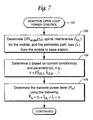
Fig. 7 in flowchart format. Themobile station 30 detects a target carrier-to-interference ratio γ t broadcast from a base station over a downlink access channel. The target CIR γ t may also be predefined in the system, and hence, already known by the mobile station. Themobile station 30 also detects the current uplink interference estimate ÎUL measured and broadcast by the base station over its corresponding geographic cell together with a downlink pilot (or other broadcast) signal transmit power value. Themobile controller 80 then determines an estimate of the path loss L̂ by taking the difference between the broadcast value of the transmit power at which the downlink pilot signal was actually transmitted from the base station (block 102) and the actual received power of the downlink pilot signal. From these determined parameters γt, ÎUL, and L̂, an open loop transmission power level P̂tx may be determined by themobile controller 80 in accordance with equation (1) above, i.e., P̂tx = γt + ÎUL + L̂. - However, the
mobile station 30, e.g., themobile station controller 80, also determines an cell specific adaptive power parameter, referred to in this example embodiment as a power offset value Δ, based on current conditions and parameters (block 104). The mobile's transmit power is then determined (block 106) in accordance with the following:

- One simple example function for equation (4) is Δ C = A(IULmax - ÎUL.), where A is a constant and IULmax is the maximum allowed uplink interference. Of course, other functions may be used. In general, the lower the interference value(s), the larger Δ C may be. Preferably, the interference in the mobile's current cell should also have a larger effect on Δ C than the interference values for neighboring cells.
- A random access always creates more uplink interference. The other, already-active mobiles therefore need to increase their respective transmit powers to maintain the same target CIR thereby increasing the uplink interference even more. But at low traffic loads, i.e., low IUL, the system can allow this to occur because the IUL will not increase above a maximum allowed value which defines the maximum uplink capacity of the CDMA system. Moreover, the interference created by the random access may be compensated for in other active mobiles in the cell using closed loop power control.
- Hence, for low traffic loads, the parameter Δ C is set higher resulting in a higher transmission power. As illustrated above in
Fig. 3 , this moves the probability density function of the carrier-to-interference ratio to the right of the target CIR resulting in a larger probability of successful random access and a lower packet delay. Low traffic load cases will predictably be quite common since the cellular system will probably be dimensioned for higher traffic load cases which typically occur only during certain busy times. So this higher transmission power will result in improved system performance for the typical traffic scenario. Conversely, at higher traffic loads, when the uplink interference is close to a maximum allowed value, the power offset Δ C is set lower, perhaps even to a negative value as illustrated inFig. 3 to avoid excessive disturbance for other users on the uplink. Although this gives a smaller probability of receipt at the target CIR, and therefore, a lower probability of a successful random access and a longer packet delay, this tradeoff is necessary during high interference periods to ensure continued communications without escalating transmit powers (i.e., the party effect) to the detriment of all users. - The above description explains how the power offset ΔC in accordance with one example of the present invention may be applied in the setting of mobile transmit power for an uplink common channel, (e.g., a RACH channel). In addition, the power offset Δ C may be applied for downlink common channels with open loop power control, (e.g., a FACH channel). In downlink common channels, the path loss and the interference at the mobile station is measured and reported by the mobile to the radio network. Alternatively, the mobile station informs the network of how much more or less the base station transmit power level on FACH should be compared to the broadcast pilot signal transmit power level. After having calculated the FACH transmit power level, the radio network may then apply the power offset Δ C to that transmit power level and adapt it to high or low traffic load conditions as described above for uplink transmissions.
- The mobile's transmit power at random access may also depend on user specific parameters either alone or in addition to uplink interference. For example, the power offset may depend on the particular data packet mode to be employed by the mobile station after the random access. For example, if the mobile station will be allocated a dedicated traffic channel immediately after the random access, the power offset may be set to a higher value to provide a quick random access and thereby facilitate a rapid transfer to a dedicated channel. Dedicated traffic channels have higher capacity and generally employ more precise closed loop power control which creates less interference to the system overall compared to shared or common traffic channels that typically do not employ closed loop power control. In addition, the power offset may depend on a mobile user's subscription. Mobile users may subscribe to a priority access feature resulting in a larger power offset to increase their chances of fast random access and lower delays on common channels. Hence, a user specific power offset Δ U could also be added to set the mobile transmit power in the same way as the cell specific power offset Δ C described above, i.e.,

- The mobile's transmit power at random access may depend still on other factors. As described in the background, part of the error between the received carrier-to-interference ratio (CIR) and the target CIR (γ t ) is due to the inability of the mobile station to actually transmit at the calculated transmit power P̂IX . Instead, the mobile may transmit at an actual power PIX that may differ considerably from the calculated or otherwise desired power P̂tx . The following example variables may have a significant impact on the actual transmission power level despite the transmit
power controller 88 providing a desired transmit power level to the transmitter 90: - mobile station temperature
- actual power level at which the mobile station is currently transmitting
- individual electronic components contained in the specific mobile.
- Such mobile and base station specific errors may be compensated in the present invention using an equipment-specific power offset Δ E . Knowledge of the mobile station specific parameters may be accumulated and stored in the mobile station. Knowledge of base station specific errors may be accumulated and stored for each base station in the mobile station. The mobile station then applies the appropriate compensation.
- In the example that follows, it is assumed that the base station measures the received power level accurately and that the broadcast power level for the base station pilot signal is equal to the actual transmitted power level of the pilot. The example illustrates the mobile station compensating for temperature drift, systematic errors in signal strength detection, and systematic differences between the actual transmitted output power and the assigned output power. Other factors that result in transmit power errors may be compensated for in a similar way.
- During a random access transmission, the base station measures the received random access signal power C from the mobile station, C = Ptx - L , and provides the measured value Ĉ back to the mobile station. The mobile aims at achieving a target received random access signal power Ct equal to Ct = P̂tx- L̂ . From this, the mobile station determines a received signal power error E of


where E(t -1) denotes a previously received signal power error value for this temperature and transmit power and E(t - 2) is the second previous value. The coefficient α (<1) denotes the degree to which Δ E is updated according to new data. - Thus, for a given temperature and absolute power level, the mobile station calculates the compensation term Δ E and adds it to the mobile transmit power in the same way as the cell specific and user specific offsets Δ C and Δ U in equation (5) above, using all, some, or just one of the specific power offsets, e.g.,

- One or more specific power offsets Δ E values are calculated by the
mobile station controller 80. For uplink common channel transmissions, Δ C and Δ U , is preferably calculated in the RNC and broadcast to the mobiles. For downlink common channels transmissions, all power offsets are preferably calculated in the RNC. It may be preferable to have theRNC controller 50 calculate power offsets for each cell, to allow for centralized handling and broadcasting. - While the present invention has been described with respect to particular example embodiments, those skilled in the art will recognize that the present invention is not limited to the specific example embodiments described and illustrated herein. Different formats, embodiments, and adaptations besides those shown and described as well as many modifications, variations, and equivalent arrangements may also be used to implement the invention. For example, the present invention is applicable to both uplink and downlink channels. Moreover, the invention may be used in conjunction with other applications such as power ramping. In the power ramping situation, the present invention may be employed to advantageously decide at which transmit power from which to start ramping.
Claims (31)
- A method for uplink open loop power control for improving communications between a mobile station and a base station over a radio communications channel in a mobile communications system having plural base stations corresponding to coverage cells and plural mobile stations, including the following steps:establishing a predetermined relationship between a desired communications signal and an uplink interference signal;determining an interference value corresponding to uplink interference in one of the cells; anddetermining a signal loss factor associated with a radio path in the cell;determining an adaptive power parameter including at least one of a cell-specific offset depending on the current traffic load in the cell, a user-specific offset depending on a mobile user's subscription type, and an equipment-specific offset depending on equipment related factors; andcalculating a transmission power at which to transmit over the radio communications channel based on the predetermined relationship, the interference value, the signal loss factor, and the adaptive power parameter, such that at lower traffic loads the transmit power level is higher and at higher traffic loads the transmit power level is lower.
- The method in claim 1, wherein the power parameter varies a function of interference in the one cell.
- The method in claim 2, wherein the interference is in an uplink direction from mobile station to base station.
- The method in claim 2, wherein the interference is a function of interference in the one cell and at least one neighboring cell.
- The method in claim 1, further comprising:for lower traffic loads, setting a higher power for transmissions over the communications channel.
- The method in claim 1, further comprising:for higher traffic loads, setting a lower power for transmissions over the communications channel.
- The method in claim 1, wherein the radio communications channel is an access channel.
- The method in claim 7, wherein the access channel is an uplink random access channel (RACH) from the mobile station to a base station in the cell.
- The method in claim 1, wherein the predetermined relationship is a carrier-to-interference ratio determined at a base station.
- The method in claim 1, wherein the signal loss factor is the path loss factor determined on a channel between the mobile station and a base station in the cell.
- The method in claim 1, wherein the one or more user specific parameters include a type of data connection that will be employed between the mobile station and the base station.
- The method in claim 11, wherein the power parameter is larger when the type of date packet communication includes a dedicated connection dedicated to the mobile station and the power parameter is lower when the type of data communication includes a common connection shared by plural mobile stations.
- The method in claim 1, wherein the one or more equipment related factors includes an error in the determined path loss factor or in the determined cell interference.
- The method in claim 1, wherein the one or more equipment related factors includes a transmit power level error.
- The method in claim 1, wherein the one or more equipment related factors includes a mobile station temperature.
- The method in claim 15, further comprising:detecting a current temperature of the mobile station, anddetermining the power parameter corresponding to the detected current temperature.
- The method in claim 1, wherein the one or more equipment related factors includes a compensation value for equipment-related inaccuracies and physical limitations.
- The method in claim 1, wherein delay on a common radio communications channel employed by plural mobile stations to communicate with a base station located in a corresponding geographical cell area is reduced by adapting transmission power based on the traffic load in the cell area.
- The method in claim 18, further comprising:for lower traffic loads, setting a higher power for transmission over the common radio channel.
- The method in claim 18, further comprising:for higher traffic loads, setting a lower power for transmission over the common radio channel.
- The method in claim 1, wherein the radio communications channel is an uplink access channel.
- The method in claim 1, wherein the communications channel provides communications between a base station having a corresponding cell area and one or more mobile stations, and the adaptive power parameter is a function of one or more specific characteristics of the mobile stations active in the cell.
- The method in claim 1, wherein the communications channel provides communications between a base station having a corresponding cell area and one or more mobile stations, and wherein the adaptive power parameter is a function of traffic load in the cell.
- The method in claim 1, wherein the communications channel provides communications between a base station having a corresponding cell area and one or more mobile stations, and wherein the adaptive power parameter is a function of interference in the cell and in a neighboring cell.
- The method in claim 1, wherein the communications channel provides communications between a base station having a corresponding cell area and one or more mobile stations, and wherein the adaptive power parameter is a function of user specific factors.
- The method in claim 1, wherein the communications channel provides communications between a base station having a corresponding cell area and one or more mobile stations, and wherein the adaptive power parameter is a function of equipment-related factors.
- A radio station (16-18) capable of communicating over a radio channel associated with a geographical cell (S1-S6) including a transmitter (64-70, 90) for transmitting data packets over the radio channel and a receiver (64-70, 84, 85) for receiving data packets over the radio channel, including
a controller (72, 88) adapted for establishing a predetermined relationship between a desired communications signal and an uplink interference signal;
determining an interference value corresponding to uplink interference in one of the cells; and
determining a signal loss factor associated with a radio path in the cell;
determining an adaptive power parameter including at least one of a cell-specific offset depending on the current traffic load in the cell, a user-specific offset depending on a mobile user's subscription type, and an equipment-specific offset depending on equipment related factors; and
calculating a transmission power at which to transmit over the radio communications channel based on the predetermined relationship, the interference value, the signal loss factor, and the adaptive power parameter, such that at lower traffic loads the transmit power level is higher and at higher traffic loads the transmit power level is lower. - The radio station in claim 27, wherein the controller includes a transmit power controller coupled to the transmitter and a station controller controlling the transmitter, receiver, and transmit power controller.
- The radio station in claim 27, wherein the radio station uses code division multiple access (CDMA) and the receiver is a RAKE receiver.
- The radio station in claim 27, wherein the radio station is a mobile station and the cell is associated with a base station.
- The radio station in claim 27, wherein the adapted power parameter is a function of two or more of the following:the uplink interference in the cell in which the mobile station is located;a current packet data mode of the mobile station,a current subscription of the mobile station,a current temperature of the mobile station,a current base station used for random access by the mobile station,the mobile station equipment,the interference in other cells adjacent to the cell in which the mobile station is located, andan error between a target signal level value at which the base station desires to receive signals from the mobile station and an actual signal strength level value.
Applications Claiming Priority (3)
| Application Number | Priority Date | Filing Date | Title |
|---|---|---|---|
| US267686 | 1999-03-15 | ||
| US09/267,686 US6628956B2 (en) | 1999-03-15 | 1999-03-15 | Adaptive power control in a radio communications systems |
| PCT/SE2000/000448 WO2000055976A2 (en) | 1999-03-15 | 2000-03-07 | Adaptive power control in a radio communications system |
Publications (2)
| Publication Number | Publication Date |
|---|---|
| EP1161802A2 EP1161802A2 (en) | 2001-12-12 |
| EP1161802B1 true EP1161802B1 (en) | 2008-05-21 |
Family
ID=23019771
Family Applications (1)
| Application Number | Title | Priority Date | Filing Date |
|---|---|---|---|
| EP00917548A Expired - Lifetime EP1161802B1 (en) | 1999-03-15 | 2000-03-07 | Adaptive power control in a radio communication system |
Country Status (11)
| Country | Link |
|---|---|
| US (1) | US6628956B2 (en) |
| EP (1) | EP1161802B1 (en) |
| JP (1) | JP4426116B2 (en) |
| KR (1) | KR20010113744A (en) |
| CN (1) | CN1192512C (en) |
| AR (1) | AR025829A1 (en) |
| AT (1) | ATE396553T1 (en) |
| AU (1) | AU3850400A (en) |
| DE (1) | DE60038956D1 (en) |
| TW (1) | TW453056B (en) |
| WO (1) | WO2000055976A2 (en) |
Cited By (3)
| Publication number | Priority date | Publication date | Assignee | Title |
|---|---|---|---|---|
| US9516564B2 (en) | 2014-04-25 | 2016-12-06 | At&T Intellectual Property I, L.P. | Enhancement of a cell reselection parameter in heterogeneous networks |
| US9621294B2 (en) | 2014-10-02 | 2017-04-11 | At&T Intellectual Property I, L.P. | Enhancement of inter-cell interference coordination with adaptive reduced-power almost blank subframes based on neighbor cell profile data |
| US9635566B2 (en) | 2014-04-25 | 2017-04-25 | At&T Intellectual Property I, L.P. | Enhancement of access points to support heterogeneous networks |
Families Citing this family (179)
| Publication number | Priority date | Publication date | Assignee | Title |
|---|---|---|---|---|
| GB9906198D0 (en) * | 1999-03-18 | 1999-05-12 | Lucent Technologies Inc | Improved random access channel |
| DE19918371C1 (en) * | 1999-04-22 | 2000-11-02 | Siemens Ag | Stochastic transmission power setting in a channel for random access of a radio communication system |
| GB9912846D0 (en) * | 1999-06-02 | 1999-08-04 | Nokia Telecommunications Oy | A method of controlling power |
| US6996069B2 (en) * | 2000-02-22 | 2006-02-07 | Qualcomm, Incorporated | Method and apparatus for controlling transmit power of multiple channels in a CDMA communication system |
| US6597723B1 (en) | 2000-03-21 | 2003-07-22 | Interdigital Technology Corporation | Weighted open loop power control in a time division duplex communication system |
| US6603797B1 (en) * | 2000-03-22 | 2003-08-05 | Interdigital Technology Corporation | Outer loop/weighted open loop power control in a time division duplex communication system |
| DE10017930A1 (en) * | 2000-04-11 | 2001-11-15 | Siemens Ag | Method for controlling the transmission power in a radio SIGM communication system |
| GB0012258D0 (en) * | 2000-05-19 | 2000-07-12 | Fujitsu Ltd | Transmission rate changes in communications networks |
| DE10029427A1 (en) * | 2000-06-15 | 2001-12-20 | Siemens Ag | Transmission power control method between base station and data terminals by allocating respective transmission powers to packet data traffic channels |
| KR100387057B1 (en) * | 2000-07-04 | 2003-06-12 | 삼성전자주식회사 | Method and apparatus for determining reverse data rate in mobile communication system |
| JP3848068B2 (en) * | 2000-09-12 | 2006-11-22 | 株式会社エヌ・ティ・ティ・ドコモ | CDMA radio transmission apparatus, CDMA radio transmission / reception system, transmission power control method for CDMA radio transmission apparatus, and transmission power control method for radio transmission apparatus in CDMA radio transmission / reception system |
| CN1159931C (en) * | 2000-10-02 | 2004-07-28 | 株式会社Ntt都科摩 | Mobile communication system, base mobile station, and method for controlling mobile communication |
| US20020075869A1 (en) * | 2000-12-18 | 2002-06-20 | Shah Tushar Ramanlal | Integration of network, data link, and physical layer to adapt network traffic |
| US7333512B2 (en) * | 2000-12-18 | 2008-02-19 | Rmi Corporation | Dynamic mixing TDM data with data packets |
| KR100468574B1 (en) * | 2000-12-28 | 2005-01-31 | 엘지전자 주식회사 | Method for deciding initial power of terminal in high speed wireless packet data transmission |
| US20020094833A1 (en) * | 2001-01-12 | 2002-07-18 | Telefonaktiebolaget Lm Ericsson (Publ). | Downlink power control of a common transport channel |
| FR2819658B1 (en) * | 2001-01-12 | 2004-04-09 | Cit Alcatel | METHOD FOR MANAGING PROCESSING RESOURCES IN A MOBILE RADIO COMMUNICATION SYSTEM |
| KR100433893B1 (en) * | 2001-01-15 | 2004-06-04 | 삼성전자주식회사 | A power control method in narrow band time division duplexing code division multiple access communication system and apparatus thereof |
| US6748196B2 (en) * | 2001-01-30 | 2004-06-08 | Kon-Hee Lee | Transmit output controlling circuit and method of a wireless mobile communication system |
| SE0100476D0 (en) * | 2001-02-12 | 2001-02-12 | Ericsson Telefon Ab L M | Method and system of throughput control |
| US6970716B2 (en) | 2001-02-22 | 2005-11-29 | Telefonaktiebolaget Lm Ericsson (Publ) | Power control for downlink shared channel in radio access telecommunications network |
| US7006483B2 (en) | 2001-02-23 | 2006-02-28 | Ipr Licensing, Inc. | Qualifying available reverse link coding rates from access channel power setting |
| US6937641B2 (en) * | 2001-02-28 | 2005-08-30 | Golden Bridge Technology, Inc. | Power-controlled random access |
| US7151740B2 (en) * | 2001-02-28 | 2006-12-19 | Cingular Wireless Ii, Llc | Transmit power control for an OFDM-based wireless communication system |
| US6587697B2 (en) * | 2001-05-14 | 2003-07-01 | Interdigital Technology Corporation | Common control channel uplink power control for adaptive modulation and coding techniques |
| AU2007202683B2 (en) * | 2001-05-14 | 2010-10-28 | Interdigital Technology Corporation | Common control channel uplink power control for adaptive modulation and coding techniques |
| US6850500B2 (en) * | 2001-05-15 | 2005-02-01 | Interdigital Technology Corporation | Transmission power level estimation |
| US6957071B1 (en) * | 2001-07-18 | 2005-10-18 | Cisco Technology, Inc. | Method and system for managing wireless bandwidth resources |
| JP2003087842A (en) * | 2001-09-13 | 2003-03-20 | Nec Corp | Hand-over system in code division multiple access communication system and its system |
| GB2381417A (en) * | 2001-10-24 | 2003-04-30 | Ipwireless Inc | Transmission power control based on path loss |
| US7171229B2 (en) * | 2001-10-31 | 2007-01-30 | Koninklijke Philips Electronics N.V. | Method for operating a radio communication system |
| US6950670B2 (en) * | 2001-10-31 | 2005-09-27 | At&T Corp. | Wireless network having joint power and data rate adaptation |
| KR100811043B1 (en) | 2001-11-16 | 2008-03-06 | 엘지전자 주식회사 | method for controlling transmission power of SCH and HI in mobile communication |
| JP2003163632A (en) * | 2001-11-29 | 2003-06-06 | Hitachi Ltd | Radio communication equipment changing transmission rate of signals to be transmitted to terminal or transmission power and signal transmission method therefor |
| GB2383232B (en) * | 2001-12-14 | 2005-09-21 | Ubinetics Ltd | A radiotelephone system and a method of operating same |
| KR100832117B1 (en) * | 2002-02-17 | 2008-05-27 | 삼성전자주식회사 | Apparatus for transmitting/receiving uplink power offset in communication system using high speed downlink packet access scheme |
| US6778812B1 (en) * | 2002-05-24 | 2004-08-17 | Interdigital Technology Communication | System and method for call admission control |
| AU2002309078A1 (en) * | 2002-06-04 | 2003-12-19 | Nokia Corporation | Power based radio resource management |
| US20050227699A1 (en) * | 2002-06-26 | 2005-10-13 | Harmen Schreuder | Method and network element for optimisation of radio resource utilisation in radio access network |
| JP2004064142A (en) | 2002-07-24 | 2004-02-26 | Ntt Docomo Inc | Transmission power control method, radio communication system suitably adopting the same, radio base station, and mobile station |
| US20050227763A1 (en) * | 2004-03-31 | 2005-10-13 | Microsoft Corporation | Game controller power management |
| WO2004023674A1 (en) | 2002-09-06 | 2004-03-18 | Nokia Corporation | Antenna selection method |
| US8504054B2 (en) | 2002-09-10 | 2013-08-06 | Qualcomm Incorporated | System and method for multilevel scheduling |
| US7630321B2 (en) | 2002-09-10 | 2009-12-08 | Qualcomm Incorporated | System and method for rate assignment |
| CN100452674C (en) * | 2002-09-30 | 2009-01-14 | Ut斯达康(中国)有限公司 | Open-loop power control method for common channel in upstream and downstream links of CDMA system |
| US7120392B2 (en) * | 2002-10-11 | 2006-10-10 | Glowlink Communications Technology, Inc. | Uplink power control using loopback communications carriers |
| AU2002340984A1 (en) | 2002-11-07 | 2004-06-07 | Nokia Corporation | Data transmission method involving estimation of cell power increase in the current and neighbouring cells due to a capacity request |
| US6748235B1 (en) * | 2002-11-12 | 2004-06-08 | Interdigital Technology Corporation | Power control during a transmission pause |
| US20040116146A1 (en) * | 2002-12-13 | 2004-06-17 | Sadowsky John S. | Cellular system with link diversity feedback |
| CN1512800A (en) * | 2002-12-30 | 2004-07-14 | �ʼҷ����ֵ��ӹɷ�����˾ | Self adaption step-size power control system and method for radio communication system |
| US8165148B2 (en) | 2003-01-13 | 2012-04-24 | Qualcomm Incorporated | System and method for rate assignment |
| US7239884B2 (en) * | 2003-01-23 | 2007-07-03 | Motorola, Inc. | Method for providing improved access times for a communication device |
| KR100742456B1 (en) * | 2003-02-17 | 2007-07-25 | 교세라 가부시키가이샤 | Wireless unit |
| JP3922571B2 (en) * | 2003-03-26 | 2007-05-30 | ソニー株式会社 | Information processing apparatus, information processing method, recording medium, and program |
| EP1478200B1 (en) * | 2003-05-14 | 2008-12-10 | Research In Motion Limited | Apparatus and method of determining the status of a requested service |
| FI20030892A0 (en) * | 2003-06-13 | 2003-06-13 | Nokia Corp | Procedure for managing uplink radio resources in a CDMA telecommunication system and arrangement |
| FR2856862B1 (en) * | 2003-06-27 | 2005-09-09 | Nortel Networks Ltd | METHOD FOR CONTROLLING RELATIVE POWER OF RADIO SIGNALS EMITTED IN MACRODIVERSITY MODE, AND RADIO NETWORK CONTROLLER FOR IMPLEMENTING THE METHOD |
| US6970713B2 (en) | 2003-07-09 | 2005-11-29 | Interdigital Technology Corporation | Method and system wherein timeslots allocated for common control channels may be reused for user traffic |
| US6970437B2 (en) | 2003-07-15 | 2005-11-29 | Qualcomm Incorporated | Reverse link differentiated services for a multiflow communications system using autonomous allocation |
| US20050047366A1 (en) * | 2003-08-25 | 2005-03-03 | Motorola, Inc. | Random access communication opportunity method |
| US7630731B2 (en) * | 2003-09-08 | 2009-12-08 | Lundby Stein A | Apparatus, system, and method for managing reverse link communication |
| US7353025B2 (en) | 2003-09-29 | 2008-04-01 | Lg Electronics Inc. | Uplink scheduling method of wireless mobile communication system |
| US7724701B2 (en) * | 2003-09-30 | 2010-05-25 | Qualcomm Incorporated | Method and apparatus for controlling reverse link data rate of a mobile station in a communication system with reverse link common rate control |
| CN1914824B (en) * | 2003-11-13 | 2010-05-12 | Lg电子株式会社 | Transmission power control apparatus in wireless communication system and method therefor |
| US7302276B2 (en) * | 2003-11-25 | 2007-11-27 | Telefonaktiebolaget L M Ericsson (Publ) | Method and system for determining uplink/downlink path-loss difference |
| CN103220806B (en) * | 2003-12-19 | 2016-06-01 | 艾利森电话股份有限公司 | For the connection set up in multihop network quick/opportunistic distributed resource redistributes |
| WO2005060170A1 (en) * | 2003-12-19 | 2005-06-30 | Telefonaktiebolaget Lm Ericsson (Publ) | Fast/opportunistic distributed resource reallocation for established connections in a multihop network |
| US8923163B2 (en) * | 2003-12-19 | 2014-12-30 | Telefonaktiebolaget L M Ericsson (Publ) | Fast opportunistic distributed resource reallocation for established connections in a multihop network |
| US7668562B1 (en) * | 2004-04-20 | 2010-02-23 | Trimble Navigation Limited | Method and apparatus for GPS geofencing of mobile transmissions |
| US7437175B2 (en) * | 2004-05-06 | 2008-10-14 | Telefonaktiebolaget L M Ericsson (Publ) | Synchronization detection methods and apparatus |
| FI20045195A0 (en) * | 2004-05-27 | 2004-05-27 | Nokia Corp | Procedure and arrangement for uplink scheduling |
| US8452316B2 (en) * | 2004-06-18 | 2013-05-28 | Qualcomm Incorporated | Power control for a wireless communication system utilizing orthogonal multiplexing |
| US7536626B2 (en) * | 2004-06-18 | 2009-05-19 | Qualcomm Incorporated | Power control using erasure techniques |
| US7594151B2 (en) * | 2004-06-18 | 2009-09-22 | Qualcomm, Incorporated | Reverse link power control in an orthogonal system |
| US7197692B2 (en) * | 2004-06-18 | 2007-03-27 | Qualcomm Incorporated | Robust erasure detection and erasure-rate-based closed loop power control |
| US8897828B2 (en) | 2004-08-12 | 2014-11-25 | Intellectual Ventures Holding 81 Llc | Power control in a wireless communication system |
| US8423070B2 (en) * | 2004-09-17 | 2013-04-16 | Volkmar Scharf-Katz | Method and system to model TCP throughput, assess power control measures, and compensate for fading and path loss, for highly mobile broadband systems |
| JP4249108B2 (en) * | 2004-09-27 | 2009-04-02 | 富士通株式会社 | Wireless system |
| US7203494B2 (en) * | 2004-11-12 | 2007-04-10 | Motorola, Inc. | Optimizing radio communication efficiency and methods thereof |
| US7693491B2 (en) * | 2004-11-30 | 2010-04-06 | Broadcom Corporation | Method and system for transmitter output power compensation |
| CN100365957C (en) * | 2004-12-02 | 2008-01-30 | 华为技术有限公司 | Reverse load control method |
| US7860176B2 (en) * | 2004-12-10 | 2010-12-28 | Nortel Networks Limited | OFDM system with reverse link interference estimation |
| CN100415041C (en) * | 2004-12-17 | 2008-08-27 | 华为技术有限公司 | Method for dynamically adjusting CDMA system communication quality |
| EP1694091B1 (en) * | 2005-02-16 | 2016-04-13 | Nokia Technologies Oy | Resource control method for enhancing time-based frequency reuse in a mobile communications system |
| US7899463B2 (en) | 2005-02-16 | 2011-03-01 | Nokia Corporation | Communication resource control enhancing time-based frequency reuse |
| US8488459B2 (en) * | 2005-03-04 | 2013-07-16 | Qualcomm Incorporated | Power control and quality of service (QoS) implementation in a communication system |
| CN101278496B (en) * | 2005-03-15 | 2017-04-12 | 高通股份有限公司 | Method and device for conducting power control through interference information from multiple sectors |
| US7742444B2 (en) * | 2005-03-15 | 2010-06-22 | Qualcomm Incorporated | Multiple other sector information combining for power control in a wireless communication system |
| US7512412B2 (en) | 2005-03-15 | 2009-03-31 | Qualcomm, Incorporated | Power control and overlapping control for a quasi-orthogonal communication system |
| US8848574B2 (en) | 2005-03-15 | 2014-09-30 | Qualcomm Incorporated | Interference control in a wireless communication system |
| US8942639B2 (en) * | 2005-03-15 | 2015-01-27 | Qualcomm Incorporated | Interference control in a wireless communication system |
| KR100946099B1 (en) * | 2005-03-15 | 2010-03-10 | 콸콤 인코포레이티드 | Interference information from multiple sectors for power control |
| US8717912B2 (en) * | 2005-04-20 | 2014-05-06 | Mitsubishi Electric Corporation | Communication quality judgment method, mobile station, base station, and Communications System |
| JP4498973B2 (en) * | 2005-05-11 | 2010-07-07 | 株式会社日立製作所 | Wireless communication apparatus, wireless communication apparatus control method, and program |
| US8750908B2 (en) | 2005-06-16 | 2014-06-10 | Qualcomm Incorporated | Quick paging channel with reduced probability of missed page |
| US9055552B2 (en) | 2005-06-16 | 2015-06-09 | Qualcomm Incorporated | Quick paging channel with reduced probability of missed page |
| US7433703B2 (en) * | 2005-06-16 | 2008-10-07 | Lucent Technologies Inc. | Method for allocating resources in a wireless communication system |
| EP1734664B1 (en) * | 2005-06-17 | 2008-08-20 | Fujitsu Limited | Power control in multi-hop communication system |
| US7519329B2 (en) * | 2005-07-01 | 2009-04-14 | Research In Motion Limited | Determination of antenna noise temperature for handheld wireless devices |
| US7965789B2 (en) | 2005-08-22 | 2011-06-21 | Qualcomm Incorporated | Reverse link power control for an OFDMA system |
| FI20055469A0 (en) * | 2005-09-02 | 2005-09-02 | Nokia Corp | Procedure and arrangements for controlling radio resources |
| IL170925A (en) * | 2005-09-18 | 2010-12-30 | Alvarion Ltd | Method and device for transmission power control in wireless communications networks |
| US20070082620A1 (en) * | 2005-10-06 | 2007-04-12 | Interdigital Technology Corporation | Method and apparatus for controlling uplink transmission power for ofdma based evolved utra |
| US20090207790A1 (en) | 2005-10-27 | 2009-08-20 | Qualcomm Incorporated | Method and apparatus for settingtuneawaystatus in an open state in wireless communication system |
| US8331285B2 (en) | 2005-10-27 | 2012-12-11 | Qualcomm Incorporated | Method and apparatus of establishing access channel in wireless communication systems |
| WO2007050926A2 (en) | 2005-10-27 | 2007-05-03 | Qualcomm Incorporated | Method and apparatus for estimating reverse link loading in a wireless communication system |
| GB2445336B (en) * | 2005-11-04 | 2010-12-08 | Nec Corp | Wireless communication system and method of controlling a transmission power |
| KR100726810B1 (en) * | 2005-12-08 | 2007-06-11 | 한국전자통신연구원 | Method and apparatus for contention technique using power control on ofdm system |
| CN1988407B (en) * | 2005-12-22 | 2010-07-07 | 大唐移动通信设备有限公司 | Open ring power control method for base station and its physical random cut-in channel |
| US8098644B2 (en) * | 2006-01-18 | 2012-01-17 | Motorola Mobility, Inc. | Method and apparatus for uplink resource allocation in a frequency division multiple access communication system |
| KR100819273B1 (en) * | 2006-01-20 | 2008-04-03 | 삼성전자주식회사 | method and apparatus for open loop power control in communication system |
| CN101009541B (en) * | 2006-01-23 | 2011-04-20 | 华为技术有限公司 | Disturbance coordination method and device of OFDMA system |
| US20090036153A1 (en) * | 2006-02-06 | 2009-02-05 | Junya Yamazaki | Base station and communication system |
| US8150412B2 (en) * | 2006-03-06 | 2012-04-03 | Alcatel Lucent | Interference mitigation in a wireless communication system |
| EP2011247B1 (en) * | 2006-04-27 | 2013-07-03 | TELEFONAKTIEBOLAGET LM ERICSSON (publ) | Power control in a wireless system having multiple interfering communication resources |
| KR100948548B1 (en) * | 2006-05-24 | 2010-03-19 | 삼성전자주식회사 | Apparatus and method for controlling uplink power in a broadband wireless access communication system |
| US7738907B2 (en) * | 2006-06-20 | 2010-06-15 | Motorola, Inc. | Method and apparatus for uplink power control in a frequency division multiple access communication system |
| US8046019B2 (en) * | 2006-08-04 | 2011-10-25 | Futurewei Technologies, Inc. | Method and system for optimal allocation of uplink transmission power in communication networks |
| KR100765892B1 (en) * | 2006-08-30 | 2007-10-10 | 주식회사 팬택 | Method of controlling inter-cell interference for a mobile communication system |
| US8442572B2 (en) | 2006-09-08 | 2013-05-14 | Qualcomm Incorporated | Method and apparatus for adjustments for delta-based power control in wireless communication systems |
| US8670777B2 (en) * | 2006-09-08 | 2014-03-11 | Qualcomm Incorporated | Method and apparatus for fast other sector interference (OSI) adjustment |
| US8195097B2 (en) * | 2006-09-08 | 2012-06-05 | Qualcomm Incorporated | Serving sector interference broadcast and corresponding RL traffic power control |
| RU2427106C2 (en) * | 2006-10-03 | 2011-08-20 | Квэлкомм Инкорпорейтед | Random access signalling transmission for system access in wireless communication |
| US20080096557A1 (en) * | 2006-10-04 | 2008-04-24 | Nokia Corporation | Efficient and dynamic identification of allocations in a wireless packet communication system |
| CN101523775B (en) * | 2006-10-06 | 2012-04-11 | 艾利森电话股份有限公司 | Method and arrangement for noise floor estimation |
| US8274952B2 (en) * | 2006-10-10 | 2012-09-25 | Alcatel Lucent | Transmission power management |
| EP1914907A1 (en) * | 2006-10-16 | 2008-04-23 | STMicroelectronics N.V. | Transmit power control based on path loss estimation in a multicarrier system |
| KR101086604B1 (en) | 2006-11-01 | 2011-11-23 | 콸콤 인코포레이티드 | Inter-cell power control for interference management |
| KR100948797B1 (en) * | 2006-12-11 | 2010-03-24 | 삼성전자주식회사 | Apparatus and method for scheduling in mobile communication system |
| US8325654B2 (en) * | 2006-12-28 | 2012-12-04 | Futurewei Technologies, Inc. | Integrated scheduling and power control for the uplink of an OFDMA network |
| US7917164B2 (en) * | 2007-01-09 | 2011-03-29 | Alcatel-Lucent Usa Inc. | Reverse link power control |
| GB2447439B (en) | 2007-02-02 | 2012-01-25 | Ubiquisys Ltd | Access point power control |
| WO2008103773A1 (en) * | 2007-02-20 | 2008-08-28 | Haiyun Tang | Digital predistortion for cognitive radio |
| US9774086B2 (en) * | 2007-03-02 | 2017-09-26 | Qualcomm Incorporated | Wireless power apparatus and methods |
| US8744510B2 (en) * | 2007-03-13 | 2014-06-03 | Pranav Dayal | Power control method and apparatus for wireless communications |
| US9295003B2 (en) | 2007-03-19 | 2016-03-22 | Apple Inc. | Resource allocation in a communication system |
| WO2008117203A2 (en) * | 2007-03-28 | 2008-10-02 | Nxp B.V. | Wireless transmission power control method and system |
| JP5042320B2 (en) | 2007-03-29 | 2012-10-03 | エルジー エレクトロニクス インコーポレイティド | Sounding reference signal transmission method in wireless communication system |
| KR101380558B1 (en) | 2007-06-19 | 2014-04-02 | 엘지전자 주식회사 | Method of Transmitting Sounding Reference Signal |
| KR101397039B1 (en) * | 2007-08-14 | 2014-05-20 | 엘지전자 주식회사 | Signal Transmission Method Using CDM Against The Effect Of Channel Estimation Error in Transmit Diversity System |
| KR101430267B1 (en) * | 2007-08-14 | 2014-08-18 | 엘지전자 주식회사 | Method of Transmitting Data in a Wireless Communication System |
| RU2439809C2 (en) * | 2007-08-14 | 2012-01-10 | Эл Джи Электроникс Инк. | Method of acquiring resource region information for phich and method of receiving pdcch |
| KR101507785B1 (en) | 2007-08-16 | 2015-04-03 | 엘지전자 주식회사 | A method for transmitting channel quality information in a MIMO (Multiple Input Multiple Output) system |
| KR101405974B1 (en) * | 2007-08-16 | 2014-06-27 | 엘지전자 주식회사 | Methods for transmitting codewords in multiple input multiple output system |
| JP5145852B2 (en) * | 2007-10-15 | 2013-02-20 | 日本電気株式会社 | Coefficient determination device, radio communication system, coefficient determination method, and coefficient determination program |
| US8260341B2 (en) * | 2007-11-02 | 2012-09-04 | Interdigital Patent Holdings, Inc. | Power control for combined dynamically and persistently scheduled PUSCH in E-UTRA |
| US8718694B2 (en) * | 2007-12-07 | 2014-05-06 | Interdigital Patent Holdings, Inc. | Method and apparatus of signaling and procedure to support uplink power level determination |
| US7962631B2 (en) * | 2007-12-21 | 2011-06-14 | Yahoo! Inc. | Method for determining network proximity for global traffic load balancing using passive TCP performance instrumentation |
| CN101933376B (en) * | 2008-01-10 | 2013-10-09 | 艾利森电话股份有限公司 | Method and arrangement for saving radio resources by determining power offset values in the user equipment |
| US8559320B2 (en) * | 2008-03-19 | 2013-10-15 | Avaya Inc. | Method and apparatus for measuring voice quality on a VoIP network |
| JP5440494B2 (en) * | 2008-03-31 | 2014-03-12 | 日本電気株式会社 | Base station apparatus, radio resource control method, radio station control program, and radio communication system |
| US8126403B2 (en) * | 2008-04-23 | 2012-02-28 | Telefonaktiebolaget Lm Ericsson (Publ) | Estimating and limiting inter-cell interference |
| US8446256B2 (en) * | 2008-05-19 | 2013-05-21 | Sirit Technologies Inc. | Multiplexing radio frequency signals |
| CN101594618B (en) * | 2008-05-27 | 2011-02-23 | 中兴通讯股份有限公司 | Method for configuring adjacent districts in self-adapting mode in wireless network |
| JP2008278530A (en) * | 2008-06-18 | 2008-11-13 | Nokia Corp | Antenna selecting method |
| US9420548B2 (en) * | 2008-07-31 | 2016-08-16 | Qualcomm Incorporated | Dynamic IoT setpoints and interference control |
| US9031044B2 (en) | 2008-08-20 | 2015-05-12 | Qualcomm Incorporated | Power control for wireless LAN stations |
| US20110077044A1 (en) * | 2008-08-20 | 2011-03-31 | Qualcomm Incorporated | Power control for wireless lan stations |
| CN102160431A (en) * | 2008-09-22 | 2011-08-17 | 株式会社Ntt都科摩 | Mobile station and wireless base station |
| KR101021660B1 (en) * | 2008-10-28 | 2011-03-17 | 서울대학교산학협력단 | Wireless communication system in multi-cell and multi-antenna environments and method thereof |
| US8219136B2 (en) * | 2009-02-09 | 2012-07-10 | Intel Corporation | Techniques to determine transmitter power |
| US8385832B2 (en) * | 2009-03-13 | 2013-02-26 | Telefonaktiebolaget Lm Ericsson (Publ) | Inter-cell interference control in an uplink multi-carrier radio communications system |
| ES2360328B1 (en) * | 2009-04-23 | 2012-05-08 | Vodafone España S.A.U | TRANSMISSION OF THE PILOT CHANNEL IN A CELLULAR COMMUNICATION NETWORK. |
| GB2471681B (en) * | 2009-07-07 | 2011-11-02 | Ubiquisys Ltd | Interference mitigation in a femtocell access point |
| GB2472597B (en) | 2009-08-11 | 2012-05-16 | Ubiquisys Ltd | Power setting |
| US20120176998A1 (en) * | 2009-09-24 | 2012-07-12 | Robert Muellner | Method for Dynamically Controlling an Uplink Transmission Power of a User Equipment |
| KR101682030B1 (en) * | 2010-02-18 | 2016-12-05 | 삼성전자주식회사 | Method and apparatus for controlling transmission power of base station in wireless communication system |
| WO2011149391A1 (en) | 2010-05-26 | 2011-12-01 | Telefonaktiebolaget L M Ericsson (Publ) | A method and a device for increased bit rate |
| CN102202399B (en) * | 2011-05-18 | 2013-09-11 | 大唐移动通信设备有限公司 | Method for adjusting channel expecting carrier-to-interference ratio and apparatus thereof |
| CN102726106B (en) * | 2011-11-28 | 2015-08-19 | 华为技术有限公司 | The defining method of power offset parameter and device |
| JP2013135332A (en) * | 2011-12-26 | 2013-07-08 | Sharp Corp | Base station device, allowable number of duplication determination method, allowable number of duplication determination program, mobile station device, allowable number of duplication notification method, and allowable number of duplication notification program |
| US8897829B2 (en) * | 2013-02-01 | 2014-11-25 | Nvidia Corporation | Controlling transmit power in a wireless device |
| US10165524B2 (en) | 2013-12-16 | 2018-12-25 | Telefonaktiebolaget Lm Ericsson (Publ) | Method and apparatus for uplink and/or downlink power control in a radio communication network |
| CN104980944B (en) * | 2014-04-04 | 2018-12-07 | 中国移动通信集团浙江有限公司 | The method and apparatus that the downlink power control of a kind of pair of data service is configured |
| US9854527B2 (en) * | 2014-08-28 | 2017-12-26 | Apple Inc. | User equipment transmit duty cycle control |
| US9572110B1 (en) | 2015-12-30 | 2017-02-14 | Motorola Solutions, Inc. | Method and apparatus for transmit power control by a deployable network in a wireless communication system |
| ES2907135T3 (en) * | 2017-03-24 | 2022-04-22 | Huawei Tech Co Ltd | Power control for uplink transmissions |
| US10177445B1 (en) * | 2017-07-05 | 2019-01-08 | National Chung Shan Institute Of Science And Technology | Communication structure |
| WO2021044637A1 (en) * | 2019-09-06 | 2021-03-11 | 株式会社Nttドコモ | Terminal |
Family Cites Families (23)
| Publication number | Priority date | Publication date | Assignee | Title |
|---|---|---|---|---|
| US4868795A (en) * | 1985-08-05 | 1989-09-19 | Terra Marine Engineering, Inc. | Power leveling telemetry system |
| JPS63226124A (en) * | 1986-10-29 | 1988-09-20 | Oki Electric Ind Co Ltd | Level control circuit for radio equipment |
| US5267262A (en) | 1989-11-07 | 1993-11-30 | Qualcomm Incorporated | Transmitter power control system |
| US5485486A (en) * | 1989-11-07 | 1996-01-16 | Qualcomm Incorporated | Method and apparatus for controlling transmission power in a CDMA cellular mobile telephone system |
| DE9102747U1 (en) * | 1990-12-21 | 1991-05-23 | Siemens Ag, 8000 Muenchen, De | |
| US5107487A (en) | 1991-05-28 | 1992-04-21 | Motorola, Inc. | Power control of a direct sequence CDMA radio |
| EP0565507A3 (en) | 1992-04-10 | 1994-11-30 | Ericsson Ge Mobile Communicat | Power control for random access call set-up in a mobile telephone system |
| US5574982A (en) | 1993-05-14 | 1996-11-12 | Telefonaktiebolaget Lm Ericsson | Method and apparatus for regulating a power level of a transmitted radio signal |
| FI97929C (en) * | 1994-02-25 | 1997-03-10 | Nokia Telecommunications Oy | Procedure for transmitting calls with different priorities in cellular radio networks |
| US5491837A (en) | 1994-03-07 | 1996-02-13 | Ericsson Inc. | Method and system for channel allocation using power control and mobile-assisted handover measurements |
| US5551057A (en) | 1994-06-08 | 1996-08-27 | Lucent Technologies Inc. | Cellular mobile radio system power control |
| US5604730A (en) | 1994-07-25 | 1997-02-18 | Qualcomm Incorporated | Remote transmitter power control in a contention based multiple access system |
| WO1997008847A1 (en) * | 1995-08-31 | 1997-03-06 | Nokia Telecommunications Oy | Method and device for controlling transmission power of a radio transmitter in a cellular communication system |
| US5799005A (en) | 1996-04-30 | 1998-08-25 | Qualcomm Incorporated | System and method for determining received pilot power and path loss in a CDMA communication system |
| US5859838A (en) | 1996-07-30 | 1999-01-12 | Qualcomm Incorporated | Load monitoring and management in a CDMA wireless communication system |
| US5805585A (en) * | 1996-08-22 | 1998-09-08 | At&T Corp. | Method for providing high speed packet data services for a wireless system |
| FI106759B (en) * | 1996-11-13 | 2001-03-30 | Nokia Mobile Phones Ltd | Mobile transmit power limiting system |
| US5842114A (en) * | 1997-02-12 | 1998-11-24 | Interdigital Technology Corporation | Global channel power control to minimize spillover in a wireless communication environment |
| JP2000509238A (en) * | 1997-02-13 | 2000-07-18 | ノキア テレコミュニカシオンス オサケ ユキチュア | Directional wireless communication method and apparatus |
| US6091966A (en) * | 1997-09-29 | 2000-07-18 | Ericsson, Inc. | Dual-band, dual-mode power amplifier |
| US6128506A (en) * | 1997-09-24 | 2000-10-03 | Telefonaktiebolaget Lm Ericsson | Integrated power control and congestion control in a communication system |
| US6169906B1 (en) * | 1998-03-24 | 2001-01-02 | Motorola, Inc. | Method of transmitting messages in a dispatch call |
| US6160996A (en) * | 1998-03-31 | 2000-12-12 | Lucent Technologies Inc. | Method for adaptively controlling amplifier linearization devices |
-
1999
- 1999-03-15 US US09/267,686 patent/US6628956B2/en not_active Expired - Lifetime
-
2000
- 2000-03-07 JP JP2000605313A patent/JP4426116B2/en not_active Expired - Fee Related
- 2000-03-07 KR KR1020017011649A patent/KR20010113744A/en not_active Application Discontinuation
- 2000-03-07 CN CNB008076219A patent/CN1192512C/en not_active Expired - Fee Related
- 2000-03-07 AT AT00917548T patent/ATE396553T1/en not_active IP Right Cessation
- 2000-03-07 WO PCT/SE2000/000448 patent/WO2000055976A2/en not_active Application Discontinuation
- 2000-03-07 AU AU38504/00A patent/AU3850400A/en not_active Abandoned
- 2000-03-07 EP EP00917548A patent/EP1161802B1/en not_active Expired - Lifetime
- 2000-03-07 DE DE60038956T patent/DE60038956D1/en not_active Expired - Lifetime
- 2000-03-15 TW TW089104717A patent/TW453056B/en not_active IP Right Cessation
- 2000-03-15 AR ARP000101139A patent/AR025829A1/en unknown
Non-Patent Citations (1)
| Title |
|---|
| S. SOLIMAN ET AL.: "CDMA Reverse link open loop power control", COMMUNICATIONS FOR GLOBAL USERS, 6 December 1992 (1992-12-06), Orlando, pages 69 - 73, XP000357763 * |
Cited By (6)
| Publication number | Priority date | Publication date | Assignee | Title |
|---|---|---|---|---|
| US9516564B2 (en) | 2014-04-25 | 2016-12-06 | At&T Intellectual Property I, L.P. | Enhancement of a cell reselection parameter in heterogeneous networks |
| US9635566B2 (en) | 2014-04-25 | 2017-04-25 | At&T Intellectual Property I, L.P. | Enhancement of access points to support heterogeneous networks |
| US10536880B2 (en) | 2014-04-25 | 2020-01-14 | At&T Intellectual Property I, L.P. | Enhancement of a cell reselection parameter in heterogeneous networks |
| US9621294B2 (en) | 2014-10-02 | 2017-04-11 | At&T Intellectual Property I, L.P. | Enhancement of inter-cell interference coordination with adaptive reduced-power almost blank subframes based on neighbor cell profile data |
| US10243622B2 (en) | 2014-10-02 | 2019-03-26 | At&T Intellectual Property I, L.P. | Enhancement of inter-cell interference coordination with adaptive reduced-power almost blank subframes based on neighbor cell profile data |
| US10680681B2 (en) | 2014-10-02 | 2020-06-09 | At&T Mobility Ii Llc | Enhancement of inter-cell interference coordination with adaptive reduced-power almost blank subframes based on neighbor cell profile data |
Also Published As
| Publication number | Publication date |
|---|---|
| JP2002539707A (en) | 2002-11-19 |
| ATE396553T1 (en) | 2008-06-15 |
| KR20010113744A (en) | 2001-12-28 |
| WO2000055976A3 (en) | 2001-04-12 |
| CN1192512C (en) | 2005-03-09 |
| JP4426116B2 (en) | 2010-03-03 |
| DE60038956D1 (en) | 2008-07-03 |
| US6628956B2 (en) | 2003-09-30 |
| AR025829A1 (en) | 2002-12-18 |
| AU3850400A (en) | 2000-10-04 |
| EP1161802A2 (en) | 2001-12-12 |
| CN1350730A (en) | 2002-05-22 |
| US20020077138A1 (en) | 2002-06-20 |
| TW453056B (en) | 2001-09-01 |
| WO2000055976A2 (en) | 2000-09-21 |
Similar Documents
| Publication | Publication Date | Title |
|---|---|---|
| EP1161802B1 (en) | Adaptive power control in a radio communication system | |
| US6334047B1 (en) | Adaptive power control in a mobile radio communications system | |
| US6580919B1 (en) | CDMA transmission power control capable of preventing call disconnection and degradation of capacity of subscribers | |
| EP0822672B2 (en) | Downlink transmission power control scheme for mobile communication system using site diversity | |
| US6144861A (en) | Downlink power control in a cellular mobile radio communications system | |
| JP4440784B2 (en) | Power control for mobile station in CDMA-TDD system | |
| US6594499B1 (en) | Downlink power control in a cellular telecommunications network | |
| US20030058821A1 (en) | Closed-loop power control method for a code-division multiple-access cellular system | |
| MXPA02011087A (en) | Power control in radio system. | |
| EP1601116A1 (en) | Reverse-link power control overshoot considering mobile station transmission limitations | |
| EP1024606A2 (en) | Open loop power control for wireless mobile stations | |
| US20070218934A1 (en) | Communication Terminal and Transmission Power Control Method | |
| US9008596B2 (en) | Method for regulating the transmission power of a transmitting station, and transmitting station | |
| GB2358109A (en) | Power control during soft handoff | |
| KR100283222B1 (en) | Outer loop power controlling method | |
| CN114189269B (en) | Uplink and downlink power control method and device of intelligent repeater | |
| KR20000011393A (en) | Adaptive load management control for a base station in a cdma cellular wireless communication system |
Legal Events
| Date | Code | Title | Description |
|---|---|---|---|
| PUAI | Public reference made under article 153(3) epc to a published international application that has entered the european phase |
Free format text: ORIGINAL CODE: 0009012 |
|
| 17P | Request for examination filed |
Effective date: 20010919 |
|
| AK | Designated contracting states |
Kind code of ref document: A2 Designated state(s): AT BE CH CY DE DK ES FI FR GB GR IE IT LI LU MC NL PT SE |
|
| AX | Request for extension of the european patent |
Free format text: AL;LT;LV;MK;RO;SI |
|
| RAP1 | Party data changed (applicant data changed or rights of an application transferred) |
Owner name: TELEFONAKTIEBOLAGET LM ERICSSON (PUBL) |
|
| 17Q | First examination report despatched |
Effective date: 20060203 |
|
| 17Q | First examination report despatched |
Effective date: 20060203 |
|
| GRAP | Despatch of communication of intention to grant a patent |
Free format text: ORIGINAL CODE: EPIDOSNIGR1 |
|
| GRAS | Grant fee paid |
Free format text: ORIGINAL CODE: EPIDOSNIGR3 |
|
| GRAA | (expected) grant |
Free format text: ORIGINAL CODE: 0009210 |
|
| AK | Designated contracting states |
Kind code of ref document: B1 Designated state(s): AT BE CH CY DE DK ES FI FR GB GR IE IT LI LU MC NL PT SE |
|
| REG | Reference to a national code |
Ref country code: GB Ref legal event code: FG4D |
|
| REG | Reference to a national code |
Ref country code: CH Ref legal event code: EP |
|
| REF | Corresponds to: |
Ref document number: 60038956 Country of ref document: DE Date of ref document: 20080703 Kind code of ref document: P |
|
| REG | Reference to a national code |
Ref country code: IE Ref legal event code: FG4D |
|
| PG25 | Lapsed in a contracting state [announced via postgrant information from national office to epo] |
Ref country code: ES Free format text: LAPSE BECAUSE OF FAILURE TO SUBMIT A TRANSLATION OF THE DESCRIPTION OR TO PAY THE FEE WITHIN THE PRESCRIBED TIME-LIMIT Effective date: 20080901 Ref country code: FI Free format text: LAPSE BECAUSE OF FAILURE TO SUBMIT A TRANSLATION OF THE DESCRIPTION OR TO PAY THE FEE WITHIN THE PRESCRIBED TIME-LIMIT Effective date: 20080521 |
|
| NLV1 | Nl: lapsed or annulled due to failure to fulfill the requirements of art. 29p and 29m of the patents act | ||
| PG25 | Lapsed in a contracting state [announced via postgrant information from national office to epo] |
Ref country code: NL Free format text: LAPSE BECAUSE OF FAILURE TO SUBMIT A TRANSLATION OF THE DESCRIPTION OR TO PAY THE FEE WITHIN THE PRESCRIBED TIME-LIMIT Effective date: 20080521 Ref country code: AT Free format text: LAPSE BECAUSE OF FAILURE TO SUBMIT A TRANSLATION OF THE DESCRIPTION OR TO PAY THE FEE WITHIN THE PRESCRIBED TIME-LIMIT Effective date: 20080521 |
|
| PG25 | Lapsed in a contracting state [announced via postgrant information from national office to epo] |
Ref country code: DK Free format text: LAPSE BECAUSE OF FAILURE TO SUBMIT A TRANSLATION OF THE DESCRIPTION OR TO PAY THE FEE WITHIN THE PRESCRIBED TIME-LIMIT Effective date: 20080521 Ref country code: PT Free format text: LAPSE BECAUSE OF FAILURE TO SUBMIT A TRANSLATION OF THE DESCRIPTION OR TO PAY THE FEE WITHIN THE PRESCRIBED TIME-LIMIT Effective date: 20081021 Ref country code: SE Free format text: LAPSE BECAUSE OF FAILURE TO SUBMIT A TRANSLATION OF THE DESCRIPTION OR TO PAY THE FEE WITHIN THE PRESCRIBED TIME-LIMIT Effective date: 20080821 |
|
| PG25 | Lapsed in a contracting state [announced via postgrant information from national office to epo] |
Ref country code: BE Free format text: LAPSE BECAUSE OF FAILURE TO SUBMIT A TRANSLATION OF THE DESCRIPTION OR TO PAY THE FEE WITHIN THE PRESCRIBED TIME-LIMIT Effective date: 20080521 |
|
| PLBE | No opposition filed within time limit |
Free format text: ORIGINAL CODE: 0009261 |
|
| STAA | Information on the status of an ep patent application or granted ep patent |
Free format text: STATUS: NO OPPOSITION FILED WITHIN TIME LIMIT |
|
| 26N | No opposition filed |
Effective date: 20090224 |
|
| PG25 | Lapsed in a contracting state [announced via postgrant information from national office to epo] |
Ref country code: IT Free format text: LAPSE BECAUSE OF FAILURE TO SUBMIT A TRANSLATION OF THE DESCRIPTION OR TO PAY THE FEE WITHIN THE PRESCRIBED TIME-LIMIT Effective date: 20080521 |
|
| PG25 | Lapsed in a contracting state [announced via postgrant information from national office to epo] |
Ref country code: MC Free format text: LAPSE BECAUSE OF NON-PAYMENT OF DUE FEES Effective date: 20090331 |
|
| REG | Reference to a national code |
Ref country code: CH Ref legal event code: PL |
|
| GBPC | Gb: european patent ceased through non-payment of renewal fee |
Effective date: 20090307 |
|
| REG | Reference to a national code |
Ref country code: FR Ref legal event code: ST Effective date: 20091130 |
|
| PG25 | Lapsed in a contracting state [announced via postgrant information from national office to epo] |
Ref country code: LI Free format text: LAPSE BECAUSE OF NON-PAYMENT OF DUE FEES Effective date: 20090331 Ref country code: IE Free format text: LAPSE BECAUSE OF NON-PAYMENT OF DUE FEES Effective date: 20090307 Ref country code: CH Free format text: LAPSE BECAUSE OF NON-PAYMENT OF DUE FEES Effective date: 20090331 |
|
| PG25 | Lapsed in a contracting state [announced via postgrant information from national office to epo] |
Ref country code: GB Free format text: LAPSE BECAUSE OF NON-PAYMENT OF DUE FEES Effective date: 20090307 Ref country code: FR Free format text: LAPSE BECAUSE OF NON-PAYMENT OF DUE FEES Effective date: 20091123 |
|
| PG25 | Lapsed in a contracting state [announced via postgrant information from national office to epo] |
Ref country code: GR Free format text: LAPSE BECAUSE OF FAILURE TO SUBMIT A TRANSLATION OF THE DESCRIPTION OR TO PAY THE FEE WITHIN THE PRESCRIBED TIME-LIMIT Effective date: 20080822 |
|
| PG25 | Lapsed in a contracting state [announced via postgrant information from national office to epo] |
Ref country code: LU Free format text: LAPSE BECAUSE OF NON-PAYMENT OF DUE FEES Effective date: 20090307 |
|
| PG25 | Lapsed in a contracting state [announced via postgrant information from national office to epo] |
Ref country code: CY Free format text: LAPSE BECAUSE OF FAILURE TO SUBMIT A TRANSLATION OF THE DESCRIPTION OR TO PAY THE FEE WITHIN THE PRESCRIBED TIME-LIMIT Effective date: 20080521 |
|
| PGFP | Annual fee paid to national office [announced via postgrant information from national office to epo] |
Ref country code: DE Payment date: 20150327 Year of fee payment: 16 |
|
| REG | Reference to a national code |
Ref country code: DE Ref legal event code: R119 Ref document number: 60038956 Country of ref document: DE |
|
| PG25 | Lapsed in a contracting state [announced via postgrant information from national office to epo] |
Ref country code: DE Free format text: LAPSE BECAUSE OF NON-PAYMENT OF DUE FEES Effective date: 20161001 |