EP1240927A2 - Vorrichtung zur Erzeugung von Lichteffekten - Google Patents
Vorrichtung zur Erzeugung von Lichteffekten Download PDFInfo
- Publication number
- EP1240927A2 EP1240927A2 EP02090110A EP02090110A EP1240927A2 EP 1240927 A2 EP1240927 A2 EP 1240927A2 EP 02090110 A EP02090110 A EP 02090110A EP 02090110 A EP02090110 A EP 02090110A EP 1240927 A2 EP1240927 A2 EP 1240927A2
- Authority
- EP
- European Patent Office
- Prior art keywords
- actuator
- liquid container
- liquid
- control unit
- light source
- Prior art date
- Legal status (The legal status is an assumption and is not a legal conclusion. Google has not performed a legal analysis and makes no representation as to the accuracy of the status listed.)
- Withdrawn
Links
Images


Classifications
-
- F—MECHANICAL ENGINEERING; LIGHTING; HEATING; WEAPONS; BLASTING
- F21—LIGHTING
- F21S—NON-PORTABLE LIGHTING DEVICES; SYSTEMS THEREOF; VEHICLE LIGHTING DEVICES SPECIALLY ADAPTED FOR VEHICLE EXTERIORS
- F21S10/00—Lighting devices or systems producing a varying lighting effect
- F21S10/002—Lighting devices or systems producing a varying lighting effect using liquids, e.g. water
Definitions
- the invention relates to a device for generating of lighting effects.
- WO 8805685 describes a device for generating known from lighting effects, which depending on be influenced by a loudspeaker signal.
- the device comprises two with openings provided discs, so-called perforated discs, in the beam path a light source are arranged.
- One of the two Perforated disks can be driven in rotation and is about suitable actuators with a speaker membrane connected so that vibrations of transfer this membrane to the rotating disc can be.
- a driver serves as the actuating means, the friction on the rotating perforated disc is present and this is due to the operation of the speaker of the vibrations that occur.
- the disadvantage of this solution is that it is limited Variability in terms of representable Photos and the demanding and therefore error-prone Mechanics.
- DE 39 22 661 A1 is a light kinetic object known with which abstract, colored images are created should.
- a light source whose Light is at least partially bundled and only after at least one reflection within the housing the transparent side walls can hit.
- the floor the case is covered with a liquid, which is kept in motion by a wave generator becomes.
- the object of the present invention is a device to create the type described at the beginning, with the abstract, in a simple and inexpensive way, varied lighting effects on a projection surface can be generated.
- a device consisting of a liquid container with a transparent top and a transparent bottom, partly with a transparent liquid is filled with at least one light source, the is arranged so that an emitted light beam is on the top and bottom through the liquid container occurs and on a desired projection surface is mapped and with an actuator Control unit that directly with the liquid container or is operatively connected via a transmission medium and a movement generated according to a predefinable pattern that executes the liquid in the liquid container swings.
- the liquid container in Vibration offset to provide an actuator that is direct acts on the liquid, for example in she dips.
- the Liquid tank mirrored on its underside is. The light source is then arranged so that the Liquid containers, for example, illuminated obliquely from above and the light through the moving liquid surface through to the bottom of the container hits and is reflected by it.
- the is on independent aesthetic presentation of the lighting effects coupled to the playback of acoustic signals.
- To the control unit has means for converting acoustic or electroacoustic signals in the movement pattern of the actuator. The movement of the actuator influences the formation of the wave pattern on the surface of the liquid and ultimately the appearance of the lighting effects.
- the control unit is preferably provided with an acoustic Playback device connected, the playback of which Movement pattern of the actuator determined. So offers use of the device - when connected to a Stereo system - for example in discos or also for private use.
- control unit is preferred in this context designed to have an input impedance owns that with common music players like Amplifiers or preamplifiers is compatible.
- control unit comprises means for adaptation the input impedance.
- the actuator is preferably an electromechanical Loudspeaker type transducer with an electrical one Voice coil.
- a membrane is not necessary required if the voice coil or one of a fixed coil driven armature directly with a drive for the liquid container or a connected to the vibrating transducer are.
- the control unit for the actuator preferably comprises a bandpass or lowpass filter that so adjusted is that the liquid in the container vibrates in a desired and effective frequency band is excited.
- the actuator can be operated through its Structure itself have a bandpass or lowpass character.
- the conversion of the incoming into the control unit acoustic or electroacoustic signals in control signals for the actuator is preferably such performed that standing waves in the liquid be generated.
- the resulting lighting effects are characterized by a striking and high-contrast Appearance.
- Other aesthetic effects can through additional optical auxiliary elements for deflection, Focusing or prismatic splitting of the Light beam can be achieved.
- the actuator is a Is speaker that is arranged so that the movement its speaker cone over the air as a transmission medium transferable to the liquid container is. This allows the device to be installed in existing loudspeakers under at least partial replacement of one of the Walls are integrated.
- the speaker box even the actuator.
- At least the liquid container is in this case with a suitable bracket the speaker box fixed, so that their operational Vibration is transferable to the liquid.
- it can thus on complex electronic control of the lighting effects to be dispensed with - a simple acoustic or mechanical coupling is sufficient.
- the actuator with the side walls and / or with the underside of the liquid container in operative connection.
- the actuator can then in particular be designed as an electric drive, the movement of which is direct is transferable to the liquid container.
- the movement of the actuator by means of at the bottom of the Liquid container and the actuator attached Rope passes.
- the actuator can therefore with high variability to the requirements of each Application can be adjusted.
- the device shown schematically in Figure 1 10 is to be used to generate light effects can.
- the device 10 comprises at least a liquid container 12, a light source 14 and an actuator 16.
- the liquid container 12 is partially with a transparent liquid 18 to Example water, filled and sealed airtight.
- Top 20 and bottom 22 of the liquid container 12 consist of a transparent material, for example made of plexiglass, glass or a plastic film.
- the dimensioning of the liquid container 12 can be adapted to the respective field of application become.
- the light source 14 is arranged so that that of it emitted light on the top 20 and bottom 22 passes through the liquid container 12 and on a Projection screen 24 falls.
- Such optical auxiliary elements are made of known in the art, so at this point this should not be discussed in more detail.
- the actuator 16 is with the liquid container 12 operatively connected. A movement of the actuator 16 is thereby transferred to the liquid container 12. By the movement so forced becomes the liquid 18 in the liquid container 12 vibrated. at suitable choice of the oscillation frequency of the actuator allow resonances to be forced into training standing waves in the liquid 18 are used can.
- the liquid container should be in the position of use 12 are essentially horizontally aligned, so that the liquid 18 has an approximately uniform thickness and approximately perpendicular to the light source 14 can be shined through.
- Such a vibration pattern can be generated by means of a control unit 26 the actuator 16 can be specifically specified.
- the light passing through the liquid 18 gives up the projection surface 24 the appearance of the wave pattern again since it is on the phase boundary between the liquid 18 and the air broken accordingly becomes.
- the control unit 26 can be audible Connect playback device 28.
- a stereo system with a suitable data output to connect to the control unit 26.
- the incoming signals are evaluated and transformed into control signals for the actuator 16.
- the device 10 for visual background a musical performance.
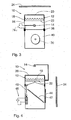
- FIG 2 is a schematic sectional view of the Device 10 according to a first variant with a tubular hollow cylinder 66 shown.
- an actuator 16 is used here a speaker 30, the operational Vibrations over the air on the liquid container 12 are transmitted.
- the hollow cylinder 66 can the loudspeaker box of the loudspeaker 30.
- a cooling tube 32 is located in the tubular hollow cylinder 66 provided in which the light source 14 is arranged approximately in the middle is.
- the cooling tube 32 is open at both ends arranged obliquely upward in the hollow cylinder 66. It has a lower one at one end Air inlet opening 31 and one at its other end higher air outlet opening 33.
- cooling tube 32 Due to the upward arrangement of the cooling tube 32 arises when the light source 14 develops heat upward flow of air, which is also their Cooling causes. This chimney effect makes it cooler Outside air sucked in, and heated air discharged upwards. The density of the air remains in the cooling tube 32 thereby almost the same which in turn remains the same Resonance properties of the transmission medium, namely the air.
- the light source 14 is an adjustable voltage source 36a associated with, for example, their brightness can be varied, i.e. dimmed.
- the transparent one Top 20 of the liquid container 12 can be a mirrors not shown here can be assigned, with which the emerging light effects also against the side existing projection surfaces 24 are thrown can.
- the bottom 22 of the liquid container 12 can also be designed as a transparent membrane his.
- the device 10 Because of the mode of transmission, the device 10 be sealed as airtight as possible.
- the tubular Hollow cylinder 66 itself can be on adjustable feet 34 stand, on the one hand, the desired under certain circumstances Playback function of the speaker 30 to change and improve and on the other hand the mirror the transparent liquid 18 in the liquid container 12 adjust evenly horizontally to be able to.
- the loudspeaker 30 is a controllable voltage source 36 associated, which is part of the schematic in Figure 1 control unit 26 shown. This points an interface to any schematically represented Playback device 28 on. Because of the transfer through air it can make sense if the Control unit 26 a low pass to convert the from signals provided to the playback device 28.
- FIG. 3 Another, simplified version of the device 10 is shown schematically in FIG. 3.
- the frame 56 is on a suitable holder 38 Loudspeaker box 40 fixed.
- the light source 14 is on an adjustable voltage source 36a is connected.
- the Loudspeaker box 40 also serves as an actuator.
- FIG. 4 Another variant of the device 10 is in the figure 4 disclosed.
- Light source 14 is inverted, that is, the light falls from above through the top 20 of the liquid container 12. Then the light is turned on using a Mirror 42 deflected and enters through a side provided window 44 from the device 10 again out.
- An electric drive 46 is used in this embodiment as Actuator 26.
- the electric drive 46 and the liquid container 12 are on the bottom 22 of the Liquid container 12 attached cables 48 together connected. A movement of the electric drive 46 can thus be transferred to the liquid 18.
- the actuator can 26 can also be designed so that it has the side walls of the liquid container 12 vibrated. To do this, he can come into contact with these walls stand and according to one of the control unit 26 vibrate given pattern.
- the liquid container 12 is oscillating Ropes 50 hung.
- the liquid container 12 is assigned a cable 48 which is deflected horizontally attacks laterally.
- the liquid container 12 can thereby be put into a pendulum motion.
- the on this way by periodically actuating the electric drive 46 generated lateral vibrations of the liquid container 12 lead to a movement in this of the liquid 18 and to a corresponding wave pattern.
- This wave image can be generated by means of the light source 14 and the mirror 42 projected onto a wall of a room become.
- FIG. 6 shows an embodiment variant, which essentially consists of. one swinging on ropes 50 suspended liquid container 12 is above a Speaker 30 is suspended. In the radiation area the loudspeaker 30 projects a kind of sail or flag 54, via a boom 52 with the liquid container 12 is connected.
- the loudspeaker 30 If the loudspeaker 30 is in the loudspeaker box 40 moves, this leads to air movements on the sail or hit the flag 54 and so over the Boom 52 lateral to the liquid container 12 Stimulate vibrations.
- This forms on the surface the liquid 18 in the liquid container 12 shows a wave pattern which is based on the one previously described Way by means of the light source 14 and the Mirror 42 can be projected onto the wall of a room can.
- FIG. 7 shows an embodiment in which a continuous membrane 60 integral with the vibration membrane 60a of a loudspeaker 30 is connected.
- the membrane 60 also provides a wall, preferably the bottom, the liquid container 12.
- the membrane 60 is at least in the region of one Aperture 58 transparent and can be from one of them below arranged light source 14 are shined through.
- the one with the membrane 60 of the liquid container 12 integrally connected vibration membrane 60a of the speaker 30 coils 62 are assigned, which are in one Electromagnets 64 are guided.
- the electrical voltage of the Electromagnet 64 changed and the vibration membrane 60a excited.
Applications Claiming Priority (2)
| Application Number | Priority Date | Filing Date | Title |
|---|---|---|---|
| DE10114048A DE10114048A1 (de) | 2001-03-15 | 2001-03-15 | Vorrichtung zur Erzeugung eines Lichteffektes |
| DE10114048 | 2001-03-15 |
Publications (2)
| Publication Number | Publication Date |
|---|---|
| EP1240927A2 true EP1240927A2 (de) | 2002-09-18 |
| EP1240927A3 EP1240927A3 (de) | 2005-04-06 |
Family
ID=7678567
Family Applications (1)
| Application Number | Title | Priority Date | Filing Date |
|---|---|---|---|
| EP02090110A Withdrawn EP1240927A3 (de) | 2001-03-15 | 2002-03-15 | Vorrichtung zur Erzeugung von Lichteffekten |
Country Status (3)
| Country | Link |
|---|---|
| US (1) | US6612935B2 (nl) |
| EP (1) | EP1240927A3 (nl) |
| DE (1) | DE10114048A1 (nl) |
Families Citing this family (8)
| Publication number | Priority date | Publication date | Assignee | Title |
|---|---|---|---|---|
| GB0410235D0 (en) * | 2004-05-10 | 2004-06-09 | Vardy Alastair | A lighting apparatus |
| WO2009104122A1 (en) * | 2008-02-21 | 2009-08-27 | Philips Intellectual Property & Standards Gmbh | Projection device |
| WO2010007568A1 (en) * | 2008-07-17 | 2010-01-21 | Koninklijke Philips Electronics N.V. | Optical element for inducing a variation of light from a light source |
| KR20100021848A (ko) * | 2008-08-18 | 2010-02-26 | 삼성전자주식회사 | 표시 장치용 노광 장치 및 노광 방법 |
| JP2011223397A (ja) * | 2010-04-12 | 2011-11-04 | Sony Corp | スピーカ装置 |
| US9272225B2 (en) * | 2011-09-13 | 2016-03-01 | Kids Ii, Inc. | Crib soother |
| DE102014103409A1 (de) * | 2014-03-13 | 2015-11-26 | Magicfloor Ag | Beleuchtungseinrichtung |
| DE102015014012A1 (de) * | 2015-10-30 | 2017-05-04 | Durdica Müller | Leuchtmittel |
Citations (2)
| Publication number | Priority date | Publication date | Assignee | Title |
|---|---|---|---|---|
| WO1988005685A1 (en) | 1987-02-02 | 1988-08-11 | Stastny U. Schrögendorfer Gesellschaft M.B.H. | Device for producing light effects |
| DE3922661A1 (de) | 1989-07-10 | 1991-01-24 | Peter Bernhard | Lichtkinetisches objekt |
Family Cites Families (15)
| Publication number | Priority date | Publication date | Assignee | Title |
|---|---|---|---|---|
| DE2415285A1 (de) * | 1974-03-29 | 1975-10-09 | Guenther Kaminski Fa | Vorrichtung zur erzeugung von lichteffekten |
| DE2801354A1 (de) * | 1978-01-13 | 1979-08-02 | Bernd Zimmermann | Dynamische fluessigkeits-lichtorgel |
| US4232304A (en) * | 1979-06-11 | 1980-11-04 | Durley Iii Benton A | Vibratory-rotary motion converters and display devices incorporating such converters |
| US4985811A (en) * | 1990-04-05 | 1991-01-15 | Weiner Mark W | Aqua light |
| DE9311678U1 (de) * | 1993-08-05 | 1993-12-16 | Arbeitsfoerderung Beschaeftigu | Wassergefülltes, beleuchtetes Dekorationsglas |
| DE4440583C2 (de) * | 1994-11-14 | 2002-02-28 | Albert Baur | Lautsprecher-Leuchten-Kombination |
| IT1277518B1 (it) * | 1995-08-31 | 1997-11-10 | Helmut Eigenmann | Metodo per la realizzazione di effetti scenografici e decorativi mediante la proiezione luminosa di onde di liquido |
| JPH10134609A (ja) * | 1996-10-30 | 1998-05-22 | Tokyo Aqua Art:Kk | 変化する照明効果を有する装飾体 |
| DE19758095A1 (de) * | 1997-12-18 | 1999-06-24 | Ulrich Roskopf | Vorrichtung für die Erzeugung frequenzabhängiger Lichteffekte |
| US5916030A (en) * | 1998-03-24 | 1999-06-29 | Warner; Gregory K. | Circulating water sound box |
| DE29901468U1 (de) * | 1999-01-29 | 1999-05-06 | Strobl Matthias | Dekorativer Deckenfluter |
| CA2262338C (en) * | 1999-02-19 | 2005-09-13 | Dimplex North America Limited | Simulated fireplace assembly |
| US6168531B1 (en) * | 1999-06-15 | 2001-01-02 | Sony Corporation | Soup bowl attraction |
| US6135604A (en) * | 1999-10-25 | 2000-10-24 | Lin; Kuo Jung | Decorative water lamp |
| US6270420B1 (en) * | 2000-01-28 | 2001-08-07 | Vincent K. Lee | Ornamental liquid container producing dynamic views |
-
2001
- 2001-03-15 DE DE10114048A patent/DE10114048A1/de not_active Withdrawn
-
2002
- 2002-03-15 EP EP02090110A patent/EP1240927A3/de not_active Withdrawn
- 2002-03-15 US US10/097,569 patent/US6612935B2/en not_active Expired - Fee Related
Patent Citations (2)
| Publication number | Priority date | Publication date | Assignee | Title |
|---|---|---|---|---|
| WO1988005685A1 (en) | 1987-02-02 | 1988-08-11 | Stastny U. Schrögendorfer Gesellschaft M.B.H. | Device for producing light effects |
| DE3922661A1 (de) | 1989-07-10 | 1991-01-24 | Peter Bernhard | Lichtkinetisches objekt |
Also Published As
| Publication number | Publication date |
|---|---|
| US20030027643A1 (en) | 2003-02-06 |
| DE10114048A1 (de) | 2002-10-02 |
| EP1240927A3 (de) | 2005-04-06 |
| US6612935B2 (en) | 2003-09-02 |
Similar Documents
| Publication | Publication Date | Title |
|---|---|---|
| DE3038939C2 (nl) | ||
| US6978030B2 (en) | Light emitting loudspeaker cover | |
| US20090046258A1 (en) | Video display system with an oscillating projector screen | |
| DE202014100821U1 (de) | Ein Simulationsgerät von Kerzenflamme | |
| EP1240927A2 (de) | Vorrichtung zur Erzeugung von Lichteffekten | |
| EP1506691B1 (de) | Lautsprecher | |
| DE112010000671T5 (de) | Schallerzeugungssystem, Schallaufzeichnungssystem, Schallerzeugungsverfahren, Schallaufzeichnungsverfahren, Schalleinstellverfahren, Schalleinstellprogramm, Schallfeldeinstellsystem, Lautsprecherständer, Möbel, Lautsprechergehäuse und Lautsprechervorrichtung | |
| EP0434754A1 (de) | Vorrichtung zur schallabstrahlung und musikinstrument | |
| WO2010130676A1 (de) | Lautsprechervorrichtung | |
| DE1959101A1 (de) | Audio-visuelle Anlage | |
| US3603195A (en) | Music-responsive light display | |
| DE2814268A1 (de) | Unterhaltungsvorrichtung mit einer lichtabstrahlenden waffe | |
| DE102006056394B4 (de) | Beleuchtungseinrichtung | |
| WO2003041573A1 (de) | Beleuchtungseinheit zur erzeugung von optischen schnittbildern in transparenten medien, insbesondere im auge | |
| WO2012072622A1 (de) | Lautsprechervorrichtung | |
| CN108413343A (zh) | 减小来自具有步进马达的灯具的声音的方法 | |
| DE4440583C2 (de) | Lautsprecher-Leuchten-Kombination | |
| EP0346324B1 (de) | Vorrichtung zur erzeugung von lichteffekten | |
| US20070113656A1 (en) | Acoustic imaging system | |
| AT519468A4 (de) | Stimmvorrichtung einer Pfeife einer Orgel | |
| DE3831187A1 (de) | Vorrichtung zur schallabstrahlung mittels eines plattenfoermigen, elektro-dynamisch angeregten klangkoerpers | |
| DE102009043661B4 (de) | Vorrichtung zur Visualisierung von Biegewellen-Schwingungen bei Schallgebern auf Biegewellenbasis | |
| US3473429A (en) | Sound to color transducer | |
| CA2259239A1 (en) | Kaleidoscope | |
| DE102021121947B3 (de) | Vorrichtung, System und Verfahren zur Erzeugung beweglicher räumlicher visueller Effekte mittels Laserlicht |
Legal Events
| Date | Code | Title | Description |
|---|---|---|---|
| PUAI | Public reference made under article 153(3) epc to a published international application that has entered the european phase |
Free format text: ORIGINAL CODE: 0009012 |
|
| AK | Designated contracting states |
Kind code of ref document: A2 Designated state(s): AT BE CH CY DE DK ES FI FR GB GR IE IT LI LU MC NL PT SE TR |
|
| AX | Request for extension of the european patent |
Free format text: AL;LT;LV;MK;RO;SI |
|
| PUAL | Search report despatched |
Free format text: ORIGINAL CODE: 0009013 |
|
| AK | Designated contracting states |
Kind code of ref document: A3 Designated state(s): AT BE CH CY DE DK ES FI FR GB GR IE IT LI LU MC NL PT SE TR |
|
| AX | Request for extension of the european patent |
Extension state: AL LT LV MK RO SI |
|
| AKX | Designation fees paid | ||
| REG | Reference to a national code |
Ref country code: DE Ref legal event code: 8566 |
|
| STAA | Information on the status of an ep patent application or granted ep patent |
Free format text: STATUS: THE APPLICATION IS DEEMED TO BE WITHDRAWN |
|
| 18D | Application deemed to be withdrawn |
Effective date: 20051007 |