EP1247894A2 - Press and suction element - Google Patents
Press and suction element Download PDFInfo
- Publication number
- EP1247894A2 EP1247894A2 EP02007027A EP02007027A EP1247894A2 EP 1247894 A2 EP1247894 A2 EP 1247894A2 EP 02007027 A EP02007027 A EP 02007027A EP 02007027 A EP02007027 A EP 02007027A EP 1247894 A2 EP1247894 A2 EP 1247894A2
- Authority
- EP
- European Patent Office
- Prior art keywords
- suction
- press
- fibrous web
- suction element
- stationary
- Prior art date
- Legal status (The legal status is an assumption and is not a legal conclusion. Google has not performed a legal analysis and makes no representation as to the accuracy of the status listed.)
- Granted
Links
Images

Classifications
-
- D—TEXTILES; PAPER
- D21—PAPER-MAKING; PRODUCTION OF CELLULOSE
- D21F—PAPER-MAKING MACHINES; METHODS OF PRODUCING PAPER THEREON
- D21F3/00—Press section of machines for making continuous webs of paper
- D21F3/02—Wet presses
- D21F3/04—Arrangements thereof
- D21F3/045—Arrangements thereof including at least one extended press nip
-
- D—TEXTILES; PAPER
- D21—PAPER-MAKING; PRODUCTION OF CELLULOSE
- D21F—PAPER-MAKING MACHINES; METHODS OF PRODUCING PAPER THEREON
- D21F3/00—Press section of machines for making continuous webs of paper
- D21F3/02—Wet presses
- D21F3/0272—Wet presses in combination with suction or blowing devices
Definitions
- the invention relates to a press arrangement for draining a paper, cardboard, tissue or other Fibrous web in a machine for producing the same with at least a press nip formed by two press rolls through which next a press felt runs on both sides of the fibrous web.
- a second Aspect relates to a stationary suction element which in the preamble of Claim 11 Art.
- a press arrangement of the type mentioned is, for example, in the US 5 951 821.
- Suction elements of the type mentioned result, for example, from the publications US 5 885 421, DE-C-41 02 065, EP-A-0 405 154, DE-C-195 11 988 and DE-A-27 16 583.
- the first aspect of the invention teaches in particular high web speeds leading away the upper press felt from problems with the fibrous web after the press nip. Is critical especially the edge area of the fibrous web. The edge often comes loose not immediately from the upper press felt, so that it plucked so-called comes. As a result, there are tears or even tears in the fibrous web not uncommon.
- the object was achieved in that after Press nip both press felts together with the fiber web a guide roller partially loop around the lower press felt and form one with the suction press in contact with the lower press felt, whereby the upper press felt in the area of the suction box from the fibrous web is led away.
- the deflection on the guide roller makes it easy Detachment of the upper press felt from the fibrous web - especially if the guide roller is vacuumed. The vacuum coming from the suction box then enables the upper press felt to be easily removed the fibrous web.
- the negative pressure of the guide roller and the suction box acts through the through the lower press felt and thus increases the adhesion of the fibrous web on the lower press felt.
- the upper press felt is advantageous already in the beginning of the suction box from the fibrous web led away.
- the contact surface should of the suction box at least in one, preferably at the beginning Section be convexly curved towards the lower press felt. It can however, it may also be advantageous if all or at least the majority Part of the contact surface of the suction box is convex to the lower one Press felt is curved.
- a special configuration results if the contact surface of the suction box in a preferably at the beginning lying section has a stronger, convex curvature than in the remaining part.
- the device according to the invention allows the upper press felt in Lead area of the first suction slot away from the fibrous web, see above that in the further course of the suction box the adhesion of the fibrous web can be increased on the lower press felt.
- the suction box should be in the area of the edges of the fibrous web each have a separate vacuum zone with increased negative pressure.
- the invention relates to a stationary suction element for sucking up a paper, cardboard, tissue or other Fibrous web on an air-permeable, endlessly running belt Machine for the production and / or finishing of the fibrous web, wherein the tape slides over a contact surface of the suction element and the Contact surface has several suction openings and use.
- suction elements are also known as suction boxes with a substantially flat contact surface.
- the Adhesion of the fibrous web often used vacuumed rollers. Due to the limited open surface (suction openings) of a vacuumed roller, which is between 20 and 60%, the fibrous web is mainly at high speeds insufficiently fixed to the belt, making it can come off the web and flutter.
- Another object of the invention is therefore with as little as possible Effort, the adhesion of the fibrous web to the belt during a belt deflection to improve.
- this object has been achieved in that the contact surface runs convexly curved in the direction of web travel.
- the curved one The contact surface is immersed in the belt and enables such a relatively long, vacuumed route.
- the fibrous web adheres very well to the belt itself at high speeds and despite the belt deflection. This also applies to the edges of the fibrous web.
- Suction elements whose contact surface in the web running direction are particularly suitable is curved in the shape of a sector of a circle, the radius of curvature are in the range of 0.2 to 10 m, preferably between 0.4 and 3 m should. However, other forms of curvature are also possible.
- the suction openings should be designed as suction slots.
- suction slots are oblique to the web running direction run.
- the oblique arrangement looks like a suction the tape into the suction slots.
- suction slots it is also possible for the suction slots to be approximately transverse to the web running direction run.
- the suction element several, preferably transversely to the web running direction extending and arranged side by side in the web running direction Has suction zones, at least that of the suction openings outgoing vacuum of each suction zone is independently adjustable. there it is often sufficient if the suction element has two suction zones. For certain application it can limit energy for negative pressure generation as well as the volume caused by the air flow, be advantageous if the suction element at least, preferably has exactly three suction zones.
- Suction opening outgoing negative pressure is separately adjustable. This applies especially if at least one, preferably all Suction zones are formed by one suction opening each. However, can also the suction openings of a suction zone, if it has several, individually be adjustable.
- the desired extension of the suction zones in the direction of web travel may require at least one, preferably all Suction zones are formed by several suction openings, the Suction openings of a suction zone with each other via a suction chamber are connected and the vacuum in the suction chambers separately is adjustable.
- the level of the negative pressure of each suction zone cannot only manually adjustable, but also independently controllable become.
- the controllability allows adjustments to the web speed, the type of fibrous web, its weight, moisture content, etc.
- the suction element can preferably be humidified at the beginning assigned to moisten the contact surface. Suitable for this purpose are, for example, transverse to the web running direction Sprays. For versions with many suction openings there is also one Humidification possible from the inside of the suction element.
- the stationary suction element is particularly suitable for use with which the fibrous web in front of the suction element from both sides one Band guided and that with respect to the suction element outer band in Area of the suction element is guided away from the fibrous web.
- the Curvature of the contact surface allows a relatively large opening angle between the bands, what the ventilation of the gusset improved. As a result, the risk of edge fluttering decreases Fibrous web.
- the opening angle should preferably be greater than 10 ° his.
- the outer band When using the suction element, the outer band should be in the direction of web travel viewed in the middle of the contact area of the fibrous web are led away. It is particularly advantageous if the outer band in the area of the second suction zone from the fibrous web is led away, the suction element preferably three suction zones having.
- the first suction zone serves to pre-fix the fibrous web on the belt, the second of fixing the fibrous web during the Removal of the outer ligament and the third fixation. All Suction zones have different requirements due to their function to the level of negative pressure, so that via the separate control the level of negative pressure, the noise and the energy for Vacuum generation can be minimized.
- Suitable applications arise where at least the tape running between the fibrous web and the suction element as Press felt of a press section designed for dewatering the fibrous web is.
- the use is particularly advantageous where the tapes with the fibrous web from a press nip of the press section to Arrive suction element, wherein the press nip preferably extends should be executed.
- Figure 1 shows a cross section of an exemplary embodiment a press assembly according to the first aspect of the invention.
- the fibrous web 1 runs through on both sides with a press felt 4.5 a press nip formed by two press rolls 2, 3. While the lower one Press roll 3 is cylindrical, the upper press roll 2 a flexible roll shell, which forms an extended press nip runs over a pressure shoe with a concave pressure surface. Naturally is a reversal of this press roll arrangement, that is upper cylindrical press roll 3 also possible.
- Press felts 4, 5 take this from the fibrous web 1 in the press nip pressed water. That via the press felts 4, 5 to the press rolls 2, 3 Any water that enters is thrown off by these after the press nip and taken up by suitable, known water collecting device 12.
- the fibrous web 1 runs together with both Press felts 4, 5 via a suction guide roller 6 of the lower press felt 5.
- This guide roller 6 has a perforated roller shell, the interior is connected to a vacuum source. This negative pressure works through the lower press felt 5 onto the fibrous web 1 and thus reinforced the adhesion of the fibrous web 1 to the lower press felt 5.
- Suction box 7 has a convex curve towards the lower press felt 5 Contact area.
- the delimitation of that associated with a vacuum source Interior of the suction box 7 opposite the lower press felt 5 is by the formation of several, transverse to the web running direction 8th extending suction slots 9 guaranteed in the contact surface.
- the negative pressure of the suction box 7 increases Adhesion of the entire fibrous web 1 to the lower press felt 5, so that already in the area of the first suction slot 9 of the suction box 7 the upper one Press felt 4 can be guided away from the fibrous web 1.
- the fibrous web 1 is then attached to a belt 10, for example a Hand over dryer fabric to a subsequent dryer section of the paper machine, which is supported by a suction guide roller 11.
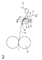
- Figure 2 shows a schematic cross section of an exemplary Embodiment of a suction element 23 according to the second aspect the invention.
- the fibrous web 21 runs together with a belt on both sides 22, 30 an extended press nip formed by two press rollers 32. This serves to dewater the fibrous web 21, the belts 22, 30 designed as water-absorbing and air-permeable press felts are.
- the press nip is part of a press section of a paper machine for manufacture the fibrous web 21.
- the fibrous web 21 is removed from the press nip by both belts 22, 30 led to the suction element 23.
- the middle area of the suction element 23 is that, with respect to the suction element 23 outer band 30 from the fibrous web 21 led away.
- the inner band 22 guides the fibrous web 21 to a subsequent unit, the fibrous web 21 for example from a press felt of a subsequent press nip or one Dryer screen of a following dryer section can be taken over.
- the suction element 23 has a contact area curved in the shape of a sector of a circle 24 over which the inner band 22 slides.
- the radius of curvature this convex curvature is approximately 1 m.
- the suction element 23 has three suction zones 27, each of which has a suction opening 25 in the form of a suction slot running transversely to the web running direction 26 are formed in the contact surface 24.
- the suction openings 25 are each connected to a vacuum source via a suction chamber, the level of vacuum of each suction chamber 34 independent is controllable via a valve 33.
- the negative pressure emanating from the suction openings 25 can thus be applied to the local requirements are adjusted and minimized in height what not only saves energy, but also reduces the noise of the air flow.
- first suction opening 25 or suction zone 27 serves the Adhesion of the fibrous web 21 to the inner band 22 to increase through the second suction zone 27 a lifting of the fibrous web 21, in particular of its edges, from the inner band 22 during the removal of the outer band 30 can be prevented. Therefore requires the second suction zones 27 an increased negative pressure.
- the last suction zone 27 in the direction of web travel 26 is only intended to again Strengthen the adhesion of the fibrous web 21 to the inner band 22 and requires it therefore usually a lower negative pressure.
- the opening angle is 31 between Fibrous web 21 and the outer band 30 about 20 °.
- the contact surface 24 of the suction element 23 is essentially of Ledges 29 extending transversely to the web running direction 26 are formed. This Last 29 are adapted to the tape run and limit the individual Suction openings 25, that is, the suction slots.
- the strips 29 have a ceramic layer on the surface guiding the strip 22.
Abstract
Description
Die Erfindung betrifft gemäß einem ersten Aspekt eine Pressanordnung
zur Entwässerung einer Papier-, Karton-, Tissue- oder einer anderen
Faserstoffbahn in einer Maschine zur Herstellung derselben mit zumindest
einem, von zwei Presswalzen gebildeten Pressspalt, durch den neben
der Faserstoffbahn beidseitig je ein Pressfilz läuft. Gemäß einem zweiten
Aspekt betrifft sie ein stationäres Saugelement der im Oberbegriff des
Anspruchs 11 genannten Art.According to a first aspect, the invention relates to a press arrangement
for draining a paper, cardboard, tissue or other
Fibrous web in a machine for producing the same with at least
a press nip formed by two press rolls through which next
a press felt runs on both sides of the fibrous web. According to a second
Aspect relates to a stationary suction element which in the preamble of
Eine Pressanordnung der eingangs genannten Art ist beispielsweise in der US 5 951 821 beschrieben. Saugelemente der eingangs genannten Art ergeben sich beispielsweise aus den Druckschriften US 5 885 421, DE-C-41 02 065, EP-A-0 405 154, DE-C-195 11 988 und DE-A-27 16 583.A press arrangement of the type mentioned is, for example, in the US 5 951 821. Suction elements of the type mentioned result, for example, from the publications US 5 885 421, DE-C-41 02 065, EP-A-0 405 154, DE-C-195 11 988 and DE-A-27 16 583.
Was den ersten Aspekt der Erfindung betrifft, so bringt insbesondere bei hohen Bahngeschwindigkeiten das Wegführen des oberen Pressfilzes von der Faserstoffbahn nach dem Pressspalt Probleme mit sich. Kritisch ist vor allem der Randbereich der Faserstoffbahn. Häufig löst sich der Rand nicht sofort vom oberen Pressfilz, so dass es zum so genannten Randzupfen kommt. In der Folge sind Einrisse oder sogar Abrisse der Faserstoffbahn nicht ungewöhnlich.As for the first aspect of the invention, teaches in particular high web speeds leading away the upper press felt from problems with the fibrous web after the press nip. Is critical especially the edge area of the fibrous web. The edge often comes loose not immediately from the upper press felt, so that it plucked so-called comes. As a result, there are tears or even tears in the fibrous web not uncommon.
Eine Aufgabe der Erfindung ist es daher, eine sichere Führung der Faserstoffbahn beim und nach dem Wegführen des oberen Pressfilzes zu gewährleisten. It is therefore an object of the invention to reliably guide the fibrous web to ensure during and after the removal of the upper press felt.
Erfindungsgemäß wurde die Aufgabe dadurch gelöst, dass nach dem Pressspalt beide Pressfilze gemeinsam mit der Faserstoffbahn eine Leitwalze des unteren Pressfilzes teilweise umschlingen und zu einem, mit dem unteren Pressfilz in Kontakt stehenden Saugkasten laufen, wobei der obere Pressfilz im Bereich des Saugkastens von der Faserstoffbahn weggeführt wird. Die Umlenkung an der Leitwalze bewirkt ein leichtes Ablösen des oberen Pressfilzes von der Faserstoffbahn - erst recht, wenn die Leitwalze besaugt ist. Der vom Saugkasten ausgehende Unterdruck ermöglicht dann ein problemloses Wegführen des oberen Pressfilzes von der Faserstoffbahn.According to the invention the object was achieved in that after Press nip both press felts together with the fiber web a guide roller partially loop around the lower press felt and form one with the suction press in contact with the lower press felt, whereby the upper press felt in the area of the suction box from the fibrous web is led away. The deflection on the guide roller makes it easy Detachment of the upper press felt from the fibrous web - especially if the guide roller is vacuumed. The vacuum coming from the suction box then enables the upper press felt to be easily removed the fibrous web.
Der Unterdruck der Leitwalze sowie des Saugkastens wirkt durch den unteren Pressfilz hindurch und verstärkt so die Haftung der Faserstoffbahn am unteren Pressfilz. Mit Vorteil wird dabei der obere Pressfilz bereits im Anfangsbereich des Saugkastens von der Faserstoffbahn weggeführt.The negative pressure of the guide roller and the suction box acts through the through the lower press felt and thus increases the adhesion of the fibrous web on the lower press felt. The upper press felt is advantageous already in the beginning of the suction box from the fibrous web led away.
Um den Lauf des unteren Pressfilzes zu stabilisieren, sollte die Kontaktfläche des Saugkastens zumindest in einem, vorzugsweise am Beginn liegenden Abschnitt zum unteren Pressfilz hin konvex gekrümmt sein. Es kann jedoch auch vorteilhaft sein, wenn das gesamte oder wenigstens der überwiegende Teil der Kontaktfläche des Saugkastens konvex zum unteren Pressfilz hin gekrümmt ist. Eine spezielle Ausgestaltung ergibt sich dabei, wenn die Kontaktfläche des Saugkastens in einem vorzugsweise am Beginn liegenden Abschnitt eine stärkere, konvexe Krümmung aufweist als im übrigen Teil. Vorteile hinsichtlich der Führung der Faserstoffbahn sind zu verzeichnen, wenn der obere Pressfilz im Bereich des überhaupt oder am stärksten konvex gekrümmten Abschnittes der Kontaktfläche von der Faserstoffbahn weggeführt wird. In order to stabilize the run of the lower press felt, the contact surface should of the suction box at least in one, preferably at the beginning Section be convexly curved towards the lower press felt. It can however, it may also be advantageous if all or at least the majority Part of the contact surface of the suction box is convex to the lower one Press felt is curved. A special configuration results if the contact surface of the suction box in a preferably at the beginning lying section has a stronger, convex curvature than in the remaining part. There are advantages with regard to the guidance of the fibrous web to be recorded if the upper press felt in the area of at all or most convexly curved portion of the contact surface from the Fiber web is led away.
Zur Gewährleistung der Begrenzung des mit einer Unterdruckquelle in Verbindung stehenden Innenraumes des Saugkastens besitzt dieser mehrere, etwa quer zur Bahnlaufrichtung verlaufende Saugschlitze.To ensure the limitation of using a vacuum source in Connected interior of the suction box has this several suction slits running approximately perpendicular to the web running direction.
Die erfindungsgemäße Vorrichtung erlaubt es, den oberen Pressfilz im Bereich des ersten Saugschlitzes von der Faserstoffbahn wegzuführen, so dass im weiteren Verlauf des Saugkastens die Haftung der Faserstoffbahn am unteren Pressfilz noch gesteigert werden kann.The device according to the invention allows the upper press felt in Lead area of the first suction slot away from the fibrous web, see above that in the further course of the suction box the adhesion of the fibrous web can be increased on the lower press felt.
Um dem Randflattern und Randzupfen der Faserstoffbahn zu begegnen, sollte der Saugkasten im Bereich der Ränder der Faserstoffbahn jeweils eine separate Vakuumzone mit erhöhtem Unterdruck besitzen.To counter the fluttering and plucking of the fibrous web, the suction box should be in the area of the edges of the fibrous web each have a separate vacuum zone with increased negative pressure.
Gemäß dem zweiten Aspekt betrifft die Erfindung ein stationäres Saugelement zum Ansaugen einer Papier-, Karton-, Tissue- oder einer anderen Faserstoffbahn an ein luftdurchlässiges, endlos um laufendes Band einer Maschine zur Herstellung und/oder Veredelung der Faserstoffbahn, wobei das Band über eine Kontaktfläche des Saugelementes gleitet und die Kontaktfläche mehrere Saugöffnungen besitzt sowie der Verwendung.According to the second aspect, the invention relates to a stationary suction element for sucking up a paper, cardboard, tissue or other Fibrous web on an air-permeable, endlessly running belt Machine for the production and / or finishing of the fibrous web, wherein the tape slides over a contact surface of the suction element and the Contact surface has several suction openings and use.
Saugelemente sind neben der Ausführung als rotierende Saugwalzen auch als Saugkästen mit im wesentlichen ebener Kontaktfläche bekannt.In addition to the design as rotating suction rolls, suction elements are also known as suction boxes with a substantially flat contact surface.
Bei notwendigen Bandumlenkungen werden zur Gewährleistung der Haftung der Faserstoffbahn oft besaugte Walzen eingesetzt. Aufgrund der begrenzten offenen Oberfläche (Saugöffnungen) einer besaugten Walze, die zwischen 20 und 60 % liegt, wird die Faserstoffbahn vor allem bei hohen Geschwindigkeiten nur unzureichend am Band fixiert, so dass es zum Bahnabheben und zum Randflattern kommen kann. If belt deflections are necessary, the Adhesion of the fibrous web often used vacuumed rollers. Due to the limited open surface (suction openings) of a vacuumed roller, which is between 20 and 60%, the fibrous web is mainly at high speeds insufficiently fixed to the belt, making it can come off the web and flutter.
Eine weitere Aufgabe der Erfindung ist es daher, mit möglichst geringem Aufwand, die Haftung der Faserstoffbahn am Band bei einer Bandumlenkung zu verbessern.Another object of the invention is therefore with as little as possible Effort, the adhesion of the fibrous web to the belt during a belt deflection to improve.
Erfindungsgemäß wurde diese Aufgabe dadurch gelöst, dass die Kontaktfläche in Bahnlaufrichtung konvex gekrümmt verläuft. Die gekrümmte Kontaktfläche taucht dabei in den Lauf des Bandes ein und ermöglicht so eine relativ lange, besaugte Strecke. Auch kann wegen des stationären Einbaus die offene Fläche, das heißt die Summe der Saugöffnungen bezogen auf die Kontaktfläche relativ groß gewählt werden. Im Ergebnis kommt es zu einer sehr guten Haftung der Faserstoffbahn am Bandselbst bei hohen Geschwindigkeiten und trotz der Bandumlenkung. Dies gilt auch für die Ränder der Faserstoffbahn.According to the invention, this object has been achieved in that the contact surface runs convexly curved in the direction of web travel. The curved one The contact surface is immersed in the belt and enables such a relatively long, vacuumed route. Can also because of the stationary Installation of the open area, i.e. the sum of the suction openings based on the contact area can be chosen to be relatively large. As a result the fibrous web adheres very well to the belt itself at high speeds and despite the belt deflection. This also applies to the edges of the fibrous web.
Besonders geeignet sind Saugelemente deren Kontaktfläche in Bahnlaufrichtung kreissektorförmig gekrümmt ist, wobei der Krümmungsradius im Bereich von 0,2 bis 10 m, vorzugsweise zwischen 0,4 und 3 m liegen sollte. Es sind jedoch auch andere Krümmungsformen möglich.Suction elements whose contact surface in the web running direction are particularly suitable is curved in the shape of a sector of a circle, the radius of curvature are in the range of 0.2 to 10 m, preferably between 0.4 and 3 m should. However, other forms of curvature are also possible.
Im Interesse einer einfachen Herstellbarkeit sowie einer großen offenen Fläche sollten die Saugöffnungen als Saugschlitze ausgebildet sein. Hierbei besteht die Möglichkeit, dass die Saugschlitze schräg zur Bahnlaufrichtung verlaufen. Die schräge Anordnung wirkt einem Einsaugen des Bandes in die Saugschlitze entgegen.In the interest of easy manufacture and a large open one Surface, the suction openings should be designed as suction slots. There is the possibility that the suction slots are oblique to the web running direction run. The oblique arrangement looks like a suction the tape into the suction slots.
Es ist jedoch auch möglich, dass die Saugschlitze etwa quer zur Bahnlaufrichtung verlaufen.However, it is also possible for the suction slots to be approximately transverse to the web running direction run.
Zur Anpassung an die örtlich notwendige Unterdruckhöhe ist es vorteilhaft, wenn das Saugelement mehrere, sich vorzugsweise quer zur Bahnlaufrichtung erstreckende und in Bahnlaufrichtung nebeneinander angeordnete Saugzonen besitzt, wobei zumindest der, von den Saugöffnungen ausgehende Unterdruck jeder Saugzone unabhängig einstellbar ist. Dabei ist es oft ausreichend, wenn das Saugelement zwei Saugzonen besitzt. Für bestimmte Anwendung kann es zur Begrenzung der Energie zur Unterdruckerzeugung sowie der Lautstärke, durch die Luftströmung verursacht, von Vorteil sein, wenn das Saugelement mindestens, vorzugsweise genau drei Saugzonen besitzt.To adapt to the locally required vacuum level, it is advantageous if the suction element several, preferably transversely to the web running direction extending and arranged side by side in the web running direction Has suction zones, at least that of the suction openings outgoing vacuum of each suction zone is independently adjustable. there it is often sufficient if the suction element has two suction zones. For certain application it can limit energy for negative pressure generation as well as the volume caused by the air flow, be advantageous if the suction element at least, preferably has exactly three suction zones.
Je nach Anwendung kann es auch vorteilhaft sein, wenn der, von jeder Saugöffnung ausgehende Unterdruck separat einstellbar ist. Dies gilt natürlich insbesondere dann, wenn zumindest eine, vorzugsweise alle Saugzonen von jeweils einer Saugöffnung gebildet werden. Jedoch können auch die Saugöffnungen einer Saugzone, sofern sie mehrere besitzt, einzeln einstellbar sein.Depending on the application, it can also be advantageous if that of everyone Suction opening outgoing negative pressure is separately adjustable. this applies Of course, especially if at least one, preferably all Suction zones are formed by one suction opening each. However, can also the suction openings of a suction zone, if it has several, individually be adjustable.
Vor allem die gewünschte Ausdehnung der Saugzonen in Bahnlaufrichtung kann es erforderlich machen, dass zumindest eine, vorzugsweise alle Saugzonen von mehreren Saugöffnungen gebildet werden, wobei die Saugöffnungen einer Saugzone jeweils über eine Saugkammer miteinander verbunden sind und der Unterdruck in den Saugkammern separat einstellbar ist.Above all, the desired extension of the suction zones in the direction of web travel may require at least one, preferably all Suction zones are formed by several suction openings, the Suction openings of a suction zone with each other via a suction chamber are connected and the vacuum in the suction chambers separately is adjustable.
Allgemein betrachtet kann die Höhe des Unterdrucks jeder Saugzone nicht nur manuell einstellbar, sondern auch unabhängig steuerbar gestaltet werden. Die Steuerbarkeit erlaubt Anpassungen an die Bahngeschwindigkeit, die Art der Faserstoffbahn, deren Gewicht, Feuchtegehalt usw..Generally speaking, the level of the negative pressure of each suction zone cannot only manually adjustable, but also independently controllable become. The controllability allows adjustments to the web speed, the type of fibrous web, its weight, moisture content, etc.
Zur Verringerung der Reibung zwischen dem Band und der Kontaktfläche sollte diese zumindest teilweise aus Keramik bestehen. Aus demselben Grund kann dem Saugelement vorzugsweise am Beginn eine Befeuchtungseinrichtung zur Befeuchtung der Kontaktfläche zugeordnet werden. Hierzu eignen sich beispielsweise quer zur Bahnlaufrichtung verlaufende Spritzrohre. Bei Ausführungen mit vielen Saugöffnungen ist auch eine Befeuchtung, vom Inneren des Saugelementes ausgehend, möglich.To reduce the friction between the belt and the contact surface should at least partially consist of ceramic. From the same The suction element can preferably be humidified at the beginning assigned to moisten the contact surface. Suitable for this purpose are, for example, transverse to the web running direction Sprays. For versions with many suction openings there is also one Humidification possible from the inside of the suction element.
Vorteil hinsichtlich Herstellbarkeit und offener Fläche ergeben sich, wenn die Kontaktfläche von mehreren, etwa quer zur Bahnlaufrichtung verlaufenden Leisten gebildet wird. Die Form der Leisten sollte sich dabei dem Verlauf des Bandes anpassen.There is an advantage in terms of manufacturability and open area if the contact surface of several, approximately transverse to the web running direction Last is formed. The shape of the last should be the same Adjust the course of the tape.
Besonders geeignet ist das stationäre Saugelement für Verwendungen bei denen die Faserstoffbahn vor dem Saugelement von beidseitig je einem Band geführt und dass bezüglich des Saugelementes äußere Band im Bereich des Saugelementes von der Faserstoffbahn weggeführt wird. Die Krümmung der Kontaktfläche erlaubt dabei einen relativ großen Öffnungswinkel zwischen den Bändern, was die Belüftung des Zwickels verbessert. Infolgedessen verringert sich die Gefahr des Randflatterns der Faserstoffbahn. Vorzugsweise sollte der Öffnungswinkel größer als 10° sein.The stationary suction element is particularly suitable for use with which the fibrous web in front of the suction element from both sides one Band guided and that with respect to the suction element outer band in Area of the suction element is guided away from the fibrous web. The Curvature of the contact surface allows a relatively large opening angle between the bands, what the ventilation of the gusset improved. As a result, the risk of edge fluttering decreases Fibrous web. The opening angle should preferably be greater than 10 ° his.
Bei der Verwendung des Saugelementes sollte das äußere Band in Bahnlaufrichtung betrachtet etwa im mittleren Bereich der Kontaktfläche von der Faserstoffbahn weggeführt werden. Besonders vorteilhaft ist es, wenn das äußere Band im Bereich der zweiten Saugzone von der Faserstoffbahn weggeführt wird, wobei das Saugelement vorzugsweise drei Saugzonen aufweist. Dabei dient die erste Saugzonen der Vorfixierung der Faserstoffbahn am Band, die zweite der Fixierung der Faserstoffbahn während des Wegführens des äußeren Bandes und die dritte der Nachfixierung. Alle Saugzonen haben bedingt durch ihre Funktion verschiedene Anforderungen an die Höhe des Unterdrucks, so dass über die separate Steuerung der Höhe des Unterdrucks die Lärmentwicklung und die Energie zur Unterdruckerzeugung minimiert werden können.When using the suction element, the outer band should be in the direction of web travel viewed in the middle of the contact area of the fibrous web are led away. It is particularly advantageous if the outer band in the area of the second suction zone from the fibrous web is led away, the suction element preferably three suction zones having. The first suction zone serves to pre-fix the fibrous web on the belt, the second of fixing the fibrous web during the Removal of the outer ligament and the third fixation. All Suction zones have different requirements due to their function to the level of negative pressure, so that via the separate control the level of negative pressure, the noise and the energy for Vacuum generation can be minimized.
Geeignete Anwendungsfälle ergeben sich insbesondere dort, wo zumindest das, zwischen Faserstoffbahn und Saugelement verlaufende Band als Pressfilz einer Pressenpartie zur Entwässerung der Faserstoffbahn ausgebildet ist. Dabei ist der Einsatz insbesondere dort vorteilhaft, wo die Bänder mit der Faserstoffbahn von einem Pressspalt der Pressenpartie zum Saugelement gelangen, wobei der Pressspalt vorzugsweise verlängert ausgeführt sein sollte.Suitable applications arise where at least the tape running between the fibrous web and the suction element as Press felt of a press section designed for dewatering the fibrous web is. The use is particularly advantageous where the tapes with the fibrous web from a press nip of the press section to Arrive suction element, wherein the press nip preferably extends should be executed.
Das Wegführen des äußeren Bandes bereitet in letztgenannten Anwendungsfall gegenwärtig vor allem bei hohen Bahngeschwindigkeiten erhebliche Probleme.The removal of the outer band prepares in the latter application currently considerable, especially at high web speeds Problems.
Nachfolgend soll die Erfindung anhand von Ausführungsbeispielen unter Bezugnahme auf die Zeichnung näher erläutert werden; in dieser zeigen:
- Figur 1
- einen schematischen Querschnitt einer Pressanordnung einer Papiermaschine zur Entwässerung der Faserstoffbahn und
Figur 2- einen schematischen Querschnitt eines Saugelementes.
- Figure 1
- a schematic cross section of a press arrangement of a paper machine for dewatering the fibrous web and
- Figure 2
- a schematic cross section of a suction element.
Figur 1 zeigt einen Querschnitt einer beispielhaften Ausführungsform einer Pressanordnung gemäß dem ersten Aspekt der Erfindung.Figure 1 shows a cross section of an exemplary embodiment a press assembly according to the first aspect of the invention.
Die Faserstoffbahn 1 läuft mit beidseitig je einem Pressfilz 4,5 durch
einen, von zwei Presswalzen 2,3 gebildeten Pressspalt. Während die untere
Presswalze 3 zylindrisch ausgeführt ist, besitzt die obere Presswalze 2
einen flexiblen Walzenmantel, der zur Bildung eines verlängerten Pressspaltes
über einen Anpressschuh mit konkaver Anpressfläche läuft. Natürlich
ist eine Umkehrung dieser Presswalzen-Anordnung, das heißt eine
obere zylindrische Presswalze 3 auch möglich.The fibrous web 1 runs through on both sides with a press felt 4.5
a press nip formed by two press rolls 2, 3. While the lower one
Pressfilze 4, 5 nehmen dabei das im Pressspalt aus der Faserstoffbahn 1
gepresste Wasser auf. Das über die Pressfilze 4, 5 zu den Presswalzen 2, 3
gelangende Wasser wird von diesen nach dem Pressspalt abgeschleudert
und von geeigneten, bekannten Wasserauffangvorrichtung 12 aufgenommen.Press felts 4, 5 take this from the fibrous web 1 in the press nip
pressed water. That via the press felts 4, 5 to the press rolls 2, 3
Any water that enters is thrown off by these after the press nip
and taken up by suitable, known
Nach dem Pressspalt läuft die Faserstoffbahn 1 gemeinsam mit beiden
Pressfilzen 4, 5 über eine besaugte Leitwalze 6 des unteren Pressfilzes 5.
Diese Leitwalze 6 besitzt einen perforierten Walzenmantel, dessen Innenraum
mit einer Unterdruckquelle verbunden ist. Dieser Unterdruck wirkt
durch den unteren Pressfilz 5 auf die Faserstoffbahn 1 und verstärkt so
die Haftung der Faserstoffbahn 1 am unteren Pressfilz 5.After the press nip, the fibrous web 1 runs together with both
Press felts 4, 5 via a
Danach gelangen die Pressfilze 4, 5 mit der Faserstoffbahn 1 zu einem,
mit dem unteren Pressfilz 5 in Kontakt stehenden Saugkasten 7. Dieser
Saugkasten 7 besitzt eine konvex zum unteren Pressfilz 5 hin gekrümmte
Kontaktfläche. Die Abgrenzung des, mit einer Unterdruckquelle verbundenen
Innenraumes des Saugkastens 7 gegenüber dem unteren Pressfilz 5
wird durch die Ausbildung von mehreren, quer zur Bahnlaufrichtung 8
verlaufenden Saugschlitzen 9 in der Kontaktfläche gewährleistet.Then the press felts 4, 5 with the fibrous web 1 arrive at a
Auch hier bewirkt der Unterdruck des Saugkastens 7 eine verstärkte
Haftung der gesamten Faserstoffbahn 1 am unteren Pressfilz 5, so dass
bereits im Bereich des ersten Saugschlitzes 9 des Saugkastens 7 der obere
Pressfilz 4 von der Faserstoffbahn 1 weggeführt werden kann. Here, too, the negative pressure of the
Dass Eintauchen des Saugkastens 7 in den Lauf des unteren Pressfilzes 5
bewirkt eine Stabilisierung, so dass es zu keinen Schwingungen des unteren
Pressfilzes 5 und einem Ablösen der Faserstoffbahn 1 kommen kann.Immersing the
Anschließend wird die Faserstoffbahn 1 an ein Band 10, beispielsweise ein
Trockensieb einer folgenden Trockenpartie der Papiermaschine übergeben,
was von einer besaugten Leitwalze 11 unterstützt wird.The fibrous web 1 is then attached to a
Im Interesse einer guten Führung der Faserstoffbahn 1 sollte dabei eine,
dem Saugkasten 7 folgende Leitwalze des unteren Pressfilzes 5 angetrieben
werden.In the interest of good guidance of the fibrous web 1, a
following the
Figur 2 zeigt einen schematischen Querschnitt einer beispielhaften
Ausführungsform eines Saugelements 23 gemäß dem zweiten Aspekt
der Erfindung.Figure 2 shows a schematic cross section of an exemplary
Embodiment of a
Die Faserstoffbahn 21 durchläuft gemeinsam mit beidseitig je einem Band
22, 30 einen, von zwei Presswalzen 32 gebildeten, verlängerten Pressspalt.
Dies dient der Entwässerung der Faserstoffbahn 21, wobei die Bänder 22,
30 als wasseraufnehmende und luftdurchlässige Pressfilze ausgebildet
sind.The
Der Pressspalt ist Teil einer Pressenpartie einer Papiermaschine zur Herstellung
der Faserstoffbahn 21.The press nip is part of a press section of a paper machine for manufacture
the
Vom Pressspalt wird die Faserstoffbahn 21 von beiden Bändern 22, 30
zum Saugelement 23 geführt. Im mittleren Bereich des Saugelementes 23
wird das, bezüglich des Saugelementes 23 äußere Band 30 von der Faserstoffbahn
21 weggeführt. Danach führt das innere Band 22 die Faserstoffbahn
21 zu einer folgenden Einheit, wobei die Faserstoffbahn 21 beispielsweise
von einem Pressfilz eines folgenden Pressspaltes oder einem
Trockensieb einer folgenden Trockenpartie übernommen werden kann.The
Das Saugelement 23 besitzt eine kreissektorförmig gekrümmte Kontaktfläche
24 über welche des innere Band 22 gleitet. Der Krümmungsradius
dieser konvexen Krümmung beträgt ca. 1 m.The
Das Saugelement 23 hat drei Saugzonen 27, die von jeweils einer Saugöffnung
25 in Form eines quer zur Bahnlaufrichtung 26 verlaufenden Saugschlitzes
in der Kontaktfläche 24 gebildet werden. Die Saugöffnungen 25
sind jeweils über eine Saugkammer mit einer Unterdruckquelle verbunden,
wobei die Höhe des Unterdrucks jeder Saugkammer 34 unabhängig
über ein Ventil 33 steuerbar ist.The
Der von den Saugöffnungen 25 ausgehende Unterdruck kann somit an die örtlichen Erfordernisse angepasst und in der Höhe minimiert werden, was nicht nur Energie spart, sondern auch den Lärm der Luftströmung verringert.The negative pressure emanating from the suction openings 25 can thus be applied to the local requirements are adjusted and minimized in height what not only saves energy, but also reduces the noise of the air flow.
Während die erste Saugöffnung 25 bzw. Saugzone 27 dazu dient, die
Haftung der Faserstoffbahn 21 am Inneren Band 22 zu erhöhen, soll
durch die zweite Saugzone 27 ein Abheben der Faserstoffbahn 21, insbesondere
ihrer Ränder, vom inneren Band 22 während des Wegführens des
äußeren Bandes 30 verhindert werden. Daher erfordert die zweite Saugzonen
27 einen erhöhten Unterdruck.While the first suction opening 25 or suction zone 27 serves the
Adhesion of the
Die in Bahnlaufrichtung 26 letzte Saugzone 27 soll lediglich nochmals die
Haftung der Faserstoffbahn 21 am inneren Band 22 verstärken und benötigt
daher meist einen geringeren Unterdruck. The last suction zone 27 in the direction of
Um den Zwickel zwischen der Faserstoffbahn 21 und dem weglaufenden
äußeren Band 30 schnell und ohne große Auswirkungen auf die Faserstoffbahn
21 belüfteten zu können, beträgt der Öffnungswinkel 31 zwischen
Faserstoffbahn 21 und dem äußeren Band 30 etwa 20 °.Around the gusset between the
Die Kontaktfläche 24 des Saugelementes 23 wird im wesentlichen von
quer zur Bahnlaufrichtung 26 verlaufenden Leisten 29 gebildet. Diese
Leisten 29 sind dem Bandlauf angepasst und begrenzen die einzelnen
Saugöffnungen 25, das heißt die Saugschlitze.The
Zur Minimierung der Reibung zwischen Leiste 29 und Band 22 besitzen
die Leisten 29 eine Keramikschicht an der, das Band 22 führenden Oberfläche.
Außerdem wird die Kontaktfläche 24 durch ein, vor dem Saugelement
23 angeordnetes und quer zur Bahnlaufrichtung 26 verlaufendes
Sprührohr 28 befeuchtet. To minimize the friction between the
- 11
- FaserstoffbahnFibrous web
- 22
- Presswalzepress roll
- 33
- Presswalzepress roll
- 44
- Pressfilzpress felt
- 55
- Pressfilzpress felt
- 66
- Leitwalzeguide roll
- 77
- Saugkastensuction box
- 88th
- BahnlaufrichtungWeb direction
- 99
- Saugschlitzsuction slot
- 1010
- Bandtape
- 1111
- Leitwalzeguide roll
- 1212
- WasserauffangvorrichtungWater collecting device
- 2121
- FaserstoffbahnFibrous web
- 2222
- Bandtape
- 2323
- stationäres Saugelementstationary suction element
- 2424
- Kontaktflächecontact area
- 2525
- Saugöffnungsuction opening
- 2626
- BahnlaufrichtungWeb direction
- 2727
- Saugzonesuction zone
- 2828
- Befeuchtungseinrichtung, SprührohrHumidifier, spray tube
- 2929
- Leistestrip
- 3030
- Bandtape
- 3131
- Öffnungswinkelopening angle
- 3232
- Presswalzepress roll
- 3333
- VentilValve
- 3434
- Saugkammersuction chamber
Claims (32)
dadurch gekennzeichnet, dass nach dem Pressspalt beide Pressfilze (4,5) gemeinsam mit der Faserstoffbahn (1) eine Leitwalze (6) des unteren Pressfilzes (5) teilweise umschlingen und zu einem, mit dem unteren Pressfilz (5) in Kontakt stehenden Saugkasten (7) laufen, wobei der obere Pressfilz (4) im Bereich des Saugkastens (7) von der Faserstoffbahn (1) weggeführt wird.Press arrangement for dewatering a paper, cardboard, tissue or other fibrous web (1) in a machine for producing the same with at least one press nip formed by two press rollers (2, 3), through which a press felt is arranged on both sides next to the fibrous web (1) (4,5) runs,
characterized in that after the press nip, both press felts (4, 5) together with the fibrous web (1) partially wrap around a guide roller (6) of the lower press felt (5) and form a suction box (5) in contact with the lower press felt (5). 7) run, the upper press felt (4) being led away from the fibrous web (1) in the region of the suction box (7).
dadurch gekennzeichnet, dass die Leitwalze (6) des unteren Pressfilzes (5) als besaugte Leitwalze ausgeführt ist.Press arrangement according to claim 1,
characterized in that the guide roller (6) of the lower press felt (5) is designed as a suction guide roller.
dadurch gekennzeichnet, dass der obere Pressfilz (4) im Anfangsbereich des Saugkastens (7) von der Faserstoffbahn (1) weggeführt wird.Press arrangement according to claim 1 or 2,
characterized in that the upper press felt (4) is guided away from the fibrous web (1) in the initial region of the suction box (7).
dadurch gekennzeichnet, dass der Saugkasten (7) eine konvex zum unteren Pressfilz (5) hin gekrümmte Kontaktfläche besitzt.Press arrangement according to one of the preceding claims,
characterized in that the suction box (7) has a contact surface curved convexly towards the lower press felt (5).
dadurch gekennzeichnet, dass die Kontaktfläche des Saugkastens (7) in einem, vorzugsweise am Beginn liegenden Abschnitt eine stärkere Krümmung aufweist.Press arrangement according to claim 4,
characterized in that the contact surface of the suction box (7) has a greater curvature in a section, preferably at the beginning.
dadurch gekennzeichnet, dass die Kontaktfläche des Saugkastens (7) in einem, vorzugsweise am Beginn liegenden Abschnitt zum unteren Pressfilz (5) hin konvex gekrümmt ist.Press arrangement according to one of claims 1 to 3,
characterized in that the contact surface of the suction box (7) is convexly curved in a section, preferably at the beginning, towards the lower press felt (5).
dadurch gekennzeichnet, dass der Saugkasten (7) mehrere, etwa quer zur Bahnlaufrichtung (8) verlaufende Saugschlitze (9) besitzt.Press arrangement according to one of the preceding claims,
characterized in that the suction box (7) has a plurality of suction slots (9) which run approximately transversely to the web running direction (8).
dadurch gekennzeichnet, dass der obere Pressfilz (4) im Bereich des ersten Saugschlitzes (9) von der Faserstoffbahn (1) weggeführt wird.Press arrangement according to claim 7,
characterized in that the upper press felt (4) is guided away from the fibrous web (1) in the region of the first suction slot (9).
dadurch gekennzeichnet, dass der obere Pressfilz (4) im Bereich des überhaupt oder am stärksten konvex gekrümmten Abschnittes der Kontaktfläche von der Faserstoffbahn (1) weggeführt wird. Press section according to one of claims 5 to 8,
characterized in that the upper press felt (4) is guided away from the fibrous web (1) in the region of the section of the contact surface which is curved in the most or most convex manner.
dadurch gekennzeichnet, dass der Saugkasten (7) im Bereich der Ränder der Faserstoffbahn (1) jeweils eine separate Vakuumzone mit erhöhtem Unterdruck besitzt.Press section according to one of the preceding claims,
characterized in that the suction box (7) in the area of the edges of the fibrous web (1) each has a separate vacuum zone with increased negative pressure.
dadurch gekennzeichnet, dass die Kontaktfläche (24) in Bahnlaufrichtung (26) konvex gekrümmt verläuft.Stationary suction element (23) for sucking a paper, cardboard, tissue or other fibrous web (21) onto an air-permeable, endlessly circulating belt (22) of a machine for producing and / or finishing the fibrous web (21), the belt (22) slides over a contact surface (24) of the suction element (23) and the contact surface (24) has a plurality of suction openings (25),
characterized in that the contact surface (24) is convexly curved in the web running direction (26).
dadurch gekennzeichnet, dass die Krümmung der Kontaktfläche (24) die Form eines Kreissektors hat.Stationary suction element (23) according to claim 11,
characterized in that the curvature of the contact surface (24) has the shape of a circular sector.
dadurch gekennzeichnet, dass der Krümmungsradius im Bereich von 0,2 bis 10 m, vorzugsweise zwischen 0,4 und 3 m liegt. Stationary suction element (23) according to claim 12,
characterized in that the radius of curvature is in the range of 0.2 to 10 m, preferably between 0.4 and 3 m.
dadurch gekennzeichnet, dass die Saugöffnungen (25) als Saugschlitze ausgebildet sind.Stationary suction element (23) according to one of the preceding claims,
characterized in that the suction openings (25) are designed as suction slots.
dadurch gekennzeichnet, dass die Saugschlitze schräg zur Bahnlaufrichtung (26) verlaufen.Stationary suction element (23) according to claim 14,
characterized in that the suction slots run obliquely to the web running direction (26).
dadurch gekennzeichnet, dass die Saugschlitze etwa quer zur Bahnlaufrichtung (26) verlaufen.Stationary suction element (23) according to claim 14,
characterized in that the suction slots run approximately transverse to the web running direction (26).
dadurch gekennzeichnet, dass das Saugelement (23) mehrere, sich vorzugsweise quer zur Bahnlaufrichtung (26) erstreckende und in Bahnlaufrichtung (26) nebeneinander angeordnete Saugzonen (27) besitzt, wobei zumindest der, von den Saugöffnungen (25) ausgehende Unterdruck jeder Saugzone (27) unabhängig einstellbar ist.Stationary suction element (23) according to one of the preceding claims,
characterized in that the suction element (23) has a plurality of suction zones (27) which preferably extend transversely to the web running direction (26) and are arranged next to one another in the web running direction (26), at least the underpressure of each suction zone (27) emanating from the suction openings (25) ) can be set independently.
dadurch gekennzeichnet, dass das Saugelement (23) zwei Saugzonen (27) besitzt.Stationary suction element (23) according to claim 17,
characterized in that the suction element (23) has two suction zones (27).
dadurch gekennzeichnet, dass das Saugelement (23) mindestens, vorzugsweise genau drei Saugzonen (27) besitzt.Stationary suction element (23) according to claim 17,
characterized in that the suction element (23) has at least, preferably exactly three suction zones (27).
dadurch gekennzeichnet, dass der von jeder Saugöffnung (25) ausgehende Unterdruck separat einstellbar ist.Stationary suction element (23) according to one of Claims 17 to 19,
characterized in that the negative pressure emanating from each suction opening (25) can be set separately.
dadurch gekennzeichnet, dass zumindest eine, vorzugsweise alle Saugzonen (27) von jeweils einer Saugöffnung (25) gebildet werden.Stationary suction element (23) according to one of Claims 17 to 20,
characterized in that at least one, preferably all suction zones (27) are each formed by one suction opening (25).
dadurch gekennzeichnet, dass zumindest eine, vorzugsweise alle Saugzonen (27) von mehreren Saugöffnungen (25) gebildet werden, wobei die Saugöffnungen (25) einer Saugzone (27) jeweils über eine Saugkammer (34) miteinander verbunden sind und der Unterdruck in den Saugkammern (34) separat einstellbar ist.Stationary suction element (23) according to one of Claims 17 to 21,
characterized in that at least one, preferably all suction zones (27) are formed by a plurality of suction openings (25), the suction openings (25) of a suction zone (27) each being connected to one another via a suction chamber (34) and the negative pressure in the suction chambers ( 34) can be set separately.
dadurch gekennzeichnet, dass der Unterdruck jeder Saugzone (27) unabhängig steuerbar ist.Stationary suction element (23) according to one of Claims 17 to 22,
characterized in that the vacuum of each suction zone (27) can be controlled independently.
dadurch gekennzeichnet, dass die Kontaktfläche (24) zumindest teilweise aus Keramik besteht. Stationary suction element (23) according to one of the preceding claims,
characterized in that the contact surface (24) consists at least partially of ceramic.
dadurch gekennzeichnet, dass dem Saugelement (23) vorzugsweise am Beginn eine Befeuchtungseinrichtung (28) zur Befeuchtung der Kontaktfläche (24) zugeordnet ist.Stationary suction element (23) according to one of the preceding claims,
characterized in that a moistening device (28) for moistening the contact surface (24) is assigned to the suction element (23), preferably at the beginning.
dadurch gekennzeichnet, dass die Kontaktfläche (24) von mehreren, etwa quer zu Bahnlaufrichtung (26) verlaufenden Leisten (29) gebildet wird.Stationary suction element (23) according to one of the preceding claims,
characterized in that the contact surface (24) is formed by a plurality of strips (29) running approximately transversely to the web running direction (26).
dadurch gekennzeichnet, dass die Faserstoffbahn (21) vor dem Saugelement (23) von beidseitig je einem Band (22, 30) geführt und dass bezüglich des Saugelementes (23) äußere Band (30) im Bereich des Saugelementes (23) von der Faserstoffbahn (21) weggeführt wird.Use of the stationary suction element (23) according to one of the preceding claims,
characterized in that the fibrous web (21) is guided in front of the suction element (23) by a band (22, 30) on both sides and that, with respect to the suction element (23), outer band (30) in the region of the suction element (23) by the fibrous web ( 21) is led away.
dadurch gekennzeichnet, dass der Öffnungswinkel (31) beim Trennen der Bänder (22, 30) größer als 10° ist.Use of the stationary suction element (23) according to claim 27,
characterized in that the opening angle (31) when the strips (22, 30) are separated is greater than 10 °.
dadurch gekennzeichnet, dass das äußere Band (30) etwa im mittleren Bereich der Kontaktfläche (24) von der Faserstoffbahn (21) weggeführt wird.Use of the stationary suction element (23) according to claim 27 or 28,
characterized in that the outer band (30) is guided away from the fibrous web (21) approximately in the central region of the contact surface (24).
dadurch gekennzeichnet, dass das äußere Band (30) im Bereich der zweiten Saugzone (27) von der Faserstoffbahn (21) weggeführt wird, wobei des Saugelement (23) vorzugsweise drei Saugzonen (27) aufweist.Use of the stationary suction element (23) according to claim 29,
characterized in that the outer band (30) is guided away from the fibrous web (21) in the region of the second suction zone (27), the suction element (23) preferably having three suction zones (27).
dadurch gekennzeichnet, dass zumindest das, zwischen Faserstoffbahn (21) und Saugelement (23) verlaufende Band (22) als Pressfilz einer Pressenpartie zur Entwässerung der Faserstoffbahn (21) ausgebildet ist.Use of the stationary suction element (23) according to one of the preceding claims,
characterized in that at least the band (22) running between the fibrous web (21) and the suction element (23) is designed as a press felt of a press section for dewatering the fibrous web (21).
dadurch gekennzeichnet, dass die Bänder (22, 30) mit der Faserstoffbahn (21) von einem Pressspalt der Pressenpartie zum Saugelement (23) gelangen, wobei der Pressspalt vorzugsweise verlängert ausgeführt ist.Use of the stationary suction element (23) according to claim 31,
characterized in that the belts (22, 30) with the fibrous web (21) pass from a press nip of the press section to the suction element (23), the press nip preferably being made longer.
Applications Claiming Priority (4)
| Application Number | Priority Date | Filing Date | Title |
|---|---|---|---|
| DE2001116364 DE10116364A1 (en) | 2001-04-02 | 2001-04-02 | De-watering press surrenders paper between felt sandwich to separation zone with air suction box |
| DE20106685U | 2001-04-02 | ||
| DE10116364 | 2001-04-02 | ||
| DE20106685U DE20106685U1 (en) | 2001-04-02 | 2001-04-02 | Press arrangement |
Publications (3)
| Publication Number | Publication Date |
|---|---|
| EP1247894A2 true EP1247894A2 (en) | 2002-10-09 |
| EP1247894A3 EP1247894A3 (en) | 2003-01-02 |
| EP1247894B1 EP1247894B1 (en) | 2006-05-17 |
Family
ID=26008983
Family Applications (1)
| Application Number | Title | Priority Date | Filing Date |
|---|---|---|---|
| EP02007027A Expired - Lifetime EP1247894B1 (en) | 2001-04-02 | 2002-03-27 | Press and suction element |
Country Status (3)
| Country | Link |
|---|---|
| EP (1) | EP1247894B1 (en) |
| AT (1) | ATE326576T1 (en) |
| DE (1) | DE50206776D1 (en) |
Cited By (2)
| Publication number | Priority date | Publication date | Assignee | Title |
|---|---|---|---|---|
| EP1505206A1 (en) * | 2003-08-07 | 2005-02-09 | Voith Paper Patent GmbH | Suction or blowing device for a papermaking machine |
| EP1884589A1 (en) * | 2006-08-04 | 2008-02-06 | Voith Patent GmbH | Stationary suction device, application and machine for manufacturing fibrous sheets with such a suction device |
Citations (4)
| Publication number | Priority date | Publication date | Assignee | Title |
|---|---|---|---|---|
| US4880500A (en) * | 1986-06-19 | 1989-11-14 | Eldridge, Visseau Incorporated | Stationary ceramic couch device with water spray cleaning nozzles |
| US5320713A (en) * | 1990-01-26 | 1994-06-14 | Sulzer Escher Wyss Gmbh | Method of using a forming section of a papermaking machine |
| US5328569A (en) * | 1992-06-26 | 1994-07-12 | Beloit Technologies, Inc. | Curved suction box apparatus in a papermaking machine press section |
| DE10018367A1 (en) * | 1999-04-29 | 2000-11-16 | Valmet Corp | Heating unit for a paper or cardboard web has a heating surface which can be swung clear of the web and be covered by a protective unit to shroud it from falling paper shreds etc |
-
2002
- 2002-03-27 DE DE50206776T patent/DE50206776D1/en not_active Expired - Lifetime
- 2002-03-27 EP EP02007027A patent/EP1247894B1/en not_active Expired - Lifetime
- 2002-03-27 AT AT02007027T patent/ATE326576T1/en active
Patent Citations (4)
| Publication number | Priority date | Publication date | Assignee | Title |
|---|---|---|---|---|
| US4880500A (en) * | 1986-06-19 | 1989-11-14 | Eldridge, Visseau Incorporated | Stationary ceramic couch device with water spray cleaning nozzles |
| US5320713A (en) * | 1990-01-26 | 1994-06-14 | Sulzer Escher Wyss Gmbh | Method of using a forming section of a papermaking machine |
| US5328569A (en) * | 1992-06-26 | 1994-07-12 | Beloit Technologies, Inc. | Curved suction box apparatus in a papermaking machine press section |
| DE10018367A1 (en) * | 1999-04-29 | 2000-11-16 | Valmet Corp | Heating unit for a paper or cardboard web has a heating surface which can be swung clear of the web and be covered by a protective unit to shroud it from falling paper shreds etc |
Cited By (2)
| Publication number | Priority date | Publication date | Assignee | Title |
|---|---|---|---|---|
| EP1505206A1 (en) * | 2003-08-07 | 2005-02-09 | Voith Paper Patent GmbH | Suction or blowing device for a papermaking machine |
| EP1884589A1 (en) * | 2006-08-04 | 2008-02-06 | Voith Patent GmbH | Stationary suction device, application and machine for manufacturing fibrous sheets with such a suction device |
Also Published As
| Publication number | Publication date |
|---|---|
| DE50206776D1 (en) | 2006-06-22 |
| EP1247894B1 (en) | 2006-05-17 |
| ATE326576T1 (en) | 2006-06-15 |
| EP1247894A3 (en) | 2003-01-02 |
Similar Documents
| Publication | Publication Date | Title |
|---|---|---|
| DE3815278A1 (en) | PRESS RELEASE OF A MACHINE FOR THE PRODUCTION OF A FIBROUS MATERIAL SHEET, IN PARTICULAR PAPER SHEET | |
| EP0468005B1 (en) | Arrangement for guiding a web from the press part to the dryer part of a papermaking machine | |
| EP1072722B1 (en) | Dryer section | |
| EP0949375B9 (en) | Arrangement for transferring a fibrous web | |
| EP0735182B1 (en) | Press section | |
| EP1048780B1 (en) | Press section | |
| EP1158091A1 (en) | Press section for a papermachine | |
| DE4035985B4 (en) | Suction process and suction device in a paper machine | |
| EP1247894B1 (en) | Press and suction element | |
| EP0954634B1 (en) | Pressing device | |
| DE102017110032A1 (en) | Apparatus and method for producing a fibrous web | |
| DE3222428A1 (en) | Double wire papermaking machine | |
| DE102007021879A1 (en) | Pressing arrangement for e.g. paper web producing machine, has transfer band for transferring fibrous web between pressing nips, where band is formed by transfer filter band with permeability in range of preset cubic feet per minute | |
| DE10116364A1 (en) | De-watering press surrenders paper between felt sandwich to separation zone with air suction box | |
| WO2018206216A1 (en) | Device and method for producing a fibrous web | |
| DE4335024C2 (en) | Press section of a paper machine and transfer device | |
| EP1777340B1 (en) | Pressing arrangement | |
| EP2235256A1 (en) | Device for producing and/or processing a fiber material web | |
| DE20122815U1 (en) | suction | |
| DE10137095A1 (en) | Machine for the production of a fibrous web | |
| DE102017111869A1 (en) | Apparatus and method for producing a fibrous web | |
| DE19724219A1 (en) | Paper=making press section for water extraction from wet web | |
| DE102006001020A1 (en) | Dewatering press design for papermaking industry, includes first pressing roller with suction capability, against further roller wrapped by dewatering belt | |
| DE102005026310A1 (en) | paper machine | |
| DE102005033529A1 (en) | Press arrangement |
Legal Events
| Date | Code | Title | Description |
|---|---|---|---|
| PUAI | Public reference made under article 153(3) epc to a published international application that has entered the european phase |
Free format text: ORIGINAL CODE: 0009012 |
|
| 17P | Request for examination filed |
Effective date: 20020327 |
|
| AK | Designated contracting states |
Kind code of ref document: A2 Designated state(s): AT BE CH CY DE DK ES FI FR GB GR IE IT LI LU MC NL PT SE TR |
|
| AX | Request for extension of the european patent |
Free format text: AL;LT;LV;MK;RO;SI |
|
| PUAL | Search report despatched |
Free format text: ORIGINAL CODE: 0009013 |
|
| AK | Designated contracting states |
Kind code of ref document: A3 Designated state(s): AT BE CH CY DE DK ES FI FR GB GR IE IT LI LU MC NL PT SE TR |
|
| AX | Request for extension of the european patent |
Free format text: AL;LT;LV;MK;RO;SI |
|
| AKX | Designation fees paid |
Designated state(s): AT DE FI IT SE |
|
| 17Q | First examination report despatched |
Effective date: 20040803 |
|
| GRAP | Despatch of communication of intention to grant a patent |
Free format text: ORIGINAL CODE: EPIDOSNIGR1 |
|
| GRAS | Grant fee paid |
Free format text: ORIGINAL CODE: EPIDOSNIGR3 |
|
| GRAA | (expected) grant |
Free format text: ORIGINAL CODE: 0009210 |
|
| AK | Designated contracting states |
Kind code of ref document: B1 Designated state(s): AT DE FI IT SE |
|
| PG25 | Lapsed in a contracting state [announced via postgrant information from national office to epo] |
Ref country code: IT Free format text: LAPSE BECAUSE OF FAILURE TO SUBMIT A TRANSLATION OF THE DESCRIPTION OR TO PAY THE FEE WITHIN THE PRESCRIBED TIME-LIMIT;WARNING: LAPSES OF ITALIAN PATENTS WITH EFFECTIVE DATE BEFORE 2007 MAY HAVE OCCURRED AT ANY TIME BEFORE 2007. THE CORRECT EFFECTIVE DATE MAY BE DIFFERENT FROM THE ONE RECORDED. Effective date: 20060517 |
|
| REF | Corresponds to: |
Ref document number: 50206776 Country of ref document: DE Date of ref document: 20060622 Kind code of ref document: P |
|
| REG | Reference to a national code |
Ref country code: SE Ref legal event code: TRGR |
|
| RAP2 | Party data changed (patent owner data changed or rights of a patent transferred) |
Owner name: VOITH PATENT GMBH |
|
| PLBE | No opposition filed within time limit |
Free format text: ORIGINAL CODE: 0009261 |
|
| STAA | Information on the status of an ep patent application or granted ep patent |
Free format text: STATUS: NO OPPOSITION FILED WITHIN TIME LIMIT |
|
| 26N | No opposition filed |
Effective date: 20070220 |
|
| PGFP | Annual fee paid to national office [announced via postgrant information from national office to epo] |
Ref country code: IT Payment date: 20090321 Year of fee payment: 8 Ref country code: SE Payment date: 20090312 Year of fee payment: 8 |
|
| EUG | Se: european patent has lapsed | ||
| PG25 | Lapsed in a contracting state [announced via postgrant information from national office to epo] |
Ref country code: IT Free format text: LAPSE BECAUSE OF NON-PAYMENT OF DUE FEES Effective date: 20100327 |
|
| PG25 | Lapsed in a contracting state [announced via postgrant information from national office to epo] |
Ref country code: SE Free format text: LAPSE BECAUSE OF NON-PAYMENT OF DUE FEES Effective date: 20100328 |
|
| PGFP | Annual fee paid to national office [announced via postgrant information from national office to epo] |
Ref country code: DE Payment date: 20200320 Year of fee payment: 19 Ref country code: FI Payment date: 20200320 Year of fee payment: 19 Ref country code: AT Payment date: 20200320 Year of fee payment: 19 |
|
| REG | Reference to a national code |
Ref country code: DE Ref legal event code: R119 Ref document number: 50206776 Country of ref document: DE |
|
| REG | Reference to a national code |
Ref country code: FI Ref legal event code: MAE |
|
| PG25 | Lapsed in a contracting state [announced via postgrant information from national office to epo] |
Ref country code: FI Free format text: LAPSE BECAUSE OF NON-PAYMENT OF DUE FEES Effective date: 20210327 |
|
| REG | Reference to a national code |
Ref country code: AT Ref legal event code: MM01 Ref document number: 326576 Country of ref document: AT Kind code of ref document: T Effective date: 20210327 |
|
| PG25 | Lapsed in a contracting state [announced via postgrant information from national office to epo] |
Ref country code: DE Free format text: LAPSE BECAUSE OF NON-PAYMENT OF DUE FEES Effective date: 20211001 Ref country code: AT Free format text: LAPSE BECAUSE OF NON-PAYMENT OF DUE FEES Effective date: 20210327 |