EP1362984A2 - Gas turbine engine - Google Patents
Gas turbine engine Download PDFInfo
- Publication number
- EP1362984A2 EP1362984A2 EP03252779A EP03252779A EP1362984A2 EP 1362984 A2 EP1362984 A2 EP 1362984A2 EP 03252779 A EP03252779 A EP 03252779A EP 03252779 A EP03252779 A EP 03252779A EP 1362984 A2 EP1362984 A2 EP 1362984A2
- Authority
- EP
- European Patent Office
- Prior art keywords
- compressor
- gas turbine
- turbine engine
- turbine
- drive
- Prior art date
- Legal status (The legal status is an assumption and is not a legal conclusion. Google has not performed a legal analysis and makes no representation as to the accuracy of the status listed.)
- Granted
Links
Images


Classifications
-
- F—MECHANICAL ENGINEERING; LIGHTING; HEATING; WEAPONS; BLASTING
- F02—COMBUSTION ENGINES; HOT-GAS OR COMBUSTION-PRODUCT ENGINE PLANTS
- F02C—GAS-TURBINE PLANTS; AIR INTAKES FOR JET-PROPULSION PLANTS; CONTROLLING FUEL SUPPLY IN AIR-BREATHING JET-PROPULSION PLANTS
- F02C3/00—Gas-turbine plants characterised by the use of combustion products as the working fluid
- F02C3/20—Gas-turbine plants characterised by the use of combustion products as the working fluid using a special fuel, oxidant, or dilution fluid to generate the combustion products
- F02C3/30—Adding water, steam or other fluids for influencing combustion, e.g. to obtain cleaner exhaust gases
- F02C3/305—Increasing the power, speed, torque or efficiency of a gas turbine or the thrust of a turbojet engine by injecting or adding water, steam or other fluids
-
- F—MECHANICAL ENGINEERING; LIGHTING; HEATING; WEAPONS; BLASTING
- F01—MACHINES OR ENGINES IN GENERAL; ENGINE PLANTS IN GENERAL; STEAM ENGINES
- F01D—NON-POSITIVE DISPLACEMENT MACHINES OR ENGINES, e.g. STEAM TURBINES
- F01D17/00—Regulating or controlling by varying flow
- F01D17/10—Final actuators
- F01D17/12—Final actuators arranged in stator parts
- F01D17/14—Final actuators arranged in stator parts varying effective cross-sectional area of nozzles or guide conduits
- F01D17/16—Final actuators arranged in stator parts varying effective cross-sectional area of nozzles or guide conduits by means of nozzle vanes
- F01D17/162—Final actuators arranged in stator parts varying effective cross-sectional area of nozzles or guide conduits by means of nozzle vanes for axial flow, i.e. the vanes turning around axes which are essentially perpendicular to the rotor centre line
-
- F—MECHANICAL ENGINEERING; LIGHTING; HEATING; WEAPONS; BLASTING
- F01—MACHINES OR ENGINES IN GENERAL; ENGINE PLANTS IN GENERAL; STEAM ENGINES
- F01D—NON-POSITIVE DISPLACEMENT MACHINES OR ENGINES, e.g. STEAM TURBINES
- F01D17/00—Regulating or controlling by varying flow
- F01D17/10—Final actuators
- F01D17/12—Final actuators arranged in stator parts
- F01D17/14—Final actuators arranged in stator parts varying effective cross-sectional area of nozzles or guide conduits
- F01D17/16—Final actuators arranged in stator parts varying effective cross-sectional area of nozzles or guide conduits by means of nozzle vanes
- F01D17/165—Final actuators arranged in stator parts varying effective cross-sectional area of nozzles or guide conduits by means of nozzle vanes for radial flow, i.e. the vanes turning around axes which are essentially parallel to the rotor centre line
-
- F—MECHANICAL ENGINEERING; LIGHTING; HEATING; WEAPONS; BLASTING
- F02—COMBUSTION ENGINES; HOT-GAS OR COMBUSTION-PRODUCT ENGINE PLANTS
- F02C—GAS-TURBINE PLANTS; AIR INTAKES FOR JET-PROPULSION PLANTS; CONTROLLING FUEL SUPPLY IN AIR-BREATHING JET-PROPULSION PLANTS
- F02C3/00—Gas-turbine plants characterised by the use of combustion products as the working fluid
- F02C3/04—Gas-turbine plants characterised by the use of combustion products as the working fluid having a turbine driving a compressor
- F02C3/10—Gas-turbine plants characterised by the use of combustion products as the working fluid having a turbine driving a compressor with another turbine driving an output shaft but not driving the compressor
-
- F—MECHANICAL ENGINEERING; LIGHTING; HEATING; WEAPONS; BLASTING
- F02—COMBUSTION ENGINES; HOT-GAS OR COMBUSTION-PRODUCT ENGINE PLANTS
- F02C—GAS-TURBINE PLANTS; AIR INTAKES FOR JET-PROPULSION PLANTS; CONTROLLING FUEL SUPPLY IN AIR-BREATHING JET-PROPULSION PLANTS
- F02C3/00—Gas-turbine plants characterised by the use of combustion products as the working fluid
- F02C3/04—Gas-turbine plants characterised by the use of combustion products as the working fluid having a turbine driving a compressor
- F02C3/107—Gas-turbine plants characterised by the use of combustion products as the working fluid having a turbine driving a compressor with two or more rotors connected by power transmission
- F02C3/113—Gas-turbine plants characterised by the use of combustion products as the working fluid having a turbine driving a compressor with two or more rotors connected by power transmission with variable power transmission between rotors
-
- F—MECHANICAL ENGINEERING; LIGHTING; HEATING; WEAPONS; BLASTING
- F02—COMBUSTION ENGINES; HOT-GAS OR COMBUSTION-PRODUCT ENGINE PLANTS
- F02C—GAS-TURBINE PLANTS; AIR INTAKES FOR JET-PROPULSION PLANTS; CONTROLLING FUEL SUPPLY IN AIR-BREATHING JET-PROPULSION PLANTS
- F02C3/00—Gas-turbine plants characterised by the use of combustion products as the working fluid
- F02C3/04—Gas-turbine plants characterised by the use of combustion products as the working fluid having a turbine driving a compressor
- F02C3/13—Gas-turbine plants characterised by the use of combustion products as the working fluid having a turbine driving a compressor having variable working fluid interconnections between turbines or compressors or stages of different rotors
-
- F—MECHANICAL ENGINEERING; LIGHTING; HEATING; WEAPONS; BLASTING
- F02—COMBUSTION ENGINES; HOT-GAS OR COMBUSTION-PRODUCT ENGINE PLANTS
- F02C—GAS-TURBINE PLANTS; AIR INTAKES FOR JET-PROPULSION PLANTS; CONTROLLING FUEL SUPPLY IN AIR-BREATHING JET-PROPULSION PLANTS
- F02C6/00—Plural gas-turbine plants; Combinations of gas-turbine plants with other apparatus; Adaptations of gas- turbine plants for special use
- F02C6/18—Plural gas-turbine plants; Combinations of gas-turbine plants with other apparatus; Adaptations of gas- turbine plants for special use using the waste heat of gas-turbine plants outside the plants themselves, e.g. gas-turbine power heat plants
-
- F—MECHANICAL ENGINEERING; LIGHTING; HEATING; WEAPONS; BLASTING
- F02—COMBUSTION ENGINES; HOT-GAS OR COMBUSTION-PRODUCT ENGINE PLANTS
- F02C—GAS-TURBINE PLANTS; AIR INTAKES FOR JET-PROPULSION PLANTS; CONTROLLING FUEL SUPPLY IN AIR-BREATHING JET-PROPULSION PLANTS
- F02C7/00—Features, components parts, details or accessories, not provided for in, or of interest apart form groups F02C1/00 - F02C6/00; Air intakes for jet-propulsion plants
- F02C7/08—Heating air supply before combustion, e.g. by exhaust gases
-
- Y—GENERAL TAGGING OF NEW TECHNOLOGICAL DEVELOPMENTS; GENERAL TAGGING OF CROSS-SECTIONAL TECHNOLOGIES SPANNING OVER SEVERAL SECTIONS OF THE IPC; TECHNICAL SUBJECTS COVERED BY FORMER USPC CROSS-REFERENCE ART COLLECTIONS [XRACs] AND DIGESTS
- Y02—TECHNOLOGIES OR APPLICATIONS FOR MITIGATION OR ADAPTATION AGAINST CLIMATE CHANGE
- Y02T—CLIMATE CHANGE MITIGATION TECHNOLOGIES RELATED TO TRANSPORTATION
- Y02T50/00—Aeronautics or air transport
- Y02T50/60—Efficient propulsion technologies, e.g. for aircraft
Definitions
- the present invention relates to a gas turbine engine and in particular to gas turbine engines for non-aero applications, although it may be applicable to gas turbine engine for aero applications.
- SFC specific fuel consumption value
- Recuperated gas turbine engines use heat exchangers to return heat from the final turbine exhaust to pre-heat compressed air entering the combustor. This helps to conserve fuel by raising the combustor air temperature and therefore limiting the amount of fuel needed to achieve the turbine inlet temperature.
- WO9936688A discloses a small gas turbine engine comprising a centrifugal compressor, a diffuser, a heat exchanger, a combustor and at least one turbine.
- the compressor has variable inlet guide vanes
- the diffuser has variable outlet guide vanes
- the at least one turbine has variable inlet guide vanes so that the flow capacity of each component is independently variable while maintaining the temperature, pressure ratio and speed of rotation of the gas turbine engine substantially constant.
- EP1055809A2 discloses a small gas turbine engine comprising a centrifugal compressor, a diffuser, a heat exchanger, a combustor and at least one turbine.
- the compressor has variable inlet guide vanes
- the diffuser has variable outlet guide vanes
- the combustor has a variable area inlet
- the at least one turbine has variable inlet guide vanes so that the flow capacity of each component is independently variable while maintaining the temperature, pressure ratio and speed of rotation of the gas turbine engine substantially constant.
- An effective way of ensuring low fuel consumption at any specified part power level is to use a smaller gas turbine engine in terms of airflow and power.
- the maximum power required from the gas turbine engine is fixed and hence the gas turbine engine cannot be made smaller in terms of air flow and power.
- the present invention seeks to provide a novel gas turbine engine which reduces, preferably overcomes, the above mentioned problems.
- the present invention provides a gas turbine engine comprising a first compressor, a combustor and a first turbine arranged in flow series, the first turbine being arranged to drive the first compressor, the first compressor having variable inlet guide vanes, the first turbine having variable inlet guide vanes, a second compressor being arranged upstream of the first compressor, an auxiliary intake being arranged upstream of the first compressor and downstream of the second compressor, valve means being arranged upstream of the first compressor and downstream of the second compressor, the valve means being movable between a first position in which the second compressor supplies fluid to the first compressor and a second position in which the second compressor does not supply fluid to the second compressor and the auxiliary intake supplies fluid to the first compressor and selective drive means being arranged to selectively drive the second compressor.
- a second turbine is arranged downstream of the first turbine, the second turbine having variable inlet guide vanes.
- the second turbine is arranged to drive an output shaft.
- the second turbine is arranged to drive the output shaft via a gearbox.
- the second turbine is arranged to drive the second compressor via the gearbox.
- the second turbine is arranged to drive the second compressor via a second gearbox.
- the first turbine is arranged to drive an output shaft.
- the first turbine may be arranged to drive the output shaft via a gearbox.
- the first turbine may be arranged to drive the second compressor via a second gearbox.
- the selective drive means comprises a clutch.
- the output shaft may be arranged to drive an electrical generator.
- the selective drive means comprises the electrical generator driven by the second turbine and an electrical motor arranged to drive the second compressor.
- valve means comprises at least one pivotally mounted flap valve.
- valve means comprises a plurality of flap valves.
- valve means Preferably there are means to selectively move the valve means between the first and second positions.
- recuperator is arranged between the first compressor and the combustor.
- the first compressor is a centrifugal flow compressor.
- the second compressor is a centrifugal flow compressor.
- the first turbine is a radial flow turbine.
- the second turbine is an axial flow turbine.
- a diffuser is arranged between the first compressor and the combustor, the diffuser having variable area guide vanes.
- the means to inject cooling liquid being arranged to inject cooling liquid upstream of the first compressor, within the first compressor, between the first compressor and the heat exchanger, within the heat exchanger, between the combustor and the first turbine, within the first turbine or between the first turbine and the heat exchanger.
- the means to inject cooling liquid may be arranged to inject cooling liquid between the combustor and the first turbine, within the first turbine or between the first turbine and the heat exchanger.
- the means to inject cooling liquid may be arranged to inject cooling liquid between the first turbine and the second turbine.
- the means to inject cooling liquid may be arranged to inject cooling liquid between the combustor and the first turbine, within the first turbine, between the first turbine and the second turbine, within the second turbine or between the second turbine and the heat exchanger.
- a gas turbine engine according to the present invention is particularly suitable for marine and automotive applications, which operate largely at low power.
- an automotive gas turbine engine may utilise 6% of the available power at speeds of approximately 30mph (48km/h), 18% of the available power at speeds of approximately 56mph (90km/h), 35% of the available power at speeds of approximately 75mph (120km/h) for a vehicle with a maximum speed of 115mph (185km/h).
- the gas turbine engine 10 comprises in flow series an inlet 12, an inlet duct 14, a first centrifugal flow air compressor 16, a diffuser 18, a heat exchanger 20, a combustor 22, a first radial flow turbine 24, a second axial flow turbine 26, the heat exchanger 20 and an exhaust 28.
- the first turbine 24 is arranged to drive the first compressor 16 via a shaft 30.
- the second turbine 26 is arranged to drive an output shaft via a shaft 34 and a first gearbox 36.
- the output shaft 32 is coupled to any suitable load device (not shown), for example, the driving wheels of a motor vehicle or a propeller of a marine vessel or an electric generator.
- the inlet duct 14 includes a stage of variable inlet guide vanes 38 upstream of the first centrifugal flow compressor 16.
- the diffuser includes a stage of variable guide vanes 40.
- the first radial flow turbine 24 includes a stage of variable inlet guide vanes 42 upstream of the first turbine 24 and the second axial flow turbine 26 includes a stage of variable inlet guide vanes 44 upstream of the second turbine 26.
- the combustor 22 is provided with valves (not shown) to vary the flow of air into the combustor 22.
- a second centrifugal flow compressor 48 is arranged upstream of the first centrifugal flow compressor 16.
- the second centrifugal flow compressor 48 has an inlet 46 at its upstream end and an outlet duct 50 at its downstream end.
- the outlet duct 50 is interconnected with the inlet duct 14 of the first radial flow compressor 16 via an aperture 52.
- One or more flap valves 54 are pivotally mounted by pivots 56 on the inlet duct 14 and outlet duct 50 such that in a first position the flap valves 54 are movable between a first position and a second position.
- the second axial flow turbine 26 is arranged to drive the second centrifugal flow compressor 48 via the shaft 34 and the gearbox 36.
- the gearbox 36 also drives a shaft 58, which is clutched to a coaxial shaft 62.
- the shaft 62 is arranged to drive a second gearbox 64 and the second gearbox 64 is in turn arranged to drive a shaft 66 to which the second centrifugal flow compressor 48 is secured.
- the clutch 60 transmits drive from the shaft 58 to the shaft 62 such that the second centrifugal flow compressor 48 is driven by the second axial flow turbine 26.
- the flap valves 54 are moved to the first position such that air is supplied from the second centrifugal flow compressor 48 to the first centrifugal flow compressor 16.
- the clutch 60 does not transmit drive from the shaft 58 to the shaft 62 such that the second centrifugal flow compressor 48 is not driven by the second axial flow turbine 26.
- the flap valves 54 are moved to the second position such that air is supplied from the inlet 12 to the first centrifugal flow compressor 16.
- the levels of pressure ratio about 4.5:1, is chosen such that increasing pressure ratio increases specific power.
- the power increase is due to the increase in both flow and pressure ratio.
- variable guide vanes 38, 40, 42, 44 and valves 54 avoids the operational limitations inherent with a conventional fixed geometry engine.
- the pressure ratio and hence the power of the core engine, the first compressor 16, combustor 22 and first turbine 24, may be achieved with a smaller increase in combustor 22 temperature if the second axial flow turbine 26 capacity is increased in relation to that of the first radial flow turbine 24.
- the power may be increased by significantly increasing the pressure ratio as well as the combustor 22 temperature in order to avoid increasing the inlet temperature of the heat exchanger 20 such that the heat exchanger 20 is not damaged.
- the flap valves 54 may be low cost non actuated flap valves 54 such that at low power levels, when the second centrifugal flow compressor 48 inactive, the first centrifugal flow compressor 16 effectively sucks air through the inlet 12 to reduce the pressure loss of sucking through the second centrifugal flow compressor 48 alone. When the second centrifugal flow compressor 48 is active the delivery pressure forces the flap valves 54 to the first position to prevent leakage of air through the inlet 12.
- the flap valves 54 may be moved by powered actuators (not shown), for example hydraulic, pneumatic, electric or mechanical rams.
- the arrangement also enables bleed air to be bled from the duct 14 between the second radial flow compressor 48 and the first radial flow compressor 16 or from the downstream end of the first radial flow compressor 16 of the gas turbine engine 10 at a variety of pressures and power output levels. This is particularly suitable for an aircraft auxiliary power unit gas turbine engine.
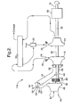
- FIG 2 is similar to figure 1 but differs in that there is no second turbine.
- the first radial flow turbine 24 is arranged to drive an output shaft 70 via the shaft 30 and a continuously variable transmission 68.
- the first radial flow turbine 24 is arranged to drive the second centrifugal flow compressor 48 via the shaft 30, which is clutched to a coaxial shaft 62.
- the shaft 62 is arranged to drive a gearbox 64 and the gearbox 64 is in turn arranged to drive a shaft 66 to which the second centrifugal flow compressor 48 is secured.
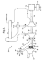
- FIG 3 is similar to figure 1 but differs in that there is no second turbine.
- the first radial flow turbine 24 is arranged to drive an electrical generator 72, for example a high frequency alternator, via the shaft 30.
- the electrical generator 72 supplies electrical power via power electronics 74 to electrical power leads 76.
- the first radial flow turbine 24 is arranged to drive the second centrifugal flow compressor 48 via the shaft 30, which is clutched to a coaxial shaft 62.
- the shaft 62 is arranged to drive a gearbox 64 and the gearbox 64 is in turn arranged to drive a shaft 66 to which the second centrifugal flow compressor 48 is secured.
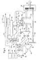
- a further gas turbine engine 310 comprises in flow series an inlet 12, an inlet duct 14, a first centrifugal flow air compressor 16, a diffuser 18, a heat exchanger 20, a combustor 22, a first radial flow turbine 24, a second axial flow turbine 26, the heat exchanger 20 and an exhaust 28.
- the first turbine 24 is arranged to drive the first compressor 16 via a shaft 30.
- the second turbine 26 is arranged to drive an output shaft via a shaft 34 and a first gearbox 36.
- the output shaft 32 is coupled to any suitable load device (not shown), for example, the driving wheels of a motor vehicle or a propeller of a marine vessel or an electric generator.
- the inlet duct 14 includes a stage of variable inlet guide vanes 38 upstream of the first centrifugal flow compressor 16.
- the diffuser includes a stage of variable guide vanes 40.
- the first radial flow turbine 24 includes a stage of variable inlet guide vanes 42 upstream of the first turbine 24 and the second axial flow turbine 26 includes a stage of variable inlet guide vanes 44 upstream of the second turbine 26.
- the combustor 22 is provided with valves (not shown) to vary the flow of air into the combustor 22.
- a second centrifugal flow compressor 48 is arranged upstream of the first centrifugal flow compressor 16.
- the second centrifugal flow compressor 48 has an inlet 46 at its upstream end and an outlet duct 50 at its downstream end.
- the outlet duct 50 is interconnected with the inlet duct 14 of the first radial flow compressor 16 via an aperture 52.
- One or more flap valves 54 are pivotally mounted by pivots 56 on the inlet duct 14 and outlet duct 50 such that in a first position the flap valves 54 are movable between a first position and a second position.
- the second axial flow turbine 26 is arranged to drive the second centrifugal flow compressor 48 via the shaft 34 and the gearbox 36.
- the gearbox 36 also drives a shaft 58, which is clutched to a coaxial shaft 62.
- the shaft 62 is arranged to drive a second gearbox 64 and the second gearbox 64 is in turn arranged to drive a shaft 66 to which the second centrifugal flow compressor 48 is secured.
- a source of water 80 is provided to supply water to the gas turbine engine 10.
- the water is supplied through a treatment plant 82 to produce polished water, which is stored in a polished water tank 84.
- the treatment plant 82 is highly purified to avoid damage to the gas turbine engine from erosion, corrosion or deposition.
- the treatment plant 82 removes dissolved solids, organic material and ions.
- the polished water 84 is supplied to the gas turbine engine 10 by a pump 86.
- the pump 86 is connected, via a pipe 88 and a valve 90, to the outlet duct 50 downstream of the second centrifugal flow compressor 48, upstream of the first centrifugal flow compressor 16.
- the pump 86 is connected via pipes 92 and 94 and valve 96 to a position between the first centrifugal flow compressor 16 and the heat exchanger 20.
- the pump 86 is connected via pipes 92 and 98 and valve 100 to a position between the heat exchanger 20 and the combustor 22.
- the pump 86 is connected via pipes 106 and 108 and valve 110 to a position between the combustor 22 and the first radial flow turbine 24.
- the pump 86 is connected via pipes 106 and 112 and valve 114 to a position between the first radial flow turbine 24 and the second axial flow turbine 26.
- the pump 86 is connected via pipes 106 and 116 and valve 118 to a position between the second axial flow turbine 26 and the heat exchanger 20.
- a condenser 120 is provided downstream of the heat exchanger 20 to remove water from the exhaust gases 28 and the condenser 120 is arranged to supply the recovered water to the water tank 80.
- the water is injected into the gas turbine engine 10 at the appropriate position by any suitable water injection apparatus.
- Additives may be provided in the water, for example methanol, to promote atomisation and/or evaporation by lowering surface tension and to prevent freezing of the stored water.
- the water injection apparatus is arranged to produce water droplets as small as possible so as to avoid erosion and to maximise surface area to maximise evaporation of the water.
- the water droplets have a droplet size of less than 20 ⁇ m, preferably less than 10 ⁇ m and more preferably less than 5 ⁇ m.
- the water injection apparatus may be pressurised such that high-pressure water is swirled in a swirl chamber before being discharged.
- the water injection apparatus may be pressurised such that high-pressure water is discharged at high velocity and is atomised by collision on an impaction member.
- the water injection apparatus may be supplied with a stream of gas such that the low-pressure water is atomised before being discharged.
- the water injection apparatus may be supplied with a gas, which dissolves in the water such that the gas effervesces when the pressure is reduced when the water is discharged to cause the gas containing water droplets to explode into finer water droplets.
- the water injection apparatus may be pressurised, to about 100bar, and heated such that the water droplets are atomised by boiling or flash atomisation.
- valves 90, 96 and 104 In operation of the gas turbine engine 10 at high power levels water is injected into the gas turbine engine 10 to boost the power obtained from a given size of engine 10.
- one or more of the valves 90, 96 and 104 is opened to allow water to be injected into the gas turbine engine 10 upstream of the first centrifugal flow compressor 16, within the first centrifugal flow compressor 16, between the first centrifugal flow compressor 16 and the heat exchanger 20 and within the heat exchanger 20 respectively.
- the valves 90, 96 and 104 are controlled such that the water injection rate at the respective positions is controlled to maximise power boost, for example some of the valves 90, 96 and 104 may be closed.
- the injection of water at any of the points mentioned above boosts the power of the gas turbine engine 10 due to the water mass flow.
- the injection of water at any of the points mentioned increases the efficiency due to a lower temperature of the air at entry to the heat exchanger 20, which increases the heat recovery from the exhaust gases 28.
- the injection of water upstream of the first centrifugal flow compressor 16 produces an inlet cooling effect, which reduces the compressor work and increases the flow through the first centrifugal flow compressor 16, providing a further boost in power.
- the injection of water into the first centrifugal flow compressor 16 produces an inter cooling effect, which reduces the compressor work and increases the flow through the first centrifugal flow compressor 16, providing a further boost in power.
- water may not be injected into the gas turbine engine 10. However, it is preferred that at low power levels water is injected into the gas turbine engine 10 to reduce fuel consumption.
- one or more of the valves 90, 96 and 104 is opened to allow water to be injected into the gas turbine engine 10 upstream of the first centrifugal flow compressor 16, within the first centrifugal flow compressor 16, between the first centrifugal flow compressor 16 and the heat exchanger 20 and within the heat exchanger 20 respectively.
- the valves 90, 96 and 104 are controlled such that the water injection rate at the respective positions is controlled to minimise fuel consumption, for example some of the valves 90, 96 and 104 may be closed.
- variable inlet guide vanes 42 for the first radial flow turbine 24 allows the injection of high flow rates of water without a reduction in the compressor surge margin that would occur with fixed inlet guide vanes.
- variable diffuser vanes 40 for the first centrifugal flow compressor 16 allows the injection of high flow rates of water without a reduction in the compressor surge margin that would occur with fixed inlet guide vanes.
- variable inlet guide vanes 38, the variable diffuser vanes 40, the variable inlet guide vanes 42 and the variable inlet guide vanes 44 allows the flow into the first centrifugal flow compressor 16, the first radial flow turbine 24 and the second axial flow turbine 26 to be controlled to reduce, preferably minimise, erosion of the rotor components by the impacting water droplets.
- valves 90, 96 and 104 are opened to allow water to be injected into the gas turbine engine 10 upstream of the first centrifugal flow compressor 16, within the first centrifugal flow compressor 16, between the first centrifugal flow compressor 16 and the heat exchanger 20 and within the heat exchanger 20 respectively.
- the valves 90, 96 and 104 are controlled such that the water injection rate at the respective positions is controlled to maximise power boost, for example some of the valves 90, 96 and 104 may be closed.
- the valves 90, 96 and 104 and the variable inlet guide vanes 38, the variable diffuser vanes 40, the variable inlet guide vanes 42 and the variable inlet guide vanes 44 are controlled to ensure an adequate surge margin for the first centrifugal flow compressor 16.
- valves 110, 114 and 118 are opened to allow water to be injected into the gas turbine engine 10 upstream of the first radial flow turbine 24, between the first radial flow turbine 24 and the second axial flow turbine 26 or between the second axial flow turbine 26 and the heat exchanger 20.
- the valves 110, 114 and 108 are controlled such that the water injection rate at the respective positions is controlled to maximise power reduction, for example some of the valves 110, 114 and 118 may be closed.
- the power reduction is achieved by reducing temperature levels in the turbines 24 and 26 and counteracts the large heat transfer from the exhaust gases 28 to the air flowing to the combustor 22 by the heat exchanger 20. This also reduces the risk of extinction of combustion in the combustor 22 from the conventional rapid reduction of fuel supply. This may also be used in the event of a shaft breakage, loss of load or emergency shut down conditions.
- the amount of water injected upstream of the heat exchanger 20 air side and/or exhaust gas side may be varied transiently to minimise the thermal cycles experienced by the heat exchanger 20.
- water may be sprayed onto, or flowed within, the compressor and/or turbine casings to control the clearance between the tips of the rotor blades and the casings.
- the water supplied to the gas turbine engine 10 may be heated prior to injection using a heater 122.
- the exhaust gases 28 flow through the heater 122 positioned downstream of the heat exchanger 20. It is preferred that the water supplied from the pipes 94, 98 and 102 is heated by the heater 122 to improve the fuel consumption. It is preferred that the water supplied from the pipe 88 is unheated because heated water will offset the cooling benefit of the injected water.
- the humid air supplied to the combustor 22 reduces the emissions of NOx without the requirement for an exhaust catalyst or a premixed lean burn staged combustion chamber.
- the clutch 60 transmits drive from the shaft 58 to the shaft 62 such that the second centrifugal flow compressor 48 is driven by the second axial flow turbine 26.
- the flap valves 54 are moved to the first position such that air is supplied from the second centrifugal flow compressor 48 to the first centrifugal flow compressor 16.
- the clutch 60 does not transmit drive from the shaft 58 to the shaft 62 such that the second centrifugal flow compressor 48 is not driven by the second axial flow turbine 26.
- the flap valves 54 are moved to the second position such that air is supplied from the inlet 12 to the first centrifugal flow compressor 16.
- the levels of pressure ratio about 4.5:1, is chosen such that increasing pressure ratio increases specific power.
- the power increase is due to the increase in both flow and pressure ratio.
- the use of the second centrifugal flow compressor 48 in the high power level mode of operation requires a relatively long flow path, which increases the residence time for evaporation of the water for the water intercooling.
- variable guide vanes 38, 40, 42, 44 and valves 54 avoids the operational limitations inherent with a conventional fixed geometry engine.
- the pressure ratio and hence the power of the core engine, the first compressor 16, combustor 22 and first turbine 24, may be achieved with a smaller increase in combustor 22 temperature if the second axial flow turbine 26 capacity is increased in relation to that of the first radial flow turbine 24.
- the power may be increased by significantly increasing the pressure ratio as well as the combustor 22 temperature in order to avoid increasing the inlet temperature of the heat exchanger 20 such that the heat exchanger 20 is not damaged.
- the flap valves 54 may be low cost non actuated flap valves 54 such that at low power levels, when the second centrifugal flow compressor 48 inactive, the first centrifugal flow compressor 16 effectively sucks air through the inlet 12 to reduce the pressure loss of sucking through the second centrifugal flow compressor 48 alone. When the second centrifugal flow compressor 48 is active the delivery pressure forces the flap valves 54 to the first position to prevent leakage of air through the inlet 12.
- the flap valves 54 may be moved by powered actuators (not shown), for example hydraulic, pneumatic, electric or mechanical rams.
- the arrangement also enables bleed air to be bled from the duct 14 between the second radial flow compressor 48 and the first radial flow compressor 16 or from the downstream end of the first radial flow compressor 16 of the gas turbine engine 10 at a variety of pressures and power output levels. This is particularly suitable for an aircraft auxiliary power unit gas turbine engine.
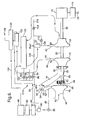
- FIG. 5 A further gas turbine engine 410 according to the present invention is shown in figure 5, and like parts are denoted by like numerals.
- Figure 5 is similar to figure 4 but differs in that there is no second turbine.
- the first radial flow turbine 24 is arranged to drive an output shaft 70 via the shaft 30 and a continuously variable transmission 68.
- the first radial flow turbine 24 is arranged to drive the second centrifugal flow compressor 48 via the shaft 30, which is clutched to a coaxial shaft 62.
- the shaft 62 is arranged to drive a gearbox 64 and the gearbox 64 is in turn arranged to drive a shaft 66 to which the second centrifugal flow compressor 48 is secured. Additionally there is no pipe 112 and valve 114.
- FIG. 6 Another gas turbine engine 510 according to the present invention is shown in figure 6, and like parts are denoted by like numerals.
- Figure 3 is similar to figure 1 but differs in that there is no second turbine.
- the first radial flow turbine 24 is arranged to drive an electrical generator 72, for example a high frequency alternator, via the shaft 30.
- the electrical generator 72 supplies electrical power via power electronics 74 to electrical power leads 76.
- the first radial flow turbine 24 is arranged to drive the second centrifugal flow compressor 48 via the shaft 30, which is clutched to a coaxial shaft 62.
- the shaft 62 is arranged to drive a gearbox 64 and the gearbox 64 is in turn arranged to drive a shaft 66 to which the second centrifugal flow compressor 48 is secured. Additionally there is no pipe 112 and valve 114.
- first centrifugal flow compressor it may be equally possible to use a first axial flow compressor.
- second centrifugal flow compressor it may be equally possible to use a second axial flow compressor.
- first radial flow turbine it may be equally possible to use a first radial flow turbine.
- second axial flow turbine it may be equally possible to use a second radial flow turbine.
Abstract
Description
- The present invention relates to a gas turbine engine and in particular to gas turbine engines for non-aero applications, although it may be applicable to gas turbine engine for aero applications.
- One main consideration for the operation of gas turbine engines is the specific fuel consumption value (SFC), measured in kg/kWhrs. In general for certain gas turbine engine applications especially marine, automotive, aero and even industrial, a significant proportion of operation is at low power. A gas turbine engine utilises hot working fluid expanding through a given expansion ratio in the turbines which produces a power in excess of that required for the compressor to produce the corresponding pressure ratio. This is due to pressure and temperature ratios being proportional to one another during compression or expansion in the simple gas turbine engine cycle, which means that temperature change and hence work, is proportional to the initial temperature level. Therefore reducing the amount of fuel available at part power results in reduced temperature levels and hence a reduced speed and pressure ratio thus resulting in a significant increase in specific fuel consumption (SFC.
- Recuperated gas turbine engines use heat exchangers to return heat from the final turbine exhaust to pre-heat compressed air entering the combustor. This helps to conserve fuel by raising the combustor air temperature and therefore limiting the amount of fuel needed to achieve the turbine inlet temperature.
- Our published International patent application WO9936688A discloses a small gas turbine engine comprising a centrifugal compressor, a diffuser, a heat exchanger, a combustor and at least one turbine. The compressor has variable inlet guide vanes, the diffuser has variable outlet guide vanes and the at least one turbine has variable inlet guide vanes so that the flow capacity of each component is independently variable while maintaining the temperature, pressure ratio and speed of rotation of the gas turbine engine substantially constant.
- Our published European patent application EP1055809A2 discloses a small gas turbine engine comprising a centrifugal compressor, a diffuser, a heat exchanger, a combustor and at least one turbine. The compressor has variable inlet guide vanes, the diffuser has variable outlet guide vanes, the combustor has a variable area inlet and the at least one turbine has variable inlet guide vanes so that the flow capacity of each component is independently variable while maintaining the temperature, pressure ratio and speed of rotation of the gas turbine engine substantially constant.
- An effective way of ensuring low fuel consumption at any specified part power level is to use a smaller gas turbine engine in terms of airflow and power. However, the maximum power required from the gas turbine engine is fixed and hence the gas turbine engine cannot be made smaller in terms of air flow and power.
- Accordingly the present invention seeks to provide a novel gas turbine engine which reduces, preferably overcomes, the above mentioned problems.
- Accordingly the present invention provides a gas turbine engine comprising a first compressor, a combustor and a first turbine arranged in flow series, the first turbine being arranged to drive the first compressor, the first compressor having variable inlet guide vanes, the first turbine having variable inlet guide vanes, a second compressor being arranged upstream of the first compressor, an auxiliary intake being arranged upstream of the first compressor and downstream of the second compressor, valve means being arranged upstream of the first compressor and downstream of the second compressor, the valve means being movable between a first position in which the second compressor supplies fluid to the first compressor and a second position in which the second compressor does not supply fluid to the second compressor and the auxiliary intake supplies fluid to the first compressor and selective drive means being arranged to selectively drive the second compressor.
- Preferably a second turbine is arranged downstream of the first turbine, the second turbine having variable inlet guide vanes.
- Preferably the second turbine is arranged to drive an output shaft. Preferably the second turbine is arranged to drive the output shaft via a gearbox. Preferably the second turbine is arranged to drive the second compressor via the gearbox. Preferably the second turbine is arranged to drive the second compressor via a second gearbox.
- Alternatively the first turbine is arranged to drive an output shaft. The first turbine may be arranged to drive the output shaft via a gearbox. The first turbine may be arranged to drive the second compressor via a second gearbox.
- Preferably the selective drive means comprises a clutch.
- Alternatively the output shaft may be arranged to drive an electrical generator.
- Alternatively the selective drive means comprises the electrical generator driven by the second turbine and an electrical motor arranged to drive the second compressor.
- Preferably the valve means comprises at least one pivotally mounted flap valve. Preferably the valve means comprises a plurality of flap valves.
- Preferably there are means to selectively move the valve means between the first and second positions.
- Preferably a recuperator is arranged between the first compressor and the combustor.
- Preferably the first compressor is a centrifugal flow compressor. Preferably the second compressor is a centrifugal flow compressor.
- Preferably the first turbine is a radial flow turbine. Preferably the second turbine is an axial flow turbine.
- Preferably a diffuser is arranged between the first compressor and the combustor, the diffuser having variable area guide vanes.
- Preferably there are means to inject cooling liquid into the gas turbine engine, the means to inject cooling liquid being arranged to inject cooling liquid upstream of the first compressor, within the first compressor, between the first compressor and the heat exchanger, within the heat exchanger, between the combustor and the first turbine, within the first turbine or between the first turbine and the heat exchanger.
- The means to inject cooling liquid may be arranged to inject cooling liquid between the combustor and the first turbine, within the first turbine or between the first turbine and the heat exchanger.
- The means to inject cooling liquid may be arranged to inject cooling liquid between the first turbine and the second turbine. The means to inject cooling liquid may be arranged to inject cooling liquid between the combustor and the first turbine, within the first turbine, between the first turbine and the second turbine, within the second turbine or between the second turbine and the heat exchanger.
- The present invention will be more fully described by way of example with reference to the accompanying drawings in which:-
- Figure 1 is a schematic diagram of a gas turbine engine according to the present invention.
- Figure 2 is a schematic diagram of a gas turbine engine according to the present invention.
- Figure 3 is a schematic diagram of a gas turbine engine according to the present invention.
- Figure 4 is a schematic diagram of a gas turbine engine according to the present invention.
- Figure 5 is a schematic diagram of a gas turbine engine according to the present invention.
- Figure 6 is a schematic diagram of a gas turbine engine according to the present invention.
-
- A gas turbine engine according to the present invention is particularly suitable for marine and automotive applications, which operate largely at low power. For example an automotive gas turbine engine may utilise 6% of the available power at speeds of approximately 30mph (48km/h), 18% of the available power at speeds of approximately 56mph (90km/h), 35% of the available power at speeds of approximately 75mph (120km/h) for a vehicle with a maximum speed of 115mph (185km/h).
- The
gas turbine engine 10 according to the present invention, as shown in figure 1, comprises in flow series aninlet 12, aninlet duct 14, a first centrifugalflow air compressor 16, adiffuser 18, aheat exchanger 20, acombustor 22, a firstradial flow turbine 24, a secondaxial flow turbine 26, theheat exchanger 20 and anexhaust 28. Thefirst turbine 24 is arranged to drive thefirst compressor 16 via ashaft 30. Thesecond turbine 26 is arranged to drive an output shaft via ashaft 34 and afirst gearbox 36. Theoutput shaft 32 is coupled to any suitable load device (not shown), for example, the driving wheels of a motor vehicle or a propeller of a marine vessel or an electric generator. - The
inlet duct 14 includes a stage of variable inlet guide vanes 38 upstream of the firstcentrifugal flow compressor 16. The diffuser includes a stage of variable guide vanes 40. The firstradial flow turbine 24 includes a stage of variable inlet guide vanes 42 upstream of thefirst turbine 24 and the secondaxial flow turbine 26 includes a stage of variable inlet guide vanes 44 upstream of thesecond turbine 26. Thecombustor 22 is provided with valves (not shown) to vary the flow of air into thecombustor 22. - A second
centrifugal flow compressor 48 is arranged upstream of the firstcentrifugal flow compressor 16. The secondcentrifugal flow compressor 48 has aninlet 46 at its upstream end and anoutlet duct 50 at its downstream end. Theoutlet duct 50 is interconnected with theinlet duct 14 of the firstradial flow compressor 16 via anaperture 52. One ormore flap valves 54 are pivotally mounted bypivots 56 on theinlet duct 14 andoutlet duct 50 such that in a first position theflap valves 54 are movable between a first position and a second position. - In the first position the
flap valves 54 open theaperture 52 such that the secondcentrifugal flow compressor 48 supplies air to the firstcentrifugal flow compressor 16 and theflap valves 54 close theinlet 12 such that air is not supplied from theinlet 12 to the firstcentrifugal flow compressor 16. - In the second position the
flap valves 54 open theinlet 12 such that theinlet 12 supplies air to the firstcentrifugal flow compressor 16 and theflap valves 54 close theaperture 52 such that air is not supplied from the secondcentrifugal flow compressor 48 to the firstcentrifugal flow compressor 16. - The second
axial flow turbine 26 is arranged to drive the secondcentrifugal flow compressor 48 via theshaft 34 and thegearbox 36. Thegearbox 36 also drives ashaft 58, which is clutched to acoaxial shaft 62. Theshaft 62 is arranged to drive asecond gearbox 64 and thesecond gearbox 64 is in turn arranged to drive ashaft 66 to which the secondcentrifugal flow compressor 48 is secured. - In operation of the
gas turbine engine 10 at high power levels the clutch 60 transmits drive from theshaft 58 to theshaft 62 such that the secondcentrifugal flow compressor 48 is driven by the secondaxial flow turbine 26. Theflap valves 54 are moved to the first position such that air is supplied from the secondcentrifugal flow compressor 48 to the firstcentrifugal flow compressor 16. - In operation of the
gas turbine engine 10 at low power levels the clutch 60 does not transmit drive from theshaft 58 to theshaft 62 such that the secondcentrifugal flow compressor 48 is not driven by the secondaxial flow turbine 26. Theflap valves 54 are moved to the second position such that air is supplied from theinlet 12 to the firstcentrifugal flow compressor 16. - The levels of pressure ratio, about 4.5:1, is chosen such that increasing pressure ratio increases specific power. The power increase is due to the increase in both flow and pressure ratio.
- The
variable guide vanes valves 54 avoids the operational limitations inherent with a conventional fixed geometry engine. For example, the pressure ratio and hence the power of the core engine, thefirst compressor 16,combustor 22 andfirst turbine 24, may be achieved with a smaller increase incombustor 22 temperature if the secondaxial flow turbine 26 capacity is increased in relation to that of the firstradial flow turbine 24. - The power may be increased by significantly increasing the pressure ratio as well as the
combustor 22 temperature in order to avoid increasing the inlet temperature of theheat exchanger 20 such that theheat exchanger 20 is not damaged. - The
flap valves 54 may be low cost non actuatedflap valves 54 such that at low power levels, when the secondcentrifugal flow compressor 48 inactive, the firstcentrifugal flow compressor 16 effectively sucks air through theinlet 12 to reduce the pressure loss of sucking through the secondcentrifugal flow compressor 48 alone. When the secondcentrifugal flow compressor 48 is active the delivery pressure forces theflap valves 54 to the first position to prevent leakage of air through theinlet 12. - The
flap valves 54 may be moved by powered actuators (not shown), for example hydraulic, pneumatic, electric or mechanical rams. - It may be possible to use the air drawn into the
inlet 46 to drive the secondcentrifugal flow compressor 48, when the secondaxial flow turbine 26 is not driving the secondcentrifugal flow compressor 48, to maintain the secondcentrifugal flow compressor 48 at a significant rotational speed. This reduces the time lag in engine response that may occur when accelerating the secondcentrifugal flow compressor 48 from rest and also reduce the wear on the clutch 60 andgearboxes - The arrangement also enables bleed air to be bled from the
duct 14 between the secondradial flow compressor 48 and the firstradial flow compressor 16 or from the downstream end of the firstradial flow compressor 16 of thegas turbine engine 10 at a variety of pressures and power output levels. This is particularly suitable for an aircraft auxiliary power unit gas turbine engine. - A further
gas turbine engine 110 according to the present invention is shown in figure 2, and like parts are denoted by like numerals. Figure 2 is similar to figure 1 but differs in that there is no second turbine. In this embodiment the firstradial flow turbine 24 is arranged to drive anoutput shaft 70 via theshaft 30 and a continuouslyvariable transmission 68. The firstradial flow turbine 24 is arranged to drive the secondcentrifugal flow compressor 48 via theshaft 30, which is clutched to acoaxial shaft 62. Theshaft 62 is arranged to drive agearbox 64 and thegearbox 64 is in turn arranged to drive ashaft 66 to which the secondcentrifugal flow compressor 48 is secured. - Another
gas turbine engine 210 according to the present invention is shown in figure 3, and like parts are denoted by like numerals. Figure 3 is similar to figure 1 but differs in that there is no second turbine. In this embodiment the firstradial flow turbine 24 is arranged to drive anelectrical generator 72, for example a high frequency alternator, via theshaft 30. Theelectrical generator 72 supplies electrical power viapower electronics 74 to electrical power leads 76. The firstradial flow turbine 24 is arranged to drive the secondcentrifugal flow compressor 48 via theshaft 30, which is clutched to acoaxial shaft 62. Theshaft 62 is arranged to drive agearbox 64 and thegearbox 64 is in turn arranged to drive ashaft 66 to which the secondcentrifugal flow compressor 48 is secured. - A further
gas turbine engine 310 according to the present invention, as shown in figure 4, comprises in flow series aninlet 12, aninlet duct 14, a first centrifugalflow air compressor 16, adiffuser 18, aheat exchanger 20, acombustor 22, a firstradial flow turbine 24, a secondaxial flow turbine 26, theheat exchanger 20 and anexhaust 28. Thefirst turbine 24 is arranged to drive thefirst compressor 16 via ashaft 30. Thesecond turbine 26 is arranged to drive an output shaft via ashaft 34 and afirst gearbox 36. Theoutput shaft 32 is coupled to any suitable load device (not shown), for example, the driving wheels of a motor vehicle or a propeller of a marine vessel or an electric generator. - The
inlet duct 14 includes a stage of variableinlet guide vanes 38 upstream of the firstcentrifugal flow compressor 16. The diffuser includes a stage of variable guide vanes 40. The firstradial flow turbine 24 includes a stage of variableinlet guide vanes 42 upstream of thefirst turbine 24 and the secondaxial flow turbine 26 includes a stage of variableinlet guide vanes 44 upstream of thesecond turbine 26. Thecombustor 22 is provided with valves (not shown) to vary the flow of air into thecombustor 22. - A second
centrifugal flow compressor 48 is arranged upstream of the firstcentrifugal flow compressor 16. The secondcentrifugal flow compressor 48 has aninlet 46 at its upstream end and anoutlet duct 50 at its downstream end. Theoutlet duct 50 is interconnected with theinlet duct 14 of the firstradial flow compressor 16 via anaperture 52. One ormore flap valves 54 are pivotally mounted bypivots 56 on theinlet duct 14 andoutlet duct 50 such that in a first position theflap valves 54 are movable between a first position and a second position. - In the first position the
flap valves 54 open theaperture 52 such that the secondcentrifugal flow compressor 48 supplies air to the firstcentrifugal flow compressor 16 and theflap valves 54 close theinlet 12 such that air is not supplied from theinlet 12 to the firstcentrifugal flow compressor 16. - In the second position the
flap valves 54 open theinlet 12 such that theinlet 12 supplies air to the firstcentrifugal flow compressor 16 and theflap valves 54 close theaperture 52 such that air is not supplied from the secondcentrifugal flow compressor 48 to the firstcentrifugal flow compressor 16. - The second
axial flow turbine 26 is arranged to drive the secondcentrifugal flow compressor 48 via theshaft 34 and thegearbox 36. Thegearbox 36 also drives ashaft 58, which is clutched to acoaxial shaft 62. Theshaft 62 is arranged to drive asecond gearbox 64 and thesecond gearbox 64 is in turn arranged to drive ashaft 66 to which the secondcentrifugal flow compressor 48 is secured. - A source of
water 80 is provided to supply water to thegas turbine engine 10. The water is supplied through atreatment plant 82 to produce polished water, which is stored in apolished water tank 84. Thetreatment plant 82 is highly purified to avoid damage to the gas turbine engine from erosion, corrosion or deposition. Thetreatment plant 82 removes dissolved solids, organic material and ions. Thepolished water 84 is supplied to thegas turbine engine 10 by apump 86. - The
pump 86 is connected, via apipe 88 and avalve 90, to theoutlet duct 50 downstream of the secondcentrifugal flow compressor 48, upstream of the firstcentrifugal flow compressor 16. Thepump 86 is connected viapipes valve 96 to a position between the firstcentrifugal flow compressor 16 and theheat exchanger 20. Thepump 86 is connected viapipes valve 100 to a position between theheat exchanger 20 and thecombustor 22. Thepump 86 is connected viapipes valve 110 to a position between the combustor 22 and the firstradial flow turbine 24. Thepump 86 is connected viapipes 106 and 112 andvalve 114 to a position between the firstradial flow turbine 24 and the secondaxial flow turbine 26. Thepump 86 is connected viapipes valve 118 to a position between the secondaxial flow turbine 26 and theheat exchanger 20. - A
condenser 120 is provided downstream of theheat exchanger 20 to remove water from theexhaust gases 28 and thecondenser 120 is arranged to supply the recovered water to thewater tank 80. - The water is injected into the
gas turbine engine 10 at the appropriate position by any suitable water injection apparatus. Additives may be provided in the water, for example methanol, to promote atomisation and/or evaporation by lowering surface tension and to prevent freezing of the stored water. The water injection apparatus is arranged to produce water droplets as small as possible so as to avoid erosion and to maximise surface area to maximise evaporation of the water. The water droplets have a droplet size of less than 20µm, preferably less than 10µm and more preferably less than 5µm. - The water injection apparatus may be pressurised such that high-pressure water is swirled in a swirl chamber before being discharged. The water injection apparatus may be pressurised such that high-pressure water is discharged at high velocity and is atomised by collision on an impaction member. The water injection apparatus may be supplied with a stream of gas such that the low-pressure water is atomised before being discharged. The water injection apparatus may be supplied with a gas, which dissolves in the water such that the gas effervesces when the pressure is reduced when the water is discharged to cause the gas containing water droplets to explode into finer water droplets. The water injection apparatus may be pressurised, to about 100bar, and heated such that the water droplets are atomised by boiling or flash atomisation.
- In operation of the
gas turbine engine 10 at high power levels water is injected into thegas turbine engine 10 to boost the power obtained from a given size ofengine 10. At high power levels one or more of thevalves gas turbine engine 10 upstream of the firstcentrifugal flow compressor 16, within the firstcentrifugal flow compressor 16, between the firstcentrifugal flow compressor 16 and theheat exchanger 20 and within theheat exchanger 20 respectively. Thevalves valves - At any given temperature of combustion in the
combustor 22, the injection of water at any of the points mentioned above boosts the power of thegas turbine engine 10 due to the water mass flow. The injection of water at any of the points mentioned increases the efficiency due to a lower temperature of the air at entry to theheat exchanger 20, which increases the heat recovery from theexhaust gases 28. The injection of water upstream of the firstcentrifugal flow compressor 16 produces an inlet cooling effect, which reduces the compressor work and increases the flow through the firstcentrifugal flow compressor 16, providing a further boost in power. The injection of water into the firstcentrifugal flow compressor 16 produces an inter cooling effect, which reduces the compressor work and increases the flow through the firstcentrifugal flow compressor 16, providing a further boost in power. - The fact that the high power levels only occur intermittently means that the size and weight of the
tanks tanks gas turbine engine 10 by impacts from the water droplets. - This enables the
gas turbine engine 10 to be sized smaller and still be able to meet the given duty and this provides a substantial fuel saving at low power levels and at high power levels. - In operation of the
gas turbine engine 10 at low power levels water may not be injected into thegas turbine engine 10. However, it is preferred that at low power levels water is injected into thegas turbine engine 10 to reduce fuel consumption. At low power levels one or more of thevalves gas turbine engine 10 upstream of the firstcentrifugal flow compressor 16, within the firstcentrifugal flow compressor 16, between the firstcentrifugal flow compressor 16 and theheat exchanger 20 and within theheat exchanger 20 respectively. Thevalves valves - The provision of the variable
inlet guide vanes 42 for the firstradial flow turbine 24 allows the injection of high flow rates of water without a reduction in the compressor surge margin that would occur with fixed inlet guide vanes. The provision ofvariable diffuser vanes 40 for the firstcentrifugal flow compressor 16 allows the injection of high flow rates of water without a reduction in the compressor surge margin that would occur with fixed inlet guide vanes. - The provision of variable
inlet guide vanes 38, thevariable diffuser vanes 40, the variableinlet guide vanes 42 and the variableinlet guide vanes 44 allows the flow into the firstcentrifugal flow compressor 16, the firstradial flow turbine 24 and the secondaxial flow turbine 26 to be controlled to reduce, preferably minimise, erosion of the rotor components by the impacting water droplets. - During an acceleration of the
gas turbine engine 10 water is injected into thegas turbine engine 10 to quickly boost the power from thegas turbine engine 10. During acceleration one or more of thevalves gas turbine engine 10 upstream of the firstcentrifugal flow compressor 16, within the firstcentrifugal flow compressor 16, between the firstcentrifugal flow compressor 16 and theheat exchanger 20 and within theheat exchanger 20 respectively. Thevalves valves valves inlet guide vanes 38, thevariable diffuser vanes 40, the variableinlet guide vanes 42 and the variableinlet guide vanes 44 are controlled to ensure an adequate surge margin for the firstcentrifugal flow compressor 16. - During a deceleration of the
gas turbine engine 10 water is injected into thegas turbine engine 10 to quickly reduce the power from thegas turbine engine 10. During deceleration one or more of thevalves gas turbine engine 10 upstream of the firstradial flow turbine 24, between the firstradial flow turbine 24 and the secondaxial flow turbine 26 or between the secondaxial flow turbine 26 and theheat exchanger 20. Thevalves valves turbines exhaust gases 28 to the air flowing to thecombustor 22 by theheat exchanger 20. This also reduces the risk of extinction of combustion in the combustor 22 from the conventional rapid reduction of fuel supply. This may also be used in the event of a shaft breakage, loss of load or emergency shut down conditions. - The amount of water injected upstream of the
heat exchanger 20 air side and/or exhaust gas side may be varied transiently to minimise the thermal cycles experienced by theheat exchanger 20. - Additionally water may be sprayed onto, or flowed within, the compressor and/or turbine casings to control the clearance between the tips of the rotor blades and the casings.
- The water supplied to the
gas turbine engine 10 may be heated prior to injection using aheater 122. Theexhaust gases 28 flow through theheater 122 positioned downstream of theheat exchanger 20. It is preferred that the water supplied from thepipes heater 122 to improve the fuel consumption. It is preferred that the water supplied from thepipe 88 is unheated because heated water will offset the cooling benefit of the injected water. - The humid air supplied to the
combustor 22 reduces the emissions of NOx without the requirement for an exhaust catalyst or a premixed lean burn staged combustion chamber. - In operation of the
gas turbine engine 10 at high power levels the clutch 60 transmits drive from theshaft 58 to theshaft 62 such that the secondcentrifugal flow compressor 48 is driven by the secondaxial flow turbine 26. Theflap valves 54 are moved to the first position such that air is supplied from the secondcentrifugal flow compressor 48 to the firstcentrifugal flow compressor 16. - In operation of the
gas turbine engine 10 at low power levels the clutch 60 does not transmit drive from theshaft 58 to theshaft 62 such that the secondcentrifugal flow compressor 48 is not driven by the secondaxial flow turbine 26. Theflap valves 54 are moved to the second position such that air is supplied from theinlet 12 to the firstcentrifugal flow compressor 16. - The levels of pressure ratio, about 4.5:1, is chosen such that increasing pressure ratio increases specific power. The power increase is due to the increase in both flow and pressure ratio.
- The use of the second
centrifugal flow compressor 48 in the high power level mode of operation requires a relatively long flow path, which increases the residence time for evaporation of the water for the water intercooling. - The
variable guide vanes valves 54 avoids the operational limitations inherent with a conventional fixed geometry engine. For example, the pressure ratio and hence the power of the core engine, thefirst compressor 16,combustor 22 andfirst turbine 24, may be achieved with a smaller increase incombustor 22 temperature if the secondaxial flow turbine 26 capacity is increased in relation to that of the firstradial flow turbine 24. - The power may be increased by significantly increasing the pressure ratio as well as the
combustor 22 temperature in order to avoid increasing the inlet temperature of theheat exchanger 20 such that theheat exchanger 20 is not damaged. - The
flap valves 54 may be low cost non actuatedflap valves 54 such that at low power levels, when the secondcentrifugal flow compressor 48 inactive, the firstcentrifugal flow compressor 16 effectively sucks air through theinlet 12 to reduce the pressure loss of sucking through the secondcentrifugal flow compressor 48 alone. When the secondcentrifugal flow compressor 48 is active the delivery pressure forces theflap valves 54 to the first position to prevent leakage of air through theinlet 12. - The
flap valves 54 may be moved by powered actuators (not shown), for example hydraulic, pneumatic, electric or mechanical rams. - It may be possible to use the air drawn into the
inlet 46 to drive the secondcentrifugal flow compressor 48, when the secondaxial flow turbine 26 is not driving the secondcentrifugal flow compressor 48, to maintain the secondcentrifugal flow compressor 48 at a significant rotational speed. This reduces the time lag in engine response that may occur when accelerating the secondcentrifugal flow compressor 48 from rest and also reduce the wear on the clutch 60 andgearboxes - The arrangement also enables bleed air to be bled from the
duct 14 between the secondradial flow compressor 48 and the firstradial flow compressor 16 or from the downstream end of the firstradial flow compressor 16 of thegas turbine engine 10 at a variety of pressures and power output levels. This is particularly suitable for an aircraft auxiliary power unit gas turbine engine. - A further
gas turbine engine 410 according to the present invention is shown in figure 5, and like parts are denoted by like numerals. Figure 5 is similar to figure 4 but differs in that there is no second turbine. In this embodiment the firstradial flow turbine 24 is arranged to drive anoutput shaft 70 via theshaft 30 and a continuouslyvariable transmission 68. The firstradial flow turbine 24 is arranged to drive the secondcentrifugal flow compressor 48 via theshaft 30, which is clutched to acoaxial shaft 62. Theshaft 62 is arranged to drive agearbox 64 and thegearbox 64 is in turn arranged to drive ashaft 66 to which the secondcentrifugal flow compressor 48 is secured. Additionally there is no pipe 112 andvalve 114. - Another
gas turbine engine 510 according to the present invention is shown in figure 6, and like parts are denoted by like numerals. Figure 3 is similar to figure 1 but differs in that there is no second turbine. In this embodiment the firstradial flow turbine 24 is arranged to drive anelectrical generator 72, for example a high frequency alternator, via theshaft 30. Theelectrical generator 72 supplies electrical power viapower electronics 74 to electrical power leads 76. The firstradial flow turbine 24 is arranged to drive the secondcentrifugal flow compressor 48 via theshaft 30, which is clutched to acoaxial shaft 62. Theshaft 62 is arranged to drive agearbox 64 and thegearbox 64 is in turn arranged to drive ashaft 66 to which the secondcentrifugal flow compressor 48 is secured. Additionally there is no pipe 112 andvalve 114. - Although the present invention has been described with reference to the injection of water into the gas turbine engine it may be possible to use other suitable liquids, which evaporate to cool the air or working fluid supplied to the combustor.
- Although the invention has been described with reference to a first centrifugal flow compressor it may be equally possible to use a first axial flow compressor. Similarly although the invention has been described with reference to a second centrifugal flow compressor it may be equally possible to use a second axial flow compressor. Although the invention has been described with reference to a first radial flow turbine it may be equally possible to use a second axial flow turbine. Although the invention has been described with reference to a second axial flow turbine it may be equally possible to use a second radial flow turbine.
Claims (21)
- A gas turbine engine (10) comprising a first compressor (16), a combustor (22) and a first turbine (24) arranged in flow series, the first turbine (24) being arranged to drive the first compressor (16), the first compressor (16) having variable inlet guide vanes (38), the first turbine (24) having variable inlet guide vanes (42), characterised in that a second compressor (48) being arranged upstream of the first compressor (16), an auxiliary intake (12) being arranged upstream of the first compressor (16) and downstream of the second compressor (48), valve means (54) being arranged upstream of the first compressor (16) and downstream of the second compressor (48), the valve means (54) being movable between a first position in which the second compressor (48) supplies fluid to the first compressor (16) and a second position in which the second compressor (48) does not supply fluid to the first compressor (16) and the auxiliary intake (12) supplies fluid to the first compressor (16) and selective drive means (60) being arranged to selectively drive the second compressor (48).
- A gas turbine engine as claimed in claim 1 wherein a second turbine (26) is arranged downstream of the first turbine (24), the second turbine (26) having variable inlet guide vanes (44).
- A gas turbine engine as claimed in claim 2 wherein the second turbine (26) is arranged to drive an output shaft (30).
- A gas turbine engine as claimed in claim 3 wherein the second turbine (26) is arranged to drive the output shaft (32) via a gearbox (36).
- A gas turbine engine as claimed in claim 4 wherein the second turbine (26) is arranged to drive the second compressor (48) via the gearbox (36).
- A gas turbine engine as claimed in claim 1 wherein the first turbine (24) is arranged to drive an output shaft (30).
- A gas turbine engine as claimed in claim 6 wherein the first turbine (24) is arranged to drive the output shaft (70) via a gearbox (68).
- A gas turbine engine as claimed in claim 6 or claim 7 wherein the first turbine (24) is arranged to drive the second compressor (48) via a second gearbox (64).
- A gas turbine engine as claimed in claim 5 wherein a second turbine (26) is arranged to drive the second compressor (48) via a second gearbox (64).
- A gas turbine engine as claimed in any of claims 1 to 9 wherein the selective drive means (60) comprises a clutch.
- A gas turbine engine as claimed in claim 3, claim 4 or claim 6 wherein the output shaft (30) is arranged to drive an electrical generator (72).
- A gas turbine engine as claimed in claim 11 wherein the selective drive means comprises an electrical generator (72) arranged to be driven by the output shaft (30) and an electrical motor arranged to drive the second compressor (48).
- A gas turbine engine as claimed in any of claims 1 to 12 wherein the valve means (54) comprises at least one pivotally mounted flap valve.
- A gas turbine engine as claimed in claim 13 wherein the valve means (54) comprises a plurality of flap valves.
- A gas turbine engine as claimed in claim 13 or claim 14 wherein there are means to selectively move the valve means (54) between the first and second positions.
- A gas turbine engine as claimed in any of claims 1 to 15 wherein a heat exchanger (20) is arranged between the first compressor (16) and the combustor (22).
- A gas turbine engine as claimed in claim 16 comprising means to inject a cooling liquid into the gas turbine engine (10), the means to inject cooling liquid (84,86,88,94,102) arranged to inject cooling liquid upstream of the first compressor (16), within the first compressor (16) between the first compressor (16) and the heat exchanger (20), within the heat exchanger (20)
- A gas turbine engine as claimed in any of claims 1 to 15 comprising means to inject a cooling liquid into the gas turbine engine (10), the means to inject cooling liquid (84,86,108,116) being arranged to inject cooling liquid between the combustor (22) and the first turbine (24), within the first turbine (24) or between the first turbine (24) and the heat exchanger (20).
- A gas turbine engine as claimed in any of claims 2 to 5 comprising means to inject a cooling liquid into the gas turbine engine (10), the means to inject cooling liquid (84,86,112) being arranged to inject cooling liquid between the first turbine (24) and the second turbine (26).
- A gas turbine engine as claimed in claim 16 when dependent upon any of claims 2 to 5 comprising means to inject a cooling liquid into the gas turbine engine (10), the means to inject cooling liquid (84,86,108,112,116) being arranged to inject cooling liquid between the combustor (22) and the first turbine (24), within the first turbine (24), between the first turbine (24) and the second turbine (26), within the second turbine (26) or between the second turbine (26) and the heat exchanger (20).
- A gas turbine engine as claimed in any of claims 1 to 20 wherein a diffuser is arranged between the first compressor (16) and the combustor (22), the diffuser having variable area guide vanes (40).
Applications Claiming Priority (4)
| Application Number | Priority Date | Filing Date | Title |
|---|---|---|---|
| GB0211349 | 2002-05-16 | ||
| GB0211348 | 2002-05-16 | ||
| GB0211348A GB0211348D0 (en) | 2002-05-16 | 2002-05-16 | A gas turbine engine |
| GB0211349A GB0211349D0 (en) | 2002-05-16 | 2002-05-16 | A gas turbine engine |
Publications (3)
| Publication Number | Publication Date |
|---|---|
| EP1362984A2 true EP1362984A2 (en) | 2003-11-19 |
| EP1362984A3 EP1362984A3 (en) | 2006-09-06 |
| EP1362984B1 EP1362984B1 (en) | 2007-04-25 |
Family
ID=29272007
Family Applications (1)
| Application Number | Title | Priority Date | Filing Date |
|---|---|---|---|
| EP03252779A Expired - Fee Related EP1362984B1 (en) | 2002-05-16 | 2003-05-02 | Gas turbine engine |
Country Status (3)
| Country | Link |
|---|---|
| US (1) | US6865891B2 (en) |
| EP (1) | EP1362984B1 (en) |
| DE (1) | DE60313392T2 (en) |
Cited By (12)
| Publication number | Priority date | Publication date | Assignee | Title |
|---|---|---|---|---|
| EP1365127A2 (en) * | 2002-05-16 | 2003-11-26 | ROLLS-ROYCE plc | Gas turbine engine and method of operating such a gas turbine engine |
| WO2007024674A2 (en) * | 2005-08-22 | 2007-03-01 | Teledyne Technologies Incorporated | Turbine engine having two off-axis spools with valving-enabled modulation between high and low power modes |
| EP2052967A1 (en) | 2007-10-26 | 2009-04-29 | Eurocopter | Improvement for rotorcraft equipped with turboshaft engines |
| LU91310B1 (en) * | 2007-01-30 | 2009-11-09 | Philippe Camus | Electro-hydraulic decoupling with pneumatic over-compression of low-pressure compressors or turbo-rotating propellers |
| WO2010009708A1 (en) * | 2008-07-19 | 2010-01-28 | Mtu Aero Engines Gmbh | Engine comprising a core engine and thruster connected downstream |
| EP2325456A1 (en) | 2009-11-19 | 2011-05-25 | Douglas Wilbert Paul Smith | Gas turbine cycle with water injection for generating electricity |
| EP2366874A1 (en) * | 2010-03-16 | 2011-09-21 | Samsung Techwin Co., Ltd | Turbine system with several independent compressors and turbines |
| ITCO20100029A1 (en) * | 2010-05-24 | 2011-11-25 | Nuovo Pignone Spa | METHODS AND SYSTEMS FOR INPUT NOZZLES WITH VARIABLE GEOMETRY FOR USE IN TURBOESPANSORI |
| WO2014016498A1 (en) * | 2012-07-24 | 2014-01-30 | Vianney Rabhi | Internal and/or external combustion turbine engine |
| WO2014071037A3 (en) * | 2012-11-02 | 2014-07-17 | General Electric Company | System and method for oxidant compression in a stoichiometric exhaust gas recirculation gas turbine system |
| EP2834500B1 (en) * | 2012-04-02 | 2019-06-19 | United Technologies Corporation | Turbomachine thermal management system and method |
| CN111794864A (en) * | 2019-04-05 | 2020-10-20 | 通用电气公司 | Pump mixer separator unit |
Families Citing this family (117)
| Publication number | Priority date | Publication date | Assignee | Title |
|---|---|---|---|---|
| US6968701B2 (en) * | 2002-01-16 | 2005-11-29 | United Technologies Corporation | Engine integrated auxiliary power unit |
| AU2003243627A1 (en) * | 2002-06-18 | 2003-12-31 | Ingersoll-Rand Energy Systems Corporation | Microturbine engine system |
| US7089744B2 (en) * | 2004-07-21 | 2006-08-15 | Steward Davis International, Inc. | Onboard supplemental power system at varying high altitudes |
| US7111462B2 (en) * | 2004-07-21 | 2006-09-26 | Steward-Davis International, Inc. | Onboard supplemental power system at varying high altitudes |
| US7291934B2 (en) * | 2005-08-30 | 2007-11-06 | Caterpillar Inc. | Machine with an electrical system |
| US20070265761A1 (en) * | 2006-05-11 | 2007-11-15 | Dooley Kevin A | Electric power generation system and method |
| US7752835B2 (en) * | 2006-06-01 | 2010-07-13 | United Technologies Corporation | Pulsed combustion engine |
| WO2008105815A2 (en) * | 2006-08-22 | 2008-09-04 | Rolls-Royce North American Technologies, Inc. | Gas turbine engine with intermediate speed booster |
| CN1959120A (en) * | 2006-11-07 | 2007-05-09 | 杨学实 | Electric aviation compressor |
| US9719428B2 (en) * | 2007-11-30 | 2017-08-01 | United Technologies Corporation | Gas turbine engine with pylon mounted accessory drive |
| US8169100B2 (en) * | 2008-01-30 | 2012-05-01 | Pratt & Whitney Canada Corp. | Torque transmission for an aircraft engine |
| US20090205341A1 (en) * | 2008-02-20 | 2009-08-20 | Muldoon Marc J | Gas turbine engine with twin towershaft accessory gearbox |
| CA2934541C (en) | 2008-03-28 | 2018-11-06 | Exxonmobil Upstream Research Company | Low emission power generation and hydrocarbon recovery systems and methods |
| WO2009121008A2 (en) | 2008-03-28 | 2009-10-01 | Exxonmobil Upstream Research Company | Low emission power generation and hydrocarbon recovery systems and methods |
| US8181442B2 (en) * | 2008-05-05 | 2012-05-22 | Pratt & Whitney Canada Corp. | Gas turbine aircraft engine with power variability |
| US8061973B2 (en) * | 2008-07-14 | 2011-11-22 | General Electric Company | Turbomachine including an adaptable intake system and method of controlling airflow to a turbomachine |
| US9080578B2 (en) * | 2008-09-02 | 2015-07-14 | Hamilton Sundstrand Corporation | Compact drive for compressor variable diffuser |
| EP2344738B1 (en) | 2008-10-14 | 2019-04-03 | Exxonmobil Upstream Research Company | Method and system for controlling the products of combustion |
| US8256202B1 (en) | 2008-11-25 | 2012-09-04 | Florida Turbine Technologies, Inc. | High bypass turbofan |
| US8468835B2 (en) * | 2009-03-27 | 2013-06-25 | Solar Turbines Inc. | Hybrid gas turbine engine—electric motor/generator drive system |
| US9816441B2 (en) * | 2009-03-30 | 2017-11-14 | United Technologies Corporation | Gas turbine engine with stacked accessory components |
| US8356486B2 (en) * | 2009-06-12 | 2013-01-22 | Hamilton Sundstrand Corporation | APU bleed valve with integral anti-surge port |
| US20110167784A1 (en) * | 2009-09-25 | 2011-07-14 | James Edward Johnson | Method of operating a convertible fan engine |
| US20110167831A1 (en) * | 2009-09-25 | 2011-07-14 | James Edward Johnson | Adaptive core engine |
| US20110167792A1 (en) * | 2009-09-25 | 2011-07-14 | James Edward Johnson | Adaptive engine |
| DE102009046076A1 (en) * | 2009-10-28 | 2011-05-12 | Robert Bosch Gmbh | Generator unit, in particular for motor vehicles |
| EA023673B1 (en) | 2009-11-12 | 2016-06-30 | Эксонмобил Апстрим Рисерч Компани | Low emission power generation and hydrocarbon recovery system and method |
| WO2011142787A2 (en) * | 2009-12-30 | 2011-11-17 | Rolls-Royce North American Technologies, Inc. | Gas turbine engine system with bleed air powered auxiliary engine |
| EP2553251B1 (en) | 2010-03-26 | 2018-11-07 | Rolls-Royce North American Technologies, Inc. | Adaptive fan system for a variable cycle turbofan engine |
| JP5906555B2 (en) | 2010-07-02 | 2016-04-20 | エクソンモービル アップストリーム リサーチ カンパニー | Stoichiometric combustion of rich air by exhaust gas recirculation system |
| MX341981B (en) | 2010-07-02 | 2016-09-08 | Exxonmobil Upstream Res Company * | Stoichiometric combustion with exhaust gas recirculation and direct contact cooler. |
| CA2801488C (en) | 2010-07-02 | 2018-11-06 | Exxonmobil Upstream Research Company | Low emission triple-cycle power generation systems and methods |
| JP5913305B2 (en) | 2010-07-02 | 2016-04-27 | エクソンモービル アップストリーム リサーチ カンパニー | Low emission power generation system and method |
| US8519555B2 (en) | 2010-11-29 | 2013-08-27 | Pratt & Whitney Canada Corp. | Combination low spool generator and ram air turbine generator |
| TWI564474B (en) | 2011-03-22 | 2017-01-01 | 艾克頌美孚上游研究公司 | Integrated systems for controlling stoichiometric combustion in turbine systems and methods of generating power using the same |
| TWI563166B (en) | 2011-03-22 | 2016-12-21 | Exxonmobil Upstream Res Co | Integrated generation systems and methods for generating power |
| TWI593872B (en) | 2011-03-22 | 2017-08-01 | 艾克頌美孚上游研究公司 | Integrated system and methods of generating power |
| TWI563165B (en) | 2011-03-22 | 2016-12-21 | Exxonmobil Upstream Res Co | Power generation system and method for generating power |
| US8844266B1 (en) * | 2011-10-03 | 2014-09-30 | Florida Turbine Technologies, Inc. | Variable bypass ratio augmented gas turbine engine |
| CN104428490B (en) | 2011-12-20 | 2018-06-05 | 埃克森美孚上游研究公司 | The coal bed methane production of raising |
| US8459038B1 (en) | 2012-02-09 | 2013-06-11 | Williams International Co., L.L.C. | Two-spool turboshaft engine control system and method |
| US9115593B2 (en) * | 2012-04-02 | 2015-08-25 | United Technologies Corporation | Turbomachine thermal management |
| US9353682B2 (en) | 2012-04-12 | 2016-05-31 | General Electric Company | Methods, systems and apparatus relating to combustion turbine power plants with exhaust gas recirculation |
| EP2841740B1 (en) * | 2012-04-26 | 2020-04-01 | General Electric Company | System and method of recirculating exhaust gas for use in a plurality of flow paths in a gas turbine engine |
| US10273880B2 (en) | 2012-04-26 | 2019-04-30 | General Electric Company | System and method of recirculating exhaust gas for use in a plurality of flow paths in a gas turbine engine |
| US9784185B2 (en) | 2012-04-26 | 2017-10-10 | General Electric Company | System and method for cooling a gas turbine with an exhaust gas provided by the gas turbine |
| US8607576B1 (en) * | 2012-06-07 | 2013-12-17 | United Technologies Corporation | Single turbine driving dual compressors |
| US9708977B2 (en) | 2012-12-28 | 2017-07-18 | General Electric Company | System and method for reheat in gas turbine with exhaust gas recirculation |
| US9631815B2 (en) | 2012-12-28 | 2017-04-25 | General Electric Company | System and method for a turbine combustor |
| US10107495B2 (en) | 2012-11-02 | 2018-10-23 | General Electric Company | Gas turbine combustor control system for stoichiometric combustion in the presence of a diluent |
| US9869279B2 (en) | 2012-11-02 | 2018-01-16 | General Electric Company | System and method for a multi-wall turbine combustor |
| US10215412B2 (en) | 2012-11-02 | 2019-02-26 | General Electric Company | System and method for load control with diffusion combustion in a stoichiometric exhaust gas recirculation gas turbine system |
| US9611756B2 (en) | 2012-11-02 | 2017-04-04 | General Electric Company | System and method for protecting components in a gas turbine engine with exhaust gas recirculation |
| US9574496B2 (en) | 2012-12-28 | 2017-02-21 | General Electric Company | System and method for a turbine combustor |
| US10100741B2 (en) | 2012-11-02 | 2018-10-16 | General Electric Company | System and method for diffusion combustion with oxidant-diluent mixing in a stoichiometric exhaust gas recirculation gas turbine system |
| US9803865B2 (en) | 2012-12-28 | 2017-10-31 | General Electric Company | System and method for a turbine combustor |
| US10208677B2 (en) | 2012-12-31 | 2019-02-19 | General Electric Company | Gas turbine load control system |
| US9581081B2 (en) | 2013-01-13 | 2017-02-28 | General Electric Company | System and method for protecting components in a gas turbine engine with exhaust gas recirculation |
| US9512759B2 (en) | 2013-02-06 | 2016-12-06 | General Electric Company | System and method for catalyst heat utilization for gas turbine with exhaust gas recirculation |
| TW201502356A (en) | 2013-02-21 | 2015-01-16 | Exxonmobil Upstream Res Co | Reducing oxygen in a gas turbine exhaust |
| US9938861B2 (en) | 2013-02-21 | 2018-04-10 | Exxonmobil Upstream Research Company | Fuel combusting method |
| US10221762B2 (en) | 2013-02-28 | 2019-03-05 | General Electric Company | System and method for a turbine combustor |
| TW201500635A (en) | 2013-03-08 | 2015-01-01 | Exxonmobil Upstream Res Co | Processing exhaust for use in enhanced oil recovery |
| US9618261B2 (en) | 2013-03-08 | 2017-04-11 | Exxonmobil Upstream Research Company | Power generation and LNG production |
| US20140250945A1 (en) | 2013-03-08 | 2014-09-11 | Richard A. Huntington | Carbon Dioxide Recovery |
| CN105008499A (en) | 2013-03-08 | 2015-10-28 | 埃克森美孚上游研究公司 | Power generation and methane recovery from methane hydrates |
| US9605557B1 (en) | 2013-04-30 | 2017-03-28 | United States Of America As Represented By The Secretary Of The Air Force | Variable bypass turbofan engine |
| TWI654368B (en) | 2013-06-28 | 2019-03-21 | 美商艾克頌美孚上游研究公司 | System, method and media for controlling exhaust gas flow in an exhaust gas recirculation gas turbine system |
| US9835089B2 (en) | 2013-06-28 | 2017-12-05 | General Electric Company | System and method for a fuel nozzle |
| US9631542B2 (en) | 2013-06-28 | 2017-04-25 | General Electric Company | System and method for exhausting combustion gases from gas turbine engines |
| US9617914B2 (en) | 2013-06-28 | 2017-04-11 | General Electric Company | Systems and methods for monitoring gas turbine systems having exhaust gas recirculation |
| US20160069264A1 (en) * | 2013-07-22 | 2016-03-10 | Joseph D. Brostmeyer | Gas turbine engine with turbine cooling and combustor air preheating |
| US9903588B2 (en) | 2013-07-30 | 2018-02-27 | General Electric Company | System and method for barrier in passage of combustor of gas turbine engine with exhaust gas recirculation |
| US9587510B2 (en) | 2013-07-30 | 2017-03-07 | General Electric Company | System and method for a gas turbine engine sensor |
| US9617917B2 (en) | 2013-07-31 | 2017-04-11 | General Electric Company | Flow control assembly and methods of assembling the same |
| US9951658B2 (en) | 2013-07-31 | 2018-04-24 | General Electric Company | System and method for an oxidant heating system |
| DE102013112892A1 (en) * | 2013-11-21 | 2015-05-21 | Deutsches Zentrum für Luft- und Raumfahrt e.V. | Micro gas turbine arrangement |
| JP6248124B2 (en) * | 2013-11-27 | 2017-12-13 | 株式会社日立製作所 | Renewable energy compatible gas turbine and control method thereof |
| US9752458B2 (en) | 2013-12-04 | 2017-09-05 | General Electric Company | System and method for a gas turbine engine |
| US10030588B2 (en) | 2013-12-04 | 2018-07-24 | General Electric Company | Gas turbine combustor diagnostic system and method |
| US10227920B2 (en) | 2014-01-15 | 2019-03-12 | General Electric Company | Gas turbine oxidant separation system |
| US9915200B2 (en) | 2014-01-21 | 2018-03-13 | General Electric Company | System and method for controlling the combustion process in a gas turbine operating with exhaust gas recirculation |
| US9863267B2 (en) | 2014-01-21 | 2018-01-09 | General Electric Company | System and method of control for a gas turbine engine |
| US10079564B2 (en) | 2014-01-27 | 2018-09-18 | General Electric Company | System and method for a stoichiometric exhaust gas recirculation gas turbine system |
| US9567871B2 (en) * | 2014-04-23 | 2017-02-14 | Sikorsky Aircraft Corporation | Impeller retention apparatus |
| US10047633B2 (en) | 2014-05-16 | 2018-08-14 | General Electric Company | Bearing housing |
| US9885290B2 (en) | 2014-06-30 | 2018-02-06 | General Electric Company | Erosion suppression system and method in an exhaust gas recirculation gas turbine system |
| US10655542B2 (en) | 2014-06-30 | 2020-05-19 | General Electric Company | Method and system for startup of gas turbine system drive trains with exhaust gas recirculation |
| US10060359B2 (en) | 2014-06-30 | 2018-08-28 | General Electric Company | Method and system for combustion control for gas turbine system with exhaust gas recirculation |
| GB201414661D0 (en) * | 2014-08-19 | 2014-10-01 | Rolls Royce Plc | Gas turbine engine and method of operation |
| US20160160761A1 (en) * | 2014-12-09 | 2016-06-09 | United Technologies Corporation | Gas Turbine Engine With Single Turbine Driving Two Compressors |
| US9869247B2 (en) | 2014-12-31 | 2018-01-16 | General Electric Company | Systems and methods of estimating a combustion equivalence ratio in a gas turbine with exhaust gas recirculation |
| US9819292B2 (en) | 2014-12-31 | 2017-11-14 | General Electric Company | Systems and methods to respond to grid overfrequency events for a stoichiometric exhaust recirculation gas turbine |
| US10788212B2 (en) | 2015-01-12 | 2020-09-29 | General Electric Company | System and method for an oxidant passageway in a gas turbine system with exhaust gas recirculation |
| US10316746B2 (en) | 2015-02-04 | 2019-06-11 | General Electric Company | Turbine system with exhaust gas recirculation, separation and extraction |
| US10094566B2 (en) | 2015-02-04 | 2018-10-09 | General Electric Company | Systems and methods for high volumetric oxidant flow in gas turbine engine with exhaust gas recirculation |
| US10253690B2 (en) | 2015-02-04 | 2019-04-09 | General Electric Company | Turbine system with exhaust gas recirculation, separation and extraction |
| US10267270B2 (en) | 2015-02-06 | 2019-04-23 | General Electric Company | Systems and methods for carbon black production with a gas turbine engine having exhaust gas recirculation |
| US20160237904A1 (en) * | 2015-02-13 | 2016-08-18 | General Electric Company | Systems and methods for controlling an inlet air temperature of an intercooled gas turbine engine |
| US10145269B2 (en) | 2015-03-04 | 2018-12-04 | General Electric Company | System and method for cooling discharge flow |
| US10480792B2 (en) | 2015-03-06 | 2019-11-19 | General Electric Company | Fuel staging in a gas turbine engine |
| US11415063B2 (en) | 2016-09-15 | 2022-08-16 | Pratt & Whitney Canada Corp. | Reverse-flow gas turbine engine |
| US10883424B2 (en) | 2016-07-19 | 2021-01-05 | Pratt & Whitney Canada Corp. | Multi-spool gas turbine engine architecture |
| US10465611B2 (en) | 2016-09-15 | 2019-11-05 | Pratt & Whitney Canada Corp. | Reverse flow multi-spool gas turbine engine with aft-end accessory gearbox drivingly connected to both high pressure spool and low pressure spool |
| US11035293B2 (en) | 2016-09-15 | 2021-06-15 | Pratt & Whitney Canada Corp. | Reverse flow gas turbine engine with offset RGB |
| US10815899B2 (en) | 2016-11-15 | 2020-10-27 | Pratt & Whitney Canada Corp. | Gas turbine engine accessories arrangement |
| US10533559B2 (en) | 2016-12-20 | 2020-01-14 | Pratt & Whitney Canada Corp. | Reverse flow engine architecture |
| US10808624B2 (en) | 2017-02-09 | 2020-10-20 | Pratt & Whitney Canada Corp. | Turbine rotor with low over-speed requirements |
| US10738709B2 (en) | 2017-02-09 | 2020-08-11 | Pratt & Whitney Canada Corp. | Multi-spool gas turbine engine |
| US10215052B2 (en) | 2017-03-14 | 2019-02-26 | Pratt & Whitney Canada Corp. | Inter-shaft bearing arrangement |
| US10746188B2 (en) * | 2017-03-14 | 2020-08-18 | Pratt & Whitney Canada Corp. | Inter-shaft bearing connected to a compressor boost system |
| CN110821677A (en) | 2018-08-08 | 2020-02-21 | 普拉特 - 惠特尼加拿大公司 | Multi-engine system and method |
| US11339721B2 (en) | 2018-11-14 | 2022-05-24 | Honeywell International Inc. | System and method for supplying compressed air to a main engine starter motor |
| US11668245B2 (en) * | 2020-01-28 | 2023-06-06 | Pratt & Whitney Canada Corp. | Gas turbine engine with clutch system between low-pressure compressor and low-pressure turbine |
| US11473442B1 (en) * | 2020-09-22 | 2022-10-18 | Aetherdynamic Power Systems Llc | Re-circulating heat pump turbine |
| WO2023014635A1 (en) * | 2021-08-03 | 2023-02-09 | Gts Research & Engineering, Llc | Injection techniques for gas turbine systems |
| FR3128492A1 (en) * | 2021-10-27 | 2023-04-28 | Safran Power Units | AUXILIARY POWER UNIT WITH INTEGRATED CHARGE COMPRESSOR |
Citations (4)
| Publication number | Priority date | Publication date | Assignee | Title |
|---|---|---|---|---|
| US3585795A (en) * | 1967-12-30 | 1971-06-22 | Daimler Benz Ag | Gas turbine assembly having low-pressure groups and high-pressure groups adapted to be selectively connected either in series or in parallel |
| GB2280223A (en) * | 1988-06-28 | 1995-01-25 | Rolls Royce Plc | Valve for diverting fluid flows in turbomachines |
| WO1999036688A1 (en) * | 1998-01-15 | 1999-07-22 | Rolls-Royce Plc | Gas turbine engine |
| EP1055809A2 (en) * | 1999-05-22 | 2000-11-29 | Rolls-Royce Plc | A gas turbine engine and a method of controlling a gas turbine engine |
Family Cites Families (11)
| Publication number | Priority date | Publication date | Assignee | Title |
|---|---|---|---|---|
| US3548597A (en) * | 1968-09-16 | 1970-12-22 | Alexander Hossen Etessam | Turbine engine for aircraft having a supplementary compressor driven by a supplementary turbine |
| US3899886A (en) * | 1973-11-19 | 1975-08-19 | Gen Motors Corp | Gas turbine engine control |
| GB1605303A (en) * | 1976-03-09 | 1988-10-05 | Rolls Royce | Dual cycle gas turbine engine |
| US4160362A (en) * | 1977-03-31 | 1979-07-10 | Westinghouse Electric Corp. | Gas turbine and combined cycle power plant having reduced emission of nitrogen oxide and improved coolant injection flow control system therefor |
| GB2301402B (en) | 1988-12-02 | 1997-09-03 | Rolls Royce Plc | Valve for diverting fluid flows in gas turbine engines |
| DE19539774A1 (en) | 1995-10-26 | 1997-04-30 | Asea Brown Boveri | Intercooled compressor |
| JPH10103080A (en) | 1996-09-30 | 1998-04-21 | Ishikawajima Harima Heavy Ind Co Ltd | Gas turbine cycle |
| JPH11324710A (en) * | 1998-05-20 | 1999-11-26 | Hitachi Ltd | Gas turbine power plant |
| US6484508B2 (en) * | 1998-07-24 | 2002-11-26 | General Electric Company | Methods for operating gas turbine engines |
| GB9911867D0 (en) * | 1999-05-22 | 1999-07-21 | Rolls Royce Plc | A combustion chamber assembly and a method of operating a combustion chamber assembly |
| EP1491557A1 (en) | 2003-06-27 | 2004-12-29 | Cerestar Holding B.V. | Resistant starch compositions |
-
2003
- 2003-05-02 EP EP03252779A patent/EP1362984B1/en not_active Expired - Fee Related
- 2003-05-02 DE DE60313392T patent/DE60313392T2/en not_active Expired - Lifetime
- 2003-05-08 US US10/431,400 patent/US6865891B2/en not_active Expired - Fee Related
Patent Citations (4)
| Publication number | Priority date | Publication date | Assignee | Title |
|---|---|---|---|---|
| US3585795A (en) * | 1967-12-30 | 1971-06-22 | Daimler Benz Ag | Gas turbine assembly having low-pressure groups and high-pressure groups adapted to be selectively connected either in series or in parallel |
| GB2280223A (en) * | 1988-06-28 | 1995-01-25 | Rolls Royce Plc | Valve for diverting fluid flows in turbomachines |
| WO1999036688A1 (en) * | 1998-01-15 | 1999-07-22 | Rolls-Royce Plc | Gas turbine engine |
| EP1055809A2 (en) * | 1999-05-22 | 2000-11-29 | Rolls-Royce Plc | A gas turbine engine and a method of controlling a gas turbine engine |
Cited By (27)
| Publication number | Priority date | Publication date | Assignee | Title |
|---|---|---|---|---|
| EP1365127A2 (en) * | 2002-05-16 | 2003-11-26 | ROLLS-ROYCE plc | Gas turbine engine and method of operating such a gas turbine engine |
| EP1365127A3 (en) * | 2002-05-16 | 2004-11-17 | ROLLS-ROYCE plc | Gas turbine engine and method of operating such a gas turbine engine |
| US6968698B2 (en) | 2002-05-16 | 2005-11-29 | Rolls-Royce Plc | Gas turbine engine |
| WO2007024674A2 (en) * | 2005-08-22 | 2007-03-01 | Teledyne Technologies Incorporated | Turbine engine having two off-axis spools with valving-enabled modulation between high and low power modes |
| WO2007024674A3 (en) * | 2005-08-22 | 2007-06-14 | Teledyne Tech Inc | Turbine engine having two off-axis spools with valving-enabled modulation between high and low power modes |
| US7762085B2 (en) | 2005-08-22 | 2010-07-27 | Teledyne Technologies Incorporated | Turbine engine having two off-axis spools with valving-enabled modulation between high and low power modes |
| LU91310B1 (en) * | 2007-01-30 | 2009-11-09 | Philippe Camus | Electro-hydraulic decoupling with pneumatic over-compression of low-pressure compressors or turbo-rotating propellers |
| EP2052967A1 (en) | 2007-10-26 | 2009-04-29 | Eurocopter | Improvement for rotorcraft equipped with turboshaft engines |
| FR2922860A1 (en) * | 2007-10-26 | 2009-05-01 | Eurocopter France | IMPROVEMENT TO GIRAVIONS EQUIPPED WITH TURBOMOTORS |
| WO2010009708A1 (en) * | 2008-07-19 | 2010-01-28 | Mtu Aero Engines Gmbh | Engine comprising a core engine and thruster connected downstream |
| EP2325456A1 (en) | 2009-11-19 | 2011-05-25 | Douglas Wilbert Paul Smith | Gas turbine cycle with water injection for generating electricity |
| WO2011061079A1 (en) | 2009-11-19 | 2011-05-26 | Boyce, Conor | Gas turbine cycle with water injection for generating electricity |
| EP2366874A1 (en) * | 2010-03-16 | 2011-09-21 | Samsung Techwin Co., Ltd | Turbine system with several independent compressors and turbines |
| US8745991B2 (en) | 2010-03-16 | 2014-06-10 | Samsung Techwin Co., Ltd. | Turbine system |
| RU2565679C2 (en) * | 2010-05-24 | 2015-10-20 | Нуово Пиньоне С.п.А. | Electric power generator and power generation process |
| EP2390470A1 (en) * | 2010-05-24 | 2011-11-30 | Nuovo Pignone S.p.A. | Methods and systems for variable geometry inlets nozzles for use in turboexpanders |
| US8882438B2 (en) | 2010-05-24 | 2014-11-11 | Nuovo Pignone S.P.A. | Methods and systems for variable geometry inlets nozzles for use in turboexpanders |
| ITCO20100029A1 (en) * | 2010-05-24 | 2011-11-25 | Nuovo Pignone Spa | METHODS AND SYSTEMS FOR INPUT NOZZLES WITH VARIABLE GEOMETRY FOR USE IN TURBOESPANSORI |
| EP2834500B1 (en) * | 2012-04-02 | 2019-06-19 | United Technologies Corporation | Turbomachine thermal management system and method |
| WO2014016498A1 (en) * | 2012-07-24 | 2014-01-30 | Vianney Rabhi | Internal and/or external combustion turbine engine |
| FR2993928A1 (en) * | 2012-07-24 | 2014-01-31 | Vianney Rabhi | INTERNAL AND / OR EXTERNAL COMBUSTION LOW PRESSURE TURBOMOTOR |
| FR2993929A1 (en) * | 2012-07-24 | 2014-01-31 | Vianney Rabhi | INTERNAL AND / OR EXTERNAL COMBUSTION LOW PRESSURE TURBOMOTOR |
| FR2993926A1 (en) * | 2012-07-24 | 2014-01-31 | Vianney Rabhi | INTERNAL AND / OR EXTERNAL COMBUSTION LOW PRESSURE TURBOMOTOR |
| WO2014071037A3 (en) * | 2012-11-02 | 2014-07-17 | General Electric Company | System and method for oxidant compression in a stoichiometric exhaust gas recirculation gas turbine system |
| US10683801B2 (en) | 2012-11-02 | 2020-06-16 | General Electric Company | System and method for oxidant compression in a stoichiometric exhaust gas recirculation gas turbine system |
| CN111794864A (en) * | 2019-04-05 | 2020-10-20 | 通用电气公司 | Pump mixer separator unit |
| CN111794864B (en) * | 2019-04-05 | 2023-08-04 | 通用电气公司 | Pump mixer separator unit |
Also Published As
| Publication number | Publication date |
|---|---|
| US20040006994A1 (en) | 2004-01-15 |
| EP1362984B1 (en) | 2007-04-25 |
| DE60313392D1 (en) | 2007-06-06 |
| US6865891B2 (en) | 2005-03-15 |
| EP1362984A3 (en) | 2006-09-06 |
| DE60313392T2 (en) | 2007-08-09 |
Similar Documents
| Publication | Publication Date | Title |
|---|---|---|
| EP1362984B1 (en) | Gas turbine engine | |
| EP1365127B1 (en) | Gas turbine engine and method of operating such a gas turbine engine | |
| CN110529256B (en) | Air cycle assembly for a gas turbine engine assembly | |
| EP3318743B1 (en) | Intercooled cooled cooling integrated air cycle machine | |
| US5363641A (en) | Integrated auxiliary power system | |
| CN1188588C (en) | Gas turbine | |
| US7246482B2 (en) | Gas turbine engine bleed air power assist system and method | |
| US9797311B2 (en) | Integrated thermal system for a gas turbine engine | |
| US9038397B2 (en) | Gas turbine engine thermal management system | |
| US5136837A (en) | Aircraft engine starter integrated boundary bleed system | |
| CN101092907B (en) | Method and device for controlling cooling air temperature of gas turbine engine | |
| US20130098047A1 (en) | Compartment cooling for a gas turbine engine | |
| US8966876B2 (en) | Controllable speed windmill operation of a gas turbine engine through low spool power extraction | |
| CN101649781A (en) | Jet engine | |
| US20060075754A1 (en) | Aeroengine oil tank fire protection system | |
| US20130284398A1 (en) | Gas turbine engine thermal management system | |
| US11781484B2 (en) | Secondary fuel flow demand fuel pumping system | |
| EP3357631B1 (en) | Heat pipe cooling of geared architecture | |
| CN116163838A (en) | Gas supply system | |
| CN111561396B (en) | Hydraulic drive local pump | |
| EP3287620B1 (en) | Boost compressor for engine cooling circuit driven by low spool | |
| EP1378633A2 (en) | Methods and apparatus for operating gas turbine engines | |
| EP3483418B1 (en) | Intercooled cooled cooling integrated air cycle machine | |
| EP4339433A1 (en) | Bottoming cycle for waste heat recovery and engine cooling | |
| CN117469028A (en) | thermal management system |
Legal Events
| Date | Code | Title | Description |
|---|---|---|---|
| PUAI | Public reference made under article 153(3) epc to a published international application that has entered the european phase |
Free format text: ORIGINAL CODE: 0009012 |
|
| AK | Designated contracting states |
Kind code of ref document: A2 Designated state(s): AT BE BG CH CY CZ DE DK EE ES FI FR GB GR HU IE IT LI LU MC NL PT RO SE SI SK TR |
|
| AX | Request for extension of the european patent |
Extension state: AL LT LV MK |
|
| PUAL | Search report despatched |
Free format text: ORIGINAL CODE: 0009013 |
|
| AK | Designated contracting states |
Kind code of ref document: A3 Designated state(s): AT BE BG CH CY CZ DE DK EE ES FI FR GB GR HU IE IT LI LU MC NL PT RO SE SI SK TR |
|
| AX | Request for extension of the european patent |
Extension state: AL LT LV MK |
|
| RIC1 | Information provided on ipc code assigned before grant |
Ipc: F02C 3/13 20060101AFI20060801BHEP Ipc: F02C 6/18 20060101ALI20060801BHEP Ipc: F02C 3/113 20060101ALI20060801BHEP Ipc: F02C 3/10 20060101ALI20060801BHEP Ipc: F01D 17/16 20060101ALI20060801BHEP Ipc: F02C 3/30 20060101ALI20060801BHEP Ipc: F02C 7/08 20060101ALI20060801BHEP |
|
| 17P | Request for examination filed |
Effective date: 20060817 |
|
| GRAP | Despatch of communication of intention to grant a patent |
Free format text: ORIGINAL CODE: EPIDOSNIGR1 |
|
| GRAS | Grant fee paid |
Free format text: ORIGINAL CODE: EPIDOSNIGR3 |
|
| GRAA | (expected) grant |
Free format text: ORIGINAL CODE: 0009210 |
|
| AK | Designated contracting states |
Kind code of ref document: B1 Designated state(s): DE FR GB |
|
| REG | Reference to a national code |
Ref country code: GB Ref legal event code: FG4D |
|
| AKX | Designation fees paid |
Designated state(s): DE FR GB |
|
| REF | Corresponds to: |
Ref document number: 60313392 Country of ref document: DE Date of ref document: 20070606 Kind code of ref document: P |
|
| ET | Fr: translation filed | ||
| PLBE | No opposition filed within time limit |
Free format text: ORIGINAL CODE: 0009261 |
|
| STAA | Information on the status of an ep patent application or granted ep patent |
Free format text: STATUS: NO OPPOSITION FILED WITHIN TIME LIMIT |
|
| 26N | No opposition filed |
Effective date: 20080128 |
|
| REG | Reference to a national code |
Ref country code: FR Ref legal event code: PLFP Year of fee payment: 13 |
|
| PGFP | Annual fee paid to national office [announced via postgrant information from national office to epo] |
Ref country code: DE Payment date: 20150528 Year of fee payment: 13 Ref country code: GB Payment date: 20150527 Year of fee payment: 13 |
|
| PGFP | Annual fee paid to national office [announced via postgrant information from national office to epo] |
Ref country code: FR Payment date: 20150519 Year of fee payment: 13 |
|
| REG | Reference to a national code |
Ref country code: DE Ref legal event code: R119 Ref document number: 60313392 Country of ref document: DE |
|
| GBPC | Gb: european patent ceased through non-payment of renewal fee |
Effective date: 20160502 |
|
| REG | Reference to a national code |
Ref country code: FR Ref legal event code: ST Effective date: 20170131 |
|
| PG25 | Lapsed in a contracting state [announced via postgrant information from national office to epo] |
Ref country code: FR Free format text: LAPSE BECAUSE OF NON-PAYMENT OF DUE FEES Effective date: 20160531 Ref country code: DE Free format text: LAPSE BECAUSE OF NON-PAYMENT OF DUE FEES Effective date: 20161201 |
|
| PG25 | Lapsed in a contracting state [announced via postgrant information from national office to epo] |
Ref country code: GB Free format text: LAPSE BECAUSE OF NON-PAYMENT OF DUE FEES Effective date: 20160502 |