EP1422775A1 - Pile à combustible ayant des plaques séparatrices à passages du gaz en forme de peigne - Google Patents
Pile à combustible ayant des plaques séparatrices à passages du gaz en forme de peigne Download PDFInfo
- Publication number
- EP1422775A1 EP1422775A1 EP03023110A EP03023110A EP1422775A1 EP 1422775 A1 EP1422775 A1 EP 1422775A1 EP 03023110 A EP03023110 A EP 03023110A EP 03023110 A EP03023110 A EP 03023110A EP 1422775 A1 EP1422775 A1 EP 1422775A1
- Authority
- EP
- European Patent Office
- Prior art keywords
- gas
- gas passage
- upstream side
- passage
- comb tooth
- Prior art date
- Legal status (The legal status is an assumption and is not a legal conclusion. Google has not performed a legal analysis and makes no representation as to the accuracy of the status listed.)
- Granted
Links
Images


Classifications
-
- H—ELECTRICITY
- H01—ELECTRIC ELEMENTS
- H01M—PROCESSES OR MEANS, e.g. BATTERIES, FOR THE DIRECT CONVERSION OF CHEMICAL ENERGY INTO ELECTRICAL ENERGY
- H01M8/00—Fuel cells; Manufacture thereof
- H01M8/02—Details
- H01M8/0202—Collectors; Separators, e.g. bipolar separators; Interconnectors
- H01M8/0258—Collectors; Separators, e.g. bipolar separators; Interconnectors characterised by the configuration of channels, e.g. by the flow field of the reactant or coolant
- H01M8/026—Collectors; Separators, e.g. bipolar separators; Interconnectors characterised by the configuration of channels, e.g. by the flow field of the reactant or coolant characterised by grooves, e.g. their pitch or depth
-
- H—ELECTRICITY
- H01—ELECTRIC ELEMENTS
- H01M—PROCESSES OR MEANS, e.g. BATTERIES, FOR THE DIRECT CONVERSION OF CHEMICAL ENERGY INTO ELECTRICAL ENERGY
- H01M8/00—Fuel cells; Manufacture thereof
- H01M8/02—Details
- H01M8/0202—Collectors; Separators, e.g. bipolar separators; Interconnectors
- H01M8/0258—Collectors; Separators, e.g. bipolar separators; Interconnectors characterised by the configuration of channels, e.g. by the flow field of the reactant or coolant
- H01M8/0263—Collectors; Separators, e.g. bipolar separators; Interconnectors characterised by the configuration of channels, e.g. by the flow field of the reactant or coolant having meandering or serpentine paths
-
- H—ELECTRICITY
- H01—ELECTRIC ELEMENTS
- H01M—PROCESSES OR MEANS, e.g. BATTERIES, FOR THE DIRECT CONVERSION OF CHEMICAL ENERGY INTO ELECTRICAL ENERGY
- H01M8/00—Fuel cells; Manufacture thereof
- H01M8/02—Details
- H01M8/0202—Collectors; Separators, e.g. bipolar separators; Interconnectors
- H01M8/0267—Collectors; Separators, e.g. bipolar separators; Interconnectors having heating or cooling means, e.g. heaters or coolant flow channels
-
- H—ELECTRICITY
- H01—ELECTRIC ELEMENTS
- H01M—PROCESSES OR MEANS, e.g. BATTERIES, FOR THE DIRECT CONVERSION OF CHEMICAL ENERGY INTO ELECTRICAL ENERGY
- H01M8/00—Fuel cells; Manufacture thereof
- H01M8/04—Auxiliary arrangements, e.g. for control of pressure or for circulation of fluids
- H01M8/04082—Arrangements for control of reactant parameters, e.g. pressure or concentration
- H01M8/04089—Arrangements for control of reactant parameters, e.g. pressure or concentration of gaseous reactants
-
- H—ELECTRICITY
- H01—ELECTRIC ELEMENTS
- H01M—PROCESSES OR MEANS, e.g. BATTERIES, FOR THE DIRECT CONVERSION OF CHEMICAL ENERGY INTO ELECTRICAL ENERGY
- H01M8/00—Fuel cells; Manufacture thereof
- H01M8/24—Grouping of fuel cells, e.g. stacking of fuel cells
- H01M8/2465—Details of groupings of fuel cells
- H01M8/2483—Details of groupings of fuel cells characterised by internal manifolds
-
- H—ELECTRICITY
- H01—ELECTRIC ELEMENTS
- H01M—PROCESSES OR MEANS, e.g. BATTERIES, FOR THE DIRECT CONVERSION OF CHEMICAL ENERGY INTO ELECTRICAL ENERGY
- H01M8/00—Fuel cells; Manufacture thereof
- H01M8/04—Auxiliary arrangements, e.g. for control of pressure or for circulation of fluids
- H01M8/04082—Arrangements for control of reactant parameters, e.g. pressure or concentration
- H01M8/04089—Arrangements for control of reactant parameters, e.g. pressure or concentration of gaseous reactants
- H01M8/04119—Arrangements for control of reactant parameters, e.g. pressure or concentration of gaseous reactants with simultaneous supply or evacuation of electrolyte; Humidifying or dehumidifying
-
- Y—GENERAL TAGGING OF NEW TECHNOLOGICAL DEVELOPMENTS; GENERAL TAGGING OF CROSS-SECTIONAL TECHNOLOGIES SPANNING OVER SEVERAL SECTIONS OF THE IPC; TECHNICAL SUBJECTS COVERED BY FORMER USPC CROSS-REFERENCE ART COLLECTIONS [XRACs] AND DIGESTS
- Y02—TECHNOLOGIES OR APPLICATIONS FOR MITIGATION OR ADAPTATION AGAINST CLIMATE CHANGE
- Y02E—REDUCTION OF GREENHOUSE GAS [GHG] EMISSIONS, RELATED TO ENERGY GENERATION, TRANSMISSION OR DISTRIBUTION
- Y02E60/00—Enabling technologies; Technologies with a potential or indirect contribution to GHG emissions mitigation
- Y02E60/30—Hydrogen technology
- Y02E60/50—Fuel cells
Definitions
- This invention relates to a constitution of a gas passage and a cooling water passage in a fuel cell.
- JP11-16591A published by the Japan Patent Office in 1999, employs a constitution in which a gas supply passage that communicates with a gas supply port and a gas discharge passage that communicates with a gas discharge port are separated such that all of the gas in the gas supply passage passes through the electrode layer and catalyst layer to be discharged to the gas discharge passage.
- this constitution water droplets and unwanted gas such as nitrogen in the vicinity of the catalyst layer is forcibly discharged, and hence gas no longer has to be blown at high pressure and high speed.
- the aforementioned constitution may have an excellent drainage property, but when the fuel cell is driven in a state of such low humidity that the dew point of the supplied gas falls far below the temperature of the fuel cell, the gas drains water from the electrolyte membrane such that the electrolyte membrane dries and electrical resistance increases. This problem is particularly striking near the cathode passage inlet.
- a further object of this invention is to prevent flooding caused when water generated in the electrodes accumulates in the electrodes and on the gas diffusion layer.
- this invention provides a fuel cell comprising a membrane electrode assembly having an electrolyte membrane interposed between a catalyst layer and a gas diffusion layer on both sides thereof, and a cathode side bipolar plate and an anode side bipolar plate provided on opposite sides of the membrane electrode assembly, an oxidizer gas passage being formed in the cathode side bipolar plate and a fuel gas passage being formed in the anode side bipolar plate.
- the oxidizer gas passage formed in the cathode side bipolar plate comprises an upstream side gas passage which communicates with an oxidizer gas supply port, a first comb tooth-form gas passage provided downstream of the upstream side gas passage, which communicates with the upstream side gas passage but does not communicate with an oxidizer gas discharge port, and a second comb tooth-form gas passage provided downstream of the upstream side gas passage, which does not communicate with either the upstream side gas passage or the first comb tooth-form gas passage, but communicates with the oxidizer gas discharge port.
- FIG. 1 is a schematic diagram of a fuel cell according to this invention.
- FIG. 2 is a sectional view of a membrane electrode assembly.
- FIG. 3 is a view showing a constitution of a gas passage in a cathode side bipolar plate.
- FIG. 4 is a view showing another example of a constitution of a gas passage in the cathode side bipolar plate.
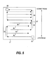
- FIG. 5 is a view showing a constitution of a gas passage in an anode side bipolar plate.
- FIG. 6 is a view showing a constitution of a cooling water passage in a cooling water plate.
- a fuel cell 1 is constituted by laminating together unit cells 10 comprising a cooling water plate 2, a cathode side bipolar plate 4, a membrane electrode assembly 6, and an anode side bipolar plate 8.
- the membrane electrode assembly 6 comprises catalyst layers 5 on both sides of a polymer electrolyte membrane (electrolyte membrane) 3, and gas diffusion layers 7 covering the outer sides of the catalyst layers 5.
- the membrane electrode assembly 6 is interposed between the cathode side bipolar plate 4 and anode side bipolar plate 8.
- a passage for allowing the flow of gas is formed in each of the cathode side bipolar plate 4 and anode side bipolar plate 8, and when oxidizer gas (oxygen, for example) is supplied to the gas passage on the cathode side and fuel gas (hydrogen, for example) is supplied to the gas passage on the anode side, the gas flows into the gas diffusion layer 7, causing an electrochemical reaction in the catalyst layer 5 such that electrical energy can be emitted outside.
- oxidizer gas oxygen, for example
- fuel gas hydrogen, for example
- FIGS. 3 through 6 the constitution of the gas passages formed in the cathode side bipolar plate 4 and anode side bipolar plate 8, and the cooling water passage formed in the cooling water plate 2 will be described.
- FIG. 3 is a view of the cathode side bipolar plate 4 seen from the membrane electrode assembly 6 side.
- a gas supply port 41 and a gas discharge port 45 open in the top left and bottom right of the drawing respectively.
- Oxidizer gas introduced from the gas supply port 41 passes through the gas passage formed in the plate 4 and flows in the downward direction of the drawing to be discharged from the gas discharge port 45.
- the arrows depicted on the plate 4 in the drawing indicate the flow direction of the oxidizer gas.
- the gas passage formed in the plate 4 is constituted by an upstream side gas passage 42 which communicates with the gas supply port 41, a first comb tooth-form gas passage 43 provided downstream of the upstream side gas passage 42, which communicates with the furthest downstream portion of the upstream side gas passage 42 but does not communicate with the gas discharge port 45, and a second comb tooth-form gas passage 44 provided downstream of the upstream side gas passage 42, which communicates with the gas discharge port 45 but does not communicate with either the upstream side gas passage 42 or the first comb tooth-form gas passage 43.
- the connecting position of the upstream side gas passage 42 and first comb tooth-form gas passage 43 will be referred to as an intermediate connection point 47.
- the upstream side gas passage 42 is a series of passages meandering between the gas supply outlet 41 and intermediate connection point 47 so as to connect the gas supply outlet 41 and intermediate connection point 47.
- the upstream side gas passage 42 comprises double-back portions 42r for reversing the flow direction of the gas, and is constructed such that the oxidizer gas supplied from the gas supply port 41 flows downstream in a wide reciprocating motion between the left and right of the plate 4. It should be noted that a plurality of the upstream side gas passages 42 may be provided, and an optimum number of passages is set according to the driving conditions of the fuel cell 1.
- the first comb tooth-form gas passage 43 which extends downstream from the intermediate connection point 47 bifurcates into the form of comb teeth, and comprises a plurality of blind alley-form branch passages 48 which do not communicate with either the second comb tooth-form gas passage 44 or the gas discharge port 45.
- the second comb tooth-form gas passage 44 which extends upstream from the gas discharge port 45 similarly bifurcates into the form of comb teeth, and comprises a plurality of blind alley-form branch passages 49 which do not communicate with either the first comb-tooth form gas passage 43 or the intermediate connection point 47.
- the first comb tooth-form gas passage 43 and second comb tooth-form gas passage 44 are constituted such that the respective branch passages 48, 49 thereof are disposed alternately in succession from the upstream side, whereby a branch passage of one comb tooth-form gas passage is inserted between two branch passages of the other comb tooth-form gas passage.
- the two comb tooth-form gas passages 43, 44 do not communicate directly with each other, and hence the gas which flows into the first comb tooth-form gas passage 43 passes through the electrode layer and catalyst layer 5 before flowing into the second comb tooth-form gas passage 44 or the anode side gas passage on the opposite side.
- the passage region on the comparatively upstream side is constituted by the series of passages connecting the gas supply port 41 and intermediate connection point 47, and the passage region further downstream than the upstream side passage region is constituted by the plurality of blind alley-form branch passages which do not communicate with each other.
- gas flows through the upstream side of the cathode side without resistance, and hence drainage on the upstream side can be suppressed and the problem of the electrolyte membrane tending to dry out on the upstream side can be solved even during driving in a state of low humidity in which the gas dew point is much lower than the fuel cell temperature.
- gas is passed through the plate forcibly so as to pass through the electrode layer and catalyst layer 5 and reach the gas discharge port 45, and thus water droplets and unwanted gas such as nitrogen in the vicinity of the catalyst layer 5 is forcibly discharged.
- the performance and efficiency of the fuel cell can be improved.
- the proportion of the surface area of the gas diffusion layer 7 covering the upstream side passage region in which the non-comb tooth-form upstream side gas passage 42 is formed to the entire surface area of the cathode side gas diffusion layer 7 ( ⁇ " the proportion of all of the gas passages 42, 43, 44 on the plate 4 occupied by the upstream side gas passage 42) is set according to the humidity conditions required by the fuel cell.
- ⁇ the proportion of all of the gas passages 42, 43, 44 on the plate 4 occupied by the upstream side gas passage 42
- the proportion of the upstream side non-comb tooth-form gas passage must be increased so that drainage on the upstream side is suppressed.
- the position of the intermediate connection point 47 is set further upstream.
- the proportion of the surface area of the gas diffusion layer covering the upstream side region to the entire surface area of the cathode side gas diffusion layer is set to be smaller than one quarter, then the effect of suppressing vaporization on the upstream side cannot be obtained favorably. If, on the other hand, this proportion exceeds one half, then the superior gas distribution property of the comb tooth-form gas passages cannot be sufficiently exhibited.
- the proportion of the surface area of the gas diffusion layer 7 which covers the upstream side region to the entire surface area of the gas diffusion layer 7 on the cathode side is preferably set in a range of one quarter to one half.
- the water repelling property of the part of the gas diffusion layer 7 which contacts the upstream side gas passage 42 is set to be lower than the water repelling property of the part of the gas diffusion layer 7 which contacts the comb tooth-form gas passages 43, 44.
- the void ratio or void size (void diameter, for example) of the part of the gas diffusion layer 7 which contacts the upstream side gas passage 42 is set to be lower than that of the part which contacts the comb tooth-form gas passages 43, 44.
- the upstream side gas passage 42 is a meandering passage comprising the double-back portions 42r, as described above, but the upstream side gas passage 42 may be formed so as to bifurcate into comb tooth-form at a certain point, thereby forming a plurality of parallel branch passages through which oxidizer gas flows in the same direction, whereupon the bifurcated branch passages regroup to communicate with the intermediate connection point 47, as shown in FIG. 4.
- this type of passage pattern (a parallel passage pattern)
- the largest number of passages can be obtained with the same passage sectional area. This is advantageous in that the flow rate through each passage can be increased, pressure loss can be reduced, and the amount of water that is vaporized from the electrolyte membrane can be suppressed.
- FIG. 5 is a view of the anode side bipolar plate 8 seen from the membrane electrode assembly 6 side.
- a gas supply port 81 and a gas discharge port 85 open in the bottom right and top left of the drawing respectively.
- Fuel gas introduced from the gas supply port 81 flows upward in the drawing through a gas passage formed in the plate 8 and is discharged from the gas discharge port 85.
- the arrows depicted on the plate 8 in the drawing indicate the direction in which the fuel gas flows.
- the gas flows in a reverse direction to the cathode side bipolar plate 4, and hence the upstream side of the cathode side opposes the downstream side of the anode side through the membrane electrode assembly 6, and the downstream side of the cathode side opposes the upstream side of the anode side through the membrane electrode assembly 6.
- the gas passage formed in the anode side bipolar plate 8 is constituted by a first upstream side gas passage 82 which communicates with the gas supply port 81, a second upstream side gas passage 83 which does not communicate with either the first upstream side gas passage 82 or the gas supply port 81, and a downstream side gas passage 84 which communicates with the furthest downstream portion of the second upstream side gas passage 83 and the gas discharge port 85.
- a first upstream side gas passage 82 which communicates with the gas supply port 81
- a second upstream side gas passage 83 which does not communicate with either the first upstream side gas passage 82 or the gas supply port 81
- a downstream side gas passage 84 which communicates with the furthest downstream portion of the second upstream side gas passage 83 and the gas discharge port 85.
- the position which connects the second upstream side gas passage 82 and the downstream side gas passage 84 will be referred to as an intermediate connection point 87.
- the first upstream side gas passage 82 bifurcates into comb tooth-form at a certain point
- the second upstream side gas passage 83 bifurcates into comb tooth-form in a similar manner.
- the upstream side gas passages 82, 83 each comprise a plurality of branch passages 88, 89 which extend in the horizontal direction of the plate, and these branch passages 88, 89 are disposed such that a branch passage of one of the upstream side gas passages is inserted between two branch passages of the other upstream side gas passage.
- the downstream side gas passage 84 is formed in a parallel passage pattern which bifurcates into comb tooth-form so as to comprise a plurality of parallel passages through which fuel gas flows in an identical horizontal direction, whereupon the bifurcated branch passages regroup to communicate with the gas discharge port 85.
- the upstream side gas passages 82, 83 on the anode side substantially overlap the comb tooth-form gas passages 43, 44 on the cathode side through the membrane electrode assembly 6, and the downstream side gas passage 84 on the anode side substantially overlaps the upstream side gas passage 42 on the cathode side through the membrane electrode assembly 6.
- water diffusion from the anode side downstream side gas passage 84 to the cathode side upstream side gas passage 42 can be precipitated, and the water content in the fuel gas can be used to humidify the gas on the upstream side of the cathode side.
- the amount of water required for humidification can be further reduced and the water content in the electrolyte membrane can be distributed evenly.
- FIG. 6 is a view of the cooling water plate 2 seen from the cathode side bipolar plate 4 side.
- a water supply port 21 and a water discharge port 25 open in the top left and bottom right of the drawing respectively. Cooling water introduced from the water supply port 21 passes through a cooling water passage 22 of the plate 2, flows downward in the drawing similarly to the flow of the oxidizer gas in the cathode side bipolar plate 4, and thus reaches the water discharge port 25.
- the arrows depicted on the plate 2 in the drawing indicate the flow direction of the cooling water.
- the cooling water passage 22, which connects the water supply port 21 and water discharge port 25, is constituted such that an upstream side region thereof contacts the upstream side gas passage 42 on the cathode side and a downstream side region thereof contacts the comb tooth-form gas passages 43, 44 on the cathode side.
- the temperature of the cooling water flowing through the cooling water passage 22 is low on the upstream side and increases toward the downstream side, and hence the gas flowing through the upstream side of the cathode side can be cooled preferentially. If the surface temperature of the electrolyte membrane is uniform, the amount of vaporization of the water moving from the electrolyte membrane into the gas increases toward the upstream side, and the majority of the vaporized water in the gas from the electrolyte membrane is concentrated on the upstream side. However, by cooling the upstream side gas passage on the cathode side preferentially, drying of the electrolyte membrane disposed on the upstream side of the cathode side can be further suppressed.
- the gas passage formed in the cathode side bipolar plate is constituted by an upstream side gas passage which communicates with an oxidizer gas supply port, a first comb tooth-form gas passage provided downstream of the upstream side gas passage, which communicates with the upstream side gas passage but does not communicate with an oxidizer gas discharge port, and a second comb tooth-form gas passage provided downstream of the upstream side gas passage, which communicates with the oxidizer gas discharge port, but does not communicate with either the upstream side gas passage or the first comb tooth-form gas passage.
- the cathode side first and second comb tooth-form gas passages on the opposite side to the anode side upstream side gas passages through the membrane electrode assembly, the diffusion of water from the comb tooth-form gas passages on the cathode side to the upstream side gas passages on the anode side can be precipitated, and water generated downstream on the cathode side can be used to humidify the gas upstream on the anode side.
- the cathode side upstream side gas passage on the opposite side to the anode side downstream side gas passage through the membrane electrode assembly, the diffusion of water from the downstream side gas passage on the anode side to the upstream side gas passage on the cathode side can be precipitated, and the water content of the anode gas can be used to humidify the gas upstream on the cathode side.
- the upstream side gas passage on the cathode side can be cooled preferentially, and thus drying of the electrolyte membrane disposed on the upstream side of the cathode side can be further suppressed.
- the proportion of the surface area of the gas diffusion layer covering an upstream side region in which the cathode side upstream side gas passage is formed to the entire surface area of the cathode side gas diffusion layer is set within a range of one quarter to one half. Hence vaporization of water from the electrolyte membrane on the upstream side can be sufficiently suppressed and a superior gas distribution property in the comb tooth-form gas passages can be sufficiently exhibited.
- the water repelling property of the part of the gas diffusion layer which contacts the upstream side gas passage on the cathode side is lower than the water repelling property of the part of the gas diffusion layer which contacts the first and second comb tooth-form gas passages on the cathode side, the water retaining property on the upstream side is further improved and drying of the electrolyte membrane on the upstream side can be prevented.
- the void ratio and void size of the part of the gas diffusion layer which contacts the upstream side gas passage on the cathode side to be lower than the void ratio and void size of the part which contacts the first and second comb tooth-form gas passages on the cathode side, vaporization of water from the electrolyte membrane on the upstream side can be further suppressed.
Applications Claiming Priority (2)
| Application Number | Priority Date | Filing Date | Title |
|---|---|---|---|
| JP2002324950 | 2002-11-08 | ||
| JP2002324950A JP2004158369A (ja) | 2002-11-08 | 2002-11-08 | 燃料電池 |
Publications (2)
| Publication Number | Publication Date |
|---|---|
| EP1422775A1 true EP1422775A1 (fr) | 2004-05-26 |
| EP1422775B1 EP1422775B1 (fr) | 2005-08-24 |
Family
ID=32089630
Family Applications (1)
| Application Number | Title | Priority Date | Filing Date |
|---|---|---|---|
| EP03023110A Expired - Fee Related EP1422775B1 (fr) | 2002-11-08 | 2003-10-10 | Pile à combustible ayant des plaques séparatrices à passages du gaz en forme de peigne |
Country Status (4)
| Country | Link |
|---|---|
| US (1) | US20040076869A1 (fr) |
| EP (1) | EP1422775B1 (fr) |
| JP (1) | JP2004158369A (fr) |
| DE (1) | DE60301379T2 (fr) |
Families Citing this family (8)
| Publication number | Priority date | Publication date | Assignee | Title |
|---|---|---|---|---|
| JP4675757B2 (ja) * | 2005-11-16 | 2011-04-27 | 本田技研工業株式会社 | 燃料電池スタック |
| JP2009076423A (ja) * | 2007-09-25 | 2009-04-09 | Nippon Soken Inc | 燃料電池 |
| JP4875223B2 (ja) * | 2009-03-04 | 2012-02-15 | パナソニック株式会社 | 燃料電池用セパレータ及びそれを備える燃料電池 |
| US8568941B2 (en) | 2009-03-04 | 2013-10-29 | Panasonic Corporation | Fuel cell separator and fuel cell including same |
| GB2502522A (en) | 2012-05-28 | 2013-12-04 | Intelligent Energy Ltd | Fuel Cell Plate Assemblies |
| JP6305132B2 (ja) * | 2014-03-14 | 2018-04-04 | 大阪瓦斯株式会社 | 固体高分子形燃料電池 |
| DE102014206335A1 (de) * | 2014-04-02 | 2015-10-08 | Volkswagen Ag | Bipolarplatte und Brennstoffzelle mit einer solchen |
| DE102018200687A1 (de) * | 2018-01-17 | 2019-07-18 | Audi Ag | Kaskadierter Brennstoffzellenstapel und Brennstoffzellensystem |
Citations (4)
| Publication number | Priority date | Publication date | Assignee | Title |
|---|---|---|---|---|
| US5300370A (en) * | 1992-11-13 | 1994-04-05 | Ballard Power Systems Inc. | Laminated fluid flow field assembly for electrochemical fuel cells |
| JPH1116591A (ja) * | 1997-06-26 | 1999-01-22 | Matsushita Electric Ind Co Ltd | 固体高分子型燃料電池、固体高分子型燃料電池システム及び電気機器 |
| WO2000017952A1 (fr) * | 1998-09-18 | 2000-03-30 | Energy Partners, L.C. | Pile a combustible a humidification autonome |
| EP1063717A2 (fr) * | 1999-06-22 | 2000-12-27 | SANYO ELECTRIC Co., Ltd. | Cellule à combustible stable et à haute performance |
-
2002
- 2002-11-08 JP JP2002324950A patent/JP2004158369A/ja active Pending
-
2003
- 2003-10-10 DE DE60301379T patent/DE60301379T2/de not_active Expired - Fee Related
- 2003-10-10 EP EP03023110A patent/EP1422775B1/fr not_active Expired - Fee Related
- 2003-10-14 US US10/682,895 patent/US20040076869A1/en not_active Abandoned
Patent Citations (4)
| Publication number | Priority date | Publication date | Assignee | Title |
|---|---|---|---|---|
| US5300370A (en) * | 1992-11-13 | 1994-04-05 | Ballard Power Systems Inc. | Laminated fluid flow field assembly for electrochemical fuel cells |
| JPH1116591A (ja) * | 1997-06-26 | 1999-01-22 | Matsushita Electric Ind Co Ltd | 固体高分子型燃料電池、固体高分子型燃料電池システム及び電気機器 |
| WO2000017952A1 (fr) * | 1998-09-18 | 2000-03-30 | Energy Partners, L.C. | Pile a combustible a humidification autonome |
| EP1063717A2 (fr) * | 1999-06-22 | 2000-12-27 | SANYO ELECTRIC Co., Ltd. | Cellule à combustible stable et à haute performance |
Non-Patent Citations (1)
| Title |
|---|
| PATENT ABSTRACTS OF JAPAN vol. 1999, no. 04 30 April 1999 (1999-04-30) * |
Also Published As
| Publication number | Publication date |
|---|---|
| US20040076869A1 (en) | 2004-04-22 |
| JP2004158369A (ja) | 2004-06-03 |
| EP1422775B1 (fr) | 2005-08-24 |
| DE60301379T2 (de) | 2006-03-09 |
| DE60301379D1 (de) | 2005-09-29 |
Similar Documents
| Publication | Publication Date | Title |
|---|---|---|
| US7645530B2 (en) | Method and apparatus for humidification of the membrane of a fuel cell | |
| JP4623795B2 (ja) | 燃料電池スタック | |
| JP4753599B2 (ja) | 燃料電池 | |
| JP4549617B2 (ja) | 燃料電池 | |
| KR100798451B1 (ko) | 연료전지 분리판과 이를 구비한 연료전지 스택 및 그반응가스 제어방법 | |
| WO2013005300A1 (fr) | Pile à combustible | |
| US20080220311A1 (en) | Pem Fuel Cell with Charging Chamber | |
| JP2008103241A (ja) | 燃料電池 | |
| US6893708B2 (en) | Fuel cell flowfield design for improved water management | |
| US6964824B2 (en) | Fuel cell and method of operating the same | |
| JPH0845520A (ja) | 固体高分子型燃料電池 | |
| WO2004075326A1 (fr) | Pile a combustible de type polyelectrolyte et procede de fonctionnement de celle-ci | |
| CA2428317A1 (fr) | Empilement de piles a combustible | |
| EP1422775B1 (fr) | Pile à combustible ayant des plaques séparatrices à passages du gaz en forme de peigne | |
| JP3894109B2 (ja) | 燃料電池 | |
| KR100821773B1 (ko) | 자체 가습이 가능한 유로를 갖는 연료전지용 분리판 | |
| KR100700073B1 (ko) | 응측수 배출구조를 갖는 연료 전지 | |
| US20050026009A1 (en) | Polymer electrolyte fuel cell | |
| JPH08306371A (ja) | 固体高分子電解質膜型燃料電池の制御方法 | |
| JP2003077495A (ja) | 燃料電池 | |
| JP3921936B2 (ja) | 燃料電池のガス流路 | |
| JP2004146309A (ja) | 燃料電池用セパレータ及びこれを用いた燃料電池 | |
| US6969564B2 (en) | Fuel cell stack | |
| JP3910518B2 (ja) | 燃料電池用膜加湿器 | |
| JP4925078B2 (ja) | 固体高分子形燃料電池 |
Legal Events
| Date | Code | Title | Description |
|---|---|---|---|
| PUAI | Public reference made under article 153(3) epc to a published international application that has entered the european phase |
Free format text: ORIGINAL CODE: 0009012 |
|
| 17P | Request for examination filed |
Effective date: 20031010 |
|
| AK | Designated contracting states |
Kind code of ref document: A1 Designated state(s): AT BE BG CH CY CZ DE DK EE ES FI FR GB GR HU IE IT LI LU MC NL PT RO SE SI SK TR |
|
| AX | Request for extension of the european patent |
Extension state: AL LT LV MK |
|
| 17Q | First examination report despatched |
Effective date: 20040712 |
|
| AKX | Designation fees paid |
Designated state(s): DE FR GB |
|
| GRAP | Despatch of communication of intention to grant a patent |
Free format text: ORIGINAL CODE: EPIDOSNIGR1 |
|
| GRAS | Grant fee paid |
Free format text: ORIGINAL CODE: EPIDOSNIGR3 |
|
| GRAA | (expected) grant |
Free format text: ORIGINAL CODE: 0009210 |
|
| AK | Designated contracting states |
Kind code of ref document: B1 Designated state(s): DE FR GB |
|
| REG | Reference to a national code |
Ref country code: GB Ref legal event code: FG4D |
|
| REF | Corresponds to: |
Ref document number: 60301379 Country of ref document: DE Date of ref document: 20050929 Kind code of ref document: P |
|
| PG25 | Lapsed in a contracting state [announced via postgrant information from national office to epo] |
Ref country code: DE Free format text: LAPSE BECAUSE OF NON-PAYMENT OF DUE FEES Effective date: 20060503 |
|
| PLBE | No opposition filed within time limit |
Free format text: ORIGINAL CODE: 0009261 |
|
| STAA | Information on the status of an ep patent application or granted ep patent |
Free format text: STATUS: NO OPPOSITION FILED WITHIN TIME LIMIT |
|
| 26N | No opposition filed |
Effective date: 20060526 |
|
| EN | Fr: translation not filed | ||
| PG25 | Lapsed in a contracting state [announced via postgrant information from national office to epo] |
Ref country code: FR Free format text: LAPSE BECAUSE OF FAILURE TO SUBMIT A TRANSLATION OF THE DESCRIPTION OR TO PAY THE FEE WITHIN THE PRESCRIBED TIME-LIMIT Effective date: 20061020 |
|
| GBPC | Gb: european patent ceased through non-payment of renewal fee |
Effective date: 20071010 |
|
| PG25 | Lapsed in a contracting state [announced via postgrant information from national office to epo] |
Ref country code: FR Free format text: LAPSE BECAUSE OF FAILURE TO SUBMIT A TRANSLATION OF THE DESCRIPTION OR TO PAY THE FEE WITHIN THE PRESCRIBED TIME-LIMIT Effective date: 20051031 |
|
| PG25 | Lapsed in a contracting state [announced via postgrant information from national office to epo] |
Ref country code: GB Free format text: LAPSE BECAUSE OF NON-PAYMENT OF DUE FEES Effective date: 20071010 Ref country code: FR Free format text: LAPSE BECAUSE OF FAILURE TO SUBMIT A TRANSLATION OF THE DESCRIPTION OR TO PAY THE FEE WITHIN THE PRESCRIBED TIME-LIMIT Effective date: 20050824 |