EP1486680A1 - Actuator - Google Patents
Actuator Download PDFInfo
- Publication number
- EP1486680A1 EP1486680A1 EP20040012893 EP04012893A EP1486680A1 EP 1486680 A1 EP1486680 A1 EP 1486680A1 EP 20040012893 EP20040012893 EP 20040012893 EP 04012893 A EP04012893 A EP 04012893A EP 1486680 A1 EP1486680 A1 EP 1486680A1
- Authority
- EP
- European Patent Office
- Prior art keywords
- pistons
- rack
- actuator
- wear
- wear member
- Prior art date
- Legal status (The legal status is an assumption and is not a legal conclusion. Google has not performed a legal analysis and makes no representation as to the accuracy of the status listed.)
- Withdrawn
Links
Images

Classifications
-
- F—MECHANICAL ENGINEERING; LIGHTING; HEATING; WEAPONS; BLASTING
- F15—FLUID-PRESSURE ACTUATORS; HYDRAULICS OR PNEUMATICS IN GENERAL
- F15B—SYSTEMS ACTING BY MEANS OF FLUIDS IN GENERAL; FLUID-PRESSURE ACTUATORS, e.g. SERVOMOTORS; DETAILS OF FLUID-PRESSURE SYSTEMS, NOT OTHERWISE PROVIDED FOR
- F15B15/00—Fluid-actuated devices for displacing a member from one position to another; Gearing associated therewith
- F15B15/02—Mechanical layout characterised by the means for converting the movement of the fluid-actuated element into movement of the finally-operated member
- F15B15/06—Mechanical layout characterised by the means for converting the movement of the fluid-actuated element into movement of the finally-operated member for mechanically converting rectilinear movement into non- rectilinear movement
- F15B15/065—Mechanical layout characterised by the means for converting the movement of the fluid-actuated element into movement of the finally-operated member for mechanically converting rectilinear movement into non- rectilinear movement the motor being of the rack-and-pinion type
-
- F—MECHANICAL ENGINEERING; LIGHTING; HEATING; WEAPONS; BLASTING
- F15—FLUID-PRESSURE ACTUATORS; HYDRAULICS OR PNEUMATICS IN GENERAL
- F15B—SYSTEMS ACTING BY MEANS OF FLUIDS IN GENERAL; FLUID-PRESSURE ACTUATORS, e.g. SERVOMOTORS; DETAILS OF FLUID-PRESSURE SYSTEMS, NOT OTHERWISE PROVIDED FOR
- F15B15/00—Fluid-actuated devices for displacing a member from one position to another; Gearing associated therewith
- F15B15/08—Characterised by the construction of the motor unit
- F15B15/14—Characterised by the construction of the motor unit of the straight-cylinder type
- F15B15/1423—Component parts; Constructional details
- F15B15/1447—Pistons; Piston to piston rod assemblies
- F15B15/1452—Piston sealings
-
- Y—GENERAL TAGGING OF NEW TECHNOLOGICAL DEVELOPMENTS; GENERAL TAGGING OF CROSS-SECTIONAL TECHNOLOGIES SPANNING OVER SEVERAL SECTIONS OF THE IPC; TECHNICAL SUBJECTS COVERED BY FORMER USPC CROSS-REFERENCE ART COLLECTIONS [XRACs] AND DIGESTS
- Y10—TECHNICAL SUBJECTS COVERED BY FORMER USPC
- Y10T—TECHNICAL SUBJECTS COVERED BY FORMER US CLASSIFICATION
- Y10T137/00—Fluid handling
- Y10T137/0318—Processes
- Y10T137/0402—Cleaning, repairing, or assembling
- Y10T137/0441—Repairing, securing, replacing, or servicing pipe joint, valve, or tank
- Y10T137/0486—Specific valve or valve element mounting or repairing
Definitions
- This invention relates generally to actuators and more specifically to actuator controlled equipment that requires extended run times before repair or replacement of the actuator.
- the concept of rack and pinion actuators for converting linear motion into rotational motion is known in the art.
- One of difficulties with conventional actuators is that the actuators often need to be replaced or repaired due to repeated use. In certain applications the repair or replacement of the actuators needs to be minimized since the whole system may need to be shut down to repair or replace the actuator. Because of the unbalanced arrangement of forces on rack and piston actuators it is often times difficult to obtain an extended operating life for a rack and pinion actuator.
- the present invention provides a long life actuator that eliminates the need for frequent repair or replacement of the actuators.
- the invention comprises an actuator having a set of slidable pistons including sliding regions with the sliding regions including at least one wear member supported by a resilient member.
- a second wear member can be laterally spaced from the first wear member with a lubricant carried therebetween for maintaining the wear members in lubricated sliding engagement with the cylindrical walls of the housing to limit the need to replace or repair the actuator.
- a channel passage extends along the back side of an extension of each of the piston to permit quick venting of fluid.
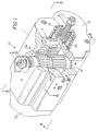
- FIG. 1 shows a partial cutaway view of the long life rack and pinion actuator 10 of the present invention.
- Actuator 10 comprises a housing 11 having an end cap 15 on one end and an end cap 15a on the opposite end.
- a rotatable shaft 16 having an upper and lower set of peripheral teeth 16a thereon.
- a piston extension rack 12a Located in meshing engagement with the teeth 16a is a piston extension rack 12a that extends outward from the face of piston 12.
- a set of springs 13 and 14 provide a stop for piston 12 when the piston is retracted.
- a bolt 20 having a stop end 22 and a nut 21 thereon provides for adjustment of stop end 22 which engages the back side of piston 12. While only one piston is shown in Figure 1 the actuator is symmetrical and includes a second piston on the opposite end of actuator 10.
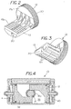
- Figure 2 shows an isolated top side perspective view of piston 12 with piston 12 having a cylindrical skirt 30 and an offset extension 13 that extends from face 12a of piston 12.
- extension 13 Located on extension 13 are a rack of teeth 13a for engaging the teeth 16a on rotateable shaft 16.
- Located on the lower side of extension 13 is a channel vent passage 20 to permit ingress and egress of fluid therethrough.
- Figure 3 shows an isolated bottom side perspective view of piston 12 revealing the channel passage 20 that extends longitudinally along the lower side of extension 13 as well as the integral elongated reinforcement ribs 13b for extensions 13.
- Figure 4 shows a cross sectional view taken along lines 4-4 of Figure 1 showing the piston 12 and piston 32 in engagement with teeth 16a on rotateable shaft 16.
- the piston 32 and piston 12 are identical to each other.
- actuator 10 In operation of actuator 10, if the pressure in piston end chamber 40 and piston end chamber 41 is greater than the pressure in central chamber 35 the pistons 12 and 32 are driven toward each other (indicated by arrows) thereby causing counter clockwise rotation of shaft 16 as the teeth on extension of each of the piston 12 and 32 engage the teeth 16a on the shaft and rotate the shaft 16. Similarly, if the pressure in the central chamber 35 is higher than the pressure in piston end chamber 40 and 41 the pistons are driven away from each other causing clockwise rotation of shaft 16 through engagement with the teeth 16a thereon. Thus through controlling the pressure in piston end chamber 40 and 41 as well as central chamber 35 one can drive pistons 12 and 32 back and forth within the cylindrical sidewalls 11a.
- Figure 5 is a cross sectional view taken along lines 5-5 of Figure 1 showing the piston 12 and 32 in relation to the shaft 16 which is rotateable mounted in housing 11.
- Piston 12 incudes a peripheral sealing and lubrication region 43 and similarly piston 32 includes a peripheral sealing and lubrication region 42.
- FIG. 5a shows the sliding region 42 of piston 32 in greater detail.
- Housing 11 has a cylindrical piston wall surface 11a for piston 32 to slide therealong.
- Recess 32a carries an annular wear member 51 to permit sliding engagement with wall surface 11a.
- recess 32c carries a wear member 52 to permit sliding engagement with wall surface 11a.
- recess 32c carries a resilient sealing member 53, such as an elastomer, to prevent flow therearound as well as resilient hold wear member 52 against wall 11a to allow piston 32 to slide laterally along cylindrical sealing wall 11a.
- the wear members 51 and 52 are made from a rigid wear material such as nylon or the like, which is softer than the cylindrical sealing wall 11a, yet sufficiently durable so as to be able to withstand repeated sliding engagement without having to be replaced.
- annular lubrication recess 32b for carrying a lubricant.
- a solid or viscous lubricant can be placed in the lubrication recess 32b to enable the lubrication to be carried on the piston skirt as the piston 32 slides back and forth thereby enabling the lubricant to be continually available proximate the wear members 51 and 52.
- the lubricant 70 which can be maintained in recess 32b is available for continual lubrication of the surface 11a so as to minimize wear as the piston 32 slides back and forth with the wear members 51 and 53 in sliding engagement with cylindrical wall surface 11a.
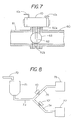
- Figure 6 shows a cross sectional view of actuator 10 showing the channel passage 20 is in fluid communication with a passage 11b in housing wall 11 to permit fluid to escape from the central chamber 35 as the pistons 12 and 32 move back and forth.
- FIG. 7 shows the actuator 10 of the present invention mounted on a rotatable valve such as a disk valve 63 found in a conveying system.
- a first conduit 61 is connected to conduit 60 with a disk valve 63 positioned in the passage.
- a shaft 62 carries disk valve 63 with shaft 62 having a top end 62a for engagement therotateable shaft 16 of the actuator 10.
- the lower end 62b provides for rotational support of the lower end of shaft 16.
- Actuator 10 is provide with fluid ports 10c and 10d which are connected to the chambers within actuator 10 so that the pistons 12 and 32 can be driven back and forth thereby causing rotation of shaft 16a which in turn rotates shaft 62 to open or close the passage from conduit 61 to conduit 62.
- the disk valve 63 is shown positioned in the open postion to allow flow of fluid past either side of disk 63. In order to close off the passage the disk 63 is rotated 90 degrees so that the disk 63 is perpendicular to the conduits 60 and 61.
- Figure 8 shows a system wherein a set of actuators 10 and 10' are connected to disk valves to permit diverting a material in the system.
- material is delivered to hopper 71 though conduit 72. The material then flows into pipe 73 and into branch pipes 74 and 75. If the valve to actuator 10 is in the open condition the material flows into bin 76 but if the valve is in the closed condition material is prevent from flowing into bin 76. Similarly, if the valve attached to actuator 10' is in the open condition the material flows into bin 77 but if the valve is in the closed condition material is prevent from flowing into bin 77.
- the invention includes a method for extending the cycle life of a rack and pinion actuator comprising the steps of forming at least two spaced apart wear member which are carried on a skirt of a piston for forming sliding engagement with a cylinder wall and placing an elastomer member proximate at least one of the spaced apart wear members to prevent flow of fluid therepast as well as to resiliently maintain the at least one of the spaced apart wear members in resilient contact with the cylinder wall.
- a non-runable lubricant such as viscous or solid lubricant between the spaced apart members one can provide for on-the-go lubrication of the wear members.
- the invention thus includes a conveying system with an actuator having a rotatable shaft and a set of pistons slidable in a cylinder, each of the pistons having a set of teeth for engaging with a set of teeth on the rotateable shaft so that displacement of the pistons toward or away from each other produces at least a partial rotation of the rotateable shaft.
- Each of the pistons has a skirt carrying a first wear member, a lubricant and a second wear member located on the skirt.
- an inner resilient or elastomer sealing member for preventing flow of fluidtherepast with lubricant carried therein maintaining a lubricated state between the cylinder and the wear member to allow for repeated displacement of the pistons without having to replace the sealing or the wear member.
Abstract
Description
- This invention relates generally to actuators and more specifically to actuator controlled equipment that requires extended run times before repair or replacement of the actuator.
- None.
- None
- None
- The concept of rack and pinion actuators for converting linear motion into rotational motion is known in the art. One of difficulties with conventional actuators is that the actuators often need to be replaced or repaired due to repeated use. In certain applications the repair or replacement of the actuators needs to be minimized since the whole system may need to be shut down to repair or replace the actuator. Because of the unbalanced arrangement of forces on rack and piston actuators it is often times difficult to obtain an extended operating life for a rack and pinion actuator. The present invention provides a long life actuator that eliminates the need for frequent repair or replacement of the actuators.
- Briefly, the invention comprises an actuator having a set of slidable pistons including sliding regions with the sliding regions including at least one wear member supported by a resilient member. A second wear member can be laterally spaced from the first wear member with a lubricant carried therebetween for maintaining the wear members in lubricated sliding engagement with the cylindrical walls of the housing to limit the need to replace or repair the actuator. In order to provide rapid ingress and egress of fluid from the chambers within the actuator a channel passage extends along the back side of an extension of each of the piston to permit quick venting of fluid.
-
- Figure 1 shows a partial cutaway view of the long life rack and pinion actuator of the present invention;
- Figure 2 shows an isolated top side perspective view of a piston in the actuator of Figure 1;
- Figure 3 shows an isolated bottom side perspective view of a piston in the actuator of Figure 1;
- Figure 4 is a cross sectional view taken along lines 4-4 of Figure 1;
- Figure 5 is a cross sectional view taken along lines 5-5 of Figure 1;
- Figure 5a is an enlarged view of a portion of the sliding region on the piston in the actuator;
- Figure 6 is a sectional view taken along lines 6-6 of Figure 1
- Figure 7 is a conveying systems having the actuator of the present invention controlling a disk valve; and
- Figure 8 is a conveying system utilizing a pair of actuators with a pair of disk valves to control the delivery of material into a set of bins.
-
- Figure 1 shows a partial cutaway view of the long life rack and
pinion actuator 10 of the present invention.Actuator 10 comprises ahousing 11 having anend cap 15 on one end and anend cap 15a on the opposite end. Located centrally and rotationally mounted withinhousing 11 is arotatable shaft 16 having an upper and lower set ofperipheral teeth 16a thereon. Located in meshing engagement with theteeth 16a is apiston extension rack 12a that extends outward from the face ofpiston 12. A set ofsprings piston 12 when the piston is retracted. Abolt 20 having astop end 22 and a nut 21 thereon provides for adjustment ofstop end 22 which engages the back side ofpiston 12. While only one piston is shown in Figure 1 the actuator is symmetrical and includes a second piston on the opposite end ofactuator 10. - Figure 2 shows an isolated top side perspective view of
piston 12 withpiston 12 having acylindrical skirt 30 and anoffset extension 13 that extends fromface 12a ofpiston 12. Located onextension 13 are a rack ofteeth 13a for engaging theteeth 16a onrotateable shaft 16. Located on the lower side ofextension 13 is achannel vent passage 20 to permit ingress and egress of fluid therethrough. As theteeth 13a on the offset extension are also offset from the center of thepiston 12 and theteeth 13a are used to drive therotatable shaft 16a there is an inherent unbalance of forces on the face of the pistons produces unequal forces on the skirt of the piston which carries the sealing members, which can lead to higher wear areas on portions of the skirt of the pistons. - Figure 3 shows an isolated bottom side perspective view of
piston 12 revealing thechannel passage 20 that extends longitudinally along the lower side ofextension 13 as well as the integral elongated reinforcement ribs 13b forextensions 13. - Figure 4 shows a cross sectional view taken along lines 4-4 of Figure 1 showing the
piston 12 andpiston 32 in engagement withteeth 16a onrotateable shaft 16. Thepiston 32 andpiston 12 are identical to each other. - In operation of
actuator 10, if the pressure inpiston end chamber 40 andpiston end chamber 41 is greater than the pressure incentral chamber 35 thepistons shaft 16 as the teeth on extension of each of thepiston teeth 16a on the shaft and rotate theshaft 16. Similarly, if the pressure in thecentral chamber 35 is higher than the pressure inpiston end chamber shaft 16 through engagement with theteeth 16a thereon. Thus through controlling the pressure inpiston end chamber central chamber 35 one can drivepistons - Figure 5 is a cross sectional view taken along lines 5-5 of Figure 1 showing the
piston shaft 16 which is rotateable mounted inhousing 11. Piston 12 incudes a peripheral sealing andlubrication region 43 and similarlypiston 32 includes a peripheral sealing andlubrication region 42. - Figure 5a shows the
sliding region 42 ofpiston 32 in greater detail.Housing 11 has a cylindrical piston wall surface 11a forpiston 32 to slide therealong. Located on the skirt ofpiston 32 are threecircumferential recesses annular wear member 51 to permit sliding engagement with wall surface 11a. Similarly,recess 32c carries awear member 52 to permit sliding engagement with wall surface 11a. In addition recess 32c carries aresilient sealing member 53, such as an elastomer, to prevent flow therearound as well as resilienthold wear member 52 against wall 11a to allowpiston 32 to slide laterally along cylindrical sealing wall 11a. In the embodiment shown thewear members - Located between
recess lubrication recess 32b to enable the lubrication to be carried on the piston skirt as thepiston 32 slides back and forth thereby enabling the lubricant to be continually available proximate thewear members lubricant 70 which can be maintained inrecess 32b is available for continual lubrication of the surface 11a so as to minimize wear as thepiston 32 slides back and forth with thewear members - Figure 6 shows a cross sectional view of
actuator 10 showing thechannel passage 20 is in fluid communication with a passage 11b inhousing wall 11 to permit fluid to escape from thecentral chamber 35 as thepistons - The
actuator 10 of the present invention is useful in many types of systems. Figure 7 shows theactuator 10 of the present invention mounted on a rotatable valve such as adisk valve 63 found in a conveying system. In the embodiment shown afirst conduit 61 is connected toconduit 60 with adisk valve 63 positioned in the passage. Ashaft 62 carriesdisk valve 63 withshaft 62 having atop end 62a for engagementtherotateable shaft 16 of theactuator 10. - The lower end 62b provides for rotational support of the lower end of
shaft 16.Actuator 10 is provide withfluid ports 10c and 10d which are connected to the chambers withinactuator 10 so that thepistons shaft 16a which in turn rotatesshaft 62 to open or close the passage fromconduit 61 to conduit 62. As can be seen in Figure 7 thedisk valve 63 is shown positioned in the open postion to allow flow of fluid past either side ofdisk 63. In order to close off the passage thedisk 63 is rotated 90 degrees so that thedisk 63 is perpendicular to theconduits - Figure 8 shows a system wherein a set of
actuators 10 and 10' are connected to disk valves to permit diverting a material in the system. In the system shown in Figure 8 material is delivered tohopper 71 thoughconduit 72. The material then flows intopipe 73 and intobranch pipes actuator 10 is in the open condition the material flows intobin 76 but if the valve is in the closed condition material is prevent from flowing intobin 76. Similarly, if the valve attached to actuator 10' is in the open condition the material flows intobin 77 but if the valve is in the closed condition material is prevent from flowing intobin 77. - With the combination of the wear members of the present invention and the lubricant reservoir over a million piston cycles are obtainable without having to replace or repair the actuator.
- Thus the invention includes a method for extending the cycle life of a rack and pinion actuator comprising the steps of forming at least two spaced apart wear member which are carried on a skirt of a piston for forming sliding engagement with a cylinder wall and placing an elastomer member proximate at least one of the spaced apart wear members to prevent flow of fluid therepast as well as to resiliently maintain the at least one of the spaced apart wear members in resilient contact with the cylinder wall. In addition by including the step of placing a non-runable lubricant such as viscous or solid lubricant between the spaced apart members one can provide for on-the-go lubrication of the wear members.
- The invention thus includes a conveying system with an actuator having a rotatable shaft and a set of pistons slidable in a cylinder, each of the pistons having a set of teeth for engaging with a set of teeth on the rotateable shaft so that displacement of the pistons toward or away from each other produces at least a partial rotation of the rotateable shaft. Each of the pistons has a skirt carrying a first wear member, a lubricant and a second wear member located on the skirt. Located proximate one of the wear member is an inner resilient or elastomer sealing member for preventing flow of fluidtherepast with lubricant carried therein maintaining a lubricated state between the cylinder and the wear member to allow for repeated displacement of the pistons without having to replace the sealing or the wear member.
- With the lubrication recess extending around the peripheral circumferential region of the skirt of each of the pistons one can and carry a lubricant for 360 degree lubrication of the wear members.
- Where technical features mentioned in any claim are followed by reference signs, those reference signs have been included for the sole purpose of increasing the intelligibility of the claims and accordingly, such reference signs do not have any limiting effect on the scope of each element identified by way of example by such reference signs.
Claims (24)
- A system:an actuator, said actuator having a rotatable shaft and a set of pistons slidable in a cylinder, each of said pistons having a set of teeth for engaging with a set of teeth on the rotateable shaft so that displacement of the pistons toward or away from each other produces at least a partial rotation of the rotateable shaft; each of said set of pistons having a skirt, each of said skirts carrying a first wear member, a lubricant and a sealing member, said sealing member comprising a resilient member for preventing flow of fluidtherepast and for maintain an outer wear member in contact with the cylinder; said lubricant for maintaining an on-the-go lubricated state between the cylinder and the wear member to allow for repeated displacement of said pistons without having to replace the sealing member thereon.
- The system of claim 1 including a conduit and a valve for opening the conduit as the valve is rotated in one direction and for closing the conduit when the valve is rotated in the opposite direction.
- The system of claim 2 wherein the rotatable shaft of said actuator connects to the valve to permit opening and closing of the valve through a linear displacement of said piston.
- The system of claim 1 including a recess on each of said skirts with each of said recess holding a further wear member therein.
- The system of claim 4 including a lubrication recess on each of the skirts which is positioned between the further wear member and the wear member.
- The system of claim 1 wherein the wear member comprises a polymer plastic member.
- The system of claim 1 wherein the wear member and the lubrication carried on said skirt is a sufficient amount of lubricant to permit at least one million displacement cycles of said pistons withoutrelubrication or replacing the wear member.
- The system of claim 1 wherein each of the pistons includes an extension with a rack of teeth thereon.
- The system of claim 1 wherein each of the pistons includes a set of ribs in the extension.
- The system of claim 9 including an elongated channel vent passage extending along each of the extensions to permit venting of air from a central chamber located between said set of pistons.
- The system of claim 1 wherein the lubricant comprises a viscous lubricant.
- A rack and pinion actuator with the rack and pinion actuator having a pair of slidable pistons each having a rack of teeth in engagement with arotateable shaft with the improvement comprising an improved sliding region on a skirt of each of the pistons with the improved sliding region containing a wear member supported in pressure contact adjacent a cylinder wall by a resilient sealing member.
- The rack and pinion actuator of claim 12 including a second wear member located on the skirt of each of the pistons to provide sliding support to the each of the pistons.
- The rack and pinion actuator of claim 13 including a lubrication recess located between the first and second wear members with the lubrication recess extending around the peripheral region of the skirt and carrying a lubricant for 360 degree lubrication of the wear members.
- The rack and pinion actuator of claim 14 wherein each of the wear members are secured in a recess extending circumferentially around each of the skirts of said piston.
- The rack and pinion actuator or claim 15 wherein the resilient sealing member comprises an elastomer ring.
- The rack and pinion actuator or claim 16 wherein each of the pistons includes an extension with a channel passage located along a back side thereof for venting a fluid from a central chamber in the rack and pinion actuator..
- The rack and pinion actuator of claim 17 wherein a rotatable disk valve is connected to a rotatable shaft in the rack and pinion actuator to permit opening and closing of the disk valve when the disk valve is mounted in a conveying system.
- A method for extending the cycle life of a rack and pinion actuator comprising the steps of forming a wear member carryable on a skirt of a piston for forming sliding engagement with a cylinder wall and placing an elastomer member proximate the wear member to prevent flow of fluidtherepast as well as to resiliently maintain the wear members in resilient contact with the cylinder wall.
- The method of claim 19 including the step of placing a non-runable lubricant between the spaced apart members to provide for on-the-go lubrication of the wear members.
- The method of claim 20 including the step of placing a further wear member on each of the skirts of said piston a spaced distance from the wear member on the skirt.
- The method of claim 21 wherein the lubricant is placed between the furtherwear member and the wear member.
- The method of claim 22 wherein the lubricant is positioned in an annular recess in each of the skirts of the piston.
- The method of claim 23 wherein the lubricant is positioned circumferentially around the skirt of each of the pistons.
Applications Claiming Priority (2)
| Application Number | Priority Date | Filing Date | Title |
|---|---|---|---|
| US461892 | 1983-01-28 | ||
| US10/461,892 US6959913B2 (en) | 2003-06-13 | 2003-06-13 | Actuator |
Publications (1)
| Publication Number | Publication Date |
|---|---|
| EP1486680A1 true EP1486680A1 (en) | 2004-12-15 |
Family
ID=33299875
Family Applications (1)
| Application Number | Title | Priority Date | Filing Date |
|---|---|---|---|
| EP20040012893 Withdrawn EP1486680A1 (en) | 2003-06-13 | 2004-06-01 | Actuator |
Country Status (7)
| Country | Link |
|---|---|
| US (2) | US6959913B2 (en) |
| EP (1) | EP1486680A1 (en) |
| JP (1) | JP4723819B2 (en) |
| CN (1) | CN1573131A (en) |
| BR (1) | BRPI0401473A (en) |
| CA (1) | CA2461371C (en) |
| TW (1) | TW200502498A (en) |
Cited By (6)
| Publication number | Priority date | Publication date | Assignee | Title |
|---|---|---|---|---|
| EP2037145A3 (en) * | 2007-09-14 | 2009-07-08 | ZF Friedrichshafen AG | Actuating device |
| EP2385284A1 (en) * | 2010-05-04 | 2011-11-09 | ROTECH Antriebselemente GmbH | Actuating device for a fitting |
| FR2976983A1 (en) * | 2011-06-27 | 2012-12-28 | Ksb Sas | ROTATING QUART ACTUATOR WITH NON-CYLINDRICAL SPROCKET AND ADDITIONAL RACK |
| WO2013068112A1 (en) * | 2011-11-10 | 2013-05-16 | Schwing Gmbh | Boom construction, in particular for a truck-mounted concrete pump, and truck-mounted concrete pump |
| EP3290719A1 (en) * | 2016-08-31 | 2018-03-07 | Goodrich Actuation Systems SAS | Seal arrangement for an actuator |
| IT201900015890A1 (en) * | 2019-09-09 | 2021-03-09 | C G M Srl | TILT DEVICE |
Families Citing this family (11)
| Publication number | Priority date | Publication date | Assignee | Title |
|---|---|---|---|---|
| BRPI1014533B1 (en) * | 2009-04-27 | 2020-10-20 | Emerson Process Management Regulator Technologies, Inc | positioning device set |
| CN103003609A (en) * | 2010-06-17 | 2013-03-27 | 布雷国际有限公司 | Multi-teeth engagement in an actuator piston |
| CN201909093U (en) * | 2010-12-22 | 2011-07-27 | 济南高仕机械制造有限公司 | Compressed air single-action actuator |
| US8747054B2 (en) | 2011-01-24 | 2014-06-10 | United Technologies Corporation | Bearing system for gas turbine engine |
| US9587454B1 (en) * | 2014-01-22 | 2017-03-07 | PacSeal Group, Inc. PacSeal | Modular actuator and hydraulic valve assemblies and control apparatus for oil well blow-out preventers |
| US10487873B2 (en) * | 2014-09-11 | 2019-11-26 | Smc Corporation | Linear guide device and actuator |
| US10267429B2 (en) * | 2015-10-23 | 2019-04-23 | Magna Exteriors Inc. | Plastic injection mold—SVG actuator—internal seal upgrade |
| JP6460063B2 (en) * | 2016-06-30 | 2019-01-30 | トヨタ自動車株式会社 | battery |
| US20190321942A1 (en) * | 2018-04-24 | 2019-10-24 | Cold Jet, Llc | Particle blast apparatus |
| CN112459960B (en) * | 2021-02-02 | 2021-04-13 | 湖南机电职业技术学院 | Hydraulic servo motor |
| CN114352669A (en) * | 2021-12-23 | 2022-04-15 | 中联重科股份有限公司 | Hydro-pneumatic suspension system, rigid and flexible control valve thereof and engineering vehicle |
Citations (5)
| Publication number | Priority date | Publication date | Assignee | Title |
|---|---|---|---|---|
| FR1509067A (en) * | 1966-11-29 | 1968-01-12 | Sud Aviation | Piston for hydraulic accumulator |
| EP0099546A1 (en) * | 1982-07-21 | 1984-02-01 | AVA Steuerungstechnik GmbH | Rotary actuator |
| US4928577A (en) * | 1987-09-17 | 1990-05-29 | Kurt Stoll | Piston and cylinder unit |
| DE4411006A1 (en) * | 1993-06-17 | 1994-12-22 | Festo Kg | Guiding- and sealing-ring combination |
| US6173965B1 (en) * | 1998-12-28 | 2001-01-16 | Leopold J. Niessen | Actuator seal bearing assembly and method |
Family Cites Families (43)
| Publication number | Priority date | Publication date | Assignee | Title |
|---|---|---|---|---|
| US680465A (en) * | 1900-10-19 | 1901-08-13 | George H Reynolds | Piston. |
| JPS455303Y1 (en) * | 1965-06-01 | 1970-03-13 | ||
| DE2103646A1 (en) * | 1971-01-27 | 1972-08-17 | Bosch Gmbh Robert | Working cylinder |
| JPS499947U (en) * | 1972-05-06 | 1974-01-28 | ||
| JPS499947A (en) * | 1972-05-20 | 1974-01-29 | ||
| JPS5099389A (en) * | 1973-12-28 | 1975-08-07 | ||
| JPS5099389U (en) * | 1974-01-19 | 1975-08-18 | ||
| US3994604A (en) * | 1975-06-30 | 1976-11-30 | Clark Equipment Company | Piston and rod connection |
| JPS54106504U (en) * | 1978-01-13 | 1979-07-26 | ||
| JPS54106504A (en) * | 1978-02-09 | 1979-08-21 | Agency Of Ind Science & Technol | System for coal gasification |
| US4214796A (en) * | 1978-10-19 | 1980-07-29 | General Electric Company | Bearing assembly with multiple squeeze film damper apparatus |
| SE414815B (en) * | 1978-11-24 | 1980-08-18 | Wire Matic Regler Ab | PNEUMATIC MANOVERDON |
| JPS5687604A (en) * | 1979-12-05 | 1981-07-16 | Atomic Energy Authority Uk | Particle coating |
| JPS5687604U (en) * | 1979-12-07 | 1981-07-14 | ||
| JPS6128085Y2 (en) * | 1980-02-06 | 1986-08-21 | ||
| JPS56117102A (en) * | 1980-02-20 | 1981-09-14 | Hitachi Ltd | Correcting method of noncontact thickness gauge |
| JPS5966064A (en) * | 1982-10-05 | 1984-04-14 | Matsushita Electric Ind Co Ltd | Manufacture of gas diffusion electrode for battery |
| JPS5966064U (en) * | 1982-10-27 | 1984-05-02 | エヌオーケー株式会社 | Patsuking |
| JPS6015266A (en) * | 1983-07-07 | 1985-01-25 | Atsugi Motor Parts Co Ltd | Rack-pinion type steering gear |
| JPS60121560A (en) * | 1983-12-02 | 1985-06-29 | Matsushita Electric Ind Co Ltd | Magnetic recording and reproducing device |
| JPS60121560U (en) * | 1983-12-22 | 1985-08-16 | 三菱電線工業株式会社 | Sliding packing |
| JPS60139959A (en) * | 1983-12-27 | 1985-07-24 | Honda Motor Co Ltd | Control for automatic speed change gear |
| JPS60139959U (en) * | 1984-02-28 | 1985-09-17 | 三菱電線工業株式会社 | Lube-free packing for sliding |
| JPS61119607A (en) * | 1984-11-16 | 1986-06-06 | Kawasaki Steel Corp | Operating method of blast furnace |
| JPS61119607U (en) * | 1985-01-14 | 1986-07-28 | ||
| DE3534577C2 (en) * | 1985-09-27 | 1993-11-18 | Atsugi Motor Parts Co Ltd | Hydraulic rack and pinion steering |
| JPS63118404A (en) * | 1986-11-04 | 1988-05-23 | シビル環境エンジニヤリング株式会社 | Outdoor sound-absorbing wall construction method |
| JPS63118404U (en) * | 1987-01-26 | 1988-07-30 | ||
| JPS6414903A (en) * | 1987-07-08 | 1989-01-19 | Kanegafuchi Chemical Ind | Resin-bound permanent magnet |
| JPH0712724Y2 (en) * | 1987-07-16 | 1995-03-29 | 株式会社キッツ | Pneumatic actuator |
| US4890645A (en) * | 1987-10-08 | 1990-01-02 | Baroid Technology, Inc. | Rotary shear seal hydraulic valve |
| JPH0292106A (en) * | 1988-09-29 | 1990-03-30 | Nec Corp | Automatic gain control circuit |
| JPH0292106U (en) * | 1989-01-10 | 1990-07-23 | ||
| JPH0369759A (en) * | 1989-08-07 | 1991-03-26 | Sukemasa Umeda | Application of panel to external wall without calking |
| JPH0744852Y2 (en) * | 1989-11-14 | 1995-10-11 | エヌオーケー株式会社 | Packing |
| JPH0434203A (en) * | 1990-05-31 | 1992-02-05 | T V Valve Kk | Piston type oscillatory actuator |
| JPH0452658A (en) * | 1990-06-21 | 1992-02-20 | Toshiba Corp | Image forming device |
| JPH0452658U (en) * | 1990-09-10 | 1992-05-06 | ||
| JP2600562Y2 (en) * | 1992-02-18 | 1999-10-12 | 株式会社ユニシアジェックス | Cylinder device |
| JPH0658288U (en) * | 1993-01-27 | 1994-08-12 | 株式会社千代田製作所 | Compressed air operated valve device |
| JPH08145186A (en) * | 1994-11-18 | 1996-06-04 | Nok Corp | Seal device |
| JP2003278712A (en) * | 2002-01-16 | 2003-10-02 | S N Seiki:Kk | Air type actuator and manufacturing method thereof |
| WO2003106846A1 (en) * | 2002-06-14 | 2003-12-24 | 株式会社キッツ | Pneumatic actuator |
-
2003
- 2003-06-13 US US10/461,892 patent/US6959913B2/en not_active Expired - Lifetime
-
2004
- 2004-03-18 TW TW093107232A patent/TW200502498A/en unknown
- 2004-03-19 CA CA 2461371 patent/CA2461371C/en not_active Expired - Fee Related
- 2004-04-20 BR BRPI0401473 patent/BRPI0401473A/en not_active Application Discontinuation
- 2004-05-12 JP JP2004141813A patent/JP4723819B2/en not_active Expired - Fee Related
- 2004-06-01 CN CNA2004100473571A patent/CN1573131A/en active Pending
- 2004-06-01 EP EP20040012893 patent/EP1486680A1/en not_active Withdrawn
-
2005
- 2005-08-11 US US11/201,589 patent/US7111823B2/en not_active Expired - Lifetime
Patent Citations (5)
| Publication number | Priority date | Publication date | Assignee | Title |
|---|---|---|---|---|
| FR1509067A (en) * | 1966-11-29 | 1968-01-12 | Sud Aviation | Piston for hydraulic accumulator |
| EP0099546A1 (en) * | 1982-07-21 | 1984-02-01 | AVA Steuerungstechnik GmbH | Rotary actuator |
| US4928577A (en) * | 1987-09-17 | 1990-05-29 | Kurt Stoll | Piston and cylinder unit |
| DE4411006A1 (en) * | 1993-06-17 | 1994-12-22 | Festo Kg | Guiding- and sealing-ring combination |
| US6173965B1 (en) * | 1998-12-28 | 2001-01-16 | Leopold J. Niessen | Actuator seal bearing assembly and method |
Cited By (14)
| Publication number | Priority date | Publication date | Assignee | Title |
|---|---|---|---|---|
| EP2037145A3 (en) * | 2007-09-14 | 2009-07-08 | ZF Friedrichshafen AG | Actuating device |
| EP2385284A1 (en) * | 2010-05-04 | 2011-11-09 | ROTECH Antriebselemente GmbH | Actuating device for a fitting |
| FR2976983A1 (en) * | 2011-06-27 | 2012-12-28 | Ksb Sas | ROTATING QUART ACTUATOR WITH NON-CYLINDRICAL SPROCKET AND ADDITIONAL RACK |
| WO2013001173A1 (en) | 2011-06-27 | 2013-01-03 | Ksb S.A.S. | Quarter turn actuator having a non-cylindrical pinion, and complementary rack |
| WO2013068112A1 (en) * | 2011-11-10 | 2013-05-16 | Schwing Gmbh | Boom construction, in particular for a truck-mounted concrete pump, and truck-mounted concrete pump |
| CN103998368A (en) * | 2011-11-10 | 2014-08-20 | 施维英有限公司 | Boom construction, in particular for a truck-mounted concrete pump, and truck-mounted concrete pump |
| EP2776360B1 (en) | 2011-11-10 | 2016-02-03 | Schwing GmbH | Boom construction, in particular for a truck-mounted concrete pump, and truck-mounted concrete pump |
| CN103998368B (en) * | 2011-11-10 | 2016-06-08 | 施维英有限公司 | It is particularly useful for jib structure and the Vehicular concrete pump of Vehicular concrete pump |
| CN105947909A (en) * | 2011-11-10 | 2016-09-21 | 施维英有限公司 | Boom construction and truck-mounted concrete pump |
| US9453351B2 (en) | 2011-11-10 | 2016-09-27 | Schwing Gmbh | Boom construction for a truck-mounted concrete pump |
| EP3290719A1 (en) * | 2016-08-31 | 2018-03-07 | Goodrich Actuation Systems SAS | Seal arrangement for an actuator |
| EP3290719B1 (en) | 2016-08-31 | 2019-07-17 | Goodrich Actuation Systems SAS | Seal arrangement for an actuator |
| IT201900015890A1 (en) * | 2019-09-09 | 2021-03-09 | C G M Srl | TILT DEVICE |
| WO2021048737A1 (en) * | 2019-09-09 | 2021-03-18 | C.G.M. Srl | Tilting device |
Also Published As
| Publication number | Publication date |
|---|---|
| BRPI0401473A (en) | 2005-01-18 |
| TW200502498A (en) | 2005-01-16 |
| US7111823B2 (en) | 2006-09-26 |
| US20040251445A1 (en) | 2004-12-16 |
| CA2461371C (en) | 2011-09-13 |
| CN1573131A (en) | 2005-02-02 |
| JP4723819B2 (en) | 2011-07-13 |
| US6959913B2 (en) | 2005-11-01 |
| US20050274919A1 (en) | 2005-12-15 |
| CA2461371A1 (en) | 2004-12-13 |
| JP2005003196A (en) | 2005-01-06 |
Similar Documents
| Publication | Publication Date | Title |
|---|---|---|
| US7111823B2 (en) | Actuator | |
| CN2777241Y (en) | Coupled reciprocating movement diaphragm pump with linkage axle | |
| RU2717590C2 (en) | Compressed gas sealing system for control valves | |
| CA2509996C (en) | Valve apparatus and pneumatically driven diaphragm pump incorporating same | |
| US7694939B2 (en) | Flow rate control valve | |
| JP5662950B2 (en) | Gate valve with lubricated secondary seal | |
| US9631731B2 (en) | Diverter valve | |
| CN105074217A (en) | Vane pump with multiple control chambers | |
| CA2019839C (en) | Air/oil level control for transmission lubrication | |
| US6142181A (en) | 3/3-way valve | |
| CN100498027C (en) | Seal for a valve | |
| CN1302964A (en) | Two way selected valve | |
| US20080106045A1 (en) | Decoupled shaft seal for a progressive cavity pump stuffing box | |
| CN108331792A (en) | Control has the hydraulic module and connecting rod of the hydraulic fluid stream of the connecting rod of the internal combustion engine of variable compression ratio | |
| KR19980087396A (en) | Aerator Valve Assembly | |
| US11965597B2 (en) | Piston assembly, air cylinder and apparatus for processing substrate | |
| US11536375B2 (en) | Valve seat with seal for use with valve element in valve assembly | |
| US6981854B1 (en) | Small piston pump | |
| US637487A (en) | Annular slide-valve. | |
| US20040184939A1 (en) | Feed pump | |
| KR20050039797A (en) | Airless pump's packing | |
| CN1806140A (en) | Stepper motor driven valve | |
| GB2055974A (en) | Rotary positive-displacement fluid-machines | |
| KR20050100163A (en) | Structure of valve | |
| CA2608674A1 (en) | Decoupled shaft seal for a progressive cavity pump stuffing box |
Legal Events
| Date | Code | Title | Description |
|---|---|---|---|
| PUAI | Public reference made under article 153(3) epc to a published international application that has entered the european phase |
Free format text: ORIGINAL CODE: 0009012 |
|
| AK | Designated contracting states |
Kind code of ref document: A1 Designated state(s): AT BE BG CH CY CZ DE DK EE ES FI FR GB GR HU IE IT LI LU MC NL PL PT RO SE SI SK TR |
|
| AX | Request for extension of the european patent |
Extension state: AL HR LT LV MK |
|
| 17P | Request for examination filed |
Effective date: 20050504 |
|
| 17Q | First examination report despatched |
Effective date: 20050620 |
|
| AKX | Designation fees paid |
Designated state(s): AT BE BG CH CY CZ DE DK EE ES FI FR GB GR HU IE IT LI LU MC NL PL PT RO SE SI SK TR |
|
| GRAP | Despatch of communication of intention to grant a patent |
Free format text: ORIGINAL CODE: EPIDOSNIGR1 |
|
| STAA | Information on the status of an ep patent application or granted ep patent |
Free format text: STATUS: THE APPLICATION IS DEEMED TO BE WITHDRAWN |
|
| 18D | Application deemed to be withdrawn |
Effective date: 20070116 |