EP1571365A1 - Clutch plate, friction clutch, and coupling device - Google Patents
Clutch plate, friction clutch, and coupling device Download PDFInfo
- Publication number
- EP1571365A1 EP1571365A1 EP05012564A EP05012564A EP1571365A1 EP 1571365 A1 EP1571365 A1 EP 1571365A1 EP 05012564 A EP05012564 A EP 05012564A EP 05012564 A EP05012564 A EP 05012564A EP 1571365 A1 EP1571365 A1 EP 1571365A1
- Authority
- EP
- European Patent Office
- Prior art keywords
- clutch
- friction
- carbon film
- coupling device
- thin carbon
- Prior art date
- Legal status (The legal status is an assumption and is not a legal conclusion. Google has not performed a legal analysis and makes no representation as to the accuracy of the status listed.)
- Granted
Links
Images


Classifications
-
- F—MECHANICAL ENGINEERING; LIGHTING; HEATING; WEAPONS; BLASTING
- F16—ENGINEERING ELEMENTS AND UNITS; GENERAL MEASURES FOR PRODUCING AND MAINTAINING EFFECTIVE FUNCTIONING OF MACHINES OR INSTALLATIONS; THERMAL INSULATION IN GENERAL
- F16D—COUPLINGS FOR TRANSMITTING ROTATION; CLUTCHES; BRAKES
- F16D13/00—Friction clutches
- F16D13/58—Details
- F16D13/60—Clutching elements
- F16D13/64—Clutch-plates; Clutch-lamellae
- F16D13/648—Clutch-plates; Clutch-lamellae for clutches with multiple lamellae
-
- F—MECHANICAL ENGINEERING; LIGHTING; HEATING; WEAPONS; BLASTING
- F16—ENGINEERING ELEMENTS AND UNITS; GENERAL MEASURES FOR PRODUCING AND MAINTAINING EFFECTIVE FUNCTIONING OF MACHINES OR INSTALLATIONS; THERMAL INSULATION IN GENERAL
- F16D—COUPLINGS FOR TRANSMITTING ROTATION; CLUTCHES; BRAKES
- F16D23/00—Details of mechanically-actuated clutches not specific for one distinct type
- F16D23/12—Mechanical clutch-actuating mechanisms arranged outside the clutch as such
-
- F—MECHANICAL ENGINEERING; LIGHTING; HEATING; WEAPONS; BLASTING
- F16—ENGINEERING ELEMENTS AND UNITS; GENERAL MEASURES FOR PRODUCING AND MAINTAINING EFFECTIVE FUNCTIONING OF MACHINES OR INSTALLATIONS; THERMAL INSULATION IN GENERAL
- F16D—COUPLINGS FOR TRANSMITTING ROTATION; CLUTCHES; BRAKES
- F16D27/00—Magnetically- or electrically- actuated clutches; Control or electric circuits therefor
- F16D27/10—Magnetically- or electrically- actuated clutches; Control or electric circuits therefor with an electromagnet not rotating with a clutching member, i.e. without collecting rings
- F16D27/108—Magnetically- or electrically- actuated clutches; Control or electric circuits therefor with an electromagnet not rotating with a clutching member, i.e. without collecting rings with axially movable clutching members
- F16D27/112—Magnetically- or electrically- actuated clutches; Control or electric circuits therefor with an electromagnet not rotating with a clutching member, i.e. without collecting rings with axially movable clutching members with flat friction surfaces, e.g. discs
- F16D27/115—Magnetically- or electrically- actuated clutches; Control or electric circuits therefor with an electromagnet not rotating with a clutching member, i.e. without collecting rings with axially movable clutching members with flat friction surfaces, e.g. discs with more than two discs, e.g. multiple lamellae
-
- F—MECHANICAL ENGINEERING; LIGHTING; HEATING; WEAPONS; BLASTING
- F16—ENGINEERING ELEMENTS AND UNITS; GENERAL MEASURES FOR PRODUCING AND MAINTAINING EFFECTIVE FUNCTIONING OF MACHINES OR INSTALLATIONS; THERMAL INSULATION IN GENERAL
- F16D—COUPLINGS FOR TRANSMITTING ROTATION; CLUTCHES; BRAKES
- F16D23/00—Details of mechanically-actuated clutches not specific for one distinct type
- F16D23/12—Mechanical clutch-actuating mechanisms arranged outside the clutch as such
- F16D2023/123—Clutch actuation by cams, ramps or ball-screw mechanisms
-
- F—MECHANICAL ENGINEERING; LIGHTING; HEATING; WEAPONS; BLASTING
- F16—ENGINEERING ELEMENTS AND UNITS; GENERAL MEASURES FOR PRODUCING AND MAINTAINING EFFECTIVE FUNCTIONING OF MACHINES OR INSTALLATIONS; THERMAL INSULATION IN GENERAL
- F16D—COUPLINGS FOR TRANSMITTING ROTATION; CLUTCHES; BRAKES
- F16D27/00—Magnetically- or electrically- actuated clutches; Control or electric circuits therefor
- F16D2027/008—Details relating to the magnetic circuit, or to the shape of the clutch parts to achieve a certain magnetic path
-
- F—MECHANICAL ENGINEERING; LIGHTING; HEATING; WEAPONS; BLASTING
- F16—ENGINEERING ELEMENTS AND UNITS; GENERAL MEASURES FOR PRODUCING AND MAINTAINING EFFECTIVE FUNCTIONING OF MACHINES OR INSTALLATIONS; THERMAL INSULATION IN GENERAL
- F16D—COUPLINGS FOR TRANSMITTING ROTATION; CLUTCHES; BRAKES
- F16D69/00—Friction linings; Attachment thereof; Selection of coacting friction substances or surfaces
- F16D2069/004—Profiled friction surfaces, e.g. grooves, dimples
-
- F—MECHANICAL ENGINEERING; LIGHTING; HEATING; WEAPONS; BLASTING
- F16—ENGINEERING ELEMENTS AND UNITS; GENERAL MEASURES FOR PRODUCING AND MAINTAINING EFFECTIVE FUNCTIONING OF MACHINES OR INSTALLATIONS; THERMAL INSULATION IN GENERAL
- F16D—COUPLINGS FOR TRANSMITTING ROTATION; CLUTCHES; BRAKES
- F16D2250/00—Manufacturing; Assembly
- F16D2250/0038—Surface treatment
- F16D2250/0046—Coating
-
- F—MECHANICAL ENGINEERING; LIGHTING; HEATING; WEAPONS; BLASTING
- F16—ENGINEERING ELEMENTS AND UNITS; GENERAL MEASURES FOR PRODUCING AND MAINTAINING EFFECTIVE FUNCTIONING OF MACHINES OR INSTALLATIONS; THERMAL INSULATION IN GENERAL
- F16D—COUPLINGS FOR TRANSMITTING ROTATION; CLUTCHES; BRAKES
- F16D2300/00—Special features for couplings or clutches
- F16D2300/06—Lubrication details not provided for in group F16D13/74
-
- F—MECHANICAL ENGINEERING; LIGHTING; HEATING; WEAPONS; BLASTING
- F16—ENGINEERING ELEMENTS AND UNITS; GENERAL MEASURES FOR PRODUCING AND MAINTAINING EFFECTIVE FUNCTIONING OF MACHINES OR INSTALLATIONS; THERMAL INSULATION IN GENERAL
- F16D—COUPLINGS FOR TRANSMITTING ROTATION; CLUTCHES; BRAKES
- F16D2300/00—Special features for couplings or clutches
- F16D2300/10—Surface characteristics; Details related to material surfaces
-
- F—MECHANICAL ENGINEERING; LIGHTING; HEATING; WEAPONS; BLASTING
- F16—ENGINEERING ELEMENTS AND UNITS; GENERAL MEASURES FOR PRODUCING AND MAINTAINING EFFECTIVE FUNCTIONING OF MACHINES OR INSTALLATIONS; THERMAL INSULATION IN GENERAL
- F16D—COUPLINGS FOR TRANSMITTING ROTATION; CLUTCHES; BRAKES
- F16D27/00—Magnetically- or electrically- actuated clutches; Control or electric circuits therefor
- F16D27/004—Magnetically- or electrically- actuated clutches; Control or electric circuits therefor with permanent magnets combined with electromagnets
Definitions
- the present invention relates Lo a friction clutch used in, for example, a coupling device of a vehicle.
- a typical friction clutch includes a drive clutch plate and a driven clutch plate which friction-engage with each other to transmit power.
- the surface treatment is applied onto sliding surfaces of both clutch plates to retard wear by friction.
- the surface treatment includes, for example, nitride treatment, or quenching and tempering treatment. Wear of the sliding surfaces is reduced by reinforcing the sliding surfaces of both clutch plates by these surface treatments.
- An object of the present invention is to provide a clutch plate that is resistant to wear and excellent in durability. Another object of the present invention is to provide a friction clutch and a coupling device that have such clutch plates.
- an iron clutch plate having a sliding surface that contacts another clutch plate is provided.
- a thin carbon film in a diamond form is formed on the sliding surface.
- a friction clutch having a first clutch plate and a second clutch plate.
- the first clutch plate has a first sliding surface.
- the second clutch plate has a second sliding surface that contacts the first sliding surface.
- the clutch plates friction-engage with each other to transmit torque.
- a thin carbon film in a diamond form is formed on at least one of the first and second sliding surfaces.
- a coupling device having a first rotary member, a second rotary member, a plurality of housing chambers, a first clutch, a second clutch, and an electromagnetic actuator.
- the second rotary member is rotatable relative to the first rotary member.
- the housing chambers are defined between the first rotary member and the second rotary member.
- the housing chambers include a first housing chamber, which is not charged with lubricant oil, and a second housing chamber, which is charged with lubricant oil.
- the second housing chamber is sealed from the first housing chamber.
- the first clutch is housed in the first housing chamber.
- the first clutch includes a first iron clutch plate and a second iron clutch plate, which friction-engage with each other.
- the first clutch plate has a first sliding surface that contacts the second clutch plate.
- the second clutch plate has a second sliding surface that contacts the first clutch plate.
- a thin carbon film in a diamond form is formed on at least one of the first and second sliding surfaces.
- the second clutch is housed in the second housing chamber. The first and second clutches cooperate to transmit torque between the first rotary member and the second rotary member.
- the electromagnetic actuator actuates the first clutch such that the clutch plates friction-engage with each other.
- a coupling device having a first rotary member, a second rotary member, a housing chamber, and a plurality of clutches.
- the second rotary member is rotatable relative to the first rotary member.
- the housing chamber is defined between the first rotary member and the second rotary member.
- the housing chamber is charged with lubricant oil.
- the clutches are located in the housing chamber.
- the clutches cooperate to transmit torque between the first rotary member and the second rotary member.
- At least one of the clutches is a friction clutch having a first iron clutch plate and a second clutch plate.
- the clutch plates friction-engage with each other.
- the first clutch plate has a first sliding surface that contacts the second clutch plate.
- the second clutch plate has a second sliding surface that contacts the first clutch plate.
- a thin carbon film in a diamond form is formed on at least one of the first and second sliding surfaces.
- a four-wheel drive vehicle 12 includes a coupling device 11, a trans-axle 13, an engine 14, a pair of front wheels 15, and a pair of rear wheels 16. Power of the engine 14 is transmitted to the front wheels 15 via the trans-axle 13 and a pair of axle shafts 17.
- the coupling device 11 is provided on a power transmission route between the engine 14 and the rear wheels 16. Namely, the coupling device 11 is connected to the trans-axle 13 via a propeller shaft 18. A rear differential 20 is connected to the coupling device 11 via a drive pinion shaft 19. The rear wheels 16 are connected to the rear differential 20 via a pair of axle shafts 21. The coupling device 11 selectively permits and shuts off the transmission of torque from the propeller shaft 18 to the drive pinion shaft 19.
- the coupling device 11 and the rear differential 20 are housed in a differential carrier 22 and are supported by the carrier 22.
- the differential carrier 22 is supported by a vehicle body of the four-wheel drive vehicle 12.
- the coupling device 11 includes a first rotary member, a second rotary member, a second clutch, a pilot clutch mechanism 30d, and a cam mechanism 30e.
- the first rotary member is an outer case 30a
- the second rotary member is an inner shaft 30b
- the second clutch is a main clutch mechanism 30c.
- the outer case 30a (an external rotary member) includes a closed-end cylindrical front housing 31a and a rear housing 31b screwed into the front housing 31a so as to be placed over a rear end opening part of the front housing 31a.
- An input shaft 50 protrudes from a front end of the front housing 31a.
- the input shaft 50 is connected to the propeller shaft 18 (see Fig. 2).
- the front housing 31a is formed of aluminum (a non-magnetic material), and the rear housing 31b is formed of iron (a magnetic material).
- a ring body 51 of stainless steel (a non-magnetic material) is embedded in a middle part of the rear housing 31b in the radial direction.
- An outer circumference part of the front housing 31a in the vicinity of the front end is supported rotatably with respect to the differential carrier 22 (see Fig. 2) via a bearing (not shown).
- the rear housing 31b is supported rotatably with respect to a yoke 36, which is supported by the differential carrier 22 (see Fig. 2), via a bearing.
- a rear side cylindrical part of the rear housing 31b is supported rotatably with respect to the differential carrier 22 (see Fig. 2) via an oil seal (not shown).
- the inner shaft 30b penetrates through a central part of the rear housing 31b to be inserted into the front housing 31a. A gap between the inner shaft 30b and the rear housing 31b is sealed.
- the inner shaft 30b is supported rotatably with respect to the front housing 31a and the rear housing 31b with its movement in the axial direction being restricted.
- a tip end portion of the drive pinion shaft 19 (see Fig. 2) is fitted into the inner shaft 30 b.
- the drive pinion shaft 19 is not shown in Fig. 1.
- the main clutch mechanism 30c is a wet type clutch mechanism, and includes a plurality of iron inner clutch plates 32a and a plurality of iron outer clutch plates 32b.
- a wet type friction material with cellulosic fibers as a base material is stuck on both side surfaces (both sliding surfaces) of each of the inner clutch plates 32a. Consequently, when the adjacent inner clutch plate 32a and outer clutch plate 32b are engaged with each other, the materials of the plates 32a and 32b, namely, the iron materials are not directly in sliding contact with each other. Thus, particles caused by wear of iron hardly occur.
- clutch plates 32a and 32b are placed near a back wall of the front housing 31a.
- the inner clutch plates 32a are mounted to an outer circumference of the inner shaft 30b by spline fitting, and are movable in the axial direction with respect to the inner shaft 30b.
- the outer clutch plates 32b are mounted to an inner circumference of the front housing 31a by spline fitting, and are movable in the axial direction with respect to the front housing 31a.
- the inner clutch plates 32a and the outer clutch plates 32b are alternately placed.
- the adjacent inner clutch plate 32a and outer clutch plate 32b are capable of moving closer to each other and away from each other in the axial direction.
- the pilot clutch mechanism 30d includes an annular electromagnet 33, a first clutch, and an armature 35.
- the first clutch is a friction clutch 34.
- the electromagnet 33 and armature 35 construct an electromagnetic actuator.
- the electromagnet 33 is fitted in the yoke 36. Part of the yoke 36 and the electromagnet 33 are housed in an annular recess 53 formed in the rear housing 31b.
- the friction clutch 34 includes a plurality of first clutch plates and a plurality of second clutch plates.
- the second clutch plates are iron inner clutch plates 34a
- the first clutch plates are iron outer clutch plates 34b.
- the inner clutch plates 34a are mounted to an outer circumference of a first cam member 37 constructing part of the cam mechanism 30e by spline fitting, and are movable in the axial direction with respect to the first cam member 37.
- the outer clutch plates 34b are mounted to the inner circumference of the front housing 31a by spline fitting, and are movable in the axial direction with respect to the front housing 31a.
- the inner clutch plates 34a and the outer clutch plates 34b are alternately placed.
- the adjacent inner clutch plate 34a and outer clutch plate 34b are able to move close to and away from each other in the axial direction.
- each inner clutch plate 34a has a pair of sliding surfaces 51 opposing two of the outer clutch plates 34b placed at both sides of the plate 34a.
- Each of the two outer clutch plates 34b located at the outermost side has one sliding surface S2 corresponding to the adjacent inner clutch plate 34a.
- Each of the other outer clutch plates 34b has a pair of sliding surfaces S2 opposing two of the inner clutch plates 34a placed at both sides of the plate 34b.
- annular grooves 40 having very small width are formed with a very small pitch on each of the sliding surfaces S1 by press working.
- Known nitride treatment, or known quenching and tempering treatment is applied to each of the sliding surfaces S1.
- these annular grooves 40 are illustrated to be larger than as they are for purposes of illustration, the actual pitch and height of the groove 40 is only several ⁇ m.
- a thin carbon film D in a diamond form is formed on each of the sliding surfaces S2 by a known method such as the CVD (Chemical Vapor Deposition) method, the PVD (Physical Vapor Deposition) method, and the ion vapor deposition method.
- CVD Chemical Vapor Deposition
- PVD Physical Vapor Deposition
- the thin carbon film D in a diamond form is formed by, for example, a forming device 61 shown in Fig. 8.
- the forming device 61 is for performing high temperature plasma CVD, and includes a forming chamber 63 having an exhaust port 62.
- a cathode 64 and an anode 65 for electric discharge are placed inside the forming chamber 63.
- a power supply 66 for applying DC voltage is connected to the cathode 64 and the anode 65.
- a supply port 67 is formed at a tip end of the anode 65.
- Raw material gas for synthesizing the thin carbon film D in a diamond form passes through a space between the cathode 64 and the anode 65, and supplied into the forming chamber 63 from the supply port 67.
- the raw material gas is decomposed and excited by the electric discharge between the cathode 64 and the anode 65, and generates plasma while passing near the supply port 67.
- the inside of the forming chamber 63 is at lower pressure than atmospheric pressure during the period of time from generation of the plasma to forming of the thin carbon film D in a diamond form.
- a holder 68 to set the outer clutch plate 34b is placed inside the forming chamber 63.
- the plasma is applied to the sliding surface S2 of the outer clutch plate 34b set on the holder 68, whereby the thin carbon film D in a diamond form is deposited on a surface of the sliding surface S2 until it has predetermined thickness.
- the thickness of the thin carbon film D in a diamond form is 3 ⁇ m.
- the thickness of the thin carbon film D in a diamond form is in the range of 0.1 to 10 ⁇ m, preferably in the range of 1 to 5 ⁇ m in order to protect each of the sliding surfaces S2 effectively. With the thickness less than 0.1 ⁇ m, useful life against wear is short, and is not suitable for practical use. On the other hand, if the thickness exceeds 10 ⁇ m, the thin carbon film D in a diamond form becomes brittle.
- the thin carbon film D in a diamond form is formed by diamond-like carbon (DLC).
- the armature 35 forming a ring shape is mounted to the inner circumference of the front housing 31a by spline fitting, and is movable in the axial direction with respect to the front housing 31a.
- the armature 35 is located at one side of the friction clutch 34, and opposes the friction clutch 34.
- the electromagnet 33 forms a magnetic path L1 circulating through the yoke 36, the rear housing 31b, the first cam member 37, the armature 35, the friction clutch 34, the rear housing 31b and the yoke 36 when electric current is supplied.
- the cam mechanism 30e includes the first cam member 37, a second cam member 38 and a plurality of ball-shaped cam follower 39.
- the first cam member 37 and the second cam member 38 form substantially a disk shape.
- the first cam member 37 is rotatably fitted onto the outer circumference of the inner shaft 30b, and is supported rotatably with respect to the rear housing 31b via a thrust bearing 41.
- An inner circumference surface of the armature 35 abuts against an outer circumference surface of the first cam member 37.
- the first cam member 37 and the armature 35 are relatively rotatable.
- annular housing groove 42a is formed in an inner circumference surface of the first cam member 37.
- a seal member, or a seal ring 42b contacts the outer circumference surface of the inner shaft 30b and is housed inside the housing groove 42a.
- the seal ring 42b seals a gap between the inner shaft 30b and the first cam member 37.
- An annular housing groove 43a is formed in the inner circumference surface of the armature 35.
- a seal member, or seal ring 43b contacts the outer circumference surface of the first cam member 37 and is housed in the housing groove 43a.
- the seal ring 43b seals a gap between the first cam member 37 and the armature 35.
- An annular housing groove 44a is formed in an outer circumference surface of the armature 35.
- a seal member, or a seal ring 44b, contacts the inner circumference surface of the front housing 31a is housed in the housing groove 44a.
- the seal ring 44b seals a gap between the armature 35 and the front housing 31a.
- a space enclosed by the front housing 31a, the armature 35, the first cam member 37 and the inner shaft 30b forms a first housing chamber K1.
- a space enclosed by the inner shaft 30b, the first cam member 37, the armature 35, the front housing 31a and the rear housing 31b forms a second housing chamber K2.
- the second cam member 38 is mounted to the outer circumference of Lhe inner shaft 30b by spline fitting and is movable in the axial direction with respect to the inner shaft 30b, and rotates integrally with the inner shaft 30b.
- the second cam member 38 opposes the main clutch mechanism 30c.
- the first cam member 37 has a plurality of cam grooves which are placed on the same circle and each placed Lo be spaced by a predetermined angle, on the surface opposing the second cam member 38.
- the second cam member 38 similarly has a plurality of cam grooves which are placed on the same circle and each placed to be spaced by a predetermined angle, on the surface opposing the first cam member 37.
- Each of the cam followers 39 is placed between the cam members 37 and 38, and is held by one of the cam grooves on the first cam member 37 and the corresponding cam groove on the second cam member 38.
- Each cam followers 39 allows relative rotation of both the cam members 37 and 38 only within the range of the circumferential length of both of the corresponding cam grooves.
- Each of the cam followers 39 presses the second cam member 38 in a direction to move away from the first cam member 37, namely, in a direction toward the main clutch mechanism 30c by the action of both the corresponding cam grooves following the relative rotation of both the cam members 37 and 38.
- the armature 35 and the electromagnet 33 are placed to sandwich the friction clutch 34 and the rear housing 31b between them.
- the rear housing 31b functions as a magnet path forming member.
- Lubricant oil to lubricate the clutch plates 32a and 32b is charged in the first housing chamber K1.
- the amount of the lubricant oil inside the first housing chamber K1 is equal to about 80% of the volumetric capacity of the first housing chamber K1.
- the seal mechanism I prevents the lubricant oil inside the first housing chamber K1 from leaking into the second housing chamber K2. While the first housing chamber K1 is the charging space for the lubricant oil, the second housing chamber K2 is the uncharged space for the lubricant oil. Thrust bearing 41 located inside the second housing chamber K2 is lubricated with grease.
- the main clutch mechanism 30c is in a non-engaging state in which the torque transmission to the inner shaft 30b from the front housing 31a is shut, off, and the power of the engine 14 is not transmitted to both the rear wheels 16. Accordingly, the four-wheel drive vehicle 12 is driven in a two-wheel drive mode in which only both the front wheels 15 are driven by the engine 14.
- the friction clutch 34 is held by the rear housing 31b and the armature 35, and both the adjacent clutch plates 34a and 34b are engaged by friction with each other (the engaging state of the friction clutch 34).
- the friction clutch 34 allows torque transmission to the first cam member 37 from the front housing 31a, and the first cam member 37 rotates with the front housing 31a.
- relative rotation occurs between the first cam member 37 and the second cam member 38, and the cam mechanism 30e functions to press the second cam member 38 in the direction toward the main clutch mechanism 30c.
- both the adjacent clutch plates 32a and 32b are engaged with each other by friction and the main clutch mechanism 30c is in the engaging state which allows the torque transmission from the front housing 31a to the inner shaft 30b. Accordingly, the power of the engine 14 is transmitted to both the rear wheels 16 and the four-wheel drive vehicle 12 is driven in a four-wheel drive mode.
- the torque transmission rate from the front housing 31a to the inner shaft 30b is determined according to the electromagnetic attraction force occurring between the electromagnet 33 and the armature 35, in other words, the frictional force between both the adjacent clutch plates 34a and 34b in the friction clutch 34.
- the electromagnetic attraction force can be adjusted by controlling the applied current to the electromagnet 33.
- the electromagnetic attraction force occurring between the electromagnet 33 and the armature 35 increases to the extent which does not allow the friction clutch 34 to slide.
- the cam mechanism 30e increases the force to press the second cam member 38 in the direction to move to the main clutch mechanism 30c, so that slide does not occur to the main clutch mechanism 30c. Accordingly, the outer case 30a and the inner shaft 30b are integrally rotated, and the torque transmission rate from the outer case 30a to the inner shaft 30b becomes 100%. Consequently, the power of the engine 14 is equally transmitted to the front wheels 15 and the rear wheels 16.
- the conventional device does not include the seal rings 42b, 43b and 44b which are included in the device 11 of this embodiment. Therefore, in the conventional device, the gap between the first housing chamber K1 and the second housing chamber K2 is not sealed, and lubricant oil is movable between both the housing chambers K1 and K2. Further, in the conventional device, the lubricant oil of the amount corresponding to 80% of the total volumetric capacity of both the housing chambers K1 and K2 is charged in both the housing chambers K1 and K2. Accordingly, the friction clutch of the conventional device is exposed to the lubricant oil.
- the thin carbon film D in a diamond form is not applied to each of the outer clutch plates in the friction clutch, and instead, nitride treatment or quenching and tempering treatment is applied thereto.
- the torque transmission ability of the conventional device is assumed to be the same as that of the device 11 of this embodiment.
- Fig. 6 is a graph showing relationship between the rotational frequency of the inner shaft (corresponding to the inner shaft 30b of this embodiment) and the drag torque in the conventional device.
- the graph in Fig. 6 is the experimental result which is obtained by rotating the inner shaft in the state in which the outer case (corresponding to the outer case 30a in this embodiment) is fixed in the environment at minus 20 degrees centigrade.
- This graph shows the result of measuring the drag torque which is transmitted from the inner shaft to the outer case by the influence of the viscosity of the lubricant oil and the residual magnetism of the electromagnet in the state in which the electromagnet (corresponding to the electromagnet 33 in this embodiment) is not energized.
- the line a in the graph represents the drag torque occurring as a result that the viscosity of the lubricant oil having influence on the main clutch mechanism (corresponding to the main clutch mechanism 30c in this embodiment).
- the line b in the graph represents the sum of the drag torque shown by the line a, and the drag torque occurring as a result that the residual magnetism of the electromagnet has the influence on the friction clutch (corresponding to the friction clutch 34 in this embodiment).
- the line c in the graph represents the sum of the drag torque shown by the line b, and the drag torque occurring as a result that the viscosity of the lubricant oil has the influence on the friction clutch.
- the drag torque which is caused by the viscosity of the lubricant oil exerted on the main clutch mechanism
- torque A the drag torque, which is caused by the residual magnetism of the electromagnet exerted on the friction clutch
- torque B the drag torque, which is caused by the residual magnetism of the electromagnet exerted on the friction clutch
- torque C the drag torque, which is caused by the viscosity of the lubricant oil exerted on the friction clutch
- the torque C is larger as compared with the torque A and the torque B.
- the reason why the torque C is the largest is that the influence of the viscosity of the lubricant oil exerted on the friction clutch has on the main clutch mechanism after it is amplified by the cam mechanism (corresponding to the cam mechanism 30e of this embodiment).
- the lubricant oil does not exist in the second housing chamber K2 in which the friction clutch 34 is housed, thus exerting no influence of the viscosity of the lubricant oil on the friction clutch 34, and therefore the torque C does not occur. Accordingly, as shown in Fig. 7, when the rotational frequency of the inner shaft is 200 min -1 in the environment at -20 degrees centigrade, the drag torque is reduced by about 82% in the device 11 of this embodiment as compared with the conventional device.
- the friction clutch of the conventional device the nitride treatment or the quenching and tempering treatment is applied to the outer clutch plates and the inner clutch plates. Consequently, when the outer clutch plates and the inner clutch plates are engaged by friction in the state without lubricant oil, vigorous wearing occurs.
- the thin carbon film D in the diamond form is applied to the sliding surfaces S2 of the outer clutch plates 34b, and therefore the sliding surfaces S2 are resistant to wear.
- the thin carbon film D in the diamond form also functions as a solid lubricant, and therefore the sliding surfaces S1 of the inner clutch plates 34a in sliding contact with the sliding surfaces S2 hardly wear. Accordingly, the friction clutch 34 of this embodiment is excellent in durability.
- the device 11 of this embodiment in which the drag torque is decreased dramatically, is excellent in useful life, as compared with the conventional device.
- the drag torque caused by the viscosity of the lubricant oil is increased.
- the friction clutch 34 is not exposed to the lubricant oil, the influence of the drag torque caused by the temperature of the environment is eliminated as much as possible.
- annular grooves 40 provided in both the sliding surfaces S1 of each of the inner clutch plates 34a make it easy to adjust the contact area between the inner clutch plate 34a and the outer clutch plate 34b to be an optional value.
- FIG. 9 to Fig. 12 A second embodiment of the present invention will be explained below with reference to Fig. 9 to Fig. 12 with particular emphasis on a difference from the first embodiment in Fig. 1 to Fig. 8.
- the same components as in the first embodiment shown in Fig. 1 to Fig. 8 are given the reference numerals with 100 being added to the reference numerals given the corresponding components of the first embodiment.
- the first housing chamber K1 in which the lubricant oil exists is sealed from the second housing chamber K2 in which the lubricant oil does not exist.
- the main clutch mechanism 30c is housed in the first housing chamber K1 and the friction clutch 34 is housed in the second housing chamber K2.
- a main clutch mechanism 130c and a friction clutch 134 are both exposed to the lubricant oil.
- the housing grooves 42a, 43a and 44a and the seal rings 42b, 43b and 44h included in the device 11 in Fig. 1 are omitted, and the first housing chamber K1 and the second housing chamber K2 which are separated from each other do not exist.
- An outer circumference surface of a first cam member 137 is a little separated from an inner circumference surface of an armature 135.
- the lubricant oil is charged in a single housing chamber enclosed by an outer case 130a, an inner shaft 130b, and a rear housing 131b.
- the lubricant oil lubricates inner and outer clutch plates 132a and 132b of the main clutch mechanism 130c, and an inner clutch plate 134a and outer clutch plates 134b of the friction clutch 134.
- the friction clutch 134 includes one iron inner clutch plate 134a and two iron outer clutch plates 134b which are placed at both sides of the inner clutch plate 134a.
- an electromagnet 133 When an electric current is supplied to the electromagnetic coil, an electromagnet 133 forms a magnetic path L2 circulating through a yoke 136, a rear housing 131b, the friction clutch 134, an armature 135, the friction clutch 134, the rear housing 131b and the yoke 136.
- a number of grooves M in a substantially net form are formed by press working on both the sliding surfaces S2 of the each outer clutch plate 134b.
- the grooves M receive excessive lubricant oil existing between the inner clutch plate 134a and each of the outer clutch plates 134b opposing it.
- Both the sliding surfaces S1 of the inner clutch plate 134a have surface roughness (Rz) of about 13.5 ⁇ m
- the sliding surface S2 of the each outer clutch plate 134b has the surface roughness (Rz) of about 3.3 ⁇ m.
- Rz means ten point height irregularities (ten points average height).
- the nitride treatment, or quenching and tempering treatment is applied to the each sliding surface S1.
- the thin carbon film D in the diamond form is applied to the each sliding surface 32 by a known method such as the CVD (Chemical Vapor Deposition) method, the PVD (Physical Vapor Deposition) method, or the ion vapor deposition method.
- the thickness of the thin carbon film D in the diamond form is 3 ⁇ m, and the surface roughness (Rz) of the thin carbon film D in the diamond form is about 3.3 ⁇ m.
- the conventional device differs from the device 111 of this embodiment in the point that the nitride treatment is applied to both the outer clutch plates in the friction clutch in the conventional device instead of the thin carbon film D in the diamond form is applied thereto.
- the surface roughness (Rz) of the both the sliding surfaces of the inner clutch plate is about 7.8 ⁇ m
- the surface roughness (Rz) of the sliding surface of each outer clutch plate is about 3.8 ⁇ m.
- the torque transmission ability of the conventional device is assumed to be the same as the device 111 of this embodiment.
- Fig. 12 is a graph showing the relationships between the number of engagement repeating times and ⁇ 100/ ⁇ 50 for the device 111 of this embodiment and the conventional device.
- ⁇ 100/ ⁇ 50 is plotted in the vertical axis
- the number of engagement repeating times is plotted in the horizontal axis.
- the number of engagement repeating times is the numerical value which is counted each time the adjacent clutch plates in the friction clutch are engaged with each other once.
- ⁇ 100/ ⁇ 50 shows the value obtained by dividing the friction coefficient p, which is obtained when the inner shaft is rotated at the rotational frequency v of 100 min -1 (rpm), by the friction coefficient ⁇ , which is obtained when the same inner shaft is rotated at the rotational frequency v of 50 min -1 (rpm) in the state where the outer case is-fixed.
- the value of ⁇ 100/ ⁇ 50 is 1 or more means that the larger the rotational frequency v, the larger the friction coefficient ⁇ . This is called that the ⁇ -v property has positive dependence on rotation speed, or positive gradient. When the ⁇ -v property is a positive gradient, it is generally known that judder is favorably prevented.
- Judder means the phenomena in which, for example, self-excited vibrations caused by the stick slip at the sliding portions between the inner clutch plate 134a and the outer clutch plate 134b, or the sliding portions between the inner clutch plate 132a and the outer clutch plate 132b influence the entire vehicle loaded with the coupling device 111.
- the dependence of the friction coefficient ⁇ with respect to the relative rotational frequency v between both the adjacent clutch plates namely, the ⁇ -v property is a positive gradient.
- d ⁇ /dv is 0 or more.
- the frictional force occurring between both the adjacent clutch plates is constituted by the sum of the a fluid friction force (shearing resistance force of the oil film) and the boundary friction force (frictional force caused by contact of both the clutch plates), and the magnitude of the friction forces per unit area is in the relationship of the fluid friction force « the boundary friction force.
- the relative rotational frequency v becomes larger, the formation of the oil film is promoted, and the fluid friction force increases while the boundary friction force decreases.
- the roughness of the contact surface of both the clutch plates is large, the contact of the raised portions of both the contact surfaces is maintained even if the relative rotational frequency v increases. In this case, the decrease in the boundary friction force is suppressed, the increase in the fluid friction force is suppressed, and the ⁇ -v property tends to be a positive gradient.
- the device 111 of this embodiment when the number of engagement repeating times exceeds a2, the value of ⁇ 100/ ⁇ 50 is smaller than 1, and judder occurs. At this time, the device 111 is at the end of life.
- the number of engagement repeating times until judder occurs increases by three times or more as compared with the conventional device.
- the outer clutch plates 134b of this embodiment wears less as compared with the conventional outer clutch plates.
- the inner clutch plate 134a of this embodiment which slides in contact with the thin carbon film D in the diamond form, wears less as compared with Lhe conventional inner clutch plate which does not slide in contact with the thin carbon film D in the diamond form. This is because the thin carbon film D in the diamond form functions as the solid lubricant which suppress wear of the inner clutch plate 134a.
- the life of the clutch plates 134a and 134b is dramatically increased, and by extension, the life of the coupling device 111 can be dramatically increased.
- the grooves M receive excessive lubricant oil existing between the adjacent clutch plates 134a and 134b to suppress the formation of an oil film. As a result, the sliding property of the clutch plates 134a and 134b is improved, and reduction of the drag torque and improvement in durability of the friction clutch 134 are realized.
- the amount of lubricant oil inside the first housing chamber K1 is 80% of the volumetric capacity of the first housing chamber Kl, but any amount may be charged if only the amount is suitable for lubrication of the main clutch mechanism 30c.
- the outer clutch plates 34b and 134b in the first and second embodiments, to which the thin carbon film D in the diamond form is applied, may be adopted in the clutch mechanism such as an automatic transmission clutch mechanism.
- the grooves M in substantially the net form are formed on each outer clutch plate 134b, but the grooves M may be omitted.
- the same grooves as the grooves M in the second embodiment may be provided on the outer clutch plates 34b in the first embodiment.
- the annular grooves 40 are provided on the inner clutch plates 34a and 134a, but these annular grooves 40 may be omitted.
- the outer clutch plates 34b to which the thin carbon film D in Lhe diamond form is applied are adopted in the friction clutch 34.
- the thin carbon film D in the diamond form may be applied to at least one of the clutch plates 32a and 32b in the main clutch mechanism 30c. Such change may be embodied in the coupling device 111 of the second embodiment.
- the thin carbon film D in the diamond form is applied to the outer clutch plates 34b and 134b, but without being limited to this, the thin carbon film D in the diamond form may be applied to the inner clutch plates 34a and 134a.
- the thin carbon film D in the diamond form is applied to the outer clutch plates 34b and 134b, and the nitride treatment, or the quenching and tempering treatment is applied to the inner clutch plates 34a and 134a.
- the nitride treatment, or the quenching and tempering treatment may be applied to the outer clutch plates 34b and 134b, and the thin carbon film D in the diamond form may be applied to the inner clutch plates 34a and 134a.
- the nitride treatment, or the quenching and tempering treatment is applied to the inner clutch plates 34a and 134a, but such treatment need not be applied thereto.
- a friction clutch has a plurality of iron inner clutch plates and a plurality of iron outer clutch plates. Both the clutch plates have sliding surfaces which are friction-engaged each other.
- a thin carbon film in a diamond form, which functions as a solid lubricant, is formed on each of the sliding surfaces of the outer clutch plates by a known method such as the Chemical Vapor Deposition method.
- a known nitride treatment or quenching and tempering treatment is applied to the sliding surfaces of the inner clutch plates.
- a coupling device has a pilot clutch mechanism with the friction clutch and an electromagnetic acLuaLor. As a result, the friction clutch is resistant to wear and the coupling device is excellent in durability.
Abstract
Description
- The present invention relates Lo a friction clutch used in, for example, a coupling device of a vehicle.
- A typical friction clutch includes a drive clutch plate and a driven clutch plate which friction-engage with each other to transmit power.
- Surface treatment is applied onto sliding surfaces of both clutch plates to retard wear by friction. The surface treatment includes, for example, nitride treatment, or quenching and tempering treatment. Wear of the sliding surfaces is reduced by reinforcing the sliding surfaces of both clutch plates by these surface treatments.
- However, even in the case in which the surface treatment as describe above is applied, if both clutch plates are friction-engaged in the state without lubricant oil, or if a great power is transmitted even in the friction engagement with the lubricant oil, the sliding surfaces wear significantly, and the clutch plates have less durability.
- An object of the present invention is to provide a clutch plate that is resistant to wear and excellent in durability. Another object of the present invention is to provide a friction clutch and a coupling device that have such clutch plates.
- To achieve the foregoing and other objectives and in accordance with the purpose of the present invention, an iron clutch plate having a sliding surface that contacts another clutch plate is provided. A thin carbon film in a diamond form is formed on the sliding surface.
- In another perspective of the present invention, a friction clutch having a first clutch plate and a second clutch plate is provided. The first clutch plate has a first sliding surface. The second clutch plate has a second sliding surface that contacts the first sliding surface. The clutch plates friction-engage with each other to transmit torque. A thin carbon film in a diamond form is formed on at least one of the first and second sliding surfaces.
- In yet another perspective of the present invention, a coupling device having a first rotary member, a second rotary member, a plurality of housing chambers, a first clutch, a second clutch, and an electromagnetic actuator is provided. The second rotary member is rotatable relative to the first rotary member. The housing chambers are defined between the first rotary member and the second rotary member. The housing chambers include a first housing chamber, which is not charged with lubricant oil, and a second housing chamber, which is charged with lubricant oil. The second housing chamber is sealed from the first housing chamber. The first clutch is housed in the first housing chamber. The first clutch includes a first iron clutch plate and a second iron clutch plate, which friction-engage with each other. The first clutch plate has a first sliding surface that contacts the second clutch plate. The second clutch plate has a second sliding surface that contacts the first clutch plate. A thin carbon film in a diamond form is formed on at least one of the first and second sliding surfaces. The second clutch is housed in the second housing chamber. The first and second clutches cooperate to transmit torque between the first rotary member and the second rotary member. The electromagnetic actuator actuates the first clutch such that the clutch plates friction-engage with each other.
- In a further perspective of the present invention, a coupling device having a first rotary member, a second rotary member, a housing chamber, and a plurality of clutches, is provided. The second rotary member is rotatable relative to the first rotary member. The housing chamber is defined between the first rotary member and the second rotary member. The housing chamber is charged with lubricant oil. The clutches are located in the housing chamber. The clutches cooperate to transmit torque between the first rotary member and the second rotary member. At least one of the clutches is a friction clutch having a first iron clutch plate and a second clutch plate. The clutch plates friction-engage with each other. The first clutch plate has a first sliding surface that contacts the second clutch plate. The second clutch plate has a second sliding surface that contacts the first clutch plate. A thin carbon film in a diamond form is formed on at least one of the first and second sliding surfaces.
- Other aspects and advantages of the invention will become apparent from the following description, taken in conjunction with the accompanying drawings, illustrating by way of example the principles of the invention.
- The invention, together with objects and advantages thereof, may best be understood by reference to the following description of the presently preferred embodiments together with the accompanying drawings in which:
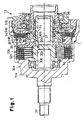
- Fig. 1 is a cross-sectional view showing a coupling device according to a first embodiment of the present invention;
- Fig. 2 is a view schematic diagram showing a four-wheel drive car loaded with the coupling device in Fig. 1;
- Fig. 3 is a cross-sectional view showing inner clutch plates and outer clutch plates included in the coupling device in Fig. 1;
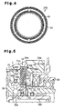
- Fig. 4 is a front view showing one of the inner clutch plates in Fig. 3;
- Fig. 5 is a partially enlarged cross-sectional view of the coupling device in Fig. 1;
- Fig. 6 is a graph showing relationship between rotational frequency of an inner shaft and drag torque in a prior art coupling device;
- Fig. 7 is a graph showing the drag torque in the prior art coupling device and drag torque in the coupling device in Fig. 1;
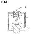
- Fig. 8 is a diagrammatic view showing a device for forming a thin carbon film in a diamond form on the outer clutch plate;
- Fig. 9 is a cross-sectional view showing a coupling device according to a second embodiment of the present invention;
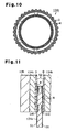
- Fig. 10 is a front view showing the outer clutch plate included in the coupling device in Fig. 9;
- Fig. 11 is a cross-sectional view showing the inner clutch plate and the outer clutch plate included in the coupling device in Fig. 9; and
- Fig. 12 is a graph showing relationship between the number of engagement repeating times and µ100/µ50 in the second embodiment.
-
- A first embodiment according to the present invention will be explained below with reference to Figs. 1 to 8.
- As shown in Fig. 2, a four-
wheel drive vehicle 12 includes acoupling device 11, a trans-axle 13, anengine 14, a pair offront wheels 15, and a pair ofrear wheels 16. Power of theengine 14 is transmitted to thefront wheels 15 via the trans-axle 13 and a pair ofaxle shafts 17. - The
coupling device 11 is provided on a power transmission route between theengine 14 and therear wheels 16. Namely, thecoupling device 11 is connected to the trans-axle 13 via apropeller shaft 18. Arear differential 20 is connected to thecoupling device 11 via adrive pinion shaft 19. Therear wheels 16 are connected to therear differential 20 via a pair ofaxle shafts 21. Thecoupling device 11 selectively permits and shuts off the transmission of torque from thepropeller shaft 18 to thedrive pinion shaft 19. - The
coupling device 11 and the rear differential 20 are housed in adifferential carrier 22 and are supported by thecarrier 22. Thedifferential carrier 22 is supported by a vehicle body of the four-wheel drive vehicle 12. - As shown in Fig. 1, the
coupling device 11 includes a first rotary member, a second rotary member, a second clutch, apilot clutch mechanism 30d, and acam mechanism 30e. In this embodiment, the first rotary member is anouter case 30a, the second rotary member is aninner shaft 30b, and the second clutch is a mainclutch mechanism 30c. - The
outer case 30a (an external rotary member) includes a closed-end cylindricalfront housing 31a and arear housing 31b screwed into thefront housing 31a so as to be placed over a rear end opening part of thefront housing 31a. Aninput shaft 50 protrudes from a front end of thefront housing 31a. Theinput shaft 50 is connected to the propeller shaft 18 (see Fig. 2). - The
front housing 31a is formed of aluminum (a non-magnetic material), and therear housing 31b is formed of iron (a magnetic material). Aring body 51 of stainless steel (a non-magnetic material) is embedded in a middle part of therear housing 31b in the radial direction. - An outer circumference part of the
front housing 31a in the vicinity of the front end is supported rotatably with respect to the differential carrier 22 (see Fig. 2) via a bearing (not shown). Therear housing 31b is supported rotatably with respect to ayoke 36, which is supported by the differential carrier 22 (see Fig. 2), via a bearing. A rear side cylindrical part of therear housing 31b is supported rotatably with respect to the differential carrier 22 (see Fig. 2) via an oil seal (not shown). - The
inner shaft 30b penetrates through a central part of therear housing 31b to be inserted into thefront housing 31a. A gap between theinner shaft 30b and therear housing 31b is sealed. Theinner shaft 30b is supported rotatably with respect to thefront housing 31a and therear housing 31b with its movement in the axial direction being restricted. A tip end portion of the drive pinion shaft 19 (see Fig. 2) is fitted into theinner shaft 30 b. Thedrive pinion shaft 19 is not shown in Fig. 1. - As shown in Fig. 1, the main
clutch mechanism 30c is a wet type clutch mechanism, and includes a plurality of iron innerclutch plates 32a and a plurality of iron outerclutch plates 32b. A wet type friction material with cellulosic fibers as a base material is stuck on both side surfaces (both sliding surfaces) of each of the innerclutch plates 32a. Consequently, when the adjacent innerclutch plate 32a and outerclutch plate 32b are engaged with each other, the materials of theplates - These
clutch plates front housing 31a. The innerclutch plates 32a are mounted to an outer circumference of theinner shaft 30b by spline fitting, and are movable in the axial direction with respect to theinner shaft 30b. - The outer
clutch plates 32b are mounted to an inner circumference of thefront housing 31a by spline fitting, and are movable in the axial direction with respect to thefront housing 31a. The innerclutch plates 32a and the outerclutch plates 32b are alternately placed. The adjacent innerclutch plate 32a and outerclutch plate 32b are capable of moving closer to each other and away from each other in the axial direction. - The
pilot clutch mechanism 30d includes anannular electromagnet 33, a first clutch, and anarmature 35. In this embodiment, the first clutch is afriction clutch 34. Theelectromagnet 33 andarmature 35 construct an electromagnetic actuator. Theelectromagnet 33 is fitted in theyoke 36. Part of theyoke 36 and theelectromagnet 33 are housed in anannular recess 53 formed in therear housing 31b. - The
friction clutch 34 includes a plurality of first clutch plates and a plurality of second clutch plates. In this embodiment, the second clutch plates are iron innerclutch plates 34a, and the first clutch plates are iron outerclutch plates 34b. The innerclutch plates 34a are mounted to an outer circumference of afirst cam member 37 constructing part of thecam mechanism 30e by spline fitting, and are movable in the axial direction with respect to thefirst cam member 37. Meanwhile, the outerclutch plates 34b are mounted to the inner circumference of thefront housing 31a by spline fitting, and are movable in the axial direction with respect to thefront housing 31a. - The inner
clutch plates 34a and the outerclutch plates 34b are alternately placed. The adjacent innerclutch plate 34a and outerclutch plate 34b are able to move close to and away from each other in the axial direction. - As shown in Fig. 3, each inner
clutch plate 34a has a pair of slidingsurfaces 51 opposing two of the outerclutch plates 34b placed at both sides of theplate 34a. Each of the two outerclutch plates 34b located at the outermost side has one sliding surface S2 corresponding to the adjacent innerclutch plate 34a. Each of the other outerclutch plates 34b has a pair of sliding surfaces S2 opposing two of the innerclutch plates 34a placed at both sides of theplate 34b. - As shown in Fig. 3 and Fig. 4, a number of
annular grooves 40 having very small width are formed with a very small pitch on each of the sliding surfaces S1 by press working. Known nitride treatment, or known quenching and tempering treatment is applied to each of the sliding surfaces S1. Though theseannular grooves 40 are illustrated to be larger than as they are for purposes of illustration, the actual pitch and height of thegroove 40 is only several µm. - As shown in Fig. 3, a thin carbon film D in a diamond form is formed on each of the sliding surfaces S2 by a known method such as the CVD (Chemical Vapor Deposition) method, the PVD (Physical Vapor Deposition) method, and the ion vapor deposition method.
- The thin carbon film D in a diamond form is formed by, for example, a forming
device 61 shown in Fig. 8. The formingdevice 61 is for performing high temperature plasma CVD, and includes a formingchamber 63 having anexhaust port 62. Acathode 64 and ananode 65 for electric discharge are placed inside the formingchamber 63. Apower supply 66 for applying DC voltage is connected to thecathode 64 and theanode 65. Asupply port 67 is formed at a tip end of theanode 65. - Raw material gas for synthesizing the thin carbon film D in a diamond form passes through a space between the
cathode 64 and theanode 65, and supplied into the formingchamber 63 from thesupply port 67. The raw material gas is decomposed and excited by the electric discharge between thecathode 64 and theanode 65, and generates plasma while passing near thesupply port 67. The inside of the formingchamber 63 is at lower pressure than atmospheric pressure during the period of time from generation of the plasma to forming of the thin carbon film D in a diamond form. Aholder 68 to set the outerclutch plate 34b is placed inside the formingchamber 63. - The plasma is applied to the sliding surface S2 of the outer
clutch plate 34b set on theholder 68, whereby the thin carbon film D in a diamond form is deposited on a surface of the sliding surface S2 until it has predetermined thickness. In this embodiment, the thickness of the thin carbon film D in a diamond form is 3 µm. - The thickness of the thin carbon film D in a diamond form is in the range of 0.1 to 10 µm, preferably in the range of 1 to 5 µm in order to protect each of the sliding surfaces S2 effectively. With the thickness less than 0.1 µm, useful life against wear is short, and is not suitable for practical use. On the other hand, if the thickness exceeds 10 µm, the thin carbon film D in a diamond form becomes brittle. The thin carbon film D in a diamond form is formed by diamond-like carbon (DLC).
- As shown in Fig. 1, the
armature 35 forming a ring shape is mounted to the inner circumference of thefront housing 31a by spline fitting, and is movable in the axial direction with respect to thefront housing 31a. Thearmature 35 is located at one side of thefriction clutch 34, and opposes thefriction clutch 34. - The
electromagnet 33 forms a magnetic path L1 circulating through theyoke 36, therear housing 31b, thefirst cam member 37, thearmature 35, thefriction clutch 34, therear housing 31b and theyoke 36 when electric current is supplied. - As shown in Fig. 1, the
cam mechanism 30e includes thefirst cam member 37, asecond cam member 38 and a plurality of ball-shapedcam follower 39. Thefirst cam member 37 and thesecond cam member 38 form substantially a disk shape. - The
first cam member 37 is rotatably fitted onto the outer circumference of theinner shaft 30b, and is supported rotatably with respect to therear housing 31b via athrust bearing 41. An inner circumference surface of thearmature 35 abuts against an outer circumference surface of thefirst cam member 37. Thefirst cam member 37 and thearmature 35 are relatively rotatable. - As shown in Fig. 5, an
annular housing groove 42a is formed in an inner circumference surface of thefirst cam member 37. A seal member, or aseal ring 42b, contacts the outer circumference surface of theinner shaft 30b and is housed inside thehousing groove 42a. Theseal ring 42b seals a gap between theinner shaft 30b and thefirst cam member 37. - An
annular housing groove 43a is formed in the inner circumference surface of thearmature 35. A seal member, orseal ring 43b, contacts the outer circumference surface of thefirst cam member 37 and is housed in thehousing groove 43a. Theseal ring 43b seals a gap between thefirst cam member 37 and thearmature 35. - An
annular housing groove 44a is formed in an outer circumference surface of thearmature 35. A seal member, or aseal ring 44b, contacts the inner circumference surface of thefront housing 31a is housed in thehousing groove 44a. Theseal ring 44b seals a gap between thearmature 35 and thefront housing 31a. - The
armature 35, thefirst cam member 37, and the seal rings 42b, 43b, and 44b, which are seal members, construct a seal mechanism I. - As shown in Fig. 1, a space enclosed by the
front housing 31a, thearmature 35, thefirst cam member 37 and theinner shaft 30b forms a first housing chamber K1. A space enclosed by theinner shaft 30b, thefirst cam member 37, thearmature 35, thefront housing 31a and therear housing 31b forms a second housing chamber K2. - The
second cam member 38 is mounted to the outer circumference of Lheinner shaft 30b by spline fitting and is movable in the axial direction with respect to theinner shaft 30b, and rotates integrally with theinner shaft 30b. Thesecond cam member 38 opposes the mainclutch mechanism 30c. - The
first cam member 37 has a plurality of cam grooves which are placed on the same circle and each placed Lo be spaced by a predetermined angle, on the surface opposing thesecond cam member 38. Thesecond cam member 38 similarly has a plurality of cam grooves which are placed on the same circle and each placed to be spaced by a predetermined angle, on the surface opposing thefirst cam member 37. Each of thecam followers 39 is placed between thecam members first cam member 37 and the corresponding cam groove on thesecond cam member 38. - Each
cam followers 39 allows relative rotation of both thecam members cam followers 39 presses thesecond cam member 38 in a direction to move away from thefirst cam member 37, namely, in a direction toward the mainclutch mechanism 30c by the action of both the corresponding cam grooves following the relative rotation of both thecam members - The
armature 35 and theelectromagnet 33 are placed to sandwich thefriction clutch 34 and therear housing 31b between them. Therear housing 31b functions as a magnet path forming member. - Lubricant oil to lubricate the
clutch plates - When an electric current is not supplied to the
electromagnet 33 of thepilot clutch mechanism 30d, an electromagnetic attraction force does not occur between theelectromagnet 33 and thearmature 35. As a result, thefriction clutch 34 is not held by therear housing 31b and thearmature 35, and the adjacent innerclutch plate 34a and outerclutch plate 34b are in the state in which they are released from the friction engagement (non-engaging state of the friction clutch 34). In this state, thefriction clutch 34 does not transmit torque to thefirst cam member 37 from thefront housing 31a, and thecam mechanism 30e does not function to press thesecond cam member 38 in the direction to the mainclutch mechanism 30c. As a result, the mainclutch mechanism 30c is in a non-engaging state in which the torque transmission to theinner shaft 30b from thefront housing 31a is shut, off, and the power of theengine 14 is not transmitted to both therear wheels 16. Accordingly, the four-wheel drive vehicle 12 is driven in a two-wheel drive mode in which only both thefront wheels 15 are driven by theengine 14. - Meanwhile, when an electric current is supplied to the
electromagnet 33, the electromagnetic attraction force occurs between theelectromagnet 33 and thearmature 35. Consequently, thefriction clutch 34 is held by therear housing 31b and thearmature 35, and both the adjacentclutch plates friction clutch 34 allows torque transmission to thefirst cam member 37 from thefront housing 31a, and thefirst cam member 37 rotates with thefront housing 31a. Thereupon, relative rotation occurs between thefirst cam member 37 and thesecond cam member 38, and thecam mechanism 30e functions to press thesecond cam member 38 in the direction toward the mainclutch mechanism 30c. - As a result, both the adjacent
clutch plates clutch mechanism 30c is in the engaging state which allows the torque transmission from thefront housing 31a to theinner shaft 30b. Accordingly, the power of theengine 14 is transmitted to both therear wheels 16 and the four-wheel drive vehicle 12 is driven in a four-wheel drive mode. - The torque transmission rate from the
front housing 31a to theinner shaft 30b is determined according to the electromagnetic attraction force occurring between theelectromagnet 33 and thearmature 35, in other words, the frictional force between both the adjacentclutch plates friction clutch 34. The electromagnetic attraction force can be adjusted by controlling the applied current to theelectromagnet 33. - By increasing the applied current to the
electromagnet 33 to a predetermined value, the electromagnetic attraction force occurring between theelectromagnet 33 and thearmature 35 increases to the extent which does not allow the friction clutch 34 to slide. As a result, thecam mechanism 30e increases the force to press thesecond cam member 38 in the direction to move to the mainclutch mechanism 30c, so that slide does not occur to the mainclutch mechanism 30c. Accordingly, theouter case 30a and theinner shaft 30b are integrally rotated, and the torque transmission rate from theouter case 30a to theinner shaft 30b becomes 100%. Consequently, the power of theengine 14 is equally transmitted to thefront wheels 15 and therear wheels 16. - Next, the characteristics of the
coupling device 11 of this embodiment will be explained comparing it with a conventional coupling device. As the conventional device, the following device is prepared. Namely, the conventional device does not include the seal rings 42b, 43b and 44b which are included in thedevice 11 of this embodiment. Therefore, in the conventional device, the gap between the first housing chamber K1 and the second housing chamber K2 is not sealed, and lubricant oil is movable between both the housing chambers K1 and K2. Further, in the conventional device, the lubricant oil of the amount corresponding to 80% of the total volumetric capacity of both the housing chambers K1 and K2 is charged in both the housing chambers K1 and K2. Accordingly, the friction clutch of the conventional device is exposed to the lubricant oil. In addition, in the conventional device, the thin carbon film D in a diamond form is not applied to each of the outer clutch plates in the friction clutch, and instead, nitride treatment or quenching and tempering treatment is applied thereto. The torque transmission ability of the conventional device is assumed to be the same as that of thedevice 11 of this embodiment. - Fig. 6 is a graph showing relationship between the rotational frequency of the inner shaft (corresponding to the
inner shaft 30b of this embodiment) and the drag torque in the conventional device. The graph in Fig. 6 is the experimental result which is obtained by rotating the inner shaft in the state in which the outer case (corresponding to theouter case 30a in this embodiment) is fixed in the environment at minus 20 degrees centigrade. - This graph shows the result of measuring the drag torque which is transmitted from the inner shaft to the outer case by the influence of the viscosity of the lubricant oil and the residual magnetism of the electromagnet in the state in which the electromagnet (corresponding to the
electromagnet 33 in this embodiment) is not energized. - The line a in the graph represents the drag torque occurring as a result that the viscosity of the lubricant oil having influence on the main clutch mechanism (corresponding to the main
clutch mechanism 30c in this embodiment). - The line b in the graph represents the sum of the drag torque shown by the line a, and the drag torque occurring as a result that the residual magnetism of the electromagnet has the influence on the friction clutch (corresponding to the friction clutch 34 in this embodiment).
- The line c in the graph represents the sum of the drag torque shown by the line b, and the drag torque occurring as a result that the viscosity of the lubricant oil has the influence on the friction clutch.
- Accordingly, in Fig. 6, when the rotational frequency of the inner shaft is 200 min-1, in other words, 200 rpm, about 14% of the drag torque is caused by the viscosity of the lubricant oil exerted on the main clutch mechanism, about 4% of the drag torque is caused by the residual magnetism of the electromagnet exerted on the friction clutch, and about 82% of the drag torque is caused by the viscosity of the lubricant oil exerted on the friction clutch. Hereinafter, the drag torque, which is caused by the viscosity of the lubricant oil exerted on the main clutch mechanism, will be referred to as torque A, the drag torque, which is caused by the residual magnetism of the electromagnet exerted on the friction clutch, will be called torque B, and the drag torque, which is caused by the viscosity of the lubricant oil exerted on the friction clutch will be called torque C.
- The torque C is larger as compared with the torque A and the torque B. The reason why the torque C is the largest is that the influence of the viscosity of the lubricant oil exerted on the friction clutch has on the main clutch mechanism after it is amplified by the cam mechanism (corresponding to the
cam mechanism 30e of this embodiment). - On the other hand, in the
device 11 of this embodiment, the lubricant oil does not exist in the second housing chamber K2 in which thefriction clutch 34 is housed, thus exerting no influence of the viscosity of the lubricant oil on thefriction clutch 34, and therefore the torque C does not occur. Accordingly, as shown in Fig. 7, when the rotational frequency of the inner shaft is 200 min-1 in the environment at -20 degrees centigrade, the drag torque is reduced by about 82% in thedevice 11 of this embodiment as compared with the conventional device. - In the friction clutch of the conventional device, the nitride treatment or the quenching and tempering treatment is applied to the outer clutch plates and the inner clutch plates. Consequently, when the outer clutch plates and the inner clutch plates are engaged by friction in the state without lubricant oil, vigorous wearing occurs. However, in the
friction clutch 34 of this embodiment, the thin carbon film D in the diamond form is applied to the sliding surfaces S2 of the outerclutch plates 34b, and therefore the sliding surfaces S2 are resistant to wear. The thin carbon film D in the diamond form also functions as a solid lubricant, and therefore the sliding surfaces S1 of the innerclutch plates 34a in sliding contact with the sliding surfaces S2 hardly wear. Accordingly, thefriction clutch 34 of this embodiment is excellent in durability. - In the conventional device, worn particles occurring in the friction clutch mix into the lubricant oil. On the other hand, in the
device 11 of this embodiment, the lubricant oil does not exist in the second housing chamber K2 housing thefriction clutch 34, and the second housing chamber K2 is sealed from the first housing chamber K1 in which the lubricant oil exists. Consequently, the worn particles occurring in the friction clutch 34 do not mix into the lubricant oil in the first housing chamber K1. - Accordingly, the
device 11 of this embodiment, in which the drag torque is decreased dramatically, is excellent in useful life, as compared with the conventional device. - Since the viscosity of the lubricant oil increases especially at a low temperature, the drag torque caused by the viscosity of the lubricant oil is increased. In the
device 11 of this embodiment, in which thefriction clutch 34 is not exposed to the lubricant oil, the influence of the drag torque caused by the temperature of the environment is eliminated as much as possible. - Prevention of leakage of the lubricant oil from the first housing chamber K1 to the second housing chamber K2 is realized by the simple construction in which the seal rings 42b, 43b and 44b are provided.
- The
annular grooves 40 provided in both the sliding surfaces S1 of each of the innerclutch plates 34a make it easy to adjust the contact area between the innerclutch plate 34a and the outerclutch plate 34b to be an optional value. - A second embodiment of the present invention will be explained below with reference to Fig. 9 to Fig. 12 with particular emphasis on a difference from the first embodiment in Fig. 1 to Fig. 8. In the second embodiment, the same components as in the first embodiment shown in Fig. 1 to Fig. 8 are given the reference numerals with 100 being added to the reference numerals given the corresponding components of the first embodiment.
- In the
device 11 shown in Fig. 1, the first housing chamber K1 in which the lubricant oil exists is sealed from the second housing chamber K2 in which the lubricant oil does not exist. The mainclutch mechanism 30c is housed in the first housing chamber K1 and thefriction clutch 34 is housed in the second housing chamber K2. - On the other hand, in this embodiment, as shown in Fiq. 9, a main
clutch mechanism 130c and afriction clutch 134 are both exposed to the lubricant oil. Namely, in adevice 111 of this embodiment, thehousing grooves device 11 in Fig. 1 are omitted, and the first housing chamber K1 and the second housing chamber K2 which are separated from each other do not exist. - An outer circumference surface of a
first cam member 137 is a little separated from an inner circumference surface of anarmature 135. The lubricant oil is charged in a single housing chamber enclosed by anouter case 130a, aninner shaft 130b, and arear housing 131b. The lubricant oil lubricates inner and outerclutch plates clutch mechanism 130c, and an innerclutch plate 134a and outerclutch plates 134b of thefriction clutch 134. - The
friction clutch 134 includes one iron innerclutch plate 134a and two iron outerclutch plates 134b which are placed at both sides of the innerclutch plate 134a. - When an electric current is supplied to the electromagnetic coil, an electromagnet 133 forms a magnetic path L2 circulating through a
yoke 136, arear housing 131b, thefriction clutch 134, anarmature 135, thefriction clutch 134, therear housing 131b and theyoke 136. - As shown in Fig. 10 and Fig. 11, a number of grooves M in a substantially net form are formed by press working on both the sliding surfaces S2 of the each outer
clutch plate 134b. The grooves M receive excessive lubricant oil existing between the innerclutch plate 134a and each of the outerclutch plates 134b opposing it. Both the sliding surfaces S1 of the innerclutch plate 134a have surface roughness (Rz) of about 13.5 µm, and the sliding surface S2 of the each outerclutch plate 134b has the surface roughness (Rz) of about 3.3 µm. Rz means ten point height irregularities (ten points average height). - The nitride treatment, or quenching and tempering treatment is applied to the each sliding surface S1.
- As shown in Fig. 11, the thin carbon film D in the diamond form is applied to the each sliding surface 32 by a known method such as the CVD (Chemical Vapor Deposition) method, the PVD (Physical Vapor Deposition) method, or the ion vapor deposition method. The thickness of the thin carbon film D in the diamond form is 3 µm, and the surface roughness (Rz) of the thin carbon film D in the diamond form is about 3.3 µm.
- Next, the characteristics of the
coupling device 111 of this embodiment will be explained with comparison with a conventional coupling device. As the conventional device, the following device is prepared. Namely, the conventional device differs from thedevice 111 of this embodiment in the point that the nitride treatment is applied to both the outer clutch plates in the friction clutch in the conventional device instead of the thin carbon film D in the diamond form is applied thereto. In the friction clutch of this conventional device, the surface roughness (Rz) of the both the sliding surfaces of the inner clutch plate is about 7.8 µm, and the surface roughness (Rz) of the sliding surface of each outer clutch plate is about 3.8 µm. The torque transmission ability of the conventional device is assumed to be the same as thedevice 111 of this embodiment. - Fig. 12 is a graph showing the relationships between the number of engagement repeating times and µ100/µ50 for the
device 111 of this embodiment and the conventional device. In the graph in Fig. 12, µ100/µ50 is plotted in the vertical axis, and the number of engagement repeating times is plotted in the horizontal axis. The number of engagement repeating times is the numerical value which is counted each time the adjacent clutch plates in the friction clutch are engaged with each other once. - µ100/µ50 shows the value obtained by dividing the friction coefficient p, which is obtained when the inner shaft is rotated at the rotational frequency v of 100 min-1 (rpm), by the friction coefficient µ, which is obtained when the same inner shaft is rotated at the rotational frequency v of 50 min-1 (rpm) in the state where the outer case is-fixed.
- The fact that the value of µ100/µ50 is 1 or more means that the larger the rotational frequency v, the larger the friction coefficient µ. This is called that the µ-v property has positive dependence on rotation speed, or positive gradient. When the µ-v property is a positive gradient, it is generally known that judder is favorably prevented.
- Judder means the phenomena in which, for example, self-excited vibrations caused by the stick slip at the sliding portions between the inner
clutch plate 134a and the outerclutch plate 134b, or the sliding portions between the innerclutch plate 132a and the outerclutch plate 132b influence the entire vehicle loaded with thecoupling device 111. - In order to reduce the stick slip, it is effective that the dependence of the friction coefficient µ with respect to the relative rotational frequency v between both the adjacent clutch plates, namely, the µ-v property is a positive gradient. When the µ-v property is a positive gradient, dµ/dv is 0 or more.
- The frictional force occurring between both the adjacent clutch plates is constituted by the sum of the a fluid friction force (shearing resistance force of the oil film) and the boundary friction force (frictional force caused by contact of both the clutch plates), and the magnitude of the friction forces per unit area is in the relationship of the fluid friction force « the boundary friction force. If the relative rotational frequency v becomes larger, the formation of the oil film is promoted, and the fluid friction force increases while the boundary friction force decreases. If the roughness of the contact surface of both the clutch plates is large, the contact of the raised portions of both the contact surfaces is maintained even if the relative rotational frequency v increases. In this case, the decrease in the boundary friction force is suppressed, the increase in the fluid friction force is suppressed, and the µ-v property tends to be a positive gradient.
- Namely, as the surface roughness of each of the
clutch plates clutch plates - As shown in the graph in Fig. 12, in the conventional device, when the number of engagement repeating time exceeds a1, the value of µ100/µ50 becomes smaller than 1, and judder occurs. The judder is caused by wear of the clutch plate in the friction clutch. Occurrence of judder means that the device is at the end of its life.
- On the other hand, in the
device 111 of this embodiment, when the number of engagement repeating times exceeds a2, the value of µ100/µ50 is smaller than 1, and judder occurs. At this time, thedevice 111 is at the end of life. - As known from the graph in the above-described Fig. 12, in the
device 111 of this embodiment including the outerclutch plates 134b to which the thin carbon film D in the diamond form is applied, the number of engagement repeating times until judder occurs increases by three times or more as compared with the conventional device. Namely, the outerclutch plates 134b of this embodiment wears less as compared with the conventional outer clutch plates. The innerclutch plate 134a of this embodiment, which slides in contact with the thin carbon film D in the diamond form, wears less as compared with Lhe conventional inner clutch plate which does not slide in contact with the thin carbon film D in the diamond form. This is because the thin carbon film D in the diamond form functions as the solid lubricant which suppress wear of the innerclutch plate 134a. - Accordingly, in this embodiment, the life of the
clutch plates coupling device 111 can be dramatically increased. - The grooves M in substantially the net form, which are provided on the sliding surface S2 of each of the outer
clutch plates 134b make it easy to adjust the contact area between the innerclutch plate 134a and the outerclutch plate 134b to be an optional value. The grooves M receive excessive lubricant oil existing between the adjacentclutch plates clutch plates friction clutch 134 are realized. - It should be apparent to those skilled in the art that the present invention may be embodied in many other specific forms without departing from the spirit or scope of the invention. Particularly, it should be understood that the invention may be embodied in the following forms.
- In the
coupling device 11 of the first embodiment, the amount of lubricant oil inside the first housing chamber K1 is 80% of the volumetric capacity of the first housing chamber Kl, but any amount may be charged if only the amount is suitable for lubrication of the mainclutch mechanism 30c. - The outer
clutch plates - In the second embodiment, the grooves M in substantially the net form are formed on each outer
clutch plate 134b, but the grooves M may be omitted. - The same grooves as the grooves M in the second embodiment may be provided on the outer
clutch plates 34b in the first embodiment. - In the first and second embodiments, the
annular grooves 40 are provided on the innerclutch plates annular grooves 40 may be omitted. - In the first embodiment, the outer
clutch plates 34b to which the thin carbon film D in Lhe diamond form is applied are adopted in thefriction clutch 34. However, without being limited to this, the thin carbon film D in the diamond form may be applied to at least one of theclutch plates clutch mechanism 30c. Such change may be embodied in thecoupling device 111 of the second embodiment. - In the first and second embodiments, the thin carbon film D in the diamond form is applied to the outer
clutch plates clutch plates - In the first and second embodiments, the thin carbon film D in the diamond form is applied to the outer
clutch plates clutch plates clutch plates clutch plates - In the first and second embodiments, the nitride treatment, or the quenching and tempering treatment is applied to the inner
clutch plates - Therefore, the present examples and embodiments are to be considered as illustrative and not restrictive and the invention is not to be limited to the details given herein, but may be modified within the scope and equivalence of the appended claims.
- A friction clutch has a plurality of iron inner clutch plates and a plurality of iron outer clutch plates. Both the clutch plates have sliding surfaces which are friction-engaged each other. A thin carbon film in a diamond form, which functions as a solid lubricant, is formed on each of the sliding surfaces of the outer clutch plates by a known method such as the Chemical Vapor Deposition method. A known nitride treatment or quenching and tempering treatment is applied to the sliding surfaces of the inner clutch plates. A coupling device has a pilot clutch mechanism with the friction clutch and an electromagnetic acLuaLor. As a result, the friction clutch is resistant to wear and the coupling device is excellent in durability.
Claims (13)
- An iron clutch plate characterized by a sliding surface that contacts another clutch plate, wherein a thin carbon film in a diamond form is formed on the sliding surface.
- The clutch plate according to claim 1, characterized in that the thin carbon film is formed by diamond-like carbon.
- A friction clutch characterized by:a first clutch plate having a first sliding surface; anda second clutch plate having a second sliding surface that contacts the first sliding surface, wherein the clutch plates friction-engage with each other to transmit torque, and wherein a thin carbon film in a diamond form is formed on at least one of the first and second sliding surfaces.
- The friction clutch according to claim 3, characterized in that the thin carbon film is formed by diamond-like carbon.
- The friction clutch according to claims 3 or 4, characterized in that the thin carbon film is formed on the first sliding surface, and wherein nitride treatment or quenching and tempering treatment is applied to the second sliding surface.
- The friction clutch according to claims 3 or 4, characterized in that the thin carbon film is formed on the first and second sliding surfaces.
- The friction clutch according to any one of claims 3 to 6, characterized in that at least one of the first and second sliding surfaces includes a plurality of grooves that extend about the rotation axis of the associated clutch plate.
- The friction clutch according to any one of claims 3 to 6, characterized in that at least one of the first and second sliding surfaces includes grooves in a substantially net form.
- The friction clutch according to claim 3, characterized in that the surface roughness of one of the first and second sliding surfaces that has the thin carbon film thereon is less than that of the other sliding surface that has no thin carbon film.
- A coupling device characterized by:a first rotary member;a second rotary member, which is rotatable relative to the first rotary member;a housing chamber defined between the first rotary member and the second rotary member, wherein the housing chamber is charged with lubricant oil; anda plurality of clutches located in the housing chamber, wherein the clutches cooperate to transmit torque between the first rotary member and the second rotary member, and wherein at least one of the clutches is a friction clutch according to any one of claims 3 to 9.
- The coupling device according to claim 10, characterized in that the plurality of clutches include a first clutch and a second clutch, at least one of which being the friction clutch, wherein the second clutch is located between the rotary members, torque being transmitted between the rotary members through the second clutch, wherein the coupling device further comprises an electromagnetic actuator for actuating the first clutch, wherein, when the electromagnetic actuator actuates the first clutch, the second clutch is actuated to transmit torque between the rotary members in accordance with motion of the first clutch.
- The coupling device according to claim 10, characterized by an electromagnetic actuator, which actuates the friction clutch such that the clutch plates friction-engage with each other, wherein the friction clutch and the electromagnetic actuator form a pilot clutch mechanism, wherein the clutches include a main clutch located between the rotary members, torque being transmitted between the rotary members through the main clutch, wherein a cam mechanism is located between the pilot clutch mechanism and the main clutch, and wherein the cam mechanism actuates the main clutch in response to motion of the pilot clutch mechanism.
- The coupling device according to claims 11 or 12, characterized in that the electromagnetic actuator includes an armature and an electromagnet for actuating the armature.
Priority Applications (1)
| Application Number | Priority Date | Filing Date | Title |
|---|---|---|---|
| EP07116861A EP1870611B1 (en) | 2001-12-25 | 2002-11-07 | Coupling device |
Applications Claiming Priority (3)
| Application Number | Priority Date | Filing Date | Title |
|---|---|---|---|
| JP2001392475 | 2001-12-25 | ||
| JP2001392475A JP4032736B2 (en) | 2001-05-09 | 2001-12-25 | Friction clutch, electromagnetic clutch mechanism, and driving force transmission device |
| EP02024825A EP1323942B1 (en) | 2001-12-25 | 2002-11-07 | Clutch plate, friction clutch, and coupling device |
Related Parent Applications (1)
| Application Number | Title | Priority Date | Filing Date |
|---|---|---|---|
| EP02024825A Division EP1323942B1 (en) | 2001-12-25 | 2002-11-07 | Clutch plate, friction clutch, and coupling device |
Related Child Applications (1)
| Application Number | Title | Priority Date | Filing Date |
|---|---|---|---|
| EP07116861A Division EP1870611B1 (en) | 2001-12-25 | 2002-11-07 | Coupling device |
Publications (2)
| Publication Number | Publication Date |
|---|---|
| EP1571365A1 true EP1571365A1 (en) | 2005-09-07 |
| EP1571365B1 EP1571365B1 (en) | 2008-01-02 |
Family
ID=19188640
Family Applications (3)
| Application Number | Title | Priority Date | Filing Date |
|---|---|---|---|
| EP05012564A Expired - Lifetime EP1571365B1 (en) | 2001-12-25 | 2002-11-07 | Clutch plate, friction clutch, and coupling device |
| EP07116861A Expired - Lifetime EP1870611B1 (en) | 2001-12-25 | 2002-11-07 | Coupling device |
| EP02024825A Expired - Lifetime EP1323942B1 (en) | 2001-12-25 | 2002-11-07 | Clutch plate, friction clutch, and coupling device |
Family Applications After (2)
| Application Number | Title | Priority Date | Filing Date |
|---|---|---|---|
| EP07116861A Expired - Lifetime EP1870611B1 (en) | 2001-12-25 | 2002-11-07 | Coupling device |
| EP02024825A Expired - Lifetime EP1323942B1 (en) | 2001-12-25 | 2002-11-07 | Clutch plate, friction clutch, and coupling device |
Country Status (3)
| Country | Link |
|---|---|
| US (2) | US6920968B2 (en) |
| EP (3) | EP1571365B1 (en) |
| DE (3) | DE60233906D1 (en) |
Cited By (2)
| Publication number | Priority date | Publication date | Assignee | Title |
|---|---|---|---|---|
| WO2006057292A1 (en) | 2004-11-26 | 2006-06-01 | Nippon Oil Corporation | Lubricant composition and driving force transmitting system using same |
| EP1783389A2 (en) * | 2005-08-30 | 2007-05-09 | Jtekt Corporation | Drive force transmission device |
Families Citing this family (23)
| Publication number | Priority date | Publication date | Assignee | Title |
|---|---|---|---|---|
| DE60233906D1 (en) * | 2001-12-25 | 2009-11-12 | Jtekt Corp | coupling device |
| JP3961879B2 (en) | 2002-05-24 | 2007-08-22 | 株式会社豊田中央研究所 | Friction clutch and driving force transmission device |
| WO2004072322A1 (en) * | 2003-02-12 | 2004-08-26 | Toyoda Koki Kabushiki Kaisha | Amorphous carbon film forming method and device |
| DE102005041080A1 (en) | 2004-08-31 | 2006-03-16 | Tochigi Fuji Sangyo K.K. | friction engagement |
| EP1683982A2 (en) * | 2005-01-20 | 2006-07-26 | LuK Lamellen und Kupplungsbau Beteiligungs KG | Method and device for detecting a damage of a clutch with at least two components transmitting a frictional torque |
| US7963852B2 (en) * | 2005-10-07 | 2011-06-21 | Jtekt Corporation | Spline shaft |
| US7510062B2 (en) * | 2005-11-14 | 2009-03-31 | Illinois Tool Works Inc. | Rotary damper |
| JP2007315583A (en) * | 2006-01-31 | 2007-12-06 | Gkn ドライブライン トルクテクノロジー株式会社 | Clutch device and differential device using it |
| DE112007000463T5 (en) * | 2006-02-28 | 2008-12-24 | Gkn Driveline Torque Technology Kk | The torque transfer device |
| JP2010112386A (en) * | 2007-02-20 | 2010-05-20 | Yamaha Motor Co Ltd | Dry clutch, transmitting member and transmitted member composing the dry clutch, and motorcycle equipped with the dry clutch |
| US7847679B2 (en) * | 2007-10-26 | 2010-12-07 | Rolls-Royce Corporation | Material wear indication system |
| US8231494B2 (en) * | 2007-11-07 | 2012-07-31 | Borg Warner, Inc. | Active control center differential with front output |
| EP2351942B1 (en) * | 2008-11-25 | 2014-04-16 | Nissan Motor Co., Ltd. | Dry clutch |
| AT510943A1 (en) * | 2011-01-13 | 2012-07-15 | Miba Frictec Gmbh | FRICTION MATERIAL |
| US8881882B2 (en) * | 2011-08-25 | 2014-11-11 | Warner Electric Technology Llc | Rotational coupling device with improved lubrication |
| US9222524B2 (en) * | 2011-11-08 | 2015-12-29 | Nissan Motor Co., Ltd. | Drive force transmission device |
| JP6044754B2 (en) * | 2012-01-19 | 2016-12-14 | 株式会社ジェイテクト | Clutch plate and manufacturing method thereof |
| RU2498486C1 (en) * | 2012-02-21 | 2013-11-10 | Федеральное государственное бюджетное образовательное учреждение высшего профессионального образования "Казанский национальный исследовательский технический университет им. А.Н. Туполева - КАИ" | Electromagnetic coupling |
| JP2014098436A (en) * | 2012-11-14 | 2014-05-29 | Jtekt Corp | Clutch plate, clutch device, and driving force transmitting device |
| EP3085812B1 (en) * | 2013-12-16 | 2018-08-08 | Aisin Seiki Kabushiki Kaisha | Sliding member |
| RU2568900C1 (en) * | 2014-06-10 | 2015-11-20 | Федеральное государственное бюджетное образовательное учреждение высшего профессионального образования "Казанский национальный исследовательский технический университет им. А.Н. Туполева-КАИ" (КНИТУ-КАИ) | Electromagnetic coupling |
| DE112016004826A5 (en) * | 2015-10-21 | 2018-07-26 | Schaeffler Technologies AG & Co. KG | Method for producing a disk set of a wet-operated friction clutch and friction clutch |
| TWI632306B (en) * | 2016-09-10 | 2018-08-11 | 本土股份有限公司 | Clutch structure |
Citations (6)
| Publication number | Priority date | Publication date | Assignee | Title |
|---|---|---|---|---|
| JPH03292385A (en) * | 1990-04-10 | 1991-12-24 | Teruyuki Tsunabuchi | Surface in sliding contact with friction material |
| US5205188A (en) * | 1990-11-05 | 1993-04-27 | Detlef Repenning | Friction pairing and process for its production |
| US5452784A (en) * | 1992-07-23 | 1995-09-26 | Nsk - Waner Kabushiki Kaisha | Frictional engagement apparatus |
| US5584776A (en) * | 1995-03-24 | 1996-12-17 | Borg-Warner Automotive, Inc. | Transfer case having parallel clutches and lockup feature |
| EP0856676A1 (en) * | 1997-01-29 | 1998-08-05 | Toyota Jidosha Kabushiki Kaisha | Clutch arrangement |
| US6006869A (en) * | 1992-03-31 | 1999-12-28 | Rancourt; Claude | Ventilated disc brake |
Family Cites Families (24)
| Publication number | Priority date | Publication date | Assignee | Title |
|---|---|---|---|---|
| US242169A (en) * | 1881-05-31 | Method of ventilating sewers and drains | ||
| US230412A (en) * | 1880-07-27 | John gardner | ||
| US3073424A (en) * | 1959-06-15 | 1963-01-15 | Eaton Mfg Co | Friction device |
| FR2029114A5 (en) | 1969-01-10 | 1970-10-16 | Rhone Poulenc Sa | |
| JPS57134068A (en) * | 1981-02-09 | 1982-08-19 | Tokyu Car Corp | Lead preventing piston ring |
| US4988421A (en) | 1989-01-12 | 1991-01-29 | Ford Motor Company | Method of toughening diamond coated tools |
| AU631037B2 (en) | 1989-12-28 | 1992-11-12 | Kabushiki Kaisha Toyota Chuo Kenkyusho | Hard and lubricant thin film of amorphous carbon-hydrogen-silicon, iron base metallic material coated therewith, and the process for producing the same |
| US5411758A (en) * | 1991-10-09 | 1995-05-02 | Norton Company | Method of making synthetic diamond wear component |
| JP3146752B2 (en) * | 1993-05-12 | 2001-03-19 | 日産自動車株式会社 | Multi-plate clutch control type differential limiter |
| US6001480A (en) * | 1993-06-11 | 1999-12-14 | Zexel Corporation | Amorphous hard carbon film and mechanical parts coated therewith |
| US5688557A (en) * | 1995-06-07 | 1997-11-18 | Lemelson; Jerome H. | Method of depositing synthetic diamond coatings with intermediates bonding layers |
| DE29610498U1 (en) * | 1996-06-14 | 1996-08-29 | Zornik Miklavz | Vehicle brake or vehicle clutch disc made of C-C / SiC material |
| CA2208718C (en) | 1996-06-27 | 2005-01-25 | Takahiro Nakahigashi | Object coated with carbon film and method of manufacturing the same |
| JP3453033B2 (en) * | 1996-10-23 | 2003-10-06 | 株式会社豊田中央研究所 | Coating member and method of manufacturing the same |
| US6158561A (en) * | 1998-04-01 | 2000-12-12 | Toyoda Koki Kabushiki Kaisha | Clutch plate |
| JP3797789B2 (en) | 1998-04-01 | 2006-07-19 | 株式会社ジェイテクト | Electromagnetic friction clutch |
| DE19823928A1 (en) | 1998-05-28 | 1999-12-09 | Kempten Elektroschmelz Gmbh | Connecting element for the non-positive connection of components |
| DE19834018C1 (en) * | 1998-07-28 | 2000-02-03 | Deutsch Zentr Luft & Raumfahrt | Method for producing a protective layer containing silicon carbide |
| WO2000079020A1 (en) | 1999-06-18 | 2000-12-28 | Nissin Electric Co., Ltd. | Carbon film and method for formation thereof and article covered with carbon film and method for preparation thereof |
| AU7641300A (en) | 1999-08-24 | 2001-03-19 | Luk Lamellen Und Kupplungsbau Beteiligungs Kg | Release system |
| JP4048701B2 (en) * | 2000-08-01 | 2008-02-20 | 株式会社ジェイテクト | Driving force transmission device |
| US6427817B1 (en) * | 2000-10-03 | 2002-08-06 | Honda Giken Kogyo Kabushiki Kaisha | Lubrication structure of electro-magnetic clutch |
| DE60233906D1 (en) | 2001-12-25 | 2009-11-12 | Jtekt Corp | coupling device |
| JP3961879B2 (en) * | 2002-05-24 | 2007-08-22 | 株式会社豊田中央研究所 | Friction clutch and driving force transmission device |
-
2002
- 2002-11-07 DE DE60233906T patent/DE60233906D1/en not_active Expired - Lifetime
- 2002-11-07 EP EP05012564A patent/EP1571365B1/en not_active Expired - Lifetime
- 2002-11-07 DE DE60224459T patent/DE60224459T2/en not_active Expired - Lifetime
- 2002-11-07 EP EP07116861A patent/EP1870611B1/en not_active Expired - Lifetime
- 2002-11-07 DE DE60205449T patent/DE60205449T2/en not_active Expired - Lifetime
- 2002-11-07 EP EP02024825A patent/EP1323942B1/en not_active Expired - Lifetime
- 2002-11-08 US US10/290,146 patent/US6920968B2/en not_active Expired - Lifetime
-
2005
- 2005-03-30 US US11/092,683 patent/US20050167225A1/en not_active Abandoned
Patent Citations (6)
| Publication number | Priority date | Publication date | Assignee | Title |
|---|---|---|---|---|
| JPH03292385A (en) * | 1990-04-10 | 1991-12-24 | Teruyuki Tsunabuchi | Surface in sliding contact with friction material |
| US5205188A (en) * | 1990-11-05 | 1993-04-27 | Detlef Repenning | Friction pairing and process for its production |
| US6006869A (en) * | 1992-03-31 | 1999-12-28 | Rancourt; Claude | Ventilated disc brake |
| US5452784A (en) * | 1992-07-23 | 1995-09-26 | Nsk - Waner Kabushiki Kaisha | Frictional engagement apparatus |
| US5584776A (en) * | 1995-03-24 | 1996-12-17 | Borg-Warner Automotive, Inc. | Transfer case having parallel clutches and lockup feature |
| EP0856676A1 (en) * | 1997-01-29 | 1998-08-05 | Toyota Jidosha Kabushiki Kaisha | Clutch arrangement |
Non-Patent Citations (1)
| Title |
|---|
| PATENT ABSTRACTS OF JAPAN vol. 016, no. 126 (C - 0923) 31 March 1992 (1992-03-31) * |
Cited By (4)
| Publication number | Priority date | Publication date | Assignee | Title |
|---|---|---|---|---|
| WO2006057292A1 (en) | 2004-11-26 | 2006-06-01 | Nippon Oil Corporation | Lubricant composition and driving force transmitting system using same |
| EP1783389A2 (en) * | 2005-08-30 | 2007-05-09 | Jtekt Corporation | Drive force transmission device |
| EP1783389A3 (en) * | 2005-08-30 | 2007-05-16 | Jtekt Corporation | Drive force transmission device |
| US7677375B2 (en) | 2005-08-30 | 2010-03-16 | Jtekt Corporation | Drive force transmission device |
Also Published As
| Publication number | Publication date |
|---|---|
| EP1323942B1 (en) | 2005-08-10 |
| EP1571365B1 (en) | 2008-01-02 |
| EP1323942A1 (en) | 2003-07-02 |
| DE60205449D1 (en) | 2005-09-15 |
| DE60224459D1 (en) | 2008-02-14 |
| DE60233906D1 (en) | 2009-11-12 |
| US20030106759A1 (en) | 2003-06-12 |
| EP1870611A1 (en) | 2007-12-26 |
| US6920968B2 (en) | 2005-07-26 |
| DE60224459T2 (en) | 2008-12-18 |
| DE60205449T2 (en) | 2006-03-30 |
| EP1870611B1 (en) | 2009-09-30 |
| US20050167225A1 (en) | 2005-08-04 |
Similar Documents
| Publication | Publication Date | Title |
|---|---|---|
| EP1571365B1 (en) | Clutch plate, friction clutch, and coupling device | |
| EP1367279B1 (en) | Friction clutch plate lining and coupling device using the same | |
| EP0947720B1 (en) | Clutch plate | |
| US7677375B2 (en) | Drive force transmission device | |
| US9133891B2 (en) | Friction clutch plate, friction clutch and driving force transmission apparatus | |
| US4033438A (en) | Roller spline | |
| JP4032736B2 (en) | Friction clutch, electromagnetic clutch mechanism, and driving force transmission device | |
| JP2003035325A (en) | Wet type multiple disc clutch | |
| JP2006250364A (en) | Drive power transmitting device | |
| EP1338816A2 (en) | Rotation transmitting apparatus | |
| JP2002213485A (en) | Drive force transmission device | |
| EP1227259A2 (en) | Drive force transmission apparatus | |
| JP2005325908A (en) | Rotation transmitting device | |
| JP4140858B2 (en) | Driving force transmission device | |
| JP2005036863A (en) | Friction clutch and driving force transmission device | |
| JP7046658B2 (en) | Rotation transmission device | |
| JP2004116763A (en) | Clutch plate, friction clutch, driving force transmission device, and manufacturing method of clutch plate | |
| JP2006189076A (en) | Rotation transmission device | |
| JP3216391B2 (en) | Magnetic particle type torque limiter and method of manufacturing the same | |
| EP0809042A2 (en) | Frictional engagement element with stationary servo cylinder for planetary transmission | |
| JPH0643365U (en) | Electromagnetic clutch | |
| JP2005344877A (en) | Thrust roller bearing | |
| JP2009243578A (en) | Driving force distribution device |
Legal Events
| Date | Code | Title | Description |
|---|---|---|---|
| PUAI | Public reference made under article 153(3) epc to a published international application that has entered the european phase |
Free format text: ORIGINAL CODE: 0009012 |
|
| AC | Divisional application: reference to earlier application |
Ref document number: 1323942 Country of ref document: EP Kind code of ref document: P |
|
| AK | Designated contracting states |
Kind code of ref document: A1 Designated state(s): DE FR GB |
|
| 17P | Request for examination filed |
Effective date: 20060306 |
|
| AKX | Designation fees paid |
Designated state(s): DE FR GB |
|
| RAP1 | Party data changed (applicant data changed or rights of an application transferred) |
Owner name: JTEKT CORPORATION |
|
| RIN1 | Information on inventor provided before grant (corrected) |
Inventor name: SAITO, TOSHIYUKI Inventor name: SAKAI, NAOYUKI Inventor name: ANDO, JUNJI Inventor name: TASHIRO, AKIYOSHI Inventor name: SAKAI, TOSHIFUMI |
|
| GRAP | Despatch of communication of intention to grant a patent |
Free format text: ORIGINAL CODE: EPIDOSNIGR1 |
|
| GRAS | Grant fee paid |
Free format text: ORIGINAL CODE: EPIDOSNIGR3 |
|
| GRAA | (expected) grant |
Free format text: ORIGINAL CODE: 0009210 |
|
| AC | Divisional application: reference to earlier application |
Ref document number: 1323942 Country of ref document: EP Kind code of ref document: P |
|
| AK | Designated contracting states |
Kind code of ref document: B1 Designated state(s): DE FR GB |
|
| REG | Reference to a national code |
Ref country code: GB Ref legal event code: FG4D |
|
| RIN1 | Information on inventor provided before grant (corrected) |
Inventor name: SAKAI, TOSHIFUMIC/O JTEKT CORPORATION Inventor name: SAITO, TOSHIYUKIC/O JTEKT CORPORATION Inventor name: ANDO, JUNJIC/O JTEKT CORPORATION Inventor name: SAKAI, NAOYUKIC/O JTEKT CORPORATION Inventor name: TASHIRO, AKIYOSHIC/O JTEKT CORPORATION |
|
| REF | Corresponds to: |
Ref document number: 60224459 Country of ref document: DE Date of ref document: 20080214 Kind code of ref document: P |
|
| ET | Fr: translation filed | ||
| PLBE | No opposition filed within time limit |
Free format text: ORIGINAL CODE: 0009261 |
|
| STAA | Information on the status of an ep patent application or granted ep patent |
Free format text: STATUS: NO OPPOSITION FILED WITHIN TIME LIMIT |
|
| 26N | No opposition filed |
Effective date: 20081003 |
|
| REG | Reference to a national code |
Ref country code: FR Ref legal event code: PLFP Year of fee payment: 14 |
|
| REG | Reference to a national code |
Ref country code: FR Ref legal event code: PLFP Year of fee payment: 15 |
|
| REG | Reference to a national code |
Ref country code: FR Ref legal event code: PLFP Year of fee payment: 16 |
|
| REG | Reference to a national code |
Ref country code: FR Ref legal event code: PLFP Year of fee payment: 17 |
|
| PGFP | Annual fee paid to national office [announced via postgrant information from national office to epo] |
Ref country code: DE Payment date: 20201028 Year of fee payment: 19 Ref country code: FR Payment date: 20201013 Year of fee payment: 19 Ref country code: GB Payment date: 20201028 Year of fee payment: 19 |
|
| REG | Reference to a national code |
Ref country code: DE Ref legal event code: R119 Ref document number: 60224459 Country of ref document: DE |
|
| GBPC | Gb: european patent ceased through non-payment of renewal fee |
Effective date: 20211107 |
|
| PG25 | Lapsed in a contracting state [announced via postgrant information from national office to epo] |
Ref country code: GB Free format text: LAPSE BECAUSE OF NON-PAYMENT OF DUE FEES Effective date: 20211107 Ref country code: DE Free format text: LAPSE BECAUSE OF NON-PAYMENT OF DUE FEES Effective date: 20220601 |
|
| PG25 | Lapsed in a contracting state [announced via postgrant information from national office to epo] |
Ref country code: FR Free format text: LAPSE BECAUSE OF NON-PAYMENT OF DUE FEES Effective date: 20211130 |