EP1699194A1 - Multi-branch equalizer processing module for interference cancellation within a wireless terminal - Google Patents
Multi-branch equalizer processing module for interference cancellation within a wireless terminal Download PDFInfo
- Publication number
- EP1699194A1 EP1699194A1 EP20060003638 EP06003638A EP1699194A1 EP 1699194 A1 EP1699194 A1 EP 1699194A1 EP 20060003638 EP20060003638 EP 20060003638 EP 06003638 A EP06003638 A EP 06003638A EP 1699194 A1 EP1699194 A1 EP 1699194A1
- Authority
- EP
- European Patent Office
- Prior art keywords
- burst
- equalizer
- branch
- frame
- data bits
- Prior art date
- Legal status (The legal status is an assumption and is not a legal conclusion. Google has not performed a legal analysis and makes no representation as to the accuracy of the status listed.)
- Granted
Links
Images


Classifications
-
- H—ELECTRICITY
- H04—ELECTRIC COMMUNICATION TECHNIQUE
- H04L—TRANSMISSION OF DIGITAL INFORMATION, e.g. TELEGRAPHIC COMMUNICATION
- H04L25/00—Baseband systems
- H04L25/02—Details ; arrangements for supplying electrical power along data transmission lines
- H04L25/03—Shaping networks in transmitter or receiver, e.g. adaptive shaping networks
- H04L25/03006—Arrangements for removing intersymbol interference
- H04L25/03171—Arrangements involving maximum a posteriori probability [MAP] detection
-
- H—ELECTRICITY
- H04—ELECTRIC COMMUNICATION TECHNIQUE
- H04L—TRANSMISSION OF DIGITAL INFORMATION, e.g. TELEGRAPHIC COMMUNICATION
- H04L25/00—Baseband systems
- H04L25/02—Details ; arrangements for supplying electrical power along data transmission lines
- H04L25/03—Shaping networks in transmitter or receiver, e.g. adaptive shaping networks
- H04L25/03006—Arrangements for removing intersymbol interference
- H04L25/03012—Arrangements for removing intersymbol interference operating in the time domain
- H04L25/03114—Arrangements for removing intersymbol interference operating in the time domain non-adaptive, i.e. not adjustable, manually adjustable, or adjustable only during the reception of special signals
- H04L25/03133—Arrangements for removing intersymbol interference operating in the time domain non-adaptive, i.e. not adjustable, manually adjustable, or adjustable only during the reception of special signals with a non-recursive structure
Definitions
- the present invention relates generally to cellular wireless communication systems, and more particularly to the cancellation of interference associated with received data communications processed by a wireless terminal within a wireless communication system.
- Cellular wireless communication systems support wireless communication services in many populated areas of the world. While cellular wireless communication systems were initially constructed to service voice communications, they are now called upon to support data communications as well. The demand for data communication services has exploded with the acceptance and widespread use of the Internet. While data communications have historically been serviced via wired connections, cellular wireless users now demand that their wireless units also support data communications. Many wireless subscribers now expect to be able to "surf" the Internet, access their email, and perform other data communication activities using their cellular phones, wireless personal data assistants, wirelessly linked notebook computers, and/or other wireless devices. The demand for wireless communication system data communications continues to increase with time. Thus, existing wireless communication systems are currently being created/modified to service these burgeoning data communication demands.
- Cellular wireless networks include a "network infrastructure" that wirelessly communicates with wireless terminals within a respective service coverage area.
- the network infrastructure typically includes a plurality of base stations dispersed throughout the service coverage area, each of which supports wireless communications within a respective cell (or set of sectors).
- the base stations couple to base station controllers (BSCs), with each BSC serving a plurality of base stations.
- BSC base station controllers
- Each BSC couples to a mobile switching center (MSC).
- MSC mobile switching center
- Each BSC also typically directly or indirectly couples to the Internet.
- each base station communicates with a plurality of wireless terminals operating in its cell/sectors.
- a BSC coupled to the base station routes voice communications between the MSC and the serving base station.
- the MSC routes the voice communication to another MSC or to the PSTN.
- BSCs route data communications between a servicing base station and a packet data network that may include or couple to the Internet. Transmissions from base stations to wireless terminals are referred to as "forward link” transmissions while transmissions from wireless terminals to base stations are referred to as "reverse link" transmissions.
- Wireless links between base stations and their serviced wireless terminals typically operate according to one (or more) of a plurality of operating standards. These operating standards define the manner in which the wireless link may be allocated, setup, serviced, and torn down.
- GSM Global System for Mobile telecommunications
- the GSM standard, or simply GSM, is predominant in Europe and is in use around the globe. While GSM originally serviced only voice communications, it has been modified to also service data communications.
- GSM General Packet Radio Service (GPRS) operations and the Enhanced Data rates for GSM (or Global) Evolution (EDGE) operations coexist with GSM by sharing the channel bandwidth, slot structure, and slot timing of the GSM standard.
- the GPRS operations and the EDGE operations may also serve as migration paths for other standards as well, e.g., IS-136 and Pacific Digital Cellular (PDC).
- PDC Pacific Digital Cellular
- EDGE In order for EDGE to provide increased data rates within a 200 KHz GSM channel, it employs a higher order modulation, 8-PSK (octal phase shift keying), in addition to GSM's standard Gaussian Minimum Shift Keying (GMSK) modulation.
- GMSK Gaussian Minimum Shift Keying
- EDGE allows for nine different (autonomously and rapidly selectable) air interface formats, known as Modulation and Coding schemes (MCSs), with varying degrees of error control protection.
- MCSs Modulation and Coding schemes
- Low MCS modes, (MCS 1-4) use GMSK (low data rate) while high MCS modes (MCS 5-9) use 8-PSK (high data rate) modulation for over the air transmissions, depending upon the instantaneous demands of the application.
- a multi-branch equalizer processing module operable to cancel interference associated with received radio frequency (RF) burst(s) is provided, comprising:
- FIG. 1 is a system diagram illustrating a portion of a cellular wireless communication system that supports wireless terminals operating according to the present invention
- FIG. 2 is a block diagram functionally illustrating a wireless terminal constructed according to the present invention
- FIG. 3 is a block diagram illustrating the general structure of a GSM frame and the manner in which data blocks are carried by the GSM frame;
- FIG. 4 is a block diagram illustrating the formation of down link transmissions
- FIG. 5 is a block diagram illustrating the stages associated with recovering a data block from a series of RF bursts
- FIG. 6 is a block diagram illustrating the stages associated with recovering a voice data from a series of RF bursts
- FIG. 7 is a block diagram illustrating the stages associated with recovering a burst from a data or voice frame
- FIGs. 8A and 8B are flow charts illustrating operation of a wireless terminal in receiving and processing a RF burst
- FIG. 9 is a block diagram illustrating components of a multi-branch burst equalization component according to an embodiment of the present invention.
- FIG. 10 is a block diagram illustrating components of a burst equalization component according to an embodiment of the present invention.
- FIG. 11 is a block diagram illustrating components of a burst equalization component according to an embodiment of the present invention.
- FIG. 12 is a flow chart illustrating operation according to an embodiment of the present invention.
- FIGs. Preferred embodiments of the present invention are illustrated in the FIGs., like numerals being used to refer to like and corresponding parts of the various drawings.
- the present invention provides a multi-branch equalizer processing module operable to cancel interference associated with received radio frequency (RF) burst(s).
- This multi-branch equalizer processing module includes multiple equalizer processing branches.
- One equalizer processing branch is operable to be trained based upon known training sequences and equalize the received RF burst. These results are then further processed and used to train a second equalizer processing branch.
- the second equalizer processing branch then equalizes the received RF burst to produce an output based on canceling the interfering signals that results in improved processing of the received RF bursts.
- FIG. 1 is a system diagram illustrating a portion of a cellular wireless communication system 100 that supports wireless terminals operating in accordance with embodiments of the present invention.
- Cellular wireless communication system 100 includes a Mobile Switching Center (MSC) 101, Serving GPRS Support Node/Serving EDGE Support Node (SGSN/SESN) 102, base station controllers (BSCs) 152 and 154, and base stations 103, 104, 105, and 106.
- the SGSN/SESN 102 couples to the Internet 114 via a GPRS Gateway Support Node (GGSN) 112.
- a conventional voice terminal 121 couples to the PSTN 110.
- a Voice over Internet Protocol (VoIP) terminal 123 and a personal computer 125 couple to the Internet 114.
- the MSC 101 couples to the Public Switched Telephone Network (PSTN) 110.
- PSTN Public Switched Telephone Network
- Each of the base stations 103-106 services a cell/set of sectors within which it supports wireless communications.
- Wireless links that include both forward link components and reverse link components support wireless communications between the base stations and their serviced wireless terminals. These wireless links can result in co-channel and adjacent channel signals that may appear as noise which may be colored or white. As previously stated, this noise may interfere with the desired signal of interest.
- the present invention provides techniques for canceling such interference in poor signal-to-noise ratio (SNR) or low signal-to-interference ratio (SIR) environments.
- SNR signal-to-noise ratio
- SIR signal-to-interference ratio
- the cellular wireless communication system 100 may also be backward compatible in supporting analog operations as well.
- the cellular wireless communication system 100 may support the Global System for Mobile telecommunications (GSM) standard and also the Enhanced Data rates for GSM (or Global) Evolution (EDGE) extension thereof.
- the cellular wireless communication system 100 may also support the GSM General Packet Radio Service (GPRS) extension to GSM.
- GSM Global System for Mobile telecommunications
- EDGE Enhanced Data rates for GSM
- GPRS General Packet Radio Service
- the present invention is also applicable to other standards as well, e.g., TDMA standards, CDMA standards, etc.
- teachings of the present invention apply to digital communication techniques that address the identification and cancellation of interfering communications.
- Wireless terminals 116, 118, 120, 122, 124, 126, 128, and 130 couple to the cellular wireless communication system 100 via wireless links with the base stations 103-106.
- wireless terminals may include cellular telephones 116 and 118, laptop computers 120 and 122, desktop computers 124 and 126, and data terminals 128 and 130.
- the cellular wireless communication system 100 supports communications with other types of wireless terminals as well.
- devices such as laptop computers 120 and 122, desktop computers 124 and 126, data terminals 128 and 130, and cellular telephones 116 and 118, are enabled to "surf" the Internet 114, transmit and receive data communications such as email, transmit and receive files, and to perform other data operations.
- wireless terminals 116-130 are therefore enabled to support the EDGE operating standard. These wireless terminals 116-130 also support the GSM standard and may support the GPRS standard.
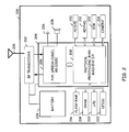
- FIG. 2 is a block diagram functionally illustrating wireless terminal 200.
- the wireless terminal 200 of FIG. 2 includes an RF transceiver 202, digital processing components 204, and various other components contained within a housing.
- the digital processing components 204 includes two main functional components, a physical layer processing, speech COder/DECoder (CODEC), and baseband CODEC functional block 206 and a protocol processing, man-machine interface functional block 208.
- a Digital Signal Processor (DSP) is the major component of the physical layer processing, speech COder/DECoder (CODEC), and baseband CODEC functional block 206 while a microprocessor, e.g., Reduced Instruction Set Computing (RISC) processor, is the major component of the protocol processing, man-machine interface functional block 208.
- the DSP may also be referred to as a Radio Interface Processor (RIP) while the RISC processor may be referred to as a system processor.
- RIP Radio Interface Processor
- RISC processor may be referred to
- RF transceiver 202 couples to an antenna 203, to the digital processing components 204, and also to battery 224 that powers all components of wireless terminal 200.
- the physical layer processing, speech COder/DECoder (CODEC), and baseband CODEC functional block 206 couples to the protocol processing, man-machine interface functional block 208 and to a coupled microphone 226 and speaker 228.
- the protocol processing, man-machine interface functional block 208 couples to various components such as, but not limited to, Personal Computing/Data Terminal Equipment interface 210, keypad 212, Subscriber Identification Module (SIM) port 213, a camera 214, flash RAM 216, SRAM 218, LCD 220, and LED(s) 222. When camera 214 and LCD 220 are present, these components may support either/both still pictures and moving pictures.
- the wireless terminal 200 of FIG. 2 may be operable to support video services as well as audio services via the cellular network.
- FIG. 3 is a block diagram illustrating the general structure of a GSM frame and the manner in which data blocks are carried by the GSM frame.
- the GSM frame 20 ms in duration, is divided into quarter frames, each of which includes eight time slots, time slots 0 through 7.
- Each time slot is approximately 625 us in duration, includes a left side, a right side, and a midamble.
- the left side and right side of an RF burst of the time slot carry data while the midamble is a training sequence.
- RF bursts of four time slots of the GSM frame carry a segmented RLC block, a complete RLC block, or two RLC blocks, depending upon a supported Modulation and Coding Scheme (MCS) mode.
- MCS Modulation and Coding Scheme
- data block A is carried in slot 0 of quarter frame 1, slot 0 of quarter frame 2, slot 0 of quarter frame 3, and slot 0 of quarter frame 3.
- Data block A may carry a segmented RLC block, an RLC block, or two RLC blocks.
- data block B is carried in slot 1 of quarter frame 1, slot 1 of quarter frame 2, slot 1 of quarter frame 3, and slot 1 of quarter frame 3.
- the MCS mode of each set of slots, i.e., slot n of each quarter frame, for the GSM frame is consistent for the GSM frame but may vary from GSM frame to GSM frame. Further, the MCS mode of differing sets of slots of the GSM frame, e.g., slot 0 of each quarter frame vs. any of slots 1-7 of each quarter frame, may differ.
- the RLC block may carry voice data or other data.
- FIG. 4 generally depicts the various stages associated with mapping data into RF bursts.
- Data is initially uncoded and maybe accompanied by a data block header.
- Block coding operations perform the outer coding for the data block and support error detection/correction for data block.
- the outer coding operations typically employ a cyclic redundancy check (CRC) or a Fire Code.
- CRC cyclic redundancy check
- the outer coding operations are illustrated to add tail bits and/or a Block Code Sequence (BCS), which is/are appended to the data.
- CS-1 the header and data are coded together using block coding and convolutional coding.
- non-CS-1 coding schemes the header and data information are often coded separately.
- Fire codes allow for either error correction or error detection.
- Fire Codes are a shortened binary cyclic code that appends redundancy bits to bits of the data Header and Data.
- the pure error detection capability of Fire Coding may be sufficient to let undetected errors go through with only a probability of 2 -40 .
- After block coding has supplemented the Data with redundancy bits for error detection, calculation of additional redundancy for error correction to correct the transmissions caused by the radio channels.
- the internal error correction or coding scheme is based on convolutional codes.
- Some redundant bits generated by the convolutional encoder may be punctured prior to transmission. Puncturing increases the rate of the convolutional code and reduces the redundancy per data block transmitted. Puncturing additionally lowers the bandwidth requirements such that the convolutional encoded signal fits into the available channel bit stream.
- the convolutional encoded punctured bits are passed to an interleaver, which shuffles various bit streams and segments the interleaved bit streams into the 4 bursts shown.
- FIG. 5 is a block diagram that generally depicts the various stages associated with recovering a data block from a RF burst(s).
- Four RF bursts typically make up a data block. These bursts are received and processed. Once all four RF bursts have been received, the RF bursts are combined to form an encoded data block.
- the encoded data block is then depunctured (if required), decoded according to an inner decoding scheme, and then decoded according to an outer decoding scheme.
- the decoded data block includes the data block header and the data. Depending on how the data and header are coded, partial decoding may be possible to identify data
- FIG. 6 is a block diagram that depicts the various stages associated with recovering data from a transmitted voice frame. This is similar to the process described with reference to FIG. 5.
- a 20 millisecond voice frame is transmitted, wherein the first half of the 20 millisecond voice frame is transmitted within a first series of RF bursts and the second half of the voice frame is transmitted with a second series of RF bursts.
- a series of four RF bursts is shown as being off-set by 10 milliseconds from the first voice frame, Voice Frame n , wherein the second half of Voice Frame n and the first half of the subsequent voice frame, Voice Frame n+1 , are coded and interleaved into the series of four RF bursts.
- the coded block produced produces a data stream that comprises the second half of Voice Frame n and the first half of Voice Frame n+1 .
- the first half of Voice Frame n stored within memory, may be combined with the second half of Voice Frame n to produce the data associated with a valid Voice Frame n .
- Re-encoding the data associated with a valid Voice Frame n may result in an at least partially re-encoded data bursts that may be used to train the second equalizer processing branch.
- the first half of the voice frame recovered from a previous set of RF bursts and the second half of the voice frame recovered from the current set of RF bursts are combined to produce the data associated with a voice frame.
- This voice frame may be validated and corrected using cycle redundancy checks in order to produce a valid voice frame.
- This valid voice frame may then be re-encoded.
- only the second half of the re-encoded Voice Frame n is used to partially recreate the burst(s).
- the second half of re-encoded Voice Frame n may be segmented and interleaved to produce a series of partially encoded RF bursts. Since the processing of the second half of the Voice Frame n+1 has not occurred, the RF bursts are only partially re-encoded. Since Voice Frame n+1 has not been validated, the first half of a re-encoded Voice Frame n+1 is not possible and is not used to recreate the burst(s).
- the partially re-encoded burst(s), based on Voice Frame n taken together with the known training sequences are operable to better train the second equalizer-processing branch in accordance with an embodiment of the present invention.
- FIGs. 8A and 8B are flow charts illustrating operation of a wireless terminal 200 in receiving and processing a RF burst.
- the operations illustrated in FIGs. 8A and 8B correspond to a single RF burst in a corresponding slot of GSM frame.
- the RF front end, the baseband processor, and the equalizer processing module perform these operations. These operations are generally called out as being performed by one of these components. However, the split of processing duties among these various components may differ without departing from the scope of the present invention.
- operation commences with the RF front end receiving an RF burst in a corresponding slot of a GSM frame (step 802).
- the RF front end then converts the RF burst to a baseband signal (step 804).
- the RF front end sends an interrupt to the baseband processor (step 806).
- the RF front end performs steps 802-806.
- the baseband processor receiving the baseband signal (step 808).
- the RF front end, the baseband processor, or modulator/demodulator will sample the analog baseband signal to digitize the baseband signal.
- the baseband processor After receipt of the baseband signal (in a digitized format), the baseband processor performs blind detection of a modulation format of the baseband signal of step 810. This blind detection of the modulation format determines the modulation format of the corresponding baseband signal.
- the modulation format will be either Gaussian Minimum Shift Keying (GMSK) modulation or Eight Phase Shift Keying (8PSK) modulation.
- GMSK Gaussian Minimum Shift Keying
- 8PSK Eight Phase Shift Keying
- the baseband processor performs de-rotation and frequency correction of the baseband signal at step 814.
- the baseband processor performs burst power estimation of the baseband signal at step 816.
- the baseband processor next performs timing, channel, noise, and signal-to-noise ratio (SNR) estimation at step 820.
- the baseband processor performs automatic gain control (AGC) loop calculations (step 822).
- AGC automatic gain control
- the baseband processor performs soft decision scaling factor determination on the baseband signal (step 824). After step 824, the baseband processor performs matched filtering operations on the baseband signal at step 826.
- Steps 808-826 are referred to hereinafter as pre-equalization processing operations.
- the baseband processor performing these pre-equalization processing operations on the baseband signal it produces a processed baseband signal.
- the baseband prucessor issues a command to the equalizer module.
- the equalizer module upon receiving the command, prepares to equalize the processed baseband signal based upon the modulation format, e.g., GMSK modulation or 8PSK modulation.
- the equalizer module receives the processed baseband signal, settings, and/or parameters from the baseband processor and performs Maximum Likelihood Sequence Estimation (MLSE) equalization on the left side of the baseband signal at step 828.
- MBE Maximum Likelihood Sequence Estimation
- the equalizer module equalizes the left side of the RF burst to produce soft decisions for the left side. Then, the equalizer module equalizes the right side of the processed baseband signal at step 830. The equalization of the right side produces a plurality of soft decisions corresponding to the right side.
- the burst equalization is typically based of known training sequences within the bursts. However, the embodiments of the present invention may utilize re-encoded or partially re-encoded data to improve the equalization process. This may take the form of an iterative process wherein a first branch performs burst equalization and a second module performs a second equalization based on the result obtained with the first branch over a series of RF bursts.
- the equalizer module then issues an interrupt to the baseband processor indicating that the equalizer operations are complete for the RF burst.
- the baseband processor then receives the soft decisions from the equalizer module.
- the baseband processor determines an average phase of the left and right sides based upon the soft decisions received from the equalizer module at step 832.
- the baseband processor then performs frequency estimation and tracking based upon the soft decisions received from the equalizer module at step 836.
- the operations of step 832, or step 854 and step 836 are referred to herein as "post-equalization processing.” After operation at step 836, processing of the particular RF burst is completed.
- the baseband processor and equalizer module take the right branch from step 812 when an 8PSK modulation is blindly detected at step 810.
- the baseband processor performs de-rotation and frequency correction on the baseband signal at step 818.
- the baseband processor then performs burst power estimation of the baseband singal at step 820.
- FIG. 8B via off page connector B, operation continues with the baseband processor performing timing, channel, noise, and SNR estimations at step 840.
- the baseband processor then performs AGC loop calculations on the baseband signal at step 842.
- the baseband processor calculates Decision Feedback Equalizer (DFE) coefficients that will be used by the equalizer module at step 844.
- DFE Decision Feedback Equalizer
- the baseband processor then performs pre-equalizer operations on the baseband signal at step 846. Finally, the baseband processor determines soft decision scaling factors for the baseband signal at step 848. Steps 818-848 performed by the baseband processor 30 are referred to herein as ''pre-equalization processing" operations for an 8PSK modulation baseband signal. Upon completion of step 648, the baseband processor issues a command to equalizer module to equalize the processed baseband signal.
- the equalizer module Upon receipt of the command from the baseband processor, the equalizer module receives the processed baseband signal, settings, and/or parameters from the baseband processor and commences equalization of the processed baseband signal. The equalizer module first prepares state values that it will use in equalizing the 8PSK modulated processed baseband signal at step 850. In the illustrated embodiment, the equalizer module uses a Maximum A posteriori Probability (MAP) equalizer. The equalizer module then equalizes the left and right sides of the processed baseband signal using the MAP equalizer to produce soft decisions for the processed baseband signal at step 852. Upon completion of step 854, the equalizer module issues an interrupt to the baseband processor indicating its completion of the equalizing the processed baseband signal corresponding.
- MAP Maximum A posteriori Probability
- the baseband processor then receives the soft decisions from the equalizer module. Next, the baseband processor determines the average phase of the left and right sides of the processed baseband signal based upon the soft decisions (step 854). Finally, the baseband processor performs frequency estimation and tracking for the soft decisions (step 836).
- the operations of steps 854 and 836 are referred to as post-equalization processing operations. From step 836, operation is complete for the particular RF burst depicts the various stages associated with recovering a data block from an RF Burst.
- FIGs. 8A and 8B are indicated to be performed by particular components of the wireless terminal, such segmentation of operations could be performed by differing components.
- the equalization operations could be performed by the baseband processor or system processor in other embodiments.
- decoding operations could also be performed by the baseband processor or the system processor in other embodiments.
- FIG. 9 is a block diagram illustrating the structure of one embodiment of a multi-branch equalizer processing module 900 operable to perform single antenna interference cancellation (SAIC) in accordance with embodiments of the present invention.
- SAIC single antenna interference cancellation
- JD joint-detection
- BIC blind interference cancellation
- the components illustrated in FIG. 9 may be hardware components, software components executed by a processor, e.g., 206 or 208 of FIG. 2, or a combination of hardware components and software components.
- Multi-branch equalizer processing module 900 includes a first equalizer processing branch 902 and second equalizer processing branch 904.
- Derotation block 906 receives In phase (I) and Quadrature (Q) components of a baseband burst. This baseband burst corresponds to RF burst(s), which were described with reference to FIGs. 3-7. Derotation block 906 derotates received I and Q burst samples and produces I and Q burst samples ("bursts").
- first equalizer processing branch 902 may include a burst equalizer. These samples may be later equalized in accordance with the embodiments of the present invention with other samples making up a data packet, e.g., RLC packet. The iterative processes of the second equalizer processing branch may be performed in addition to the burst level equalization during certain operating conditions.
- Burst equalizers include I and Q Finite Impulse Response (FIR) filters 908 and 910 and Minimum Least Squares Estimation (MLSE) equalizer 912 that operate upon each burst received from derotation block 906. These components are trained by training module 913 using known Training Sequence(s) (TS), within the midamble received with each burst. Alternately, these components could be trained over multiple bursts.
- First equalizer processing branch 902 produces soft decisions wherein multiple soft decisions represent each data bit prior to decoding. Each soft sample is provided to deinterleaver 914 which in turn provides the deinterleaved soft samples to channel decoder 916.
- Channel decoder 916 decodes a data frame from the soft samples (i.e. the multiple soft sample(s) that represent each data bit are decoded by the channel decoder to produce hard bits after decoding).
- the data frame produced by channel decoder 916 may be validated and re-encoded using re-encoder 918 in order to produce re-encoded data bits.
- Interleaver 920 receives the re-encoded data bits to produce a re-encoded data burst(s).
- the re-encoded data burst(s), along with known training sequence(s), may then be used to train second equalizer processing branch 310.
- Second equalizer processing branch 906 includes a buffer 922 operable to store multiple bursts in memory as well as an I and Q FIR filters 924 and 926, respectively.
- I and Q filters 924 and 926 are operable to be trained by training module 928 using known training sequence and at least partially re-encoded bursts.
- the second equalizer processing branch takes at least partially re-encoded data and known training sequences to train the I and Q RF filters. This results in an improved SNR for the burst(s) processed from buffer 922.
- the results are combined with adder 930. This creates an alternate set of soft samples which are provided to deinterleaver 914 and channel Decoder 916 to produce an alternate set of data bits.
- FIG. 10 may be used to describe the first branch of the multi-branch equalizer of FIG. 9 in more detail. Since there are only 26 training symbols, the first processing branch as shown may train feed-forward filters 908 and 910 with 4 taps each and 4 taps feedback filter DFEs.
- FIG. 11 may be used to describe the second branch of the multi-branch equalizer of FIG. 9 in more detail.
- the data is re-encoded and used to train 7 tap LEs 924 and 926.
- the reason to choose LE for the second branch is because of the inter-frame interleaving.
- the re-encoded bits that relate to a voice frame may only provide half of the burst (even data bits). DFEs need consecutive samples for the feedback filter.
- LE is simpler than DFE (MLSE).
- Other embodiments that use fully re-encoded bits may chose DFEs over Les for the second branch.
- the following discussion further describes the indirect training method that may be based on the least-square channel estimation (LS-CE) and is similar to that used in EDGE.
- LS-CE least-square channel estimation
- the pre-filter and MLSE parameters are calculated as if they are the feed-forward and feedback filters of a DFE.
- a problem of the indirect method is poor CE since SAIC is usually operated at low SIR.
- the CE error propagates in the calculation filter coefficients.
- the signal model at the MLSE input in FIG. 10 can be viewed as an ISI channel plus noise.
- the DFE feedback filter impulse response is ⁇ b(0),b(1),...,b(L b -1) ⁇ .
- the objective of training is to obtain pre-filter coefficients ⁇ f 1 (0),...f 1 (L f -1), f 2 (0),...f 2 (L f -1) ⁇ , and the MLSE parameters b for the given training symbols and corresponding received signal.
- X 1 and X 2 are de-rotation output I & Q, respectively
- s is the training symbol
- d the system delay.
- Cross-correlation between the pre-filter outputs (X f ) and training symbol may be by the ISI channel at the MLSE input (b).
- b can be represented by f.
- b S + X f
- () + represents the pseudo-inverse.
- A X'(I- S S + )X , and ()' is the transpose operation.
- FIG. 11 may be used to describe the second branch of the multi-branch equalizer of FIG. 9 in more detail.
- the data is re-encoded and used to train 7 tap LEs 924 and 926.
- the reason to choose LE for the second branch is because of the inter-frame interleaving.
- the re-encoded bits that relate to a voice frame may only provide half of the burst (even data bits). DFEs need consecutive samples for the feedback filter.
- LE is simpler than DFE (MLSE).
- Other embodiments that use fully re-encoded bits may chose DFEs over LEs for the second branch.
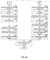
- FIG. 12 provides a logic flow diagram illustrating one embodiment of equalizing received RF burst(s). This involves a step 6 1200 receiving a number of burst(s), which are then de-rotated as previously described in step 1202. In step 1204, processing the RF burst(s) with a first equalizer, such as the first equalizer processing branch, of FIG. 9 which is trained using the known training sequence in step 1206. The received RF bursts may be supplied to both the first equalizer processing branch and second equalizer processing branch. Within the second equalizer processing branch, a buffer of other memory loeation stores the received RF burst(s), for further processing.
- a first equalizer such as the first equalizer processing branch
- the first equalizer processing branch equalizes the received RF burst in step 1208 using filters that have been trained based on a known training sequence.
- This equalized RF burst produces a series of samples or soft decisions which are de-interleaved in step 1210 and decoded in step 1212 to yield extracted data bits.
- a data frame may be decoded from the extracted data bits in step 1214, which in turn may be re-encoded to produce re-encoded data bits in step 1216. In the case of a voice frame, this requires that the data from the current set of RF burst(s) be combined with that of a previous set of RF bursts to produce a valid voice frame.
- the voice frame may them be re-encoded to produce re-encoded data bits.
- the re-encoded data bits may be interleaved in step 1218 to produce a re-encoded data burst.
- This re-encoded data burst may comprise partially re-encoded bits when applied to voice frames.
- Step 1220 retrieves RF burst(s) from memory for processing using a second equalizer processing branch. This may involve the retrieval of one or more RF bursts, which are processed using the second equalizer branch.
- the re-encoded data burst is provided as a signal to train the second equalizer processing branch in step 1222. This allows the RF burst stored in memory to be equalized in step 1224 using the second equalizer processing branch, wherein the second equalizer processing branch is trained not only on the known training sequence, but also at least some partially re-encoded data bits produced from the original output of the channel decoder.
- the second equalizer processing branch produces an alternate set of soft decisions, which may be de-interleaved in step 1226 and decoded in step 1228 in order to produce an alternate date frame in step 1230.
- the single antenna interface cancel action may perform worse than the conventional receiver.
- channels having long delays such as those having hilly terrain can also cause large degradation due to the short pre-filter length.
- a switch function may be added to enable the interactive single antenna cancellation process.
- the switch may be based on any combination of SNR, Colored noise discriminator and Channel profile detector.
- the present invention provides a multi-branch equalizer processing module operable to cancel interference associated with received radio frequency (RF) burst(s).
- This multi-branch equalizer processing module includes both a first equalizer processing branch and a second equalizer processing branch.
- the first equalizer processing branch is operable to be trained based upon known training sequences and equalize the received RF burst. This results in soft samples or decisions which in turn may be converted to data bits.
- the soft samples are processed with a de-interleaver and channel decoder, where the combination is operable to produce a decoded frame of data bits from the soft samples.
- a re-encoder may re-encode the decoded frame to produce re-encoded or at least partially re-encoded data bits.
- An interleaver then processes the at least partially re-encoded data bits to produce and at least partially re-encoded burst.
- the second equalizer processing branch uses the at least partially re-encoded data bits to train linear equalizer(s) within the second equalizer processing branch.
- a buffer may initially store the received RF burst(s), which are retrieved and equalized by the second equalizer processing branch once the linear equalizer(s) are trained. This results in alternate soft samples or decisions which in turn may be converted to alternate data bits.
- the alternate soft samples are processed with the de-interleaver and channel decoder, where the combination is operable to produce an alternate decoded frame of data bits from the alternate soft samples. This allows interfering signals to be cancelled and more accurate processing of the received RF bursts to occur.
- the term “substantially” or “approximately”, as may be used herein, provides an industry-accepted tolerance to its corresponding term. Such an industry-accepted tolerance ranges from less than one percent to twenty percent and corresponds to, but is not limited to, component values, integrated circuit process variations, temperature variations, rise and fall times, and/or thermal noise.
- the term “operably coupled”, as may be used herein, includes direct coupling and indirect coupling via another component, element, circuit, or module where, for indirect coupling, the intervening component, element, circuit, or module does not modify the information of a signal but may adjust its current level, voltage level, and/or power level.
- inferred coupling includes direct and indirect coupling between two elements in the same manner as “operably coupled”.
- the term "compares favorably”, as may be used herein indicates that a comparison between two or more elements, items, signals, etc., provides a desired relationship. For example, when the desired relationship is that signal 1 has a greater magnitude than singal 2, a favorable comparison may be achieved when the magnitude of signal 1 is greater than that of signal 2 or when the magnitude of signal 2 is less than that of signal 1.
Abstract
Description
- This application claims the benefit of priority to and incorporates herein by reference in its entirety for all purposes, U.S. Provisional Patent Application No. 60/657,564 entitled "SINGLE ANTENNA INTERFERENCE CANCELLATION IN A CELLULAR TELEPHONE," by Hanks Zeng, et al. filed on March 1, 2005. This application also claims the benefit of priority to and incorporates herein by reference in its entirety for all purposes, U.S. Provisional Patent Application No. 60/678,997 entitled "EQUALIZER TRAINING METHOD USING RE-ENCODED BITS AND KNOWN TRAINING SEQUENCES", by Yue Chen, et al, filed on May 9, 2005. This application also claims the benefit of priority to and incorporates herein by reference in its entirety for all purposes, U.S. Provisional Patent Application No. 60/603,148 entitled "METHOD AND SYSTEM IMPROVING RECEPTION IN WIRED AND WIRELESS RECEIVERS THROUGH REDUNDANCY," by Arie Heiman, et al. filed on August 20, 2004.
- The present invention relates generally to cellular wireless communication systems, and more particularly to the cancellation of interference associated with received data communications processed by a wireless terminal within a wireless communication system.
- Cellular wireless communication systems support wireless communication services in many populated areas of the world. While cellular wireless communication systems were initially constructed to service voice communications, they are now called upon to support data communications as well. The demand for data communication services has exploded with the acceptance and widespread use of the Internet. While data communications have historically been serviced via wired connections, cellular wireless users now demand that their wireless units also support data communications. Many wireless subscribers now expect to be able to "surf" the Internet, access their email, and perform other data communication activities using their cellular phones, wireless personal data assistants, wirelessly linked notebook computers, and/or other wireless devices. The demand for wireless communication system data communications continues to increase with time. Thus, existing wireless communication systems are currently being created/modified to service these burgeoning data communication demands.
- Cellular wireless networks include a "network infrastructure" that wirelessly communicates with wireless terminals within a respective service coverage area. The network infrastructure typically includes a plurality of base stations dispersed throughout the service coverage area, each of which supports wireless communications within a respective cell (or set of sectors). The base stations couple to base station controllers (BSCs), with each BSC serving a plurality of base stations. Each BSC couples to a mobile switching center (MSC). Each BSC also typically directly or indirectly couples to the Internet.
- In operation, each base station communicates with a plurality of wireless terminals operating in its cell/sectors. A BSC coupled to the base station routes voice communications between the MSC and the serving base station. The MSC routes the voice communication to another MSC or to the PSTN. BSCs route data communications between a servicing base station and a packet data network that may include or couple to the Internet. Transmissions from base stations to wireless terminals are referred to as "forward link" transmissions while transmissions from wireless terminals to base stations are referred to as "reverse link" transmissions.
- Wireless links between base stations and their serviced wireless terminals typically operate according to one (or more) of a plurality of operating standards. These operating standards define the manner in which the wireless link may be allocated, setup, serviced, and torn down. One popular cellular standard is the Global System for Mobile telecommunications (GSM) standard. The GSM standard, or simply GSM, is predominant in Europe and is in use around the globe. While GSM originally serviced only voice communications, it has been modified to also service data communications. GSM General Packet Radio Service (GPRS) operations and the Enhanced Data rates for GSM (or Global) Evolution (EDGE) operations coexist with GSM by sharing the channel bandwidth, slot structure, and slot timing of the GSM standard. The GPRS operations and the EDGE operations may also serve as migration paths for other standards as well, e.g., IS-136 and Pacific Digital Cellular (PDC).
- In order for EDGE to provide increased data rates within a 200 KHz GSM channel, it employs a higher order modulation, 8-PSK (octal phase shift keying), in addition to GSM's standard Gaussian Minimum Shift Keying (GMSK) modulation. EDGE allows for nine different (autonomously and rapidly selectable) air interface formats, known as Modulation and Coding schemes (MCSs), with varying degrees of error control protection. Low MCS modes, (MCS 1-4) use GMSK (low data rate) while high MCS modes (MCS 5-9) use 8-PSK (high data rate) modulation for over the air transmissions, depending upon the instantaneous demands of the application.
- To a cellular telephone operating in a receive mode, co-channel and adjacent channel GMSK/8PSK signals appear as colored noise. In order to better receive the information intended for the cellular telephone, the cellular telephone must attempt to cancel these interference signals. Prior techniques for canceling such interference included channel equalization for received symbols. However, existing channel equalization techniques fail to typically remove co-channel and adjacent channel noise sufficiently. Thus, a need exists for improvements in interference cancellation.
- The present invention is directed to apparatus and methods of operation that are further described in the following Brief Description of the Drawings, the Detailed Description of the Invention, and the claims.
According to an aspect of the invention, a multi-branch equalizer processing module operable to cancel interference associated with received radio frequency (RF) burst(s) is provided, comprising: - a first equalizer processing branch operable to:
- be trained based upon known training sequence(s);
- equalize the received RF burst(s); and
- extract data bits from the received RF burst(s);
- a second equalizer processing branch operable to:
- be trained based upon the known training sequence(s) and re-encoded data bits, wherein the re-encoded data bits are produced by processing a decoded frame;
- equalize the received RF burst(s); and
- extract alternate data bits from the received RF burst(s).
- a deinterleaver; and
- a channel decoder, wherein the combination of the deinterleaver and channel decoder operably coupled to the first equalizer processing branch and the second equalizer processing branch and is operable to:
- decode the frame comprised the extracted data bits; and
- decode an alternative frame comprised of at least some of the alternate data bits.
- the first equalizer processing branch comprises:
- an I,Q interference cancellation portion; and
- a decision feedback equalizer portion; and
- the second equalizer processing branch comprises:
- an I,Q interference cancellation portion; and
- a linear equalizer portion.
- an encoder; and
- an interleaver, wherein the combination of the encoder and interleaver, wherein the combination is operable to:
- process the decoded frame to produce the re-encoded data bits; and
- provide a training signal to the second equalizer processing branch, wherein the training signal operable to be used to train the second equalizer training branch based upon the known training sequence(s) and re-encoded data bits.
- a Radio Frequency (RF) front end operable to receive RF burst(s);
- a baseband processor communicatively coupled to the RF front end, wherein the baseband processor and RF front end are operable to produce a baseband signal from the RF burst(s); and
- a multi-branch equalizer processing module operably coupled to the baseband processor, wherein the multi-branch equalizer processing module further comprises:
- an equalizer interface that receives the baseband signal from the baseband processor, and outputs soft decisions;
- a first equalizer processing branch operable to:
- be trained based upon known training sequence(s);
- equalize the received RF burst(s); and
- extract data bits from the received RF burst(s);
- a second equalizer processing branch operable to:
- be trained based upon an at least partially re-encoded burst comprising the known training sequence(s) and re-encoded data bits, wherein the at least partially re-encoded burst are produced by processing a decoded frame;
- equalize the received RF burst(s); and
- extract alternate data bits from the received RF burst(s);
- produce a data block from the soft decisions or alternative soft decisions;
- deinterleave the data block; and
- decode a frame from the data block;
- re-encode the data frame to produce at least a partially re-encoded data block; and
- interleave the at least partially re-encoded data block to produce the at least partially re-encoded burst.
- the first equalizer processing branch comprises:
- an I,Q interference cancellation portion; and
- a decision feedback equalizer portion; and
- the second equalizer processing branch comprises:
- an I,Q interference cancellation portion; and
- a linear equalizer portion.
- an encoder; and
- an interleaver, wherein the combination of the encoder and interleaver, wherein the combination is operable to:
- re-encode the data frame to produce the at least a partially re-encoded data block; and
- interleave the at least partially re-encoded data block to produce the at least partially re-encoded burst.
- receiving the RF burst(s);
- decoding known training sequence(s) from the received RF burst(s);
- training a first equalizer based on the decoded known training sequence(s);
- equalizing the received RF burst(s) with the first equalizer processing branch;
- deinterleaving the RF burst(s);
- decoding the RF burst(s) to yield extracted soft samples;
- decoding data bits from the extracted soft samples;
- re-encoding the data bits to produce at least partially re-encoded soft samples;
- interleaving the at least partially re-encoded soft samples to produce an at least partially re-encoded burst;
- retrieving the received RF burst(s) from memory for a second equalizer processing branch;
- training the second equalizer processing branch with the at least partially re-encoded burst;
- equalizing the received RF burst(s) in memory with the second equalizer;
- deinterleaving the RF burst(s);
- decoding the RF burst(s) to yield alternative soft samples; and
- decoding alternative data bits from the alternative soft samples.
- the first equalizer processing branch processes a first set of 4 RF bursts to yield the frame; and
- the second equalizer processing branch processes the first set of 4 RF bursts in memory to yield the alternative data bits.
- the first equalizer processing branch processes a first set of 4 RF bursts to yield the frame; and
- the second equalizer processing branch processes a second set of 4 RF bursts in memory to yield the alternative data bits, and wherein the first set of 4 RF bursts preceded the second set of 4 RF bursts.
- the first equalizer processing branch comprises a 4-tap pre-filter and MLSE; and
- the second equalizer comprises a 7-tap linear equalizer.
- For a more complete understanding of the present invention and the advantages thereof, reference is now made to the following description taken in conjunction with the accompanying drawings in which like reference numerals indicate like features and wherein:
- FIG. 1 is a system diagram illustrating a portion of a cellular wireless communication system that supports wireless terminals operating according to the present invention;
- FIG. 2 is a block diagram functionally illustrating a wireless terminal constructed according to the present invention;
- FIG. 3 is a block diagram illustrating the general structure of a GSM frame and the manner in which data blocks are carried by the GSM frame;
- FIG. 4 is a block diagram illustrating the formation of down link transmissions;
- FIG. 5 is a block diagram illustrating the stages associated with recovering a data block from a series of RF bursts;
- FIG. 6 is a block diagram illustrating the stages associated with recovering a voice data from a series of RF bursts;
- FIG. 7 is a block diagram illustrating the stages associated with recovering a burst from a data or voice frame;
- FIGs. 8A and 8B are flow charts illustrating operation of a wireless terminal in receiving and processing a RF burst;
- FIG. 9 is a block diagram illustrating components of a multi-branch burst equalization component according to an embodiment of the present invention; and
- FIG. 10 is a block diagram illustrating components of a burst equalization component according to an embodiment of the present invention; and
- FIG. 11 is a block diagram illustrating components of a burst equalization component according to an embodiment of the present invention; and
- FIG. 12 is a flow chart illustrating operation according to an embodiment of the present invention.
- Preferred embodiments of the present invention are illustrated in the FIGs., like numerals being used to refer to like and corresponding parts of the various drawings.
- Gaussian Minimum Shift Keying (GMSK) modulation systems can be modeled as a single-input two-output system in real domain. This model is a virtual single transmit 2 receive system. Interference cancellation techniques for multiple antennas can be applied to GMSK systems as provided by embodiments of the present invention that substantially addresses the above identified needs as well as other needs. The present invention provides a multi-branch equalizer processing module operable to cancel interference associated with received radio frequency (RF) burst(s). This multi-branch equalizer processing module includes multiple equalizer processing branches. One equalizer processing branch is operable to be trained based upon known training sequences and equalize the received RF burst. These results are then further processed and used to train a second equalizer processing branch. The second equalizer processing branch then equalizes the received RF burst to produce an output based on canceling the interfering signals that results in improved processing of the received RF bursts.
- FIG. 1 is a system diagram illustrating a portion of a cellular
wireless communication system 100 that supports wireless terminals operating in accordance with embodiments of the present invention. Cellularwireless communication system 100 includes a Mobile Switching Center (MSC) 101, Serving GPRS Support Node/Serving EDGE Support Node (SGSN/SESN) 102, base station controllers (BSCs) 152 and 154, andbase stations SESN 102 couples to theInternet 114 via a GPRS Gateway Support Node (GGSN) 112. Aconventional voice terminal 121 couples to thePSTN 110. A Voice over Internet Protocol (VoIP)terminal 123 and apersonal computer 125 couple to theInternet 114. TheMSC 101 couples to the Public Switched Telephone Network (PSTN) 110. - Each of the base stations 103-106 services a cell/set of sectors within which it supports wireless communications. Wireless links that include both forward link components and reverse link components support wireless communications between the base stations and their serviced wireless terminals. These wireless links can result in co-channel and adjacent channel signals that may appear as noise which may be colored or white. As previously stated, this noise may interfere with the desired signal of interest. Hence, the present invention provides techniques for canceling such interference in poor signal-to-noise ratio (SNR) or low signal-to-interference ratio (SIR) environments.
- These wireless links may support digital data communications, VoIP communications, and other digital multimedia communications. The cellular
wireless communication system 100 may also be backward compatible in supporting analog operations as well. The cellularwireless communication system 100 may support the Global System for Mobile telecommunications (GSM) standard and also the Enhanced Data rates for GSM (or Global) Evolution (EDGE) extension thereof. The cellularwireless communication system 100 may also support the GSM General Packet Radio Service (GPRS) extension to GSM. However, the present invention is also applicable to other standards as well, e.g., TDMA standards, CDMA standards, etc. In general, the teachings of the present invention apply to digital communication techniques that address the identification and cancellation of interfering communications. -
Wireless terminals wireless communication system 100 via wireless links with the base stations 103-106. As illustrated, wireless terminals may includecellular telephones laptop computers desktop computers 124 and 126, anddata terminals wireless communication system 100 supports communications with other types of wireless terminals as well. As is generally known, devices such aslaptop computers desktop computers 124 and 126,data terminals cellular telephones Internet 114, transmit and receive data communications such as email, transmit and receive files, and to perform other data operations. Many of these data operations have significant download data-rate requirements while the upload data-rate requirements are not as severe. Some or all of the wireless terminals 116-130 are therefore enabled to support the EDGE operating standard. These wireless terminals 116-130 also support the GSM standard and may support the GPRS standard. - FIG. 2 is a block diagram functionally illustrating
wireless terminal 200. Thewireless terminal 200 of FIG. 2 includes anRF transceiver 202,digital processing components 204, and various other components contained within a housing. Thedigital processing components 204 includes two main functional components, a physical layer processing, speech COder/DECoder (CODEC), and baseband CODECfunctional block 206 and a protocol processing, man-machine interfacefunctional block 208. A Digital Signal Processor (DSP) is the major component of the physical layer processing, speech COder/DECoder (CODEC), and baseband CODECfunctional block 206 while a microprocessor, e.g., Reduced Instruction Set Computing (RISC) processor, is the major component of the protocol processing, man-machine interfacefunctional block 208. The DSP may also be referred to as a Radio Interface Processor (RIP) while the RISC processor may be referred to as a system processor. However, these naming conventions are not to be taken as limiting the functions of these components. -
RF transceiver 202 couples to anantenna 203, to thedigital processing components 204, and also tobattery 224 that powers all components ofwireless terminal 200. The physical layer processing, speech COder/DECoder (CODEC), and baseband CODECfunctional block 206 couples to the protocol processing, man-machine interfacefunctional block 208 and to a coupledmicrophone 226 andspeaker 228. The protocol processing, man-machine interfacefunctional block 208 couples to various components such as, but not limited to, Personal Computing/DataTerminal Equipment interface 210,keypad 212, Subscriber Identification Module (SIM)port 213, acamera 214,flash RAM 216,SRAM 218,LCD 220, and LED(s) 222. Whencamera 214 andLCD 220 are present, these components may support either/both still pictures and moving pictures. Thus, thewireless terminal 200 of FIG. 2 may be operable to support video services as well as audio services via the cellular network. - FIG. 3 is a block diagram illustrating the general structure of a GSM frame and the manner in which data blocks are carried by the GSM frame. The GSM frame, 20 ms in duration, is divided into quarter frames, each of which includes eight time slots, time slots 0 through 7. Each time slot is approximately 625 us in duration, includes a left side, a right side, and a midamble. The left side and right side of an RF burst of the time slot carry data while the midamble is a training sequence.
- RF bursts of four time slots of the GSM frame carry a segmented RLC block, a complete RLC block, or two RLC blocks, depending upon a supported Modulation and Coding Scheme (MCS) mode. For example, data block A is carried in slot 0 of
quarter frame 1, slot 0 ofquarter frame 2, slot 0 ofquarter frame 3, and slot 0 ofquarter frame 3. Data block A may carry a segmented RLC block, an RLC block, or two RLC blocks. Likewise, data block B is carried inslot 1 ofquarter frame 1,slot 1 ofquarter frame 2,slot 1 ofquarter frame 3, andslot 1 ofquarter frame 3. The MCS mode of each set of slots, i.e., slot n of each quarter frame, for the GSM frame is consistent for the GSM frame but may vary from GSM frame to GSM frame. Further, the MCS mode of differing sets of slots of the GSM frame, e.g., slot 0 of each quarter frame vs. any of slots 1-7 of each quarter frame, may differ. The RLC block may carry voice data or other data. - FIG. 4 generally depicts the various stages associated with mapping data into RF bursts. Data is initially uncoded and maybe accompanied by a data block header. Block coding operations perform the outer coding for the data block and support error detection/correction for data block. The outer coding operations typically employ a cyclic redundancy check (CRC) or a Fire Code. The outer coding operations are illustrated to add tail bits and/or a Block Code Sequence (BCS), which is/are appended to the data. In CS-1, the header and data are coded together using block coding and convolutional coding. In non-CS-1 coding schemes, the header and data information are often coded separately.
- Fire codes allow for either error correction or error detection. Fire Codes are a shortened binary cyclic code that appends redundancy bits to bits of the data Header and Data. The pure error detection capability of Fire Coding may be sufficient to let undetected errors go through with only a probability of 2-40. After block coding has supplemented the Data with redundancy bits for error detection, calculation of additional redundancy for error correction to correct the transmissions caused by the radio channels. The internal error correction or coding scheme is based on convolutional codes.
- Some redundant bits generated by the convolutional encoder may be punctured prior to transmission. Puncturing increases the rate of the convolutional code and reduces the redundancy per data block transmitted. Puncturing additionally lowers the bandwidth requirements such that the convolutional encoded signal fits into the available channel bit stream. The convolutional encoded punctured bits are passed to an interleaver, which shuffles various bit streams and segments the interleaved bit streams into the 4 bursts shown.
- FIG. 5 is a block diagram that generally depicts the various stages associated with recovering a data block from a RF burst(s). Four RF bursts typically make up a data block. These bursts are received and processed. Once all four RF bursts have been received, the RF bursts are combined to form an encoded data block. The encoded data block is then depunctured (if required), decoded according to an inner decoding scheme, and then decoded according to an outer decoding scheme. The decoded data block includes the data block header and the data. Depending on how the data and header are coded, partial decoding may be possible to identify data
- FIG. 6 is a block diagram that depicts the various stages associated with recovering data from a transmitted voice frame. This is similar to the process described with reference to FIG. 5. Typically a 20 millisecond voice frame is transmitted, wherein the first half of the 20 millisecond voice frame is transmitted within a first series of RF bursts and the second half of the voice frame is transmitted with a second series of RF bursts. A series of four RF bursts is shown as being off-set by 10 milliseconds from the first voice frame, Voice Framen, wherein the second half of Voice Framen and the first half of the subsequent voice frame, Voice Framen+1, are coded and interleaved into the series of four RF bursts. When the four RF bursts are processed, the coded block produced produces a data stream that comprises the second half of Voice Framen and the first half of Voice Framen+1. The first half of Voice Framen, stored within memory, may be combined with the second half of Voice Framen to produce the data associated with a valid Voice Framen.
- Re-encoding the data associated with a valid Voice Framen, as described with reference to FIG. 7, may result in an at least partially re-encoded data bursts that may be used to train the second equalizer processing branch. As previously stated, the first half of the voice frame recovered from a previous set of RF bursts and the second half of the voice frame recovered from the current set of RF bursts are combined to produce the data associated with a voice frame. This voice frame may be validated and corrected using cycle redundancy checks in order to produce a valid voice frame. This valid voice frame may then be re-encoded. However, only the second half of the re-encoded Voice Framen is used to partially recreate the burst(s). The second half of re-encoded Voice Framen may be segmented and interleaved to produce a series of partially encoded RF bursts. Since the processing of the second half of the Voice Framen+1 has not occurred, the RF bursts are only partially re-encoded. Since Voice Framen+1 has not been validated, the first half of a re-encoded Voice Framen+1 is not possible and is not used to recreate the burst(s). The partially re-encoded burst(s), based on Voice Framen, taken together with the known training sequences are operable to better train the second equalizer-processing branch in accordance with an embodiment of the present invention.
- FIGs. 8A and 8B are flow charts illustrating operation of a
wireless terminal 200 in receiving and processing a RF burst. The operations illustrated in FIGs. 8A and 8B correspond to a single RF burst in a corresponding slot of GSM frame. The RF front end, the baseband processor, and the equalizer processing module perform these operations. These operations are generally called out as being performed by one of these components. However, the split of processing duties among these various components may differ without departing from the scope of the present invention. - Referring particular to FIG. 8A, operation commences with the RF front end receiving an RF burst in a corresponding slot of a GSM frame (step 802). The RF front end then converts the RF burst to a baseband signal (step 804). Upon completion of the conversion, the RF front end sends an interrupt to the baseband processor (step 806). Thus, as referred to in FIG. 8A, the RF front end performs steps 802-806.
- Operation continues with the baseband processor receiving the baseband signal (step 808). In a typical operation, the RF front end, the baseband processor, or modulator/demodulator will sample the analog baseband signal to digitize the baseband signal. After receipt of the baseband signal (in a digitized format), the baseband processor performs blind detection of a modulation format of the baseband signal of
step 810. This blind detection of the modulation format determines the modulation format of the corresponding baseband signal. In one particular embodiment according to the GSM standard, the modulation format will be either Gaussian Minimum Shift Keying (GMSK) modulation or Eight Phase Shift Keying (8PSK) modulation. The baseband processor makes the determination (step 812) and proceeds along one of two branches based upon the detected modulation format. - For GMSK modulation, the baseband processor performs de-rotation and frequency correction of the baseband signal at
step 814. Next, the baseband processor performs burst power estimation of the baseband signal atstep 816. Referring now to FIG. 11 via off page connector A, the baseband processor next performs timing, channel, noise, and signal-to-noise ratio (SNR) estimation atstep 820. Subsequently, the baseband processor performs automatic gain control (AGC) loop calculations (step 822). Next, the baseband processor performs soft decision scaling factor determination on the baseband signal (step 824). Afterstep 824, the baseband processor performs matched filtering operations on the baseband signal atstep 826. - Steps 808-826 are referred to hereinafter as pre-equalization processing operations. With the baseband processor performing these pre-equalization processing operations on the baseband signal it produces a processed baseband signal. Upon completion of these pre-equalization processing operations, the baseband prucessor issues a command to the equalizer module.
- The equalizer module, whose operation as a multi-branch equalizer will be discussed in further detail with reference to FIG. 9 and following, upon receiving the command, prepares to equalize the processed baseband signal based upon the modulation format, e.g., GMSK modulation or 8PSK modulation. The equalizer module receives the processed baseband signal, settings, and/or parameters from the baseband processor and performs Maximum Likelihood Sequence Estimation (MLSE) equalization on the left side of the baseband signal at
step 828. As was shown previously with reference to FIG. 3, each RF burst contains a left side of data, a midamble, and a right side of data. Typically, atstep 828, the equalizer module equalizes the left side of the RF burst to produce soft decisions for the left side. Then, the equalizer module equalizes the right side of the processed baseband signal atstep 830. The equalization of the right side produces a plurality of soft decisions corresponding to the right side. The burst equalization is typically based of known training sequences within the bursts. However, the embodiments of the present invention may utilize re-encoded or partially re-encoded data to improve the equalization process. This may take the form of an iterative process wherein a first branch performs burst equalization and a second module performs a second equalization based on the result obtained with the first branch over a series of RF bursts. - The equalizer module then issues an interrupt to the baseband processor indicating that the equalizer operations are complete for the RF burst. The baseband processor then receives the soft decisions from the equalizer module. Next, the baseband processor determines an average phase of the left and right sides based upon the soft decisions received from the equalizer module at
step 832. The baseband processor then performs frequency estimation and tracking based upon the soft decisions received from the equalizer module atstep 836. The operations ofstep 832, or step 854 and step 836 are referred to herein as "post-equalization processing." After operation atstep 836, processing of the particular RF burst is completed. - Referring again to FIG. 8A, the baseband processor and equalizer module take the right branch from
step 812 when an 8PSK modulation is blindly detected atstep 810. In the first operation for 8PSK modulation, the baseband processor performs de-rotation and frequency correction on the baseband signal atstep 818. The baseband processor then performs burst power estimation of the baseband singal atstep 820. Referring now to FIG. 8B via off page connector B, operation continues with the baseband processor performing timing, channel, noise, and SNR estimations atstep 840. The baseband processor then performs AGC loop calculations on the baseband signal atstep 842. Next, the baseband processor calculates Decision Feedback Equalizer (DFE) coefficients that will be used by the equalizer module atstep 844. The process to produce these coefficients will be described in further detail This determination when using a multi-branch equalizer will be discussed with reference to FIG. 9 and following. The baseband processor then performs pre-equalizer operations on the baseband signal atstep 846. Finally, the baseband processor determines soft decision scaling factors for the baseband signal atstep 848. Steps 818-848 performed by the baseband processor 30 are referred to herein as ''pre-equalization processing" operations for an 8PSK modulation baseband signal. Upon completion of step 648, the baseband processor issues a command to equalizer module to equalize the processed baseband signal. - Upon receipt of the command from the baseband processor, the equalizer module receives the processed baseband signal, settings, and/or parameters from the baseband processor and commences equalization of the processed baseband signal. The equalizer module first prepares state values that it will use in equalizing the 8PSK modulated processed baseband signal at
step 850. In the illustrated embodiment, the equalizer module uses a Maximum A posteriori Probability (MAP) equalizer. The equalizer module then equalizes the left and right sides of the processed baseband signal using the MAP equalizer to produce soft decisions for the processed baseband signal atstep 852. Upon completion ofstep 854, the equalizer module issues an interrupt to the baseband processor indicating its completion of the equalizing the processed baseband signal corresponding. - The baseband processor then receives the soft decisions from the equalizer module. Next, the baseband processor determines the average phase of the left and right sides of the processed baseband signal based upon the soft decisions (step 854). Finally, the baseband processor performs frequency estimation and tracking for the soft decisions (step 836). The operations of
steps step 836, operation is complete for the particular RF burst depicts the various stages associated with recovering a data block from an RF Burst. - While the operations of FIGs. 8A and 8B are indicated to be performed by particular components of the wireless terminal, such segmentation of operations could be performed by differing components. For example, the equalization operations could be performed by the baseband processor or system processor in other embodiments. Further, decoding operations could also be performed by the baseband processor or the system processor in other embodiments.
- FIG. 9 is a block diagram illustrating the structure of one embodiment of a multi-branch
equalizer processing module 900 operable to perform single antenna interference cancellation (SAIC) in accordance with embodiments of the present invention. There are two types of SAIC equalizer methods: (1) joint-detection (JD); and (2) blind interference cancellation (BIC). According to one aspect of the present invention, BIC method is selected. The components illustrated in FIG. 9 may be hardware components, software components executed by a processor, e.g., 206 or 208 of FIG. 2, or a combination of hardware components and software components. Multi-branchequalizer processing module 900 includes a firstequalizer processing branch 902 and secondequalizer processing branch 904.Derotation block 906 receives In phase (I) and Quadrature (Q) components of a baseband burst. This baseband burst corresponds to RF burst(s), which were described with reference to FIGs. 3-7. Derotation block 906 derotates received I and Q burst samples and produces I and Q burst samples ("bursts"). In one embodiment, firstequalizer processing branch 902 may include a burst equalizer. These samples may be later equalized in accordance with the embodiments of the present invention with other samples making up a data packet, e.g., RLC packet. The iterative processes of the second equalizer processing branch may be performed in addition to the burst level equalization during certain operating conditions. - Burst equalizers, include I and Q Finite Impulse Response (FIR) filters 908 and 910 and Minimum Least Squares Estimation (MLSE)
equalizer 912 that operate upon each burst received fromderotation block 906. These components are trained bytraining module 913 using known Training Sequence(s) (TS), within the midamble received with each burst. Alternately, these components could be trained over multiple bursts. Firstequalizer processing branch 902 produces soft decisions wherein multiple soft decisions represent each data bit prior to decoding. Each soft sample is provided to deinterleaver 914 which in turn provides the deinterleaved soft samples tochannel decoder 916.Channel decoder 916 decodes a data frame from the soft samples (i.e. the multiple soft sample(s) that represent each data bit are decoded by the channel decoder to produce hard bits after decoding). - The data frame produced by
channel decoder 916 may be validated and re-encoded using re-encoder 918 in order to produce re-encoded data bits.Interleaver 920 receives the re-encoded data bits to produce a re-encoded data burst(s). The re-encoded data burst(s), along with known training sequence(s), may then be used to train second equalizer processing branch 310. - Second
equalizer processing branch 906 includes abuffer 922 operable to store multiple bursts in memory as well as an I and Q FIR filters 924 and 926, respectively. I andQ filters training module 928 using known training sequence and at least partially re-encoded bursts. In this way, the second equalizer processing branch takes at least partially re-encoded data and known training sequences to train the I and Q RF filters. This results in an improved SNR for the burst(s) processed frombuffer 922. After the I and Q filters have been trained and used to process the stored burst(s). The results are combined withadder 930. This creates an alternate set of soft samples which are provided todeinterleaver 914 andchannel Decoder 916 to produce an alternate set of data bits. - FIG. 10 may be used to describe the first branch of the multi-branch equalizer of FIG. 9 in more detail. Since there are only 26 training symbols, the first processing branch as shown may train feed-
forward filters - FIG. 11 may be used to describe the second branch of the multi-branch equalizer of FIG. 9 in more detail. After channel decoding, the data is re-encoded and used to train 7
tap LEs - The following discussion further describes the indirect training method that may be based on the least-square channel estimation (LS-CE) and is similar to that used in EDGE. First the channel is estimated using the training sequence. Then the pre-filter and MLSE parameters are calculated as if they are the feed-forward and feedback filters of a DFE. A problem of the indirect method is poor CE since SAIC is usually operated at low SIR. The CE error propagates in the calculation filter coefficients.
- The signal model at the MLSE input in FIG. 10 can be viewed as an ISI channel plus noise. Suppose the DFE feedback filter impulse response is {b(0),b(1),...,b(Lb-1)}. The objective of training is to obtain pre-filter coefficients {f1(0),...f1(Lf-1), f2(0),...f2(Lf-1)}, and the MLSE parameters b for the given training symbols and corresponding received signal.
- Based on above mode, the noise at the MLSE input is given by

where X1 and X2 are de-rotation output I & Q, respectively, s is the training symbol, d is the system delay. In vector form:


- Since the number of training symbols is limited, joint optimization of f and b is sensitive to noise. The following discussion derives a sub-optimal approach that reduces the estimated parameter to pre-filer f only.
- Cross-correlation between the pre-filter outputs (X f ) and training symbol may be by the ISI channel at the MLSE input (b). Thus b can be represented by f. Using LS CE at the pre-filter output, and let b be the channel estimate provides:

where ()+ represents the pseudo-inverse. Substituting above will minimization the function, to yield:
where A = X'(I- S S + )X , and ()' is the transpose operation. To avoid trivial solution, constraints are applied. Two types commonly used constraints are Unit-norm constraint and the Linear constraint. When this constrains the norm of 1, then the optimization solution is the eigen-vector of A corresponding to the least eigenvalue Provides:


- FIG. 11 may be used to describe the second branch of the multi-branch equalizer of FIG. 9 in more detail. After channel decoding, the data is re-encoded and used to train 7
tap LEs - FIG. 12 provides a logic flow diagram illustrating one embodiment of equalizing received RF burst(s). This involves a
step 6 1200 receiving a number of burst(s), which are then de-rotated as previously described instep 1202. Instep 1204, processing the RF burst(s) with a first equalizer, such as the first equalizer processing branch, of FIG. 9 which is trained using the known training sequence instep 1206. The received RF bursts may be supplied to both the first equalizer processing branch and second equalizer processing branch. Within the second equalizer processing branch, a buffer of other memory loeation stores the received RF burst(s), for further processing. The first equalizer processing branch equalizes the received RF burst instep 1208 using filters that have been trained based on a known training sequence. This equalized RF burst produces a series of samples or soft decisions which are de-interleaved instep 1210 and decoded instep 1212 to yield extracted data bits. A data frame may be decoded from the extracted data bits instep 1214, which in turn may be re-encoded to produce re-encoded data bits instep 1216. In the case of a voice frame, this requires that the data from the current set of RF burst(s) be combined with that of a previous set of RF bursts to produce a valid voice frame. The voice frame may them be re-encoded to produce re-encoded data bits. The re-encoded data bits may be interleaved instep 1218 to produce a re-encoded data burst. This re-encoded data burst may comprise partially re-encoded bits when applied to voice frames. -
Step 1220 retrieves RF burst(s) from memory for processing using a second equalizer processing branch. This may involve the retrieval of one or more RF bursts, which are processed using the second equalizer branch. The re-encoded data burst is provided as a signal to train the second equalizer processing branch instep 1222. This allows the RF burst stored in memory to be equalized instep 1224 using the second equalizer processing branch, wherein the second equalizer processing branch is trained not only on the known training sequence, but also at least some partially re-encoded data bits produced from the original output of the channel decoder. This allows the second processing branch to provide an improved output over the first processing branch by utilizing not only the known training sequence but also re-encoded data bits in order to better equalize or train the second equalizer processing branch. The second equalizer processing branch produces an alternate set of soft decisions, which may be de-interleaved instep 1226 and decoded instep 1228 in order to produce an alternate date frame instep 1230. - In noise-limited scenarios, the single antenna interface cancel action may perform worse than the conventional receiver. In addition, channels having long delays such as those having hilly terrain can also cause large degradation due to the short pre-filter length. To solve the problem, a switch function may be added to enable the interactive single antenna cancellation process. The switch may be based on any combination of SNR, Colored noise discriminator and Channel profile detector.
- In summary, the present invention provides a multi-branch equalizer processing module operable to cancel interference associated with received radio frequency (RF) burst(s). This multi-branch equalizer processing module includes both a first equalizer processing branch and a second equalizer processing branch. The first equalizer processing branch is operable to be trained based upon known training sequences and equalize the received RF burst. This results in soft samples or decisions which in turn may be converted to data bits. The soft samples are processed with a de-interleaver and channel decoder, where the combination is operable to produce a decoded frame of data bits from the soft samples. A re-encoder may re-encode the decoded frame to produce re-encoded or at least partially re-encoded data bits. An interleaver then processes the at least partially re-encoded data bits to produce and at least partially re-encoded burst. The second equalizer processing branch uses the at least partially re-encoded data bits to train linear equalizer(s) within the second equalizer processing branch. A buffer may initially store the received RF burst(s), which are retrieved and equalized by the second equalizer processing branch once the linear equalizer(s) are trained. This results in alternate soft samples or decisions which in turn may be converted to alternate data bits. The alternate soft samples are processed with the de-interleaver and channel decoder, where the combination is operable to produce an alternate decoded frame of data bits from the alternate soft samples. This allows interfering signals to be cancelled and more accurate processing of the received RF bursts to occur.
- As one of average skill in the art will appreciate, the term "substantially" or "approximately", as may be used herein, provides an industry-accepted tolerance to its corresponding term. Such an industry-accepted tolerance ranges from less than one percent to twenty percent and corresponds to, but is not limited to, component values, integrated circuit process variations, temperature variations, rise and fall times, and/or thermal noise. As one of average skill in the art will further appreciate, the term "operably coupled", as may be used herein, includes direct coupling and indirect coupling via another component, element, circuit, or module where, for indirect coupling, the intervening component, element, circuit, or module does not modify the information of a signal but may adjust its current level, voltage level, and/or power level. As one of average skill in the art will also appreciate, inferred coupling (i.e., where one element is coupled to another element by inference) includes direct and indirect coupling between two elements in the same manner as "operably coupled". As one of average skill in the art will further appreciate, the term "compares favorably", as may be used herein, indicates that a comparison between two or more elements, items, signals, etc., provides a desired relationship. For example, when the desired relationship is that
signal 1 has a greater magnitude thansingal 2, a favorable comparison may be achieved when the magnitude ofsignal 1 is greater than that ofsignal 2 or when the magnitude ofsignal 2 is less than that ofsignal 1. - The foregoing description of a preferred embodiment of the invention has been presented for purposes of illustration and description. It is not intended to be exhaustive or to limit the invention to the precise form disclosed, and modifications and variations are possible in light of the above teachings or may be acquired from practice of the invention. The embodiment was chosen and described in order to explain the principles of the invention and its practical application to enable one skilled in the art to utilize the invention in various embodiments and with various modifications as are suited to the particular use contemplated. It is intended that the scope of the invention be defined by the claims appended hereto, and their equivalents. Further, it should be understood that various changes, substitutions and alterations can be made hereto without departing from the spirit and scope of the invention as described by the appended claims.
Advantageously, the multi-branch equalizer processing module further comprises:
Advantageously, the frame and alternate frame are data frame(s).
Advantageously:
Advantageously, the multi-branch equalizer processing module further comprises:
Advantageously:
Advantageously, the RF burst(s) include Gaussian Minimum Shift Keying (GMSK) symbols carrying the data bits and interfering Eight Phase Shift Keying (8PSK) symbols.
Advantageously, the wireless terminal further comprises:
Advantageously:
Other features and advantages of the present invention will become apparent from the following detailed description of the invention made with reference to the accompanying drawings.
Claims (10)
- A multi-branch equalizer processing module operable to cancel interference associated with received radio frequency (RF) burst(s), comprising:a first equalizer processing branch operable to:be trained based upon known training sequence(s);equalize the received RF burst(s); andextract data bits from the received RF burst(s);a second equalizer processing branch operable to:be trained based upon the known training sequence(s) and re-encoded data bits, wherein the re-encoded data bits are produced by processing a decoded frame;equalize the received RF burst(s); andextract alternate data bits from the received RF burst(s).
- The multi-branch equalizer processing module of Claim 1, wherein the decoded frame is produced with the extracted data bits.
- The multi-branch equalizer processing module of Claim 1, further comprising:a deinterleaver; anda channel decoder, wherein the combination of the deinterleaver and channel decoder operably coupled to the first equalizer processing branch and the second equalizer processing branch and is operable to:decode the frame comprised the extracted data bits; anddecode an alternative frame comprised of at least some of the alternate data bits.
- The multi-branch equalizer processing module of Claim 1, wherein the frame and alternate frame are speech frame(s).
- A wireless terminal that comprises:a Radio Frequency (RF) front end operable to receive RF burst(s);a baseband processor communicatively coupled to the RF front end, wherein the baseband processor and RF front end are operable to produce a baseband signal from the RF burst(s); anda multi-branch equalizer processing module operably coupled to the baseband processor, wherein the multi-branch equalizer processing module further comprises:an equalizer interface that receives the baseband signal from the baseband processor, and outputs soft decisions;a first equalizer processing branch operable to:be trained based upon known training sequence(s);equalize the received RF burst(s); andextract data bits from the received RF burst(s);a second equalizer processing branch operable to:wherein the combination of the baseband processor and multi-branch equalizer processing module are operable to:be trained based upon an at least partially re-encoded burst comprising the known training sequence(s) and re-encoded data bits, wherein the at least partially re-encoded burst are produced by processing a decoded frame;equalize the received RF burst(s); andextract alternate data bits from the received RF burst(s);produce a data block from the soft decisions or alternative soft decisions;deinterleave the data block; anddecode a frame from the data block;re-encode the data frame to produce at least a partially re-encoded data block; andinterleave the at least partially re-encoded data block to produce the at least partially re-encoded burst.
- The wireless terminal of Claim 5, wherein the frame is a speech frame or a data frame.
- The wireless terminal of Claim 5, wherein:the first equalizer processing branch comprises:an I,Q interference cancellation portion; anda decision feedback equalizer portion; andthe second equalizer processing branch comprises:an I,Q interference cancellation portion; anda linear equalizer portion.
- A method for equalizing received radio frequency (RF) burst(s), comprising:receiving the RF burst(s);decoding known training sequence(s) from the received RF burst(s);training a first equalizer based on the decoded known training sequence(s);equalizing the received RF burst(s) with the first equalizer processing branch; deinterleaving the RF burst(s);decoding the RF burst(s) to yield extracted soft samples;decoding data bits from the extracted soft samples;re-encoding the data bits to produce at least partially re-encoded soft samples; interleaving the at least partially re-encoded soft samples to produce an at least partially re-encoded burst;retrieving the received RF burst(s) from memory for a second equalizer processing branch;training the second equalizer processing branch with the at least partially re-encoded burst;equalizing the received RF burst(s) in memory with the second equalizer;deinterleaving the RF burst(s);decoding the RF burst(s) to yield alternative soft samples; anddecoding alternative data bits from the alternative soft samples.
- The method of Claim 8, wherein the frame comprises a voice frame or a data frame.
- The method of Claim 8, wherein:the first equalizer processing branch processes a first set of 4 RF bursts to yield the frame; andthe second equalizer processing branch processes the first set of 4 RF bursts in memory to yield the alternative data bits.
Applications Claiming Priority (3)
| Application Number | Priority Date | Filing Date | Title |
|---|---|---|---|
| US65756405P | 2005-03-01 | 2005-03-01 | |
| US67899705P | 2005-05-09 | 2005-05-09 | |
| US11/271,692 US7529297B2 (en) | 2005-03-01 | 2005-11-10 | Equalizer training method using re-encoded bits and known training sequences |
Publications (2)
| Publication Number | Publication Date |
|---|---|
| EP1699194A1 true EP1699194A1 (en) | 2006-09-06 |
| EP1699194B1 EP1699194B1 (en) | 2015-09-16 |
Family
ID=35976685
Family Applications (1)
| Application Number | Title | Priority Date | Filing Date |
|---|---|---|---|
| EP06003638.1A Active EP1699194B1 (en) | 2005-03-01 | 2006-02-22 | Multi-branch equalizer processing module for interference cancellation within a wireless terminal |
Country Status (2)
| Country | Link |
|---|---|
| US (2) | US7529297B2 (en) |
| EP (1) | EP1699194B1 (en) |
Cited By (15)
| Publication number | Priority date | Publication date | Assignee | Title |
|---|---|---|---|---|
| WO2010141791A3 (en) * | 2009-06-04 | 2011-04-21 | Qualcomm Incorporated | Iterative interference cancellation receiver |
| EP2547136A1 (en) * | 2010-03-12 | 2013-01-16 | Huawei Technologies Co., Ltd. | Method for processing data in network systems, base station and network system |
| US8503591B2 (en) | 2008-08-19 | 2013-08-06 | Qualcomm Incorporated | Enhanced geran receiver using channel input beamforming |
| US8509293B2 (en) | 2008-08-19 | 2013-08-13 | Qualcomm Incorporated | Semi-coherent timing propagation for GERAN multislot configurations |
| US8619928B2 (en) | 2009-09-03 | 2013-12-31 | Qualcomm Incorporated | Multi-stage interference suppression |
| US8675796B2 (en) | 2008-05-13 | 2014-03-18 | Qualcomm Incorporated | Interference cancellation under non-stationary conditions |
| US8831149B2 (en) | 2009-09-03 | 2014-09-09 | Qualcomm Incorporated | Symbol estimation methods and apparatuses |
| US8995417B2 (en) | 2008-06-09 | 2015-03-31 | Qualcomm Incorporated | Increasing capacity in wireless communication |
| US9055545B2 (en) | 2005-08-22 | 2015-06-09 | Qualcomm Incorporated | Interference cancellation for wireless communications |
| US9071344B2 (en) | 2005-08-22 | 2015-06-30 | Qualcomm Incorporated | Reverse link interference cancellation |
| US9160577B2 (en) | 2009-04-30 | 2015-10-13 | Qualcomm Incorporated | Hybrid SAIC receiver |
| US9237515B2 (en) | 2008-08-01 | 2016-01-12 | Qualcomm Incorporated | Successive detection and cancellation for cell pilot detection |
| US9277487B2 (en) | 2008-08-01 | 2016-03-01 | Qualcomm Incorporated | Cell detection with interference cancellation |
| US9509452B2 (en) | 2009-11-27 | 2016-11-29 | Qualcomm Incorporated | Increasing capacity in wireless communications |
| US9673837B2 (en) | 2009-11-27 | 2017-06-06 | Qualcomm Incorporated | Increasing capacity in wireless communications |
Families Citing this family (11)
| Publication number | Priority date | Publication date | Assignee | Title |
|---|---|---|---|---|
| US7716565B2 (en) | 2004-08-20 | 2010-05-11 | Broadcom Corporation | Method and system for decoding video, voice, and speech data using redundancy |
| US8170047B2 (en) * | 2005-05-09 | 2012-05-01 | Qualcomm Incorporated | Data transmission with efficient slot and block formats in a wireless communication system |
| US7894514B2 (en) * | 2005-09-29 | 2011-02-22 | Alcatel-Lucent Usa Inc. | Receiver techniques for wireless communication |
| US7620013B2 (en) * | 2005-12-21 | 2009-11-17 | Broadcom Corporation | Method and system for decoding control channels using repetition redundancy |
| US8098723B2 (en) * | 2006-01-12 | 2012-01-17 | Agere Systems Inc. | Receiver employing non-pilot reference channels for equalizing a received signal |
| US20080069197A1 (en) * | 2006-09-20 | 2008-03-20 | Agere Systems Inc. | Equalizer for equalizing multiple received versions of a signal |
| US8422483B2 (en) * | 2007-03-30 | 2013-04-16 | Olympus Corporation | Method and system for channel estimation in burst mode |
| US20080267100A1 (en) * | 2007-04-27 | 2008-10-30 | Broadcom Corporation, A California Corporation | Data block cluster processing in a wireless device |
| US20080273481A1 (en) * | 2007-05-02 | 2008-11-06 | Mediaphy Corporation | Warm start receiver |
| US9240932B2 (en) * | 2011-05-11 | 2016-01-19 | Nokia Solutions And Networks Oy | VOIP cooperative multipoint solution |
| CN111147103B (en) * | 2019-12-12 | 2021-09-21 | 南京理工大学 | Airspace real-time self-adaptive anti-interference system aiming at short-time pulse interference |
Citations (3)
| Publication number | Priority date | Publication date | Assignee | Title |
|---|---|---|---|---|
| EP0959580A1 (en) * | 1998-05-19 | 1999-11-24 | Lucent Technologies Inc. | Iterative equaliser and decoder |
| EP1065851A1 (en) * | 1999-07-02 | 2001-01-03 | Motorola, Inc. | Decision feedback equaliser with reduced-state sequence estimation |
| US20020123318A1 (en) * | 2000-10-26 | 2002-09-05 | Koninklijke Philips Electronics N.V. | Method of receiving a signal and a receiver |
Family Cites Families (6)
| Publication number | Priority date | Publication date | Assignee | Title |
|---|---|---|---|---|
| JP3172198B2 (en) * | 1991-03-01 | 2001-06-04 | 株式会社東芝 | Equalization method |
| US6782046B1 (en) * | 1999-10-21 | 2004-08-24 | Texas Instruments Incorporated | Decision-directed adaptation for coded modulation |
| US6690739B1 (en) * | 2000-01-14 | 2004-02-10 | Shou Yee Mui | Method for intersymbol interference compensation |
| US7583728B2 (en) * | 2002-10-25 | 2009-09-01 | The Directv Group, Inc. | Equalizers for layered modulated and other signals |
| US20030112861A1 (en) * | 2001-12-18 | 2003-06-19 | Erdogan Alper Tunga | Method and system for adaptively training time domain equalizers |
| US7133477B2 (en) * | 2002-01-02 | 2006-11-07 | Intel Corporation | Robust low complexity multi-antenna adaptive minimum mean square error equalizer |
-
2005
- 2005-11-10 US US11/271,692 patent/US7529297B2/en not_active Expired - Fee Related
-
2006
- 2006-02-22 EP EP06003638.1A patent/EP1699194B1/en active Active
-
2009
- 2009-04-28 US US12/431,605 patent/US7903728B2/en not_active Expired - Fee Related
Patent Citations (3)
| Publication number | Priority date | Publication date | Assignee | Title |
|---|---|---|---|---|
| EP0959580A1 (en) * | 1998-05-19 | 1999-11-24 | Lucent Technologies Inc. | Iterative equaliser and decoder |
| EP1065851A1 (en) * | 1999-07-02 | 2001-01-03 | Motorola, Inc. | Decision feedback equaliser with reduced-state sequence estimation |
| US20020123318A1 (en) * | 2000-10-26 | 2002-09-05 | Koninklijke Philips Electronics N.V. | Method of receiving a signal and a receiver |
Non-Patent Citations (1)
| Title |
|---|
| JEONG J H ET AL: "Turbo equalizations for broadband transmission on category 6 cable", GLOBAL TELECOMMUNICATIONS CONFERENCE, 2004. GLOBECOM '04. IEEE DALLAS, TX, USA 29 NOV.-3 DEC., 2004, PISCATAWAY, NJ, USA,IEEE, vol. 2, 29 November 2004 (2004-11-29), pages 1081 - 1085, XP010757688, ISBN: 0-7803-8794-5 * |
Cited By (23)
| Publication number | Priority date | Publication date | Assignee | Title |
|---|---|---|---|---|
| US9071344B2 (en) | 2005-08-22 | 2015-06-30 | Qualcomm Incorporated | Reverse link interference cancellation |
| US9055545B2 (en) | 2005-08-22 | 2015-06-09 | Qualcomm Incorporated | Interference cancellation for wireless communications |
| US8675796B2 (en) | 2008-05-13 | 2014-03-18 | Qualcomm Incorporated | Interference cancellation under non-stationary conditions |
| US9408165B2 (en) | 2008-06-09 | 2016-08-02 | Qualcomm Incorporated | Increasing capacity in wireless communications |
| US9014152B2 (en) | 2008-06-09 | 2015-04-21 | Qualcomm Incorporated | Increasing capacity in wireless communications |
| US8995417B2 (en) | 2008-06-09 | 2015-03-31 | Qualcomm Incorporated | Increasing capacity in wireless communication |
| US9277487B2 (en) | 2008-08-01 | 2016-03-01 | Qualcomm Incorporated | Cell detection with interference cancellation |
| US9237515B2 (en) | 2008-08-01 | 2016-01-12 | Qualcomm Incorporated | Successive detection and cancellation for cell pilot detection |
| US8509293B2 (en) | 2008-08-19 | 2013-08-13 | Qualcomm Incorporated | Semi-coherent timing propagation for GERAN multislot configurations |
| US8503591B2 (en) | 2008-08-19 | 2013-08-06 | Qualcomm Incorporated | Enhanced geran receiver using channel input beamforming |
| US9160577B2 (en) | 2009-04-30 | 2015-10-13 | Qualcomm Incorporated | Hybrid SAIC receiver |
| CN102461103A (en) * | 2009-06-04 | 2012-05-16 | 高通股份有限公司 | Iterative interference cancellation receiver |
| KR101366009B1 (en) * | 2009-06-04 | 2014-02-21 | 퀄컴 인코포레이티드 | Iterative interference cancellation receiver |
| US8787509B2 (en) | 2009-06-04 | 2014-07-22 | Qualcomm Incorporated | Iterative interference cancellation receiver |
| CN102461103B (en) * | 2009-06-04 | 2015-05-13 | 高通股份有限公司 | Iterative interference cancellation receiver |
| WO2010141791A3 (en) * | 2009-06-04 | 2011-04-21 | Qualcomm Incorporated | Iterative interference cancellation receiver |
| US8619928B2 (en) | 2009-09-03 | 2013-12-31 | Qualcomm Incorporated | Multi-stage interference suppression |
| US8831149B2 (en) | 2009-09-03 | 2014-09-09 | Qualcomm Incorporated | Symbol estimation methods and apparatuses |
| US9509452B2 (en) | 2009-11-27 | 2016-11-29 | Qualcomm Incorporated | Increasing capacity in wireless communications |
| US9673837B2 (en) | 2009-11-27 | 2017-06-06 | Qualcomm Incorporated | Increasing capacity in wireless communications |
| US10790861B2 (en) | 2009-11-27 | 2020-09-29 | Qualcomm Incorporated | Increasing capacity in wireless communications |
| EP2547136A4 (en) * | 2010-03-12 | 2013-02-27 | Huawei Tech Co Ltd | Method for processing data in network systems, base station and network system |
| EP2547136A1 (en) * | 2010-03-12 | 2013-01-16 | Huawei Technologies Co., Ltd. | Method for processing data in network systems, base station and network system |
Also Published As
| Publication number | Publication date |
|---|---|
| EP1699194B1 (en) | 2015-09-16 |
| US7903728B2 (en) | 2011-03-08 |
| US20090207899A1 (en) | 2009-08-20 |
| US20060198434A1 (en) | 2006-09-07 |
| US7529297B2 (en) | 2009-05-05 |
Similar Documents
| Publication | Publication Date | Title |
|---|---|---|
| US7529297B2 (en) | Equalizer training method using re-encoded bits and known training sequences | |
| US7512199B2 (en) | Channel estimation method operable to cancel a dominant disturber signal from a received signal | |
| US7535980B2 (en) | Selectively disabling interference cancellation based on channel dispersion estimation | |
| US7684481B2 (en) | High speed data packet access minimum mean squared equalization with direct matrix inversion training | |
| US7809096B2 (en) | Adaptive interference cancellation algorithm using speech mode dependent thresholds | |
| US7848400B2 (en) | Retransmission of reordered/coded data in response to presumed receiver decoding failure | |
| CN100518153C (en) | Method and device for carrying out balanced treatment for RF pulse | |
| US7505513B2 (en) | Colored noise detection algorithms | |
| US7804893B2 (en) | Feedback of reinterleaved correctly decoded data block to decoder for use in additional channel decoding operations of channel coded word containing data block | |
| US20090097532A1 (en) | Feedback of decoded data characteristics | |
| US8208857B2 (en) | Successive interference cancellation in code division multiple access system using variable interferer weights | |
| US7457379B2 (en) | Adaptive multi-step combined DC offset compensation for EDGE 8-PSK | |
| US7450635B2 (en) | Single antenna interference cancellation within a wireless terminal | |
| US20090060000A1 (en) | Acquisition of spreading factors (SFS) of multiple transmitted signals in code division multiple access system |
Legal Events
| Date | Code | Title | Description |
|---|---|---|---|
| PUAI | Public reference made under article 153(3) epc to a published international application that has entered the european phase |
Free format text: ORIGINAL CODE: 0009012 |
|
| AK | Designated contracting states |
Kind code of ref document: A1 Designated state(s): AT BE BG CH CY CZ DE DK EE ES FI FR GB GR HU IE IS IT LI LT LU LV MC NL PL PT RO SE SI SK TR |
|
| AX | Request for extension of the european patent |
Extension state: AL BA HR MK YU |
|
| 17P | Request for examination filed |
Effective date: 20070306 |
|
| 17Q | First examination report despatched |
Effective date: 20070410 |
|
| AKX | Designation fees paid |
Designated state(s): DE FR GB |
|
| RAP1 | Party data changed (applicant data changed or rights of an application transferred) |
Owner name: BROADCOM CORPORATION |
|
| GRAP | Despatch of communication of intention to grant a patent |
Free format text: ORIGINAL CODE: EPIDOSNIGR1 |
|
| INTG | Intention to grant announced |
Effective date: 20150424 |
|
| GRAS | Grant fee paid |
Free format text: ORIGINAL CODE: EPIDOSNIGR3 |
|
| GRAA | (expected) grant |
Free format text: ORIGINAL CODE: 0009210 |
|
| AK | Designated contracting states |
Kind code of ref document: B1 Designated state(s): DE FR GB |
|
| REG | Reference to a national code |
Ref country code: GB Ref legal event code: FG4D |
|
| REG | Reference to a national code |
Ref country code: DE Ref legal event code: R081 Ref document number: 602006046641 Country of ref document: DE Owner name: AVAGO TECHNOLOGIES GENERAL IP (SINGAPORE) PTE., SG Free format text: FORMER OWNER: BROADCOM CORP., IRVINE, CALIF., US |
|
| REG | Reference to a national code |
Ref country code: DE Ref legal event code: R096 Ref document number: 602006046641 Country of ref document: DE |
|
| REG | Reference to a national code |
Ref country code: FR Ref legal event code: PLFP Year of fee payment: 11 |
|
| PGFP | Annual fee paid to national office [announced via postgrant information from national office to epo] |
Ref country code: FR Payment date: 20160222 Year of fee payment: 11 Ref country code: GB Payment date: 20160222 Year of fee payment: 11 |
|
| REG | Reference to a national code |
Ref country code: DE Ref legal event code: R097 Ref document number: 602006046641 Country of ref document: DE |
|
| PLBE | No opposition filed within time limit |
Free format text: ORIGINAL CODE: 0009261 |
|
| STAA | Information on the status of an ep patent application or granted ep patent |
Free format text: STATUS: NO OPPOSITION FILED WITHIN TIME LIMIT |
|
| 26N | No opposition filed |
Effective date: 20160617 |
|
| REG | Reference to a national code |
Ref country code: DE Ref legal event code: R082 Ref document number: 602006046641 Country of ref document: DE Representative=s name: BOSCH JEHLE PATENTANWALTSGESELLSCHAFT MBH, DE Ref country code: DE Ref legal event code: R081 Ref document number: 602006046641 Country of ref document: DE Owner name: AVAGO TECHNOLOGIES INTERNATIONAL SALES PTE. LT, SG Free format text: FORMER OWNER: BROADCOM CORPORATION, IRVINE, CALIF., US Ref country code: DE Ref legal event code: R081 Ref document number: 602006046641 Country of ref document: DE Owner name: AVAGO TECHNOLOGIES GENERAL IP (SINGAPORE) PTE., SG Free format text: FORMER OWNER: BROADCOM CORPORATION, IRVINE, CALIF., US |
|
| GBPC | Gb: european patent ceased through non-payment of renewal fee |
Effective date: 20170222 |
|
| REG | Reference to a national code |
Ref country code: FR Ref legal event code: ST Effective date: 20171031 |
|
| PG25 | Lapsed in a contracting state [announced via postgrant information from national office to epo] |
Ref country code: FR Free format text: LAPSE BECAUSE OF NON-PAYMENT OF DUE FEES Effective date: 20170228 |
|
| PG25 | Lapsed in a contracting state [announced via postgrant information from national office to epo] |
Ref country code: GB Free format text: LAPSE BECAUSE OF NON-PAYMENT OF DUE FEES Effective date: 20170222 |
|
| REG | Reference to a national code |
Ref country code: DE Ref legal event code: R082 Ref document number: 602006046641 Country of ref document: DE Representative=s name: BOSCH JEHLE PATENTANWALTSGESELLSCHAFT MBH, DE Ref country code: DE Ref legal event code: R081 Ref document number: 602006046641 Country of ref document: DE Owner name: AVAGO TECHNOLOGIES INTERNATIONAL SALES PTE. LT, SG Free format text: FORMER OWNER: AVAGO TECHNOLOGIES GENERAL IP (SINGAPORE) PTE. LTD., SINGAPORE, SG |
|
| PGFP | Annual fee paid to national office [announced via postgrant information from national office to epo] |
Ref country code: DE Payment date: 20230210 Year of fee payment: 18 |