EP1880645A2 - No-spill drinking cup apparatus - Google Patents
No-spill drinking cup apparatus Download PDFInfo
- Publication number
- EP1880645A2 EP1880645A2 EP07015953A EP07015953A EP1880645A2 EP 1880645 A2 EP1880645 A2 EP 1880645A2 EP 07015953 A EP07015953 A EP 07015953A EP 07015953 A EP07015953 A EP 07015953A EP 1880645 A2 EP1880645 A2 EP 1880645A2
- Authority
- EP
- European Patent Office
- Prior art keywords
- valve
- assembly
- valve member
- cup
- opening
- Prior art date
- Legal status (The legal status is an assumption and is not a legal conclusion. Google has not performed a legal analysis and makes no representation as to the accuracy of the status listed.)
- Withdrawn
Links
Images


Classifications
-
- A—HUMAN NECESSITIES
- A47—FURNITURE; DOMESTIC ARTICLES OR APPLIANCES; COFFEE MILLS; SPICE MILLS; SUCTION CLEANERS IN GENERAL
- A47G—HOUSEHOLD OR TABLE EQUIPMENT
- A47G19/00—Table service
- A47G19/22—Drinking vessels or saucers used for table service
- A47G19/2205—Drinking glasses or vessels
- A47G19/2266—Means for facilitating drinking, e.g. for infants or invalids
- A47G19/2272—Means for facilitating drinking, e.g. for infants or invalids from drinking glasses or cups comprising lids or covers
Definitions
- the present invention relates to a no-spill cup assembly with an improved valve mechanism to prevent liquid from flowing out of the cup when not desired.
- No-spill cup assemblies are well known in the art. In the past, a variety of such assemblies have been developed and marketed. In general, the goal of a no-spill cup is to provide a construction which minimizes or prevents liquid from emerging out of the cup when liquid flow is not desired, i.e. when the user is not drinking.
- the assemblies of the prior art are intended to avoid such accidents, their construction is such that they generally do not provide a secure enough protection against undesirable spilling or leakage.
- liquid will often emerge from them. This can be a particular problem with young children, for whom these cups are usually intended. Accordingly, there is a need in the art for an improved cup assembly for preventing undesired spilling of liquids.
- an improved cup construction and valve assembly which provides an extremely secure seal against accidental liquid flow from the cup spout.
- a user places his or her mouth against the spout of the cup assembly to suck liquid out of the cup when desired.
- the act of sucking at the spout of the cup creates negative pressure or a partial vacuum against a valve in the cup spout, causing the valve to invert, or turn inside out, either partially or totally, thereby unblocking an opening such as an orifice or slit in the valve. Once the opening is unblocked, liquid can flow freely through the valve and spout.
- valve when not in use, the valve sits in a resting, closed position, with the valve pressed against the center seal-off, thereby sealing off the opening or slit in the valve assembly.
- the valve in its relaxed state, with no negative pressure applied, the valve sits in a closed position with the fluid opening sealed by the center seal-off.
- an adjacent valve similarly seals when no negative pressure is applied, thereby blocking off the air vents in the cover of the cup, and further preventing the possibility of fluid flow. Consequently, the closed position provides an extremely secure seal against fluid leakage, such that inadvertent spills or even deliberate attempts to force liquid outside of the cup, such as by turning the cup upside down, or shaking the cup, are ineffective.
- the cup assembly allows liquid flow to be regulated between regular or maximum flow and minimal flow levels or rates by rotating the position of a valve assembly in the cap or cover of the cup.
- the valve holder is constructed as a two subunit assembly, with one subassembly holding a valve with a larger slit or orifice for fluid flow than the valve in the second subunit.
- a low-flow valve or a higher flow valve can be positioned in the hole leading to the spout. In this manner, a dual position valve assembly is provided allowing either regular flow or minimal liquid flow conditions.
- FIGS 1(a) and 1(b) are a front view and a perspective view, respectively, of an embodiment of the cup assembly, in accordance with the present invention.
- the volume of the cup or liquid holding portion of the assembly can be adjusted as desired.
- a 7 oz. drinking cup is provided, as shown in Figure 1.
- a 9 oz. drinking cup as shown in Figure 2, a 6 1 ⁇ 2 oz. cup, or any other desired size can be provided, as well.
- the sides of the cup can be provided with no handles, one handle, two handles or any other number of handles, for the user's use to grip the cup.
- This handle or handle is preferably sized for a child's hands.
- the outside appearance of the cup and/or the cap can be a solid color, or can be printed with any desired design.
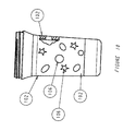
- a no spill cup with a soft gripping area can be provided, as shown in Figure 10.
- a soft ring 102 is provided around the outside of the cup. This ring can be of any width desired, and serves as a finger grip, to make it easier to grasp the cup securely. Preferably, the ring is approximately two inches (2") wide.
- the soft ring 102 has shapes or designs 106 cut out of it, such as stars, ovals, or so forth.
- the hard cup in turn, has raised areas or protuberances corresponding to those shapes or designs. The soft ring fits snugly over these raised areas of the cup, each of the protruding hard shapes fitting into the cutouts of the soft ring, with the surface of the raised areas and the soft ring being flush when the ring is inserted onto the cup.
- the cup is constructed from polycarbonate. In an alternate embodiment, the cup is constructed from polypropylene. If desired, clear polypropylene can be utilized. Alternatively, any other suitable materials can be used for the components of the no-spill cup.
- the components of the cup are all made of durable materials, resistant to breakage, dishwasher safe, and preferably color fast.
- cup 7 includes a no-spill cap or cover 11, a valve holder or assembly 31 and tumbler cup 22.
- No-spill cap 11 includes a spout 14 for drinking liquid from the cup.
- the spout is sized to allow an individual to place his or her mouth over the spout to drink therefrom.
- the spout is sized for the mouth of a child, particularly for a child of a young age.
- No-spill cap 11 forms a cover for placement over tumbler cup 22. When attached to the cup 22, a secure seal is formed such that no liquid can emerge through the connection between the cap 11 and cup 22. In use, cap 11 is sufficiently secured to cup 22 such that shaking the cup assembly, dropping the cup on the floor, or other vigorous movement of the cup assembly, or application of sharp force thereto, is insufficient to separate the cap from the cup.
- no-spill cap 11 and tumbler cup 22 include mating male and female screw threads, such that the cap 11 is a screw-on cap which can be easily rotated onto the tumbler cup 22, as shown in Figure 2.
- a snap-on cap is used, as shown in Figure 1.
- a resilient ring portion of cap 11 securely fits over lip 10 of tumbler cup 22, as is well known in the art.
- a screw-on cap or a snap-on cap are shown as two preferred embodiments, alternatively, any other suitable mechanism to secure the cap to the tumbler cup can be utilized.
- Either the screw-on cap and/or the snap-on cap can be further provided with a gasket 110 between the tumbler cup and the cap, to further seal the connection between the cup and the cap.
- This gasket can be part of the tumbler cup 22 or the cap 11, or can be a separate element inserted between the cap and the cup.
- the gasket 110 is part of cap 11, as shown in Figures 11(a)-(c).
- the cap can be provided with a small annular inner lip, on the inside of the cap, which acts as a gasket.
- This lip as shown in Figures 12(a)-(c), wedges inside the cup when the cap is screwed or placed upon it. The lip acts to further prevent the possibility of liquid flow through the contact between the cup and the cap.
- finger grips are provided on the outside of the cap, such as grooves or the like. These grips facilitate removal and application of the cap, particularly in embodiments requiring the screwing of the cap on and off of the cup.
- the cap is also preferably interchangeable with numerous tumbler cups of different sizes.
- the rim of the tumbler cups are all of the same diameter, although the tumbler cups themselves are of different volumes.
- the same sized cap could be used on a 6 1 ⁇ 2 oz. cup and/or a 7 oz. cup and/or a 9 oz. cup, and so forth.
- the cap has a soft spout 130 as shown in Figure 13.
- the spout is made of a thermo-elastimer.
- Spout 130 can be insert molded to a polypropylene cap, providing a combination cap having a hard section for attachment to the cup, and a soft spout portion.
- the spout has a small channel extending therethrough to reduce the liquid volume which can be trapped within the spout portion.
- the cap has a reduced volume spout as shown in Figure 14.
- Reduced volume spout 140 is designed to reduce the volume of liquid which can be trapped within the spout.
- Reduced volume spout 140 has a volume reduction member 144 inserted therein to reduce the internal volume of the spout, and to provide a channel 148 for liquid flow.
- valve assembly subunit 142 extends up into spout 140 to further reduce the amount of liquid which can be trapped in spout 140.
- Valve assembly subunit 142 can, for example, extend into volume reduction member 144. Accordingly, this embodiment reduces the space between the valve and the opening of the drinking spout, to reduce the amount of liquid potentially trapped in this area.
- valve assembly carriers 16 and 18 are tapered holes provided on the underside of the cap.
- Valve assembly carrier or tapered hole 18 leads to an open spout 14, providing a path for liquid flow.
- valve assembly carrier or hole 18 is fully open on both sides, both on its top surface, which leads to spout 14, and on its bottom surface opposite tumbler cup 32, for the flow of liquid out of tumbler cup 22 through hole 18 and through spout 14 into the user's mouth.
- Valve assembly carrier or tapered hole 16 in contrast, provides a passage for the flow of air into the cup during use, allowing liquid to exit through opposing hole 18 and spout 14.
- Hole 16 is open on one side, i.e. on its lower surface opposite tumbler cup 22. On the opposing side, hole 16 merges into the inner surface of cap 11.
- the inner surface of cap 11 is further provided with one or more, preferably small, vents or holes for air flow, allowing air to flow through the vents of cap 11 and through hole 16 into the cup assembly during use.
- no-spill cup 7 further includes valve holder or assembly 31.
- Valve holder 31 is preferably constructed from a high temperature ABS material, and is dimensioned to fit snugly into cap 11.
- valve holder is a separate assembly which fits into cap 11.
- the valve holder can be provided as an integral part of cap 11 and/or cup 7.
- valve holder 31 can be molded as a part of cap 11, such that the valve holder is inseparable from the cap.
- valve holder 31 is a two-subunit assembly connected by bridge 34. Each subunit of the two-subunit assembly is sized to frictionally fit into and be held by either one of tapered holes 16 and 18.
- the spacing between tapered holes 16 and 18 is the same as between the subunits of valve holder 31, such that the valve holder can be easily secured within cap 11.
- the sizing and tapering of holes 16 and 18 and the sizing of valve holder 31 are dimensioned so as to provide a secure, snug mating between the valve assembly and the tapered holes.
- the top of the valve holder (i.e. the side facing the spout) and the bottom of the valve holder (i.e. the side facing the cup) has two different diameters.
- the top is proportioned to fit snugly into the tapered hole, and the bottom is proportioned such that it cannot be inserted into hole 16 or 18. In this way, a mechanism is provided to prevent the valve holder from being inserted into the holes in the wrong orientation, i.e. upside down.
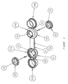
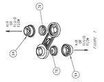
- FIG. 3 is an enlarged, exploded, perspective view of the valve holder of the present invention.
- Valve holder 31 consists of two valve holder subunits 37 and 39, connected by a bridge 34. Each valve holder subunit is intended to hold a single valve therein.
- valve or valve member 42 is intended for placement in subunit 37
- valve or valve member 45 is intended for placement in subunit 39.
- Valves 42 and 45 each include a slit for the passage of liquid. The slit is preferably through the center portion of the valve, and is dimensioned to allow a predetermined flow level or rate of liquid therethrough, as desired.
- Valve holder subunits 37 and 39 open into sealing units 37a and 39(a) and valve retainers or endcaps 37b and 39(b), respectively.
- subunit 37 is initially in an open position in which the sealing unit and the valve retainer have been pulled or hinged apart.
- the sealing unit and the valve retainer have a tab 60 connecting them, to prevent the components from being permanently separated accidentally.
- the valve retainer can be welded into place (e.g. by sonic welding), as shown in Figures 4 and 7.
- the sealing units each have at least one open section 58, such that, in the valve assembly's disassembled state, fluid can pass, unobstructed, through the sealing unit since no valve is in place.
- the valve retainers are open on both sides for unobstructed passage of fluid through the valve retainer in the disassembled state when no valve is in place.
- valve 42 is inserted into the valve holder by placement of the valve between sealing unit 37a and valve retainer 37b.
- the valve retainers can each be folded or hinged back about tab 60, over the sealing unit 37 (or under sealing unit 39, in the orientation shown in the figure) and snapped into place to close the subunits, as shown in Figure 5.
- the resilience of the sealing unit allows for a tight seal to be established between the valve retainer and the sealing unit.
- each subunit secures or encapsulates a valve tightly therein, maintaining the valve in place in the valve holder.
- subunit 37 is the subunit intended for initial placement into hole 18.
- valve 42 upon closing a subunit (e.g. subunit 37 in Figure 3), valve 42 sits securely against center seal-off stop or center stop 52 in sealing unit 37a, with the opening 70 in valve 42 being flush against center seal-off stop 52.
- Valve 42 includes a top, proximal side which will face the spout of the cap, and a distal side which rests against the center seal-off stop when the valve is placed in valve holder 31.
- Center stop 52 functions as a sealing portion or blocking element of the valve assembly which seals off and blocks the flow of fluid through the valve.
- center stop 52 consists of a solid central area or portion 56 which is impenetrable to the flow of liquid therethrough.
- Surrounding the central area or portion 56 is preferably a peripheral area or region 58, having open areas such as slots or so forth, for allowing the passage of liquid therethrough, as shown, for example in Figure 8(a).
- Central area 56 or center stop 52 further includes stems 74. As shown in Figure 9, stems 74 can further be reinforced with braces 72, which are reinforcing elements, which provide additional material strength to the connection between the stems and the valve holder.
- valve 42 When in the normal resting position, valve 42 relaxes to sit securely against the center stop 52, as shown in Figure 8(d). In this resting position, opening or orifice 70 of valve 42 presses firmly against the central area 56 of center stop 52, preventing any fluid flow through the valve, and maintaining the valve in a closed configuration.
- Valve 42 is constructed of a flexible material which is designed to fully invert and turn inside out, or to begin to invert and turn inside out, upon creation of a partial vacuum against the top of the valve 42, as shown in Figure 8(e).
- valve 42 can be a membrane, either in whole or in part.
- the valve is constructed of Kraton or silicone. If silicone is used, a 45 durometer silicone such as Lims 6045 is preferred, which is available from General Electric or from Wacker (a subsidiary of Bayer) of Germany.
- the materials used for the valve assembly and its components are sufficiently durable and heat resistant that the entire valve assembly can be placed in a dishwasher or boiled.
- the valve material is constructed of a single material with a greater thickness of material on the center area which seals off on the center stop, and with a thinner portion of material on the sidewalls. Providing a thinner sidewall portion contributes to the flexibility of the valve at its edges, which further assists and encourages inversion of the valve, by causing the valve to flex at the sidewalls first upon application of negative pressure thereto.
- Preferred dimensions for the valve thickness are approximately 0.4 mm of thickness on the sidewalls and approximately 0.9 mm of thickness on the center area.
- opening or orifice 70 is displaced away from central area 56 of center stop 52.
- the inversion of the valve therefore unblocks opening 70 allowing fluid flow through the subunit.
- negative pressure is being applied to the top of the valve 42 located next to the spout, negative pressure is likewise being applied to the bottom of the adjacent valve in the other subunit, located in the other tapered hole of the cup cover.
- this negative pressure opens the second valve as well, by displacing the opening in the other valve away from its center stop. Inversion of valves 42 allows fluid flow to proceed through both subunits of the assembly.
- Liquid will flow through one subunit of the valve assembly, the subunit connected to the spout, concurrently accompanied by air flow through the other subunit of the assembly, the subunit connected to the air vents. In this manner, liquid smoothly and easily flows though the valve assembly, the spout, and out of the cup.
- valve assembly is further provided with a flow bridge 84.
- Flow bridge 84 blocks movement or expansion of the valve 42 beyond a certain maximum distance to prevent the valve from overextending itself, or from being subjected to excessive strain or distension, as shown in Figure 8(e).
- the flow bridge prevents the valve from inverting beyond the point where it can no longer easily revert to its original position.
- the flow bridge provides a shield or a barrier preventing the valve from damage. Thus, it blocks objects such as a spoon or so forth, whether in a dishwasher or otherwise, from easily damaging the valve.
- valve When negative pressure is released or removed from the spout, the valve reverts back to its resting position, and fluid cannot flow through the closed slit in the valve. In the resting position, no liquid will spill from or emerge out of the cup.
- valve retainer 81 can alternatively be provided.
- valve retainer 94 can be provided as well.
- Valve retainers 81 and 94 serve the same function as valve retainers 37b and 39(b), holding and securing the valve within the valve assembly. It is preferred that the valve retainer, whichever embodiment is utilized, be sonic welded on, to ensure that the valve cannot be dislodged or removed from the holder.
- a system for maintaining a tight seal against fluid flow when the cup is not in use.
- An extremely secure seal is provided, such that excessive or vigorous shaking is ineffective to force fluid out of the cup.
- the valve construction disclosed results in a much tighter seal than that observed in the no-spill cup assemblies of the prior art. In accordance with the invention, unless the user sucks through the spout, no liquid will flow through the valve.
- subunits 37 and 39 are preferably identical in all respects excepts for the size of the orifice or slit in valve 42 and the slit in valve 45. It is preferred that one valve be provided with a larger opening than the other valve, such as a longer slit in one valve than the other. In one embodiment, one valve is provided with an opening in the form of a slit of approximately two hundred thousandths (200/1000) of an inch in length, while the second valve is provided with a slit of approximately fifty thousandths (50/1000) of an inch. Alternatively, other lengths may, of course, be used as well in accordance with the invention.
- the present inventor has further provided a novel dual acting flow system for regulating fluid flow.
- this system the level of flow of liquid out of the cup during use can be easily regulated. Regulation is accomplished by a simple rotation of the valve assembly which converts the cup between a faster or higher liquid flow, and a slower or lower flow system.
- valve holder 31 can be inserted into cap 11 in either of two configurations.
- valve 45 having a larger opening or slit
- a first, higher, flow level of liquid through the valve is established when the user sucks liquid through the spout, due to the use of the valve having the larger opening therein.
- the other valve 42 having the smaller opening, can be inserted into hole 18.
- This valve 42 provides a second, lower flow state, in which liquid can still flow out of the spout, but at a lower flow rate than flow through the first valve.
- the rate of flow of liquid out of the cup can be regulated by a parent.
- greater or fewer flow levels can be provided by varying the number of attached subunits having valves therein, or by providing replacement valve holders having different sized openings 70 therein. In all configurations, however, liquid only flows through the valve when the user sucks through the spout, as disclosed above.
- the opening 70 can be, for example, a slit, a slot, an orifice, a hole, or so forth. Likewise, by the term opening, it is contemplated that multiple openings of these or any other types can be provided as well.
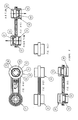
- the opening 70 is an "X" shaped slot 78, as shown in Figure 7.
- the opening is a "T" shaped slot 76, as also shown in Figure 7.
- Use of the X-shaped slot 78 shown in Figure 7, will provide a higher flow rate than the T-shaped slot 76 shown therein.
- the flow rate depends on the total length of the slots, or in general, on the size of the opening. Accordingly, both the X-shaped slot and the T-shaped slot can be used in a single valve assembly, each placed in its respective subunit. In this preferred embodiment, a two level flow system is provided, as previously discussed.
- both openings are X-shaped, with one opening larger than the other.
- a 7mm opening (the length from end to end of each crossbar of the "X") can be used for the fast side, and a 6mm opening for the slow side.
- valve holder be marked to indicate which subunit is suitable for higher flow, and which for lower flow of liquid therethrough.
- the valve holders can be explicitly marked “Fast” and “Slow” as shown in Figures 7 and 9, respectively.
- the subunits or the valve holders can be marked with a hare or rabbit, signifying fast flow, and a tortoise or turtle, signifying slow flow, as respectively also shown in Figures 7 and 9.
- the subunit connected to the spout is, of course, the subunit which controls the liquid flow rate.
- the valve holder can be marked, for example, on the subunit itself, or on the bridge in an area directly adjacent to the subunit, as shown in the figures.
- the valve holder is marked on the top and bottom (i.e. the sides facing the spout and the cup, respectively), such that the symbols and/or words can be seen from the top when the valve holder is being inserted, and from the bottom, once it has already been inserted, to determine which speed valve is in place in the spout.
- the words and/or symbols are only on the bottom of the valve, so that the user can see them from the bottom when inserting the valve holder, and can also view the valve holder from the bottom, once inserted.
Abstract
Description
- The present application claims all rights of priority to
U.S. Provisional Patent Application No. 60,056,218, filed August 21, 1997 - The present invention relates to a no-spill cup assembly with an improved valve mechanism to prevent liquid from flowing out of the cup when not desired.
- No-spill cup assemblies are well known in the art. In the past, a variety of such assemblies have been developed and marketed. In general, the goal of a no-spill cup is to provide a construction which minimizes or prevents liquid from emerging out of the cup when liquid flow is not desired, i.e. when the user is not drinking. However, though the assemblies of the prior art are intended to avoid such accidents, their construction is such that they generally do not provide a secure enough protection against undesirable spilling or leakage. Thus, when such cups are inverted, or more significantly, when they are shaken vigorously, liquid will often emerge from them. This can be a particular problem with young children, for whom these cups are usually intended. Accordingly, there is a need in the art for an improved cup assembly for preventing undesired spilling of liquids.
- It is an object of the present invention to provide an improved no-spill cup assembly.
- It is a further object of the present invention to provide a cup assembly which prevents liquid from flowing out of the cup when the user is not drinking.
- It is a further object of the invention to provide a cup assembly which minimizes and/or eliminates accidental or undesirable liquid flow or spillage out of the cup.
- It is a further object of the invention to provide a cup assembly which provides the ability to regulate the flow rate of liquid out of the cup.
- It is a further object of the invention to provide a cup assembly which can be used by young children, to avoid accidental spilling of liquid therefrom.
- Further objects of the invention will become apparent in conjunction with the disclosure herein.
- In accordance with the invention, an improved cup construction and valve assembly is provided which provides an extremely secure seal against accidental liquid flow from the cup spout. Further to the invention, a user places his or her mouth against the spout of the cup assembly to suck liquid out of the cup when desired. The act of sucking at the spout of the cup creates negative pressure or a partial vacuum against a valve in the cup spout, causing the valve to invert, or turn inside out, either partially or totally, thereby unblocking an opening such as an orifice or slit in the valve. Once the opening is unblocked, liquid can flow freely through the valve and spout.
- In contrast, when not in use, the valve sits in a resting, closed position, with the valve pressed against the center seal-off, thereby sealing off the opening or slit in the valve assembly. Thus, in its relaxed state, with no negative pressure applied, the valve sits in a closed position with the fluid opening sealed by the center seal-off. Moreover, in accordance with the dual valve nature of the device in the preferred embodiment, an adjacent valve similarly seals when no negative pressure is applied, thereby blocking off the air vents in the cover of the cup, and further preventing the possibility of fluid flow. Consequently, the closed position provides an extremely secure seal against fluid leakage, such that inadvertent spills or even deliberate attempts to force liquid outside of the cup, such as by turning the cup upside down, or shaking the cup, are ineffective.
- In a further embodiment of the invention, the cup assembly allows liquid flow to be regulated between regular or maximum flow and minimal flow levels or rates by rotating the position of a valve assembly in the cap or cover of the cup. The valve holder is constructed as a two subunit assembly, with one subassembly holding a valve with a larger slit or orifice for fluid flow than the valve in the second subunit. Thus, upon rotation of the valve holder, either a low-flow valve or a higher flow valve can be positioned in the hole leading to the spout. In this manner, a dual position valve assembly is provided allowing either regular flow or minimal liquid flow conditions.
-
- Figure 1(a) is an exploded front view of a no-spill cup assembly in accordance with the present invention. Figure 1(b) is an exploded perspective view of the no-spill cup assembly of Figure 1(a).
- Figure 2(a) is an exploded front view of a second embodiment of a no-spill cup assembly in accordance with the present invention. Figure 1(b) is an exploded perspective view of the no-spill cup assembly of Figure 2(a).
- Figure 3 is a perspective view of the valve assembly of the present invention.
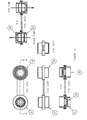
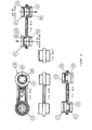
- Figure 4 is an exploded, perspective view of another embodiment of the valve assembly of the no-spill cup, in accordance with the present invention.
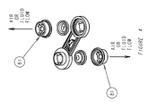
- Figure 5(a) is an exploded front view of the cup assembly of the present invention, showing the rotation of the valve holder or assembly, into two alternate positions for placement in the cap or cover of the cup. Figure 5(b) is an exploded perspective view, showing the placement of the valve holder into the cap, in either of the two positions illustrated in Figure 5(a).
- Figure 6 is a series of additional views of the valve holder or assembly of Figure 3. Figure 6(a) is a top view of the valve holder. Figure 6(b) is a front view of the valve holder. Figure 6(c) is a side view of the valve holder. Figure 6(d) is a cross-sectional view of the valve holder wherein the valve is in a relaxed state, sealing off fluid flow. Figure 6(e) is a cross-sectional view of the valve holder, showing the valve in an inverted state, to allow fluid flow through the valve.
- Figure 7 is an exploded, perspective view of another embodiment of the valve assembly of the no-spill cup, in accordance with the present invention.
- Figure 8 is a series of additional views of a further embodiment of the valve assembly shown in Figure 6. Figure 8(a) is a top view of the valve holder or assembly. Figure 8(b) is a front view of the valve holder. Figure 8(c) is a side view of the valve holder. Figure 8(d) is a cross-sectional view of the valve holder wherein the valve is in a relaxed state, sealing off fluid flow. Figure 8(e) is a cross-sectional view of the valve holder, showing the valve in an inverted state, to allow fluid flow through the valve.
- Figure 9 is a series of additional views of another embodiment of the valve assembly shown in Figure 8. Figure 9(a) is a top view of the valve holder or assembly. Figure 9(b) is a front view of the valve holder. Figure 9(c) is a side view of the valve holder. Figure 9(d) is a cross-sectional view of the valve holder wherein the valve is in a relaxed state, sealing off fluid flow. Figure 9(e) is a cross-sectional view of the valve holder, showing the valve in an inverted state, to allow fluid flow through the valve.
- Figure 10 is a side view of a no-spill cup with a soft gripping area, in accordance with the present invention.
- Figure 11 is a series of additional views of another embodiment of the cap of the present invention. Figure 11(a) is a partial sectional view of a cap with an insert molded or glued in gasket, in accordance with the invention. Figure 11(b) is a side sectional view of the cap of Figure 11(a). Figure 11(c) is a top sectional view of the cap of Figure 11(b).
- Figure 12 is a series of additional views of another embodiment of the cap of the present invention. Figure 12(a) is a partial sectional view of a cap with a molded lip which wedges against into the inside surface of the cup, in accordance with the invention. Figure 12(b) is a side sectional view of the cap of Figure 12(a). Figure 12(c) is a top sectional view of the cap of Figure 12(b).
- Figure 13 is a side sectional view of a cap having a soft spout, in accordance with a further embodiment of the invention.
- Figure 14 is a side sectional view of a cap having a reduced volume spout, in accordance with a further embodiment of the invention.
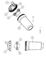
- As will be shown in conjunction with the attached drawings, a novel cup assembly is disclosed for providing prevention against accidental liquid spills. Figures 1(a) and 1(b) are a front view and a perspective view, respectively, of an embodiment of the cup assembly, in accordance with the present invention. The volume of the cup or liquid holding portion of the assembly can be adjusted as desired. In one embodiment, a 7 oz. drinking cup is provided, as shown in Figure 1. Alternatively, a 9 oz. drinking cup, as shown in Figure 2, a 6 ½ oz. cup, or any other desired size can be provided, as well.
- The sides of the cup can be provided with no handles, one handle, two handles or any other number of handles, for the user's use to grip the cup. This handle or handle is preferably sized for a child's hands. In addition, the outside appearance of the cup and/or the cap can be a solid color, or can be printed with any desired design.
- In a further embodiment of the invention, a no spill cup with a soft gripping area can be provided, as shown in Figure 10. In accordance with this embodiment, a
soft ring 102 is provided around the outside of the cup. This ring can be of any width desired, and serves as a finger grip, to make it easier to grasp the cup securely. Preferably, the ring is approximately two inches (2") wide. In a preferred embodiment, thesoft ring 102 has shapes ordesigns 106 cut out of it, such as stars, ovals, or so forth. The hard cup, in turn, has raised areas or protuberances corresponding to those shapes or designs. The soft ring fits snugly over these raised areas of the cup, each of the protruding hard shapes fitting into the cutouts of the soft ring, with the surface of the raised areas and the soft ring being flush when the ring is inserted onto the cup. - In one embodiment of the invention, the cup is constructed from polycarbonate. In an alternate embodiment, the cup is constructed from polypropylene. If desired, clear polypropylene can be utilized. Alternatively, any other suitable materials can be used for the components of the no-spill cup. The components of the cup are all made of durable materials, resistant to breakage, dishwasher safe, and preferably color fast.
- In accordance with the invention,
cup 7 includes a no-spill cap or cover 11, a valve holder orassembly 31 andtumbler cup 22. No-spill cap 11 includes aspout 14 for drinking liquid from the cup. The spout is sized to allow an individual to place his or her mouth over the spout to drink therefrom. In the preferred embodiment, the spout is sized for the mouth of a child, particularly for a child of a young age. - No-spill cap 11 forms a cover for placement over
tumbler cup 22. When attached to thecup 22, a secure seal is formed such that no liquid can emerge through the connection between the cap 11 andcup 22. In use, cap 11 is sufficiently secured tocup 22 such that shaking the cup assembly, dropping the cup on the floor, or other vigorous movement of the cup assembly, or application of sharp force thereto, is insufficient to separate the cap from the cup. - In one embodiment, no-spill cap 11 and
tumbler cup 22 include mating male and female screw threads, such that the cap 11 is a screw-on cap which can be easily rotated onto thetumbler cup 22, as shown in Figure 2. In an alternative embodiment, a snap-on cap is used, as shown in Figure 1. In this embodiment, a resilient ring portion of cap 11 securely fits overlip 10 oftumbler cup 22, as is well known in the art. Although a screw-on cap or a snap-on cap are shown as two preferred embodiments, alternatively, any other suitable mechanism to secure the cap to the tumbler cup can be utilized. - Either the screw-on cap and/or the snap-on cap can be further provided with a
gasket 110 between the tumbler cup and the cap, to further seal the connection between the cup and the cap. This gasket can be part of thetumbler cup 22 or the cap 11, or can be a separate element inserted between the cap and the cup. In a preferred embodiment, thegasket 110 is part of cap 11, as shown in Figures 11(a)-(c). - Alternatively, the cap can be provided with a small annular inner lip, on the inside of the cap, which acts as a gasket. This lip, as shown in Figures 12(a)-(c), wedges inside the cup when the cap is screwed or placed upon it. The lip acts to further prevent the possibility of liquid flow through the contact between the cup and the cap.
- In a preferred embodiment, finger grips are provided on the outside of the cap, such as grooves or the like. These grips facilitate removal and application of the cap, particularly in embodiments requiring the screwing of the cap on and off of the cup.
- The cap is also preferably interchangeable with numerous tumbler cups of different sizes. In this embodiment, the rim of the tumbler cups are all of the same diameter, although the tumbler cups themselves are of different volumes. For example, the same sized cap could be used on a 6 ½ oz. cup and/or a 7 oz. cup and/or a 9 oz. cup, and so forth.
- In a further embodiment of the cap, the cap has a
soft spout 130 as shown in Figure 13. Preferably, the spout is made of a thermo-elastimer. Spout 130 can be insert molded to a polypropylene cap, providing a combination cap having a hard section for attachment to the cup, and a soft spout portion. Preferably, the spout has a small channel extending therethrough to reduce the liquid volume which can be trapped within the spout portion. - In a further embodiment of the cap, the cap has a reduced volume spout as shown in Figure 14. Reduced
volume spout 140 is designed to reduce the volume of liquid which can be trapped within the spout. Reducedvolume spout 140 has avolume reduction member 144 inserted therein to reduce the internal volume of the spout, and to provide achannel 148 for liquid flow. Preferably,valve assembly subunit 142 extends up intospout 140 to further reduce the amount of liquid which can be trapped inspout 140.Valve assembly subunit 142 can, for example, extend intovolume reduction member 144. Accordingly, this embodiment reduces the space between the valve and the opening of the drinking spout, to reduce the amount of liquid potentially trapped in this area. - As shown in Figure 1(b), no-spill cap 11 includes
valve assembly carriers valve assembly carriers hole 18 leads to anopen spout 14, providing a path for liquid flow. Thus, valve assembly carrier orhole 18 is fully open on both sides, both on its top surface, which leads to spout 14, and on its bottom surface opposite tumbler cup 32, for the flow of liquid out oftumbler cup 22 throughhole 18 and throughspout 14 into the user's mouth. - Valve assembly carrier or tapered
hole 16, in contrast, provides a passage for the flow of air into the cup during use, allowing liquid to exit through opposinghole 18 andspout 14.Hole 16 is open on one side, i.e. on its lower surface oppositetumbler cup 22. On the opposing side,hole 16 merges into the inner surface of cap 11. The inner surface of cap 11 is further provided with one or more, preferably small, vents or holes for air flow, allowing air to flow through the vents of cap 11 and throughhole 16 into the cup assembly during use. - As shown in Figures 1 and 2, no-
spill cup 7 further includes valve holder orassembly 31.Valve holder 31 is preferably constructed from a high temperature ABS material, and is dimensioned to fit snugly into cap 11. In the preferred embodiment, valve holder is a separate assembly which fits into cap 11. Alternatively, the valve holder can be provided as an integral part of cap 11 and/orcup 7. For example,valve holder 31 can be molded as a part of cap 11, such that the valve holder is inseparable from the cap. - In the preferred embodiment,
valve holder 31 is a two-subunit assembly connected bybridge 34. Each subunit of the two-subunit assembly is sized to frictionally fit into and be held by either one of taperedholes holes valve holder 31, such that the valve holder can be easily secured within cap 11. The sizing and tapering ofholes valve holder 31 are dimensioned so as to provide a secure, snug mating between the valve assembly and the tapered holes. In a preferred embodiment, the top of the valve holder (i.e. the side facing the spout) and the bottom of the valve holder (i.e. the side facing the cup) has two different diameters. The top is proportioned to fit snugly into the tapered hole, and the bottom is proportioned such that it cannot be inserted intohole - Figure 3 is an enlarged, exploded, perspective view of the valve holder of the present invention.
Valve holder 31 consists of twovalve holder subunits bridge 34. Each valve holder subunit is intended to hold a single valve therein. As shown in the figure, valve orvalve member 42 is intended for placement insubunit 37, and valve orvalve member 45 is intended for placement insubunit 39.Valves -
Valve holder subunits subunit 37 as an example of the function of each subunit, as shown in Figure 3,subunit 37 is initially in an open position in which the sealing unit and the valve retainer have been pulled or hinged apart. In one embodiment, the sealing unit and the valve retainer have atab 60 connecting them, to prevent the components from being permanently separated accidentally. Alternatively, the valve retainer can be welded into place (e.g. by sonic welding), as shown in Figures 4 and 7. The sealing units each have at least oneopen section 58, such that, in the valve assembly's disassembled state, fluid can pass, unobstructed, through the sealing unit since no valve is in place. Likewise, the valve retainers are open on both sides for unobstructed passage of fluid through the valve retainer in the disassembled state when no valve is in place. - To assemble the valve assembly,
valve 42 is inserted into the valve holder by placement of the valve between sealing unit 37a and valve retainer 37b. After a valve has been placed into one or both of the subunits, the valve retainers can each be folded or hinged back abouttab 60, over the sealing unit 37 (or under sealingunit 39, in the orientation shown in the figure) and snapped into place to close the subunits, as shown in Figure 5. The resilience of the sealing unit allows for a tight seal to be established between the valve retainer and the sealing unit. When closed, each subunit secures or encapsulates a valve tightly therein, maintaining the valve in place in the valve holder. For clarity, reference is primarily made to subunit 37, althoughsubunits subunit 37 is the subunit intended for initial placement intohole 18. - As shown in Figures 5, 6, 8 and 9, upon closing a subunit (
e.g. subunit 37 in Figure 3),valve 42 sits securely against center seal-off stop orcenter stop 52 in sealing unit 37a, with theopening 70 invalve 42 being flush against center seal-off stop 52.Valve 42 includes a top, proximal side which will face the spout of the cap, and a distal side which rests against the center seal-off stop when the valve is placed invalve holder 31. - Center stop 52 functions as a sealing portion or blocking element of the valve assembly which seals off and blocks the flow of fluid through the valve. In a preferred embodiment,
center stop 52 consists of a solid central area orportion 56 which is impenetrable to the flow of liquid therethrough. Surrounding the central area orportion 56 is preferably a peripheral area orregion 58, having open areas such as slots or so forth, for allowing the passage of liquid therethrough, as shown, for example in Figure 8(a).Central area 56 or center stop 52 further includes stems 74. As shown in Figure 9, stems 74 can further be reinforced withbraces 72, which are reinforcing elements, which provide additional material strength to the connection between the stems and the valve holder. - When in the normal resting position,
valve 42 relaxes to sit securely against thecenter stop 52, as shown in Figure 8(d). In this resting position, opening ororifice 70 ofvalve 42 presses firmly against thecentral area 56 ofcenter stop 52, preventing any fluid flow through the valve, and maintaining the valve in a closed configuration. - To drink from the cup, a user raises the cup to his or her mouth and begins to suck liquid through
spout 14. In the process, the user creates negative pressure or a partial vacuum against the top ofvalve 42 insubunit 37.Valve 42 is constructed of a flexible material which is designed to fully invert and turn inside out, or to begin to invert and turn inside out, upon creation of a partial vacuum against the top of thevalve 42, as shown in Figure 8(e). For example,valve 42 can be a membrane, either in whole or in part. Preferably, the valve is constructed of Kraton or silicone. If silicone is used, a 45 durometer silicone such as Lims 6045 is preferred, which is available from General Electric or from Wacker (a subsidiary of Bayer) of Germany. The materials used for the valve assembly and its components are sufficiently durable and heat resistant that the entire valve assembly can be placed in a dishwasher or boiled. - In a preferred embodiment, the valve material is constructed of a single material with a greater thickness of material on the center area which seals off on the center stop, and with a thinner portion of material on the sidewalls. Providing a thinner sidewall portion contributes to the flexibility of the valve at its edges, which further assists and encourages inversion of the valve, by causing the valve to flex at the sidewalls first upon application of negative pressure thereto. Preferred dimensions for the valve thickness are approximately 0.4 mm of thickness on the sidewalls and approximately 0.9 mm of thickness on the center area.
- Upon inversion of
valve 42, opening ororifice 70 is displaced away fromcentral area 56 ofcenter stop 52. The inversion of the valve therefore unblocks opening 70 allowing fluid flow through the subunit. As negative pressure is being applied to the top of thevalve 42 located next to the spout, negative pressure is likewise being applied to the bottom of the adjacent valve in the other subunit, located in the other tapered hole of the cup cover. Thus, this negative pressure, opens the second valve as well, by displacing the opening in the other valve away from its center stop. Inversion ofvalves 42 allows fluid flow to proceed through both subunits of the assembly. Liquid will flow through one subunit of the valve assembly, the subunit connected to the spout, concurrently accompanied by air flow through the other subunit of the assembly, the subunit connected to the air vents. In this manner, liquid smoothly and easily flows though the valve assembly, the spout, and out of the cup. - In a preferred embodiment, the valve assembly is further provided with a
flow bridge 84.Flow bridge 84 blocks movement or expansion of thevalve 42 beyond a certain maximum distance to prevent the valve from overextending itself, or from being subjected to excessive strain or distension, as shown in Figure 8(e). Thus, the flow bridge prevents the valve from inverting beyond the point where it can no longer easily revert to its original position. In addition, the flow bridge provides a shield or a barrier preventing the valve from damage. Thus, it blocks objects such as a spoon or so forth, whether in a dishwasher or otherwise, from easily damaging the valve. - When negative pressure is released or removed from the spout, the valve reverts back to its resting position, and fluid cannot flow through the closed slit in the valve. In the resting position, no liquid will spill from or emerge out of the cup.
- Further embodiments of the valve holder and assembly are shown in Figures 4 and 7-9. As shown in Figure 4, instead of the valve retainer shown in Figure 3, a detachable snap
fit valve retainer 81 can alternatively be provided. Or, as shown in Figure 7,valve retainer 94 can be provided as well.Valve retainers - Thus, in accordance with the invention, a system is provided for maintaining a tight seal against fluid flow when the cup is not in use. An extremely secure seal is provided, such that excessive or vigorous shaking is ineffective to force fluid out of the cup. Significantly, the valve construction disclosed results in a much tighter seal than that observed in the no-spill cup assemblies of the prior art. In accordance with the invention, unless the user sucks through the spout, no liquid will flow through the valve.
- In the preferred embodiment,
subunits valve 42 and the slit invalve 45. It is preferred that one valve be provided with a larger opening than the other valve, such as a longer slit in one valve than the other. In one embodiment, one valve is provided with an opening in the form of a slit of approximately two hundred thousandths (200/1000) of an inch in length, while the second valve is provided with a slit of approximately fifty thousandths (50/1000) of an inch. Alternatively, other lengths may, of course, be used as well in accordance with the invention. - By varying the size and/or shape of the opening in the valve, the present inventor has further provided a novel dual acting flow system for regulating fluid flow. In this system, the level of flow of liquid out of the cup during use can be easily regulated. Regulation is accomplished by a simple rotation of the valve assembly which converts the cup between a faster or higher liquid flow, and a slower or lower flow system.
- As shown in Figure 5,
valve holder 31 can be inserted into cap 11 in either of two configurations. In a first configuration,valve 45, having a larger opening or slit, is placed intohole 18, the hole in communication withspout 14. In this configuration, a first, higher, flow level of liquid through the valve is established when the user sucks liquid through the spout, due to the use of the valve having the larger opening therein. By removing thevalve holder 31 fromholes valve holder 31 one hundred eighty degrees (180°), theother valve 42, having the smaller opening, can be inserted intohole 18. Thisvalve 42 provides a second, lower flow state, in which liquid can still flow out of the spout, but at a lower flow rate than flow through the first valve. In this way, the rate of flow of liquid out of the cup can be regulated by a parent. Although a two level flow system is disclosed, greater or fewer flow levels can be provided by varying the number of attached subunits having valves therein, or by providing replacement valve holders having differentsized openings 70 therein. In all configurations, however, liquid only flows through the valve when the user sucks through the spout, as disclosed above. - Any form of desired opening suitable for passage of a desired level of liquid can be utilized in the valve. The
opening 70 can be, for example, a slit, a slot, an orifice, a hole, or so forth. Likewise, by the term opening, it is contemplated that multiple openings of these or any other types can be provided as well. - In one embodiment, the
opening 70 is an "X" shapedslot 78, as shown in Figure 7. In another preferred embodiment, the opening is a "T" shapedslot 76, as also shown in Figure 7. Use of theX-shaped slot 78 shown in Figure 7, will provide a higher flow rate than the T-shapedslot 76 shown therein. The flow rate, of course, depends on the total length of the slots, or in general, on the size of the opening. Accordingly, both the X-shaped slot and the T-shaped slot can be used in a single valve assembly, each placed in its respective subunit. In this preferred embodiment, a two level flow system is provided, as previously discussed. - In a further embodiment, both openings are X-shaped, with one opening larger than the other. A 7mm opening (the length from end to end of each crossbar of the "X") can be used for the fast side, and a 6mm opening for the slow side.
- It is further preferred that the valve holder be marked to indicate which subunit is suitable for higher flow, and which for lower flow of liquid therethrough. Accordingly, the valve holders can be explicitly marked "Fast" and "Slow" as shown in Figures 7 and 9, respectively. Alternatively, or additionally, the subunits or the valve holders can be marked with a hare or rabbit, signifying fast flow, and a tortoise or turtle, signifying slow flow, as respectively also shown in Figures 7 and 9. The subunit connected to the spout is, of course, the subunit which controls the liquid flow rate. The valve holder can be marked, for example, on the subunit itself, or on the bridge in an area directly adjacent to the subunit, as shown in the figures. In one embodiment, the valve holder is marked on the top and bottom (i.e. the sides facing the spout and the cup, respectively), such that the symbols and/or words can be seen from the top when the valve holder is being inserted, and from the bottom, once it has already been inserted, to determine which speed valve is in place in the spout. In an alternate embodiment, the words and/or symbols are only on the bottom of the valve, so that the user can see them from the bottom when inserting the valve holder, and can also view the valve holder from the bottom, once inserted.
- Having described this invention with regard to specific embodiments, it is to be understood that the description is not meant as a limitation since further modifications may suggest themselves, or may be apparent to those in the art. It is intended that the present application cover all such modifications and improvements thereon.
Claims (30)
- An apparatus for use in a no-spill drinking cup, said apparatus comprising:a valve holder, such valve holder comprising at least one valve, said valve having a resting position and being closed to block the passage of liquid therethrough while in said resting position, said valve being movable into an open position for the passage of liquid therethrough upon the application of negative pressure to the top of said valve.
- An apparatus for use in a no-spill drinking cup, comprising:a flexible valve member, said valve member having a closed position andan open position, wherein said valve member sits against a sealing portion when in said closed position such that said sealing portion blocks the passage of fluid through said valve member, and wherein said valve member moves away from said sealing portion to allow passage of liquid though said valve member upon application of negative pressure to said valve member.
- An apparatus for use in a no-spill cup, comprising:a flexible valve member comprising an opening in said valve member, said flexible member having a proximal side and a distal side; anda sealing portion, said sealing portion comprising a first area which is impenetrable to the flow of liquid therethrough, and a second area through which liquid can flow, said distal side of said flexible valve member resting against said sealing portion when said flexible valve member is in the resting, closed position such that said opening of said flexible valve member rests against said first area when said flexible valve member is in said resting, closed position, said flexible valve member backing off said sealing portion upon the application of negative pressure to said proximal side of said flexible valve member to allow fluid to flow through said second area of said sealing portion and through said opening of said flexible valve member.
- An apparatus as claimed in Claim 3, wherein said first area is the central area of said sealing portion, and wherein said second area is the peripheral area of said sealing portion.
- A no-spill drinking cup assembly, comprising:a flexible valve member, said flexible valve member having an opening therein; and,a sealing portion, said flexible valve member resting against said sealing portion when said valve member is in its closed position such that said opening sits against said sealing portion to block the passage of liquid through said opening.
- An assembly as claimed in Claim 5, said flexible valve member further comprising an open position, said flexible valve member being displaced away from said sealing portion in said open position to provide liquid access to said opening, said flexible member assuming said open position upon application of negative pressure to the top of said valve member.
- An assembly as claimed in Claim 6, wherein said flexible valve member inverts upon application of negative pressure to said valve member to move said opening away from said sealing portion.
- An assembly as claimed in Claim 5, wherein said flexible valve member is located in a valve assembly.
- An assembly as claimed in Claim 8, wherein said valve assembly comprises at least one subunit for containing said valve member.
- An assembly as claimed in Claim 9, wherein said valve assembly comprises at least two subunits, each of said subunits comprising a valve member therein.
- An assembly as claimed in Claim 9. wherein said valve assembly comprises at least two subunits, a first subunit comprising a first valve member comprising a first opening, and a second subunit comprising a second valve member comprising a second opening, said first opening being larger than said second opening.
- An assembly as claimed in Claim 11, wherein said first opening is an "X" shaped slot.
- An assembly as claimed in Claim 11, wherein said second opening is a "T" shaped slot.
- An assembly as claimed in Claim 11, wherein said first opening is an "X" shaped slot and said second opening is a "T" shaped slot.
- An assembly as claimed in Claim 5, wherein said assembly further comprises a removable cap.
- An assembly as claimed in Claim 5, wherein said cap comprises a valve assembly carrier for securing said valve assembly to said cap.
- An assembly as claimed in Claim 15, further comprising a cup for attachment to said removable cap.
- An assembly as claimed in Claim 17, wherein said cap is provided with screw threads for screwing onto said cup.
- An assembly as claimed in Claim 17, wherein said cap is a snap-on cap, for attachment to said cup.
- An assembly as claimed in Claim 9, wherein said sealing portion is located in said subunit.
- An assembly as claimed in Claim 20, wherein said sealing portion comprises a center seal-off stop, said center seal-off stop comprising a solid central area impenetrable to liquid flow therethrough, and a peripheral region surrounding said central area, said peripheral region having at least one area open to the passage of liquid therethrough.
- An assembly as claimed in Claim 21, wherein said opening rests against said central region when said valve member is in its closed position.
- An assembly as claimed in Claim 20, wherein said subunit comprises a valve retainer for securing said flexible valve member in said subunit.
- An apparatus for use with a no-spill drinking cup, comprising:a cap for attachment to a cup, said cap comprising a spout;a valve assembly, at least a portion of said valve assembly being in communication with said spout, said valve assembly comprising at least one flexible valve member having an opening therein, said flexible valve member resting in a closed position in which no liquid can pass through said opening of said valve, said valve moving to an open position to allow the passage of liquid through said valve when negative pressure is applied to said valve through said spout.
- An apparatus as claimed in Claim 24, wherein said valve assembly further comprises a sealing portion, said sealing portion comprising a first area and a second area, wherein said first area is impenetrable to liquid flow therethrough, and said second area allows the passage of liquid through said second area.
- An apparatus as claimed in Claim 25, wherein said first area is the central area of said sealing portion and said second area is the peripheral area of said sealing portion.
- An apparatus as claimed in Claim 24, wherein said cap further comprises at least one vent in the surface of said cap to allow the passage of air through said vent.
- An apparatus as claimed in Claim 24, wherein said valve assembly comprises at least two subunits, said two subunits comprising a first subunit and a second subunit, said first subunit being in communication with said spout, said second subunit being in communication with said vent in said cap.
- An apparatus as claimed in Claim 23, further comprising a cup.
- An apparatus as claimed in Claim 24, wherein said cup is attached to said cap.
Applications Claiming Priority (2)
| Application Number | Priority Date | Filing Date | Title |
|---|---|---|---|
| US5621897P | 1997-08-21 | 1997-08-21 | |
| EP98943302A EP1014839B1 (en) | 1997-08-21 | 1998-08-21 | No-spill drinking cup apparatus |
Related Parent Applications (1)
| Application Number | Title | Priority Date | Filing Date |
|---|---|---|---|
| EP98943302A Division EP1014839B1 (en) | 1997-08-21 | 1998-08-21 | No-spill drinking cup apparatus |
Publications (2)
| Publication Number | Publication Date |
|---|---|
| EP1880645A2 true EP1880645A2 (en) | 2008-01-23 |
| EP1880645A3 EP1880645A3 (en) | 2008-01-30 |
Family
ID=38872002
Family Applications (1)
| Application Number | Title | Priority Date | Filing Date |
|---|---|---|---|
| EP07015953A Withdrawn EP1880645A3 (en) | 1997-08-21 | 1998-08-21 | No-spill drinking cup apparatus |
Country Status (1)
| Country | Link |
|---|---|
| EP (1) | EP1880645A3 (en) |
Citations (10)
| Publication number | Priority date | Publication date | Assignee | Title |
|---|---|---|---|---|
| FR1191181A (en) | 1957-04-17 | 1959-10-16 | Self-regulating valve particularly applicable to artificial and mixed breastfeeding | |
| EP0388828A1 (en) | 1989-03-23 | 1990-09-26 | Ica S.P.A. | Single-acting valve for fluids |
| GB2258860A (en) | 1991-08-07 | 1993-02-24 | Polytop Plastics | Valved closure |
| US5250266A (en) | 1990-11-30 | 1993-10-05 | Ciba Vision Corporation | Contact lens case venting system |
| US5439143A (en) | 1991-12-06 | 1995-08-08 | Liquid Molding Systems, Inc. | Dispensing valve for packaging |
| US5542670A (en) | 1995-07-17 | 1996-08-06 | Playtex Products, Inc. | Flow control element and covered drinking cup |
| US5607073A (en) | 1996-02-20 | 1997-03-04 | Forrer; Scott M. | Valve |
| US5609582A (en) | 1995-04-14 | 1997-03-11 | Kruetten; Victor | Drinking aid device for elderly people, patients and the like |
| WO1998017157A1 (en) | 1996-10-21 | 1998-04-30 | Gerber Products Company | Cap for drinking cup having outlet valve |
| WO1999038423A1 (en) | 1998-01-30 | 1999-08-05 | Cannon Rubber Limited | Closure assembly for a drinking vessel |
Family Cites Families (1)
| Publication number | Priority date | Publication date | Assignee | Title |
|---|---|---|---|---|
| US5706973A (en) * | 1997-01-30 | 1998-01-13 | E. S. Robbins Corporation | Drinking cup and cover with flow control elements |
-
1998
- 1998-08-21 EP EP07015953A patent/EP1880645A3/en not_active Withdrawn
Patent Citations (10)
| Publication number | Priority date | Publication date | Assignee | Title |
|---|---|---|---|---|
| FR1191181A (en) | 1957-04-17 | 1959-10-16 | Self-regulating valve particularly applicable to artificial and mixed breastfeeding | |
| EP0388828A1 (en) | 1989-03-23 | 1990-09-26 | Ica S.P.A. | Single-acting valve for fluids |
| US5250266A (en) | 1990-11-30 | 1993-10-05 | Ciba Vision Corporation | Contact lens case venting system |
| GB2258860A (en) | 1991-08-07 | 1993-02-24 | Polytop Plastics | Valved closure |
| US5439143A (en) | 1991-12-06 | 1995-08-08 | Liquid Molding Systems, Inc. | Dispensing valve for packaging |
| US5609582A (en) | 1995-04-14 | 1997-03-11 | Kruetten; Victor | Drinking aid device for elderly people, patients and the like |
| US5542670A (en) | 1995-07-17 | 1996-08-06 | Playtex Products, Inc. | Flow control element and covered drinking cup |
| US5607073A (en) | 1996-02-20 | 1997-03-04 | Forrer; Scott M. | Valve |
| WO1998017157A1 (en) | 1996-10-21 | 1998-04-30 | Gerber Products Company | Cap for drinking cup having outlet valve |
| WO1999038423A1 (en) | 1998-01-30 | 1999-08-05 | Cannon Rubber Limited | Closure assembly for a drinking vessel |
Also Published As
| Publication number | Publication date |
|---|---|
| EP1880645A3 (en) | 2008-01-30 |
Similar Documents
| Publication | Publication Date | Title |
|---|---|---|
| US6321931B1 (en) | No-spill drinking cup apparatus | |
| US6357620B1 (en) | No-spill drinking cup apparatus | |
| EP1104252B1 (en) | No-spill drinking cup apparatus | |
| EP1880645A2 (en) | No-spill drinking cup apparatus | |
| CN107920957B (en) | Valve assembly for leak resistant drinking cups | |
| JP2003530271A6 (en) | Leak-free drinking cup device | |
| AU2004200721B2 (en) | No-spill Drinking Cup Apparatus | |
| AU2009201922A1 (en) | No-spill drinking cup apparatus | |
| MXPA01001819A (en) | No-spill drinking cup apparatus | |
| JP3223969U (en) | Cup cap | |
| MXPA00001795A (en) | No-spill drinking cup apparatus | |
| EP1998652A1 (en) | Non-spill drink container |
Legal Events
| Date | Code | Title | Description |
|---|---|---|---|
| PUAI | Public reference made under article 153(3) epc to a published international application that has entered the european phase |
Free format text: ORIGINAL CODE: 0009012 |
|
| PUAL | Search report despatched |
Free format text: ORIGINAL CODE: 0009013 |
|
| 17P | Request for examination filed |
Effective date: 20070914 |
|
| AC | Divisional application: reference to earlier application |
Ref document number: 1014839 Country of ref document: EP Kind code of ref document: P |
|
| AK | Designated contracting states |
Kind code of ref document: A2 Designated state(s): AT BE CH CY DE DK ES FI FR GB GR IE IT LI LU MC NL PT SE |
|
| AK | Designated contracting states |
Kind code of ref document: A3 Designated state(s): AT BE CH CY DE DK ES FI FR GB GR IE IT LI LU MC NL PT SE |
|
| 17Q | First examination report despatched |
Effective date: 20080827 |
|
| AKX | Designation fees paid |
Designated state(s): AT BE CH CY DE DK ES FI FR GB GR IE IT LI LU MC NL PT SE |
|
| RIN1 | Information on inventor provided before grant (corrected) |
Inventor name: HAKIM, NOURI E. |
|
| RIN1 | Information on inventor provided before grant (corrected) |
Inventor name: HAKIM, NOURI E. |
|
| TPAC | Observations by third parties |
Free format text: ORIGINAL CODE: EPIDOSNTIPA |
|
| GRAP | Despatch of communication of intention to grant a patent |
Free format text: ORIGINAL CODE: EPIDOSNIGR1 |
|
| INTG | Intention to grant announced |
Effective date: 20160421 |
|
| STAA | Information on the status of an ep patent application or granted ep patent |
Free format text: STATUS: THE APPLICATION IS DEEMED TO BE WITHDRAWN |
|
| 18D | Application deemed to be withdrawn |
Effective date: 20170120 |