EP2104075B1 - Method and device for recording data - Google Patents
Method and device for recording data Download PDFInfo
- Publication number
- EP2104075B1 EP2104075B1 EP09003242.6A EP09003242A EP2104075B1 EP 2104075 B1 EP2104075 B1 EP 2104075B1 EP 09003242 A EP09003242 A EP 09003242A EP 2104075 B1 EP2104075 B1 EP 2104075B1
- Authority
- EP
- European Patent Office
- Prior art keywords
- data
- data recording
- trigger condition
- modules
- fulfilled
- Prior art date
- Legal status (The legal status is an assumption and is not a legal conclusion. Google has not performed a legal analysis and makes no representation as to the accuracy of the status listed.)
- Active
Links
- 238000000034 method Methods 0.000 title claims description 22
- 230000015654 memory Effects 0.000 claims description 35
- 238000003860 storage Methods 0.000 claims description 29
- 238000004458 analytical method Methods 0.000 claims description 17
- 238000011156 evaluation Methods 0.000 claims description 5
- 230000001419 dependent effect Effects 0.000 claims description 2
- 238000010276 construction Methods 0.000 claims 2
- 230000000694 effects Effects 0.000 claims 1
- 230000005540 biological transmission Effects 0.000 description 12
- 230000006870 function Effects 0.000 description 6
- 238000012544 monitoring process Methods 0.000 description 5
- 238000013461 design Methods 0.000 description 3
- 238000003745 diagnosis Methods 0.000 description 3
- 230000015572 biosynthetic process Effects 0.000 description 2
- 238000001514 detection method Methods 0.000 description 2
- 230000004044 response Effects 0.000 description 2
- 230000006399 behavior Effects 0.000 description 1
- 230000002457 bidirectional effect Effects 0.000 description 1
- 238000011161 development Methods 0.000 description 1
- 230000018109 developmental process Effects 0.000 description 1
- 238000009826 distribution Methods 0.000 description 1
- 238000005516 engineering process Methods 0.000 description 1
- 230000007257 malfunction Effects 0.000 description 1
- 238000004519 manufacturing process Methods 0.000 description 1
- 238000012545 processing Methods 0.000 description 1
- 238000012546 transfer Methods 0.000 description 1
Images
Classifications
-
- G—PHYSICS
- G07—CHECKING-DEVICES
- G07C—TIME OR ATTENDANCE REGISTERS; REGISTERING OR INDICATING THE WORKING OF MACHINES; GENERATING RANDOM NUMBERS; VOTING OR LOTTERY APPARATUS; ARRANGEMENTS, SYSTEMS OR APPARATUS FOR CHECKING NOT PROVIDED FOR ELSEWHERE
- G07C5/00—Registering or indicating the working of vehicles
- G07C5/08—Registering or indicating performance data other than driving, working, idle, or waiting time, with or without registering driving, working, idle or waiting time
- G07C5/0841—Registering performance data
- G07C5/085—Registering performance data using electronic data carriers
Definitions
- the invention relates to a method for recording data and a data recording system.
- Such a method or data recording system is generally used for recording data which are transmitted between electronic units as bus subscribers of a bus system, wherein such a bus system is formed by a data bus of a motor vehicle. There, the electronic units of control units, with which various vehicle functions are realized or monitored, formed.
- a transmission system is provided as an external unit, which is connected via a bus interface to the data bus of the motor vehicle, which is formed by a CAN bus system.
- the transmission system has a controller with an executable program.
- the transmission system further comprises on the one hand a volatile memory in the form of a RAM (READ and ACCESS MEMORY) and a non-volatile memory in the form of a flash.
- the messages that are exchanged via the data bus of the motor vehicle, read and stored in the volatile memory which is preferably designed as a ring buffer. If the executable program registers a specific trigger event, the overwrite of the volatile Memory stopped to then transfer the contents of the volatile memory in the non-volatile memory.
- the trigger event can be formed from a single feature or from a combination or sequence of features that are transmitted via the data buses.
- Traceability of the bus traffic is achieved on the basis of the nonvolatile data stored in the transmission system in this way, especially if errors occur. On the basis of the non-volatile data stored messages that are exchanged over the data bus can be traced back to determine from which connected to the data bus control unit a faulty message was sent.
- the disadvantage here is that the transmission system must be connected as a separate unit to the data bus of the motor vehicle, which is associated with an additional design effort.
- the DE 103 08 972 A1 relates to a broadband avionics data retrieval system.
- the system includes one or more flight recorders, such as a flight data recorder or a cockpit voice recorder, that stores aircraft operating data received from sensors in the aircraft.
- a flight data acquisition unit coupled to sensors in the aircraft, may provide the aircraft operational data.
- the flight recorders store data during a flight, which in the event of an accident can help investigators determine the cause of the accident.
- the DE 10 2006 056 492 A1 relates to a vehicle electrical system of a motor vehicle with a plurality of control units, which are networked together via at least one data bus.
- a program-controlled operating data processing device is used which receives and processes a multiplicity of the operating data of the motor vehicle detected by the plurality of control devices.
- the DE 195 46 815 A1 concerns a method for operating a control system, in particular a control system of a motor vehicle, with at least two control units connected via a data transmission line, wherein at least one control unit acquires operating parameters and / or parameters and processes them into control parameters and at least partially separates these parameters, operating parameters and / or control parameters Control units are transmitted via the data transmission line. At least part of the detected and / or transmitted via the data transmission line operating parameters or control parameters and the other parameters are stored for later evaluation.
- the DE 199 33 924 A1 relates to a condition monitoring system for propulsion systems, which is based on the microsystem technology and continuously detects essential operating parameters, and then performs a state diagnosis and classification of the drive system.
- a classification of the operating state can be done, for example, by classifying into the classes "normal”, “prewarning” and "alarm".
- the EP 1 040 974 A2 relates to a device for influencing at least a first vehicle size, which describes a first vehicle movement or a first vehicle behavior.
- This device includes error detection and functional monitoring means having storage means in which first data generated in the error detection or function monitoring means is stored.
- the vehicle contains other devices with which at least other vehicle sizes can be influenced.
- second data which respectively exist at earlier times, are continuously stored and, if a predetermined condition is met, successively overwritten by second data, which respectively are present at later times, and in the storage means upon occurrence of a predetermined event stored two data are stored permanently.
- the invention has for its object to provide a method and a data recording system, by means of which with the least possible effort the most secure and comprehensive control of a bus system and connected to this electronic units is possible.
- the method according to the invention serves to record data which is transmitted between electronic units as bus subscribers of a bus system of a motor vehicle, and / or which are internally generated or present in bus subscribers.
- a number of data recording modules are provided, one of which is implemented in an electronics unit. Each data recording module has a ring memory. The design of the data recording modules and their distribution to the electronic units are adapted to their free computing and storage capacities.
- Each data logging module continuously encrypts data of the electronics unit in which it is implemented into a ring buffer. If a trigger condition exists, data of the ring memories of the data recording modules are not stored volatile. This trigger condition occurs when multiple local trigger conditions specified for individual different data recording modules are met. To check whether the or a trigger condition is met, the data recording modules exchange a reserved message with each other via the bus system. In this, a data logger communicates to the other data logger modules if its local trigger condition is met.
- the data can be stored in the form of non-volatile storage of the data.
- the storage of the data may initially take the form of a volatile storage of the data, whereby it is ensured that this data is not overwritten. To be able to save the data these are then read at a later time, in particular before a power cut of the system to an external unit and stored there not volatile.
- a comprehensive diagnostic option is possible when errors occur in the data traffic of the bus system. Since internal data of the bus subscribers are also recorded, a comprehensive diagnosis can also be carried out for them.
- the cause of the occurrence of a fault can be analyzed in a targeted manner by analyzing this stored data.
- the trigger conditions can be selected, for example, such that they are met when specific malfunctions occur, so that then the stored data just include the period in which an error to be analyzed has occurred.
- the stored data then represent a relatively small amount of data to be evaluated with reasonable effort. Since the stored data are closely related to the occurrence of the error due to the specification of the trigger conditions, the cause of the error can be determined with high reliability by evaluating this data ,
- the data recording system for logging messages of the bus system does not form an isolated, external unit which is connected to the bus system in addition to the electronic units. Rather, the data recording system is a distributed system consisting of data recording modules that are implemented in the individual electronic units of the bus system. It exploits the fact that electronic units or control units are designed as special electronic units in a motor vehicle, generally for use in automation systems, so that they still have free computing power. and have storage capacities. According to the functionalities of the data recording modules and their allocation to the electronic unit are adapted to the available there free computing and storage capacities, whereby on the one hand, the computing and storage capacities of the electronic units are optimally used and on the other hand, the functionality of the data recording modules is optimized.
- the inventive design of the data recording system in the form of data recording modules an external unit for logging messages on the bus system is no longer needed, whereby the hardware cost of the data recording system is significantly reduced.
- the distributed data recording system is thus suitable for use in motor vehicles, since additional monitoring units are accepted there due to lack of available space and ultimately also due to additional costs generally only in prototype vehicles, but not in production vehicles.
- the trigger conditions are adapted to the formation of the data recording system as a distributed system such that multiple local trigger conditions, which are predetermined for individual data recording modules, form a trigger condition.
- a local trigger condition is satisfied, for example, when a message of a data recording module or for a particular parameter of the data recording module a certain condition is met.
- a local trigger condition can be defined for all data recording modules or only for a subset of data recording modules.
- the definition of such local trigger conditions preferably takes place in an initialization phase via an external unit, in particular in an analysis unit which is also used for the evaluation of the measured value, that is to say for error analysis. In this case, this external unit must be connected to the bus system only during the initialization phase, but not during its operation.
- the data recording modules exchange a reserved message with one another via the bus system.
- this one data recording module notifies the other data recording module if its local trigger condition is met.
- the trigger condition is fulfilled if the messages contained in the reserved message contain the messages of all the data recording modules that fulfill their local trigger conditions.
- the trigger conditions formed from the local trigger conditions can be optimally adapted to the formation of the data recording modules, whereby it is achieved that the trigger conditions are fulfilled in specific error functions so that data can then be stored selectively at the error times, in order then to use the data Being able to analyze the origins and causes of errors.
- the extent of the data that is stored can advantageously depend on the trigger conditions, whereby the data required for error analysis can be optimally selected for specific error situations.
- the storage of data in particular their non-volatile storage can be flexibly adapted to the conditions of the bus system.
- the storage of the data can be done locally in the memories of the electronic units in which the data recording modules are integrated.
- a powerful electronic unit can be used for central storage of all data.
- an external unit in the form of an analysis unit is advantageously required only for the initialization of the trigger condition and for the evaluation of the stored data. Both functions are time independent of the data logging with the data recording modules and can therefore be performed independently of these at freely selectable times.
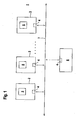
- FIG. 1 schematically shows a bus system 1 within a motor vehicle, to which a plurality of control devices 2 are connected, which generally form electronic units and exchange data as bus subscribers via the bus system 1 by sending messages.
- Such a bus system 1 of a motor vehicle may generally also comprise a configuration of a plurality of data buses, typically in motor vehicles CAN buses and LIN buses are used.
- the control units 2 of the motor vehicle form, for example, units for providing or monitoring vehicle functions. Example of this are control devices 2 for the brake, clutch or steering of a motor vehicle.
- bus system 1 is shown greatly simplified and shows a predetermined number of control units 2, which are connected to each other via bus lines 3.
- Each control unit 2 has a bus interface 4 for connection to the bus system 1.
- Such controllers 2 generally form electronic units with at least one computer unit and with storage media for storing data.
- each control unit 2 in addition to at least one volatile memory such as a RAM and at least one non-volatile memory such as a flash or EEPROM. If security-relevant functions are carried out with the control devices 2, they can have a redundant structure in order to achieve the necessary fault-tolerance.
- the control devices 2 which are used in a motor vehicle are generally designed such that they have free computing and storage capacities. .
- control devices 2 These free capacities of the control devices 2 are exploited by implementing data recording modules 5 therein.
- data recording modules 5 integrated in the control unit 2 form components of a distributed data recording system.
- the analysis unit 6 is not permanent, but only at certain times to the Bus system 1 is connected, which is indicated by the dashed lines lead of the analysis unit 6 to the bus system 1.
- the data recording modules 5 implemented in the individual control devices 2 form software modules which use the computing and storage capacities of the respective control device 2.
- each data recording module 5 uses the free capacity of the non-volatile memory of the controller 2, on which it is integrated, to form a ring memory.
- this ring memory continuously data of the associated control unit 2, in particular from this sent or received messages, non-volatile stored.
- the size of the ring memory is adapted to the free storage capacity of the associated control unit 2.
- the individual data recording modules 5 for this purpose are divided in a suitable manner to the control units 2 and specified in terms of their functionality in a suitable manner.
- the logging of messages of the individual control units 2 by the data recording modules 5 implemented therein serves to detect and analyze errors in the individual control units 2 or in the transmission of messages via the bus system 1.
- a data recording module 5 can be implemented in each control device 2. In general, only in a predetermined part of the control units 2 data recording modules 5 can be integrated.
- the operation of the distributed data recording system is such that during operation of the bus system 1, the individual data recording modules 5, the data of the associated control units 2, in particular the transmitted and received messages, read continuously and are written into the ring buffer. If a predefined trigger condition is fulfilled, data of the ring buffer are not stored volatile.
- the non-volatile storage of data can be done locally by the data of the ring buffer of the data recording module 5 are stored in the non-volatile memory of the controller 2 in which this data recording module 5 is implemented.
- a central storage is possible by, for example, the data of the ring memory of all data recording modules 5 are stored in the non-volatile memory of a control unit 2.
- the non-volatile storage of data can be done in the simplest case such that at the time of fulfillment of the trigger condition, the entire contents of a ring memory is stored non-volatile.
- the non-volatile storage can be carried out such that the data of the ring memory from a defined time before the fulfillment of the trigger condition until a defined time after the fulfillment of the trigger condition are transferred to the non-volatile memory.
- the extent of the non-volatile stored data can be dependent on the respective trigger condition.
- the analysis unit 6 is on the bus system 1 connected.
- the trigger conditions are adapted to the distributed structure of the data recording system and are each formed by a number of local trigger conditions for individual data recording modules 5.
- Each local trigger condition for a data recording module 5 defines a setpoint for a particular variable or parameter in the controller 2 itself, in which the data recording module 5 is integrated, or in a message received or transmitted by that controller 2.
- a trigger condition can be defined by the fact that for all or only for a part of the data recording modules 5 local trigger conditions are given.
- this reserved message consists of individual trigger fields for the individual local trigger conditions.
- a trigger field is set if the corresponding local trigger condition is fulfilled.
- the entire trigger condition is fulfilled when all trigger fields are set, that is, when the messages of all the data recording modules 5 that their local trigger conditions are met are contained in the reserved message. If several trigger conditions are specified, a reserved message with a corresponding number of trigger fields can be exchanged for each of these trigger conditions.
- the trigger conditions are generally chosen so that they are adapted to certain types of errors, so that the trigger conditions are met in certain error situations. Further, since the nature and extent of the non-volatile stored data are adapted to the trigger conditions, they provide immediate information about any errors that have occurred in the control units 2 or in the messages sent via the bus system 1.
- the analysis unit 6 can be connected to the bus system 1 of the motor vehicle at a predetermined time. For example, it can be detected while driving a motor vehicle with a counter, how often a trigger condition has been met. If a certain number of trigger conditions has been met, that is, if a certain number of error situations have been detected, a message can be sent to the driver of the motor vehicle be issued that he should visit a workshop. There, the analysis unit 6 is then connected to the bus system 1 of the motor vehicle and it is the non-volatile stored data of the individual data recording modules 5 read and evaluated.
- a defined time reference of messages of different data recording modules 5 can be established by tracing back the time sequence of the sending of messages between the data recording modules 5. For example, a chronological sequence of messages is obtained by analyzing which messages form responses or responses to previous messages. In general, a chronological sequence of messages can be obtained by providing them with unique time stamps. From the non-volatile stored data to a trigger condition results in a complete image of the traffic between the control units 2 in exactly the time range in which the error has occurred. This is because the trigger time corresponds to the time the error occurred and the data is recorded in a time range around this trigger time. This allows a precise analysis of the error that has occurred.
Description
Die Erfindung betrifft ein Verfahren zum Aufzeichnen von Daten und ein Datenaufzeichnungssystem.The invention relates to a method for recording data and a data recording system.
Ein derartiges Verfahren beziehungsweise Datenaufzeichnungssystem dient generell zum Aufzeichnen von Daten, welche zwischen Elektronikeinheiten als Busteilnehmern eines Bussystems übertragen werden, wobei ein derartiges Bussystem von einem Datenbus eines Kraftfahrzeugs gebildet ist. Dort sind die Elektronikeinheiten von Steuergeräten, mit welchen verschiedene Fahrzeugfunktionen realisiert oder überwacht werden, gebildet.Such a method or data recording system is generally used for recording data which are transmitted between electronic units as bus subscribers of a bus system, wherein such a bus system is formed by a data bus of a motor vehicle. There, the electronic units of control units, with which various vehicle functions are realized or monitored, formed.
Ein derartiges Verfahren zum Mitprotokollieren von Nachrichten auf einem Datenbus eines Kraftfahrzeugs ist aus der
Mittels des ablauffähigen Programms im Übertragungssystem werden die Nachrichten, die über den Datenbus des Kraftfahrzeugs ausgetauscht werden, mitgelesen und in dem flüchtigen Speicher, der vorzugsweise als Ringspeicher ausgebildet ist, zwischengespeichert. Wird von dem ablauffähigen Programm ein bestimmtes Triggerereignis registriert, wird das Überschreiben des flüchtigen Speichers gestoppt um dann den Inhalt des flüchtigen Speichers in den nicht flüchtigen Speicher zu übertragen. Das Triggerereignis kann dabei aus einem einzelnen Merkmal oder aus einer Kombination oder Folge von Merkmalen gebildet sein, die über die Datenbusse übertragen werden.By means of the executable program in the transmission system, the messages that are exchanged via the data bus of the motor vehicle, read and stored in the volatile memory, which is preferably designed as a ring buffer. If the executable program registers a specific trigger event, the overwrite of the volatile Memory stopped to then transfer the contents of the volatile memory in the non-volatile memory. The trigger event can be formed from a single feature or from a combination or sequence of features that are transmitted via the data buses.
Anhand der im Übertragungssystem auf diese Weise nicht flüchtig gespeicherten Daten wird eine Rückverfolgbarkeit des Busverkehrs insbesondere bei Auftreten von Fehlern erzielt. Anhand der nicht flüchtig gespeicherten Daten können nämlich über den Datenbus ausgetauschte Nachrichten zurück verfolgt werden, um festzustellen von welchem am Datenbus angeschlossenen Steuergerät eine fehlerhafte Nachricht versendet wurde.Traceability of the bus traffic is achieved on the basis of the nonvolatile data stored in the transmission system in this way, especially if errors occur. On the basis of the non-volatile data stored messages that are exchanged over the data bus can be traced back to determine from which connected to the data bus control unit a faulty message was sent.
Nachteilig hierbei ist, dass das Übertragungssystem als separate Einheit an den Datenbus des Kraftfahrzeugs angeschlossen werden muss, was mit einem zusätzlichen konstruktiven Aufwand verbunden ist.The disadvantage here is that the transmission system must be connected as a separate unit to the data bus of the motor vehicle, which is associated with an additional design effort.
Die
Die
Die
Die
Die
Der Erfindung liegt die Aufgabe zugrunde, ein Verfahren und ein Datenaufzeichnungssystem bereitzustellen, mittels dessen mit möglichst geringem Aufwand eine möglichst sichere und umfassende Kontrolle eines Bussystems und der an dieses angeschlossenen Elektronikeinheiten ermöglicht wird.The invention has for its object to provide a method and a data recording system, by means of which with the least possible effort the most secure and comprehensive control of a bus system and connected to this electronic units is possible.
Zur Lösung dieser Aufgabe sind die Merkmale der Ansprüche 1 und 12 vorgesehen. Vorteilhafte Ausführungsformen und zweckmäßige Weiterbildungen der Erfindung sind in den Unteransprüchen beschrieben.To achieve this object, the features of
Das erfindungsgemäße Verfahren dient zum Aufzeichnen von Daten, welche zwischen Elektronikeinheiten als Busteilnehmern eines Bussystems eines Kraftfahrzeugs übertragen werden, und/oder welche in Busteilnehmern intern generiert oder vorhanden sind. Es ist eine Anzahl von Datenaufzeichnungsmodulen vorgesehen, von welchen jeweils eines in einer Elektronikeinheit implementiert wird. Jedes Datenaufzeichnungsmodul weist einen Ringspeicher auf. Die Ausbildung der Datenaufzeichnungsmodule sowie deren Aufteilungen auf die Elektronikeinheiten sind an deren freie Rechen- und Speicherkapazitäten angepasst. Jedes Datenaufzeichnungsmodul schreibt fortlaufend Daten der Elektronikeinheit, in welcher es implementiert ist, in einen Ringspeicher ein. Bei Vorliegen einer Triggerbedingung werden Daten der Ringspeicher der Datenaufzeichnungsmodule nicht flüchtig gespeichert. Diese Triggerbedingung liegt vor, wenn mehrere lokale Triggerbedingungen, die für einzelne verschiedene Datenaufzeichnungsmodule vorgegeben sind, erfüllt sind. Zur Überprüfung ob die oder eine Triggerbedingung erfüllt ist, tauschen die Datenaufzeichnungsmodule über das Bussystem untereinander eine reservierte Nachricht aus. In dieser teilt ein Datenaufzeichnungsmodul den anderen Datenaufzeichnungsmodulen mit, wenn dessen lokale Triggerbedingung erfüllt ist.The method according to the invention serves to record data which is transmitted between electronic units as bus subscribers of a bus system of a motor vehicle, and / or which are internally generated or present in bus subscribers. A number of data recording modules are provided, one of which is implemented in an electronics unit. Each data recording module has a ring memory. The design of the data recording modules and their distribution to the electronic units are adapted to their free computing and storage capacities. Each data logging module continuously encrypts data of the electronics unit in which it is implemented into a ring buffer. If a trigger condition exists, data of the ring memories of the data recording modules are not stored volatile. This trigger condition occurs when multiple local trigger conditions specified for individual different data recording modules are met. To check whether the or a trigger condition is met, the data recording modules exchange a reserved message with each other via the bus system. In this, a data logger communicates to the other data logger modules if its local trigger condition is met.
Das Ablegen der Daten kann in Form einer nicht flüchtigen Speicherung der Daten erfolgen. Alternativ kann das Ablegen der Daten zunächst in Form einer flüchtigen Speicherung der Daten erfolgen, wobei gewährleistet ist, dass diese Daten nicht überschrieben werden. Um die Daten sichern zu können werden diese dann zu einem späteren Zeitpunkt, insbesondere vor einer Stromabschaltung des Systems, an eine externe Einheit ausgelesen und dort nicht flüchtig gespeichert.The data can be stored in the form of non-volatile storage of the data. Alternatively, the storage of the data may initially take the form of a volatile storage of the data, whereby it is ensured that this data is not overwritten. To be able to save the data these are then read at a later time, in particular before a power cut of the system to an external unit and stored there not volatile.
Mit dem erfindungsgemäßen Verfahren und dem erfindungsgemäßen Datenaufzeichnungssystem wird eine umfangreiche Diagnosemöglichkeit bei Auftreten von Fehlern im Datenverkehr des Bussystems ermöglicht. Da weiterhin auch interne Daten der Busteilnehmer aufgezeichnet werden, kann auch für diese selbst eine umfangreiche Diagnose durchgeführt werden. Durch Vorgabe geeigneter Triggerbedingungen und das Ablegen von mitprotokollierten Daten in den Ringspeichern bei erfüllten Triggerbedingungen kann durch eine Analyse dieser abgelegten Daten die Ursache für das Auftreten eines Fehlers gezielt analysiert werden. Die Triggerbedingungen können beispielsweise so gewählt werden, dass diese bei Auftreten spezifischer Fehlfunktionen erfüllt sind, so dass dann die abgelegten Daten gerade den Zeitraum umfassen, in welchem ein zu analysierender Fehler aufgetreten ist. Die abgelegten Daten stellen dann eine relativ kleine und mit überschaubarem Aufwand auszuwertende Datenmenge dar. Da die abgelegten Daten durch die Vorgabe der Triggerbedingungen in engem zeitlichen Bezug zum Auftreten des Fehlers stehen, kann durch die Auswertung dieser Daten die Ursache des Fehlers mit hoher Sicherheit bestimmt werden.With the method according to the invention and the data recording system according to the invention, a comprehensive diagnostic option is possible when errors occur in the data traffic of the bus system. Since internal data of the bus subscribers are also recorded, a comprehensive diagnosis can also be carried out for them. By specifying suitable trigger conditions and storing logged data in the ring memories under fulfilled trigger conditions, the cause of the occurrence of a fault can be analyzed in a targeted manner by analyzing this stored data. The trigger conditions can be selected, for example, such that they are met when specific malfunctions occur, so that then the stored data just include the period in which an error to be analyzed has occurred. The stored data then represent a relatively small amount of data to be evaluated with reasonable effort. Since the stored data are closely related to the occurrence of the error due to the specification of the trigger conditions, the cause of the error can be determined with high reliability by evaluating this data ,
Der Grundgedanke der Erfindung besteht darin, dass das Datenaufzeichnungssystem zum Mitprotokollieren von Nachrichten des Bussystems keine isolierte, externe Einheit bildet, die zusätzlich zu den Elektronikeinheiten an das Bussystem angeschlossen wird. Vielmehr bildet das Datenaufzeichnungssystem ein verteiltes System, welches aus Datenaufzeichnungsmodulen besteht, die in den einzelnen Elektronikeinheiten des Bussystems implementiert werden. Dabei wird der Umstand ausgenutzt, dass Elektronikeinheiten oder Steuergeräte als spezielle Elektronikeinheiten in einem Kraftfahrzeug, generell für den Einsatz in Automatisierungssystemen so ausgelegt werden, dass diese noch freie Rechen- und Speicherkapazitäten aufweisen. Erfindungsgemäß sind die Funktionalitäten der Datenaufzeichnungsmodule und deren Aufteilung auf die Elektronikeinheit an die dort verfügbaren freien Rechen- und Speicherkapazitäten angepasst, wodurch einerseits die Rechen- und Speicherkapazitäten der Elektronikeinheiten optimal genutzt werden und andererseits auch die Funktionalität der Datenaufzeichnungsmodule optimiert wird.The basic idea of the invention is that the data recording system for logging messages of the bus system does not form an isolated, external unit which is connected to the bus system in addition to the electronic units. Rather, the data recording system is a distributed system consisting of data recording modules that are implemented in the individual electronic units of the bus system. It exploits the fact that electronic units or control units are designed as special electronic units in a motor vehicle, generally for use in automation systems, so that they still have free computing power. and have storage capacities. According to the functionalities of the data recording modules and their allocation to the electronic unit are adapted to the available there free computing and storage capacities, whereby on the one hand, the computing and storage capacities of the electronic units are optimally used and on the other hand, the functionality of the data recording modules is optimized.
Durch die erfindungsgemäße Ausbildung des Datenaufzeichnungssystems in Form der Datenaufzeichnungsmodule wird keine externe Einheit zum Mitprotokollieren der Nachrichten auf dem Bussystem mehr benötigt, wodurch der Hardwareaufwand des Datenaufzeichnungssystems erheblich reduziert wird. Das verteilte Datenaufzeichnungssystem eignet sich damit zum Einsatz in Kraftfahrzeugen, da dort zusätzliche Überwachungseinheiten mangels vorhandenen Platzes und letztlich auch aufgrund anfallender Zusatzkosten im Allgemeinen nur in Prototypen-Fahrzeugen, nicht jedoch in Serien-Fahrzeugen akzeptiert werden.The inventive design of the data recording system in the form of data recording modules, an external unit for logging messages on the bus system is no longer needed, whereby the hardware cost of the data recording system is significantly reduced. The distributed data recording system is thus suitable for use in motor vehicles, since additional monitoring units are accepted there due to lack of available space and ultimately also due to additional costs generally only in prototype vehicles, but not in production vehicles.
Die Triggerbedingungen sind an die Ausbildung des Datenaufzeichnungssystems als verteiltes System derart angepasst, dass mehrere lokale Triggerbedingungen, die für einzelne Datenaufzeichnungsmodule vorgegeben sind, eine Triggerbedingung bilden. Eine lokale Triggerbedingung ist beispielsweise dann erfüllt, wenn für eine Nachricht eines Datenaufzeichnungsmoduls oder für einen bestimmten Parameter des Datenaufzeichnungsmoduls eine bestimmte Bedingung erfüllt ist. Generell kann dabei für alle Datenaufzeichnungsmodule oder nur für eine Teilmenge von Datenaufzeichnungsmodulen eine solche lokale Triggerbedingung definiert werden. Die Definition derartiger lokaler Triggerbedingungen erfolgt bevorzugt in einer Initialisierungsphase über eine externe Einheit, insbesondere in einer Analyseeinheit, die auch zur Messwertauswertung, das heißt zur Fehleranalyse, verwendet wird. Dabei muss diese externe Einheit nur während der Initialisierungsphase an das Bussystem angeschlossen werden, nicht jedoch während dessen Betriebs.The trigger conditions are adapted to the formation of the data recording system as a distributed system such that multiple local trigger conditions, which are predetermined for individual data recording modules, form a trigger condition. A local trigger condition is satisfied, for example, when a message of a data recording module or for a particular parameter of the data recording module a certain condition is met. In general, such a local trigger condition can be defined for all data recording modules or only for a subset of data recording modules. The definition of such local trigger conditions preferably takes place in an initialization phase via an external unit, in particular in an analysis unit which is also used for the evaluation of the measured value, that is to say for error analysis. In this case, this external unit must be connected to the bus system only during the initialization phase, but not during its operation.
Zur Überprüfung, ob die oder eine Triggerbedingung erfüllt ist, tauschen die Datenaufzeichnungsmodule über das Bussystem untereinander eine reservierte Nachricht aus. In dieser teilt ein Datenaufzeichnungsmodul dem anderen Datenaufzeichnungsmodul mit, wenn dessen lokale Triggerbedingung erfüllt ist. Die Triggerbedingung ist erfüllt, wenn in der reservierten Nachricht die Mitteilungen aller Datenaufzeichnungsmodule, dass deren lokale Triggerbedingungen erfüllt sind, enthalten sind.To check whether the or a trigger condition is met, the data recording modules exchange a reserved message with one another via the bus system. In this one data recording module notifies the other data recording module if its local trigger condition is met. The trigger condition is fulfilled if the messages contained in the reserved message contain the messages of all the data recording modules that fulfill their local trigger conditions.
Die aus den lokalen Triggerbedingungen gebildeten Triggerbedingungen können an die Ausbildung der Datenaufzeichnungsmodule in optimaler Weise angepasst werden, wodurch erreicht wird, dass die Triggerbedingungen in spezifischen Fehlerfunktionen erfüllt sind, so dass dann gezielt zu den Fehlerzeitpunkten Daten abgelegt werden können, um dann anhand dieser Daten die Entstehung und Ursachen von Fehlern analysieren zu können.The trigger conditions formed from the local trigger conditions can be optimally adapted to the formation of the data recording modules, whereby it is achieved that the trigger conditions are fulfilled in specific error functions so that data can then be stored selectively at the error times, in order then to use the data Being able to analyze the origins and causes of errors.
Der Umfang der Daten, die abgelegt werden, kann dabei vorteilhaft von den Triggerbedingungen abhängig sein, wodurch für spezifische Fehlersituationen die zur Fehleranalyse benötigten Daten optimal gewählt werden können.The extent of the data that is stored can advantageously depend on the trigger conditions, whereby the data required for error analysis can be optimally selected for specific error situations.
Das Ablegen der Daten, insbesondere deren nicht flüchtige Speicherung kann an die Gegebenheiten des Bussystems flexibel angepasst werden. Je nach verfügbarer Speicher- und Rechenkapazität der einzelnen Elektronikeinheiten des Bussystems kann das Ablegen der Daten lokal in den Speichern der Elektronikeinheiten, in welchen die Datenaufzeichnungsmodule integriert sind, erfolgen. Alternativ kann eine leistungsstarke Elektronikeinheit zur zentralen Speicherung aller Daten genutzt werden.The storage of data, in particular their non-volatile storage can be flexibly adapted to the conditions of the bus system. Depending on the available memory and computing capacity of the individual electronic units of the bus system, the storage of the data can be done locally in the memories of the electronic units in which the data recording modules are integrated. Alternatively, a powerful electronic unit can be used for central storage of all data.
Bei dem erfindungsgemäßen Datenaufzeichnungssystem wird vorteilhaft eine externe Einheit in Form einer Analyseeinheit nur zur Initialisierung der Triggerbedingung und zur Auswertung der abgelegten Daten benötigt. Beide Funktionen sind zeitlich unabhängig von dem Mitprotokollieren der Daten mit den Datenaufzeichnungsmodulen und können daher unabhängig von diesen zu frei wählbaren Zeiten durchgeführt werden.In the data recording system according to the invention, an external unit in the form of an analysis unit is advantageously required only for the initialization of the trigger condition and for the evaluation of the stored data. Both functions are time independent of the data logging with the data recording modules and can therefore be performed independently of these at freely selectable times.
Die Erfindung wird im Folgenden anhand eines Ausführungsbeispiels und anhand der Zeichnung erläutert. Es zeigt:
- Figur 1:
- Schematische Darstellung eines Ausführungsbeispiels des erfindungsgemäßen Datenaufzeichnungssystems.
- FIG. 1:
- Schematic representation of an embodiment of the data recording system according to the invention.
Ein derartiges Bussystem 1 eines Kraftfahrzeugs kann generell auch eine Konfiguration mehrer Datenbusse umfassen, wobei typischerweise in Kraftfahrzeugen CAN-Busse und LIN-Busse eingesetzt werden. Die Steuergeräte 2 des Kraftfahrzeugs bilden beispielsweise Einheiten zur Bereitstellung oder Überwachung von Fahrzeugfunktionen. Beispiel hierfür sind Steuergeräte 2 für die Bremse, Kupplung oder Lenkung eines Kraftfahrzeugs.Such a
Das in
Derartige Steuergeräte 2 bilden generell Elektronikeinheiten mit wenigstens einer Rechnereinheit sowie mit Speichermedien zum Speichern von Daten. Dabei weist vorzugsweise jedes Steuergerät 2 neben wenigstens einem flüchtigen Speicher wie zum Beispiel einem RAM auch einen wenigstens einen nicht flüchtigen Speicher wie einem Flash oder EEPROM auf. Wenn mit den Steuergeräten 2 sicherheitsrelevante Funktionen ausgeführt werden, können diese zur Erzielung der notwendigen Fehlersicherheit einen redundanten Aufbau aufweisen.
Die Steuergeräte 2, die in einem Kraftfahrzeug eingesetzt werden, sind generell derart ausgelegt, dass diese über freie Rechen- und Speicherkapazitäten verfügen. ,The
Diese freien Kapazitäten der Steuergeräte 2 werden dadurch ausgenützt, dass in diesem Datenaufzeichnungsmodule 5 implementiert werden. Diese in dem Steuergerät 2 integrierten Datenaufzeichnungsmodule 5 bilden Komponenten eines verteilten Datenaufzeichnungssystems. Als weitere Komponenten des Datenaufzeichnungssystems ist als externe, an das Bussystem 1 anschließbare Einheit eine Analyseeinheit 6 vorgesehen, die allgemein von einer Rechnereinheit gebildet ist und eine Busschnittstelle 4 zum Anschluss aufweist. Die Analyseeinheit 6 ist nicht dauernd, sondern nur zu bestimmten Zeitpunkten an das Bussystem 1 angeschlossen, was durch die gestrichelt dargestellte Zuleitung der Analyseeinheit 6 zum Bussystem 1 angedeutet ist.These free capacities of the
Die in den einzelnen Steuergeräten 2 implementierten Datenaufzeichnungsmodule 5 bilden Software-Module, die die Rechen- und Speicherkapazitäten des jeweiligen Steuergeräts 2 nutzen. Insbesondere nutzt jedes Datenaufzeichnungsmodul 5 die freie Kapazität des nicht flüchtigen Speichers des Steuergeräts 2, auf welchem dieses integriert ist, um einen Ringspeicher auszubilden. In diesem Ringspeicher werden fortlaufend Daten des zugeordneten Steuergeräts 2, insbesondere von diesem ausgesandte oder empfangene Nachrichten, nicht flüchtig gespeichert.The
Die Größe des Ringspeichers ist an die freie Speicherkapazität des zugeordneten Steuergeräts 2 angepasst. Bei der Implementierung werden die einzelnen Datenaufzeichnungsmodule 5 hierzu in geeigneter Weise auf die Steuergeräte 2 aufgeteilt und in geeigneter Weise hinsichtlich ihrer Funktionalität spezifiziert.The size of the ring memory is adapted to the free storage capacity of the associated
Das Mitprotokollieren von Nachrichten der einzelnen Steuergeräte 2 durch die in diesen implementierten Datenaufzeichnungsmodulen 5 dient dazu, Fehler in den einzelnen Steuergeräten 2 oder in der Übertragung von Nachrichten über das Bussystem 1 zu erkennen und zu analysieren. Um eine möglichst umfassende Analyse zu erhalten, kann in jedem Steuergerät 2 ein Datenaufzeichnungsmodul 5 implementiert sein. Generell können auch nur in einem vorgegebenen Teil der Steuergeräte 2 Datenaufzeichnungsmodule 5 integriert sein.The logging of messages of the
Die Funktionsweise des verteilten Datenaufzeichnungssystems ist derart, dass während des Betriebs des Bussystems 1 die einzelnen Datenaufzeichnungsmodule 5 die Daten der zugeordneten Steuergeräte 2, insbesondere die gesendeten und empfangenen Nachrichten, fortlaufend mitgelesen und in den Ringspeicher eingeschrieben werden. Ist eine vorgegebene Triggerbedingung erfüllt, so werden Daten der Ringspeicher nicht flüchtig gespeichert. Generell kann die nicht flüchtige Speicherung der Daten lokal erfolgen, indem die Daten des Ringspeichers des Datenaufzeichnungsmoduls 5 in dem nicht flüchtigen Speicher des Steuergeräts 2, in dem dieses Datenaufzeichnungsmodul 5 implementiert ist, abgespeichert werden. Alternativ ist auch eine zentrale Speicherung möglich, indem beispielsweise die Daten der Ringspeicher aller Datenaufzeichnungsmodule 5 in dem nicht flüchtigen Speicher eines Steuergeräts 2 abgespeichert werden.The operation of the distributed data recording system is such that during operation of the
Die nicht flüchtige Speicherung von Daten kann im einfachsten Fall derart erfolgen, dass zum Zeitpunkt der Erfüllung der Triggerbedingung der gesamte Inhalt eines Ringspeichers nicht flüchtig gespeichert wird. Alternativ kann die nicht flüchtige Speicherung derart erfolgen, dass die Daten des Ringspeichers von einem definierten Zeitpunkt vor Erfüllung der Triggerbedingung bis zu einem definierten Zeitpunkt nach Erfüllung der Triggerbedingung in den nicht flüchtigen Speicher übertragen werden. Generell kann der Umfang der nicht flüchtig gespeicherten Daten abhängig von der jeweiligen Triggerbedingung sein.The non-volatile storage of data can be done in the simplest case such that at the time of fulfillment of the trigger condition, the entire contents of a ring memory is stored non-volatile. Alternatively, the non-volatile storage can be carried out such that the data of the ring memory from a defined time before the fulfillment of the trigger condition until a defined time after the fulfillment of the trigger condition are transferred to the non-volatile memory. In general, the extent of the non-volatile stored data can be dependent on the respective trigger condition.
Die Festlegung der Art und des Umfangs der nicht flüchtigen Speicherung sowie die Festlegung der Triggerbedingung erfolgt während einer Initialisierungsphase über eine externe Einheit, vorzugsweise der Analyseeinheit 6. Während dieser Initialisierungsphase, nicht jedoch während des darauf folgenden Betriebs des Bussystems 1, ist die Analyseeinheit 6 an das Bussystem 1 angeschlossen.The definition of the type and scope of the non-volatile storage and the determination of the trigger condition during an initialization phase via an external unit, preferably the analysis unit 6. During this initialization phase, but not during the subsequent operation of the
Die Triggerbedingungen sind an die verteilte Struktur des Datenaufzeichnungssystems angepasst und sind jeweils von einer Anzahl von lokalen Triggerbedingungen für einzelne Datenaufzeichnungsmodule 5 gebildet. Jede lokale Triggerbedingung für ein Datenaufzeichnungsmodul 5 definiert einen Sollwert für eine bestimmte Variable oder einen Parameter in dem Steuergerät 2 selbst, in welchem das Datenaufzeichnungsmodul 5 integriert ist, oder in einer Nachricht, die von diesem Steuergerät 2 empfangen oder gesendet wird. Generell kann eine derartige Triggerbedingung dadurch definiert werden, dass für alle oder nur für einen Teil der Datenaufzeichnungsmodule 5 lokale Triggerbedingungen vorgegeben werden.The trigger conditions are adapted to the distributed structure of the data recording system and are each formed by a number of local trigger conditions for individual
Während des auf die Initialisierungsphase folgenden Betriebs des Bussystems 1 erfolgt die Überprüfung, ob eine Triggerbedingung erfüllt ist derart, dass die Datenaufzeichnungsmodule 5 untereinander eine reservierte Nachricht austauschen, wobei in dieser ein Datenaufzeichnungsmodul 5 dem anderen Datenaufzeichnungsmodul 5 mitteilt, wenn dessen lokale Triggerbedingung erfüllt ist. Generell besteht diese reservierte Nachricht aus einzelnen Triggerfeldern für die einzelnen lokalen Triggerbedingungen. Dabei wird jeweils ein Triggerfeld gesetzt, wenn die entsprechende lokale Triggerbedingung erfüllt ist. Die gesamte Triggerbedingung ist dann erfüllt, wenn alle Triggerfelder gesetzt sind, das heißt wenn in der reservierten Nachricht die Mitteilungen aller Datenaufzeichnungsmodule 5, dass deren lokale Triggerbedingungen erfüllt sind, enthalten sind. Sind mehrere Triggerbedingungen vorgegeben, so kann für jede dieser Triggerbedingungen eine reservierte Nachricht mit einer entsprechenden Anzahl von Triggerfeldern ausgetauscht werden.During the operation of the
Die Triggerbedingungen sind generell so gewählt, dass sie an bestimmte Fehlerarten angepasst sind, so dass die Triggerbedingungen jeweils in bestimmten Fehlersituationen erfüllt sind. Da weiterhin Art und Umfang der nicht flüchtig gespeicherten Daten an die Triggerbedingungen angepasst sind, liefern diese unmittelbar Informationen über eventuell aufgetretene Fehler in den Steuergeräten 2 beziehungsweise in den über das Bussystem 1 versendeten Nachrichten.The trigger conditions are generally chosen so that they are adapted to certain types of errors, so that the trigger conditions are met in certain error situations. Further, since the nature and extent of the non-volatile stored data are adapted to the trigger conditions, they provide immediate information about any errors that have occurred in the
Die Auswertung der nicht flüchtig gespeicherten Daten erfolgt in der Analyseeinheit 6. Hierzu kann die Analyseeinheit 6 zu einem vorgegebenen Zeitpunkt an das Bussystem 1 des Kraftfahrzeugs angeschlossen werden. Beispielsweise kann während der Fahrt eines Kraftfahrzeugs mit einem Zähler erfasst werden, wie oft eine Triggerbedingung erfüllt wurde. Wurde eine bestimmte Anzahl von Triggerbedingungen erfüllt, das heißt wurde eine bestimmte Anzahl von Fehlersituationen erkannt, so kann an den Fahrer des Kraftfahrzeugs eine Meldung ausgegeben werden, dass er eine Werkstatt aufsuchen soll. Dort wird dann die Analyseeinheit 6 an das Bussystem 1 des Kraftfahrzeugs angeschlossen und es werden die nicht flüchtig gespeicherten Daten der einzelnen Datenaufzeichnungsmodule 5 ausgelesen und ausgewertet. Ein definierter zeitlicher Bezug von Nachrichten unterschiedlicher Datenaufzeichnungsmodule 5 kann dadurch hergestellt werden, dass der zeitliche Ablauf des Versendens von Nachrichten zwischen den Datenaufzeichnungsmodulen 5 zurück verfolgt wird. So wird beispielsweise eine chronologische Abfolge von Nachrichten erhalten, indem analysiert wird, welche Nachrichten Antworten oder Reaktionen auf vorherige Nachrichten bilden. Generell kann eine zeitliche Abfolge von Nachrichten dadurch erhalten werden, dass diese mit eindeutigen Zeitstempeln versehen werden. Aus den nicht flüchtig gespeicherten Daten zu einer Triggerbedingung ergibt sich ein vollständiges Abbild des Datenverkehrs zwischen den Steuergeräten 2 in genau dem Zeitbereich, in dem der Fehler aufgetreten ist. Dies beruht darauf, dass der Triggerzeitpunkt dem Zeitpunkt des Auftretens des Fehlers entspricht, und dass die Aufzeichnung der Daten in einem Zeitbereich um diesen Triggerzeitpunkt herum erfolgt. Dadurch wird eine genaue Analyse des jeweils aufgetretenen Fehlers möglich.The evaluation of the non-volatile stored data is carried out in the analysis unit 6. For this purpose, the analysis unit 6 can be connected to the
- (1) Bussystem(1) Bus system
- (2) Steuergerät(2) control unit
- (3) Busleitung(3) bus line
- (4) Busschnittstelle(4) Bus interface
- (5) Datenaufzeichnungsmodul(5) Data recording module
- (6) Analyseeinheit(6) analysis unit
Claims (13)
- Method of recording data, which is transferred between electronic units as bus subscribers of a bus system of a motor vehicle, and/or which are internally generated or present in bus subscribers, wherein a plurality of data recording modules (5) is provided, each of which is implemented in an electronic unit, wherein each data recording module (5) comprises a ring memory, wherein the construction of the data recording modules (5) as well as the apportioning thereof to the electronic units are matched to the free computing and storage capacities thereof and wherein each data recording module (5) continuously writes data of the electronic unit, in which it is implemented, into a ring memory, and that in the presence of a trigger condition data of the ring memory of the data recording modules (5) are stored in non-volatile manner, wherein the trigger condition is present when a plurality of local trigger conditions predetermined for individual, different data recording modules (5) is fulfilled and wherein for checking whether the or a trigger condition is fulfilled the data recording modules (5) exchange with one another by way of the bus system (1) a reserved message in which a data recording module (5) informs the other data recording modules (5) when its local trigger condition is fulfilled.
- Method according to claim 1, characterised in that the data recording modules (5) are formed by software modules.
- Method according to one of claims 1 and 2, characterised in that one or more trigger conditions is or are predetermined by an external unit.
- Method according to claim 3, characterised in that the external unit is formed by an analysis unit (6) which is connectible with the bus system (1) and in which evaluation of the filed data is carried out.
- Method according to claim 4, characterised in that local trigger conditions are input into the data recording modules (5) for presetting of the trigger conditions by the analysis unit (6).
- Method according to any one of claims 1 to 5, characterised in that the trigger condition is fulfilled when the communications of all data recording modules (5) to the effect that the local trigger conditions thereof are fulfilled are contained in the reserved message.
- Method according to any one of claims 1 to 6, characterised in that all data of the ring memory are filed or that the data filed in the presence of the or a trigger condition are dependent on this trigger condition.
- Method according to any one of claims 1 to 7, characterised in that data of the ring memory, which are present in a predetermined time interval, are filed, wherein the start of the time interval lies at a defined time before the time instant of the trigger conditions and wherein the end of the time interval lies at a defined time after the time instant of the trigger condition.
- Method according to any one of claims 1 to 8, characterised in that the non-volatile storage of data of the ring memory of a data recording module (5) is carried out locally, wherein for the non-volatile storage of data of the data recording module (5) use is made of a non-volatile memory of the electronic unit in which the data recording module (5) is implemented.
- Method according to claim 9, characterised in that the non-volatile storage of data of the ring memory of a data recording module (5) is carried out centrally in, in particular, an electronic unit.
- Method according to any one of claims 1 to 10, characterised in that the data filed in the presence of a trigger condition are initially stored in non-volatile manner and are stored in a non-volatile manner at a later point in time, wherein, in particular, the filed data for non-volatile storage are transmitted to an external unit.
- Data recording system for recording data, which are transferred between electronic units as bus subscribers of a bus system (1) of a motor vehicle, wherein a plurality of data recording modules (5) is provided, wherein each data recording module (5) is implemented in an electronic unit, wherein the construction of the data recording modules (5) as well as the apportioning thereof to the electronic units are matched to the free computing and storage capacities thereof, wherein each data recording module (5) comprises a ring memory into which data of the electronic units, in which this is implemented, are written, and that in the presence of a trigger condition data of the ring memory of the data recording modules (5) are filed in at least one non-volatile memory, wherein the trigger condition is present when a plurality of local trigger conditions predetermined for individual different data recording modules (5) is fulfilled, and wherein for checking whether the or a trigger condition is fulfilled the data recording modules (5) exchange with one another by way of the bus system (1) a reserved message in which a data recording module (5) informs the other data recording modules (5) when its local trigger condition is fulfilled.
- Data recording system according to claim 12, characterised in that data, which are transferred by way of a bus system (1) of a motor vehicle, are stored by the system and that the electronic units are control apparatus of a motor vehicle.
Applications Claiming Priority (1)
| Application Number | Priority Date | Filing Date | Title |
|---|---|---|---|
| DE102008015352A DE102008015352B4 (en) | 2008-03-22 | 2008-03-22 | Method for recording data and data recording system |
Publications (2)
| Publication Number | Publication Date |
|---|---|
| EP2104075A1 EP2104075A1 (en) | 2009-09-23 |
| EP2104075B1 true EP2104075B1 (en) | 2015-09-09 |
Family
ID=40679372
Family Applications (1)
| Application Number | Title | Priority Date | Filing Date |
|---|---|---|---|
| EP09003242.6A Active EP2104075B1 (en) | 2008-03-22 | 2009-03-06 | Method and device for recording data |
Country Status (3)
| Country | Link |
|---|---|
| EP (1) | EP2104075B1 (en) |
| DE (1) | DE102008015352B4 (en) |
| ES (1) | ES2548296T3 (en) |
Cited By (8)
| Publication number | Priority date | Publication date | Assignee | Title |
|---|---|---|---|---|
| US9183679B2 (en) | 2007-05-08 | 2015-11-10 | Smartdrive Systems, Inc. | Distributed vehicle event recorder systems having a portable memory data transfer system |
| US9208129B2 (en) | 2006-03-16 | 2015-12-08 | Smartdrive Systems, Inc. | Vehicle event recorder systems and networks having integrated cellular wireless communications systems |
| US9226004B1 (en) | 2005-12-08 | 2015-12-29 | Smartdrive Systems, Inc. | Memory management in event recording systems |
| US9402060B2 (en) | 2006-03-16 | 2016-07-26 | Smartdrive Systems, Inc. | Vehicle event recorders with integrated web server |
| US9501878B2 (en) | 2013-10-16 | 2016-11-22 | Smartdrive Systems, Inc. | Vehicle event playback apparatus and methods |
| US9554080B2 (en) | 2006-11-07 | 2017-01-24 | Smartdrive Systems, Inc. | Power management systems for automotive video event recorders |
| US9594371B1 (en) | 2014-02-21 | 2017-03-14 | Smartdrive Systems, Inc. | System and method to detect execution of driving maneuvers |
| US9633318B2 (en) | 2005-12-08 | 2017-04-25 | Smartdrive Systems, Inc. | Vehicle event recorder systems |
Families Citing this family (9)
| Publication number | Priority date | Publication date | Assignee | Title |
|---|---|---|---|---|
| US8989959B2 (en) | 2006-11-07 | 2015-03-24 | Smartdrive Systems, Inc. | Vehicle operator performance history recording, scoring and reporting systems |
| US8868288B2 (en) | 2006-11-09 | 2014-10-21 | Smartdrive Systems, Inc. | Vehicle exception event management systems |
| DE102012204073A1 (en) * | 2012-03-15 | 2013-09-19 | Siemens Aktiengesellschaft | Power supply for a bus of a bus system and bus system |
| US9728228B2 (en) | 2012-08-10 | 2017-08-08 | Smartdrive Systems, Inc. | Vehicle event playback apparatus and methods |
| US9610955B2 (en) | 2013-11-11 | 2017-04-04 | Smartdrive Systems, Inc. | Vehicle fuel consumption monitor and feedback systems |
| US9663127B2 (en) | 2014-10-28 | 2017-05-30 | Smartdrive Systems, Inc. | Rail vehicle event detection and recording system |
| US9679420B2 (en) | 2015-04-01 | 2017-06-13 | Smartdrive Systems, Inc. | Vehicle event recording system and method |
| DE102020108581A1 (en) | 2020-03-27 | 2021-09-30 | Zf Cv Systems Global Gmbh | Data acquisition device for mobile devices, method for carrying out a preliminary analysis in a data acquisition device, vehicle and a correspondingly designed computer program |
| CN111915763A (en) * | 2020-07-24 | 2020-11-10 | 东风汽车有限公司 | Automobile advanced driving assistance function abnormity information acquisition method and electronic equipment |
Family Cites Families (8)
| Publication number | Priority date | Publication date | Assignee | Title |
|---|---|---|---|---|
| DE19546815A1 (en) | 1995-12-15 | 1997-06-19 | Vdo Schindling | Vehicle control system with data storage |
| DE10015318A1 (en) | 1999-03-31 | 2000-11-16 | Bosch Gmbh Robert | Device for affecting initial vehicle values describing initial vehicle movement or vehicle behavior contains regulators and sensors to detect values to be fed to a device for processing input signals |
| DE19933924A1 (en) | 1999-04-29 | 2000-11-02 | Loher Ag | Microsystem for local condition monitoring and condition diagnosis of machines, plants and / or assemblies, especially of drive systems |
| US20040027255A1 (en) | 2002-03-01 | 2004-02-12 | Greenbaum Myron H. | Wideband avionics data retrieval system |
| DE10360125A1 (en) * | 2003-12-20 | 2005-07-21 | Daimlerchrysler Ag | Data loggin in a motor vehicle |
| US7296123B2 (en) * | 2005-02-01 | 2007-11-13 | Delphi Technologies, Inc. | Electronic control unit analysis |
| DE102006018831A1 (en) * | 2006-04-22 | 2007-10-25 | Daimlerchrysler Ag | Vehicle diagnosis and vehicle acceptance |
| DE102006056492A1 (en) | 2006-11-30 | 2008-06-05 | Bayerische Motoren Werke Ag | On-board electrical system for motor vehicle, has program controlled operational data processing device receiving and processing operational data of motor vehicle, where operational data is collected by control devices |
-
2008
- 2008-03-22 DE DE102008015352A patent/DE102008015352B4/en active Active
-
2009
- 2009-03-06 ES ES09003242.6T patent/ES2548296T3/en active Active
- 2009-03-06 EP EP09003242.6A patent/EP2104075B1/en active Active
Cited By (11)
| Publication number | Priority date | Publication date | Assignee | Title |
|---|---|---|---|---|
| US9226004B1 (en) | 2005-12-08 | 2015-12-29 | Smartdrive Systems, Inc. | Memory management in event recording systems |
| US9633318B2 (en) | 2005-12-08 | 2017-04-25 | Smartdrive Systems, Inc. | Vehicle event recorder systems |
| US9208129B2 (en) | 2006-03-16 | 2015-12-08 | Smartdrive Systems, Inc. | Vehicle event recorder systems and networks having integrated cellular wireless communications systems |
| US9402060B2 (en) | 2006-03-16 | 2016-07-26 | Smartdrive Systems, Inc. | Vehicle event recorders with integrated web server |
| US9472029B2 (en) | 2006-03-16 | 2016-10-18 | Smartdrive Systems, Inc. | Vehicle event recorder systems and networks having integrated cellular wireless communications systems |
| US9545881B2 (en) | 2006-03-16 | 2017-01-17 | Smartdrive Systems, Inc. | Vehicle event recorder systems and networks having integrated cellular wireless communications systems |
| US9566910B2 (en) | 2006-03-16 | 2017-02-14 | Smartdrive Systems, Inc. | Vehicle event recorder systems and networks having integrated cellular wireless communications systems |
| US9554080B2 (en) | 2006-11-07 | 2017-01-24 | Smartdrive Systems, Inc. | Power management systems for automotive video event recorders |
| US9183679B2 (en) | 2007-05-08 | 2015-11-10 | Smartdrive Systems, Inc. | Distributed vehicle event recorder systems having a portable memory data transfer system |
| US9501878B2 (en) | 2013-10-16 | 2016-11-22 | Smartdrive Systems, Inc. | Vehicle event playback apparatus and methods |
| US9594371B1 (en) | 2014-02-21 | 2017-03-14 | Smartdrive Systems, Inc. | System and method to detect execution of driving maneuvers |
Also Published As
| Publication number | Publication date |
|---|---|
| EP2104075A1 (en) | 2009-09-23 |
| DE102008015352A1 (en) | 2009-09-24 |
| ES2548296T3 (en) | 2015-10-15 |
| DE102008015352B4 (en) | 2013-12-19 |
Similar Documents
| Publication | Publication Date | Title |
|---|---|---|
| EP2104075B1 (en) | Method and device for recording data | |
| DE102005018301B4 (en) | Data transfer device | |
| DE4320173C2 (en) | Diagnostic methods for motor vehicles for checking electronically controlled systems | |
| EP1796051B1 (en) | Diagnostics devices in a vehicle with diagnostics framework for diagnostics module | |
| DE3810239A1 (en) | Multifunction tester for fault diagnosis | |
| DE102010015132B4 (en) | Data collection method and data collection device for a vehicle | |
| WO2009103387A1 (en) | Method for capturing diagnostic data in a motor vehicle by means of a volatile ring buffer and subsequent data reduction in a non-volatile memory | |
| DE10157188A1 (en) | Programmable data logger and classifier for CAN systems | |
| EP2088439A1 (en) | Device for testing the functionality of a vehicle | |
| WO2008119444A1 (en) | Data recording system and method for acquiring data by means of a data recording system | |
| EP0436818B1 (en) | Diagnostic system for digitally controlled devices | |
| DE202006003273U1 (en) | Function-oriented diagnostic device for motor vehicle, has evaluation unit to evaluates selected signals based on knowledge base information to determine variations and/or consistencies with good or bad attitude of one of vehicle functions | |
| EP2394400B1 (en) | Configurable status processing unit for sensor-actuator systems | |
| DE10307343B4 (en) | On-board diagnostic device and on-board diagnostic procedures for motor vehicles | |
| EP0693726A1 (en) | Method of data transmission in a real-time data processing system | |
| EP2405317B1 (en) | Method for entering parameters for a security device securely | |
| DE102008050506A1 (en) | Method and systems for controlling remote access to a vehicle module | |
| DE19849810A1 (en) | Arrangement for adapting operating data and / or operating programs | |
| EP1117023B1 (en) | Device for fault diagnosis during motor vehicle operation | |
| DE102016009199B4 (en) | Method for operating a data acquisition unit for recording at least one control event of a control device of a motor vehicle as well as a data acquisition unit and a data processing unit | |
| EP0694451B1 (en) | Vehicle security device | |
| DE102016117568B3 (en) | A method of operating a watchdog comprising pattern recognition for recurring load situations | |
| DE102008047561A1 (en) | Control system for motor vehicle, has control devices comprising storage devices for recording data, where triggering device of one of control device is designed to trigger recording process in remaining control devices | |
| DE102012015783A1 (en) | Method for diagnosing several vehicle components of motor car, involves actuating determined diagnostic unit by control device so that supplementary diagnosis data is provided to assigned vehicle component from diagnostic unit | |
| WO2004061405A2 (en) | Method and device for fault analysis of motor vehicle control units and corresponding control unit |
Legal Events
| Date | Code | Title | Description |
|---|---|---|---|
| PUAI | Public reference made under article 153(3) epc to a published international application that has entered the european phase |
Free format text: ORIGINAL CODE: 0009012 |
|
| AK | Designated contracting states |
Kind code of ref document: A1 Designated state(s): AT BE BG CH CY CZ DE DK EE ES FI FR GB GR HR HU IE IS IT LI LT LU LV MC MK MT NL NO PL PT RO SE SI SK TR |
|
| AX | Request for extension of the european patent |
Extension state: AL BA RS |
|
| 17P | Request for examination filed |
Effective date: 20090904 |
|
| 17Q | First examination report despatched |
Effective date: 20091002 |
|
| AKX | Designation fees paid |
Designated state(s): AT BE BG CH CY CZ DE DK EE ES FI FR GB GR HR HU IE IS IT LI LT LU LV MC MK MT NL NO PL PT RO SE SI SK TR |
|
| GRAP | Despatch of communication of intention to grant a patent |
Free format text: ORIGINAL CODE: EPIDOSNIGR1 |
|
| INTG | Intention to grant announced |
Effective date: 20150302 |
|
| GRAS | Grant fee paid |
Free format text: ORIGINAL CODE: EPIDOSNIGR3 |
|
| RBV | Designated contracting states (corrected) |
Designated state(s): AT DE ES FR GB |
|
| RIN1 | Information on inventor provided before grant (corrected) |
Inventor name: BUEHLER, OLIVER Inventor name: ULMER, DANIEL Inventor name: THEISSLER, ANDREAS |
|
| GRAA | (expected) grant |
Free format text: ORIGINAL CODE: 0009210 |
|
| RAP1 | Party data changed (applicant data changed or rights of an application transferred) |
Owner name: STEINBEIS INTERAGIERENDE SYSTEME GMBH |
|
| AK | Designated contracting states |
Kind code of ref document: B1 Designated state(s): AT DE ES FR GB |
|
| REG | Reference to a national code |
Ref country code: GB Ref legal event code: FG4D Free format text: NOT ENGLISH |
|
| RIN1 | Information on inventor provided before grant (corrected) |
Inventor name: ULMER, DANIEL Inventor name: BUEHLER, OLIVER Inventor name: THEISSLER, ANDREAS |
|
| REG | Reference to a national code |
Ref country code: AT Ref legal event code: REF Ref document number: 748678 Country of ref document: AT Kind code of ref document: T Effective date: 20150915 |
|
| REG | Reference to a national code |
Ref country code: DE Ref legal event code: R096 Ref document number: 502009011525 Country of ref document: DE Ref country code: ES Ref legal event code: FG2A Ref document number: 2548296 Country of ref document: ES Kind code of ref document: T3 Effective date: 20151015 |
|
| REG | Reference to a national code |
Ref country code: FR Ref legal event code: PLFP Year of fee payment: 8 |
|
| PGFP | Annual fee paid to national office [announced via postgrant information from national office to epo] |
Ref country code: DE Payment date: 20160312 Year of fee payment: 8 |
|
| REG | Reference to a national code |
Ref country code: DE Ref legal event code: R097 Ref document number: 502009011525 Country of ref document: DE |
|
| PLBE | No opposition filed within time limit |
Free format text: ORIGINAL CODE: 0009261 |
|
| STAA | Information on the status of an ep patent application or granted ep patent |
Free format text: STATUS: NO OPPOSITION FILED WITHIN TIME LIMIT |
|
| 26N | No opposition filed |
Effective date: 20160610 |
|
| REG | Reference to a national code |
Ref country code: FR Ref legal event code: PLFP Year of fee payment: 9 |
|
| REG | Reference to a national code |
Ref country code: DE Ref legal event code: R119 Ref document number: 502009011525 Country of ref document: DE |
|
| PG25 | Lapsed in a contracting state [announced via postgrant information from national office to epo] |
Ref country code: DE Free format text: LAPSE BECAUSE OF NON-PAYMENT OF DUE FEES Effective date: 20171003 |
|
| REG | Reference to a national code |
Ref country code: FR Ref legal event code: PLFP Year of fee payment: 10 |
|
| PGFP | Annual fee paid to national office [announced via postgrant information from national office to epo] |
Ref country code: GB Payment date: 20220113 Year of fee payment: 14 Ref country code: AT Payment date: 20220225 Year of fee payment: 14 |
|
| PGFP | Annual fee paid to national office [announced via postgrant information from national office to epo] |
Ref country code: ES Payment date: 20220405 Year of fee payment: 14 |
|
| PGFP | Annual fee paid to national office [announced via postgrant information from national office to epo] |
Ref country code: FR Payment date: 20230123 Year of fee payment: 15 |
|
| REG | Reference to a national code |
Ref country code: AT Ref legal event code: MM01 Ref document number: 748678 Country of ref document: AT Kind code of ref document: T Effective date: 20230306 |
|
| GBPC | Gb: european patent ceased through non-payment of renewal fee |
Effective date: 20230306 |
|
| PG25 | Lapsed in a contracting state [announced via postgrant information from national office to epo] |
Ref country code: GB Free format text: LAPSE BECAUSE OF NON-PAYMENT OF DUE FEES Effective date: 20230306 |
|
| PG25 | Lapsed in a contracting state [announced via postgrant information from national office to epo] |
Ref country code: GB Free format text: LAPSE BECAUSE OF NON-PAYMENT OF DUE FEES Effective date: 20230306 Ref country code: AT Free format text: LAPSE BECAUSE OF NON-PAYMENT OF DUE FEES Effective date: 20230306 |