EP2219401A2 - System and method for efficiently populating an access point database - Google Patents
System and method for efficiently populating an access point database Download PDFInfo
- Publication number
- EP2219401A2 EP2219401A2 EP10151910A EP10151910A EP2219401A2 EP 2219401 A2 EP2219401 A2 EP 2219401A2 EP 10151910 A EP10151910 A EP 10151910A EP 10151910 A EP10151910 A EP 10151910A EP 2219401 A2 EP2219401 A2 EP 2219401A2
- Authority
- EP
- European Patent Office
- Prior art keywords
- access point
- scan data
- access
- location server
- locations
- Prior art date
- Legal status (The legal status is an assumption and is not a legal conclusion. Google has not performed a legal analysis and makes no representation as to the accuracy of the status listed.)
- Granted
Links
- 238000000034 method Methods 0.000 title claims abstract description 61
- 238000013179 statistical model Methods 0.000 claims description 5
- 230000005540 biological transmission Effects 0.000 claims description 3
- 238000010586 diagram Methods 0.000 description 15
- 238000004364 calculation method Methods 0.000 description 11
- 230000006870 function Effects 0.000 description 10
- 238000005516 engineering process Methods 0.000 description 9
- 230000006854 communication Effects 0.000 description 7
- 238000004891 communication Methods 0.000 description 7
- 238000012545 processing Methods 0.000 description 7
- 238000005259 measurement Methods 0.000 description 3
- 230000008569 process Effects 0.000 description 3
- 230000007175 bidirectional communication Effects 0.000 description 1
- 230000001413 cellular effect Effects 0.000 description 1
- 230000001934 delay Effects 0.000 description 1
- 230000001419 dependent effect Effects 0.000 description 1
- 230000001627 detrimental effect Effects 0.000 description 1
- 230000006872 improvement Effects 0.000 description 1
- 238000004519 manufacturing process Methods 0.000 description 1
- 238000012986 modification Methods 0.000 description 1
- 230000004048 modification Effects 0.000 description 1
- 239000013598 vector Substances 0.000 description 1
Images


Classifications
-
- H—ELECTRICITY
- H04—ELECTRIC COMMUNICATION TECHNIQUE
- H04W—WIRELESS COMMUNICATION NETWORKS
- H04W64/00—Locating users or terminals or network equipment for network management purposes, e.g. mobility management
-
- H—ELECTRICITY
- H04—ELECTRIC COMMUNICATION TECHNIQUE
- H04W—WIRELESS COMMUNICATION NETWORKS
- H04W24/00—Supervisory, monitoring or testing arrangements
- H04W24/02—Arrangements for optimising operational condition
-
- H—ELECTRICITY
- H04—ELECTRIC COMMUNICATION TECHNIQUE
- H04W—WIRELESS COMMUNICATION NETWORKS
- H04W48/00—Access restriction; Network selection; Access point selection
- H04W48/16—Discovering, processing access restriction or access information
-
- H—ELECTRICITY
- H04—ELECTRIC COMMUNICATION TECHNIQUE
- H04W—WIRELESS COMMUNICATION NETWORKS
- H04W64/00—Locating users or terminals or network equipment for network management purposes, e.g. mobility management
- H04W64/003—Locating users or terminals or network equipment for network management purposes, e.g. mobility management locating network equipment
-
- H—ELECTRICITY
- H04—ELECTRIC COMMUNICATION TECHNIQUE
- H04W—WIRELESS COMMUNICATION NETWORKS
- H04W88/00—Devices specially adapted for wireless communication networks, e.g. terminals, base stations or access point devices
- H04W88/08—Access point devices
Definitions
- This invention relates generally to a system and method for efficiently populating an access point database.
- enhanced device capability to perform various advanced operations may provide additional benefits to a device user, but may also place increased demands on the control and management of various device components.
- implementing an enhanced electronic device that effectively provides accurate device-location information to a device user may present certain difficulties because of the unpredictable operating environments that may potentially be encountered.
- mobile devices in an electronic network initially determine their physical location by utilizing any appropriate techniques. For example, the mobile devices may receive transmitted signals from a global positioning system (GPS), and may then utilize the corresponding GPS signals to determine their respective physical locations. The mobile devices each transmit their particular location coordinates to a location server in the electronic network.
- GPS global positioning system
- the mobile devices automatically perform a wireless scanning procedure to detect and store any appropriate access point scan data from access point signals transmitted from one or more access points that are distributed throughout the electronic network.
- the captured access point scan data may include, but is not limited to, access point identifiers and access point signal strengths corresponding to respective access points.
- the mobile devices then transmit the captured access point scan data to the location server by utilizing any appropriate techniques.
- An access point location calculator of the location server utilizes the received access point scan data to perform an access point location procedure.
- the access point location calculator utilizes the received access point scan data to calculate specific access point locations for one or more access points in the electronic network by utilizing any appropriate and effective location calculation techniques.
- the location server then updates the access point database with any new or different access point locations that are discovered as a result of the foregoing access point location procedure. Finally, the location server may transmit the updated access point database to the mobile devices for use in calculating physical locations of the respective mobile devices with respect to the access points. For at least the foregoing reasons, the present invention therefore provides an improved system and method for efficiently populating an access point database.
- the invention relates to techniques for utilizing mobile electronic devices.
- the present invention relates to an improvement in the effective utilization of mobile electronic devices.
- the following description is presented to enable one of ordinary skill in the art to make and use the invention, and is provided in the context of a patent application and its requirements.
- Various modifications to the disclosed embodiments will be readily apparent to those skilled in the art, and the generic principles herein may be applied to other embodiments.
- the present invention is not intended to be limited to the embodiments shown, but is to be accorded the widest scope consistent with the principles and features described herein.
- the present invention is described herein as a system and method for populating an access point database, and includes a network of access points that are implemented to transmit access point signals by utilizing a wireless broadcasting procedure.
- One or more mobile devices are then configured to wirelessly receive and analyze the access point signals to produce access point scan data corresponding to the access points.
- a location server receives and analyzes the access point scan data to determine specific access point locations for the access points. The location server may then utilize the calculated access point locations to populate the access point database.
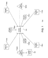
- electronic system 110 may include, but is not limited to, one or more mobile device(s) 114, a plurality of satellites 118, a plurality of base stations 122, a location server 126, and a plurality of access points 130.
- electronic system 110 may be implemented using various components and configurations in addition to, or instead of, those components and configurations discussed in conjunction with the FIG. 1 embodiment.
- FIG. 1 embodiment is implemented with one or more mobile device(s) 114, four satellites 118, two base stations 122, one location server 126, and three access points 130.
- electronic network 110 may be implemented to include any desired number of the mobile devices 114, satellites 118, base stations 122, location servers 126, and access points 130.
- mobile device(s) 114 may be implemented as any type of electronic device for which a current physical location may be determined and conveyed to a device user or other appropriate entity.
- mobile devices 114 may include, but are not limited to, a laptop computer device, a personal digital assistant (PDA), or a cellular telephone. Additional details regarding the implementation and utilization of mobile device 114 are further discussed below in conjunction with FIGS. 3-4 .
- satellites 130 include, but are not limited to, a satellite A 118(a), a satellite B 118(b), a satellite C 118(c), and a satellite D 118(d) that are implemented by utilizing any appropriate technologies to perform any desired functions or operations.
- satellites 118 may be implemented as part of a known or enhanced global positioning system (GPS).
- GPS global positioning system
- satellites 118 typically transmit respective satellite beacon signals that mobile devices 114 may receive and analyze using known location calculation procedures (such as trilateralization and/or triangulation) to potentially determine current physical locations (such as longitude, latitude, and altitude information) for mobile devices 114.
- mobile devices 114 may be unable to receive satellite beacon signals from a sufficient number of the satellites 130 to successfully perform the location calculation procedures.
- mobile devices 114 may be inside a building or other structure that prevents some or all of the satellite beacon signals from reaching mobile devices 1 14. Or one or more of the satellites beacon signals may have insufficient signal quality characteristics.
- the FIG. 1 embodiment may include a base station A 122(a) and a base station B 122(b) that are both implemented as terrestrial devices that transmit pilot signals that may be received by mobile devices 114.
- mobile devices 114 may analyze the pilot signals from base stations 122 using similar location calculation procedures potentially determine the current physical locations of mobile devices 114.
- base stations 122 may be implemented by utilizing any appropriate technologies to perform any desired functions or operations.
- base stations 122 may be implemented as part of a known or enhanced wireless wide-area network (WWAN) system by utilizing any appropriate technologies.
- WWAN wireless wide-area network
- satellites 118 and base stations 122 may be implemented as part of a known or enhanced assisted global-positioning system (AGPS) network.
- electronic network 110 may also include a location server 126 that mobile devices 114 utilize to perform various types of calculations or processing functions to thereby conserve processing resources for mobile devices 114.
- mobile devices 114 may still be unable to receive a satisfactory combination of satellite beacon signals from the satellites 130 and pilot signals from the base stations 122 to successfully perform the location calculation procedures to accurately locate mobile device 114.
- mobile devices 114 may be inside a concrete parking structure or a shopping mall that prevents some or all of the satellite beacon signals and pilot signals from reaching mobile device 114.
- one or more of the satellite beacon signals or base station pilot signals may have insufficient signal quality characteristics (signal strength, signal-to-noise ratios, etc.).
- the FIG. 1 embodiment advantageously includes access points 130 that are implemented as terrestrial devices that transmit access-point beacon signals to mobile devices 114.
- access points 130 are implemented as terrestrial devices that transmit access-point beacon signals to mobile devices 114.
- mobile devices 114 may also analyze the access-point beacon signals using similar location calculation procedures to more accurately and effectively determine the current physical location of mobile devices 114.
- access points 130 include, but are not limited to, an access point A 130(a), an access point B 130(b), and an access point C 130(c) that may be implemented by utilizing any appropriate technologies to perform any desired functions or operations.
- access points 130 may be implemented as part of a known or enhanced wireless local-area network (WLAN) system using any appropriate technologies.
- WLAN wireless local-area network
- access points 130 may be implemented according to WLAN standards that include, but are not limited to, any of the known 802.11 WLAN standards (such as 802.11a. 802.11b, 802.11g, and 802.11n).
- access points 130 are implemented as publicly-deployed WiFi "hotspots" or other similar WLAN nades/systems
- the widespread presence of such WLAN networks provides a ready availability of pre-existing potential access points 130 at many public locations.
- an access point (AP) database (see FIG. 7 ) is typically utilized to specifically indicate physical coordinates for each access point 130.
- access points 130 have easily changeable locations, and because access points 130 may be added or removed at any time, one traditional method of populating and maintaining a AP database is to employ one or more individuals to drive around an area with a WiFi scanner device to measure and physically locate any available access points 130. This process is time-consuming and expensive. In addition, any resulting AP database may be inaccurate because of changes that have occurred since the last scanning process.
- the present invention therefore proposes to advantageously utilize WiFi functionality of the mobile devices 114 to automatically and transparently scan on an ongoing basis for access point signals transmitted from the access points 130.
- the mobile devices 114 may then automatically transmit the AP measurement data to location server 126 or another appropriate entity for populating and updating the AP database. Additional details regarding the efficient updating of an access point database are further discussed below in conjunction with FIGS. 3-9B .
- access point 130 may include, but is not limited to, an AP central processing unit (CPU) 212, an AP transceiver 214, an AP display 216, an AP memory 220, and one or more AP input/output interfaces (I/O interfaces) 224. Selected ones of the foregoing components of access point 130 may be coupled to, and communicate through, an AP bus 228. In alternate embodiments, access point 130 may be implemented using various components and configurations in addition to, or instead of, certain of components and configurations discussed in conjunction with the FIG. 2 embodiment.
- AP CPU 212 may be implemented to include any appropriate and compatible microprocessor device that preferably executes software instructions to thereby control and manage the operation of access point 130.
- AP memory 220 may be implemented to include any combination of desired storage devices, including, but not limited to, read--only memory (ROM), random-access memory (RAM), and various types of non-volatile memory, such as floppy disks, flash memory, or hard disks.
- AP I/O interfaces 224 may preferably include one or more input and/or output interfaces to receive and/or transmit any required types of information for access point 130.
- access point 130 may utilize AP I/O interfaces 224 to bi-directionally communicate with any desired type of external entities to receive or send electronic information by utilizing any appropriate and effective techniques.
- access point 130 may utilize AP display 216 for displaying any desired type of information by utilizing any effective type of display technologies.
- AP transceiver 214 may include any appropriate means for bi-directionally transferring (transmitting and/or receiving) electronic information between access point 130 and other devices by utilizing wireless communication techniques.
- access point 130 may utilize AP transceiver 214 to transmit any desired type of access-point beacon signals to mobile devices 114, as discussed above in conjunction with FIG. 1 .
- AP transceiver 214 may generate certain types of enhanced access-point beacon signals that include an enhanced acquisition code that mobile device 114 may then analyze to identify a particular access point 130, and to evaluate signal quality characteristics for that particular access point 130.
- the signal quality characteristics may include, but are not limited to signal strength characteristics. Additional details regarding the implementation and utilization of access point 130 are further discussed below in conjunction with FIGS. 3-9B .
- mobile device 114 may include, but is not limited to, an MD central processing unit (CPU) 312, an MD transceiver 314, an MD display 316, an MD memory 320, and one or more MD input/output interfaces (I/O interfaces) 324. Selected ones of the foregoing components of mobile device 114 may be coupled to, and communicate through, an MD bus 328. In alternate embodiments, mobile device 114 may be implemented using components and configurations in addition to, or instead of, certain of those components and configurations discussed in conjunction with the FIG. 3 embodiment.
- MD CPU 312 may be implemented to include any appropriate and compatible microprocessor device that preferably executes software instructions to thereby control and manage the operation of mobile device 114.
- MD memory 320 may be implemented to include any combination of desired storage devices, including, but not limited to, read-only memory (ROM), random-access memory (RAM), and various types of non-volatile memory, such as floppy disks, flash memory, or hard disks. Additional details regarding the implementation and utilization of MD memory 320 are further discussed below in conjunction with FIG. 4 .
- MD I/O interfaces 324 may preferably include one or more input and/or output interfaces to receive and/or transmit any required types of information for mobile device 114.
- mobile device 114 may utilize MD I/O interfaces 324 to bi-directionally communicate with any desired type of external entities to receive or send electronic information by utilizing any appropriate and effective techniques.
- mobile device 114 may utilize MD display 316 for displaying any desired type of information by utilizing any effective type of display technologies.
- MD transceiver 314 may include any appropriate means for bi-directionally transferring (transmitting and/or receiving) electronic information between mobile device 114 and other devices by utilizing wireless communication techniques.
- MD transceiver 314 may include, but is not limited to, a satellite transceiver for communicating with satellites 118, a base station transceiver for communicating with base stations 126, and an access-point transceiver for communicating with access points 130. Additional details regarding the implementation and utilization of mobile device 114 are further discussed below in conjunction with FIGS. 4-9B .
- MD memory 320 includes, but is not limited to, an application program 412, a location detector 416, a satellite module 420, a base station module 424, an access point module 428, an access point (AP) database 432, a WiFi scan controller 436, and WiFi scan data 440.
- MD memory 320 may include components and functionalities in addition to, or instead of, certain of those components and functionalities discussed in conjunction with the FIG. 4 embodiment.
- application program 412 may include program instructions that are preferably executed by MD CPU 312 ( FIG. 3 ) to perform various functions and operations for mobile device 114.
- the particular nature and functionality of application program 412 typically varies depending upon factors such as the specific type and particular functionality of the corresponding mobile device 114.
- location detector 412 may be utilized to coordinate and manage enhanced mobile-device location procedures to determine a current physical location of a mobile device 114 by utilizing any effective techniques.
- location detector 412 may utilize information in AP database 432 to perform device location procedures.
- location server 126 FIG. 1
- location server 126 may also have a software module similar to location detector 412 to remotely perform certain required processing functions.
- satellite module 424 may be utilized to manage communications with satellites 118 ( FIG. 1 ).
- base station module 424 may be utilized to manage communications with base stations 122 ( FIG. 1 )
- access point module 428 may be utilized to manage communications with access points 130 ( FIG. 1 ).
- a WiFi scan controller 436 automatically performs access point (AP) scanning procedures to measure relevant characteristics of transmissions from one or more access points 130.
- WiFi scan controller then stores any collected information as WiFi scan data 440.
- WiFi scan data 440 may include any types of measurement, data, or other information relating to respective ones of the access points 130 ( FIG. 1 ). Examples of such information include, but are not limited to, presence/availability of access-point beacon signals, signal strengths, signal-to-noise values, signal quality characteristics, signal delays, etc.
- the location detector 416, WiFi scan controller 436, and the various modules 420, 424, and 428 are disclosed and discussed as being implemented as software. However, in alternate embodiments, some or all of these functions may be performed by appropriate electronic hardware circuits that are configured for performing various functions that are equivalent to those functions of the software modules discussed herein. The implementation and utilization of WiFi scan controller are further discussed below in conjunction with FIGS. 5-9B .
- location server 125 includes, but is not limited to, a server CPU 514, a server memory 518, a server display 538, and I/O interface(s) 540.
- location server 126 may be implemented using components and configurations in addition to, or instead of, certain of those components and configurations discussed in conjunction with the FIG. 5 embodiment.
- server CPU 514 may be implemented to include any appropriate and compatible microprocessor device that preferably executes software instructions to thereby control and manage the operation of location server 126.
- server memory 518 may be implemented to include any combination of desired storage devices, including, but not limited to, read-only memory (ROM), random-access memory (RAM), and various types of non-volatile memory, such as floppy disks, flash memory, or hard disks. Additional details regarding the implementation and utilization of server memory 518 are further discussed below if conjunction with FIG. 6 .
- I/O interfaces 540 may preferably include one or more input and/or output interfaces to receive and/or transmit any required types of information for location server 126.
- location server 126 may utilize I/O interfaces 540 to bi-directionally communicate with any desired type of external entities to receive or send electronic information by utilizing any appropriate and effective techniques.
- location server 126 may utilize server display 538 for displaying any desired type of information by utilizing any effective type of display technologies. Additional details regarding the implementation and utilization of location server 126 are further discussed below in conjunction with FIGS. 6-9B .
- server memory 518 includes, but is not limited to, a server application 622, an AP location calculator 626,WiFi scan data 440, an AP database 432, a communication module 638, and miscellaneous information 654.
- server memory 518 may include components and functionalities in addition to, or instead of, certain of those components and functionalities discussed in conjunction with the FIG. 6 embodiment.
- server application 622 may include program instructions that are preferably executed by server CPU 514 ( FIG. 5 ) to perform various functions and operations for location server 126.
- server application 622 typically varies depending upon factors such as the specific type and particular functionality of the corresponding location server 126.
- location server 126 uses AP location calculator 626 to analyze appropriate information from WiFi scan data 440 to determine specific locations for one or more access points 130 ( FIG. 1 ) in any effective manner.
- AP location calculator 626 may utilize WiFi scan data 440 to calculated location coordinates for a given access point 130 by performing basic triangulation calculations, as discussed below in conjunction with FIG. 8 .
- more complex calculation techniques may be utilized to build statistical models that represent the location of one or more access points 130 by utilizing a greater number of AP measurements from mobile devices 114.
- AP location calculator 626 may populate and update AP database 432 with newly calculated locations of one or more access points 130.
- AP database 432 is further discussed below in conjunction with FIG. 7 .
- Location server 126 may utilize communication module 638 to conduct bi-directional communications with any external entity, including but not limited to, mobile devices 114.
- Miscellaneous information 654 may include any other information or data for use by location server 126. The utilization of location server 126 is further discussed below in conjunction with FIGS. 7-9B .
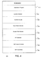
- FIG. 7 a block diagram for one embodiment of the AP database 432 of FIGS. 4 and 6 is shown, in accordance with the present invention.
- the FIG. 7 embodiment is presented for purposes of illustration, and in alternate embodiments, AP database 432 may include components and functionalities in addition to, or instead of, certain of those components and functionalities discussed in conjunction with the FIG. 7 embodiment.
- AP database 432 includes, but is not limited to, a series of entries 740 that each corresponds to a different access point 130 in the WiFi network.
- each entry 740 includes, but is not limited to, an AP identifier that specifically identifies a corresponding one of the access points 130.
- Each AP identifier is associated with corresponding AP coordinates that indicate a physical location for the particular access point 130.
- the AP coordinates may include any desired location information, including but not limited to, a device latitude, a device longitude, and a device altitude.
- the population of AP database 432 is further discussed below in conjunction with FIGS. 8-9B .
- FIG. 8 a diagram illustrating an access point location procedure is shown, in accordance with one embodiment of the present invention.
- the FIC. 8 embodiment is presented for purposes of illustration, and in alternate embodiments, locating access points 130 may include techniques and functionalities in addition to, or instead of, certain of those techniques and functionalities discussed in conjunction with the FIG. 8 embodiment.
- the location of access point (AP) 130 is unknown.
- Three mobile devices 114 (D1 114(a), D2 114(b), and D3 114(c)), whose locations are known by utilizing any effective means, are located in relative proximity to access point 130.
- a single mobile device 114 may be utilized by simply moving the single device 114 to three (or more) different locations.
- a greater number of mobile devices 114 may also be utilized.
- device 114(a) scans for, and detects, a WiFi signal from access point 130.
- device 114(a) then records an AP identifier and a signal strength for the scanned access point 130 as WiFi scan data 440.
- Device 114(a) wirelessly transmits the WiFi scan data 440 to a location server 126 (see FIG. 1 ) or other appropriate entity.
- the location server 126 evaluates the signal strength from the received WiFi scan data 440 to create a location circle 818 with a radius R1 822 that represents the distance from device 114(a) to the scanned access point 130. In other words, the target access point 130 lies somewhere on location circle 818.
- device 114(b) similarly scans for, and detects, a WiFi signal from access point 130.
- device 114(b) then records an AP identifier and a signal strength for the scanned access point 130 as WiFi scan data 440.
- Device 114(b) wirelessly transmits the WiFi scan data 440 to location server 126 or other appropriate entity.
- the location server 126 evaluates the signal strength from the received WiFi scan data 440 to create a location circle 824 with a radius R2 828 that represents the distance from device 114(b) to the scanned access point 130. In other words, the target access point 130 lies somewhere on location circle 824.
- device 114(c) also scans for, and detects, a WiFi signal from access point 130.
- device 114(c) then records an AP identifier and a signal strength for the scanned access point 130 as WiFi scan data 440.
- Device l14(c) wirelessly transmits the WiFi scan data 440 to location server 126 or other appropriate entity.
- the location server 126 evaluates the signal strength from the received WiFi scan data 440 to create a location circle 832 with a radius R3 836 that represents the distance from device 114(c) to the scanned access point 130. In other words, the target access point 130 lies somewhere on location circle 832.
- an AP location calculator 626 may then evaluate all the received WiFi scan data 440 from the three mobile devices 114 to determine a specific location for access point 130 by utilizing any effective calculation techniques.
- the location of access point 130 may be defined as the point at which all three location circles 818, 824, and 832 intersect, or as the only point that may be triangulated by utilizing the three radius vectors 822, 824, and 836.
- location server 126 may utilize that location information to update the AP database 432, as discussed above. Additional techniques for updating AP database 432 are discussed below in conjunction with FIG. 9 .
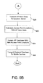
- FIGS. 9A-9B a flowchart of method steps for efficiently populating an access point database is shown, in accordance with one embodiment of the present invention.
- the example of FIGS. 9A-9B is presented for purposes of illustration, and in alternate embodiments, the present invention may utilize steps and sequences other than those step and sequences discussed in conjunction with the embodiment of FIGS. 9A-9B .
- step 912 mobile devices 114 in an electronic network initially determine their physical location by utilizing any appropriate techniques.
- the mobile devices 114 may receive transmitted signals from a global positioning system (GPS), and in step 914, the mobiles devices 114 may utilize the corresponding GPS signals to determine their respective physical locations.
- the mobile devices 114 each transmit their particular location coordinates to a location server 126 in the electronic network.
- GPS global positioning system
- the mobile devices 114 automatically perform a wireless scanning procedure to detect and store any appropriate AP scan data 440 from access point signals transmitted from one or more access points 130 that are distributed throughout the electronic network.
- the captured AP scan data 440 may include, but is not limited to, access point identifiers and access point signal strengths corresponding to respective access points 130.
- the FIG. 9A process then advances to step 920 of FIG. 9B through connecting letter "A.”
- step 920 the mobile devices 114 transmit the captured AP scan data 440 to the location server 126 by utilizing any appropriate techniques.
- an AP location calculator 626 of the location server 126 utilizes the received AP scan data 440 to perform an access point location procedure.
- AP location calculator 626 utilizes the received AP scan data 440 to calculate specific access point locations for one or more access points 130 in the electronic network by utilizing any appropriate and effective location calculation techniques.
- step 924 the location server 126 updates an access point database 432 with any new or different access point locations that are discovered as a result of the foregoing access point location procedure.
- step 926 the location server 126 transmits the updated access point database 432 to the mobile devices 114 for use in calculating physical locations of the respective mobile devices 114 with respect to the access points 130.
- the present invention thus provides an improved system and method for efficiently populating an access point database.
Abstract
Description
- This invention relates generally to a system and method for efficiently populating an access point database.
- Implementing effective methods for utilizing mobile electronic devices is a significant consideration for designers and manufacturers of contemporary electronic devices. However, effectively implementing mobile devices may create substantial challenges for system designers. For example, enhanced demands for increased system functionality and performance may require more device processing power and require additional device resources. An increase in processing or device requirements may also result in a corresponding detrimental economic impact due to increased production costs and operational inefficiencies.
- Furthermore, enhanced device capability to perform various advanced operations may provide additional benefits to a device user, but may also place increased demands on the control and management of various device components. For example, implementing an enhanced electronic device that effectively provides accurate device-location information to a device user may present certain difficulties because of the unpredictable operating environments that may potentially be encountered.
- Due to growing demands on system resources and the significant difficulty in predicting the varying device operating conditions and environments, it is apparent that developing new techniques for implementing and utilizing mobile electronic devices is a matter of concern for related electronic technologies. Therefore, for all the foregoing reasons, developing effective systems for implementing and utilizing mobile electronic devices remains a significant consideration for designers, manufacturers, and users of contemporary electronic devices.
- In accordance with the present invention, a system and method are disclosed for efficiently populating an access point database. In accordance with one embodiment of the present invention, mobile devices in an electronic network initially determine their physical location by utilizing any appropriate techniques. For example, the mobile devices may receive transmitted signals from a global positioning system (GPS), and may then utilize the corresponding GPS signals to determine their respective physical locations. The mobile devices each transmit their particular location coordinates to a location server in the electronic network.
- In accordance with the present invention, the mobile devices automatically perform a wireless scanning procedure to detect and store any appropriate access point scan data from access point signals transmitted from one or more access points that are distributed throughout the electronic network. The captured access point scan data may include, but is not limited to, access point identifiers and access point signal strengths corresponding to respective access points. The mobile devices then transmit the captured access point scan data to the location server by utilizing any appropriate techniques.
- An access point location calculator of the location server utilizes the received access point scan data to perform an access point location procedure. In particular, the access point location calculator utilizes the received access point scan data to calculate specific access point locations for one or more access points in the electronic network by utilizing any appropriate and effective location calculation techniques.
- The location server then updates the access point database with any new or different access point locations that are discovered as a result of the foregoing access point location procedure. Finally, the location server may transmit the updated access point database to the mobile devices for use in calculating physical locations of the respective mobile devices with respect to the access points. For at least the foregoing reasons, the present invention therefore provides an improved system and method for efficiently populating an access point database.
- Preferably, the invention relates to techniques for utilizing mobile electronic devices.
- Various respective aspects and features of the invention are defined in the appended claim, Combinations of featured from the dependent claims may be combined with features of the independent claims as appropriate and not merely as explicitly set out in the claims.
- Embodiments of the invention will now be described with reference to the accompanying drawings, throughout which like parts are referred to by like references, and in which:
-
FIG. 1 is a block diagram of an electronic system, in accordance with one embodiment of the present invention; -
FIG. 2 is a block diagram for one embodiment of an access point ofFIG. 1 , in accordance with the present invention; -
FIG. 3 is a block diagram for one embodiment of a mobile device ofFIG. 1 , in accordance with the present invention; -
FIG. 4 is a block diagram for one embodiment of the MD memory ofFIG. 3 , in accordance with the present invention; -
FIG. 5 is one embodiment for one embodiment of the location server ofFIG. 1 , in accordance with the present invention; -
FIG. 6 is a block diagram for one embodiment of the server memory ofFIG. 5 , in accordance with the present invention; -
FIG. 7 is a block diagram for one embodiment of the AP database ofFIGS. 4 and6 , in accordance with the present invention; -
FIG. 8 is a diagram illustrating an access point location procedure, in accordance with one embodiment of the present invention; and -
FIGS. 9A-9B present a flowchart of method steps for efficiently populating an access point database, in accordance with one embodiment of the present invention. - The present invention relates to an improvement in the effective utilization of mobile electronic devices. The following description is presented to enable one of ordinary skill in the art to make and use the invention, and is provided in the context of a patent application and its requirements. Various modifications to the disclosed embodiments will be readily apparent to those skilled in the art, and the generic principles herein may be applied to other embodiments. Thus, the present invention is not intended to be limited to the embodiments shown, but is to be accorded the widest scope consistent with the principles and features described herein.
- The present invention is described herein as a system and method for populating an access point database, and includes a network of access points that are implemented to transmit access point signals by utilizing a wireless broadcasting procedure. One or more mobile devices are then configured to wirelessly receive and analyze the access point signals to produce access point scan data corresponding to the access points. A location server receives and analyzes the access point scan data to determine specific access point locations for the access points. The location server may then utilize the calculated access point locations to populate the access point database.
- Referring now to
FIG. 1 , a block diagram of anelectronic system 110 is shown, in accordance with one embodiment of the present invention. In theFIG. 1 embodiment,electronic system 110 may include, but is not limited to, one or more mobile device(s) 114, a plurality ofsatellites 118, a plurality ofbase stations 122, alocation server 126, and a plurality ofaccess points 130. In alternate embodiments,electronic system 110 may be implemented using various components and configurations in addition to, or instead of, those components and configurations discussed in conjunction with theFIG. 1 embodiment. - For purposes of illustration, the
FIG. 1 embodiment is implemented with one or more mobile device(s) 114, foursatellites 118, twobase stations 122, onelocation server 126, and threeaccess points 130. However, in various other embodiments,electronic network 110 may be implemented to include any desired number of themobile devices 114,satellites 118,base stations 122,location servers 126, andaccess points 130. - In the
FIG. 1 embodiment, mobile device(s) 114 may be implemented as any type of electronic device for which a current physical location may be determined and conveyed to a device user or other appropriate entity. For example, in certain embodiments,mobile devices 114 may include, but are not limited to, a laptop computer device, a personal digital assistant (PDA), or a cellular telephone. Additional details regarding the implementation and utilization ofmobile device 114 are further discussed below in conjunction withFIGS. 3-4 . - In the
FIG. 1 embodiment,satellites 130 include, but are not limited to, a satellite A 118(a), a satellite B 118(b), a satellite C 118(c), and a satellite D 118(d) that are implemented by utilizing any appropriate technologies to perform any desired functions or operations. For example, in certain embodiments,satellites 118 may be implemented as part of a known or enhanced global positioning system (GPS). In theFIG. 1 embodiment,satellites 118 typically transmit respective satellite beacon signals thatmobile devices 114 may receive and analyze using known location calculation procedures (such as trilateralization and/or triangulation) to potentially determine current physical locations (such as longitude, latitude, and altitude information) formobile devices 114. - However, in certain situations,
mobile devices 114 may be unable to receive satellite beacon signals from a sufficient number of thesatellites 130 to successfully perform the location calculation procedures. For example,mobile devices 114 may be inside a building or other structure that prevents some or all of the satellite beacon signals from reaching mobile devices 1 14. Or one or more of the satellites beacon signals may have insufficient signal quality characteristics. To provide additional signal sources from locations other thansatellites 130, theFIG. 1 embodiment may include a base station A 122(a) and a base station B 122(b) that are both implemented as terrestrial devices that transmit pilot signals that may be received bymobile devices 114. As with the foregoing satellite beacon signals,mobile devices 114 may analyze the pilot signals frombase stations 122 using similar location calculation procedures potentially determine the current physical locations ofmobile devices 114. - In the
FIG. 1 embodiment,base stations 122 may be implemented by utilizing any appropriate technologies to perform any desired functions or operations. For example, in certain embodiments,base stations 122 may be implemented as part of a known or enhanced wireless wide-area network (WWAN) system by utilizing any appropriate technologies. Furthermore, in certain embodiments,satellites 118 andbase stations 122 may be implemented as part of a known or enhanced assisted global-positioning system (AGPS) network. In certain embodiments,electronic network 110 may also include alocation server 126 thatmobile devices 114 utilize to perform various types of calculations or processing functions to thereby conserve processing resources formobile devices 114. - However, in certain operating environments,
mobile devices 114 may still be unable to receive a satisfactory combination of satellite beacon signals from thesatellites 130 and pilot signals from thebase stations 122 to successfully perform the location calculation procedures to accurately locatemobile device 114. For example,mobile devices 114 may be inside a concrete parking structure or a shopping mall that prevents some or all of the satellite beacon signals and pilot signals from reachingmobile device 114. Or one or more of the satellite beacon signals or base station pilot signals may have insufficient signal quality characteristics (signal strength, signal-to-noise ratios, etc.). - In accordance with the present invention, in order to provide additional beacon signals from signal sources other than
satellites 130 andbase stations 122, theFIG. 1 embodiment advantageously includesaccess points 130 that are implemented as terrestrial devices that transmit access-point beacon signals tomobile devices 114. As with the previously-discussed satellite beacon signals and pilot signals,mobile devices 114 may also analyze the access-point beacon signals using similar location calculation procedures to more accurately and effectively determine the current physical location ofmobile devices 114. - In the
FIG. 1 embodiment,access points 130 include, but are not limited to, an access point A 130(a), an access point B 130(b), and an access point C 130(c) that may be implemented by utilizing any appropriate technologies to perform any desired functions or operations. For example, in certain embodiments,access points 130 may be implemented as part of a known or enhanced wireless local-area network (WLAN) system using any appropriate technologies. In certain embodiments,access points 130 may be implemented according to WLAN standards that include, but are not limited to, any of the known 802.11 WLAN standards (such as 802.11a. 802.11b, 802.11g, and 802.11n). - In certain embodiments in which
access points 130 are implemented as publicly-deployed WiFi "hotspots" or other similar WLAN nades/systems, the widespread presence of such WLAN networks provides a ready availability of pre-existingpotential access points 130 at many public locations. However, in order to successfully utilizeaccess points 130 to accurately locatemobile devices 114, an access point (AP) database (seeFIG. 7 ) is typically utilized to specifically indicate physical coordinates for eachaccess point 130. - Because access points 130 have easily changeable locations, and because access points 130 may be added or removed at any time, one traditional method of populating and maintaining a AP database is to employ one or more individuals to drive around an area with a WiFi scanner device to measure and physically locate any available access points 130. This process is time-consuming and expensive. In addition, any resulting AP database may be inaccurate because of changes that have occurred since the last scanning process.
- The present invention therefore proposes to advantageously utilize WiFi functionality of the
mobile devices 114 to automatically and transparently scan on an ongoing basis for access point signals transmitted from the access points 130. Themobile devices 114 may then automatically transmit the AP measurement data tolocation server 126 or another appropriate entity for populating and updating the AP database. Additional details regarding the efficient updating of an access point database are further discussed below in conjunction withFIGS. 3-9B . - Referring now to
FIG. 2 , a block diagram for one embodiment of aFIG. 1 access point 130 is shown, in accordance with the present invention. In theFIG. 2 embodiment,access point 130 may include, but is not limited to, an AP central processing unit (CPU) 212, anAP transceiver 214, anAP display 216, anAP memory 220, and one or more AP input/output interfaces (I/O interfaces) 224. Selected ones of the foregoing components ofaccess point 130 may be coupled to, and communicate through, anAP bus 228. In alternate embodiments,access point 130 may be implemented using various components and configurations in addition to, or instead of, certain of components and configurations discussed in conjunction with theFIG. 2 embodiment. - In the
FIG. 2 embodiment,AP CPU 212 may be implemented to include any appropriate and compatible microprocessor device that preferably executes software instructions to thereby control and manage the operation ofaccess point 130. In theFIG. 2 embodiment,AP memory 220 may be implemented to include any combination of desired storage devices, including, but not limited to, read--only memory (ROM), random-access memory (RAM), and various types of non-volatile memory, such as floppy disks, flash memory, or hard disks. In theFIG. 2 embodiment, AP I/O interfaces 224 may preferably include one or more input and/or output interfaces to receive and/or transmit any required types of information foraccess point 130. For example, in theFIG. 2 embodiment,access point 130 may utilize AP I/O interfaces 224 to bi-directionally communicate with any desired type of external entities to receive or send electronic information by utilizing any appropriate and effective techniques. - In the
FIG. 2 embodiment,access point 130 may utilizeAP display 216 for displaying any desired type of information by utilizing any effective type of display technologies. In theFIG. 2 embodiment,AP transceiver 214 may include any appropriate means for bi-directionally transferring (transmitting and/or receiving) electronic information betweenaccess point 130 and other devices by utilizing wireless communication techniques. For example,access point 130 may utilizeAP transceiver 214 to transmit any desired type of access-point beacon signals tomobile devices 114, as discussed above in conjunction withFIG. 1 . - In the
FIG. 2 embodiment,AP transceiver 214 may generate certain types of enhanced access-point beacon signals that include an enhanced acquisition code thatmobile device 114 may then analyze to identify aparticular access point 130, and to evaluate signal quality characteristics for thatparticular access point 130. The signal quality characteristics may include, but are not limited to signal strength characteristics. Additional details regarding the implementation and utilization ofaccess point 130 are further discussed below in conjunction withFIGS. 3-9B . - Referring now to
FIG. 3 , a block diagram for one embodiment of aFIG. 1 mobile device 114 is shown, in accordance with the present invention. In theFIG. 3 embodiment,mobile device 114 may include, but is not limited to, an MD central processing unit (CPU) 312, anMD transceiver 314, anMD display 316, anMD memory 320, and one or more MD input/output interfaces (I/O interfaces) 324. Selected ones of the foregoing components ofmobile device 114 may be coupled to, and communicate through, anMD bus 328. In alternate embodiments,mobile device 114 may be implemented using components and configurations in addition to, or instead of, certain of those components and configurations discussed in conjunction with theFIG. 3 embodiment. - In the
FIG. 3 embodiment,MD CPU 312 may be implemented to include any appropriate and compatible microprocessor device that preferably executes software instructions to thereby control and manage the operation ofmobile device 114. In theFIG. 3 embodiment,MD memory 320 may be implemented to include any combination of desired storage devices, including, but not limited to, read-only memory (ROM), random-access memory (RAM), and various types of non-volatile memory, such as floppy disks, flash memory, or hard disks. Additional details regarding the implementation and utilization ofMD memory 320 are further discussed below in conjunction withFIG. 4 . - In the
FIG. 3 embodiment, MD I/O interfaces 324 may preferably include one or more input and/or output interfaces to receive and/or transmit any required types of information formobile device 114. For example, in theFIG. 3 embodiment,mobile device 114 may utilize MD I/O interfaces 324 to bi-directionally communicate with any desired type of external entities to receive or send electronic information by utilizing any appropriate and effective techniques. In theFIG. 3 embodiment,mobile device 114 may utilizeMD display 316 for displaying any desired type of information by utilizing any effective type of display technologies. - In the
FIG. 3 embodiment,MD transceiver 314 may include any appropriate means for bi-directionally transferring (transmitting and/or receiving) electronic information betweenmobile device 114 and other devices by utilizing wireless communication techniques. In certain embodiments,MD transceiver 314 may include, but is not limited to, a satellite transceiver for communicating withsatellites 118, a base station transceiver for communicating withbase stations 126, and an access-point transceiver for communicating withaccess points 130. Additional details regarding the implementation and utilization ofmobile device 114 are further discussed below in conjunction withFIGS. 4-9B . - Referring now to
FIG. 4 , a block diagram for one embodiment of theFIG. 3 MD memory 320 is shown, in accordance with the present invention. In theFIG. 4 embodiment,MD memory 320 includes, but is not limited to, anapplication program 412, alocation detector 416, asatellite module 420, abase station module 424, anaccess point module 428, an access point (AP)database 432, aWiFi scan controller 436, andWiFi scan data 440. In alternate embodiments,MD memory 320 may include components and functionalities in addition to, or instead of, certain of those components and functionalities discussed in conjunction with theFIG. 4 embodiment. - In the
FIG. 4 embodiment,application program 412 may include program instructions that are preferably executed by MD CPU 312 (FIG. 3 ) to perform various functions and operations formobile device 114. The particular nature and functionality ofapplication program 412 typically varies depending upon factors such as the specific type and particular functionality of the correspondingmobile device 114. - In the
FIG. 4 embodiment,location detector 412 may be utilized to coordinate and manage enhanced mobile-device location procedures to determine a current physical location of amobile device 114 by utilizing any effective techniques. For example, in certain embodiments,location detector 412 may utilize information inAP database 432 to perform device location procedures. In certain embodiments, location server 126 (FIG. 1 ) may also have a software module similar tolocation detector 412 to remotely perform certain required processing functions. In theFIG. 4 embodiment,satellite module 424 may be utilized to manage communications with satellites 118 (FIG. 1 ). Similarly,base station module 424 may be utilized to manage communications with base stations 122 (FIG. 1 ), andaccess point module 428 may be utilized to manage communications with access points 130 (FIG. 1 ). - In the
FIG. 4 embodiment, aWiFi scan controller 436 automatically performs access point (AP) scanning procedures to measure relevant characteristics of transmissions from one or more access points 130. WiFi scan controller then stores any collected information asWiFi scan data 440. In theFIG. 4 embodiment,WiFi scan data 440 may include any types of measurement, data, or other information relating to respective ones of the access points 130 (FIG. 1 ). Examples of such information include, but are not limited to, presence/availability of access-point beacon signals, signal strengths, signal-to-noise values, signal quality characteristics, signal delays, etc. - In the
FIG. 4 embodiment, thelocation detector 416,WiFi scan controller 436, and thevarious modules FIGS. 5-9B . - Referring now to
FIG. 5 , a block diagram for theFIG. 1 location server 126 is shown, in accordance with one embodiment of the present invention. In theFIG. 5 embodiment, location server 125 includes, but is not limited to, aserver CPU 514, aserver memory 518, aserver display 538, and I/O interface(s) 540. In alternate embodiments,location server 126 may be implemented using components and configurations in addition to, or instead of, certain of those components and configurations discussed in conjunction with theFIG. 5 embodiment. - In the
FIG. 5 embodiment,server CPU 514 may be implemented to include any appropriate and compatible microprocessor device that preferably executes software instructions to thereby control and manage the operation oflocation server 126. In theFIG. 5 embodiment,server memory 518 may be implemented to include any combination of desired storage devices, including, but not limited to, read-only memory (ROM), random-access memory (RAM), and various types of non-volatile memory, such as floppy disks, flash memory, or hard disks. Additional details regarding the implementation and utilization ofserver memory 518 are further discussed below if conjunction withFIG. 6 . - In the
FIG. 5 embodiment, I/O interfaces 540 may preferably include one or more input and/or output interfaces to receive and/or transmit any required types of information forlocation server 126. For example, in theFIG. 5 embodiment,location server 126 may utilize I/O interfaces 540 to bi-directionally communicate with any desired type of external entities to receive or send electronic information by utilizing any appropriate and effective techniques. In theFIG. 5 embodiment,location server 126 may utilizeserver display 538 for displaying any desired type of information by utilizing any effective type of display technologies. Additional details regarding the implementation and utilization oflocation server 126 are further discussed below in conjunction withFIGS. 6-9B . - Referring now to
FIG. 6 , a block diagram for one embodiment of theFIG. 5 server memory 518 is shown, in accordance with the present invention. In theFIG. 5 embodiment,server memory 518 includes, but is not limited to, aserver application 622, anAP location calculator 626,WiFi scan data 440, anAP database 432, acommunication module 638, andmiscellaneous information 654. In alternate embodiments,server memory 518 may include components and functionalities in addition to, or instead of, certain of those components and functionalities discussed in conjunction with theFIG. 6 embodiment. - In the
FIG. 6 embodiment,server application 622 may include program instructions that are preferably executed by server CPU 514 (FIG. 5 ) to perform various functions and operations forlocation server 126. The particular nature and functionality ofserver application 622 typically varies depending upon factors such as the specific type and particular functionality of the correspondinglocation server 126. - In the
FIG. 6 embodiment,location server 126 usesAP location calculator 626 to analyze appropriate information fromWiFi scan data 440 to determine specific locations for one or more access points 130 (FIG. 1 ) in any effective manner. For example,AP location calculator 626 may utilizeWiFi scan data 440 to calculated location coordinates for a givenaccess point 130 by performing basic triangulation calculations, as discussed below in conjunction withFIG. 8 . In other embodiments, more complex calculation techniques may be utilized to build statistical models that represent the location of one ormore access points 130 by utilizing a greater number of AP measurements frommobile devices 114. - In the
FIG. 6 embodiment,AP location calculator 626 may populate and updateAP database 432 with newly calculated locations of one or more access points 130. One embodiment forAP database 432 is further discussed below in conjunction withFIG. 7 .Location server 126 may utilizecommunication module 638 to conduct bi-directional communications with any external entity, including but not limited to,mobile devices 114.Miscellaneous information 654 may include any other information or data for use bylocation server 126. The utilization oflocation server 126 is further discussed below in conjunction withFIGS. 7-9B . - Referring now to
FIG. 7 , a block diagram for one embodiment of theAP database 432 ofFIGS. 4 and6 is shown, in accordance with the present invention. TheFIG. 7 embodiment is presented for purposes of illustration, and in alternate embodiments,AP database 432 may include components and functionalities in addition to, or instead of, certain of those components and functionalities discussed in conjunction with theFIG. 7 embodiment. - In the
FIG. 7 embodiment,AP database 432 includes, but is not limited to, a series ofentries 740 that each corresponds to adifferent access point 130 in the WiFi network. In theFIG. 7 embodiment, eachentry 740 includes, but is not limited to, an AP identifier that specifically identifies a corresponding one of the access points 130. Each AP identifier is associated with corresponding AP coordinates that indicate a physical location for theparticular access point 130. The AP coordinates may include any desired location information, including but not limited to, a device latitude, a device longitude, and a device altitude. The population ofAP database 432 is further discussed below in conjunction withFIGS. 8-9B . - Referring now to
FIG. 8 , a diagram illustrating an access point location procedure is shown, in accordance with one embodiment of the present invention. The FIC. 8 embodiment is presented for purposes of illustration, and in alternate embodiments, locatingaccess points 130 may include techniques and functionalities in addition to, or instead of, certain of those techniques and functionalities discussed in conjunction with theFIG. 8 embodiment. - In the
FIG. 8 example, the location of access point (AP) 130 is unknown. Three mobile devices 114 (D1 114(a), D2 114(b), and D3 114(c)), whose locations are known by utilizing any effective means, are located in relative proximity to accesspoint 130. In an alternate embodiment, a singlemobile device 114 may be utilized by simply moving thesingle device 114 to three (or more) different locations. In alternate embodiment, a greater number ofmobile devices 114 may also be utilized. - In accordance with the present invention, device 114(a) scans for, and detects, a WiFi signal from
access point 130. In theFIG. 8 embodiment, device 114(a) then records an AP identifier and a signal strength for the scannedaccess point 130 asWiFi scan data 440. Device 114(a) wirelessly transmits theWiFi scan data 440 to a location server 126 (seeFIG. 1 ) or other appropriate entity. Thelocation server 126 evaluates the signal strength from the receivedWiFi scan data 440 to create alocation circle 818 with aradius R1 822 that represents the distance from device 114(a) to the scannedaccess point 130. In other words, thetarget access point 130 lies somewhere onlocation circle 818. - In the
FIG. 8 example, device 114(b) similarly scans for, and detects, a WiFi signal fromaccess point 130. In theFIG. 8 embodiment, device 114(b) then records an AP identifier and a signal strength for the scannedaccess point 130 asWiFi scan data 440. Device 114(b) wirelessly transmits theWiFi scan data 440 tolocation server 126 or other appropriate entity. Thelocation server 126 evaluates the signal strength from the receivedWiFi scan data 440 to create alocation circle 824 with aradius R2 828 that represents the distance from device 114(b) to the scannedaccess point 130. In other words, thetarget access point 130 lies somewhere onlocation circle 824. - In the
FIG. 8 example, device 114(c) also scans for, and detects, a WiFi signal fromaccess point 130. In theFIG. 8 embodiment, device 114(c) then records an AP identifier and a signal strength for the scannedaccess point 130 asWiFi scan data 440. Device l14(c) wirelessly transmits theWiFi scan data 440 tolocation server 126 or other appropriate entity. Thelocation server 126 evaluates the signal strength from the receivedWiFi scan data 440 to create alocation circle 832 with aradius R3 836 that represents the distance from device 114(c) to the scannedaccess point 130. In other words, thetarget access point 130 lies somewhere onlocation circle 832. - In accordance with the
FIG. 8 embodiment, anAP location calculator 626 may then evaluate all the receivedWiFi scan data 440 from the threemobile devices 114 to determine a specific location foraccess point 130 by utilizing any effective calculation techniques. For example, in theFIG. 8 example, the location ofaccess point 130 may be defined as the point at which all threelocation circles radius vectors access point 130 are know,location server 126 may utilize that location information to update theAP database 432, as discussed above. Additional techniques for updatingAP database 432 are discussed below in conjunction withFIG. 9 . - Referring now to
FIGS. 9A-9B , a flowchart of method steps for efficiently populating an access point database is shown, in accordance with one embodiment of the present invention. The example ofFIGS. 9A-9B is presented for purposes of illustration, and in alternate embodiments, the present invention may utilize steps and sequences other than those step and sequences discussed in conjunction with the embodiment ofFIGS. 9A-9B . - In the
FIG. 9A embodiment, instep 912,mobile devices 114 in an electronic network initially determine their physical location by utilizing any appropriate techniques. For example, instep 912, themobile devices 114 may receive transmitted signals from a global positioning system (GPS), and instep 914, themobiles devices 114 may utilize the corresponding GPS signals to determine their respective physical locations. Instep 916, themobile devices 114 each transmit their particular location coordinates to alocation server 126 in the electronic network. - In
step 918, themobile devices 114 automatically perform a wireless scanning procedure to detect and store any appropriateAP scan data 440 from access point signals transmitted from one ormore access points 130 that are distributed throughout the electronic network. The capturedAP scan data 440 may include, but is not limited to, access point identifiers and access point signal strengths corresponding to respective access points 130. TheFIG. 9A process then advances to step 920 ofFIG. 9B through connecting letter "A." - In
step 920, themobile devices 114 transmit the capturedAP scan data 440 to thelocation server 126 by utilizing any appropriate techniques. Instep 922, anAP location calculator 626 of thelocation server 126 utilizes the receivedAP scan data 440 to perform an access point location procedure. In particular,AP location calculator 626 utilizes the receivedAP scan data 440 to calculate specific access point locations for one ormore access points 130 in the electronic network by utilizing any appropriate and effective location calculation techniques. - In
step 924, thelocation server 126 updates anaccess point database 432 with any new or different access point locations that are discovered as a result of the foregoing access point location procedure. Finally, instep 926, thelocation server 126 transmits the updatedaccess point database 432 to themobile devices 114 for use in calculating physical locations of the respectivemobile devices 114 with respect to the access points 130. The present invention thus provides an improved system and method for efficiently populating an access point database. - The invention has been explained above with reference to certain embodiments. Other embodiments will be apparent to those skilled in the art in light of this disclosure. For example, the present invention may readily be implemented using configurations and techniques other than those described in the embodiments above. Additionally, the present invention may effectively be used in conjunction with systems other than those described above. Therefore, these and other variations upon the discussed embodiments are intended to be covered by the present invention, which is limited only by the appended claims.
Claims (15)
- A system for populating an access point database, comprising:access points that are configured to transmit access point signals by utilizing a wireless broadcasting procedure;mobile devices that wirelessly receive and analyze said access point signals to produce access point scan data corresponding to said access points; anda location server that receives said access point scan data, said location server analyzing said access point scan data to determine access point locations of said access points, said location server utilizing said access point locations to populate said access point database.
- The system of claim 1 wherein said access point database is utilized by said mobile devices to perform device location procedures with reference to said access point locations in said access point database.
- The system of claim 1 wherein said access points are implemented as WiFi hotspots in a wireless electronic network.
- The system of claim 1 wherein said access point scan data includes access points identifiers and access point signal strengths for said access points.
- The system of claim 1 wherein said mobile devices automatically produce said access point scan data without assistance from device users.
- The system of claim 1 wherein said location server determines said access point locations by performing triangulation procedures that are based upon said access point scan data.
- The system of claim 1 wherein physical locations of said mobile devices are determined by utilizing wireless transmission techniques from a global positioning system, said mobile devices transmitting said physical locations to said location server, said mobile devices automatically and continuously scanning said access point signals to produce and store said access point scan data, said location server gradually building a statistical model of said access point locations from said access point scan data, said location server utilizing said access point locations from said statistical model to populate and update said access point database.
- An electronic device for utilizing an access point database, comprising:a software program that wirelessly receives and analyzes access point signals transmitted from access points to produce access point scan data corresponding to said access points, said access point data being transmitted to a location server that analyzing said access point scan data to determine access point locations of said access points, said location server utilizing said access point locations to populate said access point database; anda processor that executes said software program on said electronic device.
- The electronic device of claim 8 wherein said access point database is utilized by said electronic device to perform device location procedures with reference to said access point locations in said access point database.
- The electronic device of claim 8 wherein said access points are implemented as WiFi hotspots in a wireless electronic network.
- The electronic device of claim 8 wherein said access point scan data includes access points identifiers and access point signal strengths for said access points.
- The electronic device of claim 52 wherein, said electronic device automatically produces said access point scan data without assistance from a device user.
- The electronic device of claim 8 wherein said location server determines said access point locations by performing triangulation procedures that are based upon said access point scan data.
- The electronic device of claim 8 wherein physical locations of said electronic device is determined by utilizing wireless transmission techniques from a global positioning system, said electronic device transmitting said physical locations to said location server, said electronic device automatically and continuously scanning said access point signals to produce and store said access point scan data, said location server gradually building a statistical model of said access point locations from said access point scan data, said location server utilizing said access point locations from said statistical model to populate and update said access point database.
- A method for populating an access point database, comprising:transmitting access point signals from access points by utilizing a wireless broadcasting procedure;utilizing mobile devices to wirelessly receive and analyze said access point signals to produce access point scan data corresponding to said access points; andreceiving said access point scan data with a location server that analyzes said access point scan data to determine access point locations of said access points, said location server utilizing said access point locations to populate said access point database.
Applications Claiming Priority (1)
| Application Number | Priority Date | Filing Date | Title |
|---|---|---|---|
| US12/378,314 US20100208711A1 (en) | 2009-02-13 | 2009-02-13 | System and method for efficiently populating an access point database |
Publications (3)
| Publication Number | Publication Date |
|---|---|
| EP2219401A2 true EP2219401A2 (en) | 2010-08-18 |
| EP2219401A3 EP2219401A3 (en) | 2011-12-21 |
| EP2219401B1 EP2219401B1 (en) | 2017-10-25 |
Family
ID=42104396
Family Applications (1)
| Application Number | Title | Priority Date | Filing Date |
|---|---|---|---|
| EP10151910.6A Not-in-force EP2219401B1 (en) | 2009-02-13 | 2010-01-28 | System and method for efficiently populating an access point database |
Country Status (6)
| Country | Link |
|---|---|
| US (1) | US20100208711A1 (en) |
| EP (1) | EP2219401B1 (en) |
| CN (1) | CN101808400A (en) |
| BR (1) | BRPI1000318B1 (en) |
| RU (1) | RU2503149C2 (en) |
| TW (1) | TW201044897A (en) |
Cited By (4)
| Publication number | Priority date | Publication date | Assignee | Title |
|---|---|---|---|---|
| US20120249373A1 (en) * | 2011-01-17 | 2012-10-04 | Qualcomm Incorporated | Populating Non-Positional Transmitter Location Databases Using Information about Recognized Positional Transmitters |
| WO2013176998A3 (en) * | 2012-05-21 | 2014-03-20 | Qualcomm Incorporated | Method and apparatus for determining locations of access points |
| GB2508255A (en) * | 2012-09-07 | 2014-05-28 | Cambridge Silicon Radio Ltd | Determining Locations of a Plurality of Radio Frequency Signal Sources |
| US9121922B2 (en) | 2012-06-26 | 2015-09-01 | Cambridge Silicon Radio Limited | Access point location identification methods and apparatus based on absolute and relative harvesting |
Families Citing this family (14)
| Publication number | Priority date | Publication date | Assignee | Title |
|---|---|---|---|---|
| US7966384B2 (en) * | 2008-08-04 | 2011-06-21 | Flat Hill Ideas, Llc | Real-time interactive system and method for making and updating changes to infrastructure data |
| US8744352B2 (en) * | 2010-11-22 | 2014-06-03 | Juniper Networks, Inc. | Automatic access point location, planning, and coverage optimization |
| CN102622947A (en) * | 2011-01-30 | 2012-08-01 | 郑建民 | Automobile wheel advertisement sticker |
| US8676227B2 (en) * | 2011-05-23 | 2014-03-18 | Transcend Information, Inc. | Method of performing a data transaction between a portable storage device and an electronic device |
| CN102802258A (en) * | 2011-05-27 | 2012-11-28 | 北京百度网讯科技有限公司 | Method, server and system for extending locating database |
| US8670425B1 (en) * | 2011-08-09 | 2014-03-11 | Sprint Spectrum L.P. | Use of past duration of stay as trigger to scan for wireless coverage |
| US9113310B2 (en) | 2013-05-21 | 2015-08-18 | Intel Corporation | Systems and methods for simultaneously and automatically creating databases of wifi signal information |
| KR102109585B1 (en) | 2013-06-19 | 2020-05-13 | 삼성전자주식회사 | Method for implementing location based service, machine-readable storage medium, server and electronic device |
| CN105934685B (en) * | 2014-03-03 | 2018-11-02 | 英特尔Ip公司 | Access point position determination is carried out by mobile device crowdsourcing |
| CN104918323A (en) * | 2014-03-12 | 2015-09-16 | 电信科学技术研究院 | Terminal location method and device |
| CN106211321B (en) * | 2016-07-28 | 2018-03-30 | 上海掌门科技有限公司 | For the method and apparatus for the positional information for determining user equipment |
| CN106501797A (en) * | 2016-11-18 | 2017-03-15 | 武汉博思创信息科技有限公司 | A kind of method of the coordinate position for determining each LED |
| US10547977B2 (en) * | 2017-10-26 | 2020-01-28 | Qualcomm Incorporated | Method and apparatus for crowdsourcing the location of mobile terrestrial transports |
| US20200067767A1 (en) * | 2018-08-23 | 2020-02-27 | Hewlett Packard Enterprise Development Lp | Automated provisioning of networked access points by port or location |
Family Cites Families (15)
| Publication number | Priority date | Publication date | Assignee | Title |
|---|---|---|---|---|
| US6898434B2 (en) * | 2001-10-30 | 2005-05-24 | Hewlett-Packard Development Company, L.P. | Apparatus and method for the automatic positioning of information access points |
| US6973384B2 (en) * | 2001-12-06 | 2005-12-06 | Bellsouth Intellectual Property Corporation | Automated location-intelligent traffic notification service systems and methods |
| US7127257B2 (en) * | 2001-12-27 | 2006-10-24 | Qualcomm Incorporated | Use of mobile stations for determination of base station location parameters in a wireless mobile communication system |
| US7319878B2 (en) * | 2004-06-18 | 2008-01-15 | Qualcomm Incorporated | Method and apparatus for determining location of a base station using a plurality of mobile stations in a wireless mobile network |
| US7403762B2 (en) * | 2004-10-29 | 2008-07-22 | Skyhook Wireless, Inc. | Method and system for building a location beacon database |
| KR101249178B1 (en) * | 2005-02-22 | 2013-04-03 | 스카이후크 와이어리스, 인크. | Continuous data optimization in positioning system |
| TW200718241A (en) * | 2005-06-24 | 2007-05-01 | Qualcomm Inc | Apparatus and method for determining WLAN access point position |
| US8589532B2 (en) * | 2005-06-24 | 2013-11-19 | Qualcomm Incorporated | Apparatus and method for determining WLAN access point position |
| CN101346638A (en) * | 2005-11-07 | 2009-01-14 | 高通股份有限公司 | Positioning for WLANs and other wireless networks |
| CN106054129A (en) * | 2005-11-07 | 2016-10-26 | 高通股份有限公司 | Positioning for wlans and other wireless networks |
| US7466986B2 (en) * | 2006-01-19 | 2008-12-16 | International Business Machines Corporation | On-device mapping of WIFI hotspots via direct connection of WIFI-enabled and GPS-enabled mobile devices |
| US20070184845A1 (en) * | 2006-02-09 | 2007-08-09 | Troncoso Edmund R | Providing geographic context for applications and services on a wide area network |
| US7907579B2 (en) * | 2006-08-15 | 2011-03-15 | Cisco Technology, Inc. | WiFi geolocation from carrier-managed system geolocation of a dual mode device |
| US8811349B2 (en) * | 2007-02-21 | 2014-08-19 | Qualcomm Incorporated | Wireless node search procedure |
| US20080242310A1 (en) * | 2007-03-27 | 2008-10-02 | Qualcomm Incorporated | Method and apparatus for determining location of access point |
-
2009
- 2009-02-13 US US12/378,314 patent/US20100208711A1/en not_active Abandoned
-
2010
- 2010-01-28 EP EP10151910.6A patent/EP2219401B1/en not_active Not-in-force
- 2010-02-01 TW TW099102845A patent/TW201044897A/en unknown
- 2010-02-05 RU RU2010103949/07A patent/RU2503149C2/en active
- 2010-02-05 BR BRPI1000318-5A patent/BRPI1000318B1/en not_active IP Right Cessation
- 2010-02-11 CN CN201010116156A patent/CN101808400A/en active Pending
Non-Patent Citations (1)
| Title |
|---|
| None |
Cited By (8)
| Publication number | Priority date | Publication date | Assignee | Title |
|---|---|---|---|---|
| US20120249373A1 (en) * | 2011-01-17 | 2012-10-04 | Qualcomm Incorporated | Populating Non-Positional Transmitter Location Databases Using Information about Recognized Positional Transmitters |
| WO2013176998A3 (en) * | 2012-05-21 | 2014-03-20 | Qualcomm Incorporated | Method and apparatus for determining locations of access points |
| JP2015525340A (en) * | 2012-05-21 | 2015-09-03 | クゥアルコム・インコーポレイテッドQualcomm Incorporated | Method and apparatus for determining the location of an access point |
| US9432964B2 (en) | 2012-05-21 | 2016-08-30 | Qualcomm Incorporated | Method and apparatus for determining locations of access points |
| US9121922B2 (en) | 2012-06-26 | 2015-09-01 | Cambridge Silicon Radio Limited | Access point location identification methods and apparatus based on absolute and relative harvesting |
| GB2508255A (en) * | 2012-09-07 | 2014-05-28 | Cambridge Silicon Radio Ltd | Determining Locations of a Plurality of Radio Frequency Signal Sources |
| US8909258B2 (en) | 2012-09-07 | 2014-12-09 | Cambridge Silicon Radio Limited | Context and map aiding for self-learning |
| US9194933B2 (en) | 2012-09-07 | 2015-11-24 | Qualcomm Technologies International, Ltd. | Context and map aiding for self-learning |
Also Published As
| Publication number | Publication date |
|---|---|
| CN101808400A (en) | 2010-08-18 |
| RU2503149C2 (en) | 2013-12-27 |
| RU2010103949A (en) | 2011-08-10 |
| EP2219401A3 (en) | 2011-12-21 |
| BRPI1000318A2 (en) | 2011-07-26 |
| TW201044897A (en) | 2010-12-16 |
| US20100208711A1 (en) | 2010-08-19 |
| EP2219401B1 (en) | 2017-10-25 |
| BRPI1000318B1 (en) | 2021-02-02 |
Similar Documents
| Publication | Publication Date | Title |
|---|---|---|
| EP2219401B1 (en) | System and method for efficiently populating an access point database | |
| US8792387B2 (en) | System and method for effectively populating a mesh network model | |
| US8310397B2 (en) | System and method for effectively performing enhanced mobile-device location procedures | |
| CN104620125B (en) | Method and apparatus for calculating location of terminal in wireless communication system | |
| EP3227706B1 (en) | Supporting radio model quality assurance | |
| JP5087105B2 (en) | Positioning apparatus and method | |
| EP3234627B1 (en) | Checking the health of radio model data | |
| EP3271739B1 (en) | Enabling a validation of an estimated position of a mobile device | |
| US10841742B2 (en) | Supporting a configuration of a device | |
| EP1450179A1 (en) | Test apparatus and control method for a wireless communication network | |
| WO2008112347A1 (en) | Determining location information | |
| CN105425263A (en) | Providing wireless transmitter almanac information to mobile station based on expected contribution to future navigation operation | |
| WO2013173361A1 (en) | Outdoor position estimation of a mobile device within a vicinity of one or more indoor environments | |
| EP3754303A1 (en) | Floor levels of a venue | |
| JP2017500589A (en) | Method and apparatus for delivering assistance data from a server to a device identifying a virtual access point | |
| Huber | Background Positioning for Mobile devices-Android vs. iphone | |
| CN106538001A (en) | Cooperative locating method and wireless terminal | |
| EP2965116B1 (en) | Synchronous network device time transfer for location determination | |
| EP2653881A1 (en) | Cooperative localization of portable electronic devices | |
| TW201140123A (en) | Locating electromagnetic signal sources | |
| KR101684630B1 (en) | System and method for providing portable beacon service using mobile device | |
| KR20120010014A (en) | Positioning Database Constructing System, Apparatus for Analyzing pCell Database and Method therefor |
Legal Events
| Date | Code | Title | Description |
|---|---|---|---|
| PUAI | Public reference made under article 153(3) epc to a published international application that has entered the european phase |
Free format text: ORIGINAL CODE: 0009012 |
|
| AK | Designated contracting states |
Kind code of ref document: A2 Designated state(s): AT BE BG CH CY CZ DE DK EE ES FI FR GB GR HR HU IE IS IT LI LT LU LV MC MK MT NL NO PL PT RO SE SI SK SM TR |
|
| AX | Request for extension of the european patent |
Extension state: AL BA RS |
|
| RIN1 | Information on inventor provided before grant (corrected) |
Inventor name: GEORGIS, NIKOLAOS Inventor name: ZHOU, YI Inventor name: CARPIO, FREDRIK |
|
| REG | Reference to a national code |
Ref country code: DE Ref legal event code: R079 Ref document number: 602010046139 Country of ref document: DE Free format text: PREVIOUS MAIN CLASS: H04W0024080000 Ipc: H04W0064000000 |
|
| PUAL | Search report despatched |
Free format text: ORIGINAL CODE: 0009013 |
|
| AK | Designated contracting states |
Kind code of ref document: A3 Designated state(s): AT BE BG CH CY CZ DE DK EE ES FI FR GB GR HR HU IE IS IT LI LT LU LV MC MK MT NL NO PL PT RO SE SI SK SM TR |
|
| AX | Request for extension of the european patent |
Extension state: AL BA RS |
|
| RIC1 | Information provided on ipc code assigned before grant |
Ipc: H04W 64/00 20090101AFI20111114BHEP |
|
| 17P | Request for examination filed |
Effective date: 20120608 |
|
| GRAP | Despatch of communication of intention to grant a patent |
Free format text: ORIGINAL CODE: EPIDOSNIGR1 |
|
| STAA | Information on the status of an ep patent application or granted ep patent |
Free format text: STATUS: GRANT OF PATENT IS INTENDED |
|
| INTG | Intention to grant announced |
Effective date: 20170516 |
|
| GRAS | Grant fee paid |
Free format text: ORIGINAL CODE: EPIDOSNIGR3 |
|
| GRAA | (expected) grant |
Free format text: ORIGINAL CODE: 0009210 |
|
| STAA | Information on the status of an ep patent application or granted ep patent |
Free format text: STATUS: THE PATENT HAS BEEN GRANTED |
|
| AK | Designated contracting states |
Kind code of ref document: B1 Designated state(s): AT BE BG CH CY CZ DE DK EE ES FI FR GB GR HR HU IE IS IT LI LT LU LV MC MK MT NL NO PL PT RO SE SI SK SM TR |
|
| REG | Reference to a national code |
Ref country code: GB Ref legal event code: FG4D |
|
| REG | Reference to a national code |
Ref country code: CH Ref legal event code: EP |
|
| REG | Reference to a national code |
Ref country code: AT Ref legal event code: REF Ref document number: 941014 Country of ref document: AT Kind code of ref document: T Effective date: 20171115 |
|
| REG | Reference to a national code |
Ref country code: IE Ref legal event code: FG4D |
|
| REG | Reference to a national code |
Ref country code: DE Ref legal event code: R096 Ref document number: 602010046139 Country of ref document: DE |
|
| REG | Reference to a national code |
Ref country code: FR Ref legal event code: PLFP Year of fee payment: 9 |
|
| REG | Reference to a national code |
Ref country code: NL Ref legal event code: MP Effective date: 20171025 |
|
| REG | Reference to a national code |
Ref country code: LT Ref legal event code: MG4D |
|
| REG | Reference to a national code |
Ref country code: AT Ref legal event code: MK05 Ref document number: 941014 Country of ref document: AT Kind code of ref document: T Effective date: 20171025 |
|
| PG25 | Lapsed in a contracting state [announced via postgrant information from national office to epo] |
Ref country code: NL Free format text: LAPSE BECAUSE OF FAILURE TO SUBMIT A TRANSLATION OF THE DESCRIPTION OR TO PAY THE FEE WITHIN THE PRESCRIBED TIME-LIMIT Effective date: 20171025 |
|
| PG25 | Lapsed in a contracting state [announced via postgrant information from national office to epo] |
Ref country code: NO Free format text: LAPSE BECAUSE OF FAILURE TO SUBMIT A TRANSLATION OF THE DESCRIPTION OR TO PAY THE FEE WITHIN THE PRESCRIBED TIME-LIMIT Effective date: 20180125 Ref country code: FI Free format text: LAPSE BECAUSE OF FAILURE TO SUBMIT A TRANSLATION OF THE DESCRIPTION OR TO PAY THE FEE WITHIN THE PRESCRIBED TIME-LIMIT Effective date: 20171025 Ref country code: LT Free format text: LAPSE BECAUSE OF FAILURE TO SUBMIT A TRANSLATION OF THE DESCRIPTION OR TO PAY THE FEE WITHIN THE PRESCRIBED TIME-LIMIT Effective date: 20171025 Ref country code: ES Free format text: LAPSE BECAUSE OF FAILURE TO SUBMIT A TRANSLATION OF THE DESCRIPTION OR TO PAY THE FEE WITHIN THE PRESCRIBED TIME-LIMIT Effective date: 20171025 Ref country code: SE Free format text: LAPSE BECAUSE OF FAILURE TO SUBMIT A TRANSLATION OF THE DESCRIPTION OR TO PAY THE FEE WITHIN THE PRESCRIBED TIME-LIMIT Effective date: 20171025 |
|
| PG25 | Lapsed in a contracting state [announced via postgrant information from national office to epo] |
Ref country code: BG Free format text: LAPSE BECAUSE OF FAILURE TO SUBMIT A TRANSLATION OF THE DESCRIPTION OR TO PAY THE FEE WITHIN THE PRESCRIBED TIME-LIMIT Effective date: 20180125 Ref country code: GR Free format text: LAPSE BECAUSE OF FAILURE TO SUBMIT A TRANSLATION OF THE DESCRIPTION OR TO PAY THE FEE WITHIN THE PRESCRIBED TIME-LIMIT Effective date: 20180126 Ref country code: LV Free format text: LAPSE BECAUSE OF FAILURE TO SUBMIT A TRANSLATION OF THE DESCRIPTION OR TO PAY THE FEE WITHIN THE PRESCRIBED TIME-LIMIT Effective date: 20171025 Ref country code: IS Free format text: LAPSE BECAUSE OF FAILURE TO SUBMIT A TRANSLATION OF THE DESCRIPTION OR TO PAY THE FEE WITHIN THE PRESCRIBED TIME-LIMIT Effective date: 20180225 Ref country code: PT Free format text: LAPSE BECAUSE OF FAILURE TO SUBMIT A TRANSLATION OF THE DESCRIPTION OR TO PAY THE FEE WITHIN THE PRESCRIBED TIME-LIMIT Effective date: 20180226 Ref country code: HR Free format text: LAPSE BECAUSE OF FAILURE TO SUBMIT A TRANSLATION OF THE DESCRIPTION OR TO PAY THE FEE WITHIN THE PRESCRIBED TIME-LIMIT Effective date: 20171025 Ref country code: AT Free format text: LAPSE BECAUSE OF FAILURE TO SUBMIT A TRANSLATION OF THE DESCRIPTION OR TO PAY THE FEE WITHIN THE PRESCRIBED TIME-LIMIT Effective date: 20171025 |
|
| REG | Reference to a national code |
Ref country code: DE Ref legal event code: R097 Ref document number: 602010046139 Country of ref document: DE |
|
| PG25 | Lapsed in a contracting state [announced via postgrant information from national office to epo] |
Ref country code: CZ Free format text: LAPSE BECAUSE OF FAILURE TO SUBMIT A TRANSLATION OF THE DESCRIPTION OR TO PAY THE FEE WITHIN THE PRESCRIBED TIME-LIMIT Effective date: 20171025 Ref country code: CY Free format text: LAPSE BECAUSE OF FAILURE TO SUBMIT A TRANSLATION OF THE DESCRIPTION OR TO PAY THE FEE WITHIN THE PRESCRIBED TIME-LIMIT Effective date: 20171025 Ref country code: EE Free format text: LAPSE BECAUSE OF FAILURE TO SUBMIT A TRANSLATION OF THE DESCRIPTION OR TO PAY THE FEE WITHIN THE PRESCRIBED TIME-LIMIT Effective date: 20171025 Ref country code: DK Free format text: LAPSE BECAUSE OF FAILURE TO SUBMIT A TRANSLATION OF THE DESCRIPTION OR TO PAY THE FEE WITHIN THE PRESCRIBED TIME-LIMIT Effective date: 20171025 Ref country code: SK Free format text: LAPSE BECAUSE OF FAILURE TO SUBMIT A TRANSLATION OF THE DESCRIPTION OR TO PAY THE FEE WITHIN THE PRESCRIBED TIME-LIMIT Effective date: 20171025 |
|
| PG25 | Lapsed in a contracting state [announced via postgrant information from national office to epo] |
Ref country code: IT Free format text: LAPSE BECAUSE OF FAILURE TO SUBMIT A TRANSLATION OF THE DESCRIPTION OR TO PAY THE FEE WITHIN THE PRESCRIBED TIME-LIMIT Effective date: 20171025 Ref country code: RO Free format text: LAPSE BECAUSE OF FAILURE TO SUBMIT A TRANSLATION OF THE DESCRIPTION OR TO PAY THE FEE WITHIN THE PRESCRIBED TIME-LIMIT Effective date: 20171025 Ref country code: SM Free format text: LAPSE BECAUSE OF FAILURE TO SUBMIT A TRANSLATION OF THE DESCRIPTION OR TO PAY THE FEE WITHIN THE PRESCRIBED TIME-LIMIT Effective date: 20171025 Ref country code: PL Free format text: LAPSE BECAUSE OF FAILURE TO SUBMIT A TRANSLATION OF THE DESCRIPTION OR TO PAY THE FEE WITHIN THE PRESCRIBED TIME-LIMIT Effective date: 20171025 |
|
| PLBE | No opposition filed within time limit |
Free format text: ORIGINAL CODE: 0009261 |
|
| REG | Reference to a national code |
Ref country code: CH Ref legal event code: PL |
|
| STAA | Information on the status of an ep patent application or granted ep patent |
Free format text: STATUS: NO OPPOSITION FILED WITHIN TIME LIMIT |
|
| 26N | No opposition filed |
Effective date: 20180726 |
|
| PG25 | Lapsed in a contracting state [announced via postgrant information from national office to epo] |
Ref country code: LU Free format text: LAPSE BECAUSE OF NON-PAYMENT OF DUE FEES Effective date: 20180128 |
|
| REG | Reference to a national code |
Ref country code: IE Ref legal event code: MM4A |
|
| REG | Reference to a national code |
Ref country code: BE Ref legal event code: MM Effective date: 20180131 |
|
| PG25 | Lapsed in a contracting state [announced via postgrant information from national office to epo] |
Ref country code: LI Free format text: LAPSE BECAUSE OF NON-PAYMENT OF DUE FEES Effective date: 20180131 Ref country code: CH Free format text: LAPSE BECAUSE OF NON-PAYMENT OF DUE FEES Effective date: 20180131 Ref country code: SI Free format text: LAPSE BECAUSE OF FAILURE TO SUBMIT A TRANSLATION OF THE DESCRIPTION OR TO PAY THE FEE WITHIN THE PRESCRIBED TIME-LIMIT Effective date: 20171025 Ref country code: BE Free format text: LAPSE BECAUSE OF NON-PAYMENT OF DUE FEES Effective date: 20180131 |
|
| PG25 | Lapsed in a contracting state [announced via postgrant information from national office to epo] |
Ref country code: IE Free format text: LAPSE BECAUSE OF NON-PAYMENT OF DUE FEES Effective date: 20180128 |
|
| PG25 | Lapsed in a contracting state [announced via postgrant information from national office to epo] |
Ref country code: MC Free format text: LAPSE BECAUSE OF FAILURE TO SUBMIT A TRANSLATION OF THE DESCRIPTION OR TO PAY THE FEE WITHIN THE PRESCRIBED TIME-LIMIT Effective date: 20171025 |
|
| PG25 | Lapsed in a contracting state [announced via postgrant information from national office to epo] |
Ref country code: MT Free format text: LAPSE BECAUSE OF NON-PAYMENT OF DUE FEES Effective date: 20180128 |
|
| PG25 | Lapsed in a contracting state [announced via postgrant information from national office to epo] |
Ref country code: TR Free format text: LAPSE BECAUSE OF FAILURE TO SUBMIT A TRANSLATION OF THE DESCRIPTION OR TO PAY THE FEE WITHIN THE PRESCRIBED TIME-LIMIT Effective date: 20171025 |
|
| PG25 | Lapsed in a contracting state [announced via postgrant information from national office to epo] |
Ref country code: HU Free format text: LAPSE BECAUSE OF FAILURE TO SUBMIT A TRANSLATION OF THE DESCRIPTION OR TO PAY THE FEE WITHIN THE PRESCRIBED TIME-LIMIT; INVALID AB INITIO Effective date: 20100128 |
|
| PG25 | Lapsed in a contracting state [announced via postgrant information from national office to epo] |
Ref country code: MK Free format text: LAPSE BECAUSE OF NON-PAYMENT OF DUE FEES Effective date: 20171025 |
|
| PGFP | Annual fee paid to national office [announced via postgrant information from national office to epo] |
Ref country code: FR Payment date: 20201217 Year of fee payment: 12 Ref country code: GB Payment date: 20201218 Year of fee payment: 12 |
|
| PGFP | Annual fee paid to national office [announced via postgrant information from national office to epo] |
Ref country code: DE Payment date: 20201217 Year of fee payment: 12 |
|
| REG | Reference to a national code |
Ref country code: DE Ref legal event code: R119 Ref document number: 602010046139 Country of ref document: DE |
|
| GBPC | Gb: european patent ceased through non-payment of renewal fee |
Effective date: 20220128 |
|
| PG25 | Lapsed in a contracting state [announced via postgrant information from national office to epo] |
Ref country code: GB Free format text: LAPSE BECAUSE OF NON-PAYMENT OF DUE FEES Effective date: 20220128 Ref country code: DE Free format text: LAPSE BECAUSE OF NON-PAYMENT OF DUE FEES Effective date: 20220802 |
|
| PG25 | Lapsed in a contracting state [announced via postgrant information from national office to epo] |
Ref country code: FR Free format text: LAPSE BECAUSE OF NON-PAYMENT OF DUE FEES Effective date: 20220131 |