EP2268079A1 - Identifying a base station from a set of handover candidate base stations that use the same primary scrambling code - Google Patents
Identifying a base station from a set of handover candidate base stations that use the same primary scrambling code Download PDFInfo
- Publication number
- EP2268079A1 EP2268079A1 EP09290337A EP09290337A EP2268079A1 EP 2268079 A1 EP2268079 A1 EP 2268079A1 EP 09290337 A EP09290337 A EP 09290337A EP 09290337 A EP09290337 A EP 09290337A EP 2268079 A1 EP2268079 A1 EP 2268079A1
- Authority
- EP
- European Patent Office
- Prior art keywords
- base station
- handover
- femtocell
- base stations
- primary scrambling
- Prior art date
- Legal status (The legal status is an assumption and is not a legal conclusion. Google has not performed a legal analysis and makes no representation as to the accuracy of the status listed.)
- Granted
Links
- 238000000034 method Methods 0.000 claims abstract description 18
- 238000005259 measurement Methods 0.000 claims description 21
- 230000015654 memory Effects 0.000 claims description 5
- 101001076732 Homo sapiens RNA-binding protein 27 Proteins 0.000 description 19
- 102100025873 RNA-binding protein 27 Human genes 0.000 description 19
- 101100353523 Homo sapiens PSMA2 gene Proteins 0.000 description 17
- 102100040364 Proteasome subunit alpha type-2 Human genes 0.000 description 17
- 101100532686 Schizosaccharomyces pombe (strain 972 / ATCC 24843) psc3 gene Proteins 0.000 description 17
- 101100521593 Homo sapiens PSMB1 gene Proteins 0.000 description 14
- 102100031566 Proteasome subunit beta type-1 Human genes 0.000 description 14
- 101100465393 Homo sapiens PSMA1 gene Proteins 0.000 description 13
- 102100036042 Proteasome subunit alpha type-1 Human genes 0.000 description 13
- 238000010586 diagram Methods 0.000 description 10
- 238000004891 communication Methods 0.000 description 9
- -1 PSC4 Proteins 0.000 description 4
- FGUUSXIOTUKUDN-IBGZPJMESA-N C1(=CC=CC=C1)N1C2=C(NC([C@H](C1)NC=1OC(=NN=1)C1=CC=CC=C1)=O)C=CC=C2 Chemical compound C1(=CC=CC=C1)N1C2=C(NC([C@H](C1)NC=1OC(=NN=1)C1=CC=CC=C1)=O)C=CC=C2 FGUUSXIOTUKUDN-IBGZPJMESA-N 0.000 description 2
- 238000013500 data storage Methods 0.000 description 2
- 230000000694 effects Effects 0.000 description 2
- GNFTZDOKVXKIBK-UHFFFAOYSA-N 3-(2-methoxyethoxy)benzohydrazide Chemical compound COCCOC1=CC=CC(C(=O)NN)=C1 GNFTZDOKVXKIBK-UHFFFAOYSA-N 0.000 description 1
- YTAHJIFKAKIKAV-XNMGPUDCSA-N [(1R)-3-morpholin-4-yl-1-phenylpropyl] N-[(3S)-2-oxo-5-phenyl-1,3-dihydro-1,4-benzodiazepin-3-yl]carbamate Chemical compound O=C1[C@H](N=C(C2=C(N1)C=CC=C2)C1=CC=CC=C1)NC(O[C@H](CCN1CCOCC1)C1=CC=CC=C1)=O YTAHJIFKAKIKAV-XNMGPUDCSA-N 0.000 description 1
- 230000001413 cellular effect Effects 0.000 description 1
- 230000001419 dependent effect Effects 0.000 description 1
- 238000005516 engineering process Methods 0.000 description 1
- 230000007774 longterm Effects 0.000 description 1
Images


Classifications
-
- H—ELECTRICITY
- H04—ELECTRIC COMMUNICATION TECHNIQUE
- H04W—WIRELESS COMMUNICATION NETWORKS
- H04W36/00—Hand-off or reselection arrangements
- H04W36/08—Reselecting an access point
-
- H—ELECTRICITY
- H04—ELECTRIC COMMUNICATION TECHNIQUE
- H04W—WIRELESS COMMUNICATION NETWORKS
- H04W16/00—Network planning, e.g. coverage or traffic planning tools; Network deployment, e.g. resource partitioning or cells structures
- H04W16/24—Cell structures
- H04W16/32—Hierarchical cell structures
-
- H—ELECTRICITY
- H04—ELECTRIC COMMUNICATION TECHNIQUE
- H04W—WIRELESS COMMUNICATION NETWORKS
- H04W84/00—Network topologies
- H04W84/02—Hierarchically pre-organised networks, e.g. paging networks, cellular networks, WLAN [Wireless Local Area Network] or WLL [Wireless Local Loop]
- H04W84/04—Large scale networks; Deep hierarchical networks
- H04W84/042—Public Land Mobile systems, e.g. cellular systems
- H04W84/045—Public Land Mobile systems, e.g. cellular systems using private Base Stations, e.g. femto Base Stations, home Node B
-
- H—ELECTRICITY
- H04—ELECTRIC COMMUNICATION TECHNIQUE
- H04W—WIRELESS COMMUNICATION NETWORKS
- H04W84/00—Network topologies
- H04W84/02—Hierarchically pre-organised networks, e.g. paging networks, cellular networks, WLAN [Wireless Local Area Network] or WLL [Wireless Local Loop]
- H04W84/10—Small scale networks; Flat hierarchical networks
- H04W84/105—PBS [Private Base Station] network
Definitions
- the present invention relates to telecommunications, in particular to wireless telecommunications.
- Wireless telecommunications systems are well-known. Many such systems are cellular, in that radio coverage is provided by a bundle of radio coverage areas known as cells. A base station that provides radio coverage is located in each cell. Traditional base stations provide coverage in relatively large geographic areas and the corresponding cells are often referred to as macrocells.
- femtocells Cells that are smaller than macrocells are sometimes referred to as microcells, picocells, or femtocells, but we use the term femtocells generically for cells that are smaller than macrocells.
- One way to establish a femtocell is to provide a femtocell base station that operates within a relatively limited range within the coverage area of a macrocell.
- One example of use of a femtocell base station is to provide wireless communication coverage within a building.
- the femtocell base station is of a relatively low transmit power and hence each femtocell is of a small coverage area compared to a macrocell.
- Femtocell base stations are intended primarily for users belonging to a particular home or office. Femtocell base stations may be private access or public access. In femtocell base stations that are private access, access is restricted only to registered users, for example family members or particular groups of employees. In femtocell base stations that are public access, other users may also use the femtocell base station, subject to certain restrictions to protect the Quality of Service received by registered users.
- One known type of Femtocell base station uses a broadband Internet Protocol connection as "backhaul”, namely for connecting to the core network.
- One type of broadband Internet Protocol connection is a Digital Subscriber Line (DSL).
- the DSL connects a DSL transmitter-receiver ("transceiver") of the femtocell base station to the core network.
- the DSL allows voice calls and other services provided via the femtocell base station to be supported.
- the femtocell base station also includes a radio frequency (RF) transceiver connected to an antenna for radio communications.
- RF radio frequency
- Femtocell base stations are sometimes referred to as femtos.
- PSCs primary scrambling codes
- a femto detects from received signals which PSCs are in use by other base stations around that femto, and selects a PSC that the femto has not detected as being in use, else it selects the PSC of the weakest signal received.
- each of the available primary scrambling codes is used by multiple femtos, in other words much primary scrambling code "re-use".
- user terminals currently in a cell, make measurements as to signals received from other nearby base stations and report these measurements to the base station of that cell. This is so as to determine whether it is appropriate to handover the call connection with the user terminal from that cell to another cell from which a stronger or better quality signal is received.
- a known approach is to seek to handover to all of the femtocells that are identified as using the primary scrambling code of the best received signal. This is inefficient because only one of the handover attempts is permitted to succeed. Network resources are wasted that are used in the handover attempts to the other femtocells than the one that is successful.
- femtocell base station To determine which of the neighbouring femtos using that PSC provides the best signal to the user terminal and so should be the handover target, a known approach is for the femtocell base station to cease to transmit and instead receive at the frequency that user terminals receive at, in order to detect neighbouring femtos. This is known as sniffing. This works in detecting neighbouring femtos that are strongly transmitting, but may not detect every femto that the user terminal would detect as a handover candidate.
- Femto2 and Femto3 are neighbours of Femto1.
- Femto2 and Femto3 both use the same primary scrambling code PSC1 whilst Femto 1 uses a different primary scrambling code PSC2.
- Femto2 and Femto3 both use the same primary scrambling code PSC1, when a user terminal UE connected to Femto1 moves towards Femto2, it will send a measurement report indicating that the target femto is that using PSC1. However this PSC is used by Femto3 also. Since Femto1 has previously "sniffed” and detected that both Femto2 & Femto3 use PSC 1, it does not know whether the UE is moving towards Femto2 or Femto3, and hence which one of those two should be the handover target.
- An example of the present invention is a method of identifying a base station, to which to handover a call connection with a user terminal, from a set of handover candidate base stations that use the same primary scrambling code.
- the method comprises comparing the primary scrambling codes of signals detected by the user terminal to those expected from each handover candidate base station and its respective neighbouring base stations. A match being found by the comparison identifies the base station for handover.
- Some preferred embodiments provide simple, effective target cell identification for handovers, particularly in Universal Mobile Telecommunications System (UMTS) networks. Efficient selection of the base station to handover to is useful on maintaining a high quality of service to user terminals.
- UMTS Universal Mobile Telecommunications System
- Some embodiments have the femtocell controller/gateway identify the target base station for handover. Some embodiments have the source base station for handover, such as a source femto, identify the target base station for handover.
- Preferred embodiments provide useful solutions when there is primary scrambling code reuse within a network.
- the use made of the information as to the PSCs of neighbours of candidate target base stations in identifying target base stations reduces the probability of dropped calls and wasted radio resources.
- a network 10 for wireless communications through which a user terminal 34 may roam, includes two types of base station, namely macrocell base stations and femtocell base stations (the latter being sometimes called "femtos").
- macrocell base stations are shown in Figures 2 and 3 for simplicity.
- Each macrocell base station has a radio coverage area 24 that is often referred to as a macrocell.
- the geographic extent of the macrocell 24 depends on the capabilities of the macrocell base station 22 and the surrounding geography.
- each femtocell base station 30 provides wireless communications within a corresponding femtocell 32.
- a femtocell is a radio coverage area.
- the radio coverage area of the femtocell 32 is much less than that of the macrocell 24.
- the femtocell 32 corresponds in size to a user's office or home.
- the network 10 is managed by a radio network controller, RNC, 170.
- the radio network controller, RNC, 170 controls the operation, for example by communicating with macrocell base stations 22 via a backhaul communications link 160.
- the radio network controller 170 maintains a neighbour list which includes information about the geographical relationship between cells supported by base stations.
- the radio network controller 170 maintains location information which provides information on the location of the user equipment within the wireless communications system 10.
- the radio network controller 170 is operable to route traffic via circuit-switched and packet-switched networks. For circuit-switched traffic, a mobile switching centre 250 is provided with which the radio network controller 170 may communicate.
- the mobile switching centre 250 communicates with a circuit-switched network such as a public switched telephone network (PSTN) 210.
- a circuit-switched network such as a public switched telephone network (PSTN) 210.
- PSTN public switched telephone network
- the network controller 170 communicates with serving general packet radio service support nodes (SGSNs) 220 and a gateway general packet radio support node (GGSN) 180.
- SGSNs general packet radio service support nodes
- GGSN gateway general packet radio support node
- the GGSN then communicates with a packet-switch core 190 such as, for example, the Internet.
- the MSC 250 , SGSN 220, GGSN 180 and operator IP network constitute a so-called core network 253.
- the SGSN 220 and GGSN 180 are connected by an operator IP network 215 to a femtocell controller/gateway 230.
- the femtocell controller/gateway 230 is connected via the Internet 190 to the femtocell base stations 30. These connections to the femtocell controller/gateway 230 are broadband Internet Protocol connections ("backhaul”) connections.
- backhaul broadband Internet Protocol connections
- a mobile terminal 34 within the macrocell 24 it is possible for a mobile terminal 34 within the macrocell 24 to communicate with the macrocell base station 22 in known manner.
- the mobile terminal 34 enters into a femtocell 32 for which the mobile terminal is registered for communications with the femtocell base station 30, it is desirable to handover the connection with the mobile terminal from the macrocell to the femtocell.
- the user of mobile terminal 34 is a preferred user of the nearest 32' of the femtocells 32.
- the femtocell base stations 30 are connected via the broadband Internet Protocol connections ("backhaul") 36 to the core network (not shown in Figure 3 ) and hence the rest of the telecommunications "world” (not shown in Figure 3 ).
- the "backhaul" connections 36 allow communications between the femtocell base stations 30 through the core network (not shown).
- the macrocell base station is also connected to the core network (not shown in Figure 3 ).
- the femtocell controller/gateway includes a processor 232 connected to a memory 234.
- Information 236 about the base stations in the network are stored in the memory 234; for convenience this information 236 is referred to as a topology map.
- Femto1 uses primary scrambling code PSC1 whilst Femto2 and Femto3, which are neighbours to Femto1 both use primary scrambling code PSC2.
- Femto2 also has neighbouring femtos: Femto4, Femto5 and Femto6.
- Femto4 and Femto6 both use PSC3.
- Femto5 uses PSC5.
- Femto3 also has neighbouring femtos: Femto7, Femto8 and Femto9.
- Femto7 and Femto9 both use PSC4.
- Femto8 uses PSC6. There is a user terminal UE moving within the macrocell.
- the user terminal 34 sends measurement reports via the macrocell base station 22 to which it is connected, to the Radio Network Controller 170.
- Each report includes data of the received signal strength and quality of signals received from various femtos together with the respective primary scrambling codes used.
- the measurement reports are of known type, for example 1A, 1B or 1C as defined in Third Generation Partnership Project (3GPP) Technical Specification TS25.331.
- the user terminal 34 sends (step a as shown in Figure 6 ) a measurement report that indicates that a femtocell is detected that provides a better quality connection than the current macrocell (“MacroCell1") and that femto uses PSC2.
- the measurement report provides signal quality information for signals having PSCs in a monitored set, namely PSC1, PSC2 , PSC3 and PSC5.
- the RNC 170 then sends (step b) a relocation request message to the core network 253.
- the core network 253 sends (step c) the relocation request on to the femtocell controller/gateway 230.
- This relocation request includes the UE Measurement Report, the primary scrambling code PSC2 of the femto, the primary scrambling code and unique cell identifier (Cell ID) of the macrocell, and a list of PSCs of the other cells that are in a monitored set detected by the user terminal 34.
- these primary scrambling codes are those of Femto1, Femto4, Femto5 and Femto6, namely PSC1, PSC3, and PSC5.
- the femtocell controller/gateway 230 uses the primary scrambling codes supplied together with the 'topology map', in other words the recorded information about neighbour relations between base stations, in order to identify the correct femto as the target for handover of the call connection with the user terminal 34. In this case, as between Femto2 and Femto3, both of which use PSC2, the target is identified as being Femto2.
- the femtocell controller/gateway 230 then forwards (step e) the relocation request to Femto2, which replies (step f) with a relocation request acknowledgement. This acknowledgement is received by the femtocell controller/gateway 230 and forwarded (step g) to the core network 253.
- the core network responds (step h) by sending a relocation command to the RNC 170.
- the RNC then sends (step i) a radio bearer reconfiguration message to the user terminal 34 so as to effect the handover to the identified femto, namely Femto2.
- the messages shown in Figure 6 are standardised in Universal Mobile Telecommunications System (UMTS).
- UMTS Universal Mobile Telecommunications System
- the handover procedure is then completed (step j) in a manner known to the skilled person in the art.
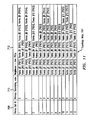
- the topology map used in this example is shown in Figure 7 .
- the topology map 700 consists of three sets of entries: namely Femtocell Identifiers 702, the primary scrambling codes that they use 704, and a third set 706 of neighbours and their primary scrambling codes.
- the gateway 230 uses (step 8a) the target cell PSC (PSC2 in this example) to identify handover candidates (Femto2 and Femto 3 in this example, both of which use PSC2). For each handover candidate, the gateway then uses (step 8b) the topology map to identify the neighbours of each handover candidate and the PSCs of those neighbours.
- the gateway uses (step 8b) the topology map to identify the neighbours of each handover candidate and the PSCs of those neighbours.
- neighbours Femto1(PSC1), Femto4(PSC3), Femto5(PSC5) and Femto6 (PSC3) are identified.
- Femto3 neighbours Femto 1(PSC1), Femto9(PSC4), Femto7 (PSC4) and Femto8 (PSC6).
- a query is then made (step 8c) as to whether the PSCs of the neighbours of the candidate match the PSCs of the neighbours of the candidate cell provided by the user terminal in the measurement report.
- the expected PSCs for Femto2's neighbours are PSC1, PSC3, and PSC5 and this agrees with the measurement report indicating those PSCs are detected in addition to the PSC of Femto2. Accordingly Femto2 is confirmed (step 8d) as the handover candidate.
- the expected PSCs for Femto3's neighbours are PSC1, PSC4, and PSC6 and this does not agree agrees with the measurement report indicating PSC1, PSC3 and PSC5 are detected in addition to the PSC2 of Femto2. Accordingly, Femto3 is discarded (step 8e) as a handover candidate.
- the PSCs of neighbouring femtocells that are monitored by the user terminal are used to aid identification of the target handover cell.
- Each femto includes a memory in which is stored information about its neighbouring base stations; for convenience this information is referred to as a topology map.
- Femto1 uses primary scrambling code PSC2, whilst Femto2 and Femto3, which are neighbours to Femto1 both use primary scrambling code PSC1.
- Femto 1 also has neighbour Femto5(using PSC3), Femto6(using PSC4), Femto 10 (using PSC3) and Femto 11 (using PSC5).
- Femto2, in addition to neighbours Femto1, Femto6 an Femto10 also has further neighbouring femtos: Femto7(using PSC6), Femto8 (using PSC5) and Femto9 (using PSC4).
- Femto3, in addition to neighbours Femto1, Femto5 and Femto11 also has further neighbouring femtos: Femto4(using PSC2), Femto 12 (using PSC3) and Femto13(using PSC4).
- the user terminal 34 sends measurement reports to the current ("source ”) femto to which the user terminal is connected, namely Femto I in this example.
- Each report includes data of the received signal strength and quality of signals received from various femtos together with the respective primary scrambling codes used.
- the measurement reports are of known type, for example 1A, 1B or 1C as defined in Third Generation Partnership Project (3GPP) Technical Specification TS25.331.
- the user terminal 34 sends (step a' as shown in Figure 10 ) a measurement report that indicates that a new femto is detected that provides a better quality connection than the current femto ("Femto 1") and that new femto uses PSC1.
- the measurement report provides signal quality information for signals using PSCs in a monitored set, namely PSC1, PSC3, PSC4 , PSC5 and PSC6. These are the PSCs of Femto2 and Femto6 through Femto 10.
- Femto1 uses (step b') the primary scrambling codes supplied together with the 'topology map', in other words the recorded information about neighbour relations between base stations, in order to identify the correct femto as the target for handover of the call connection with the user terminal 34.
- the target is identified as being Femto2.
- Femto1 then sends (step c') a handover request to Femto2, which replies (step d') with a handover request acknowledgement to Femto1.
- Femto1 then sends (step e') a radio bearer reconfiguration message to the user terminal 34 so as to effect the handover to the identified femto, namely Femto2.
- the handover procedure is then continued (step f) to completion.
- the topology map used in this example is shown in Figure 11 .
- the topology map 707 consists of three sets of entries, namely: Femtocell Identifiers 708, the primary scrambling codes that they use 710, and a third set 712 of neighbours and their primary scrambling codes.
- Femto1 uses (step 12a) the target cell PSC (PSC1 in this example) to identify handover candidates (Femto2 and Femto 3 in this example, both of which use PSC1).
- Femto1 uses (step 12b) the topology map to identify the neighbours (other than Femto1) of each handover candidate and the PSCs of those neighbours.
- neighbours Femto7(PSC6), Femto8(PSC5), Femto6 (PSC4), Femto 10(PSC3) and Femto9(PSC4) are expected.
- Femto3 neighbours are expected to be, Femto4 (PSC2), Femto13(PSC4), Femto12 (PSC3), Femto5(PSC3)and Femto 11 (PSC5).
- PSC2 Femto4
- PSC4 Femto13
- PSC3 Femto12
- PSC3 Femto5
- Femto 11 Femto 11
- a query is then made(step 12c) as to whether the expected PSCs of the neighbours of the candidate match the PSCs of the neighbours of the candidate cell provided by the user terminal in the measurement report.
- the expected PSCs for Femto2's neighbours are PSC3, PSC4, PSC5 and PSC6. This agrees with the measurement report indicating those PSCs are detected in addition to the PSC1 of Femto2. Accordingly Femto2 is confirmed (step 12d) as the handover candidate.
- the expected PSCs for Femto3's neighbours are PSC2, PSC3, PSC4, and PSC5 and this does not agree with the measurement report indicating primary scrambling codes of handover candidate neighbours of PSC3, PSC4 , PSC5 and PSC6, that are detected in addition to PSC1. Accordingly, Femto3 is discarded (step 12e) as a handover candidate.
- LTE Long Term Evolution
- CDMA Code Division Multiple Access
- program storage devices e.g., digital data storage media, which are machine or computer readable and encode machine-executable or computer-executable programs of instructions, wherein said instructions perform some or all of the steps of said above-described methods.
- the program storage devices may be, e.g., digital memories, magnetic storage media such as a magnetic disks and magnetic tapes, hard drives, or optically readable digital data storage media.
- Some embodiments involve computers programmed to perform said steps of the above-described methods.
Abstract
Description
- The present invention relates to telecommunications, in particular to wireless telecommunications.
- Wireless telecommunications systems are well-known. Many such systems are cellular, in that radio coverage is provided by a bundle of radio coverage areas known as cells. A base station that provides radio coverage is located in each cell. Traditional base stations provide coverage in relatively large geographic areas and the corresponding cells are often referred to as macrocells.
- It is possible to establish smaller sized cells within a macrocell. Cells that are smaller than macrocells are sometimes referred to as microcells, picocells, or femtocells, but we use the term femtocells generically for cells that are smaller than macrocells. One way to establish a femtocell is to provide a femtocell base station that operates within a relatively limited range within the coverage area of a macrocell. One example of use of a femtocell base station is to provide wireless communication coverage within a building.
- The femtocell base station is of a relatively low transmit power and hence each femtocell is of a small coverage area compared to a macrocell.
- Femtocell base stations are intended primarily for users belonging to a particular home or office. Femtocell base stations may be private access or public access. In femtocell base stations that are private access, access is restricted only to registered users, for example family members or particular groups of employees. In femtocell base stations that are public access, other users may also use the femtocell base station, subject to certain restrictions to protect the Quality of Service received by registered users.
- One known type of Femtocell base station uses a broadband Internet Protocol connection as "backhaul", namely for connecting to the core network. One type of broadband Internet Protocol connection is a Digital Subscriber Line (DSL). The DSL connects a DSL transmitter-receiver ("transceiver") of the femtocell base station to the core network. The DSL allows voice calls and other services provided via the femtocell base station to be supported. The femtocell base station also includes a radio frequency (RF) transceiver connected to an antenna for radio communications.
- Femtocell base stations are sometimes referred to as femtos.
- One problem of femtocell base stations, particularly those involving code division multiple access, such as those in accordance with current Third Generation Partnership Project (3GPP) Universal Mobile Telecommunications System (UMTS) standards, is that there are few primary scrambling codes (PSCs) available. Primary scrambling codes are broadcast by base stations over the radio interface and are used to distinguish between neighbouring base stations. Typically, there are between six and sixteen PSCs that are available to the femtocells. The PSC to be used by each femtocell base station is normally selected by an automatic configuration process based on measurements made by that femtocell base station. For example, a femto detects from received signals which PSCs are in use by other base stations around that femto, and selects a PSC that the femto has not detected as being in use, else it selects the PSC of the weakest signal received. In consequence typically each of the available primary scrambling codes is used by multiple femtos, in other words much primary scrambling code "re-use".
- As is known, user terminals, currently in a cell, make measurements as to signals received from other nearby base stations and report these measurements to the base station of that cell. This is so as to determine whether it is appropriate to handover the call connection with the user terminal from that cell to another cell from which a stronger or better quality signal is received.
- With this level of PSC reuse, there is a strong chance that user terminals served by a femto will detect signals from multiple different cells having the same primary scrambling code. There is no unique cell identifier, Cell ID, reported in the user terminal's measurement report according to current 3GPP standards. Accordingly, there is ambiguity or uncertainty as to which of the neighbouring femtos using that PSC provides the best signal to the user terminal and so should be the handover target.
- This problem in uniquely identifying which is the best femto target arises both in the case of macrocell to femtocell handovers and also in the case of femto to femto handovers.
- A known approach is to seek to handover to all of the femtocells that are identified as using the primary scrambling code of the best received signal. This is inefficient because only one of the handover attempts is permitted to succeed. Network resources are wasted that are used in the handover attempts to the other femtocells than the one that is successful.
- To determine which of the neighbouring femtos using that PSC provides the best signal to the user terminal and so should be the handover target, a known approach is for the femtocell base station to cease to transmit and instead receive at the frequency that user terminals receive at, in order to detect neighbouring femtos. This is known as sniffing. This works in detecting neighbouring femtos that are strongly transmitting, but may not detect every femto that the user terminal would detect as a handover candidate.
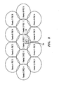
- As shown in
Figure 1 , the femtocells denoted Femto2 and Femto3 are neighbours of Femto1. Femto2 and Femto3 both use the same primary scrambling code PSC1 whilst Femto 1 uses a different primary scrambling code PSC2. - Because Femto2 and Femto3 both use the same primary scrambling code PSC1, when a user terminal UE connected to Femto1 moves towards Femto2, it will send a measurement report indicating that the target femto is that using PSC1. However this PSC is used by Femto3 also. Since Femto1 has previously "sniffed" and detected that both Femto2 & Femto3 use
PSC 1, it does not know whether the UE is moving towards Femto2 or Femto3, and hence which one of those two should be the handover target. - The reader is referred to the appended independent claims. Some preferred features are laid out in the dependent claims.
- An example of the present invention is a method of identifying a base station, to which to handover a call connection with a user terminal, from a set of handover candidate base stations that use the same primary scrambling code. The method comprises comparing the primary scrambling codes of signals detected by the user terminal to those expected from each handover candidate base station and its respective neighbouring base stations. A match being found by the comparison identifies the base station for handover.
- Some preferred embodiments provide simple, effective target cell identification for handovers, particularly in Universal Mobile Telecommunications System (UMTS) networks. Efficient selection of the base station to handover to is useful on maintaining a high quality of service to user terminals.
- Some embodiments have the femtocell controller/gateway identify the target base station for handover. Some embodiments have the source base station for handover, such as a source femto, identify the target base station for handover.
- Preferred embodiments provide useful solutions when there is primary scrambling code reuse within a network. In preferred embodiments, the use made of the information as to the PSCs of neighbours of candidate target base stations in identifying target base stations reduces the probability of dropped calls and wasted radio resources.
- Embodiments of the present invention will now be described by way of example and with reference to the drawings, in which:
-
Figure 1 is a diagram illustrating a known situation in identifying handover targets for a user terminal (PRIOR ART) -
Figure 2 is a diagram illustrating a wireless communications network according to a first embodiment of the present invention, -
Figure 3 is a diagram illustrating an example femtocell base station deployment within one macrocell shown inFigure 2 , -
Figure 4 is a diagram illustrating in more detail a femtocell controller/gateway as shown inFigure 2 , -
Figure 5 is a diagram illustrating the example femtocell deployment shown inFigure 3 in more detail, -
Figure 6 is a message sequence diagram in respect of a macrocell-to-femtocell handover operation in the deployment shown inFigure 5 , -
Figure 7 is a diagram illustration the topology map stored in the femtocell controller/gateway in respect of the femtocell deployment shown inFigure 5 , -
Figure 8 is a flowchart illustrating how, in the handover operation shown inFigure 7 , the topology map shown inFigure 6 is used to select the target femtocell, -
Figure 9 is a diagram illustrating an example femtocell deployment according to a second embodiment of the present invention, -
Figure 10 is a message sequence diagram in respect of a femtocell-to-femtocell handover operation in the femtocell deployment shown inFigure 9 , -
Figure 11 is a diagram illustration the topology map stored in the femtocell controller/gateway in respect of the femtocell deployment shown inFigure 9 , and -
Figure 12 is a flowchart illustrating how, in the handover operation shown inFigure 10 , the topology map shown inFigure 11 is used to select the target femtocell. - We now describe a network including femtocell base stations then look in greater detail at a femtocell base station and the relevant operation of the femtocell base station.
- As shown in
Figures 2 and3 , anetwork 10 for wireless communications, through which auser terminal 34 may roam, includes two types of base station, namely macrocell base stations and femtocell base stations (the latter being sometimes called "femtos"). Onemacrocell base station 22 is shown inFigures 2 and3 for simplicity. Each macrocell base station has aradio coverage area 24 that is often referred to as a macrocell. The geographic extent of themacrocell 24 depends on the capabilities of themacrocell base station 22 and the surrounding geography. - Within the
macrocell 24, eachfemtocell base station 30 provides wireless communications within a correspondingfemtocell 32. A femtocell is a radio coverage area. The radio coverage area of thefemtocell 32 is much less than that of themacrocell 24. For example, thefemtocell 32 corresponds in size to a user's office or home. - As shown in
Figure 2 , thenetwork 10 is managed by a radio network controller, RNC, 170. The radio network controller, RNC, 170 controls the operation, for example by communicating withmacrocell base stations 22 via a backhaul communications link 160. Theradio network controller 170 maintains a neighbour list which includes information about the geographical relationship between cells supported by base stations. In addition, theradio network controller 170 maintains location information which provides information on the location of the user equipment within thewireless communications system 10. Theradio network controller 170 is operable to route traffic via circuit-switched and packet-switched networks. For circuit-switched traffic, amobile switching centre 250 is provided with which theradio network controller 170 may communicate. Themobile switching centre 250 communicates with a circuit-switched network such as a public switched telephone network (PSTN) 210. For packet-switched traffic, thenetwork controller 170 communicates with serving general packet radio service support nodes (SGSNs) 220 and a gateway general packet radio support node (GGSN) 180. The GGSN then communicates with a packet-switch core 190 such as, for example, the Internet. - The
MSC 250 ,SGSN 220,GGSN 180 and operator IP network constitute a so-calledcore network 253. TheSGSN 220 andGGSN 180 are connected by anoperator IP network 215 to a femtocell controller/gateway 230. - The femtocell controller/
gateway 230 is connected via theInternet 190 to thefemtocell base stations 30. These connections to the femtocell controller/gateway 230 are broadband Internet Protocol connections ("backhaul") connections. - In
Figure 3 , threefemtocell base stations 30 andcorresponding femtocells 32 are shown for simplicity. - It is possible for a
mobile terminal 34 within themacrocell 24 to communicate with themacrocell base station 22 in known manner. When themobile terminal 34 enters into afemtocell 32 for which the mobile terminal is registered for communications with thefemtocell base station 30, it is desirable to handover the connection with the mobile terminal from the macrocell to the femtocell. In the example shown inFigure 3 , the user ofmobile terminal 34 is a preferred user of the nearest 32' of thefemtocells 32. - As shown in
Figure 3 , thefemtocell base stations 30 are connected via the broadband Internet Protocol connections ("backhaul") 36 to the core network (not shown inFigure 3 ) and hence the rest of the telecommunications "world" (not shown inFigure 3 ). The "backhaul"connections 36 allow communications between thefemtocell base stations 30 through the core network (not shown). The macrocell base station is also connected to the core network (not shown inFigure 3 ). - As shown in
Figure 4 , the femtocell controller/gateway includes aprocessor 232 connected to amemory 234.Information 236 about the base stations in the network are stored in thememory 234; for convenience thisinformation 236 is referred to as a topology map. - As shown in more detail in
Figure 5 , in this example, within the macrocell 24 (denoted Macrocell1) having a unique identifier CellID1 and a primary scrambling code denoted PSC100, nine femtos are shown. Of these nine, Femto1 uses primary scrambling code PSC1 whilst Femto2 and Femto3, which are neighbours to Femto1 both use primary scrambling code PSC2. Femto2 also has neighbouring femtos: Femto4, Femto5 and Femto6. Femto4 and Femto6 both use PSC3. Femto5 uses PSC5. Femto3 also has neighbouring femtos: Femto7, Femto8 and Femto9. Femto7 and Femto9 both use PSC4. Femto8 uses PSC6. There is a user terminal UE moving within the macrocell. - Referring to
Figure 6 , which is a Universal Mobile Telecommunications System (UMTS) example, theuser terminal 34 sends measurement reports via themacrocell base station 22 to which it is connected, to theRadio Network Controller 170. Each report includes data of the received signal strength and quality of signals received from various femtos together with the respective primary scrambling codes used. The measurement reports are of known type, for example 1A, 1B or 1C as defined in Third Generation Partnership Project (3GPP) Technical Specification TS25.331. In particular theuser terminal 34 sends (step a as shown inFigure 6 ) a measurement report that indicates that a femtocell is detected that provides a better quality connection than the current macrocell ("MacroCell1") and that femto uses PSC2. The measurement report provides signal quality information for signals having PSCs in a monitored set, namely PSC1, PSC2 , PSC3 and PSC5. - The
RNC 170 then sends (step b) a relocation request message to thecore network 253. Thecore network 253 sends (step c) the relocation request on to the femtocell controller/gateway 230. This relocation request includes the UE Measurement Report, the primary scrambling code PSC2 of the femto, the primary scrambling code and unique cell identifier (Cell ID) of the macrocell, and a list of PSCs of the other cells that are in a monitored set detected by theuser terminal 34. In this example, these primary scrambling codes are those of Femto1, Femto4, Femto5 and Femto6, namely PSC1, PSC3, and PSC5. - As a next step, the femtocell controller/
gateway 230 uses the primary scrambling codes supplied together with the 'topology map', in other words the recorded information about neighbour relations between base stations, in order to identify the correct femto as the target for handover of the call connection with theuser terminal 34. In this case, as between Femto2 and Femto3, both of which use PSC2, the target is identified as being Femto2. The femtocell controller/gateway 230 then forwards (step e) the relocation request to Femto2, which replies (step f) with a relocation request acknowledgement. This acknowledgement is received by the femtocell controller/gateway 230 and forwarded (step g) to thecore network 253. The core network responds (step h) by sending a relocation command to theRNC 170. The RNC then sends (step i) a radio bearer reconfiguration message to theuser terminal 34 so as to effect the handover to the identified femto, namely Femto2. - The messages shown in
Figure 6 are standardised in Universal Mobile Telecommunications System (UMTS). The handover procedure is then completed (step j) in a manner known to the skilled person in the art. - We shall now consider in more detail the topology map and its use.
- The topology map used in this example is shown in
Figure 7 . Thetopology map 700 consists of three sets of entries: namelyFemtocell Identifiers 702, the primary scrambling codes that they use 704, and athird set 706 of neighbours and their primary scrambling codes. - As shown in
Figure 8 , in this example, thegateway 230 uses (step 8a) the target cell PSC (PSC2 in this example) to identify handover candidates (Femto2 andFemto 3 in this example, both of which use PSC2). For each handover candidate, the gateway then uses (step 8b) the topology map to identify the neighbours of each handover candidate and the PSCs of those neighbours. In this example, for Femto2, neighbours Femto1(PSC1), Femto4(PSC3), Femto5(PSC5) and Femto6 (PSC3) are identified. For Femto3, neighbours Femto 1(PSC1), Femto9(PSC4), Femto7 (PSC4) and Femto8 (PSC6). - A query is then made (step 8c) as to whether the PSCs of the neighbours of the candidate match the PSCs of the neighbours of the candidate cell provided by the user terminal in the measurement report. In this example the expected PSCs for Femto2's neighbours are PSC1, PSC3, and PSC5 and this agrees with the measurement report indicating those PSCs are detected in addition to the PSC of Femto2. Accordingly Femto2 is confirmed (step 8d) as the handover candidate.
- Conversely, the expected PSCs for Femto3's neighbours are PSC1, PSC4, and PSC6 and this does not agree agrees with the measurement report indicating PSC1, PSC3 and PSC5 are detected in addition to the PSC2 of Femto2. Accordingly, Femto3 is discarded (
step 8e) as a handover candidate. - For femtocell to femtocell handovers, the PSCs of neighbouring femtocells that are monitored by the user terminal are used to aid identification of the target handover cell.
- Each femto includes a memory in which is stored information about its neighbouring base stations; for convenience this information is referred to as a topology map.
- As shown in
Figure 9 , in this example, thirteen femtos are shown. Of these thirteen, Femto1 uses primary scrambling code PSC2, whilst Femto2 and Femto3, which are neighbours to Femto1 both use primary scrambling code PSC1.Femto 1 also has neighbour Femto5(using PSC3), Femto6(using PSC4), Femto 10 (using PSC3) and Femto 11 (using PSC5). Femto2, in addition to neighbours Femto1, Femto6 an Femto10 also has further neighbouring femtos: Femto7(using PSC6), Femto8 (using PSC5) and Femto9 (using PSC4). Femto3, in addition to neighbours Femto1, Femto5 and Femto11 also has further neighbouring femtos: Femto4(using PSC2), Femto 12 (using PSC3) and Femto13(using PSC4). - Referring to
Figure 10 , which is a Universal Mobile Telecommunications System (UMTS) example, theuser terminal 34 sends measurement reports to the current ("source ") femto to which the user terminal is connected, namely Femto I in this example. Each report includes data of the received signal strength and quality of signals received from various femtos together with the respective primary scrambling codes used. The measurement reports are of known type, for example 1A, 1B or 1C as defined in Third Generation Partnership Project (3GPP) Technical Specification TS25.331. In particular theuser terminal 34 sends (step a' as shown inFigure 10 ) a measurement report that indicates that a new femto is detected that provides a better quality connection than the current femto ("Femto 1") and that new femto uses PSC1. The measurement report provides signal quality information for signals using PSCs in a monitored set, namely PSC1, PSC3, PSC4 , PSC5 and PSC6. These are the PSCs of Femto2 and Femto6 throughFemto 10. - As a next step, Femto1 uses (step b') the primary scrambling codes supplied together with the 'topology map', in other words the recorded information about neighbour relations between base stations, in order to identify the correct femto as the target for handover of the call connection with the
user terminal 34. In this case, as between Femto2 and Femto3, both of which use PSC1, the target is identified as being Femto2. - Femto1 then sends (step c') a handover request to Femto2, which replies (step d') with a handover request acknowledgement to Femto1. Femto1 then sends (step e') a radio bearer reconfiguration message to the
user terminal 34 so as to effect the handover to the identified femto, namely Femto2. The handover procedure is then continued (step f) to completion. - We shall now consider in more detail the topology map and its use.
- The topology map used in this example is shown in
Figure 11 . Thetopology map 707 consists of three sets of entries, namely:Femtocell Identifiers 708, the primary scrambling codes that they use 710, and athird set 712 of neighbours and their primary scrambling codes. - As shown in
Figure 12 , in this example, Femto1 uses (step 12a) the target cell PSC (PSC1 in this example) to identify handover candidates (Femto2 andFemto 3 in this example, both of which use PSC1). For each handover candidate, Femto1 uses (step 12b) the topology map to identify the neighbours (other than Femto1) of each handover candidate and the PSCs of those neighbours. In this example, for Femto2, neighbours Femto7(PSC6), Femto8(PSC5), Femto6 (PSC4), Femto 10(PSC3) and Femto9(PSC4) are expected. For Femto3, neighbours are expected to be, Femto4 (PSC2), Femto13(PSC4), Femto12 (PSC3), Femto5(PSC3)and Femto 11 (PSC5). Although Femto1 is, strictly speaking, a neighbour of Femto2 and Femto3, Femto1 is not considered to provide a PSC to monitor as the user terminal is currently connected to Femto1 so Femto1 is not a handover candidate. - A query is then made(
step 12c) as to whether the expected PSCs of the neighbours of the candidate match the PSCs of the neighbours of the candidate cell provided by the user terminal in the measurement report. In this example the expected PSCs for Femto2's neighbours are PSC3, PSC4, PSC5 and PSC6. This agrees with the measurement report indicating those PSCs are detected in addition to the PSC1 of Femto2. Accordingly Femto2 is confirmed (step 12d) as the handover candidate. - Conversely, the expected PSCs for Femto3's neighbours are PSC2, PSC3, PSC4, and PSC5 and this does not agree with the measurement report indicating primary scrambling codes of handover candidate neighbours of PSC3, PSC4 , PSC5 and PSC6, that are detected in addition to PSC1. Accordingly, Femto3 is discarded (
step 12e) as a handover candidate. - Other similar embodiments use related or other technologies, for example Long Term Evolution (LTE), Code Division Multiple Access (CDMA).
- The present invention may be embodied in other specific forms without departing from its essential characteristics. The described embodiments are to be considered in all respects only as illustrative and not restrictive. The scope of the invention is, therefore, indicated by the appended claims rather than by the foregoing description. All changes that come within the meaning and range of equivalency of the claims are to be embraced within their scope.
- A person skilled in the art would readily recognize that steps of various above-described methods can be performed by programmed computers. Some embodiments relate to program storage devices, e.g., digital data storage media, which are machine or computer readable and encode machine-executable or computer-executable programs of instructions, wherein said instructions perform some or all of the steps of said above-described methods. The program storage devices may be, e.g., digital memories, magnetic storage media such as a magnetic disks and magnetic tapes, hard drives, or optically readable digital data storage media. Some embodiments involve computers programmed to perform said steps of the above-described methods.
Claims (11)
- A method of identifying a base station, to which to handover a call connection with a user terminal, from a set of handover candidate base stations that use the same primary scrambling code,
the method comprising comparing the primary scrambling codes of signals detected by the user terminal to those expected from each handover candidate base station and its respective neighbouring base stations,
upon a match being found by the comparison the base station for handover is identified. - A method according to claim 1, in which the user terminal detects signals from a monitored set of base stations and provides information as to the primary scrambling code and quality of detected signals in a measurement report.
- A method according to claim 1 or claim 2, in which the handover is from a macrocell base station to a femtocell base station, and the comparison is undertaken by a femtocell controller/gateway which stores information of the primary scrambling codes expected from each handover candidate base station and its respective neighbouring base stations.
- A method according to claim 3, in which the Cell ID of the macrocell is used to select the set of the handover candidate base stations.
- A method according to claim 1 or claim 2, in which the handover is from a first femtocell base station to a second femtocell base station, and the comparison is undertaken by the first femtocell base station which stores information of the primary scrambling codes expected from each handover candidate base station and its respective neighbouring base stations.
- A method according to any preceding claim, in which the base stations are Universal Mobile Telecommunications System (UMTS) base stations.
- A method according to any preceding claim, in which upon the base station to which to handover being identified, a handover request is sent to the base station for handover.
- A network node comprising a processor configured to identify a base station to which to handover a call connection with a user terminal from a set of handover candidate base stations that use the same primary scrambling code,
the network node comprising a memory configured to store primary scrambling codes expected for each handover candidate base station and its respective neighbouring base stations,
the processor being configured to compare the primary scrambling codes of signals detected by the user terminal to those expected for each handover candidate base station and its respective neighbouring base stations and, upon a match being found by the comparison, identifying the base station for handover. - A network node according to claim 8, which is a femtocell controller/gateway configured to identify the femtocell base station for handover in a handover from a macrocell base station to a femtocell base station.
- A network node according to claim 8, in which the network node is a femtocell base station.
- A network node according to claim 10, in which the femtocell base station is the femtocell base station from which the handover is made.
Priority Applications (1)
| Application Number | Priority Date | Filing Date | Title |
|---|---|---|---|
| EP09290337A EP2268079B1 (en) | 2009-05-07 | 2009-05-07 | Identifying a base station from a set of handover candidate base stations that use the same primary scrambling code |
Applications Claiming Priority (1)
| Application Number | Priority Date | Filing Date | Title |
|---|---|---|---|
| EP09290337A EP2268079B1 (en) | 2009-05-07 | 2009-05-07 | Identifying a base station from a set of handover candidate base stations that use the same primary scrambling code |
Publications (2)
| Publication Number | Publication Date |
|---|---|
| EP2268079A1 true EP2268079A1 (en) | 2010-12-29 |
| EP2268079B1 EP2268079B1 (en) | 2012-07-04 |
Family
ID=41130587
Family Applications (1)
| Application Number | Title | Priority Date | Filing Date |
|---|---|---|---|
| EP09290337A Not-in-force EP2268079B1 (en) | 2009-05-07 | 2009-05-07 | Identifying a base station from a set of handover candidate base stations that use the same primary scrambling code |
Country Status (1)
| Country | Link |
|---|---|
| EP (1) | EP2268079B1 (en) |
Cited By (5)
| Publication number | Priority date | Publication date | Assignee | Title |
|---|---|---|---|---|
| US20120122448A1 (en) * | 2010-11-15 | 2012-05-17 | Infineon Technologies Ag | Method and device for configuration of a mobile communication system |
| US20130150113A1 (en) * | 2010-12-07 | 2013-06-13 | Telefonaktiebolaget Lm Ericsson (Publ) | Radio Base Station and Methods Thereof |
| GB2505885A (en) * | 2012-09-12 | 2014-03-19 | Ip Access Ltd | Configuring a neighbour cell list containing parameters which have a common area of coverage linked together |
| US9699696B2 (en) | 2014-06-09 | 2017-07-04 | Cisco Technology, Inc. | System and method for providing handover to an ambiguous small cell access point in a network environment |
| US9807652B2 (en) | 2014-06-09 | 2017-10-31 | Cisco Technology, Inc. | System and method for providing handover to an ambiguous small cell access point in a network environment |
Citations (4)
| Publication number | Priority date | Publication date | Assignee | Title |
|---|---|---|---|---|
| WO2005101890A1 (en) * | 2004-04-13 | 2005-10-27 | Telefonaktiebolaget Lm Ericsson (Publ) | Method and arrangement for handling soft handover in a mobile telecommunication system |
| US20070105527A1 (en) * | 2005-10-04 | 2007-05-10 | Telefonaktiebolaget Lm Ericsson | Redirection of ip-connected radio base station to correct control node |
| WO2008055251A2 (en) * | 2006-10-31 | 2008-05-08 | Kineto Wireless, Inc. | Method and apparatus to enable hand-in for femtocells |
| WO2008088592A1 (en) | 2007-01-19 | 2008-07-24 | Motorola, Inc. | Relocation in a cellular communication system |
-
2009
- 2009-05-07 EP EP09290337A patent/EP2268079B1/en not_active Not-in-force
Patent Citations (4)
| Publication number | Priority date | Publication date | Assignee | Title |
|---|---|---|---|---|
| WO2005101890A1 (en) * | 2004-04-13 | 2005-10-27 | Telefonaktiebolaget Lm Ericsson (Publ) | Method and arrangement for handling soft handover in a mobile telecommunication system |
| US20070105527A1 (en) * | 2005-10-04 | 2007-05-10 | Telefonaktiebolaget Lm Ericsson | Redirection of ip-connected radio base station to correct control node |
| WO2008055251A2 (en) * | 2006-10-31 | 2008-05-08 | Kineto Wireless, Inc. | Method and apparatus to enable hand-in for femtocells |
| WO2008088592A1 (en) | 2007-01-19 | 2008-07-24 | Motorola, Inc. | Relocation in a cellular communication system |
Cited By (8)
| Publication number | Priority date | Publication date | Assignee | Title |
|---|---|---|---|---|
| US20120122448A1 (en) * | 2010-11-15 | 2012-05-17 | Infineon Technologies Ag | Method and device for configuration of a mobile communication system |
| US20130150113A1 (en) * | 2010-12-07 | 2013-06-13 | Telefonaktiebolaget Lm Ericsson (Publ) | Radio Base Station and Methods Thereof |
| US9161388B2 (en) * | 2010-12-07 | 2015-10-13 | Telefonaktiebolaget L M Ericsson (Publ) | Radio base station and methods thereof |
| GB2505885A (en) * | 2012-09-12 | 2014-03-19 | Ip Access Ltd | Configuring a neighbour cell list containing parameters which have a common area of coverage linked together |
| GB2505885B (en) * | 2012-09-12 | 2015-04-08 | Ip Access Ltd | Network elements, cellular communication system and methods therefor |
| US9462519B2 (en) | 2012-09-12 | 2016-10-04 | Ip.Access Limited | Network elements, cellular communication system and methods therefor |
| US9699696B2 (en) | 2014-06-09 | 2017-07-04 | Cisco Technology, Inc. | System and method for providing handover to an ambiguous small cell access point in a network environment |
| US9807652B2 (en) | 2014-06-09 | 2017-10-31 | Cisco Technology, Inc. | System and method for providing handover to an ambiguous small cell access point in a network environment |
Also Published As
| Publication number | Publication date |
|---|---|
| EP2268079B1 (en) | 2012-07-04 |
Similar Documents
| Publication | Publication Date | Title |
|---|---|---|
| KR101194436B1 (en) | Source initiated communication handover | |
| US20100093358A1 (en) | Wireless communication system and handover method therein | |
| US20120129537A1 (en) | Method for handoff to a femtocell in a wireless communication system, and server apparatus for the same | |
| EP2533571A1 (en) | Handover control | |
| US9179378B2 (en) | Femtocell base station, and a method of selecting carrier frequency band of a femtocell base station | |
| KR101487221B1 (en) | Method and apparatus for managing handover of a mobile station from a macro cell to a femto cell | |
| EP2453700A1 (en) | Identifying neighbouring base stations | |
| KR20110019715A (en) | Method for transmitting and receiving information of relation between home base stations | |
| EP2254378B1 (en) | A method of paging a user terminal in idle mode, and a femtocell-controlling gateway | |
| EP2320699A1 (en) | A Femtocell base station, and a method of triggering transfer of a radio connection with a user terminal from a macrocell base station to a femtocell base station | |
| US9220040B2 (en) | Femto-gateway, a cellular telecommunications network, and a method of identifying a handover target femtocell base station | |
| EP2268079B1 (en) | Identifying a base station from a set of handover candidate base stations that use the same primary scrambling code | |
| EP2273829B1 (en) | Femtocell arrangements | |
| EP2645771B1 (en) | Method, device and system for switching neighborhood | |
| EP2249603B1 (en) | Obtaining information of a neighbouring base station | |
| EP2262316B1 (en) | Handover control | |
| EP2395790B1 (en) | A wireless network and a method of handover of a call connection | |
| EP2071878A1 (en) | A user terminal for connection to a picocell base station as well as a method of radio connection of a user terminal | |
| US20130045746A1 (en) | Mobile communication system, network apparatus, and mobile communication method | |
| US9125108B2 (en) | Deactivating packet data protocol context | |
| EP2712250A1 (en) | A small cell base station, a macrocell base station controller, a telecommunications network, and a method of handover | |
| EP2391155B1 (en) | A femtocell base station and method of determining a macrocell location area within which a femtocell base station resides | |
| KR100589945B1 (en) | Method for Acquirement of Synchronous Communication Network Information in Mixed Mobile Communication System of Asynchronous Communication Network and Synchronous Communication Network | |
| EP2690900A1 (en) | A macrocell base station, and a method of controlling radio transmissions from a small cell | |
| KR20120056791A (en) | Method of handoff to a femtocell in a wireless communication system and a server apparatus therefor |
Legal Events
| Date | Code | Title | Description |
|---|---|---|---|
| PUAI | Public reference made under article 153(3) epc to a published international application that has entered the european phase |
Free format text: ORIGINAL CODE: 0009012 |
|
| AK | Designated contracting states |
Kind code of ref document: A1 Designated state(s): AT BE BG CH CY CZ DE DK EE ES FI FR GB GR HR HU IE IS IT LI LT LU LV MC MK MT NL NO PL PT RO SE SI SK TR |
|
| AX | Request for extension of the european patent |
Extension state: AL BA RS |
|
| 17P | Request for examination filed |
Effective date: 20110629 |
|
| 17Q | First examination report despatched |
Effective date: 20110809 |
|
| GRAP | Despatch of communication of intention to grant a patent |
Free format text: ORIGINAL CODE: EPIDOSNIGR1 |
|
| RAP1 | Party data changed (applicant data changed or rights of an application transferred) |
Owner name: ALCATEL LUCENT |
|
| GRAS | Grant fee paid |
Free format text: ORIGINAL CODE: EPIDOSNIGR3 |
|
| GRAA | (expected) grant |
Free format text: ORIGINAL CODE: 0009210 |
|
| AK | Designated contracting states |
Kind code of ref document: B1 Designated state(s): AT BE BG CH CY CZ DE DK EE ES FI FR GB GR HR HU IE IS IT LI LT LU LV MC MK MT NL NO PL PT RO SE SI SK TR |
|
| REG | Reference to a national code |
Ref country code: GB Ref legal event code: FG4D |
|
| REG | Reference to a national code |
Ref country code: CH Ref legal event code: EP |
|
| REG | Reference to a national code |
Ref country code: AT Ref legal event code: REF Ref document number: 565549 Country of ref document: AT Kind code of ref document: T Effective date: 20120715 |
|
| REG | Reference to a national code |
Ref country code: IE Ref legal event code: FG4D |
|
| REG | Reference to a national code |
Ref country code: DE Ref legal event code: R096 Ref document number: 602009008031 Country of ref document: DE Effective date: 20120830 |
|
| REG | Reference to a national code |
Ref country code: AT Ref legal event code: MK05 Ref document number: 565549 Country of ref document: AT Kind code of ref document: T Effective date: 20120704 |
|
| REG | Reference to a national code |
Ref country code: NL Ref legal event code: VDEP Effective date: 20120704 |
|
| PG25 | Lapsed in a contracting state [announced via postgrant information from national office to epo] |
Ref country code: SI Free format text: LAPSE BECAUSE OF FAILURE TO SUBMIT A TRANSLATION OF THE DESCRIPTION OR TO PAY THE FEE WITHIN THE PRESCRIBED TIME-LIMIT Effective date: 20120704 |
|
| REG | Reference to a national code |
Ref country code: LT Ref legal event code: MG4D Effective date: 20120704 |
|
| PG25 | Lapsed in a contracting state [announced via postgrant information from national office to epo] |
Ref country code: CY Free format text: LAPSE BECAUSE OF FAILURE TO SUBMIT A TRANSLATION OF THE DESCRIPTION OR TO PAY THE FEE WITHIN THE PRESCRIBED TIME-LIMIT Effective date: 20120704 Ref country code: LT Free format text: LAPSE BECAUSE OF FAILURE TO SUBMIT A TRANSLATION OF THE DESCRIPTION OR TO PAY THE FEE WITHIN THE PRESCRIBED TIME-LIMIT Effective date: 20120704 Ref country code: FI Free format text: LAPSE BECAUSE OF FAILURE TO SUBMIT A TRANSLATION OF THE DESCRIPTION OR TO PAY THE FEE WITHIN THE PRESCRIBED TIME-LIMIT Effective date: 20120704 Ref country code: IS Free format text: LAPSE BECAUSE OF FAILURE TO SUBMIT A TRANSLATION OF THE DESCRIPTION OR TO PAY THE FEE WITHIN THE PRESCRIBED TIME-LIMIT Effective date: 20121104 Ref country code: AT Free format text: LAPSE BECAUSE OF FAILURE TO SUBMIT A TRANSLATION OF THE DESCRIPTION OR TO PAY THE FEE WITHIN THE PRESCRIBED TIME-LIMIT Effective date: 20120704 Ref country code: HR Free format text: LAPSE BECAUSE OF FAILURE TO SUBMIT A TRANSLATION OF THE DESCRIPTION OR TO PAY THE FEE WITHIN THE PRESCRIBED TIME-LIMIT Effective date: 20120704 Ref country code: NO Free format text: LAPSE BECAUSE OF FAILURE TO SUBMIT A TRANSLATION OF THE DESCRIPTION OR TO PAY THE FEE WITHIN THE PRESCRIBED TIME-LIMIT Effective date: 20121004 Ref country code: BE Free format text: LAPSE BECAUSE OF FAILURE TO SUBMIT A TRANSLATION OF THE DESCRIPTION OR TO PAY THE FEE WITHIN THE PRESCRIBED TIME-LIMIT Effective date: 20120704 |
|
| PG25 | Lapsed in a contracting state [announced via postgrant information from national office to epo] |
Ref country code: SE Free format text: LAPSE BECAUSE OF FAILURE TO SUBMIT A TRANSLATION OF THE DESCRIPTION OR TO PAY THE FEE WITHIN THE PRESCRIBED TIME-LIMIT Effective date: 20120704 Ref country code: PT Free format text: LAPSE BECAUSE OF FAILURE TO SUBMIT A TRANSLATION OF THE DESCRIPTION OR TO PAY THE FEE WITHIN THE PRESCRIBED TIME-LIMIT Effective date: 20121105 Ref country code: LV Free format text: LAPSE BECAUSE OF FAILURE TO SUBMIT A TRANSLATION OF THE DESCRIPTION OR TO PAY THE FEE WITHIN THE PRESCRIBED TIME-LIMIT Effective date: 20120704 Ref country code: PL Free format text: LAPSE BECAUSE OF FAILURE TO SUBMIT A TRANSLATION OF THE DESCRIPTION OR TO PAY THE FEE WITHIN THE PRESCRIBED TIME-LIMIT Effective date: 20120704 Ref country code: GR Free format text: LAPSE BECAUSE OF FAILURE TO SUBMIT A TRANSLATION OF THE DESCRIPTION OR TO PAY THE FEE WITHIN THE PRESCRIBED TIME-LIMIT Effective date: 20121005 |
|
| PG25 | Lapsed in a contracting state [announced via postgrant information from national office to epo] |
Ref country code: NL Free format text: LAPSE BECAUSE OF FAILURE TO SUBMIT A TRANSLATION OF THE DESCRIPTION OR TO PAY THE FEE WITHIN THE PRESCRIBED TIME-LIMIT Effective date: 20120704 |
|
| PG25 | Lapsed in a contracting state [announced via postgrant information from national office to epo] |
Ref country code: DK Free format text: LAPSE BECAUSE OF FAILURE TO SUBMIT A TRANSLATION OF THE DESCRIPTION OR TO PAY THE FEE WITHIN THE PRESCRIBED TIME-LIMIT Effective date: 20120704 Ref country code: EE Free format text: LAPSE BECAUSE OF FAILURE TO SUBMIT A TRANSLATION OF THE DESCRIPTION OR TO PAY THE FEE WITHIN THE PRESCRIBED TIME-LIMIT Effective date: 20120704 Ref country code: RO Free format text: LAPSE BECAUSE OF FAILURE TO SUBMIT A TRANSLATION OF THE DESCRIPTION OR TO PAY THE FEE WITHIN THE PRESCRIBED TIME-LIMIT Effective date: 20120704 Ref country code: CZ Free format text: LAPSE BECAUSE OF FAILURE TO SUBMIT A TRANSLATION OF THE DESCRIPTION OR TO PAY THE FEE WITHIN THE PRESCRIBED TIME-LIMIT Effective date: 20120704 Ref country code: ES Free format text: LAPSE BECAUSE OF FAILURE TO SUBMIT A TRANSLATION OF THE DESCRIPTION OR TO PAY THE FEE WITHIN THE PRESCRIBED TIME-LIMIT Effective date: 20121015 |
|
| PLBE | No opposition filed within time limit |
Free format text: ORIGINAL CODE: 0009261 |
|
| STAA | Information on the status of an ep patent application or granted ep patent |
Free format text: STATUS: NO OPPOSITION FILED WITHIN TIME LIMIT |
|
| PG25 | Lapsed in a contracting state [announced via postgrant information from national office to epo] |
Ref country code: SK Free format text: LAPSE BECAUSE OF FAILURE TO SUBMIT A TRANSLATION OF THE DESCRIPTION OR TO PAY THE FEE WITHIN THE PRESCRIBED TIME-LIMIT Effective date: 20120704 Ref country code: IT Free format text: LAPSE BECAUSE OF FAILURE TO SUBMIT A TRANSLATION OF THE DESCRIPTION OR TO PAY THE FEE WITHIN THE PRESCRIBED TIME-LIMIT Effective date: 20120704 |
|
| 26N | No opposition filed |
Effective date: 20130405 |
|
| PG25 | Lapsed in a contracting state [announced via postgrant information from national office to epo] |
Ref country code: BG Free format text: LAPSE BECAUSE OF FAILURE TO SUBMIT A TRANSLATION OF THE DESCRIPTION OR TO PAY THE FEE WITHIN THE PRESCRIBED TIME-LIMIT Effective date: 20121004 |
|
| REG | Reference to a national code |
Ref country code: DE Ref legal event code: R097 Ref document number: 602009008031 Country of ref document: DE Effective date: 20130405 |
|
| REG | Reference to a national code |
Ref country code: FR Ref legal event code: GC Effective date: 20131018 |
|
| PG25 | Lapsed in a contracting state [announced via postgrant information from national office to epo] |
Ref country code: MC Free format text: LAPSE BECAUSE OF FAILURE TO SUBMIT A TRANSLATION OF THE DESCRIPTION OR TO PAY THE FEE WITHIN THE PRESCRIBED TIME-LIMIT Effective date: 20120704 |
|
| REG | Reference to a national code |
Ref country code: CH Ref legal event code: PL |
|
| PG25 | Lapsed in a contracting state [announced via postgrant information from national office to epo] |
Ref country code: CH Free format text: LAPSE BECAUSE OF NON-PAYMENT OF DUE FEES Effective date: 20130531 Ref country code: LI Free format text: LAPSE BECAUSE OF NON-PAYMENT OF DUE FEES Effective date: 20130531 |
|
| REG | Reference to a national code |
Ref country code: IE Ref legal event code: MM4A |
|
| PG25 | Lapsed in a contracting state [announced via postgrant information from national office to epo] |
Ref country code: IE Free format text: LAPSE BECAUSE OF NON-PAYMENT OF DUE FEES Effective date: 20130507 |
|
| PG25 | Lapsed in a contracting state [announced via postgrant information from national office to epo] |
Ref country code: MT Free format text: LAPSE BECAUSE OF FAILURE TO SUBMIT A TRANSLATION OF THE DESCRIPTION OR TO PAY THE FEE WITHIN THE PRESCRIBED TIME-LIMIT Effective date: 20120704 |
|
| REG | Reference to a national code |
Ref country code: FR Ref legal event code: PLFP Year of fee payment: 7 |
|
| PG25 | Lapsed in a contracting state [announced via postgrant information from national office to epo] |
Ref country code: TR Free format text: LAPSE BECAUSE OF FAILURE TO SUBMIT A TRANSLATION OF THE DESCRIPTION OR TO PAY THE FEE WITHIN THE PRESCRIBED TIME-LIMIT Effective date: 20120704 |
|
| PG25 | Lapsed in a contracting state [announced via postgrant information from national office to epo] |
Ref country code: HU Free format text: LAPSE BECAUSE OF FAILURE TO SUBMIT A TRANSLATION OF THE DESCRIPTION OR TO PAY THE FEE WITHIN THE PRESCRIBED TIME-LIMIT; INVALID AB INITIO Effective date: 20090507 Ref country code: LU Free format text: LAPSE BECAUSE OF NON-PAYMENT OF DUE FEES Effective date: 20130507 Ref country code: MK Free format text: LAPSE BECAUSE OF FAILURE TO SUBMIT A TRANSLATION OF THE DESCRIPTION OR TO PAY THE FEE WITHIN THE PRESCRIBED TIME-LIMIT Effective date: 20120704 |
|
| REG | Reference to a national code |
Ref country code: FR Ref legal event code: PLFP Year of fee payment: 8 |
|
| REG | Reference to a national code |
Ref country code: FR Ref legal event code: PLFP Year of fee payment: 9 |
|
| REG | Reference to a national code |
Ref country code: FR Ref legal event code: PLFP Year of fee payment: 10 |
|
| PGFP | Annual fee paid to national office [announced via postgrant information from national office to epo] |
Ref country code: DE Payment date: 20190423 Year of fee payment: 11 |
|
| PGFP | Annual fee paid to national office [announced via postgrant information from national office to epo] |
Ref country code: FR Payment date: 20190410 Year of fee payment: 11 |
|
| PGFP | Annual fee paid to national office [announced via postgrant information from national office to epo] |
Ref country code: GB Payment date: 20190501 Year of fee payment: 11 |
|
| REG | Reference to a national code |
Ref country code: DE Ref legal event code: R119 Ref document number: 602009008031 Country of ref document: DE |
|
| GBPC | Gb: european patent ceased through non-payment of renewal fee |
Effective date: 20200507 |
|
| PG25 | Lapsed in a contracting state [announced via postgrant information from national office to epo] |
Ref country code: FR Free format text: LAPSE BECAUSE OF NON-PAYMENT OF DUE FEES Effective date: 20200531 Ref country code: GB Free format text: LAPSE BECAUSE OF NON-PAYMENT OF DUE FEES Effective date: 20200507 |
|
| PG25 | Lapsed in a contracting state [announced via postgrant information from national office to epo] |
Ref country code: DE Free format text: LAPSE BECAUSE OF NON-PAYMENT OF DUE FEES Effective date: 20201201 |