EP2407943B1 - Method for event initiated video capturing and a video camera for capture event initiated video - Google Patents
Method for event initiated video capturing and a video camera for capture event initiated video Download PDFInfo
- Publication number
- EP2407943B1 EP2407943B1 EP10169879.3A EP10169879A EP2407943B1 EP 2407943 B1 EP2407943 B1 EP 2407943B1 EP 10169879 A EP10169879 A EP 10169879A EP 2407943 B1 EP2407943 B1 EP 2407943B1
- Authority
- EP
- European Patent Office
- Prior art keywords
- event
- video
- frames
- recording
- post
- Prior art date
- Legal status (The legal status is an assumption and is not a legal conclusion. Google has not performed a legal analysis and makes no representation as to the accuracy of the status listed.)
- Active
Links
- 238000000034 method Methods 0.000 title claims description 113
- 230000008569 process Effects 0.000 claims description 76
- 230000015654 memory Effects 0.000 claims description 75
- 238000001514 detection method Methods 0.000 claims description 55
- 230000004044 response Effects 0.000 claims description 15
- 230000000977 initiatory effect Effects 0.000 claims description 12
- 239000003999 initiator Substances 0.000 claims description 8
- 238000012546 transfer Methods 0.000 claims description 3
- 230000001419 dependent effect Effects 0.000 claims description 2
- 238000012545 processing Methods 0.000 description 22
- 230000008901 benefit Effects 0.000 description 6
- 230000003139 buffering effect Effects 0.000 description 3
- 230000007787 long-term memory Effects 0.000 description 3
- 230000007774 longterm Effects 0.000 description 3
- 238000012544 monitoring process Methods 0.000 description 3
- 230000009471 action Effects 0.000 description 2
- 230000003247 decreasing effect Effects 0.000 description 2
- 230000006870 function Effects 0.000 description 2
- 239000007787 solid Substances 0.000 description 2
- 230000001960 triggered effect Effects 0.000 description 2
- 238000004891 communication Methods 0.000 description 1
- 230000006835 compression Effects 0.000 description 1
- 238000007906 compression Methods 0.000 description 1
- 238000013500 data storage Methods 0.000 description 1
- 230000003111 delayed effect Effects 0.000 description 1
- 230000000694 effects Effects 0.000 description 1
- 238000005530 etching Methods 0.000 description 1
- 230000001815 facial effect Effects 0.000 description 1
- 230000008570 general process Effects 0.000 description 1
- 238000003780 insertion Methods 0.000 description 1
- 230000037431 insertion Effects 0.000 description 1
- 238000004519 manufacturing process Methods 0.000 description 1
- 230000003068 static effect Effects 0.000 description 1
- 230000002123 temporal effect Effects 0.000 description 1
Images


Classifications
-
- H—ELECTRICITY
- H04—ELECTRIC COMMUNICATION TECHNIQUE
- H04N—PICTORIAL COMMUNICATION, e.g. TELEVISION
- H04N7/00—Television systems
- H04N7/18—Closed-circuit television [CCTV] systems, i.e. systems in which the video signal is not broadcast
- H04N7/188—Capturing isolated or intermittent images triggered by the occurrence of a predetermined event, e.g. an object reaching a predetermined position
-
- G—PHYSICS
- G08—SIGNALLING
- G08B—SIGNALLING OR CALLING SYSTEMS; ORDER TELEGRAPHS; ALARM SYSTEMS
- G08B13/00—Burglar, theft or intruder alarms
- G08B13/18—Actuation by interference with heat, light, or radiation of shorter wavelength; Actuation by intruding sources of heat, light, or radiation of shorter wavelength
- G08B13/189—Actuation by interference with heat, light, or radiation of shorter wavelength; Actuation by intruding sources of heat, light, or radiation of shorter wavelength using passive radiation detection systems
- G08B13/194—Actuation by interference with heat, light, or radiation of shorter wavelength; Actuation by intruding sources of heat, light, or radiation of shorter wavelength using passive radiation detection systems using image scanning and comparing systems
- G08B13/196—Actuation by interference with heat, light, or radiation of shorter wavelength; Actuation by intruding sources of heat, light, or radiation of shorter wavelength using passive radiation detection systems using image scanning and comparing systems using television cameras
- G08B13/19665—Details related to the storage of video surveillance data
- G08B13/19669—Event triggers storage or change of storage policy
-
- G—PHYSICS
- G08—SIGNALLING
- G08B—SIGNALLING OR CALLING SYSTEMS; ORDER TELEGRAPHS; ALARM SYSTEMS
- G08B13/00—Burglar, theft or intruder alarms
- G08B13/18—Actuation by interference with heat, light, or radiation of shorter wavelength; Actuation by intruding sources of heat, light, or radiation of shorter wavelength
- G08B13/189—Actuation by interference with heat, light, or radiation of shorter wavelength; Actuation by intruding sources of heat, light, or radiation of shorter wavelength using passive radiation detection systems
- G08B13/194—Actuation by interference with heat, light, or radiation of shorter wavelength; Actuation by intruding sources of heat, light, or radiation of shorter wavelength using passive radiation detection systems using image scanning and comparing systems
- G08B13/196—Actuation by interference with heat, light, or radiation of shorter wavelength; Actuation by intruding sources of heat, light, or radiation of shorter wavelength using passive radiation detection systems using image scanning and comparing systems using television cameras
- G08B13/19665—Details related to the storage of video surveillance data
- G08B13/19676—Temporary storage, e.g. cyclic memory, buffer storage on pre-alarm
Definitions
- the present invention relates to systems or cameras used in recording video sequences relating to specified events. More particularly the invention relates to a method for generating an event initiated video sequence and a video camera arranged for event initiated recording of video sequences.
- Video camera systems are widely used for capturing video images for surveillance purposes in offices, banks, in parking lots, on the streets, in homes etc. or for monitoring purposes in a production line or similar.
- recordings from such camera systems may include one single interesting event representing a few seconds among hours of video that is of no particular interest at all.
- problems with such systems It is for instance very difficult to find a relatively short event of interest in a very long video recording.
- the recording of all video requires a lot of storage space. Therefore, many monitoring and surveillance video cameras is arranged to detect events or be triggered by an external signal indicating an event. This extra information is in some implementations used to indicate where in the vast video recording the events of interest are positioned.
- these events triggers the recording of the video of the event.
- the video following after the event is of most interest
- the video preceding the event is of most interest
- a video camera may be arranged to detect a plurality of different events resulting in an increased risk of events detected in a video camera occurring simultaneously and thereby resulting in two files or streams including at least some identical video image frames and thereby using up additional storage space or bandwidth.
- an event capturing method is described.
- the method discloses a video camera and a video card capturing video images.
- the video images are buffered by a processor and make files of a predetermined size of the buffered images and store these files in a working storage.
- the files are stored in a circular fashion in the, working storage, i.e. the newest file replaces the oldest, until an event is detected.
- the file including the event and later post event files are stored sequentially in the working storage.
- the file containing the event is renamed to identify it as a file which contains an event ("e.g., 100400EV.EXT").
- the event capturing system then continous recording video images until the total number of post-event files as defined by the user during setup have been recorded. Each of these event and post-event files may contain video from more than one event. Upon completion of the recording of all post-event files the event files, i.e. the renamed files, are all tagged and identified for storage in permanent storage.
- WO 01/35668 an image recording system and method for use with a surveillance system having at least two cameras is described.
- the described system is arranged to register image data relating to events in order to save storage space.
- the system includes a cache for temporary storage of image data until a triggering event occurs and imagery captured before the event and stored in the cache may be stored to a long term memory.
- the system is tagging images in the cache that are to be stored in the long term memory and each of these images are then stored as separate image files in the long term memory.
- the image recording system is arranged to determine the occurrence of overlapping triggering events and automatically "rewind" the long term storage process so that any images associated with an earlier event but occurring in time after a later triggering event that have already been stored to long term storage are properly reordered to occur after any earlier occurring images associated with the later triggering event.
- a system having a video recorder with pre-alarm buffering capabilities includes a plurality of cameras capturing images to be sent to the video recorder.
- the video recorder includes a circular data buffer for storing video data signals and for allowing overwriting stored video data signals with more current video data signals.
- the video recorder being arranged to transfer data signals from the circular data buffer to a main data storage in response to a detected alarm condition.
- the data from the plurality of cameras is stored interleaved together.
- the circular data buffer may be used as a pre-alarm buffer.
- a surveillance system including an event module for receiving an event detection signal indicating an event external to the surveillance system.
- the system also includes a power control module that selectively operates a data recording device at least partially concurrent with the event based on the event detection signal.
- the system also includes a selection module that selects a portion of data recorded by the data recording device based on content of the data.
- an event capturing method is described.
- the method discloses a video camera and a video card capturing video images.
- the video images are buffered by a processor and make files of a predetermined size of the buffered images and store these files in a working storage.
- the files are stored in a circular fashion in the working storage, i.e. the newest file replaces the oldest, until an event is detected.
- the file including the event and later post event files are stored sequentially in the working storage.
- the file containing the event is renamed to identify it as a file which contains an event ("e.g., 100400EV.EXT").
- the event capturing system then continous recording video images until the total number of post-event files as defined by the user during setup have been recorded. Each of these event and post-event files may contain video from more than one event. Upon completion of the recording of all post-event files the event files, i.e. the renamed files, are all tagged and identified for storage in permanent storage.
- One object of the present invention is to provide an improved method and an improved camera for event initiated video capturing.
- the object is achieved by means of a method for recording an event initiated video sequence, said method comprises continuously capturing video frames, temporarily storing video frames in a video buffer, detecting a first event, initiating, in response to the detection of the first event, a video sequence recording session for recording of a video sequence in a non-volatile memory by initiating writing of a file in the non-volatile memory, recording in the single file in the non-volatile memory pre event frames of the captured video data present in the buffer, this recording is performed in response to the detection of the first event, recording in the single file in the non-volatile memory post event frames of the video data captured during a post event time period related to the first event, the post event time period is starting at the detection of the first event, starting an event delay timer arranged to time a first event delay time period starting at a point in time of expiration of the post event time period of the first event and ending at a first delay expiration time, if said first event delay period
- the size of the video buffer substantially corresponds to a maximal number of pre event frames.
- the predetermined number of pre event frames is defined by at least two parameters, wherein the first parameter is an arbitrary value defining the desired amount of video preceding the event and the second parameter is a latency period corresponding to the time difference between an occurrence of an event and a detection of the same event.
- the size of the pre event recordings may be made very accurate and thereby may the size of the required buffer memory be determined more exactly.
- the video buffer is of First In First Out, FIFO, type.
- the act of initiating a video sequence recording session comprises the act of setting up a file in the non-volatile memory to include the recorded video session and wherein the act of closing the video sequence recording session comprises the act of closing the file.
- the acts of capturing video frames, temporarily storing video frames in a video buffer, detecting a first event, initiating a video sequence recording session, recording pre event frames of the first event, recording post event frames of the first event, detecting a second event, recording pre event frames of the second event, recording post event frames of the second event, and closing the video sequence recording session all are performed at a camera.
- the non-volatile memory is arranged in a camera.
- the buffer is arranged in a camera and the non volatile memory is arranged in a device connecting to the camera via a network
- the act of initiating a video sequence recording session comprises the act of setting up a video stream over the network and a file in the non-volatile memory to transfer the video stream over the network and store the recorded video session in the file
- the act of closing the video sequence recording session comprises the act of closing the file and the video stream.
- a detected event may be of any event type of a plurality of event types and wherein the method further comprises indicating the event type of any detected event and retrieving values specifying the predetermined number of pre event frames the predetermined number of post event frames of the indicated event type.
- a video camera arranged for event initiated capturing of video sequences comprises an image sensor arranged to continuously capture video frames, a video buffer arrange to temporarily store video frames, an event detector, a video sequence recording session initiator arranged to initiate, in response to a detection of an event, a video sequence recording session for recording of a video sequence in a non-volatile memory by initiating writing of a file in the non-volatile memory, a pre event recorder arranged to record in the initiated video sequence recording session to the single file in the non-volatile memory a number of pre event frames of the captured video data present in the buffer, the pre event recorder is further arranged to perform the recording in response to the detection of the first event, a post event recorder arranged to record in the initiated video sequence recording session to the single file in the non-volatile memory post event frames of the video data captured during a post event time period related to the detected event, the post event time period is starting at the detection of the event and ranging a number of post event frames
- the size of the video buffer substantially corresponds to a maximal number of pre event frames.
- the number of pre event frames is defined by at least two parameters, wherein the first parameter is an arbitrary value defining the desired amount of video preceding the event and the second parameter is a latency period corresponding to the time difference between an occurrence of an event and a detection of the same event.
- the size of the pre event recordings may be made very accurate and thereby may the size of the required buffer memory be determined more exactly.
- the video buffer is of First In First Out, FIFO, type.
- the video sequence recording session initiator is further arranged to set up a file in the non-volatile memory to include the recorded video session and wherein the video sequence recording session closer is further arranged to close the file.
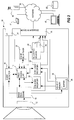
- a video camera 10 implementing one embodiment of the present invention is showed.
- the video camera 10 includes an image sensor 12, an image processing unit 14, a processing unit 16, an event detector 18, a pre event recorder 20, a post event recorder 22, a video sequence recording session processor 24, an event delay timer 26, a buffer 28 arranged in a volatile memory 30, and a non-volatile memory 32.
- the video camera 10 may also, as depicted in Fig 1 , include an Input/Output interface 34 (I/O-interface) for receiving signals indicating external events, and a network interface 36 connecting the camera to a network 38 for communication with video servers, video clients, control devices, display devices, storage devices etc.
- the I/O-interface 34 is not necessary an I/O interface, many applications only need an input interface arranged to receive signals.
- the image sensor 12 is arranged to capture image data and the image processing unit 14 is arranged to process the image data from the image sensor.
- the image sensor 12 and the image processing unit may correspond to known image sensors and known image processing units of available video cameras in which the image processing unit 14 are intended to include known means and devices necessary for outputting a compressed digital stream of video frames.
- the processing unit also is arranged to produce image frames including raw-data.
- the processing unit 16 may be a single or a plurality of processing units arranged to control functions of the camera, e.g. one processor may be arranged to run code implementing particular functionality.
- the event detector 18 of this embodiment is designed to check input signals for changes and determine if the changes corresponds to any predetermined events. When such changes to an input signal are determined to correspond to a predetermined event the event detector indicates that an event is detected.
- the indication of a detected event may, according to one embodiment, include information identifying the type of event detected.
- the event detector 18 is arranged to provide the signal indicating a detected event to the processing unit 16.
- the event detector may be arranged to detect event by analysing images from the image processing unit. Examples of such analysis may be motion detection analysis, crossing a line analysis, facial recognition, tampering, etc. Alternatively or in addition the event detector 18 may be arranged to receive an event signal from an external device via the I/O-interface 34.
- Such event signals may for instance be generated by an external IR-detector, a revolution counter, a temperature sensor, a pressure sensor, an audio sensor, a push-button, a sensor means measuring voltage, means measuring current, means measuring power, means measuring network activity, etc.
- one or a plurality of sensors normally arranged externally to the video camera may be embedded in the video camera or at least arranged in the same housing as the video camera.
- the event detector may also keep an event signal active for as long as the event is in progress, e.g. as long as movement is detected, as long as the temperature is above a specific level, etc.
- the pre event recorder 20 is arranged to record a video sequence preceding a detected event and being of a predetermined length in a non-volatile memory 32.
- the pre event video sequence is retrieved from the Buffer 28 in the volatile memory.
- the pre event recorder 20 may be arranged to record the entire length of the pre event video sequence at once or record every frame to be included as it exits the buffer due to a new video frame entering the buffer.
- One reason for recording video from a point in time preceding the event is that actions, occurrences or incidents happening before the event may be very important in order to correctly interpret the event.
- the length of the pre event recording depends on the action detected and the purpose of the monitoring of such events.
- the post event recorder 22 is arranged to record video being registered by the video camera after the detection of the event for a predetermined time or for as long as an event is in progress, e.g. as long as movement is detected.
- the post event time period may be defined as a predetermined number of post event video frames.
- the post event recorder 22 may be arranged to retrieve the video frames for recording directly from an output of the image processing unit 14 and record the retrieved video frames in the non-volatile memory 32.
- the post event recorder 22 may be arranged to record each video frame of the post event interval when they are leaving the buffer 28 when being old. Thereby the post event recorder 22 perform a delayed recording of a video frame captured by the sensor a delay time period before the recording, the delay time period corresponds to the size of the buffer.
- the video sequence recording session processor 24 includes a video sequence recording session initiator 40 and a video sequence recording session closer 42.
- the video sequence recording session processor 24 is arranged to control a video recording session of a continuous video sequence.
- a video session is started by the video sequence recording session initiator 40 in response to the pre event recorder requesting recording of a pre event and is ended by the video sequence recording session closer 42 in accordance with a scheme being based on signals from the delay timer 26, the pre event recorder 20, and the post event recorder 22.
- the scheme may be executed by the processing unit 16.
- the video sequence recording session initiator 40 may be arranged to setup the non-volatile memory to start storing a continuous video sequence and the video sequence recording session closer 42 may be arranged to end the storing of the continuous video sequence, e.g. the recording session may be seen as the period during which consecutive, in view of time, frames are stored.
- the setup performed by the video sequence recording session initiator 40 may include opening or initiating a file in a file system of the non-volatile memory.
- the ending of the storing of a continuous video sequence may include closing the file opened or initiated by the video sequence recording session initiator 40.
- the event delay timer 26 is a timer that is triggered when the post event recorder 22 has recorded all the frames required for the presently handled event.
- the processing unit 16 consider the state of the event delay timer 26, e.g. if it has expired or if it is running, when deciding on whether the video sequence recording session is to be closed.
- the delay value of the timer is according to one embodiment predetermined to a value corresponding to the length of the pre event recording. In case of a plurality of different event types are recognized by the camera the delay value is set to correspond to the longest pre event recording lengths of all of the different event types recognized.
- the buffer 28 is arranged in the volatile memory 30 to temporarily store sequential video frames for the purpose of enabling retrieval of previously captured video frames if necessary.
- the buffer is therefore implemented as a First In First Out buffer, FIFO-buffer, i.e. a queue.
- the length of the buffer is at least the same length as the longest pre event video frame sequence defined for any event type to be detected by the camera. According to another embodiment the buffer is substantially identical to the longest pre event video frame sequence defined for any event type to be detected by the camera.
- the volatile memory 30 is arranged to include the buffer 28 described above and function as temporary storage for the processing unit when operating the camera.
- the volatile memory may for instance be a Random Access Memory (RAM), e.g. a Static RAM (SRAM) or a Dynamic RAM (DRAM).
- RAM Random Access Memory
- SRAM Static RAM
- DRAM Dynamic RAM
- the non-volatile memory 32 is arranged for long term storage of potentially interesting video sequences and other data that is required or desired to be able to access even after a power failure or after the video camera has not been provided with power during a substantial time period.
- the non-volatile memory 32 is a memory that can retain the stored information even when not powered.
- the non.-volatile memory is a rewriteable non-volatile memory, i.e. a memory that is possible to write and rewrite information to and which still retain stored information when not powered. Examples of such memories are Hard Disk Drives (HDD) having rotating disks, Solid State Drives (SSD), PROM, EPROM, EEPROM, Flash memory.
- the non volatile memory may also be a non-rewriteable memory, e.g. CD-roms, tapes, etching, etc.
- a non-volatile memory may be embedded within the housing of the video camera or connected to the camera via an external interface.
- the external interface is used in order to allow simple exchange of non-volatile memory and may be a simple connector or arranged in a memory connection slot 44 receiving the non-volatile memory.
- the non-volatile memory used may be a CompactFlash (CF), Secure Digital card (SD card), a Memory Stick, etc.
- the network interface 36 may be any known network interface enabling the video camera to connect to the network 38, e.g. a Local Area Network (LAN), a Wide Area Network (WAN), the Internet, etc.
- LAN Local Area Network
- WAN Wide Area Network
- the network interface 36 may be any known network interface enabling the video camera to connect to the network 38, e.g. a Local Area Network (LAN), a Wide Area Network (WAN), the Internet, etc.
- LAN Local Area Network
- WAN Wide Area Network
- the Internet etc.
- Any one of, any combination of, or all of the event detector 18, the pre event recorder 20, the post event recorder 22, the video sequence recording session unit 24 , the event delay timer 26, and the image processing unit 14 may be implemented in software being processed by the processing unit or may be implemented in hardware.
- the video camera 10 includes substantially the same features and means as the video camera 10 of Fig 1 .
- the video sequence recording session processor 24 is arranged to initiate a recording at a storage device 50, 52, 54, 56 connected to the video camera 10 via the network 38.
- the storage device 50, 52, 54, 56 may for example be a server 50, a data base 52, a networked hard drive 54 or solid state drive 54, or a computer 56.
- the pre event recorder 20 and the post event recorder 22 are recording and communicating with a non-volatile memory at the storage device 50, 52, 54, 56 via the network interface 36 and the network 38.
- the camera may be arranged to detect only one type of event type or to detect a plurality of event types.
- An event type is to be understood as an event detected by means of a particular detection scheme, e.g. motion detection and temperature detection may be two different event types and a particular combination of detected motion and a particular temperature may be another event.
- Each event type is related to event type parameters, e.g. number of pre event frames #PrEF and number of post event frames #PoEF.
- each parameter indicating #PrEF may be based on a predefined or user defined value indicating the number of video frames representing a time period of interest before the occurrence of the event in real life and on a value indicating the number of frames representing latency when detecting the particular event.
- each parameter indicating #PrEF may be based on a value indicating the number of video frames representing a predetermined time period of interest before the occurrence of the event in real life and on a dynamic value indicating the number of frames representing latency when detecting the particular event.
- the latency being the true time, measured by the system, it takes from the occurrence of the event until the event detector provide an event detection signal, i.e. the time period from the occurrence of the event to the detection of the event.
- the structure of a recorded event video sequence 100 representing a video of a single event may include a sequence of video frames 100, the number of frames presented in the figure is only selected in order to facilitate understanding of the structure of the video event sequence.
- the sequence of video frames 100 includes pre event video frames 102, which are video image frames captured before the point in time t ed representing the detection of the event triggering the capturing of the event video sequence, and post event video frames 104, which are video image frames captured after the point in time t ed representing the detection of the event.
- the video frames representing the time period of interest before the occurrence of the event is indicated with an A and the video frames representing the latency from occurrence of event to detection of event is in are indicated with a B.
- the buffer size is equal to the largest number of pre event frames MaxPrEF of the all the event types in the camera. According to another embodiment the buffer size is at least equal to the largest number of pre event frames of the all the event types in the camera.
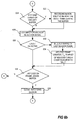
- FIG. 4 A method according to one embodiment for capturing and recording video sequences relating to an event is depicted by the flow charts of Figs 4 , and 5a-5b .
- Fig 4 the general concept of capturing and buffering a video image sequence is described.
- the video camera is directed for capturing video sequences of a scene.
- the image sensor of the video camera registers image data, step 400.
- the procedure and the way in which registration of image data in an image sensor is performed may vary depending on the type of image sensor.
- the registered image data is then processed, step 402, by image processing means in order to generate a video image frame adapted to be positioned in the produced video sequence.
- image processing means may for instance include compression, white balancing, sharpening, adjustment of contrast, Bayer Interpolation, cropping, noise cancelation etc.
- the video image frame is then inserted as the last video image frame in the buffer, step 404.
- the process of event controlled recording of video sequences is running parallel with the capturing of video image frames and may be based on following process.
- the process is arranged to listening for a signal indicating the detection of an event of interest, step 502 and 504. The process continues to listen until an event signal is detected.
- a video sequence recording session is initiated, step 506, and a number of video frames is retrieved from the buffer, step 508.
- the number of video frames retrieved from the buffer corresponds to the number of pre event video frames #PrEF the detected event requires.
- the number of pre event video frames is, as discussed above, a value accessible by the processing unit. The value may be stored as a parameter of the event.
- the frames retrieved are in one embodiment a video frame sequence being of a length corresponding the number of pre event video frames required and starting at the last video frame written to the buffer. This retrieved video sequence is then recorded in the non-volatile memory, step 510, in accordance with the initiated recording session.
- an end of post event time limit, t eop , or a number of post event frames limit is set, step 512. It is not relevant if the limit is set in number of frames or as a time as long as a distinct endpoint for post event frames is provided. Some event types may not have a definite endpoint but is rather to continue record post frames as long as the event is in progress, e.g. as long as movement is present.
- the time limit, t eop , or another variable may indicate if this is the case.
- the next video image frame i.e. the video image frame outputted from the image processing unit following the latest image frame for recording as pre event image frames, is retrieved, step 514, and recorded in the non-volatile memory, step 516.
- step 520 the present post event sequence time limit is reviewed, step 522, by comparing it with a post event sequence time limit resulting from the new detected event. If the post event sequence time limit resulting from the new event expires later than the present post event sequence time limit t eop the present post event sequence time limit t eop is replaced with the post event sequence time limit resulting from the new event. On the other hand, if the present post event sequence time limit t eop still expire later then the present post event sequence time limit t eop is kept.
- an event delay timer T ed is started, step 524.
- the process is arranged to listen for an event detection signal, step 526, and decrement the timer, step 528.
- the event delay timer has a length substantially equal to the largest predetermined number of pre event frames related to the event type parameters of the video camera. If the video camera is arranged to only detect one event type, then the predetermined number of pre event frames of that event type represent the largest predetermined number of pre event frames in the video camera.
- step 530 If no event is detected, step 530, and the event delay timer has not expired, step 532, then the process performs the steps of listening for an event detection signal and decrementing the event delay timer.
- step 532 If no event is detected, step 530, and the event delay timer has expired, step 532, then the process is arranged to close the video sequence recording session, step 534. Video image frames are still being written to the buffer. Then the process returns to steps 502 and 504 listening for an event signal.
- step 530 If an event is detected, step 530, then it is detected before the expiration of the event delay timer and thereby there is a chance that the pre event video frames required by the detected event is temporally overlapped by the post event video frames of the previous event recording.
- the process then retrieves from the video buffer, in response to detecting an event during the running of the event delay timer, all video frames buffered since the recording of post event video frames ended, step 536, and records them in the present video sequence recording session, step 538.
- the process add the video frames captured between the point in time when recording of previous event video was ended, i.e. after step 518, and the detection of the new event, step 530.
- a continuous video sequence including event video relating to more than one event is created and video from two different events is recorded without storing duplicate video frames.
- a post event video frame recording identical to the post event video frame recording for an event requiring a new video sequence recording session as described above may be used.
- the process returns to setting the end of post event time limit, t eop , or setting the number of post event frames, step 512, for the new event.
- One advantage of the above method is that it is possible to use a small amount of volatile memory for on the fly recording of video sequences related to events without excessive use of non-volatile memory. For example, only the video data of interest is recorded in non-volatile memory, thereby also making the non-volatile memory last longer as many non-volatile memories has a limited number of possible write cycles for each memory cell.
- Another, advantage of this particular embodiment is that video frames of interest are recorded in non volatile memory as soon as they are available or as soon as the video camera detects an event. This result from the fact that the video image frames are retrieved and recorded as soon they are available, i.e. directly from the output of the image processing device, and that pre event video frames are retrieved and recorded directly from the buffer without waiting for each of them to pass through.
- the method correspond to the method above with the exception that a plurality of video frames are not retrieved from the buffer at a time.
- the capturing of image data and generating video image frames described in Fig 4 may also be applicable in this embodiment.
- the video frames from the image sensor all are passing through the buffer before recording.
- the buffer is a FIFO buffer and the decision relating to recording image frames relay on a decision of whether the video frame outputted from the buffer is to be recorded in the non-volatile memory or not.
- the process of event controlled recording of video sequences is running parallel with the capturing of video image frames and may be based on the following process.
- the process is arranged to listening for a signal indicating the detection of an event of interest, step 602 and 604. The process continues to listen until an event signal is detected.
- step 506 When an event signal is detected a video sequence recording session is initiated, step 506. Then the video image frame positioned at a position in the buffer being the predetermined number of pre event frames #PrEF from the last video frame inserted in the buffer is marked as a start recording frame, SR, step 608, i.e. the frame buffered #PrEF before the event detection is marked as a SR frame.
- a post frame counter T pf is set to the value of the predetermined number of post event frames #PoEF and a count indicator is set to true, step 610, in order to keep track of the video image frame that are to be the last of this particular event.
- the count indicator indicates, when true, that the last video image frame of the post event sequence has not yet been captured and inserted into the buffer. When the count indicator is false the last video image frame of the post event image frames is present in the buffer.
- the process wait for next video image frame to be inserted in the buffer, step 612.
- the process checks if the count indicator is True or False, step 614. If the count indicator is False, i.e. the last video frame of the post event frames has been inserted in the buffer and the post frame counter is not supposed to count any more, then the process skip all steps relating to finding the last post event frame and proceeds directly to step 624. If the count indicator on the other hand is true, then the process still looks for the last post event frame and the post frame counter T pf is decreased, step 616.
- the post frame counter T pf may be decreased by the value of one or any other value, as long as the counting of frames leads to finding of the last post event frame.
- step 618 the value of the counter is checked, step 618 in order to find out if it has reached a count indicating that the image video frame newly inserted in the buffer is the last post event frame. According to one embodiment this is indicated by the counter when it has reached zero. If the last post event frame has not been inserted in the buffer and the post then the process continues to step 624. However, if the last post event frame has been inserted in the buffer, e.g. the counter T pf has reached zero, then the latest video image frame inserted in the buffer is marked as being the last session frame, step 620, and the count indicator is set to false, step 622, and the process continues to step 624.
- step 624 the process checks if the start recording, SR, frame has reached the end of the buffer and is leaving the buffer and if the SR frame has left the buffer earlier. If the SR frame is leaving or has left the buffer the video image frame leaving the buffer is recorded in non-volatile memory, step 626. Then the process proceeds to step 628 for listening for an event detection signal.
- step 628 If the SR frame is not leaving or has not left the buffer then the process proceeds to step 628 for listening for an event detection signal.
- step 630 at this stage of the process it means either that pre event image frames or post event image frames of a previously detected event are advancing through the buffer to be recorded in the non-volatile memory. Because the length of the buffer correspond substantially to the maximal number of pre event frames of a single event, an event that is detected during this time period is likely to have video image frames overlapping or being very close in time to the image frames of the previously detected event and accordingly we want these to be recorded in the same recording session in order not to create an excess of data or writing cycles. In order to achieve that the marking of a last session frame is deleted, if such frame has been marked yet, step 632.
- step 634 the post frame counter T pf is set to a value corresponding to the number of post event frames of the new event and the count indicator is set to "True", step 634.
- step 630 If no event is detected in step 630, then the process also continues to step 636 in which the process checks if the frame marked as the last session frame is leaving the buffer.
- the recording session is closed and the process returns to step 602 waiting for detection of a new event. Otherwise, if no frame marked as last session frame is found leaving the buffer then the process returns to step 612 waiting for the next video frame to be buffered.
- the buffer itself acts as a delay channel or a timing buffer in order to make sure that the recording session is not closed until we are certain that no overlapping pre event frames may be the result of a detection of a new event.
- an override functionality relating to the marking of the last session frame in cases of events not having a definite endpoint, as discussed in the embodiment depicted in Figs 5a-b .
- This override should enable recording of post frames as long as such event is active and stop recording post frames if such event is no longer active and no post frame counter is counting for an event having a fixed number of post event frames.
- the time for end of the post event sequence or the number of frames left until the last session frame is captured changes in order to record both events in the same recording session. Further, if the new event is detected after the time for end of the post event sequence has expired or after the last session frame has been captured and the time between the expiration or the capture of the last session frame and the first pre event frame requested by the new event are overlapping, then the process is arranged to record the video image frames of the new event in the same session continue adding video image frames to the sequence of the previous event.
- the buffer will include video image frames not requested by any event.
- One way to handle it is to determine that all new events detected within the time corresponding to the maximum number of prevent image frames is incorporated in the earlier session even if video image frames not requested will be recorded.
- Another way to handle it is to check when the new event is detected if the buffer includes video image frames not requested by any event. If video image frames not requested is found then end the previous recording session at the last video image frame of the earlier event and start a new recording session for the new event.
- the process of handling events is started and the buffer and an event list is initiated and a variable named currently recording is set to FALSE, step 702.
- the event list may be a self-balancing binary search three, e.g. AA tree, AVL tree, Red-black tree, Scapegoat tree, Splay tree, Treap, etc.
- AA tree AA tree
- AVL tree Red-black tree
- Scapegoat tree Splay tree
- Treap Treap
- the process calculates a start frame number, and an end frame number for the event, step 706, using the parameters of the detected event. These parameters may be, as previously described, number of pre event frames, number of post event frames, latency, etc and the start frame number and the end frame number being values identifying these particular frames.
- the detection of an event, step 706, may also trigger sending of some kind of alarm, indication or the like.
- a new element is added to the event list, step 708.
- the element includes at least the start frame number and the end frame number and the list is, in this particular embodiment, sorted on start frame number, in order to increase the search speed.
- the process returns to step 704 and waits for a new event or a new frame.
- step 704 If, in step 704, a new frame is detected the process proceeds to step 710, and sets a variable named old frame # to the frame number of the frame that is to exit the buffer due to the new frame being inserted. This old frame # is used to determine if the process is to start recording or end recording and may be set to a specific value if buffer is not full, e.g. a negative value. Then the process checks if the buffer is full, step 712. If the buffer is not full the process proceeds to step 714 inserting the frame into the buffer and proceeds with the steps of the process following step 714. If the buffer is full, then the process checks if the event list is empty, step 716. If the event list is empty, the process continues to step 718.
- step 720 If the event list is not empty the start frame number of the first element in the sorted event list or the element with the lowest start frame number in a non-sorted event list is retrieved, step 720. If this start frame number is not equal to and not less than the old frame # then the frame corresponding to the start frame number have not reached the end of the buffer and the process proceeds to step 718 to process this situation. If, on the other hand, the start frame number is equal to or less than the old frame # then the process continues to check if a session is currently recorded. This is performed by means of checking if currently recording is TRUE or FALSE in step 724.
- step 726 If FALSE the process initiates the recording session and sets the currently recording variable to TRUE, step 726, and then the process records the "old" frame, i.e. the frame exiting the buffer, step 728. If the check at step 724 discovers that the process is currently recording in a recording session then the process goes directly to recording the "old" frame, step 728. When the frame has been recorded the process proceeds to step 714 and insert frame in buffer.
- the check 718 relating to whether the process is currently recording or not is performed at step 718. This particular check is performed in response to the event list being empty, step 716, or in response to the start frame number not being equal to or less than the old frame #, step 722, and is performed in order to determine whether a recording session is to be ended or not. If the variable named currently recording is FALSE in step 718, then there is no recording session to end and the process insert the frame in the buffer, step 714. If the variable named currently recording is TRUE in step 718, then the process end the ongoing recording session and sets the variable named currently recording to FALSE, step 730. Then the process insert the frame in the buffer, step 714.
- step 732 After the insertion of the frame in the buffer a check is performed in the event list, step 732. If the event list is empty the process returns to step 704 waiting for a new frame or a new event. Otherwise, if the event list is not empty the process retrieves the end frame number of the first element in the sorted event list or of the element with the lowest start frame number in a non-sorted event list, step 734, and checks if the end frame number is less than or equal to the value of the old frame #. If the end frame number is less than or equal to the value of the old frame #, then the first element of the event list is obsolete and is therefore deleted, step 738. Then the process returns to checking if the event list is empty, step 732, in order to check if additional events may be deleted. However, if the end frame number is not less than and not equal to the value of the old frame #, step 736, then the first element of the event list is still relevant and the process returns to step 704 waiting for a new event or a new frame.
- This process may also implement events not having a definite endpoint.
- the recording session is not allowed to end as long as such event not having a definite endpoint is in progress. This may be indicated by setting the end frame number of the event to a special value, e.g. a negative value. When the end of such an event is detected the end frame number is set.
- the process may record post event relating to events having a predetermined post event length and events that are to be recorded for the entire time the event is indicated as active.
- Yet another embodiment may include the functionality of the embodiment described in Figs 7a-c , except for the use of the variable "currently recording" and the functionality of steps 724, 726, 718, and 730.
- the operation of such a process is identical to the operation as described in relation to Figs 7a-c above except that no recording sessions are initiated or ended.
Description
- The present invention relates to systems or cameras used in recording video sequences relating to specified events. More particularly the invention relates to a method for generating an event initiated video sequence and a video camera arranged for event initiated recording of video sequences.
- Video camera systems are widely used for capturing video images for surveillance purposes in offices, banks, in parking lots, on the streets, in homes etc. or for monitoring purposes in a production line or similar. However, recordings from such camera systems may include one single interesting event representing a few seconds among hours of video that is of no particular interest at all. Hence, there are a couple of problems with such systems. It is for instance very difficult to find a relatively short event of interest in a very long video recording. Moreover, the recording of all video requires a lot of storage space. Therefore, many monitoring and surveillance video cameras is arranged to detect events or be triggered by an external signal indicating an event. This extra information is in some implementations used to indicate where in the vast video recording the events of interest are positioned. In other implementations these events triggers the recording of the video of the event. For some events the video following after the event is of most interest, for other events the video preceding the event is of most interest, and for yet other events it is a combination of the above that are of most interest. Hence a relatively small sized file or stream of video is generated and is transmitted for remote storing in relation to each event detection.
- Moreover, a video camera may be arranged to detect a plurality of different events resulting in an increased risk of events detected in a video camera occurring simultaneously and thereby resulting in two files or streams including at least some identical video image frames and thereby using up additional storage space or bandwidth.
- In
EP 0 898 770 - In
WO 01/35668 - In
WO 99/56216 - In
US 2009/0207247 A1 a surveillance system including an event module for receiving an event detection signal indicating an event external to the surveillance system. The system also includes a power control module that selectively operates a data recording device at least partially concurrent with the event based on the event detection signal. The system also includes a selection module that selects a portion of data recorded by the data recording device based on content of the data. - In
EP 0 898 770 - One object of the present invention is to provide an improved method and an improved camera for event initiated video capturing.
- The object is achieved by means of a method according to
claim 1 and video camera according to claim 9. Further embodiments of the invention are presented in the dependent claims. - In particular, according to a first aspect of the present invention, the object is achieved by means of a method for recording an event initiated video sequence, said method comprises continuously capturing video frames, temporarily storing video frames in a video buffer, detecting a first event, initiating, in response to the detection of the first event, a video sequence recording session for recording of a video sequence in a non-volatile memory by initiating writing of a file in the non-volatile memory, recording in the single file in the non-volatile memory pre event frames of the captured video data present in the buffer, this recording is performed in response to the detection of the first event, recording in the single file in the non-volatile memory post event frames of the video data captured during a post event time period related to the first event, the post event time period is starting at the detection of the first event, starting an event delay timer arranged to time a first event delay time period starting at a point in time of expiration of the post event time period of the first event and ending at a first delay expiration time, if said first event delay period expires and no other event process is in progress then the video sequence recording session and said single file is closed, wherein an event process includes recording pre event frames, recording post event frames, and an event delay time period, and wherein the delay period is a period counted from the expiration of a post event time period, if a second event is detected after expiration of the post event time period of the first event and before expiration of the first event delay time period then: recording of frames, from the video buffer representing a time period starting at the expiration of the post event time period of the first event and ending at the detection of the second event, is performed in the single file in the non-volatile memory in response to detection of the second event, and recording, in the single file in the non-volatile memory, memory frames of the video data captured during a post event time period related to the second event, the post event time period is starting at the detection of the second event.
- By introducing an event delay timer and making this timer control the closing of the recording session it becomes possible to effectively store event initiated video sequences because this procedure enables the camera to record different events without recording duplicate video frames even when the event require recording of pre event video frames, i.e. video frames representing the scenery a time period preceding the detection of the event.
- According to one embodiment the size of the video buffer substantially corresponds to a maximal number of pre event frames. The advantage of this feature is that the size of the memory in which the buffer resides may be small. Thereby, the cost and the overall size of the camera may be reduced.
- According to another embodiment the predetermined number of pre event frames is defined by at least two parameters, wherein the first parameter is an arbitrary value defining the desired amount of video preceding the event and the second parameter is a latency period corresponding to the time difference between an occurrence of an event and a detection of the same event. By considering the latency of the detection process as well as the time period the event is required to record, the size of the pre event recordings may be made very accurate and thereby may the size of the required buffer memory be determined more exactly.
- According to yet another embodiment the video buffer is of First In First Out, FIFO, type.
- In one embodiment the act of initiating a video sequence recording session comprises the act of setting up a file in the non-volatile memory to include the recorded video session and wherein the act of closing the video sequence recording session comprises the act of closing the file.
- In another embodiment the acts of capturing video frames, temporarily storing video frames in a video buffer, detecting a first event, initiating a video sequence recording session, recording pre event frames of the first event, recording post event frames of the first event, detecting a second event, recording pre event frames of the second event, recording post event frames of the second event, and closing the video sequence recording session all are performed at a camera.
- According to one embodiment the non-volatile memory is arranged in a camera.
- According to another embodiment the buffer is arranged in a camera and the non volatile memory is arranged in a device connecting to the camera via a network, and wherein the act of initiating a video sequence recording session comprises the act of setting up a video stream over the network and a file in the non-volatile memory to transfer the video stream over the network and store the recorded video session in the file, and wherein the act of closing the video sequence recording session comprises the act of closing the file and the video stream. By applying the method in a system recording over a network the method is further advantageous in that it saves bandwidth.
- According to yet another embodiment a detected event may be of any event type of a plurality of event types and wherein the method further comprises indicating the event type of any detected event and retrieving values specifying the predetermined number of pre event frames the predetermined number of post event frames of the indicated event type.
- According to a second aspect of the invention a video camera arranged for event initiated capturing of video sequences comprises an image sensor arranged to continuously capture video frames, a video buffer arrange to temporarily store video frames, an event detector, a video sequence recording session initiator arranged to initiate, in response to a detection of an event, a video sequence recording session for recording of a video sequence in a non-volatile memory by initiating writing of a file in the non-volatile memory, a pre event recorder arranged to record in the initiated video sequence recording session to the single file in the non-volatile memory a number of pre event frames of the captured video data present in the buffer, the pre event recorder is further arranged to perform the recording in response to the detection of the first event, a post event recorder arranged to record in the initiated video sequence recording session to the single file in the non-volatile memory post event frames of the video data captured during a post event time period related to the detected event, the post event time period is starting at the detection of the event and ranging a number of post event frames, an event delay timer arranged to time an event delay time period starting at a point in time of an expiration of a post event time period and ending at a detay expiration timem a video sequence recording session closer arranged to close the video sequence recording session and the single file if the event delay period expires and no other event process is in progress, wherein an event process includes recording pre event frames, recording post event frames, and an event delay time period.
- According to one embodiment of the second aspect the size of the video buffer substantially corresponds to a maximal number of pre event frames. The advantage of this feature is that the size of the memory in which the buffer resides may be small. Thereby, the cost and the overall size of the camera may be reduced.
- According to another embodiment the number of pre event frames is defined by at least two parameters, wherein the first parameter is an arbitrary value defining the desired amount of video preceding the event and the second parameter is a latency period corresponding to the time difference between an occurrence of an event and a detection of the same event. By considering the latency of the detection process as well as the time period the event is required to record, the size of the pre event recordings may be made very accurate and thereby may the size of the required buffer memory be determined more exactly.
- According to yet another embodiment the video buffer is of First In First Out, FIFO, type.
- In another embodiment the video sequence recording session initiator is further arranged to set up a file in the non-volatile memory to include the recorded video session and wherein the video sequence recording session closer is further arranged to close the file.
- A further scope of applicability of the present invention will become apparent from the detailed description given below. However, it should be understood that the detailed description and specific examples, while indicating preferred embodiments of the invention, are given by way of illustration only.
- Other features and advantages of the present invention will become apparent from the following detailed description of embodiments, with reference to the accompanying drawings, in which:
-
Fig 1 is a schematic view of one embodiment of a video camera according to the invention; -
Fig 2 is a schematic view of another embodiment of a video camera according to the invention; -
Fig 3 shows an example structure of an event initiated video sequence; -
Fig 4 shows a flowchart over a general process of capturing and buffering a video image sequence; -
Fig 5a-b show a flowchart over a method recording an event initiated video sequence according to one embodiment of the invention; -
Fig 6a-b show a flowchart over a method recording an event initiated video sequence according to another embodiment of the invention; and -
Fig 7a-c show a flowchart over a method recording an event initiated video sequence according to yet another embodiment of the invention. - Below a detailed description of embodiments is disclosed referring to the drawings in which like numerals indicates the same or similar features.
- In
Fig 1 avideo camera 10 implementing one embodiment of the present invention is showed. Thevideo camera 10 includes animage sensor 12, animage processing unit 14, aprocessing unit 16, anevent detector 18, apre event recorder 20, apost event recorder 22, a video sequencerecording session processor 24, anevent delay timer 26, abuffer 28 arranged in avolatile memory 30, and anon-volatile memory 32. Thevideo camera 10 may also, as depicted inFig 1 , include an Input/Output interface 34 (I/O-interface) for receiving signals indicating external events, and anetwork interface 36 connecting the camera to anetwork 38 for communication with video servers, video clients, control devices, display devices, storage devices etc. The I/O-interface 34 is not necessary an I/O interface, many applications only need an input interface arranged to receive signals. - The
image sensor 12 is arranged to capture image data and theimage processing unit 14 is arranged to process the image data from the image sensor. Theimage sensor 12 and the image processing unit may correspond to known image sensors and known image processing units of available video cameras in which theimage processing unit 14 are intended to include known means and devices necessary for outputting a compressed digital stream of video frames. According to one embodiment the processing unit also is arranged to produce image frames including raw-data. - The
processing unit 16 may be a single or a plurality of processing units arranged to control functions of the camera, e.g. one processor may be arranged to run code implementing particular functionality. - The
event detector 18 of this embodiment is designed to check input signals for changes and determine if the changes corresponds to any predetermined events. When such changes to an input signal are determined to correspond to a predetermined event the event detector indicates that an event is detected. The indication of a detected event may, according to one embodiment, include information identifying the type of event detected. Theevent detector 18 is arranged to provide the signal indicating a detected event to theprocessing unit 16. The event detector may be arranged to detect event by analysing images from the image processing unit. Examples of such analysis may be motion detection analysis, crossing a line analysis, facial recognition, tampering, etc. Alternatively or in addition theevent detector 18 may be arranged to receive an event signal from an external device via the I/O-interface 34. Such event signals may for instance be generated by an external IR-detector, a revolution counter, a temperature sensor, a pressure sensor, an audio sensor, a push-button, a sensor means measuring voltage, means measuring current, means measuring power, means measuring network activity, etc. In some applications one or a plurality of sensors normally arranged externally to the video camera may be embedded in the video camera or at least arranged in the same housing as the video camera. The event detector may also keep an event signal active for as long as the event is in progress, e.g. as long as movement is detected, as long as the temperature is above a specific level, etc. - The
pre event recorder 20 is arranged to record a video sequence preceding a detected event and being of a predetermined length in anon-volatile memory 32. The pre event video sequence is retrieved from theBuffer 28 in the volatile memory. Thepre event recorder 20 may be arranged to record the entire length of the pre event video sequence at once or record every frame to be included as it exits the buffer due to a new video frame entering the buffer. One reason for recording video from a point in time preceding the event is that actions, occurrences or incidents happening before the event may be very important in order to correctly interpret the event. The length of the pre event recording depends on the action detected and the purpose of the monitoring of such events. - The
post event recorder 22 is arranged to record video being registered by the video camera after the detection of the event for a predetermined time or for as long as an event is in progress, e.g. as long as movement is detected. The post event time period may be defined as a predetermined number of post event video frames. Thepost event recorder 22 may be arranged to retrieve the video frames for recording directly from an output of theimage processing unit 14 and record the retrieved video frames in thenon-volatile memory 32. According to another embodiment thepost event recorder 22 may be arranged to record each video frame of the post event interval when they are leaving thebuffer 28 when being old. Thereby thepost event recorder 22 perform a delayed recording of a video frame captured by the sensor a delay time period before the recording, the delay time period corresponds to the size of the buffer. - The video sequence
recording session processor 24 includes a video sequencerecording session initiator 40 and a video sequence recording session closer 42. The video sequencerecording session processor 24 is arranged to control a video recording session of a continuous video sequence. A video session is started by the video sequencerecording session initiator 40 in response to the pre event recorder requesting recording of a pre event and is ended by the video sequence recording session closer 42 in accordance with a scheme being based on signals from thedelay timer 26, thepre event recorder 20, and thepost event recorder 22. The scheme may be executed by theprocessing unit 16. - In the embodiment of
Fig 1 the video sequencerecording session initiator 40 may be arranged to setup the non-volatile memory to start storing a continuous video sequence and the video sequence recording session closer 42 may be arranged to end the storing of the continuous video sequence, e.g. the recording session may be seen as the period during which consecutive, in view of time, frames are stored. The setup performed by the video sequencerecording session initiator 40 may include opening or initiating a file in a file system of the non-volatile memory. The ending of the storing of a continuous video sequence may include closing the file opened or initiated by the video sequencerecording session initiator 40. - The
event delay timer 26 is a timer that is triggered when thepost event recorder 22 has recorded all the frames required for the presently handled event. Theprocessing unit 16 consider the state of theevent delay timer 26, e.g. if it has expired or if it is running, when deciding on whether the video sequence recording session is to be closed. The delay value of the timer is according to one embodiment predetermined to a value corresponding to the length of the pre event recording. In case of a plurality of different event types are recognized by the camera the delay value is set to correspond to the longest pre event recording lengths of all of the different event types recognized. - The
buffer 28 is arranged in thevolatile memory 30 to temporarily store sequential video frames for the purpose of enabling retrieval of previously captured video frames if necessary. The buffer is therefore implemented as a First In First Out buffer, FIFO-buffer, i.e. a queue. - According to one embodiment the length of the buffer is at least the same length as the longest pre event video frame sequence defined for any event type to be detected by the camera. According to another embodiment the buffer is substantially identical to the longest pre event video frame sequence defined for any event type to be detected by the camera.
- The
volatile memory 30 is arranged to include thebuffer 28 described above and function as temporary storage for the processing unit when operating the camera. The volatile memory may for instance be a Random Access Memory (RAM), e.g. a Static RAM (SRAM) or a Dynamic RAM (DRAM). - The
non-volatile memory 32 is arranged for long term storage of potentially interesting video sequences and other data that is required or desired to be able to access even after a power failure or after the video camera has not been provided with power during a substantial time period. Hence, thenon-volatile memory 32 is a memory that can retain the stored information even when not powered. In this particular embodiment the non.-volatile memory is a rewriteable non-volatile memory, i.e. a memory that is possible to write and rewrite information to and which still retain stored information when not powered. Examples of such memories are Hard Disk Drives (HDD) having rotating disks, Solid State Drives (SSD), PROM, EPROM, EEPROM, Flash memory. However, the non volatile memory may also be a non-rewriteable memory, e.g. CD-roms, tapes, etching, etc. - A non-volatile memory may be embedded within the housing of the video camera or connected to the camera via an external interface. The external interface is used in order to allow simple exchange of non-volatile memory and may be a simple connector or arranged in a
memory connection slot 44 receiving the non-volatile memory. In one embodiment implementing amemory connection slot 44, the non-volatile memory used may be a CompactFlash (CF), Secure Digital card (SD card), a Memory Stick, etc. - The
network interface 36 may be any known network interface enabling the video camera to connect to thenetwork 38, e.g. a Local Area Network (LAN), a Wide Area Network (WAN), the Internet, etc. - Any one of, any combination of, or all of the
event detector 18, thepre event recorder 20, thepost event recorder 22, the video sequencerecording session unit 24 , theevent delay timer 26, and theimage processing unit 14 may be implemented in software being processed by the processing unit or may be implemented in hardware. - According to another embodiment, see
Fig 2 , thevideo camera 10 includes substantially the same features and means as thevideo camera 10 ofFig 1 . The difference between the embodiment ofFig 2 and the embodiment ofFig 1 is that the video sequencerecording session processor 24 is arranged to initiate a recording at astorage device video camera 10 via thenetwork 38. Thestorage device server 50, adata base 52, a networkedhard drive 54 orsolid state drive 54, or acomputer 56. Accordingly thepre event recorder 20 and thepost event recorder 22 are recording and communicating with a non-volatile memory at thestorage device network interface 36 and thenetwork 38. - The camera may be arranged to detect only one type of event type or to detect a plurality of event types. An event type is to be understood as an event detected by means of a particular detection scheme, e.g. motion detection and temperature detection may be two different event types and a particular combination of detected motion and a particular temperature may be another event. Each event type is related to event type parameters, e.g. number of pre event frames #PrEF and number of post event frames #PoEF.
- According to one embodiment each parameter indicating #PrEF may be based on a predefined or user defined value indicating the number of video frames representing a time period of interest before the occurrence of the event in real life and on a value indicating the number of frames representing latency when detecting the particular event. The latency representing the time it takes from the occurrence of the event until the event detector provide an event detection signal, i.e. the time period from the occurrence of the event to the detection of the event.
- According to another embodiment each parameter indicating #PrEF may be based on a value indicating the number of video frames representing a predetermined time period of interest before the occurrence of the event in real life and on a dynamic value indicating the number of frames representing latency when detecting the particular event. The latency being the true time, measured by the system, it takes from the occurrence of the event until the event detector provide an event detection signal, i.e. the time period from the occurrence of the event to the detection of the event.
- Now referring to
Fig 3 , the structure of a recordedevent video sequence 100 representing a video of a single event may include a sequence of video frames 100, the number of frames presented in the figure is only selected in order to facilitate understanding of the structure of the video event sequence. The sequence of video frames 100 includes pre event video frames 102, which are video image frames captured before the point in time ted representing the detection of the event triggering the capturing of the event video sequence, and post event video frames 104, which are video image frames captured after the point in time ted representing the detection of the event. The video frames representing the time period of interest before the occurrence of the event is indicated with an A and the video frames representing the latency from occurrence of event to detection of event is in are indicated with a B. - According to one embodiment the buffer size is equal to the largest number of pre event frames MaxPrEF of the all the event types in the camera. According to another embodiment the buffer size is at least equal to the largest number of pre event frames of the all the event types in the camera.
- By considering the latency of the event detection as well as the time period of interest when determining the number of it is possible to more accurately determine the minimal length of a pre event time period and thereby it becomes possible to optimise the size of the buffer and thereby the utilisation of the volatile memory.
- A method according to one embodiment for capturing and recording video sequences relating to an event is depicted by the flow charts of
Figs 4 , and5a-5b . InFig 4 the general concept of capturing and buffering a video image sequence is described. - The video camera is directed for capturing video sequences of a scene. The image sensor of the video camera registers image data,
step 400. The procedure and the way in which registration of image data in an image sensor is performed may vary depending on the type of image sensor. - The registered image data is then processed,
step 402, by image processing means in order to generate a video image frame adapted to be positioned in the produced video sequence. The processing of image data may for instance include compression, white balancing, sharpening, adjustment of contrast, Bayer Interpolation, cropping, noise cancelation etc. - The video image frame is then inserted as the last video image frame in the buffer,
step 404. - The process of event controlled recording of video sequences is running parallel with the capturing of video image frames and may be based on following process. The process is arranged to listening for a signal indicating the detection of an event of interest,
step - When an event signal is detected a video sequence recording session is initiated,
step 506, and a number of video frames is retrieved from the buffer,step 508. The number of video frames retrieved from the buffer corresponds to the number of pre event video frames #PrEF the detected event requires. The number of pre event video frames is, as discussed above, a value accessible by the processing unit. The value may be stored as a parameter of the event. In cases of The frames retrieved are in one embodiment a video frame sequence being of a length corresponding the number of pre event video frames required and starting at the last video frame written to the buffer. This retrieved video sequence is then recorded in the non-volatile memory,step 510, in accordance with the initiated recording session. In connection with the event detection an end of post event time limit, teop, or a number of post event frames limit is set,step 512. It is not relevant if the limit is set in number of frames or as a time as long as a distinct endpoint for post event frames is provided. Some event types may not have a definite endpoint but is rather to continue record post frames as long as the event is in progress, e.g. as long as movement is present. The time limit, teop, or another variable may indicate if this is the case. - The next video image frame, i.e. the video image frame outputted from the image processing unit following the latest image frame for recording as pre event image frames, is retrieved,
step 514, and recorded in the non-volatile memory,step 516. The steps of retrieving the next image captured and recording the retrieved image, steps 514 and 516, is then repeated until the predetermined number of post event video frames has been recorded or, if described using time, until the time limit teop for the post event sequence has expired,step 518. If the event is a type not having a definite endpoint thestep 518 may be designed to repeat until the event no longer is in progress. - If a new event is detected,
step 520, during the recording of the post event video frames, the present post event sequence time limit is reviewed,step 522, by comparing it with a post event sequence time limit resulting from the new detected event. If the post event sequence time limit resulting from the new event expires later than the present post event sequence time limit teop the present post event sequence time limit teop is replaced with the post event sequence time limit resulting from the new event. On the other hand, if the present post event sequence time limit teop still expire later then the present post event sequence time limit teop is kept. - Then when the post event sequence time limit teop has expired and no more event video recordings are in progress an event delay timer Ted is started,
step 524. Now referring toFig 5b , as long as the event delay timer Ted has not expired the process is arranged to listen for an event detection signal,step 526, and decrement the timer,step 528. During the running of the event delay timer video image frames are written to the buffer. The event delay timer has a length substantially equal to the largest predetermined number of pre event frames related to the event type parameters of the video camera. If the video camera is arranged to only detect one event type, then the predetermined number of pre event frames of that event type represent the largest predetermined number of pre event frames in the video camera. - If no event is detected,
step 530, and the event delay timer has not expired,step 532, then the process performs the steps of listening for an event detection signal and decrementing the event delay timer. - If no event is detected,
step 530, and the event delay timer has expired,step 532, then the process is arranged to close the video sequence recording session,step 534. Video image frames are still being written to the buffer. Then the process returns tosteps - If an event is detected,
step 530, then it is detected before the expiration of the event delay timer and thereby there is a chance that the pre event video frames required by the detected event is temporally overlapped by the post event video frames of the previous event recording. In the present embodiment the process then retrieves from the video buffer, in response to detecting an event during the running of the event delay timer, all video frames buffered since the recording of post event video frames ended,step 536, and records them in the present video sequence recording session,step 538. In other words, the process add the video frames captured between the point in time when recording of previous event video was ended, i.e. afterstep 518, and the detection of the new event,step 530. Thereby a continuous video sequence including event video relating to more than one event is created and video from two different events is recorded without storing duplicate video frames. - Moreover, a post event video frame recording identical to the post event video frame recording for an event requiring a new video sequence recording session as described above may be used. Hence the process returns to setting the end of post event time limit, teop, or setting the number of post event frames,
step 512, for the new event. - One advantage of the above method is that it is possible to use a small amount of volatile memory for on the fly recording of video sequences related to events without excessive use of non-volatile memory. For example, only the video data of interest is recorded in non-volatile memory, thereby also making the non-volatile memory last longer as many non-volatile memories has a limited number of possible write cycles for each memory cell. Another, advantage of this particular embodiment is that video frames of interest are recorded in non volatile memory as soon as they are available or as soon as the video camera detects an event. This result from the fact that the video image frames are retrieved and recorded as soon they are available, i.e. directly from the output of the image processing device, and that pre event video frames are retrieved and recorded directly from the buffer without waiting for each of them to pass through.
- According to another embodiment, see
Figs 6a-6b , the method correspond to the method above with the exception that a plurality of video frames are not retrieved from the buffer at a time. The capturing of image data and generating video image frames described inFig 4 may also be applicable in this embodiment. In this method the video frames from the image sensor all are passing through the buffer before recording. The buffer is a FIFO buffer and the decision relating to recording image frames relay on a decision of whether the video frame outputted from the buffer is to be recorded in the non-volatile memory or not. - The process of event controlled recording of video sequences is running parallel with the capturing of video image frames and may be based on the following process. The process is arranged to listening for a signal indicating the detection of an event of interest,
step - When an event signal is detected a video sequence recording session is initiated,
step 506. Then the video image frame positioned at a position in the buffer being the predetermined number of pre event frames #PrEF from the last video frame inserted in the buffer is marked as a start recording frame, SR,step 608, i.e. the frame buffered #PrEF before the event detection is marked as a SR frame. - Then a post frame counter Tpf is set to the value of the predetermined number of post event frames #PoEF and a count indicator is set to true,
step 610, in order to keep track of the video image frame that are to be the last of this particular event. The count indicator indicates, when true, that the last video image frame of the post event sequence has not yet been captured and inserted into the buffer. When the count indicator is false the last video image frame of the post event image frames is present in the buffer. Now when the first video image of the event has been inserted in the buffer and the earliest pre event frame has been marked, the process wait for next video image frame to be inserted in the buffer,step 612. - When the next video image frame is inserted, the process check if the count indicator is True or False,
step 614. If the count indicator is False, i.e. the last video frame of the post event frames has been inserted in the buffer and the post frame counter is not supposed to count any more, then the process skip all steps relating to finding the last post event frame and proceeds directly to step 624. If the count indicator on the other hand is true, then the process still looks for the last post event frame and the post frame counter Tpf is decreased,step 616. The post frame counter Tpf may be decreased by the value of one or any other value, as long as the counting of frames leads to finding of the last post event frame. - Then the value of the counter is checked,
step 618 in order to find out if it has reached a count indicating that the image video frame newly inserted in the buffer is the last post event frame. According to one embodiment this is indicated by the counter when it has reached zero. If the last post event frame has not been inserted in the buffer and the post then the process continues to step 624. However, if the last post event frame has been inserted in the buffer, e.g. the counter Tpf has reached zero, then the latest video image frame inserted in the buffer is marked as being the last session frame, step 620, and the count indicator is set to false, step 622, and the process continues to step 624. - In
step 624 the process checks if the start recording, SR, frame has reached the end of the buffer and is leaving the buffer and if the SR frame has left the buffer earlier. If the SR frame is leaving or has left the buffer the video image frame leaving the buffer is recorded in non-volatile memory,step 626. Then the process proceeds to step 628 for listening for an event detection signal. - If the SR frame is not leaving or has not left the buffer then the process proceeds to step 628 for listening for an event detection signal.
- If an event detection signal is detected,
step 630, at this stage of the process it means either that pre event image frames or post event image frames of a previously detected event are advancing through the buffer to be recorded in the non-volatile memory. Because the length of the buffer correspond substantially to the maximal number of pre event frames of a single event, an event that is detected during this time period is likely to have video image frames overlapping or being very close in time to the image frames of the previously detected event and accordingly we want these to be recorded in the same recording session in order not to create an excess of data or writing cycles. In order to achieve that the marking of a last session frame is deleted, if such frame has been marked yet,step 632. Then the post frame counter Tpf is set to a value corresponding to the number of post event frames of the new event and the count indicator is set to "True",step 634. Thereby the process will find a new last session frame, which is related to the new event, and the process continues recording in non-volatile memory the frames exiting the buffer. When these procedures are finished the process continues to step 636. - If no event is detected in
step 630, then the process also continues to step 636 in which the process checks if the frame marked as the last session frame is leaving the buffer. - If the frame marked as the last session frame is recorded and, thus, is leaving the buffer then the recording session is closed and the process returns to step 602 waiting for detection of a new event. Otherwise, if no frame marked as last session frame is found leaving the buffer then the process returns to step 612 waiting for the next video frame to be buffered.
- In this embodiment the buffer itself acts as a delay channel or a timing buffer in order to make sure that the recording session is not closed until we are certain that no overlapping pre event frames may be the result of a detection of a new event.
- It is possible to add an override functionality relating to the marking of the last session frame in cases of events not having a definite endpoint, as discussed in the embodiment depicted in
Figs 5a-b . This override should enable recording of post frames as long as such event is active and stop recording post frames if such event is no longer active and no post frame counter is counting for an event having a fixed number of post event frames. - In the above embodiments of the method it is described that if a new event is detected when event frames from previous event are still captured then the time for end of the post event sequence or the number of frames left until the last session frame is captured changes in order to record both events in the same recording session. Further, if the new event is detected after the time for end of the post event sequence has expired or after the last session frame has been captured and the time between the expiration or the capture of the last session frame and the first pre event frame requested by the new event are overlapping, then the process is arranged to record the video image frames of the new event in the same session continue adding video image frames to the sequence of the previous event. However, there is a case when the number of pre event image frames requested by the new event is smaller than the maximum number of prevent image frames defined in the system and the temporal distance between the detection of the new event is and the last frame of the earlier event is greater than the time corresponding to the number of pre event image frames requested by the new event. Hence, the buffer will include video image frames not requested by any event. This situation may be handled in a couple of ways. One way to handle it is to determine that all new events detected within the time corresponding to the maximum number of prevent image frames is incorporated in the earlier session even if video image frames not requested will be recorded. Another way to handle it is to check when the new event is detected if the buffer includes video image frames not requested by any event. If video image frames not requested is found then end the previous recording session at the last video image frame of the earlier event and start a new recording session for the new event.
- According to yet another embodiment, see
Figs 7a-7c , the process of handling events is started and the buffer and an event list is initiated and a variable named currently recording is set to FALSE,step 702. The event list may be a self-balancing binary search three, e.g. AA tree, AVL tree, Red-black tree, Scapegoat tree, Splay tree, Treap, etc. The evident advantage of using such a structure for this particular list is that adding and sorting new elements will be fast. - Then the process waits for an event to be detected or a new frame to be captured,
step 704. - If an event is detected the process calculates a start frame number, and an end frame number for the event,
step 706, using the parameters of the detected event. These parameters may be, as previously described, number of pre event frames, number of post event frames, latency, etc and the start frame number and the end frame number being values identifying these particular frames. The detection of an event,step 706, may also trigger sending of some kind of alarm, indication or the like. Then a new element is added to the event list,step 708. The element includes at least the start frame number and the end frame number and the list is, in this particular embodiment, sorted on start frame number, in order to increase the search speed. When the event has been added the process returns to step 704 and waits for a new event or a new frame. - If, in
step 704, a new frame is detected the process proceeds to step 710, and sets a variable named old frame # to the frame number of the frame that is to exit the buffer due to the new frame being inserted. This old frame # is used to determine if the process is to start recording or end recording and may be set to a specific value if buffer is not full, e.g. a negative value. Then the process checks if the buffer is full,step 712. If the buffer is not full the process proceeds to step 714 inserting the frame into the buffer and proceeds with the steps of theprocess following step 714. If the buffer is full, then the process checks if the event list is empty,step 716. If the event list is empty, the process continues to step 718. - However, if the event list is not empty the start frame number of the first element in the sorted event list or the element with the lowest start frame number in a non-sorted event list is retrieved,
step 720. If this start frame number is not equal to and not less than the old frame # then the frame corresponding to the start frame number have not reached the end of the buffer and the process proceeds to step 718 to process this situation. If, on the other hand, the start frame number is equal to or less than the old frame # then the process continues to check if a session is currently recorded. This is performed by means of checking if currently recording is TRUE or FALSE instep 724. If FALSE the process initiates the recording session and sets the currently recording variable to TRUE,step 726, and then the process records the "old" frame, i.e. the frame exiting the buffer,step 728. If the check atstep 724 discovers that the process is currently recording in a recording session then the process goes directly to recording the "old" frame,step 728. When the frame has been recorded the process proceeds to step 714 and insert frame in buffer. - The
check 718 relating to whether the process is currently recording or not is performed atstep 718. This particular check is performed in response to the event list being empty,step 716, or in response to the start frame number not being equal to or less than the old frame #,step 722, and is performed in order to determine whether a recording session is to be ended or not. If the variable named currently recording is FALSE instep 718, then there is no recording session to end and the process insert the frame in the buffer,step 714. If the variable named currently recording is TRUE instep 718, then the process end the ongoing recording session and sets the variable named currently recording to FALSE,step 730. Then the process insert the frame in the buffer,step 714. After the insertion of the frame in the buffer a check is performed in the event list,step 732. If the event list is empty the process returns to step 704 waiting for a new frame or a new event. Otherwise, if the event list is not empty the process retrieves the end frame number of the first element in the sorted event list or of the element with the lowest start frame number in a non-sorted event list,step 734, and checks if the end frame number is less than or equal to the value of the old frame #. If the end frame number is less than or equal to the value of the old frame #, then the first element of the event list is obsolete and is therefore deleted,step 738. Then the process returns to checking if the event list is empty,step 732, in order to check if additional events may be deleted. However, if the end frame number is not less than and not equal to the value of the old frame #,step 736, then the first element of the event list is still relevant and the process returns to step 704 waiting for a new event or a new frame. - This process, described referring to
Figs 7a-c , may also implement events not having a definite endpoint. The only difference in such implementation is that the recording session is not allowed to end as long as such event not having a definite endpoint is in progress. This may be indicated by setting the end frame number of the event to a special value, e.g. a negative value. When the end of such an event is detected the end frame number is set. Thereby, the process may record post event relating to events having a predetermined post event length and events that are to be recorded for the entire time the event is indicated as active. - Yet another embodiment may include the functionality of the embodiment described in
Figs 7a-c , except for the use of the variable "currently recording" and the functionality ofsteps Figs 7a-c above except that no recording sessions are initiated or ended. - All the processes described above, referring to
Figs 4 ,5a-b ,6a-b and7a-c , may be implemented in a video camera. The skilled person realises that the implementation may be in the form of software or by means of logic circuits.
Claims (13)
- Method for recording an event initiated video sequence, said method comprising:continuously capturing video frames,temporarily storing video frames in a video buffer,detecting a first event,initiating, in response to the detection of the first event, a video sequence recording session for recording of a video sequence as a single file in a non-volatile memory by initiating writing of a file in the non-volatile memory,recording in the single file in the non-volatile memory pre event frames of the captured video data present in the buffer, this recording is performed in response to the detection of the first event,recording in the single file in the non-volatile memory post event frames of the video data captured during a post event time period related to the first event, the post event time period is starting at the detection of the first event,starting an event delay timer arranged to time a first event delay time period starting at a point in time of expiration of the post event time period of the first event and ending at a first delay expiration time,if said first event delay period expires and no other event process is in progress then the video sequence recording session and said single file is closed, wherein an event process includes recording pre event frames, recording post event frames, and an event delay time period, and wherein the delay period is a period counted from the expiration of a post event time period,if a second event is detected after expiration of the post event time period of the first event and before expiration of the first event delay time period then:recording of frames, from the video buffer representing a time period starting at the expiration of the post event time period of the first event and ending at the detection of the second event, is performed in the single file in the non-volatile memory in response to detection of the second event, andrecording, in the single file in the non-volatile memory, frames of the video data captured during a post event time period related to the second event, the post event time period is starting at the detection of the second event.
- Method according to claim 1, wherein the size of the video buffer substantially corresponds to the predetermined number of pre event frames.
- Method according to claim 2, wherein the number of pre event frames to be recorded is defined by at least two parameters, wherein the first parameter is an arbitrary value defining the desired amount of video preceding the event and the second parameter is a latency period corresponding to the time difference between an occurrence of an event and a detection of the same event.
- Method according to any one of claims 1-3, further comprising determining an event type every detected event, wherein a number of pre-event video frames is event type dependent, and wherein the event delay timer has a length substantially equal to the largest number of pre-event frames related to the event type parameters of the video camera.
- Method according to any one of claims 1-4, wherein the video buffer is of First In First Out, FIFO, type.
- Method according to any one of claims 1-5, wherein the acts of capturing video frames, temporarily storing video frames in a video buffer, detecting a first event, initiating a video sequence recording session, recording pre event frames of the first event, recording post event frames of the first event, detecting a second event, recording pre event frames of the second event, recording post event frames of the second event, and closing the video sequence recording session all are performed at a camera.
- Method according to any one of claims 1-6, wherein the non-volatile memory is arranged in a camera.
- Method according to any one of claims 1-5, wherein the buffer is arranged in a camera and the non volatile memory is arranged in a device connecting to the camera via a network, and wherein the act of initiating a video sequence recording session comprises the act of setting up a video stream over the network and a file in the non-volatile memory to transfer the video stream over the network and store the recorded video session in the file, and wherein the act of closing the video sequence recording session comprises the act of closing the file and the video stream.
- Method according to any one of claims 1-8, wherein a detected event may be of any event type of a plurality of event types and wherein the method further comprises indicating the event type of any detected event and retrieving values specifying the predetermined number of pre event frames the predetermined number of post event frames of the indicated event type.
- Video camera arranged for event initiated recording of video sequences, said video camera comprising:an image sensor arranged to continuously capture video frames,a video buffer arrange to temporarily store video frames,an event detector,characterised by:a video sequence recording session initiator arranged to initiate, in response to a detection of an event, a video sequence recording session for recording of a video sequence as a single file in a non-volatile memory by initiating writing of a file in the non-volatile memory,a pre event recorder arranged to record in the initiated video sequence recording session to the single file in the non-volatile memory a number of pre event frames of the captured video data present in the buffer, the pre event recorder is further arranged to perform the recording in response to the detection of the first event,a post event recorder arranged to record in the initiated video sequence recording session to the single file in the non-volatile memory post event frames of the video data captured during a post event time period related to the detected event, the post event time period is starting at the detection of the event and ranging a number of post event frames,an event delay timer arranged to time an event delay time period starting at a point in time of an expiration of a post event time period and ending at a delay expiration time,a video sequence recording session closer arranged to close the video sequence recording session and the single file if the event delay time period expires and no other event process is in progress, wherein an event process includes recording pre event frames, recording post event frames, and an event delay time period.
- Video camera according to claim 10, wherein the size of the video buffer substantially corresponds to a maximal number of pre event frames.
- Video camera according to claim 11, wherein the number of pre event frames is defined by at least two parameters, wherein the first parameter is an arbitrary value defining the desired amount of video preceding the event and the second parameter is a latency period corresponding to the time difference between an occurrence of an event and a detection of the same event.
- Video camera according to any one of claims 10-12, wherein the video buffer is of First In First Out, FIFO, type.
Priority Applications (3)
| Application Number | Priority Date | Filing Date | Title |
|---|---|---|---|
| EP10169879.3A EP2407943B1 (en) | 2010-07-16 | 2010-07-16 | Method for event initiated video capturing and a video camera for capture event initiated video |
| CN201110198478.6A CN102340625B (en) | 2010-07-16 | 2011-07-11 | The video camera of the video capture method that event starts and the video that capturing events starts |
| US13/183,942 US8676027B2 (en) | 2010-07-16 | 2011-07-15 | Method for event initiated video capturing and a video camera for capture event initiated video |
Applications Claiming Priority (1)
| Application Number | Priority Date | Filing Date | Title |
|---|---|---|---|
| EP10169879.3A EP2407943B1 (en) | 2010-07-16 | 2010-07-16 | Method for event initiated video capturing and a video camera for capture event initiated video |
Publications (2)
| Publication Number | Publication Date |
|---|---|
| EP2407943A1 EP2407943A1 (en) | 2012-01-18 |
| EP2407943B1 true EP2407943B1 (en) | 2016-09-28 |
Family
ID=42635296
Family Applications (1)
| Application Number | Title | Priority Date | Filing Date |
|---|---|---|---|
| EP10169879.3A Active EP2407943B1 (en) | 2010-07-16 | 2010-07-16 | Method for event initiated video capturing and a video camera for capture event initiated video |
Country Status (3)
| Country | Link |
|---|---|
| US (1) | US8676027B2 (en) |
| EP (1) | EP2407943B1 (en) |
| CN (1) | CN102340625B (en) |
Cited By (5)
| Publication number | Priority date | Publication date | Assignee | Title |
|---|---|---|---|---|
| US9472029B2 (en) | 2006-03-16 | 2016-10-18 | Smartdrive Systems, Inc. | Vehicle event recorder systems and networks having integrated cellular wireless communications systems |
| US9501878B2 (en) | 2013-10-16 | 2016-11-22 | Smartdrive Systems, Inc. | Vehicle event playback apparatus and methods |
| US9554080B2 (en) | 2006-11-07 | 2017-01-24 | Smartdrive Systems, Inc. | Power management systems for automotive video event recorders |
| US9594371B1 (en) | 2014-02-21 | 2017-03-14 | Smartdrive Systems, Inc. | System and method to detect execution of driving maneuvers |
| US9633318B2 (en) | 2005-12-08 | 2017-04-25 | Smartdrive Systems, Inc. | Vehicle event recorder systems |
Families Citing this family (61)
| Publication number | Priority date | Publication date | Assignee | Title |
|---|---|---|---|---|
| US20070150138A1 (en) | 2005-12-08 | 2007-06-28 | James Plante | Memory management in event recording systems |
| US8996240B2 (en) | 2006-03-16 | 2015-03-31 | Smartdrive Systems, Inc. | Vehicle event recorders with integrated web server |
| US8989959B2 (en) | 2006-11-07 | 2015-03-24 | Smartdrive Systems, Inc. | Vehicle operator performance history recording, scoring and reporting systems |
| US8868288B2 (en) | 2006-11-09 | 2014-10-21 | Smartdrive Systems, Inc. | Vehicle exception event management systems |
| US8239092B2 (en) | 2007-05-08 | 2012-08-07 | Smartdrive Systems Inc. | Distributed vehicle event recorder systems having a portable memory data transfer system |
| JP5570176B2 (en) * | 2009-10-19 | 2014-08-13 | キヤノン株式会社 | Image processing system and information processing method |
| US9728228B2 (en) | 2012-08-10 | 2017-08-08 | Smartdrive Systems, Inc. | Vehicle event playback apparatus and methods |
| US10692591B2 (en) | 2013-02-01 | 2020-06-23 | B-Line Medical, Llc | Apparatus, method and computer readable medium for tracking data and events |
| ITVI20130027A1 (en) * | 2013-02-08 | 2014-08-09 | Gianni Giglioli | SYSTEM FOR ACTIVE AND REMOTE SURVEILLANCE AND PROCEDURE THAT IMPLEMENTS THIS SYSTEM |
| CN103227934B (en) * | 2013-04-19 | 2017-07-28 | 深圳Tcl新技术有限公司 | The method and server that TV programme are recorded a video |
| US20150010289A1 (en) * | 2013-07-03 | 2015-01-08 | Timothy P. Lindblom | Multiple retail device universal data gateway |
| US9610955B2 (en) | 2013-11-11 | 2017-04-04 | Smartdrive Systems, Inc. | Vehicle fuel consumption monitor and feedback systems |
| US20150213838A1 (en) * | 2014-01-30 | 2015-07-30 | Imperx, Inc. | Network based video event recording system |
| US20150221337A1 (en) * | 2014-02-03 | 2015-08-06 | Jong Wan Kim | Secondary Video Generation Method |
| US9313401B2 (en) | 2014-03-04 | 2016-04-12 | Here Global B.V. | Frame rate designation region |
| US10341684B2 (en) * | 2014-03-07 | 2019-07-02 | Eagle Eye Networks, Inc. | High definition surveillance image storage optimization apparatus and methods of retention triggering |
| CN104023208B (en) * | 2014-06-05 | 2019-07-05 | 北京小鱼在家科技有限公司 | A kind of device and method of automatic monitoring and autonomic response |
| US9892378B2 (en) * | 2014-07-31 | 2018-02-13 | BluePoint Mobile Solutoins, Inc. | Devices, systems and methods for tracking and auditing shipment items |
| US20160125714A1 (en) * | 2014-11-04 | 2016-05-05 | Canary Connect, Inc. | Video recording with security/safety monitoring device |
| US11069257B2 (en) | 2014-11-13 | 2021-07-20 | Smartdrive Systems, Inc. | System and method for detecting a vehicle event and generating review criteria |
| EP3070695B1 (en) * | 2015-03-16 | 2017-06-14 | Axis AB | Method and system for generating an event video sequence, and camera comprising such system |
| US9679420B2 (en) | 2015-04-01 | 2017-06-13 | Smartdrive Systems, Inc. | Vehicle event recording system and method |
| CN104836972A (en) * | 2015-04-30 | 2015-08-12 | 徐友华 | Real-time shooting device with forward time-delay storage function and shooting method |
| US10819943B2 (en) * | 2015-05-07 | 2020-10-27 | Magna Electronics Inc. | Vehicle vision system with incident recording function |
| EP3298797A4 (en) * | 2015-05-22 | 2019-01-30 | Playsight Interactive Ltd. | Event based video generation |
| FR3047596A1 (en) * | 2016-02-08 | 2017-08-11 | Grime | VIDEO SURVEILLANCE METHOD FROM AT LEAST ONE CAMERA AND VIDEO SURVEILLANCE INSTALLATION FOR IMPLEMENTING SAID METHOD |
| CN106251888A (en) * | 2016-07-29 | 2016-12-21 | 南京云恩通讯科技有限公司 | A kind of method temporally managing recording |
| CN107888870B (en) * | 2016-09-29 | 2020-01-17 | 杭州海康威视数字技术股份有限公司 | Monitoring method, device and system |
| CN109565564B (en) | 2016-11-18 | 2021-07-02 | Jvc 建伍株式会社 | Recording device, recording method, reproducing method, and storage medium |
| EP3328051B1 (en) * | 2016-11-29 | 2019-01-02 | Axis AB | Method for controlling an infrared cut filter of a video camera |
| EP3340103A1 (en) * | 2016-12-21 | 2018-06-27 | Axis AB | Method for identifying events in a motion video |
| EP3340105A1 (en) * | 2016-12-21 | 2018-06-27 | Axis AB | Method for and apparatus for detecting events |
| US10412346B1 (en) * | 2017-03-09 | 2019-09-10 | Chengfu Yu | Dual video signal monitoring and management of a personal internet protocol surveillance camera |
| JP6996384B2 (en) * | 2018-03-27 | 2022-01-17 | 富士通株式会社 | Display program, display method and display device |
| US10372991B1 (en) * | 2018-04-03 | 2019-08-06 | Google Llc | Systems and methods that leverage deep learning to selectively store audiovisual content |
| JP2019193089A (en) * | 2018-04-24 | 2019-10-31 | 東芝テック株式会社 | Video analysis device |
| CN108668096B (en) * | 2018-05-18 | 2021-08-20 | 京东方科技集团股份有限公司 | Video data management method and device and video recording equipment |
| US10730463B2 (en) * | 2018-06-11 | 2020-08-04 | Ford Global Technologies, Llc | Tigger based vehicle monitoring |
| CN109089075A (en) * | 2018-07-10 | 2018-12-25 | 浙江工商大学 | Embedded across cloud intelligence memory method and system |
| US11024137B2 (en) * | 2018-08-08 | 2021-06-01 | Digital Ally, Inc. | Remote video triggering and tagging |
| CN108965831B (en) * | 2018-09-05 | 2020-09-25 | 北京疯景科技有限公司 | Video processing method and device and intelligent visual doorbell |
| EP3713226A1 (en) * | 2018-09-28 | 2020-09-23 | Axis AB | Content security for a video stream |
| US10897627B2 (en) | 2019-01-11 | 2021-01-19 | Western Digital Technologies, Inc. | Non-volatile memory system including a partial decoder and event detector for video streams |
| WO2020165978A1 (en) * | 2019-02-13 | 2020-08-20 | オリンパス株式会社 | Image recording device, image recording method, and image recording program |
| CN110069659A (en) * | 2019-04-23 | 2019-07-30 | 上海天诚比集科技有限公司 | Alarm event video pictures store method based on round-robin queue |
| US11036435B2 (en) | 2019-08-30 | 2021-06-15 | Western Digital Technologies, Inc. | Search time optimization in solid-state devices |
| US11343474B2 (en) * | 2019-10-02 | 2022-05-24 | Qualcomm Incorporated | Image capture based on action recognition |
| US11334389B2 (en) * | 2019-10-23 | 2022-05-17 | Microsoft Technology Licensing, Llc | Adaptive scheduling of latency-sensitive event-based processors |
| US11064194B2 (en) | 2019-10-31 | 2021-07-13 | Western Digital Technologies, Inc. | Encoding digital videos using controllers of data storage devices |
| US10841645B1 (en) | 2019-12-09 | 2020-11-17 | Western Digital Technologies, Inc. | Storage system and method for video frame segregation to optimize storage |
| CN113079311B (en) * | 2020-01-06 | 2023-06-27 | 北京小米移动软件有限公司 | Image acquisition method and device, electronic equipment and storage medium |
| US11526435B2 (en) | 2020-02-04 | 2022-12-13 | Western Digital Technologies, Inc. | Storage system and method for automatic data phasing |
| US11562018B2 (en) | 2020-02-04 | 2023-01-24 | Western Digital Technologies, Inc. | Storage system and method for optimized surveillance search |
| US11328511B2 (en) | 2020-03-13 | 2022-05-10 | Western Digital Technologies, Inc. | Storage system and method for improved playback analysis |
| US11385819B2 (en) * | 2020-08-17 | 2022-07-12 | Micron Technology, Inc. | Separate partition for buffer and snapshot memory |
| CN114079820A (en) * | 2020-08-19 | 2022-02-22 | 安霸国际有限合伙企业 | Interval shooting video generation centered on an event/object of interest input on a camera device by means of a neural network |
| CN112291520B (en) * | 2020-10-26 | 2022-12-06 | 浙江大华技术股份有限公司 | Abnormal event identification method and device, storage medium and electronic device |
| CN114827713B (en) * | 2021-01-21 | 2023-08-08 | Oppo广东移动通信有限公司 | Video processing method and device, computer readable storage medium and electronic equipment |
| EP4054184A1 (en) * | 2021-03-02 | 2022-09-07 | Axis AB | Event video sequences |
| CN115442656B (en) * | 2021-06-04 | 2023-08-15 | 中国移动通信集团浙江有限公司 | Video head and tail automatic detection method, device, equipment and storage medium |
| US20230350820A1 (en) * | 2022-04-28 | 2023-11-02 | Infineon Technologies Ag | Systems and methods for concurrent logging and event capture |
Family Cites Families (14)
| Publication number | Priority date | Publication date | Assignee | Title |
|---|---|---|---|---|
| PT898770E (en) | 1995-03-06 | 2002-02-28 | Bell Addison | COMPUTER ASSISTED SYSTEM OF ACQUISITION OF EVENTS WITH FLEXIVEL STORAGE |
| US5996023A (en) * | 1996-10-31 | 1999-11-30 | Sensormatic Electronics Corporation | Efficient pre-alarm buffer management in intelligent video information management system |
| US6421080B1 (en) * | 1999-11-05 | 2002-07-16 | Image Vault Llc | Digital surveillance system with pre-event recording |
| US20020163577A1 (en) | 2001-05-07 | 2002-11-07 | Comtrak Technologies, Inc. | Event detection in a video recording system |
| JP4099973B2 (en) * | 2001-10-30 | 2008-06-11 | 松下電器産業株式会社 | Video data transmission method, video data reception method, and video surveillance system |
| JP2004140484A (en) * | 2002-10-16 | 2004-05-13 | Sony Corp | Image capturing apparatus and image capturing method |
| WO2004038643A2 (en) * | 2002-10-25 | 2004-05-06 | Mcpheely Bernard M | Digital diagnosti video system for manufacturing and industrial process |
| JP2005312022A (en) * | 2004-03-25 | 2005-11-04 | Matsushita Electric Ind Co Ltd | Audio-visual recording/reproducing apparatus and digital video camera |
| US7843491B2 (en) | 2005-04-05 | 2010-11-30 | 3Vr Security, Inc. | Monitoring and presenting video surveillance data |
| US20070217761A1 (en) * | 2006-03-07 | 2007-09-20 | Coban Research And Technologies, Inc. | Method for video/audio recording using unrestricted pre-event/post-event buffering with multiple bit and frame rates buffer files |
| US8345097B2 (en) * | 2008-02-15 | 2013-01-01 | Harris Corporation | Hybrid remote digital recording and acquisition system |
| US10341615B2 (en) | 2008-03-07 | 2019-07-02 | Honeywell International Inc. | System and method for mapping of text events from multiple sources with camera outputs |
| US8237856B2 (en) * | 2008-11-07 | 2012-08-07 | Looxcie, Inc. | Timeshifting video recording camera |
| US8558888B2 (en) | 2009-02-27 | 2013-10-15 | Third Iris Corp. | Bandwidth shaping client to capture, transform, cache, and upload images from a remote point of recordation to a network service |
-
2010
- 2010-07-16 EP EP10169879.3A patent/EP2407943B1/en active Active
-
2011
- 2011-07-11 CN CN201110198478.6A patent/CN102340625B/en active Active
- 2011-07-15 US US13/183,942 patent/US8676027B2/en active Active
Cited By (7)
| Publication number | Priority date | Publication date | Assignee | Title |
|---|---|---|---|---|
| US9633318B2 (en) | 2005-12-08 | 2017-04-25 | Smartdrive Systems, Inc. | Vehicle event recorder systems |
| US9472029B2 (en) | 2006-03-16 | 2016-10-18 | Smartdrive Systems, Inc. | Vehicle event recorder systems and networks having integrated cellular wireless communications systems |
| US9545881B2 (en) | 2006-03-16 | 2017-01-17 | Smartdrive Systems, Inc. | Vehicle event recorder systems and networks having integrated cellular wireless communications systems |
| US9566910B2 (en) | 2006-03-16 | 2017-02-14 | Smartdrive Systems, Inc. | Vehicle event recorder systems and networks having integrated cellular wireless communications systems |
| US9554080B2 (en) | 2006-11-07 | 2017-01-24 | Smartdrive Systems, Inc. | Power management systems for automotive video event recorders |
| US9501878B2 (en) | 2013-10-16 | 2016-11-22 | Smartdrive Systems, Inc. | Vehicle event playback apparatus and methods |
| US9594371B1 (en) | 2014-02-21 | 2017-03-14 | Smartdrive Systems, Inc. | System and method to detect execution of driving maneuvers |
Also Published As
| Publication number | Publication date |
|---|---|
| US20120014659A1 (en) | 2012-01-19 |
| CN102340625A (en) | 2012-02-01 |
| EP2407943A1 (en) | 2012-01-18 |
| US8676027B2 (en) | 2014-03-18 |
| CN102340625B (en) | 2015-10-14 |
Similar Documents
| Publication | Publication Date | Title |
|---|---|---|
| EP2407943B1 (en) | Method for event initiated video capturing and a video camera for capture event initiated video | |
| US6421080B1 (en) | Digital surveillance system with pre-event recording | |
| US8374746B2 (en) | Memory management in event recording systems | |
| EP1073964B1 (en) | Efficient pre-alarm buffer management | |
| JP4099973B2 (en) | Video data transmission method, video data reception method, and video surveillance system | |
| US9041803B2 (en) | Method for video/audio recording using multiple resolutions | |
| US5946445A (en) | Media recorder for capture and playback of live and prerecorded audio and/or video information | |
| US20030044168A1 (en) | Event image recording system and event image recording method | |
| US11893796B2 (en) | Methods and systems for detection of anomalous motion in a video stream and for creating a video summary | |
| EP2835801A1 (en) | Security surveillance apparatus with networking and video recording functions and failure detecting and repairing method for storage device thereof | |
| WO2018024165A1 (en) | Method and device for storing warning image | |
| KR100793233B1 (en) | Method for changing device informtaion | |
| CN111787256B (en) | Management method, device, medium and electronic equipment for pre-alarm video | |
| JPH1098679A (en) | Recording medium saving recording method for monitor system | |
| WO2001008416A1 (en) | Digital image recording system | |
| JP2009200757A (en) | Video data processing apparatus, program, and method | |
| JP2006254270A (en) | Apparatus and method for recording image | |
| CN114285989A (en) | Self-adaptive adjustment method and device for emergency video trigger threshold | |
| CN104660968B (en) | A kind of method using multi-memory card storage warning message | |
| KR100350219B1 (en) | System for writing image and method for writing image using communication network | |
| CN110990239A (en) | System and method for collecting user data in user equipment based on soft sensor | |
| JP2014155014A (en) | Imaging apparatus, and imaging apparatus control method | |
| CN111666453B (en) | Video management and retrieval method and device, electronic equipment and storage medium | |
| JP4766896B2 (en) | Surveillance video processing device | |
| EP3672233A1 (en) | Method for carrying out a health check of cameras and a camera system |
Legal Events
| Date | Code | Title | Description |
|---|---|---|---|
| AK | Designated contracting states |
Kind code of ref document: A1 Designated state(s): AL AT BE BG CH CY CZ DE DK EE ES FI FR GB GR HR HU IE IS IT LI LT LU LV MC MK MT NL NO PL PT RO SE SI SK SM TR |
|
| AX | Request for extension of the european patent |
Extension state: BA ME RS |
|
| PUAI | Public reference made under article 153(3) epc to a published international application that has entered the european phase |
Free format text: ORIGINAL CODE: 0009012 |
|
| 17P | Request for examination filed |
Effective date: 20120625 |
|
| 17Q | First examination report despatched |
Effective date: 20121017 |
|
| GRAP | Despatch of communication of intention to grant a patent |
Free format text: ORIGINAL CODE: EPIDOSNIGR1 |
|
| INTG | Intention to grant announced |
Effective date: 20160419 |
|
| GRAS | Grant fee paid |
Free format text: ORIGINAL CODE: EPIDOSNIGR3 |
|
| GRAA | (expected) grant |
Free format text: ORIGINAL CODE: 0009210 |
|
| AK | Designated contracting states |
Kind code of ref document: B1 Designated state(s): AL AT BE BG CH CY CZ DE DK EE ES FI FR GB GR HR HU IE IS IT LI LT LU LV MC MK MT NL NO PL PT RO SE SI SK SM TR |
|
| REG | Reference to a national code |
Ref country code: GB Ref legal event code: FG4D |
|
| REG | Reference to a national code |
Ref country code: CH Ref legal event code: EP |
|
| REG | Reference to a national code |
Ref country code: AT Ref legal event code: REF Ref document number: 833334 Country of ref document: AT Kind code of ref document: T Effective date: 20161015 |
|
| REG | Reference to a national code |
Ref country code: IE Ref legal event code: FG4D |
|
| REG | Reference to a national code |
Ref country code: SE Ref legal event code: TRGR |
|
| REG | Reference to a national code |
Ref country code: DE Ref legal event code: R096 Ref document number: 602010036708 Country of ref document: DE |
|
| REG | Reference to a national code |
Ref country code: LT Ref legal event code: MG4D |
|
| PG25 | Lapsed in a contracting state [announced via postgrant information from national office to epo] |
Ref country code: FI Free format text: LAPSE BECAUSE OF FAILURE TO SUBMIT A TRANSLATION OF THE DESCRIPTION OR TO PAY THE FEE WITHIN THE PRESCRIBED TIME-LIMIT Effective date: 20160928 Ref country code: NO Free format text: LAPSE BECAUSE OF FAILURE TO SUBMIT A TRANSLATION OF THE DESCRIPTION OR TO PAY THE FEE WITHIN THE PRESCRIBED TIME-LIMIT Effective date: 20161228 Ref country code: LT Free format text: LAPSE BECAUSE OF FAILURE TO SUBMIT A TRANSLATION OF THE DESCRIPTION OR TO PAY THE FEE WITHIN THE PRESCRIBED TIME-LIMIT Effective date: 20160928 Ref country code: HR Free format text: LAPSE BECAUSE OF FAILURE TO SUBMIT A TRANSLATION OF THE DESCRIPTION OR TO PAY THE FEE WITHIN THE PRESCRIBED TIME-LIMIT Effective date: 20160928 |
|
| REG | Reference to a national code |
Ref country code: NL Ref legal event code: MP Effective date: 20160928 |
|
| REG | Reference to a national code |
Ref country code: AT Ref legal event code: MK05 Ref document number: 833334 Country of ref document: AT Kind code of ref document: T Effective date: 20160928 |
|
| PG25 | Lapsed in a contracting state [announced via postgrant information from national office to epo] |
Ref country code: NL Free format text: LAPSE BECAUSE OF FAILURE TO SUBMIT A TRANSLATION OF THE DESCRIPTION OR TO PAY THE FEE WITHIN THE PRESCRIBED TIME-LIMIT Effective date: 20160928 Ref country code: LV Free format text: LAPSE BECAUSE OF FAILURE TO SUBMIT A TRANSLATION OF THE DESCRIPTION OR TO PAY THE FEE WITHIN THE PRESCRIBED TIME-LIMIT Effective date: 20160928 Ref country code: GR Free format text: LAPSE BECAUSE OF FAILURE TO SUBMIT A TRANSLATION OF THE DESCRIPTION OR TO PAY THE FEE WITHIN THE PRESCRIBED TIME-LIMIT Effective date: 20161229 |
|
| PG25 | Lapsed in a contracting state [announced via postgrant information from national office to epo] |
Ref country code: EE Free format text: LAPSE BECAUSE OF FAILURE TO SUBMIT A TRANSLATION OF THE DESCRIPTION OR TO PAY THE FEE WITHIN THE PRESCRIBED TIME-LIMIT Effective date: 20160928 Ref country code: RO Free format text: LAPSE BECAUSE OF FAILURE TO SUBMIT A TRANSLATION OF THE DESCRIPTION OR TO PAY THE FEE WITHIN THE PRESCRIBED TIME-LIMIT Effective date: 20160928 |
|
| PG25 | Lapsed in a contracting state [announced via postgrant information from national office to epo] |
Ref country code: PT Free format text: LAPSE BECAUSE OF FAILURE TO SUBMIT A TRANSLATION OF THE DESCRIPTION OR TO PAY THE FEE WITHIN THE PRESCRIBED TIME-LIMIT Effective date: 20170130 Ref country code: CZ Free format text: LAPSE BECAUSE OF FAILURE TO SUBMIT A TRANSLATION OF THE DESCRIPTION OR TO PAY THE FEE WITHIN THE PRESCRIBED TIME-LIMIT Effective date: 20160928 Ref country code: AT Free format text: LAPSE BECAUSE OF FAILURE TO SUBMIT A TRANSLATION OF THE DESCRIPTION OR TO PAY THE FEE WITHIN THE PRESCRIBED TIME-LIMIT Effective date: 20160928 Ref country code: ES Free format text: LAPSE BECAUSE OF FAILURE TO SUBMIT A TRANSLATION OF THE DESCRIPTION OR TO PAY THE FEE WITHIN THE PRESCRIBED TIME-LIMIT Effective date: 20160928 Ref country code: PL Free format text: LAPSE BECAUSE OF FAILURE TO SUBMIT A TRANSLATION OF THE DESCRIPTION OR TO PAY THE FEE WITHIN THE PRESCRIBED TIME-LIMIT Effective date: 20160928 Ref country code: SK Free format text: LAPSE BECAUSE OF FAILURE TO SUBMIT A TRANSLATION OF THE DESCRIPTION OR TO PAY THE FEE WITHIN THE PRESCRIBED TIME-LIMIT Effective date: 20160928 Ref country code: BE Free format text: LAPSE BECAUSE OF FAILURE TO SUBMIT A TRANSLATION OF THE DESCRIPTION OR TO PAY THE FEE WITHIN THE PRESCRIBED TIME-LIMIT Effective date: 20160928 Ref country code: BG Free format text: LAPSE BECAUSE OF FAILURE TO SUBMIT A TRANSLATION OF THE DESCRIPTION OR TO PAY THE FEE WITHIN THE PRESCRIBED TIME-LIMIT Effective date: 20161228 Ref country code: SM Free format text: LAPSE BECAUSE OF FAILURE TO SUBMIT A TRANSLATION OF THE DESCRIPTION OR TO PAY THE FEE WITHIN THE PRESCRIBED TIME-LIMIT Effective date: 20160928 Ref country code: IS Free format text: LAPSE BECAUSE OF FAILURE TO SUBMIT A TRANSLATION OF THE DESCRIPTION OR TO PAY THE FEE WITHIN THE PRESCRIBED TIME-LIMIT Effective date: 20170128 |
|
| REG | Reference to a national code |
Ref country code: FR Ref legal event code: PLFP Year of fee payment: 8 |
|
| REG | Reference to a national code |
Ref country code: DE Ref legal event code: R097 Ref document number: 602010036708 Country of ref document: DE |
|
| PG25 | Lapsed in a contracting state [announced via postgrant information from national office to epo] |
Ref country code: IT Free format text: LAPSE BECAUSE OF FAILURE TO SUBMIT A TRANSLATION OF THE DESCRIPTION OR TO PAY THE FEE WITHIN THE PRESCRIBED TIME-LIMIT Effective date: 20160928 |
|
| PG25 | Lapsed in a contracting state [announced via postgrant information from national office to epo] |
Ref country code: DK Free format text: LAPSE BECAUSE OF FAILURE TO SUBMIT A TRANSLATION OF THE DESCRIPTION OR TO PAY THE FEE WITHIN THE PRESCRIBED TIME-LIMIT Effective date: 20160928 |
|
| PLBE | No opposition filed within time limit |
Free format text: ORIGINAL CODE: 0009261 |
|
| STAA | Information on the status of an ep patent application or granted ep patent |
Free format text: STATUS: NO OPPOSITION FILED WITHIN TIME LIMIT |
|
| 26N | No opposition filed |
Effective date: 20170629 |
|
| PG25 | Lapsed in a contracting state [announced via postgrant information from national office to epo] |
Ref country code: SI Free format text: LAPSE BECAUSE OF FAILURE TO SUBMIT A TRANSLATION OF THE DESCRIPTION OR TO PAY THE FEE WITHIN THE PRESCRIBED TIME-LIMIT Effective date: 20160928 |
|
| REG | Reference to a national code |
Ref country code: CH Ref legal event code: PL |
|
| REG | Reference to a national code |
Ref country code: IE Ref legal event code: MM4A |
|
| PG25 | Lapsed in a contracting state [announced via postgrant information from national office to epo] |
Ref country code: IE Free format text: LAPSE BECAUSE OF NON-PAYMENT OF DUE FEES Effective date: 20170716 Ref country code: CH Free format text: LAPSE BECAUSE OF NON-PAYMENT OF DUE FEES Effective date: 20170731 Ref country code: LI Free format text: LAPSE BECAUSE OF NON-PAYMENT OF DUE FEES Effective date: 20170731 |
|
| REG | Reference to a national code |
Ref country code: FR Ref legal event code: PLFP Year of fee payment: 9 |
|
| PG25 | Lapsed in a contracting state [announced via postgrant information from national office to epo] |
Ref country code: LU Free format text: LAPSE BECAUSE OF NON-PAYMENT OF DUE FEES Effective date: 20170716 |
|
| PG25 | Lapsed in a contracting state [announced via postgrant information from national office to epo] |
Ref country code: MT Free format text: LAPSE BECAUSE OF NON-PAYMENT OF DUE FEES Effective date: 20170716 |
|
| PG25 | Lapsed in a contracting state [announced via postgrant information from national office to epo] |
Ref country code: AL Free format text: LAPSE BECAUSE OF FAILURE TO SUBMIT A TRANSLATION OF THE DESCRIPTION OR TO PAY THE FEE WITHIN THE PRESCRIBED TIME-LIMIT Effective date: 20160928 |
|
| PG25 | Lapsed in a contracting state [announced via postgrant information from national office to epo] |
Ref country code: HU Free format text: LAPSE BECAUSE OF FAILURE TO SUBMIT A TRANSLATION OF THE DESCRIPTION OR TO PAY THE FEE WITHIN THE PRESCRIBED TIME-LIMIT; INVALID AB INITIO Effective date: 20100716 Ref country code: MC Free format text: LAPSE BECAUSE OF FAILURE TO SUBMIT A TRANSLATION OF THE DESCRIPTION OR TO PAY THE FEE WITHIN THE PRESCRIBED TIME-LIMIT Effective date: 20160928 |
|
| PG25 | Lapsed in a contracting state [announced via postgrant information from national office to epo] |
Ref country code: CY Free format text: LAPSE BECAUSE OF NON-PAYMENT OF DUE FEES Effective date: 20160928 |
|
| PG25 | Lapsed in a contracting state [announced via postgrant information from national office to epo] |
Ref country code: MK Free format text: LAPSE BECAUSE OF FAILURE TO SUBMIT A TRANSLATION OF THE DESCRIPTION OR TO PAY THE FEE WITHIN THE PRESCRIBED TIME-LIMIT Effective date: 20160928 |
|
| PG25 | Lapsed in a contracting state [announced via postgrant information from national office to epo] |
Ref country code: TR Free format text: LAPSE BECAUSE OF FAILURE TO SUBMIT A TRANSLATION OF THE DESCRIPTION OR TO PAY THE FEE WITHIN THE PRESCRIBED TIME-LIMIT Effective date: 20160928 |
|
| P01 | Opt-out of the competence of the unified patent court (upc) registered |
Effective date: 20230505 |
|
| PGFP | Annual fee paid to national office [announced via postgrant information from national office to epo] |
Ref country code: FR Payment date: 20230621 Year of fee payment: 14 |
|
| PGFP | Annual fee paid to national office [announced via postgrant information from national office to epo] |
Ref country code: SE Payment date: 20230622 Year of fee payment: 14 |
|
| PGFP | Annual fee paid to national office [announced via postgrant information from national office to epo] |
Ref country code: GB Payment date: 20230620 Year of fee payment: 14 |
|
| PGFP | Annual fee paid to national office [announced via postgrant information from national office to epo] |
Ref country code: DE Payment date: 20230620 Year of fee payment: 14 |