EP2451139B1 - Access to locked functions - Google Patents
Access to locked functions Download PDFInfo
- Publication number
- EP2451139B1 EP2451139B1 EP10189894.8A EP10189894A EP2451139B1 EP 2451139 B1 EP2451139 B1 EP 2451139B1 EP 10189894 A EP10189894 A EP 10189894A EP 2451139 B1 EP2451139 B1 EP 2451139B1
- Authority
- EP
- European Patent Office
- Prior art keywords
- locked
- function
- processor
- communications device
- mobile communications
- Prior art date
- Legal status (The legal status is an assumption and is not a legal conclusion. Google has not performed a legal analysis and makes no representation as to the accuracy of the status listed.)
- Active
Links
- 230000006870 function Effects 0.000 title description 55
- 238000004891 communication Methods 0.000 claims description 97
- 238000010295 mobile communication Methods 0.000 claims description 76
- 238000000034 method Methods 0.000 claims description 17
- 238000004590 computer program Methods 0.000 claims description 12
- 238000005516 engineering process Methods 0.000 description 53
- 230000015654 memory Effects 0.000 description 24
- 230000003287 optical effect Effects 0.000 description 6
- 238000012545 processing Methods 0.000 description 6
- 239000004065 semiconductor Substances 0.000 description 4
- 238000010586 diagram Methods 0.000 description 3
- 238000012986 modification Methods 0.000 description 3
- 230000004048 modification Effects 0.000 description 3
- 238000012546 transfer Methods 0.000 description 3
- 239000000969 carrier Substances 0.000 description 2
- 238000013478 data encryption standard Methods 0.000 description 2
- 230000008520 organization Effects 0.000 description 2
- 239000007787 solid Substances 0.000 description 2
- 238000010897 surface acoustic wave method Methods 0.000 description 2
- 230000009471 action Effects 0.000 description 1
- 230000005540 biological transmission Effects 0.000 description 1
- 230000001413 cellular effect Effects 0.000 description 1
- 238000012790 confirmation Methods 0.000 description 1
- 238000010276 construction Methods 0.000 description 1
- 230000000881 depressing effect Effects 0.000 description 1
- 230000000994 depressogenic effect Effects 0.000 description 1
- 238000013461 design Methods 0.000 description 1
- 238000001514 detection method Methods 0.000 description 1
- 210000004905 finger nail Anatomy 0.000 description 1
- 238000003780 insertion Methods 0.000 description 1
- 230000037431 insertion Effects 0.000 description 1
- 230000007774 longterm Effects 0.000 description 1
- 230000007246 mechanism Effects 0.000 description 1
- 230000008569 process Effects 0.000 description 1
- 230000004044 response Effects 0.000 description 1
- 238000013519 translation Methods 0.000 description 1
Images


Classifications
-
- H—ELECTRICITY
- H04—ELECTRIC COMMUNICATION TECHNIQUE
- H04M—TELEPHONIC COMMUNICATION
- H04M1/00—Substation equipment, e.g. for use by subscribers
- H04M1/66—Substation equipment, e.g. for use by subscribers with means for preventing unauthorised or fraudulent calling
- H04M1/667—Preventing unauthorised calls from a telephone set
- H04M1/67—Preventing unauthorised calls from a telephone set by electronic means
-
- H—ELECTRICITY
- H04—ELECTRIC COMMUNICATION TECHNIQUE
- H04M—TELEPHONIC COMMUNICATION
- H04M2250/00—Details of telephonic subscriber devices
- H04M2250/52—Details of telephonic subscriber devices including functional features of a camera
Definitions
- the present disclosure relates generally to mobile communications devices. More specifically, enabling implementations relate to mobile communications devices having a lock mode that can be bypassed and incorporating a camera assembly.
- the technology provides means and methods whereby a camera assembly in a mobile communications device may be utilized under certain conditions without compromising security of the mobile communications device.
- the technology extends the functionality of device applications in a secure manner.
- the technology provides for the temporary utilization of one or more mobile communication device applications without the inputting of an otherwise required password.
- the technology can be customized dynamically on a per device basis.
- WO03/075585 discloses a method and a device for of changing the input states of an electronic device, the device comprising input means and being capable of carrying out user operations, the input states comprising a locked state, where the use of the input means is significantly restricted, and an unlocked state, where the use of the input means is not restricted, the locked state being enterable by a locking input, and the unlocked state being enterable by an unlocking input, characterized in that the input states further comprise an intermediate unlocked state; which method comprises the steps of: - entering said intermediate unlocked state based on user input; - detecting the termination of a user operation in said intermediate unlocked state, the user operation being other than said locking input; and entering said locked state, in response to said detection.
- an input controller, a keypad and a mobile electronic device implementing these features.
- FIG. 1 shows, in block diagram form, a communication system 100 in which implementations of the technology can be applied.
- the communication system 100 may comprise a number of mobile communications devices 103 that may be connected to the remainder of system 100 in any of several different ways. Accordingly, several instances of mobile communications devices 103 are depicted in FIG. 1 employing different example ways of connecting to system 100 .
- the communications device e.g., 103 operable in particular network environments. While in the illustrated implementations, the communication devices, e.g., 103 may comprise smart phones, in other implementations, the communications devices may comprise personal digital assistants (PDA), tablet computers, laptop computers, desktop computers, servers, or other communications devices capable of sending and receiving electronic messages.
- PDA personal digital assistants
- Mobile communications devices 103 are connected to a wireless network 101 that may comprise one or more of a Wireless Wide Area Network (WWAN) 102 and a Wireless Local Area Network (WLAN) 104 or other suitable network arrangements.
- WWAN Wireless Wide Area Network
- WLAN Wireless Local Area Network
- the mobile communications devices 103 are configured to communicate over both the WWAN 102 and WLAN 104 , and to roam between these networks.
- the wireless network 101 may comprise multiple WWANs 102 and WLANs 104 .
- the WWAN 102 may be implemented as any suitable wireless access network technology.
- the WWAN 102 may be implemented as a wireless network that includes a number of transceiver base stations 108 where each of the base stations 108 provides wireless Radio Frequency (RF) coverage to a corresponding area or cell.
- RF Radio Frequency
- the WWAN 102 is typically operated by a mobile network service provider that provides subscription packages to users of the mobile communications devices 103 .
- the WWAN 102 conforms to one or more of the following wireless network types: Mobitex Radio Network, DataTAC, GSM (Global System for Mobile Communication), GPRS (General Packet Radio System), TDMA (Time Division Multiple Access), CDMA (Code Division Multiple Access), CDPD (Cellular Digital Packet Data), iDEN (integrated Digital Enhanced Network), EvDO (Evolution-Data Optimized) CDMA2000, EDGE (Enhanced Data rates for GSM Evolution), UMTS (Universal Mobile Telecommunication Systems), HSPDA (High-Speed Downlink Packet Access), IEEE 802.16e (also referred to as Worldwide Interoperability for Microwave Access or "WiMAX”), or various other networks.
- WWAN 102 is described as a "Wide-Area" network, that term is intended herein also to incorporate wireless Metropolitan Area Networks (WMAN) and other similar technologies for providing coordinated service wirelessly over an area larger than that covered by typical WLANS.
- WMAN Wireless Metropolitan Area Networks
- the WWAN 102 may further comprise a wireless network gateway 110 that connects the mobile communications devices 103 to transport facilities 112 , and through the transport facilities 112 to a wireless connector system 120 .
- Transport facilities may include one or more private networks or lines, the Internet, a virtual private network, or any other suitable network.
- the wireless connector system 120 may be operated, for example, by an organization or enterprise such as a corporation, university, or governmental department, which allows access to a network 124 such as an internal or enterprise network (e.g., an intranet), and its resources, or the wireless connector system 120 may be operated by a mobile network provider.
- the network 124 may be realized using the Internet rather than, or in addition to, an internal or enterprise network.
- the wireless network gateway 110 provides an interface between the wireless connector system 120 and the WWAN 102 , which facilitates communication between the mobile communications devices 103 and other devices (not shown) connected, directly or indirectly, to the WWAN 102 . Accordingly, communications sent via the mobile communications devices 103 are transported via the WWAN 102 and the wireless network gateway 110 through transport facilities 112 to the wireless connector system 120 . Communications sent from the wireless connector system 120 are received by the wireless network gateway 110 and transported via the WWAN 102 to the mobile communications devices 103.
- the WLAN 104 comprises a wireless network that, in some implementations, conforms to IEEE 802.11x standards (sometimes referred to as Wi-Fi TM) such as, for example, the IEEE 802.11a, 802.11b and/or 802.11g standard. Other communication protocols may be used for the WLAN 104 in other implementations such as, for example, IEEE 802.11n, IEEE 802.16e (also referred to as Worldwide Interoperability for Microwave Access or "WiMAX”), or IEEE 802.20 (also referred to as Mobile Wireless Broadband Access).
- the WLAN 104 includes one or more wireless RF Access Points (AP) 114 (one of which is shown in FIG. 1 ) that collectively provide a WLAN coverage area.
- AP wireless RF Access Points
- the WLAN 104 may be a personal network of the user, an enterprise network, or a hotspot offered by an internet service provider (ISP), a mobile network provider, or a property owner in a public or semi-public area, for example.
- ISP internet service provider
- the access pints 114 are connected to an access point (AP) interface 116 that may connect to the wireless connector system 120 directly, (for example, if the access point 114 is part of an enterprise WLAN 104 in which the wireless connector system 120 resides), or indirectly, as indicated by the dashed line in FIG.
- the AP interface 116 provides translation and routing services between the access points 114 and the wireless connector system 120 to facilitate communication, directly or indirectly, with the wireless connector system 120 .
- the wireless connector system 120 may be implemented as one or more servers, and is typically located behind a firewall 113 .
- the wireless connector system 120 manages communications, including email, Hypertext Transfer Protocol (HTTP), and HTTP Secure (HTTPS) communications to and from a set of managed mobile communications devices 103 .
- HTTP Hypertext Transfer Protocol
- HTTPS HTTP Secure
- the wireless connector system 120 also provides administrative control and management capabilities over users and mobile communications devices 103 that might connect to the wireless connector system 120 .
- the wireless connector system 120 allows the mobile communications devices 103 to access the network 124 and connected resources and services such as a messaging server 132 (for example, a Microsoft Exchange Server®, IBM Lotus Domino®, or Novel GroupWise TM email server), a content server 134 for providing content such as Internet content or content from an organization's internal servers, application servers 136 for implementing server-based applications such as instant messaging (IM) applications to mobile communications devices 103 , and intranet file services.
- a messaging server 132 for example, a Microsoft Exchange Server®, IBM Lotus Domino®, or Novel GroupWise TM email server
- a content server 134 for providing content such as Internet content or content from an organization's internal servers
- application servers 136 for implementing server-based applications such as instant messaging (IM) applications to mobile communications devices 103
- intranet file services such as instant messaging (IM) applications
- the wireless connector system 120 typically provides a secure exchange of data (e.g., email messages, personal information manager (PIM) data, and IM data) with the mobile communications devices 103 .
- data e.g., email messages, personal information manager (PIM) data, and IM data
- communications between the wireless connector system 120 and the mobile communications devices 103 are encrypted.
- communications are encrypted using a symmetric encryption key implemented using Advanced Encryption Standard (AES) or Triple Data Encryption Standard (Triple DES) encryption.
- AES Advanced Encryption Standard
- Triple DES Triple Data Encryption Standard
- Private encryption keys are generated in a secure, two-way authenticated environment and are used for both encryption and decryption of data.
- the private encryption key is stored only in the user's mailbox on the messaging server 132 and on the mobile communications device 103 , and can typically be regenerated by the user on mobile communications devices 103 .
- Data sent to the mobile communications devices 103 is encrypted by the wireless connector system 120 using the private encryption key retrieved from the user's mailbox.
- the encrypted data when received on the mobile communications devices 103 , is decrypted using the private encryption key stored in memory.
- data sent to the wireless connector system 120 from the mobile communications devices 103 is encrypted using the private encryption key stored in the memory of the mobile communications device 103 .
- the encrypted data when received on the wireless connector system 120 , is decrypted using the private encryption key retrieved from the user's mailbox.
- the wireless network gateway 110 is adapted to send data packets received from the mobile communications device 103 over the WWAN 102 to the wireless connector system 120 .
- the wireless connector system 120 then sends the data packets to the appropriate connection point such as the messaging server 132 or content servers 134 or application server 136 .
- the wireless connector system 120 sends data packets received, for example, from the messaging server 132 or content servers 134 or application servers 136 to the wireless network gateway 110 that then transmit the data packets to the destination mobile communications device 103 .
- the AP interfaces 116 of the WLAN 104 provide similar sending functions between the mobile communications device 103 , the wireless connector system 120 and network connection point such as the messaging server 132 , content server 134 and application server 136.
- the network 124 may comprise a private local area network, metropolitan area network, wide area network, the public Internet or combinations thereof and may include virtual networks constructed using any of these, alone, or in combination.
- a mobile communications device 103 may alternatively connect to the wireless connector system 120 using a computer 117 , such as desktop or notebook computer, via the network 124 .
- a link 106 may be provided for exchanging information between the mobile communications device 103 and a computer 117 connected to the wireless connector system 120 .
- the link 106 may comprise one or both of a physical interface and short-range wireless communication interface.
- the physical interface may comprise one or combinations of an Ethernet connection, Universal Serial Bus (USB) connection, Firewire TM (also known as an IEEE 1394 interface) connection, or other serial data connection, via respective ports or interfaces of the mobile communications device 103 and computer 117 .
- the short-range wireless communication interface may be a personal area network (PAN) interface.
- PAN personal area network
- a Personal Area Network is a wireless point-to-point connection meaning no physical cables are used to connect the two end points.
- the short-range wireless communication interface may comprise one or a combination of an infrared (IR) connection such as an Infrared Data Association (IrDA) connection, a short-range radio frequency (RF) connection such as one specified by IEEE 802.15.1 or the BLUETOOTH special interest group, or IEEE 802.15.3a, also referred to as UltraWideband (UWB), or other PAN connection.
- IR infrared
- IrDA Infrared Data Association
- RF radio frequency
- the above-described communication system is provided for the purpose of illustration only, and that the above-described communication system comprises one possible communication network configuration of a multitude of possible configurations for use with the mobile communications devices 103 . Suitable variations of the communication system will be understood to a person of skill in the art and are intended to fall within the scope of the present disclosure.
- an exemplary mobile communications device 500 (as an example of 103 ) comprises a display 222 located above a keyboard 232 constituting a user input means that is suitable for accommodating textual input to the device 500 .
- the keyboard 232 can be part of a touch screen display 522 .
- the front face 570 of the device 500 has a navigation row 580 .
- the device 500 is of uni-body construction, also known as a "candy-bar" design.
- the device 500 may include an auxiliary input that acts as a cursor navigation tool 527 and that may be also exteriorly located upon the front face 570 of the device 500 .
- the front face location of a cursor navigation tool 527 allows the tool to be thumb-actuable, e.g., like the keys of the keyboard 232 .
- Some implementations of the technology provide the navigation tool 527 in the form of a trackball (not shown) that may be utilized to instruct two-dimensional screen cursor movement in substantially any direction, as well as act as an actuator when the trackball is depressed like a button.
- Other implementations can provide the navigation tool in the form of a trackpad, a touchpad, a pointing stick, joystick, graphics tablet, or combinations thereof.
- the placement of the navigation tool 527 can be above the keyboard 232 and below the display 222 ; here, it may avoid interference during keyboarding and does not block the operator's view of the display 222 during use.
- the device 500 may be configured to send and receive messages.
- the device 500 includes a body 571 that can, in some implementations, be configured to be held in one hand by an operator of the device 500 during text entry.
- a display 222 is included that is located on a front face 570 of the body 571 and upon which information is displayed to the operator, e.g., during text entry.
- the device 500 may also be configured to send and receive voice communications such as mobile telephone calls.
- the device 500 also can include a camera 221 to allow the device 500 to take electronic photographs that can be referred to as photos or pictures or image data.
- the device 500 can include an audio recorder 223 that can be incorporated into a microphone 236 or can be separated from a microphone 236 . Further, the device 500 can be configured to operate a web browser.
- the device 500 may further contain a sensor, e.g., proximity sensor, behind a cover mounted in an aperture defined in body 571 .
- a sensor e.g., proximity sensor
- a cover mounted in an aperture defined in body 571 .
- a portion of the touch screen can constitute the cover.
- the device 500 includes a processor 238 that controls the operation of the communications device 500 .
- a communication subsystem 211 performs communication transmission and reception with the wireless network 219 .
- the microprocessor 238 further can be communicatively coupled with an auxiliary input/output (I/O) subsystem 228 .
- the processor 238 can be communicatively coupled to a serial port (for example, a Universal Serial Bus port) 230 that can allow for communication with other devices or systems via the serial port 230 .
- a display 222 can be communicatively coupled to processor 238 to allow for display of information to an operator of the communications device 500 .
- the communications device 500 When the communications device 500 is equipped with a keyboard 232 , the keyboard can also be communicatively coupled with the processor 238 .
- the communications device 500 can include a speaker 234 , a microphone 236 , random access memory (RAM) 226 , and flash memory 224 , all of which may be communicatively coupled to the processor 238 .
- RAM random access memory
- flash memory 224 flash memory
- Other similar components may be provided on the communications device 500 as well and optionally communicatively coupled to the processor 238 .
- Other communication subsystems 240 and other device subsystems 242 are generally indicated as being functionally connected with the processor 238 as well.
- An example of a communication subsystem 240 is a short range communication system such as BLUETOOTH® communication module or a WI-FI® communication module (a communication module in compliance with IEEE 802.11b) and associated circuits and components.
- Examples of other device subsystem 242 include a sensor and implementations of the present technology.
- the processor 238 is able to perform operating system functions and enables execution of programs on the communications device 500 .
- not all of the above components are included in the communications device 500 .
- the keyboard 232 is not provided as a separate component and is instead integrated with a touch screen as described below.
- the auxiliary I/O subsystem 228 can take the form of a variety of different navigation tools (multi-directional or single-directional) such as a trackball navigation tool 521 , as illustrated in the exemplary implementation shown in FIG. 5 , or a thumbwheel, a navigation pad, a joystick, touch-sensitive interface, or other I/O interface. These navigation tools may be located on the front surface of the communications device 500 or may be located on any exterior surface of the communications device 500 .
- Other auxiliary I/O subsystems may include external display devices and externally connected keyboards (not shown). While the above examples have been provided in relation to the auxiliary I/O subsystem 228 , other subsystems capable of providing input or receiving output from the communications device 500 are considered within the scope of this disclosure.
- other keys may be placed along the side of the communications device 500 to function as escape keys, volume control keys, scrolling keys, power switches, or user programmable keys, and may likewise be programmed accordingly.
- the keyboard 232 can include a plurality of keys that can be of a physical nature such as actuable buttons, or the actuable buttons can be of a software nature, typically constituted by representations of physical keys on a display 222 (referred to herein as "virtual keys"). It is also contemplated that the user input can be provided as a combination of the two types of keys. Each key of the plurality of keys is associated with at least one action that can be the input of a character, a command or a function.
- "characters” are contemplated to exemplarily include alphabetic letters, language symbols, numbers, punctuation, insignias, icons, pictures, and even a blank space.
- the indicia for the respective keys are shown on the display 222 , which in one implementation is enabled by touching the display 222 , for example, with a stylus, finger, finger tip, finger nail, or other pointer, to generate the character or activate the indicated command or function.
- displays 222 capable of detecting a touch include resistive, capacitive, projected capacitive, infrared and surface acoustic wave (SAW) touch screens.
- Physical and virtual keys can be combined in many different ways as appreciated by those skilled in the art.
- physical and virtual keys are combined such that the plurality of enabled keys for a particular program or feature of the communications device 500 is shown on the display 222 in the same configuration as the physical keys. Using this configuration, the operator can select the appropriate physical key corresponding to what is shown on the display 222 . Thus, the desired character, command or function is obtained by depressing the physical key corresponding to the character, command or function displayed at a corresponding position on the display 222 , rather than touching the display 222.
- the communications device 500 is equipped with components to enable operation of various programs, as shown in FIG. 2 .
- the flash memory 224 is enabled to provide a storage location for the operating system 257 , device programs 258 , and data.
- the operating system 257 is generally configured to manage other programs 258 that are also stored in memory 224 and executable on the processor 238 .
- the operating system 257 honors requests for services made by programs 258 through predefined program interfaces. More specifically, the operating system 257 typically determines the order in which multiple programs 258 are executed on the processor 238 and the execution time allotted for each program 258 , manages the sharing of memory 224 among multiple programs 258 , handles input and output to and from other device subsystems 242 , and so on.
- operating system 257 In addition, operators typically can interact directly with the operating system 257 through a user interface usually including the keyboard 232 and display 222 . While in an exemplary implementation the operating system 257 is stored in flash memory 224 , the operating system 257 in other implementations is stored in read-only memory (ROM) or similar storage element (not shown). As those skilled in the art will appreciate, the operating system 257 , device program 258 , or parts thereof, may be loaded in RAM 226 or other volatile memory.
- ROM read-only memory
- the flash memory 224 may contain programs 258 for execution on the device 500 , including - but not limited to - an address book 252 , a personal information manager (PIM) 254 , and a device state 250 . Furthermore, programs 258 , such as social software, and other information 256 including data can be segregated upon storage in the flash memory 224 of the device 500 .
- programs 258 such as social software, and other information 256 including data can be segregated upon storage in the flash memory 224 of the device 500 .
- the communications device 500 When the communications device 500 is enabled for two-way communication within the wireless communication network 219 (e.g., 108 ), it can send and receive signals from a mobile communication service.
- Examples of communication systems enabled for two-way communication include, but are not limited to, the General Packet Radio Service (GPRS) network, the Universal Mobile Telecommunication Service (UMTS) network, the Enhanced Data for Global Evolution (EDGE) network, the Code Division Multiple Access (CDMA) network, High-Speed Packet Access (HSPA) networks, Universal Mobile Telecommunication Service Time Division Duplexing (UMTS-T9), Ultra Mobile Broadband (UMB) networks, Worldwide Interoperability for Microwave Access (WiMAX), and other networks that can be used for data and voice, or just data or voice.
- GPRS General Packet Radio Service
- UMTS Universal Mobile Telecommunication Service
- EDGE Enhanced Data for Global Evolution
- CDMA Code Division Multiple Access
- HSPA High-Speed Packet Access
- the communications device 500 may use a unique identifier to enable the communications device 500 to transmit and receive signals from the communication network 219 .
- Other systems may not use such identifying information.
- GPRS, UMTS, and EDGE use a Subscriber Identity Module (SIM) in order to allow communication with the communication network 219 .
- SIM Subscriber Identity Module
- RUIM Removable User Identity Module
- the RUIM and SIM card can be used in multiple different communications devices 500 .
- a communications device 500 can be configured to operate some features without a SIM/RUIM card, but a communications device will not necessarily be able to communicate with the network 219 .
- a SIM/RUIM interface 244 located within the communications device 500 allows for removal or insertion of a SIM/RUIM card (not shown).
- the SIM/RUIM card features memory and holds key configurations 251 , and other information 253 such as identification and subscriber related information. With a properly enabled communications device 500 , two-way communication between the communications device 500 and communication network 219 is possible.
- the two-way communication enabled communications device 500 is able to both transmit and receive information from the communication network 219 .
- the transfer of communication can be from the communications device 500 or to the communications device 500 .
- the device 500 can be equipped with an integral or internal antenna 218 for transmitting signals to the communication network 219 .
- the device 500 can be equipped with another antenna 216 for receiving communication from the communication network 219 .
- These antennae (216, 218) in another exemplary implementation are combined into a single antenna (not shown).
- the antenna or antennae (216 , 218) in another implementation can be externally mounted on the communications device 500 .
- the communications device 500 When equipped for two-way communication, the communications device 500 features a communication subsystem 211 .
- a communication subsystem 211 is modified so that a communication subsystem can support the operational needs of a communications device 500 .
- the subsystem 211 includes a transmitter 214 and receiver 212 including the associated antenna or antennae (216 , 218 ) as described above, local oscillators (LOs) 213 , and a processing module that in the presently described exemplary implementation is a digital signal processor (DSP) 220 .
- DSP digital signal processor
- communication by the communications device 500 with the wireless network 219 can be any type of communication that both the wireless network 219 and communications device 500 are enabled to transmit, receive and process. In general, these can be classified as voice or data, or both voice and data.
- Voice communication generally refers to communication in which signals for audible sounds are transmitted by the communications device 500 through the communication network 219 .
- Data generally refers to all other types of communication that the communications device 500 is capable of performing within the constraints of the wireless network 219 .
- Example device programs that can depend on such data include email, contacts and calendars. For each such program, synchronization with home-based versions of the program can be desirable for either or both of the long term utility of device programs and the short term utility of device programs.
- emails are often time-sensitive, so substantially real time (or near-real time) synchronization may be desired.
- Contacts on the other hand, can be usually updated less frequently without inconvenience. Therefore, the utility of the communications device 500 is enhanced when connectable within a communication system, and when connectable on a wireless basis in a network 219 in which voice, text messaging, and other data transfer are accommodated.
- Device 500 can include programs such as a web browser, a file browser, and client programs for interacting with server programs.
- Devices, e.g., 103 , 500 for use in the technology can be characterized by an identification number assigned to the device. Such identification numbers cannot be changed and are locked to each device.
- Implementations of the technology can be realized as including programming on a mobile communications device, e.g., 103 .
- programming for the technology is on the mobile communications device 103
- data used by the mobile communications device 103 is on the wireless connector system 120 or a network server such as content server 134 , messaging server 132 , or application server 136 .
- programming for the technology can be realized on a remote server. Allocation of functionality among architectural elements can be a function of several factors including latency, processing resource availability and efficient usage, storage availability and efficient usage, and revenue opportunities.
- a mobile communications device in order to protect against unauthorized use, can be locked such that a password or text must be entered via a keyboard 232 before device applications are enabled.
- a locked device 500 can be described as being in a locked mode. Situations can arise however, where it may be advantageous for certain device applications to be enabled even when a mobile communications device is in a locked mode.
- One example is the situation in which a user desires to use the camera 221 of the device 500 without having to enter a password.
- a situation in which a user desires to use the camera 221 of the device 500 without entering a password could occur, for example, when, during the time it would take to enter a password, the opportunity to take a photograph of a subject might pass. For example, a user who otherwise had not planned to take a photograph might observe a subject and desire to take a photograph quickly.
- a mobile communications device comprises a locked function usage accumulator.
- the locked function usage accumulator comprises a current value and a predetermined limit.
- the predetermined limit may correspond to a number of photographs or a number of images.
- the locked function usage accumulator keeps track of the number of acquired images or stored images as the current value and the number of acquired images or stored images is compared to the predetermined limit.
- the current value can be compared to predetermined limit. If the current value is less than the predetermined limit, then the locked function, such as acquisition of image data or taking a photograph, can be performed using the camera.
- the locked function usage accumulator comprises a current value and a predetermined limit.
- the predetermined limit may correspond to an amount of image data acquired or an amount of image data stored.
- the locked function usage accumulator keeps track of the amount of image data acquired by the device 500 or the amount of image data stored by the device 500 as the current value, and the amount of image data acquired or the amount of image data stored is compared to the predetermined limit. If the current value is less than the predetermined limit, then the locked function, in this example, acquisition of image data or taking a photograph, can be performed using the camera 221 .
- FIG. 3 illustrates the steps in a method within this technology that can implement the example described in the preceding paragraph.
- a mobile communications device 500 is configured to maintain a locked function accumulator 302 .
- the mobile communications device receives input to perform a locked function 304 .
- the input to perform a locked function may be the depression of a certain button on the device 500 , for example a camera button, or the touching of a certain area on a touch screen display 222 .
- the current value of the locked function usage accumulator is compared to the predetermined limit. If the current value of the locked function usage accumulator is less than the predetermined limit the locked function, for example the taking of a photograph, is performed.
- the mobile communications device 500 within this technology can increment the current value when a locked function occurs or is performed by the device 500 .
- a device 500 can allow five photographs to be acquired while the device 500 is in a locked mode.
- the predetermined limit will therefore be understood to be five photographs or images.
- the current value is initially set to zero. Each time an image is acquired, the current value of the locked function usage accumulator is incremented by one. Each time the device 500 receives an input to perform a locked function, the current value (number of photographs taken), is compared to the predetermined limit of five photographs. Thus, when five photographs have been taken, the current value and the predetermined limit are equal. Thus, the device 500 will not perform the locked function because the current value comprised by the locked function usage accumulator is not less than the predetermined limit.
- FIG. 4 illustrates the steps in a method within this technology that can implement the example described in the preceding paragraph.
- a mobile communications device 500 is configured to maintain a locked function accumulator 302 .
- the mobile communications device receives input to perform a locked function 304 .
- the input to perform a locked function can be e.g., the depression of a certain button on the device 500, for example a camera button, or the touching of a certain area on a touch screen display 222 .
- the current value of the locked function usage accumulator is compared to the predetermined limit 306 . If the current value of the locked function usage accumulator is less than the predetermined limit the locked function, for example the taking of a photograph, is performed 308 .
- the current value comprised by the locked function usage accumulator is incremented 410 .
- a predetermined limit can be a number of stored or acquired images, as described above, or a predetermined limit can be an amount of image data acquired or an amount of image data stored.
- a predetermined limit can be a percentage of available memory allocated for image data.
- a predetermined limit can also be a number of sound or audio recordings acquired or a number or sound or audio recordings stored. Acquired sound or audio recordings can be stored locally on the device 500 or externally to the device 500 , on an application server 136 or on a computer 117 , for example.
- a predetermined limit can further be an amount of sound or audio data. All examples listed in this description are non-limiting and do not exclude the implementation of the technology using other data types.
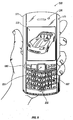
- Figure 5 illustrates a front view of a mobile communications device 500 in an unlocked mode.
- the device 500 may be configured to receive a signal to acquire image data via a camera 222 upon selection or depression of predefined keys in the keyboard 532 , upon selection or depression of one of the keys or buttons in a navigation row 580 or upon actuation or depression of a cursor navigation tool 527 .
- the device 500 comprises a microphone 236 that can be configured to cooperate with an audio recorder 223 to acquire sound data.
- Figure 6 illustrates a back view of a mobile communications device 500 comprising a flash 605 and side buttons 601 .
- a mobile communications device can be configured so as to receive a signal, to acquire image data, or take a photograph, upon the depression or the selection of one or more of the side buttons 601 .
- Figure 7 illustrates a locked mobile communications device 500 within this technology.
- the device 500 in Figure 7 can be said to be in a locked mode.
- the display 222 of the device 500 shows a device locked menu.
- the device locked menu 701 comprises three selectable options: unlock, emergency call, and cancel. If unlock is selected, the display 222 will display an input screen to accept entry of a predetermined password. If emergency call is selected, the display 222 will display an input screen to accept allow confirmation that an emergency call is to be placed. If an emergency call is confirmed as desired, an emergency call will be placed according to preconfigured settings and programming of the device 500 .
- a mobile communications device 500 can be configured to receive input to perform a locked function 304 , such as taking a photograph.
- a mobile communications device can be configured so as to receive a signal, to acquire image data, or take a photograph, upon the depression or the selection of one or more of the side buttons 601 .
- the locked device 500 may be configured to receive a signal to acquire image data via a camera 222 upon selection or depression of predefined keys in the keyboard 532 , upon selection or depression of one of the keys or buttons in a navigation row 580 or upon actuation or depression of a cursor navigation tool 527 .
- Figure 8 illustrates an exemplary implementation of a display 222 portion of a mobile communications device 500 that is in a locked mode.
- a lock menu 701 is displayed on the display 222 .
- the device locked menu 701 comprises four selectable options: unlock, camera, emergency call, and cancel. Selection of the camera option can comprise the inputting of a request to acquire image data or take a photograph.
- Figure 9 illustrates an exemplary implementation of a display 222 portion of a mobile communications device 500 that is in a locked mode.
- the display 222 provides an unlock control menu listing two options: device and camera. If device is selected, a list of selectable locked functions within this technology can be presented. Alternatively, and depending on the manner in which the mobile communications device 500 is configured according to the technology, if device is selected, the performance of a predefined locked function, such as acquisition of sound data via a microphone 236 or an audio recorder 223 or a microphone 236 and an audio recorder 223 can be implemented according to the technology.
- a predefined locked function such as acquisition of sound data via a microphone 236 or an audio recorder 223 or a microphone 236 and an audio recorder 223 can be implemented according to the technology.
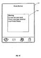
- Figure 10 illustrates an exemplary display 222 of a mobile communications device 500 that displays an example of a locked function usage message 1001 .
- the device 500 can be configured within this technology to present a message to an authorized user that a locked function has been used or enabled.
- the display 222 presents information regarding where data acquired during a locked mode of the device 500, has been stored.
- the device 500 can further be configured to display the amount of locked device usage remaining.
- the display 222 can be configured to present the number of photographs which may still be acquired while in the locked mode.
- the display 222 can be configured to display the amount of time remaining in which a locked function may be performed.
- a mobile communications device 500 can be configured to limit the amount of time in which one or more locked functions can be performed. This can be implemented by maintaining a time calculator for determining the amount of time that has elapsed after a specified event.
- An example of a specified event within this technology is a specified performance of locked function.
- An example of a specified performance of a locked function is a first performance of a locked function.
- An example of first performance of a locked function within the technology could be the first time image data is acquired since the last time the device 500 was unlocked via a password.
- a mobile communications device 500 can be configured to maintain a locked usage accumulator and time calculator for determining an amount of lapsed time such that usage of one or more locked functions can be limited to both a predetermined limit of usage and a predetermined amount of time.
- a mobile communications device 500 can be configured to maintain a locked function usage accumulator, while also maintain in a time calculator.
- the locked function usage accumulator can comprise a current value and a predetermined limit.
- a device 500 can be configured to receive input to perform a locked function, such as the depression of a predetermined button or selection of a predetermined menu option, compare the accumulator current value to the predetermined limit and perform the locked function when the accumulator is less than the predetermined limit.
- a mobile communications device 500 can be further configured to increment the accumulator current value upon performing the locked function and to maintain a time calculator for determining an amount of elapsed time.
- the device 500 can be further configured to lock the mobile communications device 500 after a predetermined amount of time has elapsed since a specified event.
- a mobile communications device 500 can be configured or programmed send an email notification via a network 124 to an authorized user's email address notifying him or her that a locked function, such as the acquisition of image data via a device camera 221 , has occurred.
- a device 500 may be configured to display a message 1001 on the device display 221 regarding the performance of one or more locked functions. An example of the presentation of such a message is depicted in Figure 10 .
- the technology can take the forms of hardware, or both hardware and software elements.
- the technology is implemented in software, which includes but is not limited to firmware, resident software, microcode, a Field Programmable Gate Array (FPGA) or Application-Specific Integrated Circuit (ASIC), etc.
- FPGA Field Programmable Gate Array
- ASIC Application-Specific Integrated Circuit
- a computer-usable or computer readable medium can be any apparatus that can contain, store, communicate, propagate, or transport the program for use by or in connection with the instruction execution system, apparatus, or device 500 .
- the medium can be an electronic, magnetic, optical, electromagnetic, infrared, or semiconductor system (or apparatus or device 500 ) or a propagation medium (though propagation mediums as signal carriers per se are not included in the definition of physical computer-readable medium).
- Examples of a physical computer-readable medium include a semiconductor or solid state memory, removable memory connected via USB, magnetic tape, a removable computer diskette, a random access memory (RAM), a read-only memory (ROM), a rigid magnetic disk and an optical disk.
- Current examples of optical disks include compact disk - read only memory (CD-ROM), compact disk - read/write (CD-R/W), DVD, and Blu Ray TM .
- processors and program code for implementing each as aspect of the technology can be centralized or distributed (or a combination thereof).
- a computer-usable or computer readable medium can be any apparatus that can contain, store, communicate, propagate, or transport the program for use by or in connection with the instruction execution system, apparatus, or device 500 .
- the medium can be an electronic, magnetic, optical, electromagnetic, infrared, or semiconductor system (or apparatus or device 500 ) or a propagation medium (though propagation mediums as signal carriers per se are not included in the definition of physical computer-readable medium).
- Examples of a physical computer-readable medium include a semiconductor or solid state memory, magnetic tape, a removable computer diskette, a random access memory (RAM), a read-only memory (ROM), a rigid magnetic disk and an optical disk.
- Current examples of optical disks include compact disk - read only memory (CD-ROM), compact disk - read/write (CD-R/W) and DVD.
- processors and program code for implementing each as aspect of the technology can be centralized or distributed (or a combination thereof).
- a data processing system suitable for storing a computer program product of the present technology and for executing the program code of the computer program product will include at least one processor coupled directly or indirectly to memory elements through a system bus.
- the memory elements can include local memory employed during actual execution of the program code, bulk storage, and cache memories that provide temporary storage of at least some program code in order to reduce the number of times code must be retrieved from bulk storage during execution.
- I/O devices including but not limited to keyboards, displays, pointing devices, etc.
- Network adapters can also be coupled to the system to enable the data processing system to become coupled to other data processing systems or remote printers or storage devices through intervening private or public networks.
- Modems, cable modem, WiFi, and Ethernet cards are just a few of the currently available types of network adapters.
- Such systems can be centralized or distributed, e.g., in peer-to-peer and client/server configurations.
- the data processing system is implemented using one or both of FPGAs and ASICs.
Description
- The present disclosure relates generally to mobile communications devices. More specifically, enabling implementations relate to mobile communications devices having a lock mode that can be bypassed and incorporating a camera assembly. The technology provides means and methods whereby a camera assembly in a mobile communications device may be utilized under certain conditions without compromising security of the mobile communications device. The technology extends the functionality of device applications in a secure manner. In at least one implementation, the technology provides for the temporary utilization of one or more mobile communication device applications without the inputting of an otherwise required password. The technology can be customized dynamically on a per device basis.
-
WO03/075585 - Aspects of the invention are disclosed in the accompanying claims.
-
-
FIG. 1 illustrates a communication system including a mobile communications device to which example implementations of the technology can be applied. -
FIG. 2 illustrates a block diagram of a mobile communications device. -
Fig. 3 illustrates the steps of an exemplary method within the technology. -
FIG. 4 illustrates the steps of an exemplary method within the technology. -
FIG. 5 illustrates a front view of a mobile communications device to which example implementations of the technology can be applied. -
FIG. 6 illustrates a rear view of a mobile communications device to which example implementations of the technology can be applied. -
Fig. 7 illustrates an implementation of a front view of a mobile communications device with a display displaying device options. -
FIG. 8 illustrates a first alternative implementation of a mobile communications device display displaying alternative display options. -
FIG.9 illustrates a second alternative implementation of a mobile communications device display displaying alternative display options. -
FIG. 10 illustrates a mobile communications device display displaying an exemplary notification within the technology. - Reference will now be made in detail to implementations of the technology. Each example is provided by way of explanation of the technology only, not as a limitation of the technology. It will be apparent to those skilled in the art that various modifications and variations can be made in the present technology. For instance, features described as part of one implementation of the technology can be used on another implementation to yield a still further implementation. Thus, it is intended that the present technology cover such modifications and variations that come within the scope of the technology.
- In order to facilitate an understanding of environments in which example implementations described herein can operate, reference is made to
FIG. 1 , which shows, in block diagram form, acommunication system 100 in which implementations of the technology can be applied. Thecommunication system 100 may comprise a number ofmobile communications devices 103 that may be connected to the remainder ofsystem 100 in any of several different ways. Accordingly, several instances ofmobile communications devices 103 are depicted inFIG. 1 employing different example ways of connecting tosystem 100. - These figures are exemplary only, and those persons skilled in the art will appreciate that additional elements and modifications may be necessary to make the communications device, e.g., 103 operable in particular network environments. While in the illustrated implementations, the communication devices, e.g., 103 may comprise smart phones, in other implementations, the communications devices may comprise personal digital assistants (PDA), tablet computers, laptop computers, desktop computers, servers, or other communications devices capable of sending and receiving electronic messages.
-
Mobile communications devices 103 are connected to awireless network 101 that may comprise one or more of a Wireless Wide Area Network (WWAN) 102 and a Wireless Local Area Network (WLAN) 104 or other suitable network arrangements. In some implementations, themobile communications devices 103 are configured to communicate over both the WWAN 102 and WLAN 104, and to roam between these networks. In some implementations, thewireless network 101 may comprise multiple WWANs 102 andWLANs 104. - The WWAN 102 may be implemented as any suitable wireless access network technology. By way of example, but not limitation, the WWAN 102 may be implemented as a wireless network that includes a number of
transceiver base stations 108 where each of thebase stations 108 provides wireless Radio Frequency (RF) coverage to a corresponding area or cell. The WWAN 102 is typically operated by a mobile network service provider that provides subscription packages to users of themobile communications devices 103. In some implementations, the WWAN 102 conforms to one or more of the following wireless network types: Mobitex Radio Network, DataTAC, GSM (Global System for Mobile Communication), GPRS (General Packet Radio System), TDMA (Time Division Multiple Access), CDMA (Code Division Multiple Access), CDPD (Cellular Digital Packet Data), iDEN (integrated Digital Enhanced Network), EvDO (Evolution-Data Optimized) CDMA2000, EDGE (Enhanced Data rates for GSM Evolution), UMTS (Universal Mobile Telecommunication Systems), HSPDA (High-Speed Downlink Packet Access), IEEE 802.16e (also referred to as Worldwide Interoperability for Microwave Access or "WiMAX"), or various other networks. Although WWAN 102 is described as a "Wide-Area" network, that term is intended herein also to incorporate wireless Metropolitan Area Networks (WMAN) and other similar technologies for providing coordinated service wirelessly over an area larger than that covered by typical WLANS. - The WWAN 102 may further comprise a
wireless network gateway 110 that connects themobile communications devices 103 totransport facilities 112, and through thetransport facilities 112 to awireless connector system 120. Transport facilities may include one or more private networks or lines, the Internet, a virtual private network, or any other suitable network. Thewireless connector system 120 may be operated, for example, by an organization or enterprise such as a corporation, university, or governmental department, which allows access to anetwork 124 such as an internal or enterprise network (e.g., an intranet), and its resources, or thewireless connector system 120 may be operated by a mobile network provider. In some implementations, thenetwork 124 may be realized using the Internet rather than, or in addition to, an internal or enterprise network. - The
wireless network gateway 110 provides an interface between thewireless connector system 120 and the WWAN 102, which facilitates communication between themobile communications devices 103 and other devices (not shown) connected, directly or indirectly, to the WWAN 102. Accordingly, communications sent via themobile communications devices 103 are transported via the WWAN 102 and thewireless network gateway 110 throughtransport facilities 112 to thewireless connector system 120. Communications sent from thewireless connector system 120 are received by thewireless network gateway 110 and transported via the WWAN 102 to themobile communications devices 103. - The WLAN 104 comprises a wireless network that, in some implementations, conforms to IEEE 802.11x standards (sometimes referred to as Wi-Fi TM) such as, for example, the IEEE 802.11a, 802.11b and/or 802.11g standard. Other communication protocols may be used for the WLAN 104 in other implementations such as, for example, IEEE 802.11n, IEEE 802.16e (also referred to as Worldwide Interoperability for Microwave Access or "WiMAX"), or IEEE 802.20 (also referred to as Mobile Wireless Broadband Access). The
WLAN 104 includes one or more wireless RF Access Points (AP) 114 (one of which is shown inFIG. 1 ) that collectively provide a WLAN coverage area. - The WLAN 104 may be a personal network of the user, an enterprise network, or a hotspot offered by an internet service provider (ISP), a mobile network provider, or a property owner in a public or semi-public area, for example. The
access pints 114 are connected to an access point (AP)interface 116 that may connect to thewireless connector system 120 directly, (for example, if theaccess point 114 is part of an enterprise WLAN 104 in which thewireless connector system 120 resides), or indirectly, as indicated by the dashed line inFIG. 1 , via thetransport facilities 112 if theaccess point 114 is a personal Wi-Fi network or Wi-Fi hotspot (in which case a mechanism for securely connecting to thewireless connector system 120, such as a virtual private network (VPN), may be used). TheAP interface 116 provides translation and routing services between theaccess points 114 and thewireless connector system 120 to facilitate communication, directly or indirectly, with thewireless connector system 120. - The
wireless connector system 120 may be implemented as one or more servers, and is typically located behind afirewall 113. Thewireless connector system 120 manages communications, including email, Hypertext Transfer Protocol (HTTP), and HTTP Secure (HTTPS) communications to and from a set of managedmobile communications devices 103. Thewireless connector system 120 also provides administrative control and management capabilities over users andmobile communications devices 103 that might connect to thewireless connector system 120. - The
wireless connector system 120 allows themobile communications devices 103 to access thenetwork 124 and connected resources and services such as a messaging server 132 (for example, a Microsoft Exchange Server®, IBM Lotus Domino®, or Novel GroupWise™ email server), acontent server 134 for providing content such as Internet content or content from an organization's internal servers,application servers 136 for implementing server-based applications such as instant messaging (IM) applications tomobile communications devices 103, and intranet file services. - The
wireless connector system 120 typically provides a secure exchange of data (e.g., email messages, personal information manager (PIM) data, and IM data) with themobile communications devices 103. In some implementations, communications between thewireless connector system 120 and themobile communications devices 103 are encrypted. In some implementations, communications are encrypted using a symmetric encryption key implemented using Advanced Encryption Standard (AES) or Triple Data Encryption Standard (Triple DES) encryption. Private encryption keys are generated in a secure, two-way authenticated environment and are used for both encryption and decryption of data. In some implementations, the private encryption key is stored only in the user's mailbox on themessaging server 132 and on themobile communications device 103, and can typically be regenerated by the user onmobile communications devices 103. Data sent to themobile communications devices 103 is encrypted by thewireless connector system 120 using the private encryption key retrieved from the user's mailbox. The encrypted data, when received on themobile communications devices 103, is decrypted using the private encryption key stored in memory. Similarly, data sent to thewireless connector system 120 from themobile communications devices 103 is encrypted using the private encryption key stored in the memory of themobile communications device 103. The encrypted data, when received on thewireless connector system 120, is decrypted using the private encryption key retrieved from the user's mailbox. - The
wireless network gateway 110 is adapted to send data packets received from themobile communications device 103 over theWWAN 102 to thewireless connector system 120. Thewireless connector system 120 then sends the data packets to the appropriate connection point such as themessaging server 132 orcontent servers 134 orapplication server 136. Conversely, thewireless connector system 120 sends data packets received, for example, from themessaging server 132 orcontent servers 134 orapplication servers 136 to thewireless network gateway 110 that then transmit the data packets to the destinationmobile communications device 103. The AP interfaces 116 of theWLAN 104 provide similar sending functions between themobile communications device 103, thewireless connector system 120 and network connection point such as themessaging server 132,content server 134 andapplication server 136. - The
network 124 may comprise a private local area network, metropolitan area network, wide area network, the public Internet or combinations thereof and may include virtual networks constructed using any of these, alone, or in combination. Amobile communications device 103 may alternatively connect to thewireless connector system 120 using acomputer 117, such as desktop or notebook computer, via thenetwork 124. Alink 106 may be provided for exchanging information between themobile communications device 103 and acomputer 117 connected to thewireless connector system 120. Thelink 106 may comprise one or both of a physical interface and short-range wireless communication interface. The physical interface may comprise one or combinations of an Ethernet connection, Universal Serial Bus (USB) connection, Firewire™ (also known as an IEEE 1394 interface) connection, or other serial data connection, via respective ports or interfaces of themobile communications device 103 andcomputer 117. The short-range wireless communication interface may be a personal area network (PAN) interface. A Personal Area Network is a wireless point-to-point connection meaning no physical cables are used to connect the two end points. The short-range wireless communication interface may comprise one or a combination of an infrared (IR) connection such as an Infrared Data Association (IrDA) connection, a short-range radio frequency (RF) connection such as one specified by IEEE 802.15.1 or the BLUETOOTH special interest group, or IEEE 802.15.3a, also referred to as UltraWideband (UWB), or other PAN connection. - It will be appreciated that the above-described communication system is provided for the purpose of illustration only, and that the above-described communication system comprises one possible communication network configuration of a multitude of possible configurations for use with the
mobile communications devices 103. Suitable variations of the communication system will be understood to a person of skill in the art and are intended to fall within the scope of the present disclosure. - As will be appreciated from
FIG. 5 , an exemplary mobile communications device 500 (as an example of 103) comprises adisplay 222 located above akeyboard 232 constituting a user input means that is suitable for accommodating textual input to thedevice 500. In some implementations, thekeyboard 232 can be part of a touch screen display 522. Thefront face 570 of thedevice 500 has anavigation row 580. As shown, thedevice 500 is of uni-body construction, also known as a "candy-bar" design. - The
device 500 may include an auxiliary input that acts as acursor navigation tool 527 and that may be also exteriorly located upon thefront face 570 of thedevice 500. The front face location of acursor navigation tool 527 allows the tool to be thumb-actuable, e.g., like the keys of thekeyboard 232. Some implementations of the technology provide thenavigation tool 527 in the form of a trackball (not shown) that may be utilized to instruct two-dimensional screen cursor movement in substantially any direction, as well as act as an actuator when the trackball is depressed like a button. Other implementations can provide the navigation tool in the form of a trackpad, a touchpad, a pointing stick, joystick, graphics tablet, or combinations thereof. The placement of thenavigation tool 527 can be above thekeyboard 232 and below thedisplay 222; here, it may avoid interference during keyboarding and does not block the operator's view of thedisplay 222 during use. - The
device 500 may be configured to send and receive messages. Thedevice 500 includes abody 571 that can, in some implementations, be configured to be held in one hand by an operator of thedevice 500 during text entry. Adisplay 222 is included that is located on afront face 570 of thebody 571 and upon which information is displayed to the operator, e.g., during text entry. Thedevice 500 may also be configured to send and receive voice communications such as mobile telephone calls. Thedevice 500 also can include acamera 221 to allow thedevice 500 to take electronic photographs that can be referred to as photos or pictures or image data. Thedevice 500 can include anaudio recorder 223 that can be incorporated into amicrophone 236 or can be separated from amicrophone 236. Further, thedevice 500 can be configured to operate a web browser. - The
device 500 may further contain a sensor, e.g., proximity sensor, behind a cover mounted in an aperture defined inbody 571. In devices where substantially all thefront face 570 of the device is a touch screen, a portion of the touch screen can constitute the cover. - Referring to
FIG. 2 , a block diagram of a communications device, such as 500 and 103, in accordance with an exemplary implementation is illustrated. As shown, thedevice 500 includes aprocessor 238 that controls the operation of thecommunications device 500. Acommunication subsystem 211 performs communication transmission and reception with thewireless network 219. Themicroprocessor 238 further can be communicatively coupled with an auxiliary input/output (I/O) subsystem 228. In at least one implementation, theprocessor 238 can be communicatively coupled to a serial port (for example, a Universal Serial Bus port) 230 that can allow for communication with other devices or systems via theserial port 230. Adisplay 222 can be communicatively coupled toprocessor 238 to allow for display of information to an operator of thecommunications device 500. When thecommunications device 500 is equipped with akeyboard 232, the keyboard can also be communicatively coupled with theprocessor 238. Thecommunications device 500 can include aspeaker 234, amicrophone 236, random access memory (RAM) 226, andflash memory 224, all of which may be communicatively coupled to theprocessor 238. Other similar components may be provided on thecommunications device 500 as well and optionally communicatively coupled to theprocessor 238.Other communication subsystems 240 andother device subsystems 242 are generally indicated as being functionally connected with theprocessor 238 as well. An example of acommunication subsystem 240 is a short range communication system such as BLUETOOTH® communication module or a WI-FI® communication module (a communication module in compliance with IEEE 802.11b) and associated circuits and components. Examples ofother device subsystem 242 include a sensor and implementations of the present technology. - Additionally, the
processor 238 is able to perform operating system functions and enables execution of programs on thecommunications device 500. In some implementations not all of the above components are included in thecommunications device 500. For example, in at least one implementation, thekeyboard 232 is not provided as a separate component and is instead integrated with a touch screen as described below. - The auxiliary I/O subsystem 228 can take the form of a variety of different navigation tools (multi-directional or single-directional) such as a
trackball navigation tool 521, as illustrated in the exemplary implementation shown inFIG. 5 , or a thumbwheel, a navigation pad, a joystick, touch-sensitive interface, or other I/O interface. These navigation tools may be located on the front surface of thecommunications device 500 or may be located on any exterior surface of thecommunications device 500. Other auxiliary I/O subsystems may include external display devices and externally connected keyboards (not shown). While the above examples have been provided in relation to the auxiliary I/O subsystem 228, other subsystems capable of providing input or receiving output from thecommunications device 500 are considered within the scope of this disclosure. Additionally, other keys may be placed along the side of thecommunications device 500 to function as escape keys, volume control keys, scrolling keys, power switches, or user programmable keys, and may likewise be programmed accordingly. - The
keyboard 232 can include a plurality of keys that can be of a physical nature such as actuable buttons, or the actuable buttons can be of a software nature, typically constituted by representations of physical keys on a display 222 (referred to herein as "virtual keys"). It is also contemplated that the user input can be provided as a combination of the two types of keys. Each key of the plurality of keys is associated with at least one action that can be the input of a character, a command or a function. In this context, "characters" are contemplated to exemplarily include alphabetic letters, language symbols, numbers, punctuation, insignias, icons, pictures, and even a blank space. - In the case of virtual keys, the indicia for the respective keys are shown on the
display 222, which in one implementation is enabled by touching thedisplay 222, for example, with a stylus, finger, finger tip, finger nail, or other pointer, to generate the character or activate the indicated command or function. Some examples ofdisplays 222 capable of detecting a touch include resistive, capacitive, projected capacitive, infrared and surface acoustic wave (SAW) touch screens. - Physical and virtual keys can be combined in many different ways as appreciated by those skilled in the art. In one implementation, physical and virtual keys are combined such that the plurality of enabled keys for a particular program or feature of the
communications device 500 is shown on thedisplay 222 in the same configuration as the physical keys. Using this configuration, the operator can select the appropriate physical key corresponding to what is shown on thedisplay 222. Thus, the desired character, command or function is obtained by depressing the physical key corresponding to the character, command or function displayed at a corresponding position on thedisplay 222, rather than touching thedisplay 222. - Furthermore, the
communications device 500 is equipped with components to enable operation of various programs, as shown inFIG. 2 . In an exemplary implementation, theflash memory 224 is enabled to provide a storage location for theoperating system 257,device programs 258, and data. Theoperating system 257 is generally configured to manageother programs 258 that are also stored inmemory 224 and executable on theprocessor 238. Theoperating system 257 honors requests for services made byprograms 258 through predefined program interfaces. More specifically, theoperating system 257 typically determines the order in whichmultiple programs 258 are executed on theprocessor 238 and the execution time allotted for eachprogram 258, manages the sharing ofmemory 224 amongmultiple programs 258, handles input and output to and fromother device subsystems 242, and so on. In addition, operators typically can interact directly with theoperating system 257 through a user interface usually including thekeyboard 232 anddisplay 222. While in an exemplary implementation theoperating system 257 is stored inflash memory 224, theoperating system 257 in other implementations is stored in read-only memory (ROM) or similar storage element (not shown). As those skilled in the art will appreciate, theoperating system 257,device program 258, or parts thereof, may be loaded inRAM 226 or other volatile memory. - In some implementations, the
flash memory 224 may containprograms 258 for execution on thedevice 500, including - but not limited to - anaddress book 252, a personal information manager (PIM) 254, and adevice state 250. Furthermore,programs 258, such as social software, andother information 256 including data can be segregated upon storage in theflash memory 224 of thedevice 500. - When the
communications device 500 is enabled for two-way communication within the wireless communication network 219 (e.g., 108), it can send and receive signals from a mobile communication service. Examples of communication systems enabled for two-way communication include, but are not limited to, the General Packet Radio Service (GPRS) network, the Universal Mobile Telecommunication Service (UMTS) network, the Enhanced Data for Global Evolution (EDGE) network, the Code Division Multiple Access (CDMA) network, High-Speed Packet Access (HSPA) networks, Universal Mobile Telecommunication Service Time Division Duplexing (UMTS-T9), Ultra Mobile Broadband (UMB) networks, Worldwide Interoperability for Microwave Access (WiMAX), and other networks that can be used for data and voice, or just data or voice. For the systems listed above, thecommunications device 500 may use a unique identifier to enable thecommunications device 500 to transmit and receive signals from thecommunication network 219. Other systems may not use such identifying information. GPRS, UMTS, and EDGE use a Subscriber Identity Module (SIM) in order to allow communication with thecommunication network 219. Likewise, most CDMA systems use a Removable User Identity Module (RUIM) in order to communicate with the CDMA network. The RUIM and SIM card can be used in multipledifferent communications devices 500. Acommunications device 500 can be configured to operate some features without a SIM/RUIM card, but a communications device will not necessarily be able to communicate with thenetwork 219. A SIM/RUIM interface 244 located within thecommunications device 500 allows for removal or insertion of a SIM/RUIM card (not shown). The SIM/RUIM card features memory and holdskey configurations 251, andother information 253 such as identification and subscriber related information. With a properly enabledcommunications device 500, two-way communication between thecommunications device 500 andcommunication network 219 is possible. - If the
communications device 500 is enabled as described above or thecommunication network 219 does not use such enablement, the two-way communication enabledcommunications device 500 is able to both transmit and receive information from thecommunication network 219. The transfer of communication can be from thecommunications device 500 or to thecommunications device 500. In order to communicate with thecommunication network 219, thedevice 500 can be equipped with an integral orinternal antenna 218 for transmitting signals to thecommunication network 219. Likewise thedevice 500 can be equipped with anotherantenna 216 for receiving communication from thecommunication network 219. These antennae (216, 218) in another exemplary implementation are combined into a single antenna (not shown). As one skilled in the art would appreciate, the antenna or antennae (216, 218) in another implementation can be externally mounted on thecommunications device 500. - When equipped for two-way communication, the
communications device 500 features acommunication subsystem 211. As is understood in the art, acommunication subsystem 211 is modified so that a communication subsystem can support the operational needs of acommunications device 500. Thesubsystem 211 includes atransmitter 214 andreceiver 212 including the associated antenna or antennae (216, 218) as described above, local oscillators (LOs) 213, and a processing module that in the presently described exemplary implementation is a digital signal processor (DSP) 220. - It is contemplated that communication by the
communications device 500 with thewireless network 219 can be any type of communication that both thewireless network 219 andcommunications device 500 are enabled to transmit, receive and process. In general, these can be classified as voice or data, or both voice and data. Voice communication generally refers to communication in which signals for audible sounds are transmitted by thecommunications device 500 through thecommunication network 219. Data generally refers to all other types of communication that thecommunications device 500 is capable of performing within the constraints of thewireless network 219. - Example device programs that can depend on such data include email, contacts and calendars. For each such program, synchronization with home-based versions of the program can be desirable for either or both of the long term utility of device programs and the short term utility of device programs. As an example, emails are often time-sensitive, so substantially real time (or near-real time) synchronization may be desired. Contacts, on the other hand, can be usually updated less frequently without inconvenience. Therefore, the utility of the
communications device 500 is enhanced when connectable within a communication system, and when connectable on a wireless basis in anetwork 219 in which voice, text messaging, and other data transfer are accommodated.Device 500 can include programs such as a web browser, a file browser, and client programs for interacting with server programs. Devices, e.g., 103, 500, for use in the technology can be characterized by an identification number assigned to the device. Such identification numbers cannot be changed and are locked to each device. - Implementations of the technology can be realized as including programming on a mobile communications device, e.g., 103. In some implementations, programming for the technology is on the
mobile communications device 103, while data used by themobile communications device 103 is on thewireless connector system 120 or a network server such ascontent server 134,messaging server 132, orapplication server 136. In some implementations, programming for the technology can be realized on a remote server. Allocation of functionality among architectural elements can be a function of several factors including latency, processing resource availability and efficient usage, storage availability and efficient usage, and revenue opportunities. - In at least one implementation of the technology, in order to protect against unauthorized use, a mobile communications device can be locked such that a password or text must be entered via a
keyboard 232 before device applications are enabled. A lockeddevice 500 can be described as being in a locked mode. Situations can arise however, where it may be advantageous for certain device applications to be enabled even when a mobile communications device is in a locked mode. One example is the situation in which a user desires to use thecamera 221 of thedevice 500 without having to enter a password. A situation in which a user desires to use thecamera 221 of thedevice 500 without entering a password could occur, for example, when, during the time it would take to enter a password, the opportunity to take a photograph of a subject might pass. For example, a user who otherwise had not planned to take a photograph might observe a subject and desire to take a photograph quickly. - In some implementations of the technology, a mobile communications device comprises a locked function usage accumulator. The locked function usage accumulator comprises a current value and a predetermined limit. As examples, the predetermined limit may correspond to a number of photographs or a number of images. In this example, the locked function usage accumulator keeps track of the number of acquired images or stored images as the current value and the number of acquired images or stored images is compared to the predetermined limit. The current value can be compared to predetermined limit. If the current value is less than the predetermined limit, then the locked function, such as acquisition of image data or taking a photograph, can be performed using the camera.
- In some implementations of the technology, the locked function usage accumulator comprises a current value and a predetermined limit. The predetermined limit may correspond to an amount of image data acquired or an amount of image data stored. In these implementations the locked function usage accumulator keeps track of the amount of image data acquired by the
device 500 or the amount of image data stored by thedevice 500 as the current value, and the amount of image data acquired or the amount of image data stored is compared to the predetermined limit. If the current value is less than the predetermined limit, then the locked function, in this example, acquisition of image data or taking a photograph, can be performed using thecamera 221. -
Figure 3 illustrates the steps in a method within this technology that can implement the example described in the preceding paragraph. Amobile communications device 500 is configured to maintain a lockedfunction accumulator 302. The mobile communications device receives input to perform a lockedfunction 304. As examples, the input to perform a locked function may be the depression of a certain button on thedevice 500, for example a camera button, or the touching of a certain area on atouch screen display 222. The current value of the locked function usage accumulator is compared to the predetermined limit. If the current value of the locked function usage accumulator is less than the predetermined limit the locked function, for example the taking of a photograph, is performed. - The
mobile communications device 500 within this technology can increment the current value when a locked function occurs or is performed by thedevice 500. Thus, for example, adevice 500 can allow five photographs to be acquired while thedevice 500 is in a locked mode. The predetermined limit will therefore be understood to be five photographs or images. The current value is initially set to zero. Each time an image is acquired, the current value of the locked function usage accumulator is incremented by one. Each time thedevice 500 receives an input to perform a locked function, the current value (number of photographs taken), is compared to the predetermined limit of five photographs. Thus, when five photographs have been taken, the current value and the predetermined limit are equal. Thus, thedevice 500 will not perform the locked function because the current value comprised by the locked function usage accumulator is not less than the predetermined limit. -
Figure 4 illustrates the steps in a method within this technology that can implement the example described in the preceding paragraph. Amobile communications device 500 is configured to maintain a lockedfunction accumulator 302. The mobile communications device receives input to perform a lockedfunction 304. The input to perform a locked function can be e.g., the depression of a certain button on thedevice 500, for example a camera button, or the touching of a certain area on atouch screen display 222. The current value of the locked function usage accumulator is compared to thepredetermined limit 306. If the current value of the locked function usage accumulator is less than the predetermined limit the locked function, for example the taking of a photograph, is performed 308. In the method shown inFig. 4 , when a locked function, such as the acquisition of image data, is performed, the current value comprised by the locked function usage accumulator is incremented 410. - Within this technology, a predetermined limit can be a number of stored or acquired images, as described above, or a predetermined limit can be an amount of image data acquired or an amount of image data stored. A predetermined limit can be a percentage of available memory allocated for image data. A predetermined limit can also be a number of sound or audio recordings acquired or a number or sound or audio recordings stored. Acquired sound or audio recordings can be stored locally on the
device 500 or externally to thedevice 500, on anapplication server 136 or on acomputer 117, for example. A predetermined limit can further be an amount of sound or audio data. All examples listed in this description are non-limiting and do not exclude the implementation of the technology using other data types. -
Figure 5 illustrates a front view of amobile communications device 500 in an unlocked mode. Thedevice 500 may be configured to receive a signal to acquire image data via acamera 222 upon selection or depression of predefined keys in the keyboard 532, upon selection or depression of one of the keys or buttons in anavigation row 580 or upon actuation or depression of acursor navigation tool 527. Thedevice 500 comprises amicrophone 236 that can be configured to cooperate with anaudio recorder 223 to acquire sound data. -
Figure 6 illustrates a back view of amobile communications device 500 comprising aflash 605 andside buttons 601. A mobile communications device can be configured so as to receive a signal, to acquire image data, or take a photograph, upon the depression or the selection of one or more of theside buttons 601. -
Figure 7 illustrates a lockedmobile communications device 500 within this technology. Thedevice 500 inFigure 7 can be said to be in a locked mode. Thedisplay 222 of thedevice 500 shows a device locked menu. The device lockedmenu 701 comprises three selectable options: unlock, emergency call, and cancel. If unlock is selected, thedisplay 222 will display an input screen to accept entry of a predetermined password. If emergency call is selected, thedisplay 222 will display an input screen to accept allow confirmation that an emergency call is to be placed. If an emergency call is confirmed as desired, an emergency call will be placed according to preconfigured settings and programming of thedevice 500. As described above, amobile communications device 500 can be configured to receive input to perform a lockedfunction 304, such as taking a photograph. A mobile communications device can be configured so as to receive a signal, to acquire image data, or take a photograph, upon the depression or the selection of one or more of theside buttons 601. The lockeddevice 500 may be configured to receive a signal to acquire image data via acamera 222 upon selection or depression of predefined keys in the keyboard 532, upon selection or depression of one of the keys or buttons in anavigation row 580 or upon actuation or depression of acursor navigation tool 527. -
Figure 8 illustrates an exemplary implementation of adisplay 222 portion of amobile communications device 500 that is in a locked mode. In the implementation illustrated inFigure 8 , alock menu 701 is displayed on thedisplay 222. The device lockedmenu 701 comprises four selectable options: unlock, camera, emergency call, and cancel. Selection of the camera option can comprise the inputting of a request to acquire image data or take a photograph. -
Figure 9 illustrates an exemplary implementation of adisplay 222 portion of amobile communications device 500 that is in a locked mode. Thedisplay 222 provides an unlock control menu listing two options: device and camera. If device is selected, a list of selectable locked functions within this technology can be presented. Alternatively, and depending on the manner in which themobile communications device 500 is configured according to the technology, if device is selected, the performance of a predefined locked function, such as acquisition of sound data via amicrophone 236 or anaudio recorder 223 or amicrophone 236 and anaudio recorder 223 can be implemented according to the technology. -
Figure 10 illustrates anexemplary display 222 of amobile communications device 500 that displays an example of a lockedfunction usage message 1001. Thedevice 500 can be configured within this technology to present a message to an authorized user that a locked function has been used or enabled. In the implementation shown inFigure 10 , thedisplay 222 presents information regarding where data acquired during a locked mode of thedevice 500, has been stored. - The
device 500 can further be configured to display the amount of locked device usage remaining. For example thedisplay 222 can be configured to present the number of photographs which may still be acquired while in the locked mode. Thedisplay 222 can be configured to display the amount of time remaining in which a locked function may be performed. - Within the technology; a
mobile communications device 500 can be configured to limit the amount of time in which one or more locked functions can be performed. This can be implemented by maintaining a time calculator for determining the amount of time that has elapsed after a specified event. An example of a specified event within this technology is a specified performance of locked function. An example of a specified performance of a locked function is a first performance of a locked function. An example of first performance of a locked function within the technology could be the first time image data is acquired since the last time thedevice 500 was unlocked via a password. - In further implementations of the technology, a
mobile communications device 500 can be configured to maintain a locked usage accumulator and time calculator for determining an amount of lapsed time such that usage of one or more locked functions can be limited to both a predetermined limit of usage and a predetermined amount of time. - To limit usage of one or more locked functions according to both amount of locked device usage and an amount of time, whether the limit is acquisition of a predetermined number of photo images, a predetermined amount of image data acquired or stored, a predetermined number of sound recordings, or a predetermined amount of sound data acquired or stored, or some other limit, a
mobile communications device 500 can be configured to maintain a locked function usage accumulator, while also maintain in a time calculator. The locked function usage accumulator can comprise a current value and a predetermined limit. Adevice 500 can be configured to receive input to perform a locked function, such as the depression of a predetermined button or selection of a predetermined menu option, compare the accumulator current value to the predetermined limit and perform the locked function when the accumulator is less than the predetermined limit. As described above, amobile communications device 500 can be further configured to increment the accumulator current value upon performing the locked function and to maintain a time calculator for determining an amount of elapsed time. Thedevice 500 can be further configured to lock themobile communications device 500 after a predetermined amount of time has elapsed since a specified event. - Within the technology, a
mobile communications device 500 can be configured or programmed send an email notification via anetwork 124 to an authorized user's email address notifying him or her that a locked function, such as the acquisition of image data via adevice camera 221, has occurred. In a further implementation of the technology, adevice 500 may be configured to display amessage 1001 on thedevice display 221 regarding the performance of one or more locked functions. An example of the presentation of such a message is depicted inFigure 10 . - The technology can take the forms of hardware, or both hardware and software elements. In some implementations, the technology is implemented in software, which includes but is not limited to firmware, resident software, microcode, a Field Programmable Gate Array (FPGA) or Application-Specific Integrated Circuit (ASIC), etc. In particular, for real-time or near real-time use, an FPGA or ASIC implementation is desirable.
- Furthermore, the present technology can take the form of a computer program product comprising program modules accessible from computer-usable or computer-readable medium storing program code for use by or in connection with one or more computers, processors, or instruction execution system. For the purposes of this description, a computer-usable or computer readable medium can be any apparatus that can contain, store, communicate, propagate, or transport the program for use by or in connection with the instruction execution system, apparatus, or
device 500. The medium can be an electronic, magnetic, optical, electromagnetic, infrared, or semiconductor system (or apparatus or device 500) or a propagation medium (though propagation mediums as signal carriers per se are not included in the definition of physical computer-readable medium). Examples of a physical computer-readable medium include a semiconductor or solid state memory, removable memory connected via USB, magnetic tape, a removable computer diskette, a random access memory (RAM), a read-only memory (ROM), a rigid magnetic disk and an optical disk. Current examples of optical disks include compact disk - read only memory (CD-ROM), compact disk - read/write (CD-R/W), DVD, and Blu Ray™. Both processors and program code for implementing each as aspect of the technology can be centralized or distributed (or a combination thereof). - Furthermore, the present technology can take the form of a computer program product comprising program modules accessible from computer-usable or computer-readable medium storing program code for use by or in connection with one or more computers, processors, or instruction execution system. For the purposes of this description, a computer-usable or computer readable medium can be any apparatus that can contain, store, communicate, propagate, or transport the program for use by or in connection with the instruction execution system, apparatus, or
device 500. The medium can be an electronic, magnetic, optical, electromagnetic, infrared, or semiconductor system (or apparatus or device 500) or a propagation medium (though propagation mediums as signal carriers per se are not included in the definition of physical computer-readable medium). Examples of a physical computer-readable medium include a semiconductor or solid state memory, magnetic tape, a removable computer diskette, a random access memory (RAM), a read-only memory (ROM), a rigid magnetic disk and an optical disk. Current examples of optical disks include compact disk - read only memory (CD-ROM), compact disk - read/write (CD-R/W) and DVD. Both processors and program code for implementing each as aspect of the technology can be centralized or distributed (or a combination thereof). - A data processing system suitable for storing a computer program product of the present technology and for executing the program code of the computer program product will include at least one processor coupled directly or indirectly to memory elements through a system bus. The memory elements can include local memory employed during actual execution of the program code, bulk storage, and cache memories that provide temporary storage of at least some program code in order to reduce the number of times code must be retrieved from bulk storage during execution. Input/output or I/O devices (including but not limited to keyboards, displays, pointing devices, etc.) can be coupled to the system either directly or through intervening I/O controllers. Network adapters can also be coupled to the system to enable the data processing system to become coupled to other data processing systems or remote printers or storage devices through intervening private or public networks. Modems, cable modem, WiFi, and Ethernet cards are just a few of the currently available types of network adapters. Such systems can be centralized or distributed, e.g., in peer-to-peer and client/server configurations. In some implementations, the data processing system is implemented using one or both of FPGAs and ASICs.
Claims (15)
- A computer program product for enabling limited access to a locked function in a mobile communications device (500), the computer program product comprising:a least one computer readable medium (224); andat least one program module, stored on the at least one medium (224), andoperative, upon execution by at least one processor (238) to: maintain a locked function usage accumulator, the locked function usage accumulator comprising a current value and a predetermined limit;receive input to perform a locked function when in a locked mode, compare the accumulator current value to the predetermined limit (306); and perform, when in the locked mode, the locked function when the accumulator is less than the predetermined limit (308); wherein the input comprises the associated function input; and wherein the locked function receives and stores image data or sound data.
- The computer program product of claim 1, the at least one program module further operative, upon execution by at least one processor to:increment the accumulator current value upon performing the locked function (410).
- The computer program product of claim 2, the at least one program module further operative, upon execution by at least one processor (238) to:maintain a time calculator for determining an amount of elapsed time; andlock the electronic device after a predetermined amount of time has elapsed since a specified event.
- The computer program product of claim 3, wherein the specified event is a first performance of the locked function.
- The computer program product of claim 3 or 4, wherein the locked function is a camera function.
- The computer program product of claim 3 or 4 or 5, wherein the locked function is a sound recorder function.
- A mobile communications device (500) comprising:at least one processor (238); anda computer program product according to claim 1;in communication with the processor (238);and stored on the at least one medium (224).
- The mobile communications device (500) of claim 7, the at least one program module operable, upon execution by the processor (238) to:increment the accumulator current value upon performing the locked function (410);maintain a time calculator for determining an amount of elapsed time; andlock the mobile communications device after a predetermined amount of time has elapsed since a specified event.
- A processor-implemented method for enabling limited access to a locked function in a mobile communications device (500), the method comprising:maintaining a locked function usage accumulator, the locked function usage accumulator comprising a current value and a predetermined limit;receiving input to perform a locked function when in a locked mode;comparing the accumulator current value to the predetermined limit (306); andperforming, when in the locked mode, the locked function when the accumulator is less than the predetermined limit (308); wherein the input comprises the associated function input; and wherein the locked function receives and stores image data or sound data.
- The processor-implemented method of claim 9, further comprising:incrementing the accumulator current value upon performing the locked function (410).
- The processor-implemented method of claim 9 or 10, further comprising:maintaining a time calculator for determining an amount of elapsed time; andlocking the electronic device after a predetermined amount of time has elapsed since a specified event.
- The processor-implemented method of claim 9 or 10 or 11, wherein the locked function is a camera function.
- The processor-implemented method of claim 9, wherein the locked function is a sound recorder function.
- The processor-implemented method of claim 9 or 10 or 11 or 12, wherein the predetermined limit is a number of images.
- The processor-implemented method of claim 9, wherein the predetermined value is a stored image data value.
Priority Applications (4)
| Application Number | Priority Date | Filing Date | Title |
|---|---|---|---|
| EP10189894.8A EP2451139B1 (en) | 2010-11-03 | 2010-11-03 | Access to locked functions |
| CA2753635A CA2753635C (en) | 2010-11-03 | 2011-09-30 | Access to locked functions |
| CN201110301730.1A CN102469213B (en) | 2010-11-03 | 2011-10-08 | Mobile communication device and method |
| HK12107973.2A HK1167282A1 (en) | 2010-11-03 | 2012-08-14 | Access to locked functions |
Applications Claiming Priority (1)
| Application Number | Priority Date | Filing Date | Title |
|---|---|---|---|
| EP10189894.8A EP2451139B1 (en) | 2010-11-03 | 2010-11-03 | Access to locked functions |
Publications (3)
| Publication Number | Publication Date |
|---|---|
| EP2451139A1 EP2451139A1 (en) | 2012-05-09 |
| EP2451139A9 EP2451139A9 (en) | 2013-02-13 |
| EP2451139B1 true EP2451139B1 (en) | 2015-01-07 |
Family
ID=43859670
Family Applications (1)
| Application Number | Title | Priority Date | Filing Date |
|---|---|---|---|
| EP10189894.8A Active EP2451139B1 (en) | 2010-11-03 | 2010-11-03 | Access to locked functions |
Country Status (4)
| Country | Link |
|---|---|
| EP (1) | EP2451139B1 (en) |
| CN (1) | CN102469213B (en) |
| CA (1) | CA2753635C (en) |
| HK (1) | HK1167282A1 (en) |
Families Citing this family (8)
| Publication number | Priority date | Publication date | Assignee | Title |
|---|---|---|---|---|
| US9880604B2 (en) | 2011-04-20 | 2018-01-30 | Microsoft Technology Licensing, Llc | Energy efficient location detection |
| US9363250B2 (en) | 2011-12-23 | 2016-06-07 | Microsoft Technology Licensing, Llc | Hub coordination service |
| US8874162B2 (en) | 2011-12-23 | 2014-10-28 | Microsoft Corporation | Mobile device safe driving |
| US20130305354A1 (en) | 2011-12-23 | 2013-11-14 | Microsoft Corporation | Restricted execution modes |
| US9230076B2 (en) * | 2012-08-30 | 2016-01-05 | Microsoft Technology Licensing, Llc | Mobile device child share |
| US9998866B2 (en) | 2013-06-14 | 2018-06-12 | Microsoft Technology Licensing, Llc | Detecting geo-fence events using varying confidence levels |
| US9820231B2 (en) | 2013-06-14 | 2017-11-14 | Microsoft Technology Licensing, Llc | Coalescing geo-fence events |
| US9940930B1 (en) * | 2016-12-07 | 2018-04-10 | Google Llc | Securing audio data |
Family Cites Families (4)
| Publication number | Priority date | Publication date | Assignee | Title |
|---|---|---|---|---|
| AU2002237465A1 (en) * | 2002-03-04 | 2003-09-16 | Nokia Corporation | Method for intermediate unlocking of a keypad on a mobile electronic device |
| JP4471898B2 (en) * | 2005-07-22 | 2010-06-02 | シャープ株式会社 | Portable information terminal device |
| US20080254767A1 (en) * | 2007-04-10 | 2008-10-16 | Sharp Laboratories Of America, Inc. | System and method for limiting access to features in a mobile telecommunications device |
| US20100079380A1 (en) * | 2008-09-30 | 2010-04-01 | Nokia Corporation | Intelligent input device lock |
-
2010
- 2010-11-03 EP EP10189894.8A patent/EP2451139B1/en active Active
-
2011
- 2011-09-30 CA CA2753635A patent/CA2753635C/en active Active
- 2011-10-08 CN CN201110301730.1A patent/CN102469213B/en active Active
-
2012
- 2012-08-14 HK HK12107973.2A patent/HK1167282A1/en unknown
Also Published As
| Publication number | Publication date |
|---|---|
| CN102469213A (en) | 2012-05-23 |
| HK1167282A1 (en) | 2012-11-23 |
| EP2451139A9 (en) | 2013-02-13 |
| CA2753635A1 (en) | 2012-05-03 |
| CN102469213B (en) | 2014-12-17 |
| EP2451139A1 (en) | 2012-05-09 |
| CA2753635C (en) | 2016-08-09 |
Similar Documents
| Publication | Publication Date | Title |
|---|---|---|
| US8660531B2 (en) | Access to locked functions | |
| CA2753635C (en) | Access to locked functions | |
| US8953799B2 (en) | Mobile device management | |
| US8544076B2 (en) | Using a trusted token and push for validating the request for single sign on | |
| US8965422B2 (en) | Tagging instant message content for retrieval using mobile communication devices | |
| US8493495B2 (en) | Media module control | |
| EP3058685B1 (en) | Granting permissions to an object when adding people to a conversation | |
| US20110265166A1 (en) | Integrated authentication | |
| CN109155750B (en) | Communication method and device | |
| CA2840263A1 (en) | System and method for sharing mobile device content | |
| US20110190035A1 (en) | System and method of enhancing user interface interactions on a mobile device | |
| EP2707964B1 (en) | Methods and device for providing dynamic communication options | |
| EP3010214B1 (en) | Pushed content notification and display | |
| US8606300B2 (en) | Efficiency of electronic message communications between mobile communication devices | |
| CA2802040C (en) | Improving the efficiency of electronic message communications between mobile communication devices | |
| US8615509B2 (en) | Abstracting information from a device | |
| EP2632132B1 (en) | Tagging instant message content for retrieval using mobile communication devices | |
| EP2333679A1 (en) | Abstracting information from a device |
Legal Events
| Date | Code | Title | Description |
|---|---|---|---|
| PUAI | Public reference made under article 153(3) epc to a published international application that has entered the european phase |
Free format text: ORIGINAL CODE: 0009012 |
|
| 17P | Request for examination filed |
Effective date: 20101103 |
|
| AK | Designated contracting states |
Kind code of ref document: A1 Designated state(s): AL AT BE BG CH CY CZ DE DK EE ES FI FR GB GR HR HU IE IS IT LI LT LU LV MC MK MT NL NO PL PT RO RS SE SI SK SM TR |
|
| AX | Request for extension of the european patent |
Extension state: BA ME |
|
| 17Q | First examination report despatched |
Effective date: 20120622 |
|
| REG | Reference to a national code |
Ref country code: HK Ref legal event code: DE Ref document number: 1167282 Country of ref document: HK |
|
| RAP1 | Party data changed (applicant data changed or rights of an application transferred) |
Owner name: BLACKBERRY LIMITED |
|
| RAP1 | Party data changed (applicant data changed or rights of an application transferred) |
Owner name: BLACKBERRY LIMITED |
|
| GRAP | Despatch of communication of intention to grant a patent |
Free format text: ORIGINAL CODE: EPIDOSNIGR1 |
|
| INTG | Intention to grant announced |
Effective date: 20140522 |
|
| GRAS | Grant fee paid |
Free format text: ORIGINAL CODE: EPIDOSNIGR3 |
|
| GRAA | (expected) grant |
Free format text: ORIGINAL CODE: 0009210 |
|
| AK | Designated contracting states |
Kind code of ref document: B1 Designated state(s): AL AT BE BG CH CY CZ DE DK EE ES FI FR GB GR HR HU IE IS IT LI LT LU LV MC MK MT NL NO PL PT RO RS SE SI SK SM TR |
|
| REG | Reference to a national code |
Ref country code: GB Ref legal event code: FG4D |
|
| REG | Reference to a national code |
Ref country code: CH Ref legal event code: EP |
|
| REG | Reference to a national code |
Ref country code: IE Ref legal event code: FG4D |
|
| REG | Reference to a national code |
Ref country code: AT Ref legal event code: REF Ref document number: 706434 Country of ref document: AT Kind code of ref document: T Effective date: 20150215 |
|
| REG | Reference to a national code |
Ref country code: DE Ref legal event code: R096 Ref document number: 602010021560 Country of ref document: DE Effective date: 20150226 |
|
| REG | Reference to a national code |
Ref country code: AT Ref legal event code: MK05 Ref document number: 706434 Country of ref document: AT Kind code of ref document: T Effective date: 20150107 |
|
| REG | Reference to a national code |
Ref country code: LT Ref legal event code: MG4D |
|
| PG25 | Lapsed in a contracting state [announced via postgrant information from national office to epo] |
Ref country code: LT Free format text: LAPSE BECAUSE OF FAILURE TO SUBMIT A TRANSLATION OF THE DESCRIPTION OR TO PAY THE FEE WITHIN THE PRESCRIBED TIME-LIMIT Effective date: 20150107 Ref country code: FI Free format text: LAPSE BECAUSE OF FAILURE TO SUBMIT A TRANSLATION OF THE DESCRIPTION OR TO PAY THE FEE WITHIN THE PRESCRIBED TIME-LIMIT Effective date: 20150107 Ref country code: SE Free format text: LAPSE BECAUSE OF FAILURE TO SUBMIT A TRANSLATION OF THE DESCRIPTION OR TO PAY THE FEE WITHIN THE PRESCRIBED TIME-LIMIT Effective date: 20150107 Ref country code: NO Free format text: LAPSE BECAUSE OF FAILURE TO SUBMIT A TRANSLATION OF THE DESCRIPTION OR TO PAY THE FEE WITHIN THE PRESCRIBED TIME-LIMIT Effective date: 20150407 Ref country code: HR Free format text: LAPSE BECAUSE OF FAILURE TO SUBMIT A TRANSLATION OF THE DESCRIPTION OR TO PAY THE FEE WITHIN THE PRESCRIBED TIME-LIMIT Effective date: 20150107 Ref country code: ES Free format text: LAPSE BECAUSE OF FAILURE TO SUBMIT A TRANSLATION OF THE DESCRIPTION OR TO PAY THE FEE WITHIN THE PRESCRIBED TIME-LIMIT Effective date: 20150107 Ref country code: BG Free format text: LAPSE BECAUSE OF FAILURE TO SUBMIT A TRANSLATION OF THE DESCRIPTION OR TO PAY THE FEE WITHIN THE PRESCRIBED TIME-LIMIT Effective date: 20150407 |
|
| PG25 | Lapsed in a contracting state [announced via postgrant information from national office to epo] |
Ref country code: AT Free format text: LAPSE BECAUSE OF FAILURE TO SUBMIT A TRANSLATION OF THE DESCRIPTION OR TO PAY THE FEE WITHIN THE PRESCRIBED TIME-LIMIT Effective date: 20150107 Ref country code: LV Free format text: LAPSE BECAUSE OF FAILURE TO SUBMIT A TRANSLATION OF THE DESCRIPTION OR TO PAY THE FEE WITHIN THE PRESCRIBED TIME-LIMIT Effective date: 20150107 Ref country code: IS Free format text: LAPSE BECAUSE OF FAILURE TO SUBMIT A TRANSLATION OF THE DESCRIPTION OR TO PAY THE FEE WITHIN THE PRESCRIBED TIME-LIMIT Effective date: 20150507 Ref country code: RS Free format text: LAPSE BECAUSE OF FAILURE TO SUBMIT A TRANSLATION OF THE DESCRIPTION OR TO PAY THE FEE WITHIN THE PRESCRIBED TIME-LIMIT Effective date: 20150107 Ref country code: PL Free format text: LAPSE BECAUSE OF FAILURE TO SUBMIT A TRANSLATION OF THE DESCRIPTION OR TO PAY THE FEE WITHIN THE PRESCRIBED TIME-LIMIT Effective date: 20150107 Ref country code: GR Free format text: LAPSE BECAUSE OF FAILURE TO SUBMIT A TRANSLATION OF THE DESCRIPTION OR TO PAY THE FEE WITHIN THE PRESCRIBED TIME-LIMIT Effective date: 20150408 |
|
| REG | Reference to a national code |
Ref country code: DE Ref legal event code: R097 Ref document number: 602010021560 Country of ref document: DE |
|
| PG25 | Lapsed in a contracting state [announced via postgrant information from national office to epo] |
Ref country code: RO Free format text: LAPSE BECAUSE OF FAILURE TO SUBMIT A TRANSLATION OF THE DESCRIPTION OR TO PAY THE FEE WITHIN THE PRESCRIBED TIME-LIMIT Effective date: 20150107 Ref country code: SK Free format text: LAPSE BECAUSE OF FAILURE TO SUBMIT A TRANSLATION OF THE DESCRIPTION OR TO PAY THE FEE WITHIN THE PRESCRIBED TIME-LIMIT Effective date: 20150107 Ref country code: CZ Free format text: LAPSE BECAUSE OF FAILURE TO SUBMIT A TRANSLATION OF THE DESCRIPTION OR TO PAY THE FEE WITHIN THE PRESCRIBED TIME-LIMIT Effective date: 20150107 Ref country code: DK Free format text: LAPSE BECAUSE OF FAILURE TO SUBMIT A TRANSLATION OF THE DESCRIPTION OR TO PAY THE FEE WITHIN THE PRESCRIBED TIME-LIMIT Effective date: 20150107 Ref country code: EE Free format text: LAPSE BECAUSE OF FAILURE TO SUBMIT A TRANSLATION OF THE DESCRIPTION OR TO PAY THE FEE WITHIN THE PRESCRIBED TIME-LIMIT Effective date: 20150107 |
|
| PLBE | No opposition filed within time limit |
Free format text: ORIGINAL CODE: 0009261 |
|
| REG | Reference to a national code |
Ref country code: HK Ref legal event code: GR Ref document number: 1167282 Country of ref document: HK |
|
| STAA | Information on the status of an ep patent application or granted ep patent |
Free format text: STATUS: NO OPPOSITION FILED WITHIN TIME LIMIT |
|
| REG | Reference to a national code |
Ref country code: FR Ref legal event code: PLFP Year of fee payment: 6 |
|
| 26N | No opposition filed |
Effective date: 20151008 |
|
| PG25 | Lapsed in a contracting state [announced via postgrant information from national office to epo] |
Ref country code: IT Free format text: LAPSE BECAUSE OF FAILURE TO SUBMIT A TRANSLATION OF THE DESCRIPTION OR TO PAY THE FEE WITHIN THE PRESCRIBED TIME-LIMIT Effective date: 20150107 |
|
| PG25 | Lapsed in a contracting state [announced via postgrant information from national office to epo] |
Ref country code: SI Free format text: LAPSE BECAUSE OF FAILURE TO SUBMIT A TRANSLATION OF THE DESCRIPTION OR TO PAY THE FEE WITHIN THE PRESCRIBED TIME-LIMIT Effective date: 20150107 |
|
| PG25 | Lapsed in a contracting state [announced via postgrant information from national office to epo] |
Ref country code: BE Free format text: LAPSE BECAUSE OF FAILURE TO SUBMIT A TRANSLATION OF THE DESCRIPTION OR TO PAY THE FEE WITHIN THE PRESCRIBED TIME-LIMIT Effective date: 20150107 |
|
| PG25 | Lapsed in a contracting state [announced via postgrant information from national office to epo] |
Ref country code: LU Free format text: LAPSE BECAUSE OF FAILURE TO SUBMIT A TRANSLATION OF THE DESCRIPTION OR TO PAY THE FEE WITHIN THE PRESCRIBED TIME-LIMIT Effective date: 20151103 Ref country code: MC Free format text: LAPSE BECAUSE OF FAILURE TO SUBMIT A TRANSLATION OF THE DESCRIPTION OR TO PAY THE FEE WITHIN THE PRESCRIBED TIME-LIMIT Effective date: 20150107 |
|
| REG | Reference to a national code |
Ref country code: CH Ref legal event code: PL |
|
| PG25 | Lapsed in a contracting state [announced via postgrant information from national office to epo] |
Ref country code: LI Free format text: LAPSE BECAUSE OF NON-PAYMENT OF DUE FEES Effective date: 20151130 Ref country code: CH Free format text: LAPSE BECAUSE OF NON-PAYMENT OF DUE FEES Effective date: 20151130 |
|
| REG | Reference to a national code |
Ref country code: IE Ref legal event code: MM4A |
|
| PG25 | Lapsed in a contracting state [announced via postgrant information from national office to epo] |
Ref country code: IE Free format text: LAPSE BECAUSE OF NON-PAYMENT OF DUE FEES Effective date: 20151103 |
|
| REG | Reference to a national code |
Ref country code: FR Ref legal event code: PLFP Year of fee payment: 7 |
|
| PG25 | Lapsed in a contracting state [announced via postgrant information from national office to epo] |
Ref country code: SM Free format text: LAPSE BECAUSE OF FAILURE TO SUBMIT A TRANSLATION OF THE DESCRIPTION OR TO PAY THE FEE WITHIN THE PRESCRIBED TIME-LIMIT Effective date: 20150107 Ref country code: HU Free format text: LAPSE BECAUSE OF FAILURE TO SUBMIT A TRANSLATION OF THE DESCRIPTION OR TO PAY THE FEE WITHIN THE PRESCRIBED TIME-LIMIT; INVALID AB INITIO Effective date: 20101103 |
|
| PG25 | Lapsed in a contracting state [announced via postgrant information from national office to epo] |
Ref country code: CY Free format text: LAPSE BECAUSE OF FAILURE TO SUBMIT A TRANSLATION OF THE DESCRIPTION OR TO PAY THE FEE WITHIN THE PRESCRIBED TIME-LIMIT Effective date: 20150107 |
|
| PG25 | Lapsed in a contracting state [announced via postgrant information from national office to epo] |
Ref country code: MT Free format text: LAPSE BECAUSE OF FAILURE TO SUBMIT A TRANSLATION OF THE DESCRIPTION OR TO PAY THE FEE WITHIN THE PRESCRIBED TIME-LIMIT Effective date: 20150107 Ref country code: TR Free format text: LAPSE BECAUSE OF FAILURE TO SUBMIT A TRANSLATION OF THE DESCRIPTION OR TO PAY THE FEE WITHIN THE PRESCRIBED TIME-LIMIT Effective date: 20150107 |
|
| REG | Reference to a national code |
Ref country code: FR Ref legal event code: PLFP Year of fee payment: 8 |
|
| PG25 | Lapsed in a contracting state [announced via postgrant information from national office to epo] |
Ref country code: PT Free format text: LAPSE BECAUSE OF FAILURE TO SUBMIT A TRANSLATION OF THE DESCRIPTION OR TO PAY THE FEE WITHIN THE PRESCRIBED TIME-LIMIT Effective date: 20150107 Ref country code: MK Free format text: LAPSE BECAUSE OF FAILURE TO SUBMIT A TRANSLATION OF THE DESCRIPTION OR TO PAY THE FEE WITHIN THE PRESCRIBED TIME-LIMIT Effective date: 20150107 |
|
| PG25 | Lapsed in a contracting state [announced via postgrant information from national office to epo] |
Ref country code: AL Free format text: LAPSE BECAUSE OF FAILURE TO SUBMIT A TRANSLATION OF THE DESCRIPTION OR TO PAY THE FEE WITHIN THE PRESCRIBED TIME-LIMIT Effective date: 20150107 |
|
| PGFP | Annual fee paid to national office [announced via postgrant information from national office to epo] |
Ref country code: NL Payment date: 20231126 Year of fee payment: 14 |
|
| PGFP | Annual fee paid to national office [announced via postgrant information from national office to epo] |
Ref country code: GB Payment date: 20231127 Year of fee payment: 14 |
|
| PGFP | Annual fee paid to national office [announced via postgrant information from national office to epo] |
Ref country code: FR Payment date: 20231127 Year of fee payment: 14 Ref country code: DE Payment date: 20231129 Year of fee payment: 14 |