EP2456251A1 - Automatic access point location, planning, and coverage optimization - Google Patents
Automatic access point location, planning, and coverage optimization Download PDFInfo
- Publication number
- EP2456251A1 EP2456251A1 EP11167002A EP11167002A EP2456251A1 EP 2456251 A1 EP2456251 A1 EP 2456251A1 EP 11167002 A EP11167002 A EP 11167002A EP 11167002 A EP11167002 A EP 11167002A EP 2456251 A1 EP2456251 A1 EP 2456251A1
- Authority
- EP
- European Patent Office
- Prior art keywords
- access points
- access point
- floor
- actual
- information
- Prior art date
- Legal status (The legal status is an assumption and is not a legal conclusion. Google has not performed a legal analysis and makes no representation as to the accuracy of the status listed.)
- Granted
Links
- 238000005457 optimization Methods 0.000 title claims description 36
- 238000000034 method Methods 0.000 claims abstract description 66
- 238000013507 mapping Methods 0.000 claims description 8
- 230000008859 change Effects 0.000 claims description 3
- 230000008569 process Effects 0.000 description 20
- 238000010586 diagram Methods 0.000 description 12
- 238000004891 communication Methods 0.000 description 11
- 238000012545 processing Methods 0.000 description 8
- 230000007246 mechanism Effects 0.000 description 6
- 230000001419 dependent effect Effects 0.000 description 3
- 238000012544 monitoring process Methods 0.000 description 3
- 238000012800 visualization Methods 0.000 description 3
- 230000003044 adaptive effect Effects 0.000 description 2
- 238000005516 engineering process Methods 0.000 description 2
- 230000003993 interaction Effects 0.000 description 2
- 238000005259 measurement Methods 0.000 description 2
- 230000003287 optical effect Effects 0.000 description 2
- 230000003068 static effect Effects 0.000 description 2
- 238000012546 transfer Methods 0.000 description 2
- 230000006399 behavior Effects 0.000 description 1
- 238000003339 best practice Methods 0.000 description 1
- 230000001413 cellular effect Effects 0.000 description 1
- 230000006870 function Effects 0.000 description 1
- 230000008676 import Effects 0.000 description 1
- 238000012986 modification Methods 0.000 description 1
- 230000004048 modification Effects 0.000 description 1
- 230000004044 response Effects 0.000 description 1
Images


Classifications
-
- H—ELECTRICITY
- H04—ELECTRIC COMMUNICATION TECHNIQUE
- H04W—WIRELESS COMMUNICATION NETWORKS
- H04W16/00—Network planning, e.g. coverage or traffic planning tools; Network deployment, e.g. resource partitioning or cells structures
- H04W16/18—Network planning tools
-
- H—ELECTRICITY
- H04—ELECTRIC COMMUNICATION TECHNIQUE
- H04W—WIRELESS COMMUNICATION NETWORKS
- H04W4/00—Services specially adapted for wireless communication networks; Facilities therefor
- H04W4/02—Services making use of location information
- H04W4/025—Services making use of location information using location based information parameters
-
- H—ELECTRICITY
- H04—ELECTRIC COMMUNICATION TECHNIQUE
- H04W—WIRELESS COMMUNICATION NETWORKS
- H04W24/00—Supervisory, monitoring or testing arrangements
- H04W24/02—Arrangements for optimising operational condition
-
- H—ELECTRICITY
- H04—ELECTRIC COMMUNICATION TECHNIQUE
- H04W—WIRELESS COMMUNICATION NETWORKS
- H04W64/00—Locating users or terminals or network equipment for network management purposes, e.g. mobility management
- H04W64/003—Locating users or terminals or network equipment for network management purposes, e.g. mobility management locating network equipment
Definitions
- a device may include a memory to store a plurality of instructions, and a processor to execute instructions in the memory to: receive distances between an access point, located on a floor of a building, and other access points located on the same floor, and determine, based on the distances, relative location information associated with the access point, where the relative location information provides a location of the access point relative to the other access points.
- the processor may also execute instructions in the memory to determine, using a triangulation method or a trilateration method, an actual location of the access point based on the relative location information, map the actual location of the access point to a floor plan of the floor, and provide, for display, the floor plan with the mapped actual location of the access point.
- Access point 120 may include a device that allows wired communication devices (e.g., network devices) to connect to a wireless network (e.g., WLAN 110) using wireless technologies (e.g., Wi-Fi, Bluetooth, or related standards). Access point 120 may connect to a network device, and may communicate data between wireless devices (e.g., client devices 130) and the network device. In one example, access point 120 may include a wireless network device, such as a wireless router. In one example implementation, one or more access points 120 may be arranged on one or more floors of the building in order provide client devices 130 with wireless access to additional networks (not shown) via one or more network devices (not shown).
- a wireless network device such as a wireless router.
- Computing device 140 may map the actual locations of access points 120 to a floor plan, and may provide, for display, the floor plan with the mapped actual locations of access points 120. Computing device 140 may also provide, for display, performance optimization recommendations for the floor plan with the mapped actual locations of access points 120.
- Fig. 1 shows example components of network 100
- network 100 may include fewer components, different components, differently arranged components, or additional components than depicted in Fig. 1 .
- Input device 260 may include a mechanism that permits an operator to input information to device 200, such as a keyboard, a mouse, a pen, a microphone, voice recognition and/or biometric mechanisms, a touch screen, etc.
- Output device 270 may include a mechanism that outputs information to the operator, including a display, a printer, a speaker, etc.
- Communication interface 280 may include any transceiver-like mechanism that enables device 200 to communicate with other devices and/or systems.
- communication interface 280 may include mechanisms for communicating with another device or system via a network.
Abstract
Description
- A wireless access point (or access point) is a device that allows wired communication devices (e.g., network devices, such as routers, firewalls, switches, or gateways, which transfer or switch data, such as packets) to connect to a wireless network (e.g., a wireless local area network (WLAN)) using wireless technologies (e.g., Wi-Fi, Bluetooth, or related standards). The access point may connect to a network device (e.g., connected to a network), and may relay data between wireless devices (e.g., client devices, such as personal computers, laptop computers, printers, smart phones, etc.) and the network device. In one example, an access point may include a wireless network device, such as a wireless router.
- A typical corporate use of access points involves attaching several access points to a wired network (e.g., a corporate intranet that includes one or more network devices) and providing wireless access to client devices located, for example, in a building. The access points may form a WLAN for the client devices, and may be managed by a WLAN controller. The WLAN controller may handle automatic adjustments to radio frequency (RF) power, channels, authentication, and/or security associated with the access points.
- The typical access point location and coverage modeling process requires a network administrator to manually select access point locations, such as by using blueprints or other drawings of a facility. These locations may be used for RF coverage optimization (e.g., channels and power level selection) of the access points and for WLAN location-based services (e.g., client device tracking). The process requires the network administrator to import facility floor plans, and to either manually select potential access point locations or manually specify facility RF characteristics (e.g., RF characteristics of walls, ceilings, and other obstructions). However, this manual process is prone to human errors, such as assigning incorrect access point identifications (IDs) to locations, locating access points at incorrect locations, improperly orienting directional antennas of access points, not inputting access point locations, etc.
- According to one aspect, a method may include receiving, by the computing device, distances between an access point, located on a floor of a building, and other access points located on the same floor; and determining, by the computing device and based on the distances, relative location information associated with the access point, where the relative location information provides a location of the access point relative to the other access points. The method may also include determining, by the computing device and using a triangulation method, an actual location of the access point based on the relative location information; and mapping, by the computing device, the actual location of the access point to a floor plan of the floor. The method may further include providing, by the computing device and for display, the floor plan with the mapped actual location of the access point.
- According to another aspect, a device may include a memory to store a plurality of instructions, and a processor to execute instructions in the memory to: receive distances between an access point, located on a floor of a building, and other access points located on the same floor, and determine, based on the distances, relative location information associated with the access point, where the relative location information provides a location of the access point relative to the other access points. The processor may also execute instructions in the memory to determine, using a triangulation method or a trilateration method, an actual location of the access point based on the relative location information, map the actual location of the access point to a floor plan of the floor, and provide, for display, the floor plan with the mapped actual location of the access point.
- According to still another aspect, one or more computer-readable media may store instructions executable by one or more processors. The media may store one or more instructions for: receiving distances between an access point, located on a level of a building, and other access points located on the same level; determining, based on the distances, relative location information associated with the access point, where the relative location information provides a location of the access point relative to the other access points; determining, using a triangulation method or a trilateration method, an actual location of the access point based on the relative location information; mapping the actual location of the access point to a floor plan of the level; providing, for display, the floor plan with the mapped actual location of the access point; and providing, for display, one or more performance optimization recommendations with the floor plan and the mapped actual location of the access point.
- The accompanying drawings, which are incorporated in and constitute a part of this specification, illustrate one or more implementations described herein and, together with the description, explain these implementations. In the drawings:
-
Fig. 1 is a diagram of an example network in which systems and/or methods described herein may be implemented; -
Fig. 2 is a diagram of example components of a computing device depicted inFig. 1 ; -
Fig. 3 is a diagram of example interactions between components of an example portion of the network depicted inFig. 1 ; -
Figs. 4A-4C are diagrams of example RF patterns capable of being generated by access points depicted inFig. 1 ; -
Fig. 5 is a diagram of example functional components of a planning tool of the computing device illustrated inFig. 1 ; -
Figs. 6 and7 are diagrams of example user interfaces capable of being provided by the planning tool ofFig. 5 ; and -
Figs. 8A-9 are flow charts of an example process for providing automatic access point location, planning, and coverage optimization according to implementations described herein. - The following detailed description refers to the accompanying drawings. The same reference numbers in different drawings may identify the same or similar elements. Also, the following detailed description does not limit the invention.
- Systems and/or methods described herein may utilize RF discovery to automatically determine locations of access points (e.g., in a WLAN) relative to other access points in the WLAN. The systems and/or methods may also utilize RF discovery to resolve access points into groups (e.g., access points residing on the same floor of a building). The systems and/or methods may provide the relative location information, relating to the access points, to a planning tool, and the planning tool may utilize the relative location information to determine the actual locations of the access points. The planning tool may map the actual locations of the access points to a floor plan (e.g., of a building), and may utilize the floor plan with the mapped actual locations of the access points to provide performance optimization recommendations for the WLAN.
- The systems and/or methods may provide a simple and adaptive mechanism for planning and implementing access points in a WLAN, and may provide improved WLAN performance through adaptive planning operations. The systems and/or methods may also eliminate the human errors (e.g., assigning incorrect access point IDs, locating an access point at an incorrect location, improperly orienting a directional antenna of an access point, not inputting access point locations, etc.) associated with the typical access point location and coverage modeling process.
- In an example implementation, the systems and/or methods may determine location information of access points, located on a floor (or level) of a building, relative to other access points located on the floor, and may receive location information of client devices associated with the access points. The systems and/or methods may receive location information associated with different access points located on a different floor (or level) of the building, and may determine, using triangulation, the actual locations of the access points based on the relative location information of the access points. The systems and/or methods may adjust, if necessary, the actual locations of the access points based on the location information of the clients and/or the location information of the different floor access points. The systems and/or methods may map the actual locations of the access points to a floor plan of the floor, and may display the floor plan with the mapped actual locations of the access points. The systems and/or methods may also display performance optimization recommendations for the floor plan with the mapped actual locations of the access points.
- The term "component," as used herein, is intended to be broadly construed to include hardware (e.g., a processor, a microprocessor, an application-specific integrated circuit (ASIC), a field-programmable gate array (FPGA), a chip, a memory device (e.g., a read only memory (ROM), a random access memory (RAM), etc.), etc.) or a combination of hardware and software (e.g., a processor, microprocessor, ASIC, etc. executing software contained in a memory device).
-
Fig. 1 is a diagram of anexample network 100 in which systems and/or methods described herein may be implemented. As illustrated,network 100 may include a WLAN 110 (e.g., that includes multiple access points (APs) 120),multiple client devices 130, and a computing device 140 (e.g., that includes a planning tool 145). As further shown inFig. 1 ,WLAN 110,access points 120, andclient devices 130 may be provided in a building (e.g., on a floor of a building).Computing device 140 may be provided within the building or externally to the building. - Components of
network 100 may interconnect via wired and/or wireless connections or links. OneWLAN 110, fiveaccess points 120, fourclient devices 130, onecomputing device 140, and oneplanning tool 145 have been illustrated inFig. 1 for simplicity. In practice, there may bemore WLANs 110,access points 120,client devices 130,computing devices 140, and/orplanning tools 145. Also, in some instances, one or more of the components ofnetwork 100 may perform one or more tasks described as being performed by another one or more of the components ofnetwork 100. - WLAN 110 may include one or more networks of any type. For example,
WLAN 110 may include a LAN, a wide area network (WAN), a metropolitan area network (MAN), an intranet, or a combination of networks. In one example implementation, WLAN 110 may include a wireless LAN that providesclient devices 130 with wireless access (e.g., via access points 120) to additional networks (e.g., the Public Switched Telephone Network (PSTN), Public Land Mobile Network (PLMN), an intranet, the Internet, etc.). WLAN 110 may provideclient devices 130 wireless access to the additional networks via one or more network devices (not shown), such as a gateway, a router, a switch, a firewall, a network interface card (NIC), a hub, a bridge, a proxy server, an optical add-drop multiplexer (OADM), or some other type of device that processes and/or transfers traffic. -
Access point 120 may include a device that allows wired communication devices (e.g., network devices) to connect to a wireless network (e.g., WLAN 110) using wireless technologies (e.g., Wi-Fi, Bluetooth, or related standards).Access point 120 may connect to a network device, and may communicate data between wireless devices (e.g., client devices 130) and the network device. In one example,access point 120 may include a wireless network device, such as a wireless router. In one example implementation, one ormore access points 120 may be arranged on one or more floors of the building in order provideclient devices 130 with wireless access to additional networks (not shown) via one or more network devices (not shown). - Each of
client devices 130 may include any device that is capable of accessing WLAN 110 via one ormore access points 120. For example,client device 130 may include a radiotelephone, a personal communications system (PCS) terminal (e.g., that may combine a cellular radiotelephone with data processing and data communications capabilities), a personal digital assistant (PDA) (e.g., that can include a radiotelephone, a pager, Internet/intranet access, etc.), a wireless device (e.g., a wireless telephone), a smart phone, a laptop computer, a personal computer, a printer, or other types of computation or communication devices. -
Computing device 140 may include one or more computation or communication devices, that gather, process, and/or provide information in a manner described herein. In one example,computing device 140 may include a server device, a laptop computer, a personal computer, a workstation computer, etc. As shown inFig. 1 ,computing device 140 may communicate with one or more ofWLAN 110,access points 120, andclient devices 130, and may receiveinformation 150 fromWLAN 110,access points 120, and/orclient devices 130.Information 150 may include, for example, relative location information associated with access points 120 (e.g., relative to other access points 120), information provided by client devices 130 (e.g., regarding locations of access points 120), location information associated withaccess points 120 provided on other floors of the building, etc.Client device 140 may provideinformation 150 toplanning tool 145. -
Planning tool 145 may include software that, when executed by hardware components ofcomputing device 140, enablescomputing device 140 to utilizeinformation 150 to generateplanning output information 160.Planning output information 160 may include actual locations ofaccess points 120 on the floor of the building, a floor plan that includes a mapping of the actual locations of theaccess points 120, performance optimization recommendations forWLAN 110 and/oraccess points 120, etc. - In one example implementation, computing device 140 (e.g., via planning tool 145) may determine location information of access points 120 (e.g., located at a floor of the building), relative to
other access points 120 located on the building floor, and may receive location information ofclient devices 130 associated withaccess points 120.Computing device 140 may receive location information associated withaccess points 120 located at a different floor of the building, and may determine, using triangulation, the actual locations ofaccess points 120 based on the relative location information of access points 120.Computing device 140 may adjust, if necessary, the actual locations ofaccess points 120 based on the location information ofclient devices 130 and/or the location information of the different floor access points 120.Computing device 140 may map the actual locations ofaccess points 120 to a floor plan, and may provide, for display, the floor plan with the mapped actual locations of access points 120.Computing device 140 may also provide, for display, performance optimization recommendations for the floor plan with the mapped actual locations of access points 120. - Although
Fig. 1 shows example components ofnetwork 100, in other implementations,network 100 may include fewer components, different components, differently arranged components, or additional components than depicted inFig. 1 . -
Fig. 2 illustrates a diagram of example components of adevice 200 that may correspond to computing device 140 (Fig. 1 ). As illustrated,device 200 may include a bus 210, aprocessing unit 220, amain memory 230, aROM 240, astorage device 250, aninput device 260, anoutput device 270, and/or acommunication interface 280. Bus 210 may include a path that permits communication among the components ofdevice 200. -
Processing unit 220 may include one or more processors, microprocessors, ASICs, FPGAs, or other types of processing units that may interpret and execute instructions.Main memory 230 may include a RAM or another type of dynamic storage device that may store information and instructions for execution by processingunit 220.ROM 240 may include a ROM device or another type of static storage device that may store static information and/or instructions for use by processingunit 220.Storage device 250 may include a magnetic and/or optical recording medium and its corresponding drive. -
Input device 260 may include a mechanism that permits an operator to input information todevice 200, such as a keyboard, a mouse, a pen, a microphone, voice recognition and/or biometric mechanisms, a touch screen, etc.Output device 270 may include a mechanism that outputs information to the operator, including a display, a printer, a speaker, etc.Communication interface 280 may include any transceiver-like mechanism that enablesdevice 200 to communicate with other devices and/or systems. For example,communication interface 280 may include mechanisms for communicating with another device or system via a network. - As described herein,
device 200 may perform certain operations in response toprocessing unit 220 executing software instructions (e.g., planning tool 145) contained in a computer-readable medium, such asmain memory 230. A computer-readable medium may be defined as a non-transitory memory device. A memory device may include space within a single physical memory device or spread across multiple physical memory devices. The software instructions may be read intomain memory 230 from another computer-readable medium, such asstorage device 250, or from another device viacommunication interface 280. The software instructions contained inmain memory 230 may causeprocessing unit 220 to perform processes described herein. Alternatively, hardwired circuitry may be used in place of or in combination with software instructions to implement processes described herein. Thus, implementations described herein are not limited to any specific combination of hardware circuitry and software. - Although
Fig. 2 shows example components ofdevice 200, in other implementations,device 200 may include fewer components, different components, differently arranged components, or additional components than depicted inFig. 2 . Alternatively, or additionally, one or more components ofdevice 200 may perform one or more other tasks described as being performed by one or more other components ofdevice 200. -
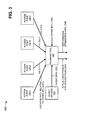
Fig. 3 is a diagram of example interactions between components of anexample portion 300 ofnetwork 100. As illustrated,example network portion 300 may includeaccess points 120,client devices 130, andplanning tool 145. Access points 120,client devices 130, andplanning tool 145 may include the features described above in connection with, for example, one or more ofFigs. 1 and2 . - As further shown in
Fig. 3 , the fouraccess points 120 may be labeled 120-1, 120-2, 120-3, and 120-4 for ease of explanation. It may be assumed that access points 120-1 through 120-4 are located on the same floor of a building. Access point 120-1 may provide (e.g., based on RF information associated with access point 120-1) location information 310-1 toplanning tool 145. Location information 310-1 may include an estimated location of access point 120-1 relative to other access points 120-2, 120-3, and 120-4. Access point 120-2 may provide (e.g., based on RF information associated with access point 120-2) location information 310-2 toplanning tool 145. Location information 310-2 may include an estimated location of access point 120-2 relative to other access points 120-1, 120-3, and 120-4. Access point 120-3 may provide (e.g., based on RF information associated with access point 120-3) location information 310-3 toplanning tool 145. Location information 310-3 may include an estimated location of access point 120-3 relative to other access points 120-1, 120-2, and 120-4. Access point 120-4 may provide (e.g., based on RF information associated with access point 120-4) location information 310-4 toplanning tool 145. Location information 310-4 may include an estimated location of access point 120-4 relative to other access points 120-1, 120-2, and 120-3. Location information 310-1, 310-2, 310-3, 310-4 maybe collectively referred to herein aslocation information 310. -
Client devices 130 may provideclient information 320 toplanning tool 145.Client information 320 may include RF information (e.g., strength of RF signals provided byaccess points 120 to client devices 130) ofclient devices 130 that may be used to determine actual locations of access points 120. For example,client information 320 may include estimated locations ofclient devices 130 relative to accesspoints 120.Client devices 130 may be located on the same floor asaccess points 120 or may be located on different floor(s) than access points 120. - As further shown in
Fig. 3 ,planning tool 145 may receiveother information 330 that may be used to determine actual locations of access points 120.Other information 330 may include location information (e.g., RF information) associated withaccess points 120 provided on different floor(s) than access points 120-1 through 120-4. The RF information of the differentfloor access points 120 may provide estimated locations of the differentfloor access points 120 relative to one or more of access points 120-1 through 120-4. The RF information of the differentfloor access points 120 may also enable the differentfloor access points 120 to be resolved into groups based on an estimated number of floors in the building, base on floor and/or ceiling attenuation values, etc.Other information 330 may also include information provided by wired port virtual LAN (VLAN), traceroute, and other network topology discovery protocols, which may be used to resolve access points 120-1 through 120-4 into a same floor group.Other information 330 may further include information provided by two-dimensional and three-dimensional antenna patterns of access points 120-1 through 120-4, and information provided by embedded accelerometers provided in access points 120-1 through 120-4. -
Planning tool 145 may receivelocation information 310,client information 320, andother information 330, and may determineactual locations 340 of access points 120-1 through 120-4 (e.g., at the floor of the building) based onlocation information 310. In one example implementation,planning tool 145 may utilize a triangulation, method (e.g., similar to a global positioning satellite (GPS) triangulation method) to determineactual locations 340 of access points 120-1 through 120-4 based onlocation information 310. Additionally,planning tool 145 may modify or adjust (if necessary) the determinedactual locations 340 of access points 120-1 through 120-4 based onclient information 320 and/or based on other information 330 (e.g., the location information of the different floor access points 120).Planning tool 145 may map the determinedactual locations 340 of access points 120-1 through 120-4 on a floor plan (e.g., of the floor where access points 120-1 through 120-4 are located), and may provide, for display, the floor plan with the mappedactual locations 340 of access points 120-1 through 120-4. - As further shown in
Fig. 3 ,planning tool 145 may determineperformance optimization information 350 based on one or more oflocation information 310,client information 320, andother information 330.Performance optimization information 350 may include, for example: providing recommendations that a user ofcomputing device 140 rotate, scale, and reposition access points 120-1 through 120-4 inplanning tool 145 relative to the floor plan; usingactual locations 340 of access points 120-1 through 120-4 to recommend adding, moving, and/or removingaccess points 120 to optimize coverage and performance; usingactual locations 340 of access points 120-1 through 120-4 for visualization-based connection, coverage, and throughput monitoring, debugging, and optimization; usingactual locations 340 of access points 120-1 through 120-4 to automatically assign attenuation values to floor plan obstructions (e.g., walls, cubes, ceilings, ducts, doors, etc.); etc.Planning tool 145 may provide, for display,performance optimization information 350 with the floor plan and the mappedactual locations 340 of access points 120-1 through 120-4. - In one example scenario, access points 120-1 through 120-4 may be provided in a building according to a combination of best practices (e.g., install an
access point 120 every twenty (20) feet on the ceiling) and available mounting locations for access points 120-1 through 120-4.Planning tool 145 may receivelocation information 310,client information 320, andother information 330, and may determineactual locations 340 of access points 120-1 through 120-4 based onlocation information 310,client information 320, and/orother information 330. Such an arrangement may enable the exact locations of access points 120 (e.g., on a floor of a building) to be determined, and may enable floor plans with the mapped access point locations to be generated without knowledge of access point IDs (e.g., serial numbers). - Although
Fig. 3 shows example components ofnetwork portion 300, in other implementations,network portion 300 may include fewer components, different components, differently arranged components, or additional components than depicted inFig. 3 . Alternatively, or additionally, one or more components ofnetwork portion 300 may perform one or more other tasks described as being performed by one or more other components ofnetwork portion 300. -
Figs. 4A-4C are diagrams ofexample RF patterns 400 capable of being generated byaccess points 120. Access points 120 may include the features described above in connection with, for example, one or more ofFigs. 1-3 . The fouraccess points 120 depicted inFigs. 4A and4B may be labeled 120-1, 120-2, 120-3, and 120-4 for ease of explanation. It may be assumed that access points 120-1 through 120-4 are located on the same floor of a building. The twoaccess points 120 depicted inFig. 4C may be labeled 120-6 and 120-7 for ease of explanation. It may be assumed that access points 120-6 and 120-7 are located on the same floor of a building. - As shown in
Fig. 4A , each of access points 120-1 through 120-4 may calculate omnidirectional range estimates toother access points 120 based on the strengths of RF signals received from the other access points 120. For example, access point 120-1 may calculate anomnidirectional range estimate 410 to access points 120-2, 120-3, and 120-4 based on the strengths of RF signals received from access points 120-2, 120-3, and 120-4. Access point 120-2 may calculate an omnidirectional range estimate 420 to access points 120-1, 120-3, and 120-4 based on the strengths of RF signals received from access points 120-1, 120-3, and 120-4. Access point 120-3 may calculate anomnidirectional range estimate 430 to access points 120-1, 120-2, and 120-4 based on the strengths of RF signals received from access points 120-1, 120-2, and 120-4. Access point 120-4 may calculate anomnidirectional range estimate 440 to access points 120-1, 120-2, and 120-3 based on the strengths of RF signals received from access points 120-1, 120-2, and 120-3. - Access points 120-1, 120-2, 120-3, and 120-4 may provide omnidirectional range estimates 410, 420, 430, and 440, respectively, to computing device 140 (e.g., to planning tool 145). In one example implementation, omnidirectional range estimates 410, 420, 430, and 440 may correspond to location information 310-1, 310-2, 310-3, and 310-4 (
Fig. 3 ), respectively,Planning tool 145 may utilize a triangulation method (e.g., similar to a GPS triangulation method) to determineactual locations 340 of access points 120-1 through 120-4 based on omnidirectional range estimates 410-440. In the triangulation method, for example, an actual location of access point 120-1 may be calculated from distance measurements (e.g., omnidirectional range estimate 410) to access points 120-2, 120-3 and 120-4. Mathematically, a minimum of four access points 120 (e.g., four omnidirectional range estimates) may be needed to determine the exact position of anaccess point 120, and an actual location of at least one access point 120 (e.g., relative to the building) may need to be known. However, with additional information (e.g.,client information 320 and/or other information 330), less than four access points 120 (e.g., four omnidirectional range estimates) may be needed to determine the exact position of anaccess point 120. In other implementations, the triangular method may be replaced with other methods, such as a trilateration method used in GPS. -
Planning tool 145 may utilize the triangulation method (or the trilateration method) to solve for overlap of omnidirectional range estimates 410-440, which may be used to determine actual locations of access points 120-1 through 120-4. For example, as shown inFig. 4B , the triangulation method may determine an overlap region 450-1 (e.g., which may correspond to the actual location of access point 120-1), an overlap region 450-2 (e.g., which may correspond to the actual location of access point 120-2), an overlap region 450-3 (e.g., which may correspond to the actual location of access point 120-3), and an overlap region 450-4 (e.g., which may correspond to the actual location of access point 120-4).Planning tool 145 may utilize additional information (e.g.,client information 320 and/or other information 330) to modify or adjust the determined actual locations of access points 120-1 through 120-4. - As shown in
Fig. 4C ,access points 120 may generate non-omnidirectional antenna patterns. For example, access point 120-6 may calculate anon-omnidirectional range estimate 460 to access point 120-7 based on the strengths of RF signals received from access points 120-7. Access point 120-7 may calculate anon-omnidirectional range estimate 470 to access point 120-6 based on the strengths of RF signals received from access points 120-6. In such a situation, computing device 140 (e.g., planning tool 145) may utilize non-omnidirectional range estimates 460 and 470 to assist in determining locations of access points 120-6 and 120-7 relative to each other. Computing device 140 (e.g., planning tool 145) may need to rely more heavily on other information (e.g.,client information 320 and/or other information 330) to determine the actual locations of access points 120-6 and 120-7. - Although
Figs. 4A-4C showexample RF patterns 400 capable of being generated byaccess points 120, in other implementations,access points 120 may generate different RF patterns, differently arranged RF patterns, or additional RF patterns than depicted inFigs. 4A-4C . -
Fig. 5 is a diagram of example functional components ofplanning tool 145 ofcomputing device 140. In one implementation, the functions described in connection withFig. 5 may be performed by one or more components of device 200 (Fig. 2 ). As illustrated inFig. 5 ,planning tool 145 may include alocation information determiner 500, aclient information receiver 510, another information receiver 520, atriangulation component 530, afloor plan mapper 540, and anoptimizer 550. -
Location information determiner 500 may include hardware or a combination of hardware and software that may receiveRF information 560 from access points 120.RF information 560 may include signal strength information associated with neighboring access points 120. In one example,location information determiner 500 may convertRF information 560 into distance information betweenaccess points 120, and may calculatelocation information 310 for eachaccess point 120 based on the calculated distance information.Location information determiner 500 may providelocation information 310 totriangulation component 530. -
Client information receiver 510 may include hardware or a combination of hardware and software that may receiveclient information 320 from one ormore client devices 130. As further shown inFig. 5 ,client information receiver 510 may provideclient information 320 totriangulation component 530. -
Other information receiver 520 may include hardware or a combination of hardware and software that may receiveother information 330. For example,other information receiver 520 may receiveother information 330 fromaccess points 120 located on different floors, network topology discovery protocols, from two-dimensional and three-dimensional antenna patterns of access points 120-1 through 120-4, accelerometers provided in access points 120-1 through 120-4, etc. As further shown inFig. 5 ,other information receiver 520 may provideother information 330 totriangulation component 530. -
Triangulation component 530 may include hardware or a combination of hardware and software that may receivelocation information 310 fromlocation information determiner 500,client information 320 fromclient information receiver 510, andother information 330 fromother information receiver 520.Triangulation component 530 may utilize a triangulation method (e.g., similar to a GPS triangulation method) to determineactual locations 570 of access points 120 (e.g., relative to the building) based onlocation information 310. In the triangulation method, for example, an actual location of anaccess point 120 may be calculated from distance measurements (e.g., omnidirectional range estimates) to other access points 120. Mathematically, a minimum of four access points 120 (e.g., four omnidirectional range estimates) may be needed bytriangulation component 530 to determine the exact position of anaccess point 120. However, with additional information (e.g.,client information 320 and/or other information 330), less than four access points 120 (e.g., four omnidirectional range estimates) may be needed bytriangulation component 530 to determine the exact position of anaccess point 120. In other implementations,triangulation component 530 may utilize other methods to determineactual locations 570, such as a trilateration method used in GPS. As further shown inFig. 5 ,triangulation component 530 may provideactual locations 570 tofloor plan mapper 540 and tooptimizer 550. -
Floor plan mapper 540 may include hardware or a combination of hardware and software that may receiveactual locations 570 fromtriangulation component 530, and may receive floor plan information 580 (e.g., frommain memory 230,ROM 240, and/or storage device 250).Floor plan information 580 may include a floor plan of the floor where access points 120 are located.Floor plan mapper 540 may mapactual locations 570 ofaccess points 120 on the floor plan, and may provide, for display, the floor plan with the mapped actual locations ofaccess points 120, as indicated byreference number 340. -
Optimizer 550 may include hardware or a combination of hardware and software that may receiveactual locations 570 fromtriangulation component 530, and may receive floor plan information 580 (e.g., frommain memory 230,ROM 240, and/or storage device 250).Optimizer 550 may determineperformance optimization information 350 basedactual locations 570 andfloor plan information 580.Performance optimization information 350 may include, for example: providing recommendations that a user ofcomputing device 140 rotate, scale, and repositionaccess points 120 relative to the floor plan; usingactual locations 570 to recommend adding, moving, and/or removingaccess points 120 to optimize coverage and performance; usingactual locations 570 for visualization-based connection, coverage, and throughput monitoring, debugging, and optimization; usingactual locations 570 to automatically assign attenuation values to floor plan obstructions (e.g., walls, cubes, ceilings, ducts, doors, etc.); etc.Optimizer 550 may provide, for display,performance optimization information 350 with the floor plan and the mapped actual locations of access points 120. - Although
Fig. 5 shows example functional components ofplanning tool 145, in other implementations,planning tool 145 may include fewer functional components, different functional components, differently arranged functional components, or additional functional components than depicted inFig. 5 . Alternatively, or additionally, one or more functional components ofplanning tool 145 may perform one or more other tasks described as being performed by one or more other functional components ofplanning tool 145. -
Figs. 6 and7 are diagrams ofexample user interfaces tool 145. Each of the user interfaces depicted inFigs. 6 and7 may include a graphical user interface (GUI) or a non-graphical user interface, such as a text-based interface. The user interfaces may provide information to users via a customized interface (e.g., a proprietary interface) and/or other types of interfaces (e.g., a browser-based interface). The user interfaces may receive user inputs via one or more input devices (e.g., input device 260), may be user-configurable (e.g., a user may change the size of the user interfaces, information displayed in the user interfaces, color schemes used by the user interfaces, positions of text, images, icons, windows, etc., in the user interfaces, etc.), and/or may not be user-configurable. The user interfaces may be displayed to a user via one or more output devices (e.g., output device 270). - As illustrated in
Fig. 6 , auser interface 600 may include a floor plan (e.g., of a floor of a building) that includesmultiple rooms 610 defined bymultiple walls 620. In one example, the floor plan may include a floor where access points 120 are located. In another example, the floor plan may correspond to a floor of an office building, androoms 610 may correspond to offices provided on the floor of the office building. - As described above,
planning tool 145 may determine actual locations ofaccess points 120, and may map the determined actual locations ofaccess points 120 on the floor plan. As shown inFig. 6 ,access points 120 may be located at various locations of the floor plan. In one example implementation,user interface 600 may correspond to the floor plan with the mappedactual locations 340 of access points 120-1 through 120-4, as described above in connection withFig. 3 . - As illustrated in
Fig. 7 , auser interface 700 may include a floor plan (e.g., of a floor of a building) that includesmultiple rooms 710 defined bymultiple walls 720. In one example, the floor plan may include a floor where access points 120 are located. In another example, the floor plan may correspond to a floor of an office building, androoms 710 may correspond to offices provided on the floor of the office building. As described above,planning tool 145 may determine actual locations ofaccess points 120, and may map the determined actual locations ofaccess points 120 on the floor plan. As shown inFig. 7 ,access points 120 may be located at various locations of the floor plan. - As further shown in
Fig. 7 ,user interface 700 may provideRF coverage 730 associated withaccess points 120. In one example,RF coverage 730 may not provide complete coverage forrooms 710 of the floor plan. Thus,user interface 700 may indicatecoverage problems 740 associated with access points 120 (e.g., locations whereaccess points 120 fail to provide RF coverage 730). In one example implementation,user interface 700 may providerecommendations 750 fornew access points 120 in order to addresscoverage problems 740. In other example implementations,user interface 700 may provide other performance optimization information 350 (Fig. 3 ), such as providing recommendations to move or removeaccess points 120 to optimize coverage and performance, providing attenuation values to floor plan obstructions (e.g.,walls 720, cubes, ceilings, ducts, doors, etc.), etc. - Although
user interfaces user interfaces Figs. 6 and7 . -
Figs. 8A-9 are flow charts of anexample process 800 for providing automatic access point location, planning, and coverage optimization according to implementations described herein. In one implementation,process 800 may be performed by computing device 140 (e.g., via planning tool 145). In another implementation, some or all ofprocess 800 may be performed by another device in conjunction with computing device 140 (e.g., via planning tool 145). - As illustrated in
Fig. 8A ,process 800 may include determining location information of access points, located on a floor, relative to other access points located on the floor (block 810), and receive information of client devices associated with the access points located on the floor (block 820). For example, in implementations described above in connection withFigs. 3 and5 ,location information determiner 500 ofplanning tool 145 may receiveRF information 560 from access points 120.RF information 560 may include signal strength information associated with neighboring access points 120. In one example,location information determiner 500 may convertRF information 560 into distance information betweenaccess points 120, and may calculatelocation information 310 for eachaccess point 120 based on the calculated distance information.Client devices 130 may provideclient information 320 toplanning tool 145.Client information 320 may include RF information (e.g., strength of RF signals provided byaccess points 120 to client devices 130) ofclient devices 130 that may be used to determine actual locations of access points 120. - As further shown in
Fig. 8A ,process 800 may include receiving location information associated with access points located on a different floor (block 830), and determining, using triangulation, actual locations of the access points located on the floor based on the relative location information of the access points located on the floor (block 840). For example, in implementations described above in connection withFig. 3 ,planning tool 145 may receiveother information 330 that may be used to determine actual locations of access points 120.Other information 330 may include location information (e.g., RF information) associated withaccess points 120 provided on different floor(s) than access points 120-1 through 120-4.Other information 330 may also include information provided by wired port VLAN, traceroute, and other network topology discovery protocols, information provided by two-dimensional and three-dimensional antenna patterns of access points 120-1 through 120-4, and information provided by embedded accelerometers provided in access points 120-1 through 120-4.Planning tool 145 may receivelocation information 310,client information 320, andother information 330, and may determineactual locations 340 of access points 120-1 through 120-4 (e.g., on the floor of the building) based onlocation information 310. In one example implementation,planning tool 145 may utilize a triangulation method to determineactual locations 340 of access points 120-1 through 120-4 based onlocation information 310. - Returning to
Fig. 8A ,process 800 may include adjusting, if necessary, the actual locations of the access points based on the location information of the client devices and/or the location information of access points located on the different floor (block 850). For example, in implementations described above in connection withFig. 3 ,planning tool 145 may modify or adjust (if necessary) the determinedactual locations 340 of access points 120-1 through 120-4 based onclient information 320 and/or based other information 330 (e.g., the location information of the different floor access points 120). - As shown in
Fig. 8B ,process 800 may include mapping the actual locations of the access points, located on the floor, to a floor plan of the floor (block 860), and providing, for display, the floor plan of the floor with the mapped actual locations of the access points (block 870). For example, in implementations described above in connection withFig. 3 ,planning tool 145 may map the determinedactual locations 340 of access points 120-1 through 120-4 on a floor plan (e.g., of the floor where access points 120-1 through 120-4 are located), and may provide, for display, the floor plan with the mappedactual locations 340 of access points 120-1 through 120-4. - As further shown in
Fig. 8B ,process 800 may include providing, for display, performance optimization recommendations for the floor plan with the mapped actual locations of the access points (block 880). For example, in implementations described above in connection withFig. 3 ,planning tool 145 may determineperformance optimization information 350 based on one or more oflocation information 310,client information 320, andother information 330.Planning tool 145 may provide, for display,performance optimization information 350 with the floor plan and the mappedactual locations 340 of access points 120-1 through 120-4. -
Process block 880 may include the process blocks depicted inFig. 9 . As shown inFig. 9 , process block 880 may include providing, for display, coverage problems associated with the actual locations of the access points located on the floor (block 900), providing, for display recommendations to add, move, and/or remove access points located on the floor to optimize coverage and/or performance (block 910), and using the actual locations of the access points located on the floor to assign attenuation values to obstructions provided on the floor (block 920). For example, in implementations described above in connection withFig. 3 ,performance optimization information 350 may include, for example: providing recommendations that a user rotate, scale, and reposition access points 120-1 through 120-4 relative to the floor plan; usingactual locations 340 of access points 120-1 through 120-4 to recommend adding, moving, and/or removingaccess points 120 to optimize coverage and performance; usingactual locations 340 of access points 120-1 through 120-4 for visualization-based connection, coverage, and throughput monitoring, debugging, and optimization; usingactual locations 340 of access points 120-1 through 120-4 to automatically assign attenuation values to floor plan obstructions (e.g., walls, cubes, ceilings, ducts, doors, etc.); etc.Planning tool 145 may provide, for display,performance optimization information 350 with the floor plan and the mappedactual locations 340 of access points 120-1 through 120-4. - Systems and/or methods described herein may utilize RF discovery to automatically determine locations of access points (e.g., in a WLAN) relative to other access points in the WLAN. The systems and/or methods may also utilize RF discovery to resolve access points into groups (e.g., access points residing on the same floor of a building). The systems and/or methods may provide the relative location information to a planning tool, and the planning tool may utilize the relative location information to determine the actual locations of the access points. The planning tool may map the actual locations of the access points to a floor plan (e.g., of a building), and may utilize the floor plan with the mapped actual locations of the access points to provide performance optimization recommendations for the WLAN.
- The foregoing description of implementations provides illustration and description, but is not intended to be exhaustive or to limit the invention to the precise form disclosed. Modifications and variations are possible in light of the above teachings or may be acquired from practice of the invention.
- For example, while series of blocks have been described with regard to
Figs. 8A-9 , the order of the blocks may be modified in other implementations. Further, non-dependent blocks may be performed in parallel. - It will be apparent that example aspects, as described above, may be implemented in many different forms of software, firmware, and hardware in the implementations illustrated in the figures. The actual software code or specialized control hardware used to implement these aspects should not be construed as limiting. Thus, the operation and behavior of the aspects were described without reference to the specific software code--it being understood that software and control hardware could be designed to implement the aspects based on the description herein.
- Even though particular combinations of features are recited in the claims and/or disclosed in the specification, these combinations are not intended to limit the disclosure of the invention. In fact, many of these features may be combined in ways not specifically recited in the claims and/or disclosed in the specification. Although each dependent claim listed below may directly depend on only one other claim, the disclosure of the invention includes each dependent claim in combination with every other claim in the claim set.
- No element, act, or instruction used in the present application should be construed as critical or essential to the invention unless explicitly described as such. Also, as used herein, the article "a" is intended to include one or more items. Where only one item is intended, the term "one" or similar language is used. Further, the phrase "based on" is intended to mean "based, at least in part, on" unless explicitly stated otherwise.
Claims (15)
- A method comprising:receiving, by a computing device, distances between an access point, located on a floor of a building, and other access points located on the floor of the building;determining, by the computing device and based on the distances, relative location information associated with the access point, where the relative location information provides a location of the access point relative to the other access points;determining, by the computing device, an actual location of the access point based on the relative location information;mapping, by the computing device, the actual location of the access point to a floor plan of the floor; andproviding, by the computing device and for display, the floor plan including the mapped actual location of the access point.
- The method of claim 1, further comprising:determining additional relative location information associated with the other access points located on the floor;determining, based on the additional relative location information, actual locations of the other access points;mapping the actual locations of the other access points to the floor plan;
andproviding, for display, the floor plan including the mapped actual locations of the other access points. - The method of claim 2, further comprising:determining, based on the floor plan, the actual location of the access point, and the actual locations of the other access points, performance optimization information;determining, based on the performance optimization information, coverage problems associated with the actual location of the access point and the actual locations of the other access points; andproviding, for display and based on the performance optimization information and the coverage problems, a recommendation to:add one or more additional access points to the floor, orchange the actual location of one or more of the other access points.
- The method of claim 3, where determining the performance optimization information includes:assigning, based on the floor plan, the actual location of the access point, and the actual locations of the other access points, attenuation values to obstructions associated with the floor.
- The method of any one of the preceding claims, further comprising:receiving client information from one or more client devices associated with the access point;receiving location information associated with one or more access points located on a different floor of the building; andadjusting the determined actual location of the access point based on at least one of the client information or the location information associated with the one or more access points located on the different floor.
- A device, comprising:a memory to store a plurality of instructions; anda processor to execute instructions in the memory to:receive distances between an access point, located on a floor of a building, and other access points located on the floor of the building,determine, based on the distances, relative location information associated with the access point, where the relative location information provides a location of the access point relative to the other access points,determine, based on the relative location information, an actual location of the access point,map the actual location of the access point to a floor plan of the floor, andprovide, for display, the floor plan including the mapped actual location of the access point.
- The device of claim 6, where the processor is further to execute instructions in the memory to:determine additional relative location information associated with the other access points located on the floor,determine, based on the additional relative location information, actual locations of the other access points,map the actual locations of the other access points to the floor plan, andprovide, for display, the floor plan including the mapped actual locations of the other access points.
- The device of claim 7, where the processor is further to execute instructions in the memory to:determine, based on the floor plan, the actual location of the access point, and the actual locations of the other access points, performance optimization information;determine, based on the floor plan, the actual location of the access point, and the actual locations of the other access points, coverage problems associated with the actual locations of the access point and the actual locations of the other access points, andprovide, based on the performance optimization information and the coverage problems, a recommendation to:add one or more access points to the floor, oradjust the actual location of one or more of the other access points.
- The device of claim 7 or claim 8, where, when determining the performance optimization information, the processor is further to execute instructions in the memory to:assign, based on the floor plan, the actual location of the access point, and the actual locations of the other access points, attenuation values to obstructions associated with the floor.
- The device of any one of claims 6 to 9, where the processor is further to execute instructions in the memory to:receive client information from one or more client devices associated with the access point,receive location information associated with one or more access points located on a different floor of the building, andadjust the determined actual location of the access point based on at least one of the client information or the location information associated with the one or more access points located on the different floor.
- One or more computer-readable media storing instructions executable by one or more processors, the media storing one or more instructions for:receiving distances between an access point, located on a level of a building, and other access points located on the level of the building;determining, based on the distances, relative location information associated with the access point, where the relative location information provides a location of the access point relative to the other access points;determining, based on the relative location information, an actual location of the access point;mapping the actual location of the access point to a floor plan of the level of the building; andproviding, for display, the floor plan including the mapped actual location of the access point.
- The one or more computer-readable media of claim 11, further storing one or more instructions for:determining additional relative location information associated with the other access points located on the level of the building;determining, based on the additional relative location information, actual locations of the other access points;mapping the actual locations of the other access points to the floor plan;
andproviding, for display, the floor plan including the mapped actual locations of the other access points. - The one or more computer-readable media of claim 12, further storing one or more instructions for:determining, based on the floor plan, the actual location of the access point, and the actual locations of the other access points, performance optimization information;determining, based on the performance optimization information, coverage problems associated with the actual location of the access point and the actual locations of the other access points; andproviding, for display and based on the performance optimization information and the coverage problems, a recommendation to:add one or more additional access points to the level of the building, orchange the actual location of one or more of the other access points.
- The one or more computer-readable media of claim 13, where the one or more instructions for determining the performance optimization information, further comprise one or more instructions for:assigning, based on floor plan, the actual location of the access point, and the actual locations of the other access points, attenuation values to obstructions associated with the level.
- The one or more computer-readable media of any one of claim 11 to 14, further storing one or more instructions for:receiving client information from one or more client devices associated with the access point;receiving location information associated with one or more access points located on a different level of the building; andadjusting the determined actual location of the access point based on at least one of the client information or the location information associated with the one or more access points located on the different level of the building.
Priority Applications (1)
| Application Number | Priority Date | Filing Date | Title |
|---|---|---|---|
| EP17166663.9A EP3223551A1 (en) | 2010-11-22 | 2011-05-20 | Automatic access point location, planning and coverage optimization |
Applications Claiming Priority (1)
| Application Number | Priority Date | Filing Date | Title |
|---|---|---|---|
| US12/951,458 US8744352B2 (en) | 2010-11-22 | 2010-11-22 | Automatic access point location, planning, and coverage optimization |
Related Child Applications (1)
| Application Number | Title | Priority Date | Filing Date |
|---|---|---|---|
| EP17166663.9A Division EP3223551A1 (en) | 2010-11-22 | 2011-05-20 | Automatic access point location, planning and coverage optimization |
Publications (2)
| Publication Number | Publication Date |
|---|---|
| EP2456251A1 true EP2456251A1 (en) | 2012-05-23 |
| EP2456251B1 EP2456251B1 (en) | 2017-05-10 |
Family
ID=45531612
Family Applications (2)
| Application Number | Title | Priority Date | Filing Date |
|---|---|---|---|
| EP11167002.2A Active EP2456251B1 (en) | 2010-11-22 | 2011-05-20 | Automatic access point location, planning, and coverage optimization |
| EP17166663.9A Withdrawn EP3223551A1 (en) | 2010-11-22 | 2011-05-20 | Automatic access point location, planning and coverage optimization |
Family Applications After (1)
| Application Number | Title | Priority Date | Filing Date |
|---|---|---|---|
| EP17166663.9A Withdrawn EP3223551A1 (en) | 2010-11-22 | 2011-05-20 | Automatic access point location, planning and coverage optimization |
Country Status (3)
| Country | Link |
|---|---|
| US (1) | US8744352B2 (en) |
| EP (2) | EP2456251B1 (en) |
| CN (1) | CN102480744B (en) |
Cited By (5)
| Publication number | Priority date | Publication date | Assignee | Title |
|---|---|---|---|---|
| WO2014003770A1 (en) * | 2012-06-29 | 2014-01-03 | Hewlett-Packard Development Company, L.P. | Generation of access point configuration change based on a generated coverage monitor |
| EP2858404A1 (en) * | 2013-09-29 | 2015-04-08 | Sony Corporation | Wireless network monitoring device, method and device in wireless communication system |
| GB2550208A (en) * | 2016-05-13 | 2017-11-15 | Here Global Bv | Determining one or more potential installation positions and/or areas for installing one or more radio positioning support devices |
| CN110072242A (en) * | 2019-04-18 | 2019-07-30 | Oppo广东移动通信有限公司 | Network signal adjusting method, device, routing device, terminal and storage medium |
| US11122443B2 (en) | 2019-09-19 | 2021-09-14 | Cisco Technology, Inc. | Automated access point mapping systems and methods |
Families Citing this family (40)
| Publication number | Priority date | Publication date | Assignee | Title |
|---|---|---|---|---|
| US9369839B2 (en) * | 2011-05-18 | 2016-06-14 | Medappit Llc | Network architecture for synchronized display |
| US9763037B2 (en) * | 2011-05-18 | 2017-09-12 | Medappit Llc | Network architecture for synchronized display |
| US20130172005A1 (en) * | 2012-01-03 | 2013-07-04 | QUALCOMM ATHEROS Incorporated | Calculating wi-fi access point locations using wave of discovery |
| US9544831B2 (en) * | 2012-09-07 | 2017-01-10 | Spot On Networks Llc | System and method for network user isolation |
| US9641307B2 (en) * | 2012-09-07 | 2017-05-02 | Spot On Networks, LLC | System and method for wireless access point layout and network operation |
| US9888360B2 (en) * | 2012-11-01 | 2018-02-06 | Qualcomm Incorporated | Methods to optimize and streamline AP placement on floor plan |
| US9474012B2 (en) * | 2013-02-16 | 2016-10-18 | Qualcomm Incorporated | Focused assistance data for WiFi access points and femtocells |
| US20140244817A1 (en) * | 2013-02-28 | 2014-08-28 | Honeywell International Inc. | Deploying a network of nodes |
| US9369835B2 (en) * | 2013-09-24 | 2016-06-14 | Qualcomm Incorporated | Method and apparatus for enhancing access point databases |
| US9107043B2 (en) * | 2013-09-30 | 2015-08-11 | Qualcomm Incorporated | Determining coordinates of access points in an indoor position location system |
| US9310463B2 (en) * | 2013-11-06 | 2016-04-12 | Cisco Technology, Inc. | Detecting incorrectly placed access points |
| US20150124630A1 (en) * | 2013-11-07 | 2015-05-07 | Arris Enterprises, Inc. | AUTOMATIC LOCATION IDENTIFICATION OF CABLE Wi-Fi AND SMALL CELL NODES IN HFC NETWORKS AND THEIR INTEGRATION INTO INVENTORY DATABASES |
| CN104717664B (en) * | 2013-12-13 | 2019-08-23 | 方正国际软件(北京)有限公司 | The cloth arranging method of required hotspot device in a kind of wifi indoor positioning |
| US20150264581A1 (en) * | 2014-03-11 | 2015-09-17 | Honeywell International Inc | Method of placing wireless devices for rf planning |
| US10939407B2 (en) | 2014-03-28 | 2021-03-02 | Apple Inc. | Method and apparatus for Wi-Fi location determination |
| US9807549B2 (en) * | 2014-07-18 | 2017-10-31 | Intel Corporation | Systems and methods for adaptive multi-feature semantic location sensing |
| US9717067B2 (en) * | 2014-09-09 | 2017-07-25 | Vivint, Inc. | Location-based access point module control |
| US10560462B2 (en) * | 2014-09-26 | 2020-02-11 | Intel Corporation | Context-based resource access mediation |
| KR102280542B1 (en) | 2015-01-13 | 2021-07-22 | 삼성전자 주식회사 | Electronic device, Wireless relay device, and Method for providing location information of the wireless relay device |
| US9654904B2 (en) * | 2015-02-19 | 2017-05-16 | Xerox Corporation | System and method for flexibly pairing devices using adaptive variable thresholding |
| US10244413B2 (en) * | 2015-02-20 | 2019-03-26 | Tempo Communications, Inc. | System and method for generating a graphic illustration of wireless network performance |
| CN105227373A (en) * | 2015-10-22 | 2016-01-06 | 上海斐讯数据通信技术有限公司 | Based on multi-layer topology discovery system for networks and the method for cloud controller |
| CN105722103A (en) * | 2016-02-18 | 2016-06-29 | 青岛海信电器股份有限公司 | Indoor wireless router signal coverage determination method |
| US10595162B2 (en) | 2016-03-18 | 2020-03-17 | Qualcomm Incorporated | Access point environment characterization |
| US10645593B2 (en) | 2016-04-15 | 2020-05-05 | Tempo Communications, Inc. | Systems and methods for determining and optimizing performance of wireless networks having multiple access points |
| CN107306403A (en) * | 2016-04-21 | 2017-10-31 | 富士通株式会社 | For the method for wireless network deployment, device and terminal device |
| US9779545B1 (en) * | 2016-06-30 | 2017-10-03 | Microsoft Technology Licensing, Llc | Footprint based business label placement |
| TWI619403B (en) * | 2016-07-18 | 2018-03-21 | 智易科技股份有限公司 | Mobile management system, method for managing a local area network, and computer-readable storage device |
| US10360335B2 (en) | 2016-08-29 | 2019-07-23 | Tempo Communications, Inc. | Distributed sensor network for measuring and optimizing wireless networks |
| CN108307341B (en) * | 2016-09-13 | 2021-05-04 | 北京易方通达科技有限公司 | Method and device for automatically positioning wireless equipment in building |
| DE102016117530B4 (en) | 2016-09-16 | 2020-06-04 | Deutsche Telekom Ag | WiFi roaming |
| CN108616886B (en) * | 2016-12-14 | 2021-06-08 | 上海掌门科技有限公司 | Method and equipment for generating wireless access point topological network |
| KR20180098077A (en) * | 2017-02-24 | 2018-09-03 | 삼성전자주식회사 | Electronic device and method for determining a sutable location of access point device thereof |
| CN108337637B (en) * | 2017-08-18 | 2020-08-25 | 锐捷网络股份有限公司 | Method and equipment for generating Wireless Local Area Network (WLAN) equipment three-dimensional deployment point location diagram |
| CN108429608A (en) * | 2017-10-25 | 2018-08-21 | 大连网月科技股份有限公司 | A kind of method and device automating distribution wireless channel based on high in the clouds |
| US11395371B2 (en) * | 2018-05-31 | 2022-07-19 | Roku, Inc. | Real-time assessment of multimedia service in a particular environment |
| US10932130B2 (en) | 2018-05-31 | 2021-02-23 | Roku, Inc. | System and method for configuring an extender device |
| EP3757595A1 (en) * | 2019-06-26 | 2020-12-30 | HERE Global B.V. | Evaluating a radio positioning performance of a radio positioning system |
| US11743738B2 (en) | 2020-03-05 | 2023-08-29 | Comcast Cable Communications, Llc | Evaluation of access point placement |
| US11240638B1 (en) | 2020-09-11 | 2022-02-01 | Cisco Technology, Inc. | Dynamic allocation of broadcast stream support |
Citations (6)
| Publication number | Priority date | Publication date | Assignee | Title |
|---|---|---|---|---|
| US20050059405A1 (en) * | 2003-09-17 | 2005-03-17 | Trapeze Networks, Inc. | Simulation driven wireless LAN planning |
| US20070025287A1 (en) * | 2005-07-28 | 2007-02-01 | Goren David P | Method and system for determining existence of a predetermined wireless network coverage condition in a wireless network |
| US20070082677A1 (en) * | 2005-10-11 | 2007-04-12 | Cisco Technology, Inc. | Automated configuration of RF WLANs via selected sensors |
| EP2056532A1 (en) * | 2007-11-05 | 2009-05-06 | Spotigo GmbH | Determining positions in a wireless radio system |
| US20100208711A1 (en) * | 2009-02-13 | 2010-08-19 | Sony Corporation | System and method for efficiently populating an access point database |
| WO2010100325A1 (en) * | 2009-03-04 | 2010-09-10 | Nokia Corporation | Building and maintaining wireless node constellations |
Family Cites Families (6)
| Publication number | Priority date | Publication date | Assignee | Title |
|---|---|---|---|---|
| US7143171B2 (en) * | 2000-11-13 | 2006-11-28 | Telefonaktiebolaget Lm Ericsson (Publ) | Access point discovery and selection |
| US7574492B2 (en) * | 2002-09-12 | 2009-08-11 | Broadcom Corporation | Optimizing network configuration from established usage patterns of access points |
| US7295119B2 (en) * | 2003-01-22 | 2007-11-13 | Wireless Valley Communications, Inc. | System and method for indicating the presence or physical location of persons or devices in a site specific representation of a physical environment |
| US7664511B2 (en) * | 2005-12-12 | 2010-02-16 | Nokia Corporation | Mobile location method for WLAN-type systems |
| US8880111B2 (en) * | 2008-07-25 | 2014-11-04 | Qualcomm Incorporated | System and method for network management |
| CN101726725B (en) | 2008-10-29 | 2011-11-09 | 中国科学院自动化研究所 | Wireless sensor network node positioning method based on global optimization strategy |
-
2010
- 2010-11-22 US US12/951,458 patent/US8744352B2/en active Active
-
2011
- 2011-05-20 CN CN201110132314.3A patent/CN102480744B/en active Active
- 2011-05-20 EP EP11167002.2A patent/EP2456251B1/en active Active
- 2011-05-20 EP EP17166663.9A patent/EP3223551A1/en not_active Withdrawn
Patent Citations (6)
| Publication number | Priority date | Publication date | Assignee | Title |
|---|---|---|---|---|
| US20050059405A1 (en) * | 2003-09-17 | 2005-03-17 | Trapeze Networks, Inc. | Simulation driven wireless LAN planning |
| US20070025287A1 (en) * | 2005-07-28 | 2007-02-01 | Goren David P | Method and system for determining existence of a predetermined wireless network coverage condition in a wireless network |
| US20070082677A1 (en) * | 2005-10-11 | 2007-04-12 | Cisco Technology, Inc. | Automated configuration of RF WLANs via selected sensors |
| EP2056532A1 (en) * | 2007-11-05 | 2009-05-06 | Spotigo GmbH | Determining positions in a wireless radio system |
| US20100208711A1 (en) * | 2009-02-13 | 2010-08-19 | Sony Corporation | System and method for efficiently populating an access point database |
| WO2010100325A1 (en) * | 2009-03-04 | 2010-09-10 | Nokia Corporation | Building and maintaining wireless node constellations |
Cited By (11)
| Publication number | Priority date | Publication date | Assignee | Title |
|---|---|---|---|---|
| WO2014003770A1 (en) * | 2012-06-29 | 2014-01-03 | Hewlett-Packard Development Company, L.P. | Generation of access point configuration change based on a generated coverage monitor |
| EP2868132A4 (en) * | 2012-06-29 | 2016-03-30 | Hewlett Packard Development Co | Generation of access point configuration change based on a generated coverage monitor |
| US10172016B2 (en) | 2012-06-29 | 2019-01-01 | Hewlett Packard Enterprise Development Lp | Generation of access point configuration change based on a generated coverage monitor |
| US10869203B2 (en) | 2012-06-29 | 2020-12-15 | Hewlett Packard Enterprise Development Lp | Generation of access point configuration change based on a generated coverage monitor |
| EP2858404A1 (en) * | 2013-09-29 | 2015-04-08 | Sony Corporation | Wireless network monitoring device, method and device in wireless communication system |
| GB2550208A (en) * | 2016-05-13 | 2017-11-15 | Here Global Bv | Determining one or more potential installation positions and/or areas for installing one or more radio positioning support devices |
| US20170332248A1 (en) * | 2016-05-13 | 2017-11-16 | Here Global B.V. | Determining one or more potential installation positions and/or areas for installing one or more radio positioning support devices |
| EP3252492A1 (en) * | 2016-05-13 | 2017-12-06 | HERE Global B.V. | Determining one or more potential installation positions and/or areas for installing one or more radio positioning support devices |
| US10484880B2 (en) | 2016-05-13 | 2019-11-19 | Here Global B.V. | Determining one or more potential installation positions and/or areas for installing one or more radio positioning support devices |
| CN110072242A (en) * | 2019-04-18 | 2019-07-30 | Oppo广东移动通信有限公司 | Network signal adjusting method, device, routing device, terminal and storage medium |
| US11122443B2 (en) | 2019-09-19 | 2021-09-14 | Cisco Technology, Inc. | Automated access point mapping systems and methods |
Also Published As
| Publication number | Publication date |
|---|---|
| CN102480744B (en) | 2015-10-28 |
| CN102480744A (en) | 2012-05-30 |
| US8744352B2 (en) | 2014-06-03 |
| EP3223551A1 (en) | 2017-09-27 |
| EP2456251B1 (en) | 2017-05-10 |
| US20120129559A1 (en) | 2012-05-24 |
Similar Documents
| Publication | Publication Date | Title |
|---|---|---|
| EP2456251B1 (en) | Automatic access point location, planning, and coverage optimization | |
| EP3756374B1 (en) | Detecting radio coverage problems | |
| CA2638754C (en) | Position detection and location tracking in a wireless network | |
| US8457084B2 (en) | Communication group configuration in a network | |
| US9462417B2 (en) | Information communication terminal and location estimation | |
| EP3210322B1 (en) | Presenting wireless-spectrum usage information | |
| US20190281473A1 (en) | Haptic augmented reality assisted self-service for wireless networks | |
| US20140315582A1 (en) | Positioning Method, Client and Positioning System | |
| EP3624513A1 (en) | Geolocating a user equipment | |
| JP5710438B2 (en) | POSITION DETECTION DEVICE, POSITION MANAGEMENT SYSTEM, POSITION DETECTION METHOD, AND PROGRAM | |
| WO2016093860A1 (en) | Calibration-free location determination using wireless communication | |
| GB2509157A (en) | Forming an image using plural pixel devices and determining the position of a plurality of mobile devices | |
| TW201329486A (en) | Positioning method | |
| US20170059690A1 (en) | Determining the location of a mobile computing device | |
| US20200100159A1 (en) | Wireless mesh network topology map management method based on positioning technique | |
| JPWO2021071987A5 (en) | ||
| US11736166B2 (en) | Systems and methods for mapping remote electrical tilt components and antenna ports of a cellular tower based on return loss associated with antennas of the cellular tower | |
| JP6409282B2 (en) | Wired communication device, wired communication relay device, communication system, and program | |
| US11811725B2 (en) | Systems and methods for location-based assignment of network address information | |
| US20180359721A1 (en) | Site model selection for a wireless access point | |
| WO2015191083A1 (en) | Determining the location of a client device | |
| CN117480791A (en) | Method and apparatus for deferred positioning of wireless devices | |
| TW202249516A (en) | Dynamic search window for angle of arrival estimation |
Legal Events
| Date | Code | Title | Description |
|---|---|---|---|
| PUAI | Public reference made under article 153(3) epc to a published international application that has entered the european phase |
Free format text: ORIGINAL CODE: 0009012 |
|
| AK | Designated contracting states |
Kind code of ref document: A1 Designated state(s): AL AT BE BG CH CY CZ DE DK EE ES FI FR GB GR HR HU IE IS IT LI LT LU LV MC MK MT NL NO PL PT RO RS SE SI SK SM TR |
|
| AX | Request for extension of the european patent |
Extension state: BA ME |
|
| 17P | Request for examination filed |
Effective date: 20121112 |
|
| REG | Reference to a national code |
Ref country code: DE Ref legal event code: R079 Ref document number: 602011037732 Country of ref document: DE Free format text: PREVIOUS MAIN CLASS: H04W0016180000 Ipc: H04W0064000000 |
|
| GRAP | Despatch of communication of intention to grant a patent |
Free format text: ORIGINAL CODE: EPIDOSNIGR1 |
|
| STAA | Information on the status of an ep patent application or granted ep patent |
Free format text: STATUS: GRANT OF PATENT IS INTENDED |
|
| RIC1 | Information provided on ipc code assigned before grant |
Ipc: H04W 24/02 20090101ALI20161102BHEP Ipc: H04W 16/18 20090101ALI20161102BHEP Ipc: H04W 64/00 20090101AFI20161102BHEP |
|
| INTG | Intention to grant announced |
Effective date: 20161121 |
|
| GRAS | Grant fee paid |
Free format text: ORIGINAL CODE: EPIDOSNIGR3 |
|
| GRAA | (expected) grant |
Free format text: ORIGINAL CODE: 0009210 |
|
| STAA | Information on the status of an ep patent application or granted ep patent |
Free format text: STATUS: THE PATENT HAS BEEN GRANTED |
|
| AK | Designated contracting states |
Kind code of ref document: B1 Designated state(s): AL AT BE BG CH CY CZ DE DK EE ES FI FR GB GR HR HU IE IS IT LI LT LU LV MC MK MT NL NO PL PT RO RS SE SI SK SM TR |
|
| REG | Reference to a national code |
Ref country code: GB Ref legal event code: FG4D |
|
| REG | Reference to a national code |
Ref country code: AT Ref legal event code: REF Ref document number: 893523 Country of ref document: AT Kind code of ref document: T Effective date: 20170515 Ref country code: CH Ref legal event code: EP |
|
| RAP2 | Party data changed (patent owner data changed or rights of a patent transferred) |
Owner name: JUNIPER NETWORKS, INC. |
|
| REG | Reference to a national code |
Ref country code: NL Ref legal event code: FP |
|
| REG | Reference to a national code |
Ref country code: FR Ref legal event code: PLFP Year of fee payment: 7 |
|
| REG | Reference to a national code |
Ref country code: IE Ref legal event code: FG4D |
|
| REG | Reference to a national code |
Ref country code: DE Ref legal event code: R096 Ref document number: 602011037732 Country of ref document: DE |
|
| PGFP | Annual fee paid to national office [announced via postgrant information from national office to epo] |
Ref country code: NL Payment date: 20170526 Year of fee payment: 7 |
|
| REG | Reference to a national code |
Ref country code: LT Ref legal event code: MG4D |
|
| REG | Reference to a national code |
Ref country code: AT Ref legal event code: MK05 Ref document number: 893523 Country of ref document: AT Kind code of ref document: T Effective date: 20170510 |
|
| PG25 | Lapsed in a contracting state [announced via postgrant information from national office to epo] |
Ref country code: FI Free format text: LAPSE BECAUSE OF FAILURE TO SUBMIT A TRANSLATION OF THE DESCRIPTION OR TO PAY THE FEE WITHIN THE PRESCRIBED TIME-LIMIT Effective date: 20170510 Ref country code: LT Free format text: LAPSE BECAUSE OF FAILURE TO SUBMIT A TRANSLATION OF THE DESCRIPTION OR TO PAY THE FEE WITHIN THE PRESCRIBED TIME-LIMIT Effective date: 20170510 Ref country code: AT Free format text: LAPSE BECAUSE OF FAILURE TO SUBMIT A TRANSLATION OF THE DESCRIPTION OR TO PAY THE FEE WITHIN THE PRESCRIBED TIME-LIMIT Effective date: 20170510 Ref country code: NO Free format text: LAPSE BECAUSE OF FAILURE TO SUBMIT A TRANSLATION OF THE DESCRIPTION OR TO PAY THE FEE WITHIN THE PRESCRIBED TIME-LIMIT Effective date: 20170810 Ref country code: HR Free format text: LAPSE BECAUSE OF FAILURE TO SUBMIT A TRANSLATION OF THE DESCRIPTION OR TO PAY THE FEE WITHIN THE PRESCRIBED TIME-LIMIT Effective date: 20170510 Ref country code: GR Free format text: LAPSE BECAUSE OF FAILURE TO SUBMIT A TRANSLATION OF THE DESCRIPTION OR TO PAY THE FEE WITHIN THE PRESCRIBED TIME-LIMIT Effective date: 20170811 Ref country code: ES Free format text: LAPSE BECAUSE OF FAILURE TO SUBMIT A TRANSLATION OF THE DESCRIPTION OR TO PAY THE FEE WITHIN THE PRESCRIBED TIME-LIMIT Effective date: 20170510 |
|
| PG25 | Lapsed in a contracting state [announced via postgrant information from national office to epo] |
Ref country code: BG Free format text: LAPSE BECAUSE OF FAILURE TO SUBMIT A TRANSLATION OF THE DESCRIPTION OR TO PAY THE FEE WITHIN THE PRESCRIBED TIME-LIMIT Effective date: 20170810 Ref country code: IS Free format text: LAPSE BECAUSE OF FAILURE TO SUBMIT A TRANSLATION OF THE DESCRIPTION OR TO PAY THE FEE WITHIN THE PRESCRIBED TIME-LIMIT Effective date: 20170910 Ref country code: PL Free format text: LAPSE BECAUSE OF FAILURE TO SUBMIT A TRANSLATION OF THE DESCRIPTION OR TO PAY THE FEE WITHIN THE PRESCRIBED TIME-LIMIT Effective date: 20170510 Ref country code: RS Free format text: LAPSE BECAUSE OF FAILURE TO SUBMIT A TRANSLATION OF THE DESCRIPTION OR TO PAY THE FEE WITHIN THE PRESCRIBED TIME-LIMIT Effective date: 20170510 Ref country code: SE Free format text: LAPSE BECAUSE OF FAILURE TO SUBMIT A TRANSLATION OF THE DESCRIPTION OR TO PAY THE FEE WITHIN THE PRESCRIBED TIME-LIMIT Effective date: 20170510 Ref country code: LV Free format text: LAPSE BECAUSE OF FAILURE TO SUBMIT A TRANSLATION OF THE DESCRIPTION OR TO PAY THE FEE WITHIN THE PRESCRIBED TIME-LIMIT Effective date: 20170510 |
|
| REG | Reference to a national code |
Ref country code: CH Ref legal event code: PL |
|
| PG25 | Lapsed in a contracting state [announced via postgrant information from national office to epo] |
Ref country code: SK Free format text: LAPSE BECAUSE OF FAILURE TO SUBMIT A TRANSLATION OF THE DESCRIPTION OR TO PAY THE FEE WITHIN THE PRESCRIBED TIME-LIMIT Effective date: 20170510 Ref country code: DK Free format text: LAPSE BECAUSE OF FAILURE TO SUBMIT A TRANSLATION OF THE DESCRIPTION OR TO PAY THE FEE WITHIN THE PRESCRIBED TIME-LIMIT Effective date: 20170510 Ref country code: CZ Free format text: LAPSE BECAUSE OF FAILURE TO SUBMIT A TRANSLATION OF THE DESCRIPTION OR TO PAY THE FEE WITHIN THE PRESCRIBED TIME-LIMIT Effective date: 20170510 Ref country code: RO Free format text: LAPSE BECAUSE OF FAILURE TO SUBMIT A TRANSLATION OF THE DESCRIPTION OR TO PAY THE FEE WITHIN THE PRESCRIBED TIME-LIMIT Effective date: 20170510 Ref country code: EE Free format text: LAPSE BECAUSE OF FAILURE TO SUBMIT A TRANSLATION OF THE DESCRIPTION OR TO PAY THE FEE WITHIN THE PRESCRIBED TIME-LIMIT Effective date: 20170510 |
|
| REG | Reference to a national code |
Ref country code: DE Ref legal event code: R097 Ref document number: 602011037732 Country of ref document: DE |
|
| REG | Reference to a national code |
Ref country code: IE Ref legal event code: MM4A |
|
| PG25 | Lapsed in a contracting state [announced via postgrant information from national office to epo] |
Ref country code: CH Free format text: LAPSE BECAUSE OF NON-PAYMENT OF DUE FEES Effective date: 20170531 Ref country code: LI Free format text: LAPSE BECAUSE OF NON-PAYMENT OF DUE FEES Effective date: 20170531 Ref country code: IT Free format text: LAPSE BECAUSE OF FAILURE TO SUBMIT A TRANSLATION OF THE DESCRIPTION OR TO PAY THE FEE WITHIN THE PRESCRIBED TIME-LIMIT Effective date: 20170510 Ref country code: SM Free format text: LAPSE BECAUSE OF FAILURE TO SUBMIT A TRANSLATION OF THE DESCRIPTION OR TO PAY THE FEE WITHIN THE PRESCRIBED TIME-LIMIT Effective date: 20170510 |
|
| PLBE | No opposition filed within time limit |
Free format text: ORIGINAL CODE: 0009261 |
|
| STAA | Information on the status of an ep patent application or granted ep patent |
Free format text: STATUS: NO OPPOSITION FILED WITHIN TIME LIMIT |
|
| PG25 | Lapsed in a contracting state [announced via postgrant information from national office to epo] |
Ref country code: LU Free format text: LAPSE BECAUSE OF NON-PAYMENT OF DUE FEES Effective date: 20170520 |
|
| 26N | No opposition filed |
Effective date: 20180213 |
|
| REG | Reference to a national code |
Ref country code: BE Ref legal event code: MM Effective date: 20170531 |
|
| PG25 | Lapsed in a contracting state [announced via postgrant information from national office to epo] |
Ref country code: IE Free format text: LAPSE BECAUSE OF NON-PAYMENT OF DUE FEES Effective date: 20170520 |
|
| REG | Reference to a national code |
Ref country code: FR Ref legal event code: PLFP Year of fee payment: 8 |
|
| PG25 | Lapsed in a contracting state [announced via postgrant information from national office to epo] |
Ref country code: SI Free format text: LAPSE BECAUSE OF FAILURE TO SUBMIT A TRANSLATION OF THE DESCRIPTION OR TO PAY THE FEE WITHIN THE PRESCRIBED TIME-LIMIT Effective date: 20170510 |
|
| PG25 | Lapsed in a contracting state [announced via postgrant information from national office to epo] |
Ref country code: BE Free format text: LAPSE BECAUSE OF NON-PAYMENT OF DUE FEES Effective date: 20170531 |
|
| PG25 | Lapsed in a contracting state [announced via postgrant information from national office to epo] |
Ref country code: MT Free format text: LAPSE BECAUSE OF NON-PAYMENT OF DUE FEES Effective date: 20170520 |
|
| REG | Reference to a national code |
Ref country code: NL Ref legal event code: MM Effective date: 20180601 |
|
| PG25 | Lapsed in a contracting state [announced via postgrant information from national office to epo] |
Ref country code: NL Free format text: LAPSE BECAUSE OF NON-PAYMENT OF DUE FEES Effective date: 20180601 |
|
| PG25 | Lapsed in a contracting state [announced via postgrant information from national office to epo] |
Ref country code: MC Free format text: LAPSE BECAUSE OF FAILURE TO SUBMIT A TRANSLATION OF THE DESCRIPTION OR TO PAY THE FEE WITHIN THE PRESCRIBED TIME-LIMIT Effective date: 20170510 Ref country code: HU Free format text: LAPSE BECAUSE OF FAILURE TO SUBMIT A TRANSLATION OF THE DESCRIPTION OR TO PAY THE FEE WITHIN THE PRESCRIBED TIME-LIMIT; INVALID AB INITIO Effective date: 20110520 |
|
| PG25 | Lapsed in a contracting state [announced via postgrant information from national office to epo] |
Ref country code: CY Free format text: LAPSE BECAUSE OF NON-PAYMENT OF DUE FEES Effective date: 20170510 |
|
| PG25 | Lapsed in a contracting state [announced via postgrant information from national office to epo] |
Ref country code: MK Free format text: LAPSE BECAUSE OF FAILURE TO SUBMIT A TRANSLATION OF THE DESCRIPTION OR TO PAY THE FEE WITHIN THE PRESCRIBED TIME-LIMIT Effective date: 20170510 |
|
| PG25 | Lapsed in a contracting state [announced via postgrant information from national office to epo] |
Ref country code: TR Free format text: LAPSE BECAUSE OF FAILURE TO SUBMIT A TRANSLATION OF THE DESCRIPTION OR TO PAY THE FEE WITHIN THE PRESCRIBED TIME-LIMIT Effective date: 20170510 |
|
| PG25 | Lapsed in a contracting state [announced via postgrant information from national office to epo] |
Ref country code: PT Free format text: LAPSE BECAUSE OF FAILURE TO SUBMIT A TRANSLATION OF THE DESCRIPTION OR TO PAY THE FEE WITHIN THE PRESCRIBED TIME-LIMIT Effective date: 20170510 |
|
| PG25 | Lapsed in a contracting state [announced via postgrant information from national office to epo] |
Ref country code: AL Free format text: LAPSE BECAUSE OF FAILURE TO SUBMIT A TRANSLATION OF THE DESCRIPTION OR TO PAY THE FEE WITHIN THE PRESCRIBED TIME-LIMIT Effective date: 20170510 |
|
| REG | Reference to a national code |
Ref country code: DE Ref legal event code: R082 Ref document number: 602011037732 Country of ref document: DE Representative=s name: D YOUNG & CO LLP, DE |
|
| P01 | Opt-out of the competence of the unified patent court (upc) registered |
Effective date: 20230520 |
|
| PGFP | Annual fee paid to national office [announced via postgrant information from national office to epo] |
Ref country code: FR Payment date: 20230420 Year of fee payment: 13 Ref country code: DE Payment date: 20230419 Year of fee payment: 13 |
|
| PGFP | Annual fee paid to national office [announced via postgrant information from national office to epo] |
Ref country code: GB Payment date: 20230420 Year of fee payment: 13 |