EP2594209A1 - Patient-specific surgical instrument for preparing a bone of the patient - Google Patents
Patient-specific surgical instrument for preparing a bone of the patient Download PDFInfo
- Publication number
- EP2594209A1 EP2594209A1 EP12192593.7A EP12192593A EP2594209A1 EP 2594209 A1 EP2594209 A1 EP 2594209A1 EP 12192593 A EP12192593 A EP 12192593A EP 2594209 A1 EP2594209 A1 EP 2594209A1
- Authority
- EP
- European Patent Office
- Prior art keywords
- instrumentation
- block
- bone
- patient
- release means
- Prior art date
- Legal status (The legal status is an assumption and is not a legal conclusion. Google has not performed a legal analysis and makes no representation as to the accuracy of the status listed.)
- Granted
Links
- 210000000988 bone and bone Anatomy 0.000 title claims abstract description 66
- 238000002360 preparation method Methods 0.000 claims abstract description 16
- 239000000463 material Substances 0.000 claims description 20
- 239000000843 powder Substances 0.000 claims description 13
- 238000004519 manufacturing process Methods 0.000 claims description 11
- 230000002441 reversible effect Effects 0.000 claims description 8
- 238000000149 argon plasma sintering Methods 0.000 claims 1
- 210000000689 upper leg Anatomy 0.000 description 50
- 210000002816 gill Anatomy 0.000 description 12
- 230000036961 partial effect Effects 0.000 description 12
- 238000005520 cutting process Methods 0.000 description 9
- 238000000926 separation method Methods 0.000 description 7
- 238000005245 sintering Methods 0.000 description 7
- 238000001356 surgical procedure Methods 0.000 description 7
- 238000004873 anchoring Methods 0.000 description 6
- 210000003407 lower extremity of femur Anatomy 0.000 description 6
- 239000000470 constituent Substances 0.000 description 5
- 238000005553 drilling Methods 0.000 description 5
- 230000002427 irreversible effect Effects 0.000 description 4
- 230000003313 weakening effect Effects 0.000 description 4
- YMHOBZXQZVXHBM-UHFFFAOYSA-N 2,5-dimethoxy-4-bromophenethylamine Chemical compound COC1=CC(CCN)=C(OC)C=C1Br YMHOBZXQZVXHBM-UHFFFAOYSA-N 0.000 description 3
- 241000545067 Venus Species 0.000 description 3
- 210000000845 cartilage Anatomy 0.000 description 3
- 238000013461 design Methods 0.000 description 3
- 239000013013 elastic material Substances 0.000 description 3
- 238000002513 implantation Methods 0.000 description 3
- 238000013507 mapping Methods 0.000 description 3
- 239000002184 metal Substances 0.000 description 3
- 238000007664 blowing Methods 0.000 description 2
- 230000000295 complement effect Effects 0.000 description 2
- 238000003780 insertion Methods 0.000 description 2
- 230000037431 insertion Effects 0.000 description 2
- 230000000670 limiting effect Effects 0.000 description 2
- 238000005192 partition Methods 0.000 description 2
- 230000002829 reductive effect Effects 0.000 description 2
- 241001465754 Metazoa Species 0.000 description 1
- 238000013459 approach Methods 0.000 description 1
- 230000015572 biosynthetic process Effects 0.000 description 1
- 230000000903 blocking effect Effects 0.000 description 1
- 210000004027 cell Anatomy 0.000 description 1
- 238000006073 displacement reaction Methods 0.000 description 1
- 210000003811 finger Anatomy 0.000 description 1
- 230000001788 irregular Effects 0.000 description 1
- 210000003127 knee Anatomy 0.000 description 1
- 210000002414 leg Anatomy 0.000 description 1
- 238000012423 maintenance Methods 0.000 description 1
- 230000014759 maintenance of location Effects 0.000 description 1
- 238000000034 method Methods 0.000 description 1
- 230000001902 propagating effect Effects 0.000 description 1
- 238000011084 recovery Methods 0.000 description 1
- 238000002271 resection Methods 0.000 description 1
- 238000000110 selective laser sintering Methods 0.000 description 1
- 125000006850 spacer group Chemical group 0.000 description 1
- 238000010408 sweeping Methods 0.000 description 1
- 210000003813 thumb Anatomy 0.000 description 1
- 238000013519 translation Methods 0.000 description 1
- 238000002604 ultrasonography Methods 0.000 description 1
Images


Classifications
-
- A—HUMAN NECESSITIES
- A61—MEDICAL OR VETERINARY SCIENCE; HYGIENE
- A61B—DIAGNOSIS; SURGERY; IDENTIFICATION
- A61B17/00—Surgical instruments, devices or methods, e.g. tourniquets
- A61B17/14—Surgical saws ; Accessories therefor
- A61B17/15—Guides therefor
- A61B17/154—Guides therefor for preparing bone for knee prosthesis
- A61B17/155—Cutting femur
-
- A—HUMAN NECESSITIES
- A61—MEDICAL OR VETERINARY SCIENCE; HYGIENE
- A61B—DIAGNOSIS; SURGERY; IDENTIFICATION
- A61B17/00—Surgical instruments, devices or methods, e.g. tourniquets
- A61B17/56—Surgical instruments or methods for treatment of bones or joints; Devices specially adapted therefor
- A61B2017/568—Surgical instruments or methods for treatment of bones or joints; Devices specially adapted therefor produced with shape and dimensions specific for an individual patient
-
- B—PERFORMING OPERATIONS; TRANSPORTING
- B33—ADDITIVE MANUFACTURING TECHNOLOGY
- B33Y—ADDITIVE MANUFACTURING, i.e. MANUFACTURING OF THREE-DIMENSIONAL [3-D] OBJECTS BY ADDITIVE DEPOSITION, ADDITIVE AGGLOMERATION OR ADDITIVE LAYERING, e.g. BY 3-D PRINTING, STEREOLITHOGRAPHY OR SELECTIVE LASER SINTERING
- B33Y80/00—Products made by additive manufacturing
Definitions
- the present invention relates to a patient-specific surgical instrumentation for the preparation of a bone of this patient, for example a femur, for implanting a prosthesis component therein.
- the field of the invention is that of so-called "custom-made” or “customized” instrumentations, in connection with a specific patient, on which the instrumentation is intended to be exclusively used by a surgeon.
- This kind of instrumentation specific to a patient is opposed to standard instruments, which are used interchangeably on different patients, if necessary by being reused several times in succession, being cleaned and sterilized between each use.
- the surgeon positions a guide block on the bone, having a surface shaped specifically adapted to the bone of the patient.
- the guide block guides the application on the bone of a bone preparation tool, such as a drill bit or an anchor pin. Thereafter, the guide block must be removed or removed from the bone to allow the positioning of a cutting block. Because the shape of the bone-like guide block is relatively complex, it makes it difficult, if not impossible, to remove bone when the pins are inserted therein.
- US-2007/288030 describes a femoral instrumentation specific to a patient, comprising a femoral block delimiting a fixed bearing surface specifically fitted to the femur.
- the block has a plurality of through holes for receiving pins used for positioning cutting guides.
- Two orifices in the block are open in a direction transverse to the direction of insertion of the pins.
- the openings open on the block allow the surgeon to remove this block without having to remove pins inserted therein.
- the particular shape of these open holes nevertheless implies that the guide of a hole drilling tool, and / or the insertion of a pin, into the bone, may be inaccurate.
- the positioning of the pins is necessarily limited to certain configurations to allow the removal of the block.
- US-2009/087276 discloses a patient-specific surgical instrumentation corresponding to the preamble of claim 1.
- the instrumentation comprises fixing pins inserted into openings through a main part and a secondary part of the block. If such an assembly is too rigid, it is difficult to handle by the surgeon. Conversely, such an assembly may include play, which reduces the accuracy of positioning parts of the block. In this case the cuts are less precise and the prosthesis may be incorrectly positioned, which may lead to an early revision.
- the main part, the abutment and the pins are four separate parts, there is a risk of loss of parts during handling and the instrumentation is impractical to implement.
- the object of the invention is to provide an improved specific surgical instrumentation, providing time and precision to the surgeon.
- the instrumentation is characterized in that the mechanical release means comprise at least one patient-specific cavity, which extends through the block, between the main part and the secondary part, according to a geometrical envelope of the fixed support surface.
- the invention facilitates the surgical manipulations of the surgeon.
- the instrumentation is simple and practical: the specific block is adapted, on the one hand, to position on the bone secondary pins that will subsequently be used to place on the bone a cutting block or any other bone preparation system and, secondly, to be fully or partially clear of the bone without altering the positioning accuracy of these pins.
- the surgeon simply has to break, cut, bend, unclip or remove the mechanical release means of the abutment relative to the main part, depending on the embodiment of these means.
- it is indeed particularly advantageous to guide the application of a drill bit or the like by the abutment before setting up the secondary spindles.
- the release of the abutment is made in a direction that does not induce jamming interference between the portion of the bearing surface delimited by this abutment, and the reliefs of the femur to which this part is adjusted. of the bearing surface.
- the invention makes it possible to form areas of reduced mechanical strength, which are more easily deformable and / or breakable, while ensuring that the block has sufficient mechanical strength when it is positioned on the bone and when the pins are inserted. .
- a cavity that is not specific to the patient ie a generic cavity
- such a compromise would be difficult to obtain because of the complex geometry of the bone.
- an instrumentation comprising a generic cavity would not be satisfactory.
- the instrumentation according to the invention facilitates the surgeon's intraoperative manipulations.
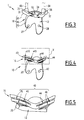
- FIG. 1 to 5 On the Figures 1 to 5 is represented a patient-specific surgical instrumentation 1 for the preparation of a bone B of this patient for the implantation of a prosthesis.
- the bone is the patient's right femur, to be prepared for implantation of a knee prosthesis femoral component. It is understood that the specific surgical instrumentation 1 according to the invention can be adapted to different bones of the human or animal body.
- mapping data relating to the femur B of the patient to be operated are collected.
- these pre-operative mapping data can be obtained in various ways. For example, CT and / or X-ray images and / or ultrasound and / or MRI of the femur B are used.
- sufficient information is available to design and manufacture a patient-specific femoral block.
- the block 10 is shown, on the one hand, in position on the femur B at the figure 1 and, on the other hand, only figures 2 at 5.
- the specific femoral block 10 has a surface 12 provided to be turned towards the femur B, and a surface 14 intended to be turned towards the surgeon when the block 10 is fitted on the femur B.
- the surface 12 is shaped so specifically fitted to the lower end of the femur B and, in use, is fixedly supported against this end of the femur B, marrying the surface of the latter by complementarity of shapes. It is understood that, to achieve such a rigorous fit between the bearing surface 12 and the lower end of the femur B, the surface 12 is drawn using the pre-operative map data relating to the femur.
- the bearing surface 12 has reliefs customized specifically to the operated patient who, by cooperating with complementary reliefs delimited by the surface of the lower end of the femur, allow only one adjusted support configuration on the femur B, as shown on the figure 1 .
- the bearing surface 12 covers anterior and distal regions of the lower end of the femur B, fittingly marry the reliefs of these areas.
- the specific femoral block 10 is intended to be fixedly supported, by its surface 12, on the lower end of the femur B.
- this fixation is achieved thanks to, on the one hand, two through holes 27 and 28 formed through two guide pads, respectively 25 and 26, these holes 27 and 28 connecting the surface 12 with the opposite surface 14 of the block 10 and, secondly, two bone anchoring pins 61 and 62 able to be respectively engaged in complementary manner in the through holes 27 and 28, as shown in FIG. figure 1 , until planting and thus immobilize in the bone material of the femur B.
- the specific femoral block 10 consists of two parts having different respective finalities, as progressively explained hereinafter, namely a main part 20, as well as a secondary part 30 which is detachable from the part 20.
- a junction zone 16 connects parts 20 and 30 of the specific femoral block 10, which is in an initially monolithic form.
- Block 10 can be manufactured by any known means, suitable for the present application.
- the block 10 can be manufactured by selective laser sintering ("laser selective sintering").
- laser selective sintering In this case, the solidified block is surrounded by residual powder after manufacture, then the powder is removed first by sweeping and then by blowing; the block 10 can then be removed from the manufacturing tank, cleaned and sterilized before being used on a patient.
- the main part 20 comprises two branches 21 and 22 which extend from a central portion 23.
- the pads 25 and 26 are formed on the surface 14 of the block 10, respectively on the branches 21 and 22.
- the branch 21 is traversed by the hole 27, while the branch 22 is traversed by the hole 28.
- the central portion 23 is provided, projecting from the surface 14, a stud 29 for fixing a cutting block or any other femur preparation system B, not shown, during a subsequent peroperative step.
- the central portion 23 alone delimits most of the material of the block 10 and the bearing surface 12.
- the secondary portion 30 comprises two branches 31 and 32 which extend from the central portion 23 at the junction zone 16, in the extension of the branches 21 and 22 respectively, following the surface of the femur B.
- the elements 21, 22, 23, 31 and 32 together define the bearing surface 12. Studs 35 and 36 are formed on the surface 14 of the block 10, respectively on the branches 31 and 32.
- the secondary portion 30 is provided with two holes 37 and 38 formed in the guide pads, respectively 35 and 36, which are each adapted to receive a bone preparation tool, such as a drill bit or a bone anchor pin: on the figure 3 such bone preparation tools, respectively referenced 63 and 64, are shown in dashed lines.
- a bone preparation tool such as a drill bit or a bone anchor pin
- the branches 31 and 32 are separated by an intermediate space 33, intended to be placed in service in the extension of the intercondylar space, as shown in FIG. figure 1 .
- a plate 34 extends through the space 33 by connecting the branches 31 and 32, in particular for the purpose of stiffening the secondary portion 30.
- This plate 34 does not define the bearing surface 12 and is therefore, in use , distant from the surface of the femur B. Thus, the plate 34 does not enter the intercondylar space and does not hide it completely.
- the plate 34 may include inscriptions useful to the surgeon, or the block 10 does not include a plate 34.
- the main part 20 is present throughout the use of the instrumentation 1, in the sense that this main part 20 is both the first implementation, being fixed to the femur B by the pins 61 and 62 that we can to qualify as primary pins, and the last released vis-à-vis the femur, while the abutment 30 is, on the contrary, designed for, during the use of the instrumentation, can be separated from the main part 20 by the surgeon.
- the specific femoral block 10 is made available to the surgeon in an initially monolithic form, it is understood that the separation of the abutment 30 from the main part 20 requires the surgeon to break the material between the parts 20 and 30, at the junction zone 16.
- the temporary presence, during the intervention, of the secondary portion 30 vis-à-vis the rest of the block 10 can be understood the interest of the present invention.
- the holes 37 and 38 have been positioned within the block 10 so as to precisely orient the aforementioned secondary pins: during the surgery, when the aforementioned subsequent step, these secondary pins are used to, in turn, guide the positioning of cutting means of the femur B, such as a cutting block, to resect the end of the femur B in one or more planes resection designed to subsequently form corresponding planar supports for fixing a femoral prosthetic component.
- the disengagement of the abutment 30 makes it possible to free up space opposite the area of the femur B on which the holes 37 and 38, until now, had opened, namely the distal zone of the lower end of the femur B.
- the instrumentation 1 comprises means 40 for mechanically disengaging the secondary part 30 with respect to the main part 20 and the femur B, these means 40 being arranged in the junction zone 16 between the main part 20 and the main part 20. secondary part 30.
- the mechanical release means 40 are made of material both with the main part 20 and the secondary part 30, in particular during the manufacture of the block 10 by laser powder sintering.
- the means 40 are distributed between a first region 41 located between the branch 31 and the portion 23 and a second region 42 located between the branch 32 and the portion 23.
- the means 40 comprise a cavity, respectively 43 and 44.
- Each cavity 43 and 44 passes through the block 10 in the junction zone 16 and opens on either side of the branches 31 and 32, at the space 33 and the opposite of this space 33, that is to say generally in the latero-medial direction in use.
- each cavity 43 and 44 is said to be enveloping, insofar as it extends through the block 10 by marrying the external shape of the femur B, in other words by following the geometry of the surface 12, and can therefore be described as a specific cavity to the patient, corresponding to his particular morphology.
- the block 10 has a thickness e10, measured between the surface 12 and the surface 14 in a direction normal to the surface 12, which is substantially constant in the junction zone 16 where the means 40 are located.
- each cavity 43 and 44 has a thickness, respectively e43 and e44, which is constant in the direction normal to the surface 12.
- the means 40 also comprise gills 45 and 46, formed through the block 10, respectively in the region 41 and the region 42.
- the gills 45 open into the cavity 43, with two openings 45 which open at the surface 12 and two gills 45 which open at the surface 14.
- the gills 46 open into the cavity 44, with two gills 46 which open at the surface 12 and two gills 46 which open at the surface 14.
- the gills 45 and 46 have a profile adapted to facilitate the deformation of the material in each of the regions 41 and 42.
- the gills 45 and 46 have an irregular quadrilateral shape, in particular with a planar face and a face of substantially hyperbolic curved shape placed facing each other, which extend in the direction normal to the surface 12.
- the cavities 43 and 44 open out of the block 10, on the sides of the branches 31 and 32 and at the gills 45 and 46, which allows the evacuation of powder. Otherwise, the powder trapped in the cavities may spill onto the patient's bone.
- the cavities 43 and 44 comprise at least one opening opening out of the block 10.
- the mechanical clearance of the abutment 30 with respect to the main part 20 and the femur B, on which this main part 20 is fixed by the primary pins 61 and 62, is produced by breaking the material of the block 10 at 40.
- the regions 41 and 42 can be folded and torn off when the portion 30 is separated from the femur B, with the orifices 37 and 38.
- the cavities 43 and 44 and the gills 45 and 46 constitute primers. fracture facilitating the separation of the parts 20 and 30.
- the means 40 constitute localized weakening elements of the material of the block 10 in the zone 16.
- the mechanical clearance can be done manually or, preferably, using a tool, particularly of the osteotome type, screwdriver or retractor.
- this release tool can be shaped to be able to be housed at the same time in the gills 45 and 46, so that an action of the surgeon on the tool can tear or deform the material regions 41 and 42 simultaneously.
- this block 10 is adapted to be disengaged from the femur B, at the level of the secondary portion 30, with the pins 61 and 62 which are in place in the block 10 and the femur B. It is understood that, according to the detail of the surgical procedure followed intraoperatively, this clearance of the abutment 30 can be achieved either while the holes 37 and 38 are free, after they have guided a drill bit or the like , while secondary pins were passed through these holes and remain in place in the femur until the subsequent operative step inclusive, as explained above. In the second case, it will be noted that the clearance of the secondary portion 30 is accompanied by the sliding of this portion 30 along the aforementioned secondary pins.
- the release of the abutment 30 can be effected in other directions, away from the femur B, however, it is noted that in all cases the separation of the abutment 30 screws of the main part 20 needs to be able to move the part 30 in a non-blocking direction between this part 30 and the femur, whereas, in view of the adjusted wrapping of the femur by the surface 12 of the block 10, the part 30 is stuck in many directions vis-à-vis the specific reliefs of the femur, married by this part 30.
- the part 30 has been released and the femur carries the aforementioned secondary pins, being recalled that the latter are either those which have been passed through the holes 37 and 38, as preparation tools 63 and 64, and which were left in place in the femur, pins that after the 30th have been released, are reported and anchored in the blind holes made just before in the femur by a drill bit or the like, which acted on the femur through the holes 37 and 38, as bone preparation tool 63 and 64 .
- the surgeon uses a cutting block or, more generally, any system for preparing the femur, by positioning this block or this system using the aforementioned secondary pins.
- the block 10 may be shaped differently, in particular to adapt to a different bone femur B of the figure 1 .
- the secondary portion 30 may not have two branches 31 and 32, or have an intermediate portion arranged between the portion 23 and the branches 31 and 32.
- the release means 40 may be distributed in a single a release region located between this intermediate portion and the portion 23. Such a release region is then shaped in a manner comparable to one of the regions 41 or 42 described above, with a single enveloping cavity and gills whose respective profiles are adapted to this particular arrangement.
- the instrumentation 1 comprises a specific block 10 provided with mechanical release means of the secondary portion 30 relative to the main portion 20.
- the block 10 and its parts 20 and 30 are shown partially and schematically to the Figures 6 to 28 at the junction area 16.
- the parts 20 and 30 are represented by parallelepiped elements aligned with each other, with only one region of clearance between them.
- the surface 14 is referenced only to illustrate the orientation of the block 10 and mechanical release means relative to the bone B, not shown, while the bearing surface is not referenced. With reference to this schematic representation, it is nevertheless understood that the block 10 is shaped to conform to the surface of the bone B, as in the example of the Figures 1 to 5 .
- the means 140 comprise bars 142, more precisely three bars 142 on the example of the figure 6 , which extend through the intermediate space 141 and mechanically connect the portions 20 and 30.
- These bars 142 are easily destructible by breaking or tearing, when sufficient tension is exerted by the surgeon on the abutment 30, according to a direction of removal from the main part 20. If the material of the bars 142 is rather fragile, they break suddenly, whereas if the material of the bars 142 is rather ductile, they will deform by constriction, in particular until separation of the parts 20 and 30.
- the mechanical clearance of the portion 30 relative to the portion 20 and the bone B is achieved, irreversibly, by breaking bars 142.
- the means 140 may comprise a different number of bars 142, or they may be shaped differently, without departing from the scope of the invention.
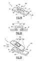
- the means 240 comprise a substantially planar wafer 242 which mechanically connects the parts 20 and 30.
- the wafer 242 is thinner than the parts 20 and 30, with a first concave cup 243 formed on the wafer 242 on the surface side 14 and a wafer 242.
- second concave cup 244 formed on the wafer 242 on the side opposite to the surface 14.
- the bowl 244 forms a recess of material more pronounced than the bowl 243.
- the means 240 also comprise manipulation handles 247 and 248 formed on the surface 14, respectively on the main part 20 and on the secondary part 30.
- the handle 247 is shaped to receive the surgeon's index
- the handle 248 is shaped to receive the surgeon's thumb.
- the mechanical clearance of the portion 30 with respect to the portion 20 and to the bone B is achieved, reversibly, simply by folding the wafer 242.
- the surgeon has the possibility of repositioning this abutment 30 on the bone B to perform a recovery of the holes, if necessary.
- the plate 242 and the bowls 243 and 244, as well as the handles 247 and 248, may be shaped differently without departing from the scope of the invention.
- An intermediate space 341 is formed between the parts 20 and 30, thus forming a discontinuity of the surface 14.
- the means 340 comprise arches 342, more precisely three arches 342 on the example of the figure 8 , which extend over the intermediate space 341, being bent away from the surface 14, and mechanically connect the portions 20 and 30.
- Each arch 342 has a portion 343 thinned relative to the rest of the arch 342. The thinned portions 343 are located midway between the parts 20 and 30 and are aligned along the same axis.
- the irreversible mechanical clearance of the portion 30 relative to the portion 20 and to the bone B is therefore preferably achieved by section of the arches 342 at the portions 343.
- the means 340 may comprise a different number of portions. arches 342, or these may be shaped differently, without departing from the scope of the invention.
- the means 440 comprise a space 441 and bars 442, respectively analogous to the space 141 and the bars 142 of the means 140 described above.
- the means 440 also comprise a first hemispherical dome 443 formed on the portion 20 and a second hemispherical dome 444 formed on the portion 20.
- the dome 443 has a diameter greater than the diameter of the dome 444, so that the dome 444 is partly housed inside the dome 443, without contact between them. Together, the two domes 443 and 444 surround the space 441 and the bars 442.
- a plurality of through-holes 445 are formed in each of the domes 443 and 444. These domes are provided to recover any debris in the chamber. case of a brittle breaking bars 442.
- the orifices 445, as well as the distance between the domes 443 and 444, are sized to prevent the escape of such debris, while allowing the blowing of powder contained in the domes 443 and 444 after manufacture of the block 10 and means 40 by sintering.
- the bars 442 break the domes 443 and 444 are in pivot connection and then the dome 444 can be cleared out of the dome 443, taking care to evacuate any debris.
- the parts 20 and 30 are provided, at the junction zone 16, additional material portions to separate the means 440 relative to the bearing surface of the block 10 and In fact, the presence of the domes 443 and 444 prevents the positioning of the means 440 near the bone B.
- the means 540 comprise a foldable plate 542 comparable to the plate 242 described above, as well as a destructible plate 544.
- the means 540 also comprise a diamond-shaped cavity 545 opening out opposite the face 14 and closed at The diamond-shaped cavity 545 has two vertices directed respectively towards the portions 20 and 30, as well as two vertices each comprising an area 548 of localized weakening of the material between a portion 546 integral with the portion 20 and a portion 544. portion 547 integral with the portion 30.
- the zones 548 yield and their rupture, propagating in the direction of the surface 14 causes a tear of the wafer 544 and a separation of the portions 546 and 547.
- the mechanical clearance of the portion 30 relative to the portion 20 and to bone B is achieved by combining folding and fracture.
- This clearance is reversible thanks to the presence of the wafer 542.
- the means 540 combining folding and breaking can be shaped differently without departing from the scope of the invention.
- the means 640 comprise a tongue 642 and a portion 644 separated by an intermediate space 641.
- the tongue 642 is located on the opposite side to the surface 14 and connected to the portion 20, but not to the portion 30.
- the portion 644 is located from side of the surface 14 and connected to both the portion 20 and the portion 30.
- the thickness of the portion 644, measured in a direction normal to the surface 14 is greater than the thickness of the tongue 642.
- the portion 644 includes a cavity 645 for receiving a tool, not shown, for mechanical clearance of the portion 30. This cavity 645 opens into the space 641 and at the surface 14.
- the portion 644 comprises filamentary elements 646 connecting the side connected to the portion 20 to the side connected to the portion 30.
- the tongue 642 comprises, opposite the cavity 645 in the direction normal to the surface 14, a housing 643 d support of the tool introduced through the cavity 645.
- this tool is of the spacer type, initially having a shape adapted to penetrate into the cavity 645.
- the tool in a first step, is introduced into the cavity 645 and then abuts against the tongue 642, in the housing 643.
- the tool is deployed in the cavity 645, so as to exert opposite forces on the elements 646, until their tearing resulting in the irreversible separation of the parts 20 and 30.
- the means 640 in particular the elements 646, can be shaped differently without departing from the scope of the invention, forming a material bond between the parts 20 and 30, while being easily destructible under the action of the tool introduced into the cavity 645.
- the presence of the tongue 642 prevents that the tool comes scrape against bone B.
- the housing 643 is optional, but facilitates the positioning of the tool within the means 640.
- the means 740 comprise a member 742 which projects from the surface 14 over the space 741.
- the member 742 comprises a tab 744 attached to the part 20 by a thinned portion 746, which thus forms a zone of localized weakening of the material.
- the member 742 is traversed by an orifice 745 centered on an axis A740 and provided for receiving a tool, for example of the screwdriver type.
- a guide member 747 is provided on the surface 14 of the portion 30, in the extension of the axis A740, to receive the tip of the tool.
- the tool is introduced into the orifice 745 along the axis A740 at first, then is raised by bearing in the element 747 and exerting forces opposed to the surface 14 inside the element. 745 orifice in a second time, until the irreversible mechanical release of the portion 30 occur by breaking the portion 746 in a third time.
- the member 742, the orifice 745 and the portion 746 may be shaped differently without departing from the scope of the invention.
- the thinned portion 746 may connect the member 742 to the portion 30, or the member 746 may comprise two thinned portions connecting it to each of the portions 20 and 30.
- the orifice 745 may present a different form of the example of the figure 16 , for example a square shape for breaking the portion 746 by rotation of the tool in the orifice 745.
- the means 840 comprise a plate 842 which connects a first element 843 secured to the part 20 with a second element 844 secured to the part 30.
- the elements 843 and 844 are formed in protrusion beyond the surface 14, while the plate 842 extends over the space 841.
- the plate 842 has a thinned portion 846, thus forming a zone localized weakening of the material.
- Two holes 845 are formed between the elements 843 and 844, facing the portion 846.
- the holes 845 are provided for the introduction and positioning of a tool, able to come against the portion 846 until it breaks.
- the means 840 may be shaped differently without departing from the scope of the invention, for example with a number of holes 845 which depends on the width of the block 10 at the junction zone 16.
- the mechanical release means 40 to 840 are preferably integral with the parts 20 and 30 of the block 10.
- the means 940 comprise a bridge or U-shaped member 942, with two tabs 943 and 944 connected by a central portion 945.
- the orifices 947 and 948 are respectively formed. in parts 20 and 30, opening at the surface 14.
- the member 942 is secured to the parts 20 and 30 during a pre-operative phase, with the tab 943 which is clipped into the orifice 947, the tab 944 which is clipped into the orifice 948, while the portion 945 extends over the space 941.
- the member 942 is removable from the specific block 10 by unclipping the tabs 943 and 944.
- the connection between the member 942 and the parts 20 and 30 is temporary, and the mechanical clearance of the portion 30 is reversible.
- this portion 30 can be easily repositioned on the bone if necessary.
- the means 1040 comprise a member 1042 provided with a rod 1043 secured to the part 30 and a bearing 1044 positioned at the end of the rod 1043 opposite the part 30.
- the rod 1043 is screwed or clipped into an orifice 1057 formed in the portion 30, at the surface 14.
- the rod 1043 is integral with the portion 30.
- the means 1040 also comprise a member 1045 of generally parallelepiped shape, provided with a central portion 1046 pivotally connected in the bearing 1044, a first bearing end 1047 and a second end, opposite the end 1047 relative to the central portion 1046, having a rod 1048 which extends towards the surface 14 of the portion 20.
- An orifice 1058 is formed in the portion 20, at the surface 14.
- the means 1040 are secured to the parts 20 and 30 during a pha pre-operative, with the rod 1048 which is clipped into the hole 1058 and the member 1045 extending over the space 1041.
- a simple support of the surgeon on the end 1047 allows, by leverage, to rotate the member 1045 in the bearing 1044 and unclip the rod 1048 of the orifice 1058.
- the connection between the means 1040 and the parts 20 and 30 is temporary, and the reversible mechanical release of the portion 30 can be performed by simple unclipping.
- this portion 30 can be easily repositioned on the bone if necessary.
- the means 940 and 1040 may be partly made of elastic material.
- the elements 942, 1043 and 1048 may be made of elastic material.
- Such an elastic material contributes to the tensioning of the main part and the secondary part and, on the other hand, guarantees the mechanical strength of the assembly during the positioning of the block, as well as during drilling. .
- the means 1140 comprise a first connecting member 1143 and a second connecting member 1144 adapted to form a mechanical link 1142 of the bridge type between the parts 20 and 30, on top space 1141.
- the member 1143 comprises a stud 1125 provided with a through hole 1127, two branches 1171 connecting the stud 1125 to a tab 1172, a portion 1173 positioned at one end of the tab 1172 opposite the branches 1171 and an orifice 1174 formed on the portion 1173.
- the member 1144 comprises a stud 1135 provided with a through hole 1137, two branches 1181 connecting the stud 1135 to a tab 1182, a portion 1183 positioned at a end of the tab 1182 opposite the branches 1181 and a pin 1184 formed on the portion 1183 parallel to the tab 1182.
- the orifices 1145 and 1147 are formed in the portion 20, while orifices 1146 and 1148 are formed in the part 30, opening at the surface 14.
- the pads 1125 and 1135 and the holes 1127 and 1137 are respectively comparable to the pads 25 and 35 provided with orifices 27 and 37 of the first embodiment, described above, in other words are shaped for the tool or pin guidance.
- the legs 1172 and 1182 are comparable to the tabs 943 and 944 of the tenth embodiment, described above.
- the branches 1171 and 1181 are shaped to follow the profile of the surface 14 between the pads and the tabs.
- the portions 1173 and 1183 are shaped to abut against each other, with the pin 1184 which is housed in the orifice 1174, thus forming the link 1142.
- the constituent elements of the members 1143 and 1144 can be shaped in a different way without departing from the scope of the invention.
- the means 1140 are secured to the parts 20 and 30 during a pre-operative phase, with the elements 1125, 1135, 1172 and 1182 which are clipped respectively in the orifices 1145, 1146, 1147 and 1148, while the connection 1142 is formed over the gap 1141. More specifically, the member 1143 is attached to the portion 20, then the member 1144 is attached to the portion 30 and the member 1143.
- the implementation of metal drilling guns makes it possible to make all the orifices 1145, 1146, 1147 and 1148 with a great deal of precision.
- the member 1144 is removable from the specific block 10 by unclipping the stud 1135, the tab 1148 and the pin 1184
- the reversible mechanical clearance of the portion 30 can be achieved by simply unclipping the member 1144.
- the unclipping of the member 1143 is not necessary, or is not desired because of the presence of the stud 1125 provided with the orifice 1127.
- the pads 1125 and 1135 are used for guiding a tool to pierce the bone B.
- the guide pads 1125 and 1135 are carried directly by the mechanical release means 1140.
- the connecting members 1143 and 1144 are made of metal.
- the pads 1125 and 1135 and the orifices 1127 and 1137 are configured with a direction and a specific cutting height, depending on the pre-operative plan specific to each patient.
- the pads 1125 and 1135 may comprise displacement means in translation and / or in rotation for the adjustment of their position and inclination with respect to the specific block 10.
- the means 1240 comprise a box 1242 provided with a drawer compartment 1243 in which a tongue 1244 is slidable.
- the box 1242 is integral with the portion 20.
- the tab 1244 is integral with the portion 30 and initially connected to a wall 1245 of the box 1242 by means of elongate pins 1246. Thin portions 1247 of the pins 1246 connect these pins 1246 with the tab 1244.
- An intermediate wall 1248 separates the compartment 1243 from a compartment 1249, which is arranged between the wall 1245 and the wall 1248.
- the pins 1246 extend through orifices 1276 formed through the wall 1248. .
- the means 1240 also comprise a rotary member 1251 centered on an axis A1 and extending partly out of the box 1242. More specifically, the member 1251 comprises a handling head 1252 located outside the box 1242 on the surface side. 14, a propeller 1255 which is located in the compartment 1249, and a portion 1253 which connects the head 1252 and the propeller 1255 and extends along the axis A1 through an opening 1275 formed in the wall 1245 of the 1242.
- the propeller 1255 comprises blades 1256 distributed radially around the axis A1.
- the portion 1253 has a cylindrical recess 1254 centered on the axis A1, opening at the helix 1255 and not opening at the head 1252.
- a cylindrical pin 1261 extends from the tongue 1244 along the axis A1. direction of the head 1252, is attached to the tongue 1244 by a thinned portion 1262 and is received in the cylindrical recess 1254. Thus, the pin 1261 and the portion 1253 are pivotally connected about the axis A1. In other words, the pin 1261 is adapted to support the member 1251 pivoting in a rotational movement R1 about the axis A1.
- the surgeon rotates the member 1251 around the axis A1 according to the rotation R1, by manipulating the head 1252.
- the member 1251 then pivots around the pin 1261.
- the blades 1256 of the propeller 1255 come into contact with the pins 1256 and exerting efforts on these pins 1256 until they break, particularly at the level of the thinned portions 1247.
- the tongue 1244 is detached from the pins 1256 and therefore the box 1242, and can slide in the compartment 1243
- the pin 1261 disengages from the tongue 1244 at the thinned portion 1262, subjected to shear between the portion 1253 and the tongue 1244.
- the mechanical release of the portion 30 integral with the tongue 1244 is made by breaking the pins 1256 during the rotation of the propeller 1255, then by sliding the tab 1244.
- the mechanical release means 1240 come integrally with the main part 20 and the secondary part 30.
- the means 1240 which have complex shapes, are manufactured by sintering powder
- the box 1242 is provided with orifices 1281 formed through its wall 1245, as shown in FIGS. figures 24 and 28 .
- the box 1242 may also include powder discharge orifices formed through side walls 1291.
- the box 1242 does not have orifices on its wall opposite the wall 1245 and the surface Indeed, during the breakage of the pins 1256, the possible debris are recovered in the box 1242. If the box had orifices formed through its wall opposite the surface 14, the debris would be likely to escape to the side of the patient's bone B, which should be avoided.
- the pins 1246, the blades 1256 and the openings 1276 are four in number.
- the means 1240 may be shaped differently without departing from the scope of the invention.
- the elements 1246, 1256 and 1276 may have a different number.
- the means 1240 may not comprise a pin 1261.
- Apparatus 1 is shown in accordance with a fourteenth embodiment of the invention.
- the bone B is schematized in the form of a sphere and is covered with bone cartilage C.
- the direction of observation of the figure 30 corresponding to the latero-medial direction of a femur, while the antero-posterior direction is represented by an arrow D1.
- the instrumentation 1 ' comprises a specific block 10', as well as mechanical release means 40 'provided on the specific block 10'.
- the other constituent elements of the instrumentation 1 ' have a similar operation, but a different structure, in comparison with the constituent elements of the instrumentation 1 of the first embodiment of the Figures 1 to 5 .
- these constituent elements 12, 14, 16, 20, 27, 28, 30, 37 and 38 comprise the same reference numerals as those of the first embodiment.
- the instrumentation 1 ' also comprises bone anchoring pins, only the pin 63 being shown in FIG. figure 32 .
- the block 10 'of the instrumentation 1' comprises a main part 20 and a secondary part 30, both entirely detachable from the bone B.
- the part The block 10 ' is specially designed to match the profile of the cartilage C, which has irregularities, of as visible to figures 30 , 32 and 34 .
- Block 10 ' can not therefore be adjusted to bone B and removed from bone B in the same manner as block 10 of instrumentation 1.
- the parts 20 and 30 are disjoint.
- the junction zone 16 between the parts 20 and 30 is delimited at the holes 27 and 28 of the pin passage.
- the manufacture of parts 20 and 30 is performed separately, then these parts 20 and 30 are assembled by clipping, thanks to the means 40 '.
- the two parts 20 and 30 are manufactured together and detached afterwards.
- the parts 20 and 30 respectively comprise a handle 29 and a handle 39.
- the portion 20 is positioned on the bone B and the cartilage C in the anteroposterior direction D1, while the portion 30 is positioned in the postero-anterior direction opposite to the direction D1.
- the means 40 ' comprise a partition 41' which extends in a broken plane in the junction zone 16 and passes through the orifices 27 and 28. Parts 20 and 30 are adapted to bear at the level of the partition 41 '.
- the means 40 ' also comprise two rods 42' which extend from the part 20 in the anteroposterior direction D1, as well as two cavities 46 'which are formed in the part 20 and are provided to receive the rods 42' according to the direction D1.
- the cavities 46 ' open on the one hand, at the separation 41' and, on the other hand, in the openings 47 'formed at the surface 14, in the portion 30.
- the protuberances 43' are formed on the rods 42 ', on the side of the ends 44' of the rods 42 'opposite the portion 20, projecting in a direction perpendicular to the direction D1.
- the rods 42 ' are elastically deformable and tend to deviate from each other.
- the rods 42' penetrate the cavities 46 ', the ends 44' are positioned in the openings 47 ', while the protuberances 43' are jammed against the walls of these openings 47 ', thus forming a connection by clipping of the rods 42' in the portion 30.
- the means 40 'equipping the instrumentation 1' constitute both means of engagement and mechanical release parts 20 and 30 between them and with the bone B.
- the rods 42 'and the protuberances 43 ' constitute elements of temporary attachment of the part 20 to the part 30.
- the release means include at least one patient-specific cavity.
- two cavities may be provided on the block, according to a geometry specific to the patient.
- the cavities may be associated with elements that promote breakability and retention of debris.
- each cavity has at least one opening opening out of the block, on at least one face of this block.
- Each cavity is preferably provided according to a geometry allowing the maintenance of a satisfactory mechanical resistance in the direction of support of the block to the bone.
- Each cavity can follow a path corresponding to a particular path of severability or folding, along which the mechanical resistance of the release means is minimal, for example near the drilling studs.
- the technical features of the various embodiments may be, in whole or in part, combined with each other.
- the instrumentation and the mechanical release means can be adapted to terms of simplicity of manufacture and use, cost and performance.
- the mechanical release means may be reversible or irreversible and adapted to the preferences of the surgeon.
- the mechanical release means can be adapted for the preparation of a given bone of the patient.
Abstract
Description
La présente invention concerne une instrumentation chirurgicale spécifique à un patient, pour la préparation d'un os de ce patient, par exemple un fémur, en vue d'y implanter un composant de prothèse.The present invention relates to a patient-specific surgical instrumentation for the preparation of a bone of this patient, for example a femur, for implanting a prosthesis component therein.
Le domaine de l'invention est celui des instrumentations dites « sur-mesure » ou « personnalisées », en lien avec un patient précis, sur lequel l'instrumentation est destinée à être exclusivement utilisée par un chirurgien. Ce genre d'instrumentation spécifique à un patient s'oppose aux instrumentations standards, qui sont utilisées indifféremment sur différents patients, le cas échéant en étant réutilisées plusieurs fois de manière successive, en étant nettoyées et stérilisées entre chaque utilisation.The field of the invention is that of so-called "custom-made" or "customized" instrumentations, in connection with a specific patient, on which the instrumentation is intended to be exclusively used by a surgeon. This kind of instrumentation specific to a patient is opposed to standard instruments, which are used interchangeably on different patients, if necessary by being reused several times in succession, being cleaned and sterilized between each use.
L'avènement des instrumentations « sur-mesure » est lié aux possibilités actuelles d'acquérir des données pré-opératoires suffisamment précises afin de concevoir, notamment du point de vue dimensionnel, des instruments dont les interfaces de coopération mécanique avec les os du patient sont spécifiquement définies en tenant compte de la forme précise, notamment des reliefs de surface, de ces os. Les données pré-opératoires utilisées proviennent typiquement d'images scanner ou, plus généralement, de tout enregistrement de données de cartographie osseuse avantageusement obtenues de manière non invasive. Ces données sont traitées par ordinateur afin de commander la fabrication d'instruments chirurgicaux sur mesure, une fois que le chirurgien a décidé les détails de la procédure chirurgicale qu'il va suivre pas-à-pas lors d'une intervention à venir.The advent of "tailor-made" instrumentation is linked to the current possibilities of acquiring pre-operative data that are sufficiently precise to design, especially from a dimensional point of view, instruments whose mechanical cooperation interfaces with the patient's bones are specifically defined taking into account the precise shape, including surface reliefs, of these bones. The pre-operative data used typically come from scanner images or, more generally, from any recording of bone mapping data advantageously obtained non-invasively. These data are processed by computer to order the manufacture of custom surgical instruments, once the surgeon has decided the details of the surgical procedure that will follow step by step in an upcoming intervention.
Lors de l'intervention, le chirurgien positionne sur l'os un bloc de guidage, comportant une surface conformée de manière spécifiquement ajustée à l'os du patient. Le bloc de guidage permet alors de guider l'application sur l'os d'un outil de préparation osseuse, tel qu'un foret de perçage ou une broche d'ancrage. Par la suite, le bloc de guidage doit être retiré ou écarté de l'os pour permettre le positionnement d'un bloc de coupe. Comme la forme du bloc de guidage épousant l'os est relativement complexe, cela le rend difficile, voire impossible, à retirer de l'os lorsque les broches y sont insérées.During the procedure, the surgeon positions a guide block on the bone, having a surface shaped specifically adapted to the bone of the patient. The guide block then guides the application on the bone of a bone preparation tool, such as a drill bit or an anchor pin. Thereafter, the guide block must be removed or removed from the bone to allow the positioning of a cutting block. Because the shape of the bone-like guide block is relatively complex, it makes it difficult, if not impossible, to remove bone when the pins are inserted therein.
Le but de l'invention est de proposer une instrumentation chirurgicale spécifique améliorée, procurant un gain de temps et de précision au chirurgien.The object of the invention is to provide an improved specific surgical instrumentation, providing time and precision to the surgeon.
A cet effet, l'invention a pour objet une instrumentation chirurgicale spécifique à un patient pour la préparation d'un os du patient, l'instrumentation comprenant un bloc spécifique au patient délimitant une surface d'appui fixe sur l'os, qui est conformée de manière spécifiquement ajustée à cet os, et incluant une partie principale qui délimite en partie la surface d'appui fixe et qui délimite au moins deux orifices primaires de passage respectif d'une broche primaire, ces orifices primaires traversant le bloc entre la surface d'appui et une surface opposée du bloc, l'instrumentation comprenant également :
- une partie secondaire qui appartient au bloc, qui délimite en partie la surface d'appui et qui comporte au moins deux orifices secondaires de passage respectif d'un outil de préparation osseuse, tel qu'un foret de perçage ou une broche d'ancrage, ces orifices secondaires traversant le bloc entre la surface d'appui et la surface opposée du bloc, et
- des moyens de dégagement mécanique de la partie secondaire par rapport à la partie principale, adaptés pour, alors que la partie principale est fixée sur l'os par des broches primaires passées dans les orifices primaires, rendre la partie secondaire amovible par rapport à la partie principale.
- a secondary part which belongs to the block, which delimits part of the bearing surface and which comprises at least two secondary orifices of respective passage of a bone preparation tool, such as a drill bit or an anchor pin, these secondary orifices passing through the block between the bearing surface and the opposite surface of the block, and
- mechanical release means of the secondary part relative to the main part, adapted for, while the main part is fixed on the bone by primary pins passed through the primary orifices, make the removable abutment relative to the part main.
L'instrumentation est caractérisée en ce que les moyens de dégagement mécanique comprennent au moins une cavité spécifique au patient, qui s'étend à travers le bloc, entre la partie principale et la partie secondaire, suivant une enveloppe géométrique de la surface d'appui fixe.The instrumentation is characterized in that the mechanical release means comprise at least one patient-specific cavity, which extends through the block, between the main part and the secondary part, according to a geometrical envelope of the fixed support surface.
Ainsi, l'invention permet de faciliter les manipulations per-opératoires du chirurgien. L'instrumentation est simple et pratique d'utilisation : le bloc spécifique est adapté, d'une part, pour positionner sur l'os des broches secondaires qui seront ultérieurement utilisées pour mettre en place sur l'os un bloc de coupe ou tout autre système de préparation de l'os puis, d'autre part, pour être dégagé entièrement ou partiellement de l'os sans altérer la précision du positionnement de ces broches. Le chirurgien a simplement à casser, couper, plier, déclipser ou retirer les moyens de dégagement mécanique de la partie secondaire par rapport à la partie principale, en fonction du mode de réalisation de ces moyens. Afin d'éviter une perte de précision résultant du démontage et du remontage de broches, il est en effet particulièrement avantageux soit de guider l'application d'un foret de perçage ou similaire par la partie secondaire, avant de mettre en place les broches secondaires dans les trous ainsi percés dans l'os après dégagement de la partie secondaire, soit de laisser les broches secondaire en place dans l'os pendant le retrait, au moins partiel, du bloc de guidage. En pratique, le dégagement de la partie secondaire est réalisé selon une direction qui n'induit pas d'interférence de coincement entre la partie de la surface d'appui, délimitée par cette partie secondaire, et les reliefs du fémur auxquels est ajustée cette partie de la surface d'appui.Thus, the invention facilitates the surgical manipulations of the surgeon. The instrumentation is simple and practical: the specific block is adapted, on the one hand, to position on the bone secondary pins that will subsequently be used to place on the bone a cutting block or any other bone preparation system and, secondly, to be fully or partially clear of the bone without altering the positioning accuracy of these pins. The surgeon simply has to break, cut, bend, unclip or remove the mechanical release means of the abutment relative to the main part, depending on the embodiment of these means. In order to avoid a loss of precision resulting from disassembly and reassembly of spindles, it is indeed particularly advantageous to guide the application of a drill bit or the like by the abutment before setting up the secondary spindles. in the holes thus drilled into the bone after disengaging the abutment, or leaving the secondary pins in place in the bone during the removal, at least partially, of the guide block. In practice, the release of the abutment is made in a direction that does not induce jamming interference between the portion of the bearing surface delimited by this abutment, and the reliefs of the femur to which this part is adjusted. of the bearing surface.
L'invention permet de former des zones de résistance mécanique réduite, plus facilement déformables et/ou sécables, tout en s'assurant que le bloc présente une résistance mécanique suffisante lors de son positionnement sur l'os et lors de l'insertion des broches. Avec une cavité non spécifique au patient, autrement dit une cavité générique, un tel compromis serait difficile à obtenir du fait de la géométrie complexe de l'os. D'un patient à l'autre, une instrumentation comprenant une cavité générique ne serait pas satisfaisante. En revanche, grâce à la ou les cavités spécifiques au patient l'instrumentation selon l'invention facilite les manipulations per-opératoires du chirurgien.The invention makes it possible to form areas of reduced mechanical strength, which are more easily deformable and / or breakable, while ensuring that the block has sufficient mechanical strength when it is positioned on the bone and when the pins are inserted. . With a cavity that is not specific to the patient, ie a generic cavity, such a compromise would be difficult to obtain because of the complex geometry of the bone. From one patient to another, an instrumentation comprising a generic cavity would not be satisfactory. On the other hand, thanks to the patient-specific cavity or cavities, the instrumentation according to the invention facilitates the surgeon's intraoperative manipulations.
Selon d'autres caractéristiques avantages de l'invention, prises isolément ou en combinaison :
- Le bloc et la cavité spécifique présentent chacun une épaisseur sensiblement constante, suivant une direction normale à la surface d'appui fixe), au niveau des moyens de dégagement mécanique.
- Le bloc comporte au moins une ouïe débouchant d'une part, dans la cavité spécifique et, d'autre part, au niveau de la surface d'appui fixe ou de la surface opposée du bloc.
- Les moyens de dégagement mécanique comprennent deux cavités spécifiques au patient, qui s'étendent à travers le bloc suivant une enveloppe géométrique de la surface d'appui fixe.
- La ou chaque cavité spécifique comporte au moins une ouverture débouchant hors du bloc.
- Les moyens de dégagement mécanique sont en outre adaptés pour, alors que des broches secondaires sont passées dans les orifices secondaires, rendre la partie secondaire amovible par rapport à la partie principale par coulissement le long des broches secondaires.
- Les moyens de dégagement mécanique sont venus de matière à la fois avec la partie principale et la partie secondaire.
- Les moyens de dégagement mécanique sont venus de matière à la fois avec la partie principale et la partie secondaire lors de la fabrication du bloc par frittage laser de poudre.
- Les moyens de dégagement mécanique comprennent au moins un élément de liaison qui relie la partie principale et la partie secondaire et est destructible par rupture, par arrachement et/ou par section.
- Les moyens de dégagement mécanique comprennent au moins une ouverture de réception d'un outil au contact du ou des éléments de liaison pour la rupture, l'arrachement et/ou la section du ou des éléments de liaison.
- Le bloc et la cavité spécifique présentent chacun une épaisseur sensiblement constante, suivant une direction normale à la surface d'appui fixe, au niveau des moyens de dégagement mécanique.
- Les moyens de dégagement mécanique comprennent un élément déformable élastiquement qui relie la partie principale et la partie secondaire et autorise un dégagement réversible par pliage de la partie secondaire par rapport à la partie principale.
- Les moyens de dégagement mécanique comprennent un organe rotatif et en ce qu'une rotation de l'organe rotatif exerce des efforts sur le ou les éléments de liaison pour la rupture, l'arrachement et/ou la section du ou des éléments de liaison.
- Les moyens de dégagement mécanique sont adaptés pour successivement être solidarisés au bloc et au moins partiellement désolidarisés du bloc, notamment par clipsage/déclipsage ou par vissage/dévissage.
- Les moyens de dégagement mécanique sont au moins partiellement venus de matière avec une première partie parmi la partie principale et la partie secondaire.
- Les moyens de dégagement mécanique comportent au moins un élément d'accroche temporaire de la première partie sur une deuxième partie parmi la partie principale et la partie secondaire.
- The block and the specific cavity each have a substantially constant thickness, in a direction normal to the fixed bearing surface), at the level of the mechanical release means.
- The block comprises at least one opening opening on the one hand, in the specific cavity and, on the other hand, at the fixed bearing surface or the opposite surface of the block.
- The mechanical release means comprise two patient-specific cavities, which extend through the block in a geometric envelope of the fixed bearing surface.
- The or each specific cavity has at least one opening opening out of the block.
- The mechanical release means are further adapted for, while secondary pins are passed through the secondary ports, making the secondary portion removable relative to the main portion by sliding along the secondary pins.
- The mechanical release means came from both material with the main part and the secondary part.
- The mechanical release means are made of material both with the main part and the secondary part during the manufacture of the block by laser powder sintering.
- The mechanical release means comprise at least one connecting element which connects the main part and the secondary part and is destructible by breaking, tearing and / or by section.
- The mechanical release means comprise at least one opening for receiving a tool in contact with the connection element or elements for rupture, tearing and / or the section of the connection element or elements.
- The block and the specific cavity each have a substantially constant thickness, in a direction normal to the fixed bearing surface, at the mechanical release means.
- The mechanical release means comprise an elastically deformable element which connects the main part and the secondary part and allows a reversible release by folding of the secondary part relative to the main part.
- The mechanical release means comprise a rotary member and in that a rotation of the rotary member exerts forces on the connection element or elements for breaking, tearing and / or the section of the connection element or elements.
- The mechanical release means are adapted to successively be secured to the block and at least partially disengaged from the block, in particular by clipping / unclipping or by screwing / unscrewing.
- The mechanical release means are at least partially integral with a first part of the main part and the secondary part.
- The mechanical release means comprise at least one temporary attachment element of the first part on a second part of the main part and the secondary part.
L'invention sera mieux comprise à la lecture de la description qui va suivre, donnée uniquement à titre d'exemple non limitatif et faite en référence aux dessins annexés sur lesquels :
- la
figure 1 est une vue en élévation d'une instrumentation conforme à l'invention, comprenant un bloc spécifique ajusté sur un fémur gauche d'un patient, la direction d'observation de cettefigure 1 correspondant à la direction longitudinale du fémur ; - la
figure 2 est une vue en perspective du bloc spécifique, légèrement par l'arrière et sans le fémur, selon la flèche II à lafigure 1 ; - la
figure 3 est une vue en élévation selon la flèche III à lafigure 1 , le fémur n'étant pas représenté ; - la
figure 4 est une coupe selon la ligne IV-IV à lafigure 2 ; - la
figure 5 est une vue à plus grande échelle du détail V à lafigure 4 ; - la
figure 6 est une vue en perspective partielle d'une instrumentation conforme à un deuxième mode de réalisation de l'invention ; - la
figure 7 est une vue en perspective partielle d'une instrumentation conforme à un troisième mode de réalisation de l'invention ; - la
figure 8 est une vue en perspective partielle d'une instrumentation conforme à un quatrième mode de réalisation de l'invention ; - la
figure 9 est une vue en perspective partielle d'une instrumentation conforme à un cinquième mode de réalisation de l'instrumentation ; - la
figure 10 est une coupe dans le plan X à lafigure 9 ; - la
figure 11 est une vue en perspective partielle d'une instrumentation conforme à un sixième mode de réalisation de l'invention, certains éléments étant montrés en transparence et représentés par des traits en pointillés ; - la
figure 12 est une coupe dans le plan médian XII à lafigure 11 ; - la
figure 13 est une vue en perspective partielle d'une instrumentation conforme à un septième mode de réalisation de l'invention ; - la
figure 14 est une vue en élévation selon la flèche XIV à lafigure 13 ; - la
figure 15 est une coupe selon la ligne XV-XV à lafigure 12 ; - la
figure 16 est une vue en perspective partielle d'une instrumentation conforme à un huitième mode de réalisation de l'invention ; - la
figure 17 est une vue en perspective partielle d'une instrumentation conforme à un neuvième mode de réalisation de l'invention ; - la
figure 18 est une coupe dans le plan médian XVIII à lafigure 17 ; - la
figure 19 est une vue en perspective partielle d'une instrumentation conforme à un dixième mode de réalisation de l'invention ; - la
figure 20 est une coupe dans le plan médian XX à lafigure 19 ; - la
figure 21 est une vue en perspective partielle d'une instrumentation conforme à un onzième mode de réalisation de l'invention ; - la
figure 22 est une vue en perspective partielle d'une instrumentation conforme à un douzième mode de réalisation de l'invention ; - la
figure 23 est une coupe dont le plan médian XXIII à lafigure 22 ; - la
figure 24 est une vue en perspective partielle d'une instrumentation conforme à un treizième mode de réalisation de l'invention ; - la
figure 25 est une vue en élévation selon la flèche XXV à lafigure 24 , certains éléments étant montrés en transparence et représentés par des traits en pointillés ; - la
figure 26 est une coupe dans le plan XXVI à lafigure 25 ; - la
figure 27 est une coupe dans le plan XXVII à lafigure 26 ; - la
figure 28 est une coupe dans le plan XXVIII à lafigure 25 ; - la
figure 29 est une vue en perspective d'une instrumentation conforme à un quatorzième mode de réalisation de l'invention, comprenant un bloc spécifique ajusté sur un fémur représenté schématiquement ; - la
figure 30 est une vue en élévation selon la flèche XXX à lafigure 29 , la direction d'observation de cettefigure 30 correspondant à la direction latéro-médiale du fémur ; - la
figure 31 est une vue en élévation selon la flèche XXXI à lafigure 30 ; - la
figure 32 est une vue coupe selon la ligne XXXII-XXXII à lafigure 31 ; - la
figure 33 est une coupe selon la ligne XXXIII-XXXIII à lafigure 32 ; et - la
figure 34 est une vue analogue à lafigure 30 , l'instrumentation étant partiellement représentée.
- the
figure 1 is an elevational view of an instrumentation according to the invention, comprising a specific block fitted on a patient's left femur, the observation direction of thisfigure 1 corresponding to the longitudinal direction of the femur; - the
figure 2 is a perspective view of the specific block, slightly from the back and without the femur, according to arrow II atfigure 1 ; - the
figure 3 is an elevation view along arrow III atfigure 1 the femur not being represented; - the
figure 4 is a section along the line IV-IV to thefigure 2 ; - the
figure 5 is a larger-scale view of detail V to thefigure 4 ; - the
figure 6 is a partial perspective view of an instrumentation according to a second embodiment of the invention; - the
figure 7 is a partial perspective view of an instrumentation according to a third embodiment of the invention; - the
figure 8 is a partial perspective view of an instrumentation according to a fourth embodiment of the invention; - the
figure 9 is a partial perspective view of an instrumentation according to a fifth embodiment of the instrumentation; - the
figure 10 is a cut in the plane X to thefigure 9 ; - the
figure 11 is a partial perspective view of an instrumentation according to a sixth embodiment of the invention, some elements being shown in transparency and represented by dashed lines; - the
figure 12 is a section in the middle plane XII at thefigure 11 ; - the
figure 13 is a partial perspective view of an instrumentation according to a seventh embodiment of the invention; - the
figure 14 is an elevation view according to arrow XIV atfigure 13 ; - the
figure 15 is a section along the line XV-XV to thefigure 12 ; - the
figure 16 is a partial perspective view of an instrumentation according to an eighth embodiment of the invention; - the
figure 17 is a partial perspective view of an instrumentation according to a ninth embodiment of the invention; - the
figure 18 is a section in the middle plane XVIII at thefigure 17 ; - the
figure 19 is a partial perspective view of an instrumentation according to a tenth embodiment of the invention; - the
figure 20 is a cut in the midplane XX to thefigure 19 ; - the
figure 21 is a partial perspective view of an instrumentation according to an eleventh embodiment of the invention; - the
figure 22 is a partial perspective view of an instrumentation according to a twelfth embodiment of the invention; - the
figure 23 is a cup whose median plane XXIII to thefigure 22 ; - the
figure 24 is a partial perspective view of an instrumentation according to a thirteenth embodiment of the invention; - the
figure 25 is an elevation view along arrow XXV atfigure 24 , some elements being shown in transparency and represented by dashed lines; - the
figure 26 is a cut in the XXVI plane at thefigure 25 ; - the
figure 27 is a cut in the plane XXVII to thefigure 26 ; - the
figure 28 is a cut in the plane XXVIII to thefigure 25 ; - the
figure 29 is a perspective view of an instrumentation according to a fourteenth embodiment of the invention, comprising a specific block fitted on a femur shown schematically; - the
figure 30 is an elevation view according to the arrow XXX at thefigure 29 , the observation direction of thisfigure 30 corresponding to the latero-medial direction of the femur; - the
figure 31 is an elevation view according to the arrow XXXI at thefigure 30 ; - the
figure 32 is a sectional view along line XXXII-XXXII atfigure 31 ; - the
figure 33 is a cut along the line XXXIII-XXXIII to thefigure 32 ; and - the
figure 34 is a view similar to thefigure 30 , the instrumentation being partially represented.
Sur les
Plus précisément, sur l'exemple des
Dans toute la suite, les termes « supérieur », « inférieur », « postérieur », etc. s'entendent dans leur sens anatomique usuel, en considérant que le patient opéré se tient debout sur une surface horizontale.In the following, the terms "superior", "inferior", "posterior", etc. are understood in their usual anatomical sense, considering that the operated patient is standing on a horizontal surface.
Préalablement à l'intervention chirurgicale d'implantation proprement dite, on recueille des données de cartographie relatives au fémur B du patient à opérer. En pratique, ces données de cartographie pré-opératoires peuvent être obtenues de diverses manières. A titre d'exemple, des images scanner et/ou radiographiques et/ou échographies et/ou IRM du fémur B sont utilisées. Dans tous les cas, à l'issue de cette étape préalable d'acquisition des données, on dispose de suffisamment d'informations pour concevoir et fabriquer un bloc fémoral 10 spécifique au patient. Le bloc 10 est montré, d'une part, en position sur le fémur B à la
Plus précisément, le bloc fémoral spécifique 10 présente une surface 12 prévue pour être tournée vers le fémur B, et une surface 14 prévue pour être tournée vers le chirurgien lorsque le bloc 10 est ajusté sur le fémur B. La surface 12 est conformée de manière spécifiquement ajustée à l'extrémité inférieure du fémur B et, en service, est appuyée fixement contre cette extrémité du fémur B, en épousant la surface de cette dernière par complémentarité de formes. On comprend que, pour aboutir à un tel ajustement rigoureux entre la surface d'appui 12 et l'extrémité inférieure du fémur B, la surface 12 est dessinée en utilisant les données de cartographie pré-opératoires relatives au fémur. De la sorte, la surface d'appui 12 présente des reliefs personnalisés spécifiquement au patient opéré qui, en coopérant avec des reliefs complémentaires délimités par la surface de l'extrémité inférieure du fémur, n'autorisent qu'une seule configuration d'appui ajusté sur le fémur B, comme représenté sur la
En service, le bloc fémoral spécifique 10 est destiné à être appuyé fixement, par sa surface 12, sur l'extrémité inférieure du fémur B. Dans l'exemple de réalisation considéré, cette fixation est réalisée grâce à, d'une part, deux trous traversants 27 et 28 ménagés à travers deux plots de guidage, respectivement 25 et 26, ces trous 27 et 28 reliant la surface 12 avec la surface 14 opposée du bloc 10 et, d'autre part, deux broches d'ancrage osseux 61 et 62 à même d'être respectivement engagées de façon complémentaire dans les trous traversants 27 et 28, comme représenté sur la
A ce stade, on remarque que le bloc fémoral spécifique 10 est constitué de deux parties ayant des finalités respectives différentes, comme expliqué progressivement ci-après, à savoir une partie principale 20, ainsi qu'une partie secondaire 30 qui est détachable de la partie principale 20. Une zone de jonction 16 relie les parties 20 et 30 du bloc fémoral spécifique 10, qui se présente sous une forme initialement monolithique. Le bloc 10 peut être fabriqué par tout moyen connu, adapté à la présente application. De préférence, le bloc 10 peut être fabriqué par frittage laser sélectif de poudre (« selective laser sintering » en anglais). Dans ce cas, le bloc 10 solidifié est entouré de poudre résiduelle après fabrication, puis la poudre est enlevée d'abord par balayage puis par soufflage ; le bloc 10 peut alors être retiré du bac de fabrication, nettoyé puis stérilisé avant d'être utilisé sur un patient.At this stage, it will be noted that the specific
Comme montré à la
Dans le mode de réalisation des
En service, la partie principale 20 est présente pendant toute l'utilisation de l'instrumentation 1, dans le sens où cette partie principale 20 est, à la fois, la première mise en place, en étant fixée au fémur B par les broches 61 et 62 que l'on peut ainsi qualifier de broches primaires, et la dernière dégagée vis-à-vis du fémur, tandis que la partie secondaire 30 est, au contraire, conçue pour, au cours de l'utilisation de l'instrumentation, pouvoir être séparée de la partie principale 20 par le chirurgien. Dans la mesure où le bloc fémoral spécifique 10 est mis à disposition du chirurgien sous une forme initialement monolithique, on comprend que la séparation de la partie secondaire 30 vis-à-vis de la partie principale 20 nécessite pour le chirurgien de rompre le lien de matière entre les parties 20 et 30, au niveau de la zone de jonction 16. En fait, la présence temporaire, au cours de l'intervention, de la partie secondaire 30 vis-à-vis du reste du bloc 10 permet de bien comprendre l'intérêt de la présente invention.In use, the
En effet, la partie secondaire 30 correspond à la partie du bloc 10 qui a été conçue, de manière pré-opératoire, pour guider l'application per-opératoire sur le fémur B des outils de préparation 63 et 64, tels qu'un foret de perçage ou une broche d'ancrage, via les trous 37 et 38. Dans le détail de la pratique chirurgicale, on comprend que deux approches opératoires sont possibles en ce qui concerne les trous 37 et 38 :
soit ces trous 37et 38 servent à guider l'application d'un foret de perçage ou d'un outil similaire, qui est dégagé dès que son action de perçage du fémur est terminée ; dans ce cas, à une étape ultérieure de la chirurgie, les trous borgnes, qui ont été ainsi percés dans le fémur, sont utilisés pour recevoir des broches d'ancrage secondaire dont la finalité est expliquée un peu plus bas ;soit ces trous 37et 38 servent à guider l'application de broches d'ancrage ou similaires, ces broches étant éventuellement mises en place après qu'un pré-trou a été réalisé dans le fémur par un outil de perçage introduit à travers les trous 37et 38 ; dans ce cas, une fois que ces broches d'ancrage sont mises en place via les trous 37et 38, elles demeurent avantageusement en place jusqu'à l'étape ultérieure précitée et constituent ainsi des broches d'ancrage secondaires, similaires à celles définies juste ci-dessus.
- either these
holes - either these
holes holes holes
Dans tous les cas, on note que, lors de la conception sur mesure du bloc 10, les trous 37 et 38 ont été positionnés au sein du bloc 10 de manière à orienter précisément les broches secondaires précitées : au cours de la chirurgie, lors de l'étape ultérieure précitée, ces broches secondaires sont utilisées pour, à leur tour, guider le positionnement de moyens de coupe du fémur B, tels qu'un bloc de coupe, afin de réséquer l'extrémité du fémur B selon un ou plusieurs plans de résection dimensionnés pour former ultérieurement des appuis plans correspondants pour la fixation d'un composant prothétique fémoral. Ainsi, le dégagement de la partie secondaire 30 permet de libérer de l'espace en regard de la zone du fémur B sur laquelle débouchaient jusqu'alors les trous 37 et 38, à savoir la zone distale de l'extrémité inférieure du fémur B.In all cases, it should be noted that, during the custom-made design of the
A cet effet, l'instrumentation 1 comprend des moyens 40 de dégagement mécanique de la partie secondaire 30 par rapport à la partie principale 20 et au fémur B, ces moyens 40 étant disposés dans la zone de jonction 16 entre la partie principale 20 et la partie secondaire 30. Sur l'exemple des
Etant donné l'agencement des branches 31 et 32 avec la portion centrale 23, les moyens 40 sont répartis entre une première région 41 située entre la branche 31 et la portion 23 et une deuxième région 42 située entre la branche 32 et la portion 23. Dans chaque région 41 et 42, les moyens 40 comprennent une cavité, respectivement 43 et 44. Chaque cavité 43 et 44 traverse le bloc 10 dans la zone de jonction 16 et débouche de part et d'autre des branches 31 et 32, au niveau de l'espace 33 et à l'opposé de cet espace 33, c'est-à-dire globalement suivant la direction latéro-médiale en service. Chaque cavité 43 et 44 est dite enveloppante, dans la mesure où elle s'étend à travers le bloc 10 en épousant la forme extérieure du fémur B, autrement dit en suivant la géométrie de la surface 12, et peut donc être qualifiée de cavité spécifique au patient, correspondant à sa morphologie particulière. Comme montré aux
Comme montré à la
Lorsque le bloc 10 est fabriqué par frittage de poudre, les cavités 43 et 44 débouchent hors du bloc 10, sur les côtés des branches 31 et 32 et au niveau des ouïes 45 et 46, ce qui permet l'évacuation de poudre. Dans le cas contraire, la poudre emprisonnée dans les cavités risquerait de se déverser sur l'os du patient. Autrement dit, dans le cadre de l'invention, les cavités 43 et 44 comportent au moins une ouverture débouchant hors du bloc 10.When the
En pratique, le dégagement mécanique de la partie secondaire 30 par rapport à la partie principale 20 et au fémur B, sur lequel est fixée cette partie principale 20 par les broches primaires 61 et 62, est réalisé par rupture de la matière du bloc 10 au niveau des moyens 40. Les régions 41 et 42 peuvent être pliées et arrachées lorsque la partie 30 est écartée du fémur B, avec les orifices 37 et 38. En effet, les cavités 43 et 44 et les ouïes 45 et 46 constituent des amorces de rupture facilitant la séparation des parties 20 et 30. Autrement dit, les moyens 40 constituent des éléments d'affaiblissement localisé de la matière du bloc 10 dans la zone 16. Le dégagement mécanique peut être effectué manuellement ou, de préférence, à l'aide d'un outil, notamment du type ostéotome, tournevis ou écarteur. Optionnellement, cet outil de dégagement peut être conformé pour pouvoir se loger en même temps dans les ouïes 45 et 46, de sorte qu'une action du chirurgien sur l'outil puisse arracher ou déformer la matière des régions 41 et 42 simultanément.In practice, the mechanical clearance of the
Grâce aux moyens 40 intégrés directement au bloc 10, ce bloc 10 est donc adapté pour être dégagé du fémur B, au niveau de la partie secondaire 30, avec les broches 61 et 62 qui sont en place dans le bloc 10 et le fémur B. On comprend que, selon le détail de la procédure chirurgicale suivie en per-opératoire, ce dégagement de la partie secondaire 30 peut être réalisé soit alors que les trous 37 et 38 sont libres, après qu'ils ont guidé un foret de perçage ou similaire, soit alors que des broches secondaires ont été passées dans ces trous et demeurent en place dans le fémur jusqu'à l'étape opératoire subséquente inclusivement, comme expliqué plus haut. Dans le second cas, on notera que le dégagement de la partie secondaire 30 est accompagné du coulissement de cette partie 30 le long des broches secondaires précitées. Bien entendu, dans le premier cas, le dégagement de la partie secondaire 30 peut être effectué dans d'autres directions, en s'éloignant du fémur B, étant cependant remarqué que, dans tous les cas, la séparation de la partie secondaire 30 vis-à-vis de la partie principale 20 nécessite de pouvoir écarter la partie 30 dans une direction non bloquante entre cette partie 30 et le fémur, alors que, eu égard à l'enveloppement ajusté du fémur par la surface 12 du bloc 10, la partie 30 est coincée dans de nombreuses directions vis-à-vis des reliefs spécifiques du fémur, épousés par cette partie 30.Thanks to the
A l'issue de cette étape chirurgicale, la partie 30 a été dégagée et le fémur porte les broches secondaires précitées, étant rappelé que ces dernières sont soit celles qui ont été passées dans les trous 37 et 38, en tant qu'outils de préparation osseuse 63 et 64, et qui ont été laissées en place dans le fémur, soit des broches qui, après que la partie 30 a été dégagée, sont rapportées et ancrées dans les trous borgnes réalisés juste avant dans le fémur par un foret de perçage ou similaire, qui a agi sur le fémur à travers les trous 37 et 38, en tant qu'outil de préparation osseuse 63 et 64.At the end of this surgical step, the
Une fois que le chirurgien a dégagé la partie secondaire 30 du bloc 10 en l'écartant de la surface du fémur B, il poursuit l'intervention chirurgicale. Le chirurgien utilise un bloc de coupe ou, plus généralement, tout système de préparation du fémur, en positionnant ce bloc ou ce système à l'aide des broches secondaires précitées.Once the surgeon has cleared the
En variante non représentée, le bloc 10 peut être conformé différemment, notamment pour s'adapter à un os différent du fémur B de la
Sur les
Quel que soit le mode de réalisation, l'instrumentation 1 comprend un bloc spécifique 10 muni de moyens de dégagement mécanique de la partie secondaire 30 par rapport à la partie principale 20. Le bloc 10 et ses parties 20 et 30 sont représentés partiellement et schématiquement aux
Sur la
Un espace intermédiaire 141 est ménagé entre les parties 20 et 30, formant ainsi une discontinuité de la surface 14. Les moyens 140 comprennent des barres 142, plus précisément trois barres 142 sur l'exemple de la
Sur la
Les moyens 240 comprennent une plaquette 242 sensiblement plane qui relie mécaniquement les parties 20 et 30. La plaquette 242 est plus mince que les parties 20 et 30, avec une première cuvette concave 243 ménagée sur la plaquette 242 du côté de la surface 14 et une deuxième cuvette concave 244 ménagée sur la plaquette 242 du côté opposé à la surface 14. Sur l'exemple de la
Sur la
Un espace intermédiaire 341 est ménagé entre les parties 20 et 30, formant ainsi une discontinuité de la surface 14. Les moyens 340 comprennent des arches 342, plus précisément trois arches 342 sur l'exemple de la
Sur les
Les moyens 440 comportent un espace 441 et des barres 442, analogues respectivement à l'espace 141 et aux barres 142 des moyens 140 décrits plus haut. Les moyens 440 comprennent également un premier dôme hémisphérique 443 ménagé sur la partie 20 et un deuxième dôme hémisphérique 444 ménagé sur la partie 20. Le dôme 443 présente un diamètre supérieur au diamètre du dôme 444, de sorte que le dôme 444 est en partie logé à l'intérieur du dôme 443, sans contact entre eux. Ensemble, les deux dômes 443 et 444 entourent l'espace 441 et les barres 442. En outre, une pluralité d'orifices traversants 445 sont ménagés dans chacun des dômes 443 et 444. Ces dômes sont prévus pour récupérer d'éventuels débris dans le cas d'une rupture fragile des barres 442. En effet, de tels débris risqueraient de s'introduire dans le corps du patient, ce qu'il faut impérativement éviter en chirurgie. Les orifices 445, ainsi que l'écart entre les dômes 443 et 444, sont dimensionnés pour éviter l'échappement de tels débris, tout en permettant le soufflage de poudre contenue dans les dômes 443 et 444 après fabrication du bloc 10 et des moyens 40 par frittage. Lors de la rupture des barres 442, les dômes 443 et 444 sont en liaison pivot puis le dôme 444 peut être dégagé hors du dôme 443, en veillant à évacuer d'éventuels débris.The means 440 comprise a
Dans ce mode de réalisation, on comprend que les parties 20 et 30 sont munies, au niveau de la zone de jonction 16, de portions de matière additionnelle permettant d'écarter les moyens 440 par rapport à la surface d'appui du bloc 10 et à l'os B. En effet, la présence des dômes 443 et 444 empêche de positionner les moyens 440 à proximité de l'os B.In this embodiment, it is understood that the
Sur les
Les moyens 540 comprennent une plaquette pliable 542 comparable à la plaquette 242 décrite plus haut, ainsi qu'une plaquette destructible 544. Les moyens 540 comprennent également une cavité 545 en forme de losange, débouchante à l'opposé de la face 14 et fermée au niveau de la plaquette 544. La cavité en losange 545 présente deux sommets dirigés respectivement vers les parties 20 et 30, ainsi que deux sommets comportant chacun une zone 548 d'affaiblissement localisé de la matière entre une portion 546 solidaire de la partie 20 et une portion 547 solidaire de la partie 30. Lorsque le chirurgien manipule la partie 30 selon une action de pliage de la plaquette 542, de manière comparable au pliage de la plaquette 242, alors les zones 548 cèdent et leur rupture, en se propageant en direction de la surface 14, entraine une déchirure de la plaquette 544 et une séparation des portions 546 et 547. Ainsi, le dégagement mécanique de la partie 30 par rapport à la partie 20 et à l'os B est réalisé en combinant pliage et rupture. Ce dégagement est réversible grâce à la présence de la plaquette 542. En alternative, les moyens 540 combinant pliage et rupture peuvent être conformés de manière différente sans sortir du cadre de l'invention.The means 540 comprise a
Sur les
Les moyens 640 comprennent une languette 642 et une portion 644 séparées par un espace intermédiaire 641. La languette 642 est située du côté opposé à la surface 14 et raccordée à la partie 20, mais pas à la partie 30. La portion 644 est située du côté de la surface 14 et raccordée à la fois à la partie 20 et à la partie 30. De préférence, l'épaisseur de la portion 644, mesurée dans une direction normale à la surface 14, est supérieure à l'épaisseur de la languette 642. La portion 644 comporte une cavité 645 de réception d'un outil, non représenté, de dégagement mécanique de la partie 30. Cette cavité 645 débouche dans l'espace 641 et au niveau de la surface 14. De part et d'autre de la cavité 645, la portion 644 comprend des éléments filamentaires 646 reliant le côté raccordé à la partie 20 au côté raccordé à la partie 30. La languette 642 comporte, en regard de la cavité 645 suivant la direction normale à la surface 14, un logement 643 d'appui de l'outil introduit à travers la cavité 645. De préférence, cet outil est du type écarteur, présentant initialement une forme adaptée pour pénétrer dans la cavité 645.The means 640 comprise a
En pratique, dans un premier temps, l'outil est introduit dans la cavité 645 puis vient en butée contre la languette 642, dans le logement 643. Dans un deuxième temps, l'outil est déployé dans la cavité 645, de manière à exercer des efforts opposés sur les éléments 646, jusqu'à leur déchirement entraînant la séparation irréversible des parties 20 et 30. Les moyens 640, en particulier les éléments 646, peuvent être conformés différemment sans sortir du cadre de l'invention, en formant un lien de matière entre les parties 20 et 30, tout en étant facilement destructibles sous l'action de l'outil introduit dans la cavité 645. La présence de la languette 642 évite que l'outil vienne racler contre l'os B. Le logement 643 est optionnel, mais facilite le positionnement de l'outil au sein des moyens 640.In practice, in a first step, the tool is introduced into the
Sur la
Un espace intermédiaire 741 est ménagé entre les parties 20 et 30. Les moyens 740 comprennent un organe 742 qui s'étend en saillie de la surface 14, par-dessus l'espace 741. L'organe 742 comporte une languette 744 rattachée à la partie 20 par une portion amincie 746, qui forme ainsi une zone d'affaiblissement localisé de la matière. L'organe 742 est traversé par un orifice 745 centré sur un axe A740 et prévu pour recevoir un outil, par exemple du type tournevis. De préférence, un élément de guidage 747 est ménagé sur la surface 14 de la partie 30, dans le prolongement de l'axe A740, pour recevoir la pointe de l'outil. En pratique, l'outil est introduit dans l'orifice 745 suivant l'axe A740 dans un premier temps, puis est relevé en prenant appui dans l'élément 747 et en exerçant des efforts opposés à la surface 14 à l'intérieur de l'orifice 745 dans un deuxième temps, jusqu'à ce que le dégagement mécanique irréversible de la partie 30 se produire par rupture de la portion 746 dans un troisième temps. En alternative, l'organe 742, l'orifice 745 et la portion 746 peuvent être conformés différemment sans sortir du cadre de l'invention. Par exemple, la portion amincie 746 peut relier l'organe 742 à la partie 30, ou bien l'organe 746 peut comporter deux portions amincies le reliant à chacune des parties 20 et 30. Selon un autre exemple, l'orifice 745 peut présenter une forme différente de l'exemple de la
Sur les
Un espace intermédiaire 841 est ménagé entre les parties 20 et 30. Les moyens 840 comprennent une plaquette 842 qui relie un premier élément 843 solidaire de la partie 20 avec un deuxième élément 844 solidaire de la partie 30. Les éléments 843 et 844 sont formés en saillie au-delà de la surface 14, tandis que la plaquette 842 s'étend par-dessus l'espace 841. La plaquette 842 comporte une portion amincie 846, formant ainsi une zone d'affaiblissement localisé de la matière. Deux trous 845 sont ménagés entre les éléments 843 et 844, en regard de la portion 846. Les trous 845 sont prévus pour l'introduction et le positionnement d'un outil, susceptible de venir appuyer contre la portion 846 jusqu'à sa rupture. En alternative, les moyens 840 peuvent être conformés différemment sans sortir du cadre de l'invention, par exemple avec un nombre de trous 845 qui dépend de la largeur du bloc 10 au niveau de la zone de jonction 16.An
Sur les exemples des
Sur les
Un espace intermédiaire 941 est ménagé entre les parties 20 et 30. Les moyens 940 comprennent un organe 942 en forme de pont ou de U, avec deux pattes 943 et 944 sont reliés par une portion centrale 945. Des orifices 947 et 948 sont ménagés respectivement dans les parties 20 et 30, en débouchant au niveau de la surface 14. En pratique, l'organe 942 est solidarisé aux parties 20 et 30 durant une phase pré-opératoire, avec la patte 943 qui est clipsée dans l'orifice 947, la patte 944 qui est clipsée dans l'orifice 948, tandis que la portion 945 s'étend par-dessus l'espace 941. Durant une phase per-opératoire, l'organe 942 est amovible du bloc spécifique 10 par déclipsage des pattes 943 et 944. Autrement dit, la liaison entre l'organe 942 et les parties 20 et 30 est temporaire, et le dégagement mécanique de la partie 30 est réversible. Ainsi, cette partie 30 peut être facilement repositionnée sur l'os si besoin.An
Sur la
Un espace intermédiaire 1041 est ménagé entre les parties 20 et 30. Les moyens 1040 comprennent un organe 1042 muni d'une tige 1043 solidarisée à la partie 30 et d'un palier 1044 positionné à l'extrémité de la tige 1043 opposée à la partie 30. De préférence, la tige 1043 est vissée ou clipsée dans un orifice 1057 ménagé dans la partie 30, au niveau de la surface 14. En alternative, la tige 1043 est venue de matière avec la partie 30. Les moyens 1040 comprennent également un organe 1045 de forme globalement parallélépipédique, muni d'une portion centrale 1046 en liaison pivot dans le palier 1044, d'une première extrémité d'appui 1047 et d'une deuxième extrémité, opposée à l'extrémité 1047 par rapport à la portion centrale 1046, comportant une tige 1048 qui s'étend en direction de la surface 14 de la partie 20. Un orifice 1058 est ménagé dans la partie 20, au niveau de la surface 14. Les moyens 1040 sont solidarisés aux parties 20 et 30 durant une phase pré-opératoire, avec la tige 1048 qui est clipsée dans l'orifice 1058 et l'organe 1045 qui s'étend par-dessus l'espace 1041. Durant une phase per-opératoire, un simple appuie du chirurgien sur l'extrémité 1047 permet, par effet de levier, de faire pivoter l'organe 1045 dans le palier 1044 et de déclipser la tige 1048 de l'orifice 1058. Autrement dit, la liaison entre les moyens 1040 et les parties 20 et 30 est temporaire, et le dégagement mécanique réversible de la partie 30 peut être effectué par simple déclipsage. Ainsi, cette partie 30 peut être facilement repositionnée sur l'os si besoin.An
Sur les
Sur les
Un espace intermédiaire 1141 est ménagé entre les parties 20 et 30. Les moyens 1140 comprennent un premier organe de liaison 1143 et un deuxième organe de liaison 1144 adaptés pour former une liaison mécanique 1142 du type pont entre les parties 20 et 30, par-dessus l'espace 1141. L'organe 1143 comprend un plot 1125 muni d'un trou traversant 1127, de deux branches 1171 reliant le plot 1125 à une patte 1172, d'une portion 1173 positionnée à une extrémité de la patte 1172 opposée aux branches 1171 et d'un orifice 1174 ménagé sur la portion 1173. L'organe 1144 comprend un plot 1135 muni d'un trou traversant 1137, de deux branches 1181 reliant le plot 1135 à une patte 1182, d'une portion 1183 positionnée à une extrémité de la patte 1182 opposée aux branches 1181 et d'un pion 1184 ménagé sur la portion 1183 parallèlement à la patte 1182. Des orifices 1145 et 1147 sont ménagés dans la partie 20, tandis que des orifices 1146 et 1148 sont ménagés dans la partie 30, débouchant au niveau de la surface 14. Les plots 1125 et 1135 et les trous 1127 et 1137 sont comparables respectivement aux plots 25 et 35 munis d'orifices 27 et 37 du premier mode de réalisation, décrit plus haut, autrement dit sont conformés pour le guidage d'outil ou de broches. Les pattes 1172 et 1182 sont comparables aux pattes 943 et 944 du dixième mode de réalisation, décrit plus haut. Les branches 1171 et 1181 sont conformés pour suivre le profil de la surface 14 entre les plots et les pattes. Les portions 1173 et 1183 sont conformés pour venir en appui l'une contre l'autre, avec le pion 1184 qui vient se loger dans l'orifice 1174, formant ainsi la liaison 1142. Les éléments constitutifs des organes 1143 et 1144 peuvent être conformés de manière différente sans sortir du cadre de l'invention.An
En pratique, les moyens 1140 sont solidarisés aux parties 20 et 30 durant une phase pré-opératoire, avec les éléments 1125, 1135, 1172 et 1182 qui sont clipsés respectivement dans les orifices 1145, 1146, 1147 et 1148, tandis que la liaison 1142 est formée par-dessus l'espace 1141. Plus précisément, l'organe 1143 est fixé à la partie 20, puis l'organe 1144 est fixé à la partie 30 et à l'organe 1143. De préférence, la mise en oeuvre de canons de perçage métallique permet de réaliser l'ensemble des orifices 1145, 1146, 1147 et 1148 avec une précision importante. Durant une phase per-opératoire, après fixation des broches 61 et 62 dans l'os B à travers le bloc spécifique 10, l'organe 1144 est amovible du bloc spécifique 10 par déclipsage du plot 1135, de la patte 1148 et du téton 1184. Autrement dit, le dégagement mécanique réversible de la partie 30 peut être réalisé par simple déclipsage de l'organe 1144. Pour sa part, le déclipsage de l'organe 1143 n'est pas nécessaire, voire n'est pas souhaité en raison de la présence du plot 1125 muni de l'orifice 1127.In practice, the
En service, les plots 1125 et 1135 sont utilisés pour le guidage d'un outil afin de percer l'os B. Autrement dit, les plots de guidage 1125 et 1135 sont portés directement par les moyens de dégagement mécanique 1140. De préférence, les organes de liaison 1143 et 1144 sont réalisés en métal. Lorsqu'un perçage est effectué dans les trous 1127 ou 1137 à travers les plots 1125 ou 1135, le risque de formation de débris ou copeaux est réduit, voire nul, quand les organes 1143 et 1144 sont en métal. Les plots 1125 et 1135 et les orifices 1127 et 1137 sont configurés avec une direction et une hauteur de coupe spécifique, en fonction du plan pré-opératoire spécifique à chaque patient.In use, the
En variante non représentée des moyens 1140, les plots 1125 et 1135 peuvent comporter des moyens de déplacement en translation et/ou en rotation pour le réglage de leur position et inclinaison par rapport au bloc spécifique 10.As a variant, not shown, of the
Sur les
Un espace intermédiaire 1241 est ménagé entre les parties 20 et 30. Les moyens 1240 comprennent une boîte 1242 muni d'un compartiment de tiroir 1243 dans lequel une languette 1244 est susceptible de coulisser. La boite 1242 est solidaire de la partie 20. La languette 1244 est solidaire de la partie 30 et, initialement, reliée à une paroi 1245 de la boite 1242 par l'intermédiaire de pions allongés 1246. Des portions amincies 1247 des pions 1246 relient ces pions 1246 avec la languette 1244. Une paroi intermédiaire 1248 sépare le compartiment 1243 d'un compartiment 1249, lequel est agencé entre la paroi 1245 et la paroi 1248. Les pions 1246 s'étendent à travers des orifices 1276 ménagés à travers la paroi 1248.An
Les moyens 1240 comprennent également un organe rotatif 1251 centré sur un axe A1 et s'étendant en partie hors de la boite 1242. Plus précisément, l'organe 1251 comporte une tête de manipulation 1252 située hors du la boite 1242 du côté de la surface 14, une hélice 1255 qui est située dans le compartiment 1249, ainsi qu'une portion 1253 qui relie la tête 1252 et l'hélice 1255 et s'étend suivant l'axe A1 à travers une ouverture 1275 ménagée dans la paroi 1245 de la boite 1242. L'hélice 1255 comprend des pales 1256 réparties radialement autour de l'axe A1. La portion 1253 comporte un évidement cylindrique 1254 centré sur l'axe A1, débouchant au niveau de l'hélice 1255 et non débouchant au niveau de la tête 1252. Un pion cylindrique 1261 s'étend depuis la languette 1244 suivant l'axe A1 en direction de la tête 1252, est rattaché à la languette 1244 par une portion amincie 1262 et est reçu dans l'évidement cylindrique 1254. Ainsi, le pion 1261 et la portion 1253 sont en liaison pivot autour de l'axe A1. Autrement dit, le pion 1261 est adapté pour supporter l'organe 1251 pivotant suivant un mouvement de rotation R1 autour de l'axe A1.The
En pratique, le chirurgien fait pivoter l'organe 1251 autour de l'axe A1 suivant la rotation R1, en manipulant la tête 1252. L'organe 1251 pivote alors autour du pion 1261. Les pales 1256 de l'hélice 1255 viennent en contact avec les pions 1256 et exercent des efforts sur ces pions 1256 jusqu'à leur rupture, notamment au niveau des portions amincies 1247. Ainsi, la languette 1244 est désolidarisée des pions 1256 et donc de la boite 1242, et peut coulisser dans le compartiment 1243. A ce stade, le pion 1261 se désolidarise de la languette 1244 au niveau de la portion amincie 1262, soumise à un cisaillement entre la portion 1253 et la languette 1244. Autrement dit, le dégagement mécanique de la partie 30 solidaire de la languette 1244 est réalisé par rupture des pions 1256 lors de la rotation de l'hélice 1255, puis par coulissement de la languette 1244.In practice, the surgeon rotates the
De préférence, les moyens de dégagement mécanique 1240 sont venus de matière à la fois avec la partie principale 20 et la partie secondaire 30. Dans le cas où les moyens 1240, qui présentent des formes complexes, sont fabriqués par frittage de poudre, alors la poudre résiduelle présente dans la boite 1242 doit être évacuée durant la phase pré-opératoire. A cet effet, la boite 1242 est pourvue d'orifices 1281 ménagés à travers sa paroi 1245, comme montré aux
Sur l'exemple non limitatif des
Sur les
L'os B est schématisé sous forme d'une sphère et est recouvert de cartilage osseux C. En particulier, la direction d'observation de la
L'instrumentation 1' comprend un bloc spécifique 10', ainsi que des moyens de dégagement mécanique 40' ménagés sur le bloc spécifique 10'. Les autres éléments constitutifs de l'instrumentation 1' présentent un fonctionnement similaire, mais une structure différente, en comparaison avec les éléments constitutifs de l'instrumentation 1 du premier mode de réalisation des
Le bloc 10' de l'instrumentation 1' comprend une partie principale 20 et une partie secondaire 30, toutes deux entièrement détachables de l'os B. La partie Le bloc 10' est spécialement conçu épouser le profil du cartilage C, qui présente des irrégularités, de comme visible aux
Dans ces conditions, les parties 20 et 30 sont disjointes. La zone de jonction 16 entre les parties 20 et 30 est délimitée au niveau des trous 27 et 28 de passage de broches. La fabrication des parties 20 et 30 est réalisée séparément, puis ces parties 20 et 30 sont assemblées par clipsage, grâce aux moyens 40'. En alternative, les deux parties 20 et 30 sont fabriquées ensemble puis détachées après coup. Afin de faciliter leur manipulation, les parties 20 et 30 comportent respectivement une poignée 29 et une poignée 39. La partie 20 vient se positionner sur l'os B et le cartilage C suivant la direction antéro-postérieure D1, tandis que la partie 30 est positionnée suivant la direction postéro-antérieure opposée à la direction D1.Under these conditions, the
Plus précisément, les moyens 40' comprennent une séparation 41' qui s'étend suivant un plan brisé dans la zone de jonction 16 et passe par les orifices 27 et 28. Les parties 20 et 30 sont adaptées pour venir en appui au niveau de la séparation 41'. Les moyens 40' comprennent également deux tiges 42' qui s'étendent depuis la partie 20 suivant la direction antéro-postérieure D1, ainsi que deux cavités 46' qui sont ménagées dans la partie 20 et sont prévues pour recevoir les tiges 42' suivant la direction D1. Les cavités 46' débouchent, d'une part, au niveau de la séparation 41' et, d'autre part, dans des ouvertures 47' ménagées au niveau de la surface 14, dans la partie 30. Des protubérances 43' sont formées sur les tiges 42', du côté des extrémités 44' des tiges 42' opposées à la partie 20, en saillie suivant une direction perpendiculaire à la direction D1. Les tiges 42' sont déformables élastiquement et tendent à s'écarter l'une de l'autre.More specifically, the means 40 'comprise a partition 41' which extends in a broken plane in the
Lorsque les parties 20 et 30 sont assemblées pour former le bloc 10', les tiges 42' pénètrent dans les cavités 46', les extrémités 44' viennent se positionner dans les ouvertures 47', tandis que les protubérances 43' viennent se coincer contre les parois de ces ouvertures 47', formant ainsi une liaison par clipsage des tiges 42' dans la partie 30. Un appui des doigts du chirurgien sur les extrémités 44', en rapprochant ces deux extrémités 44', permet de déclipser les parties 20 et 30. Autrement dit, les moyens 40' équipant l'instrumentation 1' constituent à la fois des moyens d'engagement et de dégagement mécanique des parties 20 et 30 entre elles et avec l'os B. En particulier, les tiges 42' et les protubérances 43' constituent des éléments d'accroche temporaire de la partie 20 à la partie 30.When the
A la lecture de la description qui précède, l'homme du métier comprend que les moyens de dégagement mécanique 40 à 1240 et 40' des différents modes de réalisation peuvent être conformés différemment sans sortir du cadre de l'invention.On reading the foregoing description, those skilled in the art understand that the mechanical release means 40 to 1240 and 40 'of the various embodiments may be shaped differently without departing from the scope of the invention.
Quel que soit le mode de réalisation, les moyens de dégagement incluent au moins une cavité spécifique au patient. Par exemple, deux cavités peuvent être ménagés sur le bloc, selon une géométrie spécifique au patient. Les cavités peuvent être associées à des éléments favorisant la sécabilité et la rétention de débris. Lorsque le bloc est fabriqué par frittage de poudre, chaque cavité comporte au moins une ouverture débouchante hors du bloc, sur au moins une face de ce bloc. Chaque cavité est de préférence prévue selon une géométrie permettant le maintien d'une résistance mécanique satisfaisante suivant la direction d'appui du bloc vers l'os. Chaque cavité peut suivre une trajectoire correspond à un chemin de sécabilité ou de pliage particulier, le long duquel la résistance mécanique des moyens de dégagement est minimal, par exemple à proximité des plots de perçage.Whatever the embodiment, the release means include at least one patient-specific cavity. For example, two cavities may be provided on the block, according to a geometry specific to the patient. The cavities may be associated with elements that promote breakability and retention of debris. When the block is manufactured by powder sintering, each cavity has at least one opening opening out of the block, on at least one face of this block. Each cavity is preferably provided according to a geometry allowing the maintenance of a satisfactory mechanical resistance in the direction of support of the block to the bone. Each cavity can follow a path corresponding to a particular path of severability or folding, along which the mechanical resistance of the release means is minimal, for example near the drilling studs.
En outre, les caractéristiques techniques des différents modes de réalisation peuvent être, en totalité ou pour certaines d'entre elles, combinées entre elles. Ainsi, l'instrumentation et les moyens de dégagement mécanique peuvent être adaptés en termes de simplicité de fabrication et d'utilisation, de coût et de performance. En particulier, les moyens de dégagement mécanique peuvent être réversibles ou irréversibles et adaptés aux préférences du chirurgien. De plus, les moyens de dégagement mécanique peuvent être adaptés pour la préparation d'un ossement donné du patient.In addition, the technical features of the various embodiments may be, in whole or in part, combined with each other. Thus, the instrumentation and the mechanical release means can be adapted to terms of simplicity of manufacture and use, cost and performance. In particular, the mechanical release means may be reversible or irreversible and adapted to the preferences of the surgeon. In addition, the mechanical release means can be adapted for the preparation of a given bone of the patient.
Claims (15)
Applications Claiming Priority (1)
| Application Number | Priority Date | Filing Date | Title |
|---|---|---|---|
| FR1160368A FR2982476A1 (en) | 2011-11-15 | 2011-11-15 | PATIENT-SPECIFIC SURGICAL INSTRUMENTATION FOR PREPARING A PATIENT'S BONE |
Publications (2)
| Publication Number | Publication Date |
|---|---|
| EP2594209A1 true EP2594209A1 (en) | 2013-05-22 |
| EP2594209B1 EP2594209B1 (en) | 2014-04-30 |
Family
ID=47143044
Family Applications (1)
| Application Number | Title | Priority Date | Filing Date |
|---|---|---|---|
| EP12192593.7A Active EP2594209B1 (en) | 2011-11-15 | 2012-11-14 | Patient-specific surgical instrument for preparing a bone of the patient |
Country Status (3)
| Country | Link |
|---|---|
| US (1) | US8920428B2 (en) |
| EP (1) | EP2594209B1 (en) |
| FR (1) | FR2982476A1 (en) |
Families Citing this family (72)
| Publication number | Priority date | Publication date | Assignee | Title |
|---|---|---|---|---|
| US7967868B2 (en) | 2007-04-17 | 2011-06-28 | Biomet Manufacturing Corp. | Patient-modified implant and associated method |
| US8864769B2 (en) | 2006-02-27 | 2014-10-21 | Biomet Manufacturing, Llc | Alignment guides with patient-specific anchoring elements |
| US8407067B2 (en) | 2007-04-17 | 2013-03-26 | Biomet Manufacturing Corp. | Method and apparatus for manufacturing an implant |
| US8608748B2 (en) | 2006-02-27 | 2013-12-17 | Biomet Manufacturing, Llc | Patient specific guides |
| US9289253B2 (en) | 2006-02-27 | 2016-03-22 | Biomet Manufacturing, Llc | Patient-specific shoulder guide |
| US8608749B2 (en) | 2006-02-27 | 2013-12-17 | Biomet Manufacturing, Llc | Patient-specific acetabular guides and associated instruments |
| US8858561B2 (en) | 2006-06-09 | 2014-10-14 | Blomet Manufacturing, LLC | Patient-specific alignment guide |
| US8535387B2 (en) | 2006-02-27 | 2013-09-17 | Biomet Manufacturing, Llc | Patient-specific tools and implants |
| US8133234B2 (en) | 2006-02-27 | 2012-03-13 | Biomet Manufacturing Corp. | Patient specific acetabular guide and method |
| US9907659B2 (en) | 2007-04-17 | 2018-03-06 | Biomet Manufacturing, Llc | Method and apparatus for manufacturing an implant |
| US9345548B2 (en) | 2006-02-27 | 2016-05-24 | Biomet Manufacturing, Llc | Patient-specific pre-operative planning |
| US8377066B2 (en) * | 2006-02-27 | 2013-02-19 | Biomet Manufacturing Corp. | Patient-specific elbow guides and associated methods |
| US8568487B2 (en) | 2006-02-27 | 2013-10-29 | Biomet Manufacturing, Llc | Patient-specific hip joint devices |
| US8591516B2 (en) | 2006-02-27 | 2013-11-26 | Biomet Manufacturing, Llc | Patient-specific orthopedic instruments |
| US10278711B2 (en) | 2006-02-27 | 2019-05-07 | Biomet Manufacturing, Llc | Patient-specific femoral guide |
| US20150335438A1 (en) | 2006-02-27 | 2015-11-26 | Biomet Manufacturing, Llc. | Patient-specific augments |
| US8092465B2 (en) | 2006-06-09 | 2012-01-10 | Biomet Manufacturing Corp. | Patient specific knee alignment guide and associated method |
| US9918740B2 (en) | 2006-02-27 | 2018-03-20 | Biomet Manufacturing, Llc | Backup surgical instrument system and method |
| US8603180B2 (en) | 2006-02-27 | 2013-12-10 | Biomet Manufacturing, Llc | Patient-specific acetabular alignment guides |
| US9173661B2 (en) | 2006-02-27 | 2015-11-03 | Biomet Manufacturing, Llc | Patient specific alignment guide with cutting surface and laser indicator |
| US9339278B2 (en) | 2006-02-27 | 2016-05-17 | Biomet Manufacturing, Llc | Patient-specific acetabular guides and associated instruments |
| US8241293B2 (en) | 2006-02-27 | 2012-08-14 | Biomet Manufacturing Corp. | Patient specific high tibia osteotomy |
| US9113971B2 (en) | 2006-02-27 | 2015-08-25 | Biomet Manufacturing, Llc | Femoral acetabular impingement guide |
| US9795399B2 (en) | 2006-06-09 | 2017-10-24 | Biomet Manufacturing, Llc | Patient-specific knee alignment guide and associated method |
| GB2442441B (en) | 2006-10-03 | 2011-11-09 | Biomet Uk Ltd | Surgical instrument |
| DE102009028503B4 (en) | 2009-08-13 | 2013-11-14 | Biomet Manufacturing Corp. | Resection template for the resection of bones, method for producing such a resection template and operation set for performing knee joint surgery |
| US8632547B2 (en) | 2010-02-26 | 2014-01-21 | Biomet Sports Medicine, Llc | Patient-specific osteotomy devices and methods |
| US9579106B2 (en) | 2010-03-31 | 2017-02-28 | New York Society For The Relief Of The Ruptured And Crippled, Maintaining The Hospital For Special Surgery | Shoulder arthroplasty instrumentation |
| US9271744B2 (en) | 2010-09-29 | 2016-03-01 | Biomet Manufacturing, Llc | Patient-specific guide for partial acetabular socket replacement |
| US9968376B2 (en) | 2010-11-29 | 2018-05-15 | Biomet Manufacturing, Llc | Patient-specific orthopedic instruments |
| US9241745B2 (en) | 2011-03-07 | 2016-01-26 | Biomet Manufacturing, Llc | Patient-specific femoral version guide |
| US8715289B2 (en) | 2011-04-15 | 2014-05-06 | Biomet Manufacturing, Llc | Patient-specific numerically controlled instrument |
| US8668700B2 (en) | 2011-04-29 | 2014-03-11 | Biomet Manufacturing, Llc | Patient-specific convertible guides |
| US8956364B2 (en) | 2011-04-29 | 2015-02-17 | Biomet Manufacturing, Llc | Patient-specific partial knee guides and other instruments |
| GB201108078D0 (en) * | 2011-05-16 | 2011-06-29 | Materialise Nv | Surgical guides and methods for manufacturing thereof |
| US8532807B2 (en) | 2011-06-06 | 2013-09-10 | Biomet Manufacturing, Llc | Pre-operative planning and manufacturing method for orthopedic procedure |
| US9084618B2 (en) | 2011-06-13 | 2015-07-21 | Biomet Manufacturing, Llc | Drill guides for confirming alignment of patient-specific alignment guides |
| US8764760B2 (en) | 2011-07-01 | 2014-07-01 | Biomet Manufacturing, Llc | Patient-specific bone-cutting guidance instruments and methods |
| US20130001121A1 (en) | 2011-07-01 | 2013-01-03 | Biomet Manufacturing Corp. | Backup kit for a patient-specific arthroplasty kit assembly |
| US8597365B2 (en) | 2011-08-04 | 2013-12-03 | Biomet Manufacturing, Llc | Patient-specific pelvic implants for acetabular reconstruction |
| US9066734B2 (en) * | 2011-08-31 | 2015-06-30 | Biomet Manufacturing, Llc | Patient-specific sacroiliac guides and associated methods |
| US9295497B2 (en) | 2011-08-31 | 2016-03-29 | Biomet Manufacturing, Llc | Patient-specific sacroiliac and pedicle guides |
| US9386993B2 (en) | 2011-09-29 | 2016-07-12 | Biomet Manufacturing, Llc | Patient-specific femoroacetabular impingement instruments and methods |
| KR20130046336A (en) | 2011-10-27 | 2013-05-07 | 삼성전자주식회사 | Multi-view device of display apparatus and contol method thereof, and display system |
| US9301812B2 (en) | 2011-10-27 | 2016-04-05 | Biomet Manufacturing, Llc | Methods for patient-specific shoulder arthroplasty |
| US9554910B2 (en) | 2011-10-27 | 2017-01-31 | Biomet Manufacturing, Llc | Patient-specific glenoid guide and implants |
| ES2635542T3 (en) | 2011-10-27 | 2017-10-04 | Biomet Manufacturing, Llc | Glenoid guides specific to the patient |
| US9451973B2 (en) | 2011-10-27 | 2016-09-27 | Biomet Manufacturing, Llc | Patient specific glenoid guide |
| US9237950B2 (en) | 2012-02-02 | 2016-01-19 | Biomet Manufacturing, Llc | Implant with patient-specific porous structure |
| US20150223941A1 (en) * | 2012-08-27 | 2015-08-13 | Conformis, Inc. | Methods, Devices and Techniques for Improved Placement and Fixation of Shoulder Implant Components |
| US9060788B2 (en) | 2012-12-11 | 2015-06-23 | Biomet Manufacturing, Llc | Patient-specific acetabular guide for anterior approach |
| US9204977B2 (en) | 2012-12-11 | 2015-12-08 | Biomet Manufacturing, Llc | Patient-specific acetabular guide for anterior approach |
| US9839438B2 (en) | 2013-03-11 | 2017-12-12 | Biomet Manufacturing, Llc | Patient-specific glenoid guide with a reusable guide holder |
| US9579107B2 (en) | 2013-03-12 | 2017-02-28 | Biomet Manufacturing, Llc | Multi-point fit for patient specific guide |
| US9498233B2 (en) | 2013-03-13 | 2016-11-22 | Biomet Manufacturing, Llc. | Universal acetabular guide and associated hardware |
| US9826981B2 (en) | 2013-03-13 | 2017-11-28 | Biomet Manufacturing, Llc | Tangential fit of patient-specific guides |
| US9517145B2 (en) | 2013-03-15 | 2016-12-13 | Biomet Manufacturing, Llc | Guide alignment system and method |
| US20150112349A1 (en) | 2013-10-21 | 2015-04-23 | Biomet Manufacturing, Llc | Ligament Guide Registration |
| US10282488B2 (en) | 2014-04-25 | 2019-05-07 | Biomet Manufacturing, Llc | HTO guide with optional guided ACL/PCL tunnels |
| US9408616B2 (en) | 2014-05-12 | 2016-08-09 | Biomet Manufacturing, Llc | Humeral cut guide |
| US10575968B2 (en) | 2014-05-16 | 2020-03-03 | Howmedica Osteonics Corp. | Guides for fracture system |
| US9681960B2 (en) | 2014-05-16 | 2017-06-20 | Howmedica Osteonics Corp. | Guides for fracture system |
| US9839436B2 (en) | 2014-06-03 | 2017-12-12 | Biomet Manufacturing, Llc | Patient-specific glenoid depth control |
| US9561040B2 (en) | 2014-06-03 | 2017-02-07 | Biomet Manufacturing, Llc | Patient-specific glenoid depth control |
| US9833245B2 (en) | 2014-09-29 | 2017-12-05 | Biomet Sports Medicine, Llc | Tibial tubercule osteotomy |
| US9826994B2 (en) | 2014-09-29 | 2017-11-28 | Biomet Manufacturing, Llc | Adjustable glenoid pin insertion guide |
| US9820868B2 (en) | 2015-03-30 | 2017-11-21 | Biomet Manufacturing, Llc | Method and apparatus for a pin apparatus |
| US10226262B2 (en) | 2015-06-25 | 2019-03-12 | Biomet Manufacturing, Llc | Patient-specific humeral guide designs |
| US10568647B2 (en) | 2015-06-25 | 2020-02-25 | Biomet Manufacturing, Llc | Patient-specific humeral guide designs |
| CN105310741B (en) * | 2015-12-07 | 2018-01-23 | 上海昕健医疗技术有限公司 | Total knee replacement digitizes deep guide plate |
| US10722310B2 (en) | 2017-03-13 | 2020-07-28 | Zimmer Biomet CMF and Thoracic, LLC | Virtual surgery planning system and method |
| FR3078624B1 (en) * | 2018-03-06 | 2022-06-17 | Amplitude | SYSTEM AND METHOD FOR AUGMENTED REALITY ASSISTANCE IN POSITIONING PATIENT-SPECIFIC SURGICAL INSTRUMENTATION |
Citations (5)
| Publication number | Priority date | Publication date | Assignee | Title |
|---|---|---|---|---|
| US20070288030A1 (en) | 2006-06-09 | 2007-12-13 | Biomet Manufacturing Corp. | Patient Specific Knee Alignment Guide And Associated Method |
| US20080161815A1 (en) * | 2006-02-27 | 2008-07-03 | Biomet Manufacturing Corp. | Patient Specific Knee Alignment Guide And Associated Method |
| US20090087276A1 (en) | 2007-09-30 | 2009-04-02 | Bryan Rose | Apparatus and Method for Fabricating a Customized Patient-Specific Orthopaedic Instrument |
| US20100087829A1 (en) * | 2006-02-27 | 2010-04-08 | Biomet Manufacturing Corp. | Patient Specific Alignment Guide With Cutting Surface and Laser Indicator |
| US20110071533A1 (en) * | 2006-02-27 | 2011-03-24 | Biomet Manufacturing Corp. | Patient-Specific Orthopedic Instruments |
Family Cites Families (1)
| Publication number | Priority date | Publication date | Assignee | Title |
|---|---|---|---|---|
| US8668700B2 (en) * | 2011-04-29 | 2014-03-11 | Biomet Manufacturing, Llc | Patient-specific convertible guides |
-
2011
- 2011-11-15 FR FR1160368A patent/FR2982476A1/en not_active Withdrawn
-
2012
- 2012-11-14 EP EP12192593.7A patent/EP2594209B1/en active Active
- 2012-11-15 US US13/677,976 patent/US8920428B2/en active Active
Patent Citations (5)
| Publication number | Priority date | Publication date | Assignee | Title |
|---|---|---|---|---|
| US20080161815A1 (en) * | 2006-02-27 | 2008-07-03 | Biomet Manufacturing Corp. | Patient Specific Knee Alignment Guide And Associated Method |
| US20100087829A1 (en) * | 2006-02-27 | 2010-04-08 | Biomet Manufacturing Corp. | Patient Specific Alignment Guide With Cutting Surface and Laser Indicator |
| US20110071533A1 (en) * | 2006-02-27 | 2011-03-24 | Biomet Manufacturing Corp. | Patient-Specific Orthopedic Instruments |
| US20070288030A1 (en) | 2006-06-09 | 2007-12-13 | Biomet Manufacturing Corp. | Patient Specific Knee Alignment Guide And Associated Method |
| US20090087276A1 (en) | 2007-09-30 | 2009-04-02 | Bryan Rose | Apparatus and Method for Fabricating a Customized Patient-Specific Orthopaedic Instrument |
Also Published As
| Publication number | Publication date |
|---|---|
| US8920428B2 (en) | 2014-12-30 |
| EP2594209B1 (en) | 2014-04-30 |
| US20130197528A1 (en) | 2013-08-01 |
| FR2982476A1 (en) | 2013-05-17 |
Similar Documents
| Publication | Publication Date | Title |
|---|---|---|
| EP2594209B1 (en) | Patient-specific surgical instrument for preparing a bone of the patient | |
| EP2449985B1 (en) | Orthopaedic reamer for bone preparation, in particular for glenoïd preparation | |
| EP1923012B1 (en) | Interphalangeal arthrodesis implant, corresponding surgical kit and manufacturing method | |
| EP2037834B1 (en) | Method for producing a bone prosthesis or preimplanting simulation and device for applying this method | |
| EP2589354B1 (en) | Surgical instrument assembly for inserting an ankle prosthesis | |
| EP1813230B1 (en) | Chirurgical instumentation kit for placing a dowel prosthesis. | |
| WO1998048717A1 (en) | Apparatus for interlocking two contiguous, in particular lumbar, vertebrae | |
| FR2887762A1 (en) | INTERVERTEBRAL DISC PROSTHESIS INSERTION INSTRUMENTATION BETWEEN VERTEBRATES | |
| FR2715293A1 (en) | Vertebral interbody fusion cage. | |
| FR2977139A1 (en) | INTER-SPINAL IMPLANT AND IMPLANTATION INSTRUMENT | |
| FR2943528A1 (en) | Surgical instrumentation for resecting longitudinal ends of long bone i.e. tibia of human during surgical operation i.e. prosthesis of knee, has tibial cutting guide located at longitudinal level of tibia in service positions | |
| FR2962027A1 (en) | OSTEOSYNTHESIS AGRAPHE | |
| EP3772346B1 (en) | Cranial flap fixative | |
| EP2068726A2 (en) | Sighting ancillary device for resurfacing of the femoral head | |
| WO2018024617A1 (en) | Deployable implant | |
| EP2616015B1 (en) | Shoulder prosthesis cup including securing ribs | |
| EP3595546B1 (en) | Endosteal guide pin, positioning trocar and trocar for removing said pin | |
| WO2021028636A2 (en) | Intramedullary implant for transverse osteotomy | |
| FR2923158A1 (en) | INTERVERTEBRAL IMPLANT FOR IMMOBILIZING A VERTEBRE IN RELATION TO ANOTHER AND INSTRUMENT OF INSTALLATION OF THIS IMPLANT. | |
| EP2685916B1 (en) | Patient-specific surgical instrumentation for preparing the patient's femur | |
| EP3170461B1 (en) | Back-drilling ancillary and bone-preparation assembly comprising such a back-drilling ancillary | |
| FR2918553A1 (en) | Hip prosthesis implanting system, has transmitting unit transmitting force along given direction to element, such that element is subjected to translation along given direction, when element is cooperated with cotyloid cavity | |
| EP2684544B1 (en) | Patient-specific surgical instrument for preparing the knee of the patient | |
| FR2929504A1 (en) | Prosthesis assembly for accompanying intervertebral movement, has nose rotated to simultaneously induce opening of intervertebral space and displacement of cage body similar to that of cam, when nose is introduced into intervertebral space | |
| WO2016146898A1 (en) | Interbody cage, particularly of the transforaminal type |
Legal Events
| Date | Code | Title | Description |
|---|---|---|---|
| PUAI | Public reference made under article 153(3) epc to a published international application that has entered the european phase |
Free format text: ORIGINAL CODE: 0009012 |
|
| AK | Designated contracting states |
Kind code of ref document: A1 Designated state(s): AL AT BE BG CH CY CZ DE DK EE ES FI FR GB GR HR HU IE IS IT LI LT LU LV MC MK MT NL NO PL PT RO RS SE SI SK SM TR |
|
| AX | Request for extension of the european patent |
Extension state: BA ME |
|
| GRAP | Despatch of communication of intention to grant a patent |
Free format text: ORIGINAL CODE: EPIDOSNIGR1 |
|
| 17P | Request for examination filed |
Effective date: 20131105 |
|
| RBV | Designated contracting states (corrected) |
Designated state(s): AL AT BE BG CH CY CZ DE DK EE ES FI FR GB GR HR HU IE IS IT LI LT LU LV MC MK MT NL NO PL PT RO RS SE SI SK SM TR |
|
| RIC1 | Information provided on ipc code assigned before grant |
Ipc: A61B 17/15 20060101AFI20131120BHEP |
|
| INTG | Intention to grant announced |
Effective date: 20131211 |
|
| GRAS | Grant fee paid |
Free format text: ORIGINAL CODE: EPIDOSNIGR3 |
|
| GRAA | (expected) grant |
Free format text: ORIGINAL CODE: 0009210 |
|
| AK | Designated contracting states |
Kind code of ref document: B1 Designated state(s): AL AT BE BG CH CY CZ DE DK EE ES FI FR GB GR HR HU IE IS IT LI LT LU LV MC MK MT NL NO PL PT RO RS SE SI SK SM TR |
|
| REG | Reference to a national code |
Ref country code: GB Ref legal event code: FG4D Free format text: NOT ENGLISH Ref country code: CH Ref legal event code: EP |
|
| REG | Reference to a national code |
Ref country code: AT Ref legal event code: REF Ref document number: 664566 Country of ref document: AT Kind code of ref document: T Effective date: 20140515 |
|
| REG | Reference to a national code |
Ref country code: IE Ref legal event code: FG4D Free format text: LANGUAGE OF EP DOCUMENT: FRENCH |
|
| REG | Reference to a national code |
Ref country code: DE Ref legal event code: R096 Ref document number: 602012001567 Country of ref document: DE Effective date: 20140612 |
|
| REG | Reference to a national code |
Ref country code: AT Ref legal event code: MK05 Ref document number: 664566 Country of ref document: AT Kind code of ref document: T Effective date: 20140430 |
|
| REG | Reference to a national code |
Ref country code: LT Ref legal event code: MG4D |
|
| REG | Reference to a national code |
Ref country code: NL Ref legal event code: VDEP Effective date: 20140430 |
|
| PG25 | Lapsed in a contracting state [announced via postgrant information from national office to epo] |
Ref country code: CY Free format text: LAPSE BECAUSE OF FAILURE TO SUBMIT A TRANSLATION OF THE DESCRIPTION OR TO PAY THE FEE WITHIN THE PRESCRIBED TIME-LIMIT Effective date: 20140430 Ref country code: GR Free format text: LAPSE BECAUSE OF FAILURE TO SUBMIT A TRANSLATION OF THE DESCRIPTION OR TO PAY THE FEE WITHIN THE PRESCRIBED TIME-LIMIT Effective date: 20140731 Ref country code: IS Free format text: LAPSE BECAUSE OF FAILURE TO SUBMIT A TRANSLATION OF THE DESCRIPTION OR TO PAY THE FEE WITHIN THE PRESCRIBED TIME-LIMIT Effective date: 20140830 Ref country code: LT Free format text: LAPSE BECAUSE OF FAILURE TO SUBMIT A TRANSLATION OF THE DESCRIPTION OR TO PAY THE FEE WITHIN THE PRESCRIBED TIME-LIMIT Effective date: 20140430 Ref country code: BG Free format text: LAPSE BECAUSE OF FAILURE TO SUBMIT A TRANSLATION OF THE DESCRIPTION OR TO PAY THE FEE WITHIN THE PRESCRIBED TIME-LIMIT Effective date: 20140730 Ref country code: NO Free format text: LAPSE BECAUSE OF FAILURE TO SUBMIT A TRANSLATION OF THE DESCRIPTION OR TO PAY THE FEE WITHIN THE PRESCRIBED TIME-LIMIT Effective date: 20140730 Ref country code: FI Free format text: LAPSE BECAUSE OF FAILURE TO SUBMIT A TRANSLATION OF THE DESCRIPTION OR TO PAY THE FEE WITHIN THE PRESCRIBED TIME-LIMIT Effective date: 20140430 Ref country code: NL Free format text: LAPSE BECAUSE OF FAILURE TO SUBMIT A TRANSLATION OF THE DESCRIPTION OR TO PAY THE FEE WITHIN THE PRESCRIBED TIME-LIMIT Effective date: 20140430 |
|
| PG25 | Lapsed in a contracting state [announced via postgrant information from national office to epo] |
Ref country code: RS Free format text: LAPSE BECAUSE OF FAILURE TO SUBMIT A TRANSLATION OF THE DESCRIPTION OR TO PAY THE FEE WITHIN THE PRESCRIBED TIME-LIMIT Effective date: 20140430 Ref country code: AT Free format text: LAPSE BECAUSE OF FAILURE TO SUBMIT A TRANSLATION OF THE DESCRIPTION OR TO PAY THE FEE WITHIN THE PRESCRIBED TIME-LIMIT Effective date: 20140430 Ref country code: LV Free format text: LAPSE BECAUSE OF FAILURE TO SUBMIT A TRANSLATION OF THE DESCRIPTION OR TO PAY THE FEE WITHIN THE PRESCRIBED TIME-LIMIT Effective date: 20140430 Ref country code: HR Free format text: LAPSE BECAUSE OF FAILURE TO SUBMIT A TRANSLATION OF THE DESCRIPTION OR TO PAY THE FEE WITHIN THE PRESCRIBED TIME-LIMIT Effective date: 20140430 Ref country code: ES Free format text: LAPSE BECAUSE OF FAILURE TO SUBMIT A TRANSLATION OF THE DESCRIPTION OR TO PAY THE FEE WITHIN THE PRESCRIBED TIME-LIMIT Effective date: 20140430 Ref country code: SE Free format text: LAPSE BECAUSE OF FAILURE TO SUBMIT A TRANSLATION OF THE DESCRIPTION OR TO PAY THE FEE WITHIN THE PRESCRIBED TIME-LIMIT Effective date: 20140430 Ref country code: PL Free format text: LAPSE BECAUSE OF FAILURE TO SUBMIT A TRANSLATION OF THE DESCRIPTION OR TO PAY THE FEE WITHIN THE PRESCRIBED TIME-LIMIT Effective date: 20140430 |
|
| PG25 | Lapsed in a contracting state [announced via postgrant information from national office to epo] |
Ref country code: PT Free format text: LAPSE BECAUSE OF FAILURE TO SUBMIT A TRANSLATION OF THE DESCRIPTION OR TO PAY THE FEE WITHIN THE PRESCRIBED TIME-LIMIT Effective date: 20140901 |
|
| PG25 | Lapsed in a contracting state [announced via postgrant information from national office to epo] |
Ref country code: DK Free format text: LAPSE BECAUSE OF FAILURE TO SUBMIT A TRANSLATION OF THE DESCRIPTION OR TO PAY THE FEE WITHIN THE PRESCRIBED TIME-LIMIT Effective date: 20140430 Ref country code: CZ Free format text: LAPSE BECAUSE OF FAILURE TO SUBMIT A TRANSLATION OF THE DESCRIPTION OR TO PAY THE FEE WITHIN THE PRESCRIBED TIME-LIMIT Effective date: 20140430 Ref country code: EE Free format text: LAPSE BECAUSE OF FAILURE TO SUBMIT A TRANSLATION OF THE DESCRIPTION OR TO PAY THE FEE WITHIN THE PRESCRIBED TIME-LIMIT Effective date: 20140430 Ref country code: RO Free format text: LAPSE BECAUSE OF FAILURE TO SUBMIT A TRANSLATION OF THE DESCRIPTION OR TO PAY THE FEE WITHIN THE PRESCRIBED TIME-LIMIT Effective date: 20140430 Ref country code: SK Free format text: LAPSE BECAUSE OF FAILURE TO SUBMIT A TRANSLATION OF THE DESCRIPTION OR TO PAY THE FEE WITHIN THE PRESCRIBED TIME-LIMIT Effective date: 20140430 |
|
| REG | Reference to a national code |
Ref country code: DE Ref legal event code: R097 Ref document number: 602012001567 Country of ref document: DE |
|
| PLBE | No opposition filed within time limit |
Free format text: ORIGINAL CODE: 0009261 |
|
| STAA | Information on the status of an ep patent application or granted ep patent |
Free format text: STATUS: NO OPPOSITION FILED WITHIN TIME LIMIT |
|
| 26N | No opposition filed |
Effective date: 20150202 |
|
| REG | Reference to a national code |
Ref country code: DE Ref legal event code: R097 Ref document number: 602012001567 Country of ref document: DE Effective date: 20150202 |
|
| PG25 | Lapsed in a contracting state [announced via postgrant information from national office to epo] |
Ref country code: MC Free format text: LAPSE BECAUSE OF FAILURE TO SUBMIT A TRANSLATION OF THE DESCRIPTION OR TO PAY THE FEE WITHIN THE PRESCRIBED TIME-LIMIT Effective date: 20140430 Ref country code: BE Free format text: LAPSE BECAUSE OF NON-PAYMENT OF DUE FEES Effective date: 20141130 Ref country code: LU Free format text: LAPSE BECAUSE OF FAILURE TO SUBMIT A TRANSLATION OF THE DESCRIPTION OR TO PAY THE FEE WITHIN THE PRESCRIBED TIME-LIMIT Effective date: 20141114 |
|
| PG25 | Lapsed in a contracting state [announced via postgrant information from national office to epo] |
Ref country code: SI Free format text: LAPSE BECAUSE OF FAILURE TO SUBMIT A TRANSLATION OF THE DESCRIPTION OR TO PAY THE FEE WITHIN THE PRESCRIBED TIME-LIMIT Effective date: 20140430 |
|
| REG | Reference to a national code |
Ref country code: FR Ref legal event code: PLFP Year of fee payment: 4 |
|
| REG | Reference to a national code |
Ref country code: CH Ref legal event code: PL |
|
| PG25 | Lapsed in a contracting state [announced via postgrant information from national office to epo] |
Ref country code: CH Free format text: LAPSE BECAUSE OF NON-PAYMENT OF DUE FEES Effective date: 20151130 Ref country code: TR Free format text: LAPSE BECAUSE OF FAILURE TO SUBMIT A TRANSLATION OF THE DESCRIPTION OR TO PAY THE FEE WITHIN THE PRESCRIBED TIME-LIMIT Effective date: 20140430 Ref country code: HU Free format text: LAPSE BECAUSE OF FAILURE TO SUBMIT A TRANSLATION OF THE DESCRIPTION OR TO PAY THE FEE WITHIN THE PRESCRIBED TIME-LIMIT; INVALID AB INITIO Effective date: 20121114 Ref country code: MT Free format text: LAPSE BECAUSE OF FAILURE TO SUBMIT A TRANSLATION OF THE DESCRIPTION OR TO PAY THE FEE WITHIN THE PRESCRIBED TIME-LIMIT Effective date: 20140430 Ref country code: LI Free format text: LAPSE BECAUSE OF NON-PAYMENT OF DUE FEES Effective date: 20151130 |
|
| REG | Reference to a national code |
Ref country code: FR Ref legal event code: PLFP Year of fee payment: 5 |
|
| PG25 | Lapsed in a contracting state [announced via postgrant information from national office to epo] |
Ref country code: SM Free format text: LAPSE BECAUSE OF FAILURE TO SUBMIT A TRANSLATION OF THE DESCRIPTION OR TO PAY THE FEE WITHIN THE PRESCRIBED TIME-LIMIT Effective date: 20140430 |
|
| REG | Reference to a national code |
Ref country code: FR Ref legal event code: PLFP Year of fee payment: 6 |
|
| PG25 | Lapsed in a contracting state [announced via postgrant information from national office to epo] |
Ref country code: MK Free format text: LAPSE BECAUSE OF FAILURE TO SUBMIT A TRANSLATION OF THE DESCRIPTION OR TO PAY THE FEE WITHIN THE PRESCRIBED TIME-LIMIT Effective date: 20140430 |
|
| REG | Reference to a national code |
Ref country code: FR Ref legal event code: PLFP Year of fee payment: 7 |
|
| PG25 | Lapsed in a contracting state [announced via postgrant information from national office to epo] |
Ref country code: AL Free format text: LAPSE BECAUSE OF FAILURE TO SUBMIT A TRANSLATION OF THE DESCRIPTION OR TO PAY THE FEE WITHIN THE PRESCRIBED TIME-LIMIT Effective date: 20140430 |
|
| P01 | Opt-out of the competence of the unified patent court (upc) registered |
Effective date: 20230515 |
|
| PGFP | Annual fee paid to national office [announced via postgrant information from national office to epo] |
Ref country code: IE Payment date: 20230912 Year of fee payment: 12 Ref country code: GB Payment date: 20230921 Year of fee payment: 12 |
|
| PGFP | Annual fee paid to national office [announced via postgrant information from national office to epo] |
Ref country code: FR Payment date: 20230911 Year of fee payment: 12 |
|
| PGFP | Annual fee paid to national office [announced via postgrant information from national office to epo] |
Ref country code: IT Payment date: 20231010 Year of fee payment: 12 Ref country code: DE Payment date: 20230919 Year of fee payment: 12 |