EP2600654A1 - Wireless base station and method for controlling same - Google Patents
Wireless base station and method for controlling same Download PDFInfo
- Publication number
- EP2600654A1 EP2600654A1 EP11812321.5A EP11812321A EP2600654A1 EP 2600654 A1 EP2600654 A1 EP 2600654A1 EP 11812321 A EP11812321 A EP 11812321A EP 2600654 A1 EP2600654 A1 EP 2600654A1
- Authority
- EP
- European Patent Office
- Prior art keywords
- radio
- base station
- terminal
- radio terminal
- radio base
- Prior art date
- Legal status (The legal status is an assumption and is not a legal conclusion. Google has not performed a legal analysis and makes no representation as to the accuracy of the status listed.)
- Granted
Links
- 238000000034 method Methods 0.000 title claims description 62
- 238000005259 measurement Methods 0.000 claims description 56
- 230000008569 process Effects 0.000 claims description 48
- 230000005540 biological transmission Effects 0.000 claims description 29
- 230000008859 change Effects 0.000 claims description 21
- 238000004891 communication Methods 0.000 description 56
- 238000010586 diagram Methods 0.000 description 29
- 230000004044 response Effects 0.000 description 9
- 230000006870 function Effects 0.000 description 7
- 230000011664 signaling Effects 0.000 description 6
- 230000000694 effects Effects 0.000 description 3
- 238000009434 installation Methods 0.000 description 1
- 238000010295 mobile communication Methods 0.000 description 1
- 230000008520 organization Effects 0.000 description 1
- 238000012545 processing Methods 0.000 description 1
- 238000012360 testing method Methods 0.000 description 1
Images


Classifications
-
- H—ELECTRICITY
- H04—ELECTRIC COMMUNICATION TECHNIQUE
- H04W—WIRELESS COMMUNICATION NETWORKS
- H04W36/00—Hand-off or reselection arrangements
- H04W36/34—Reselection control
- H04W36/38—Reselection control by fixed network equipment
-
- H—ELECTRICITY
- H04—ELECTRIC COMMUNICATION TECHNIQUE
- H04W—WIRELESS COMMUNICATION NETWORKS
- H04W64/00—Locating users or terminals or network equipment for network management purposes, e.g. mobility management
- H04W64/003—Locating users or terminals or network equipment for network management purposes, e.g. mobility management locating network equipment
-
- H—ELECTRICITY
- H04—ELECTRIC COMMUNICATION TECHNIQUE
- H04W—WIRELESS COMMUNICATION NETWORKS
- H04W24/00—Supervisory, monitoring or testing arrangements
- H04W24/08—Testing, supervising or monitoring using real traffic
-
- H—ELECTRICITY
- H04—ELECTRIC COMMUNICATION TECHNIQUE
- H04W—WIRELESS COMMUNICATION NETWORKS
- H04W8/00—Network data management
- H04W8/22—Processing or transfer of terminal data, e.g. status or physical capabilities
-
- H—ELECTRICITY
- H04—ELECTRIC COMMUNICATION TECHNIQUE
- H04W—WIRELESS COMMUNICATION NETWORKS
- H04W16/00—Network planning, e.g. coverage or traffic planning tools; Network deployment, e.g. resource partitioning or cells structures
- H04W16/24—Cell structures
- H04W16/26—Cell enhancers or enhancement, e.g. for tunnels, building shadow
-
- H—ELECTRICITY
- H04—ELECTRIC COMMUNICATION TECHNIQUE
- H04W—WIRELESS COMMUNICATION NETWORKS
- H04W36/00—Hand-off or reselection arrangements
- H04W36/24—Reselection being triggered by specific parameters
- H04W36/32—Reselection being triggered by specific parameters by location or mobility data, e.g. speed data
- H04W36/322—Reselection being triggered by specific parameters by location or mobility data, e.g. speed data by location data
-
- H—ELECTRICITY
- H04—ELECTRIC COMMUNICATION TECHNIQUE
- H04W—WIRELESS COMMUNICATION NETWORKS
- H04W88/00—Devices specially adapted for wireless communication networks, e.g. terminals, base stations or access point devices
- H04W88/08—Access point devices
Definitions
- the present invention relates to a radio base station that performs communications with a radio terminal and a method of controlling the same.
- radio terminal location information indicating a geographical location of a radio terminal
- the 3GPP (3rd Generation Partnership Project) as a standardization organization for radio communication system promotes standardization of the positioning technique for acquiring radio terminal location information (see Non-patent Document 1).
- the positioning technique includes a type where a radio terminal acquires location information by itself and a type where a location information server provided on a network side acquires location information.
- the location information server is sometimes referred to as an E-SMLC (Evolved Serving Mobile Location Centre).
- Non-patent Document 1 3GPP TS36.305: "Evolved Universal Terrestrial Radio Access Network (E-UTRAN) ; Stage 2 functional specification of User Equipment (UE) positioning in E-UTRAN”
- E-UTRAN Evolved Universal Terrestrial Radio Access Network
- UE User Equipment
- a radio base station can use radio terminal location information, advanced communication control can be implemented.
- an objective of the present invention is to provide a radio base station capable of suppressing an increase of network traffic even when carrying out a process requiring acquisition of radio terminal location information, and to provide a method of controlling the same.
- a feature of a radio base station is summarized as a radio base station comprising: a transmitter (transceiver 110) that transmits, to a radio terminal being connected to the radio base station, a capability information transmission request for requesting a transmission of terminal capability information indicating a positioning capability of the radio terminal; a receiver (transceiver 110) that receives the terminal capability information transmitted from the radio terminal; and a determination unit (capability determining unit 122) that determines whether or not location information indicating a geographical location of the radio terminal is acquirable from the radio terminal, based on the terminal capability information received by the receiver.
- the radio base station can know the positioning capability of the radio terminal and can determine whether or not the radio terminal location information is acquirable from the radio terminal itself. Hence, if the radio terminal location information is acquirable from the radio terminal itself, a process of acquiring the radio terminal location information from a location information server can be omitted. Thus, no signaling occurs between the radio base station and the location information server, and an increase of network traffic can be thereby suppressed.
- the transmitter transmits the capability information transmission request if a radio relay station is a handover candidate for the radio terminal.
- the transmitter further transmits, to radio relay station, a capability information transmission request for requesting a transmission of relay station capability information indicating a positioning capability of the radio relay station
- the receiver further receives the relay station capability information transmitted from the radio relay station
- the determination unit further determines whether or not location information indicating a geographical location of the radio relay station is acquirable from the radio relay station, based on the relay station capability information received by the receiver.
- the radio base station further comprises: an acquisition unit (location information acquiring unit 123) that acquires location information from each of the radio terminal and the radio relay station if it is determined that the location information is acquirable from each of the radio terminal and the radio relay station; and a handover controller that controls handover of the radio terminal based on the location information acquired by the acquisition unit, wherein the handover controller restricts handover to the radio base station if a change in a relative distance between the radio terminal and the radio relay station is larger than a predetermined amount.
- the transmitter transmits the capability information transmission request when a measurement process for acquiring radio quality information and location information is carried out by using the radio terminal.
- the radio base station further comprises a selection unit (terminal selecting unit 127) that selects a radio terminal to be used for the measurement process among a plurality of radio terminals being connected to the radio base station, wherein the transmitter transmits the capability information transmission request to each of the plurality of radio terminals, the determination unit determines a positioning capability of each of the plurality of radio terminals based on the terminal capability information that the receiver receives from the radio terminal, and the selection unit selects the radio terminal to be used for the measurement process, based on determined positioning capabilities.
- a selection unit terminal selecting unit 127) that selects a radio terminal to be used for the measurement process among a plurality of radio terminals being connected to the radio base station, wherein the transmitter transmits the capability information transmission request to each of the plurality of radio terminals, the determination unit determines a positioning capability of each of the plurality of radio terminals based on the terminal capability information that the receiver receives from the radio terminal, and the selection unit selects the radio terminal to be used for the measurement process, based on determined positioning capabilities.
- a feature of a controlling method is summarized as a method of controlling a radio base station comprising the steps of: transmitting, to a radio terminal being connected to the radio base station, a capability information transmission request for requesting a transmission of terminal capability information indicating a positioning capability of the radio terminal; receiving the terminal capability information transmitted from the radio terminal; and determining whether or not location information indicating a geographical location of the radio terminal is acquirable from the radio terminal, based on the terminal capability information received in the receiving step.
- the first embodiment is described in the following order: (1.1) Configuration of Radio Communication System; (1.2) Operation of Radio Communication System; and (1.3) Effect of First Embodiment.
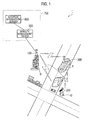
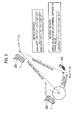
- Fig. 1 is a diagram showing a schematic configuration of a radio communication system 1 according to the first embodiment.
- the radio communication system 1 includes: a radio base station 100; a radio terminal 200; and a relay node 300 (radio relay station).
- the radio communication system 1 is configured based, for example, on LTE-Advanced which is positioned as a fourth-generation (4G) mobile system.
- the radio base station 100 is a macro base station which forms a cell having a radius of around several hundred meters, for example.
- the cell formed by the radio base station 100 indicates a communication area in which connection with the radio base station 100 can be achieved.
- the radio base station 100 is installed in a building B and is immovable.
- the radio base station 100 is connected to an unillustrated backhaul network.
- the backhaul network is a wired communication network.
- the radio base station 100 can communicate with another radio base station via the backhaul network.
- the radio terminal 200 and the relay node 300 are located in the cell formed by the radio base station 100.
- the radio terminal 200 and the relay node 300 are connected to the radio base station 100 by radio.
- the radio terminal 200 is held by a user U and is moved along with the movement of the user U.
- the radio terminal 200 may be a mobile terminal or may be a card-type communication terminal.
- the radio terminal 200 is connected to the radio base station 100 and performs radio communications directly with the radio base station 100.
- the radio terminal 200 executes handover which is a connection target change operation.
- the radio terminal 200 is capable of executing not only handover from one radio base station to another radio base station but also handover from one radio base station to one relay node.
- the radio terminal 200 measures the radio quality of a radio signal received.
- examples of the radio quality include the received power of a reference signal (RSRP) transmitted periodically and the received quality of the reference signal (RSRQ).
- the radio terminal 200 measures not only the radio quality of a radio signal received from the connection target radio base station 100 but also the radio quality of a receivable radio signal.
- the radio terminal 200 measures the radio quality regularly. Alternatively, the radio terminal 200 may measure the radio quality when the level of the radio quality between itself and the connection target radio base station 100 falls below a predetermined level, for example.
- a radio signal that the radio terminal 200 receives includes an identifier (cell ID) for identifying where the radio signal is transmitted from.
- the radio terminal 200 reports a result of the radio quality measurement to the radio base station 100 together with the cell ID. Such a report is referred to as a measurement report in LTE.
- the relay node 300 is installed in transportation equipment T and moves along with the movement of the transportation equipment T.
- a bus is shown as an example of the transportation equipment T.
- the relay node 300 is a low-power output relay base station connected to the radio base station 100 by radio and having a radio backhaul.
- the relay node 300 relays communications between the radio terminal 200 and the radio base station 100.
- the radio terminal 200 communicates directly with the radio base station 100 via the relay node 300.
- the radio base station 100 has a right to decide whether to perform handover in the radio terminal 200 connected to the radio base station 100. Upon receiving a handover instruction from the radio base station 100, the radio terminal 200 executes handover to a handover target specified by the radio base station 100.
- the radio base station 100 knows a radio status of the radio terminal 200 based on the measurement report received from the radio terminal 200, and if handover to another radio base station is necessary, the radio base station 100 transmits a handover request to a handover target candidate radio base station via the backhaul network. Then, the radio base station 100 receives a response from the handover target candidate radio base station. If the handover target candidate radio base station is capable of accepting the radio terminal 200, the radio base station 100 transmits a handover instruction to the radio terminal 200. The radio terminal 200 disconnects the connection with the radio base station 100 and is then connected to the handover target radio base station, thereby completing handover.
- E-UTRA Evolved Universal Terrestrial Radio Access
- E-UTRAN Evolved Universal Terrestrial Radio Access Network
- Figure 10.1.2.1.1-1 Intra-MME/Serving Gateway HO for details of such procedures .
- the radio base station 100 knows the radio status of the radio terminal 200 based on the measurement report received from the radio terminal 200, and if handover to the relay node 300 is necessary, the radio base station 100 transmits a handover request to the handover target candidate relay node 300. Then, the radio base station 100 receives a response from the handover target candidate relay node 300. If the handover target candidate relay node 300 is capable of accepting the radio terminal 200, the radio base station 100 transmits a handover instruction to the radio terminal 200. The radio terminal 200 disconnects the connection with the radio base station 100 and is then connected to the handover target relay node 300, thereby completing handover.
- a radio signal which is transmitted by the relay node 300 mounted on the transportation equipment T reaches the outside of the transportation equipment T.
- the relay node 300 becomes a handover target candidate for the radio terminal 200 connected to the radio base station 100 outside the transportation equipment T if the radio quality level of the radio signal received from the relay node 300 is equal to or higher than a predetermined level.
- the relay node 300 becomes a handover target candidate for the radio terminal 200.
- the radio terminal 200 executes handover to the relay node 300 installed in the transportation equipment T
- the radio terminal 200 needs to execute handover from the relay node 300 to the radio base station 100 as soon as the radio terminal 200 or the relay node 300 is then moved because a communication area formed by the relay node 300 is small.
- the radio terminal 200 is located near the transportation equipment T being stopped waiting for a traffic signal to change.
- the radio terminal 200 executes handover from the radio base station 100 to the relay node 300
- the radio terminal 200 needs to execute handover from the relay node 300 to the radio base station 100 as soon as the transportation equipment T restarts its movement.
- the handover from the radio base station 100 to the relay node 300 proves to be unnecessary.
- connection with the relay node 300 enables the radio terminal 200 to communicate with the radio base station 100 with a better condition than direct connection with the radio base station 100. More specifically, because having a more advanced radio communication function than the radio terminal 200, the relay node 300 is capable of performing better communications with the radio base station 100. Moreover, because this connection enables the radio terminal 200 to perform radio communications with less transmitted power, the radio terminal 200 can reduce its battery consumption.
- the radio base station 100 controls handover from the radio base station 100 to the relay node 300 based on whether or not a state where there is no or small change in the relative distance between the radio terminal 200 and the relay node 300 is kept. If the state where there is no or small change in the relative distance therebetween is kept, the radio terminal 200 can be regarded as located in the transportation equipment T. By contrast, if the state where there is no or small change in the relative distance therebetween is not kept, the radio terminal 200 can be regarded as located outside the transportation equipment T.
- a core network 700 includes: a mobility management device 500 being an upper-level device of the radio base station 100; and a location information server 600 that manages location information.
- the mobility management device 500 is referred to as the MME (Mobility Management Entity) and the location information server 600 is referred to as the E-SMLC (Evolved Serving Mobile Location Centre).
- MME Mobility Management Entity
- E-SMLC Evolved Serving Mobile Location Centre
- the location information server 600 generates location information on the radio terminal 200 and location information on the relay node 300 by collecting differences in arrival time of radio signals that each of the radio terminal 200 and the relay node 300 receives from multiple radio base stations, base station IDs included in the radio signals, and the like, and manages these pieces of location information.
- Non-patent Document 1 for details of the location information server 600 (E-SMLC).
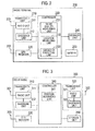
- Fig. 2 is a block diagram showing a configuration of the radio terminal 200.
- the radio terminal 200 includes: an antenna 201; an antenna 202; a transceiver unit 210; a GPS receiver 220; a controller 230; a storage unit 240; and a battery 250.
- the transceiver unit 210 includes: a radio unit 211 that processes signals in a radio frequency band (i.e., radio signals); and a baseband unit 212 that processes signals in a baseband.
- the transceiver unit 210 exchanges radio signals with the radio base station 100 or with the relay node 300 through the antenna 201.
- the GPS receiver 220 receives a signal from a GPS satellite through the antenna 202.
- the controller 230 includes a CPU, for example, and controls various functions that the radio terminal 200 has.
- the storage unit 240 includes a memory, for example, and stores various kinds of information used for, for example, the control of the radio terminal 200.
- the battery 250 stores power to be supplied to the blocks of the radio terminal 200.
- the controller 230 includes: a radio quality measuring unit 231; a location measuring unit 232; and a handover executing unit 233.
- the radio quality measuring unit 231 regularly or irregularly measures the radio quality of a radio signal that the transceiver unit 210 receives.
- the transceiver unit 210 transmits, to the radio base station 100, a report on the result of measurement made by the radio quality measuring unit 231.
- the radio quality is RSRP, RSRQ, or the like, as described previously.
- the transceiver unit 210 may transmit the radio base station 100 a value of RSRP, RSRQ, or the like itself, or instead, an index of RSRP, RSRQ, or the like.
- the location measuring unit 232 measures the location of the radio terminal 200 based on the signal that the GPS receiver 220 receives.
- the transceiver unit 210 transmits, to the radio base station 100, a report on the result of positioning made by the location measuring unit 232.
- the handover executing unit 233 executes handover to a handover target specified by a handover instruction, when the transceiver unit 210 receives the handover instruction.
- the radio terminal 200 does not have the antenna 202, the GPS receiver 220, and the location measuring unit 232. In this case, the radio terminal 200 is not capable of acquiring location information by itself.
- Information on such positioning capability is stored in the storage unit 240 of the radio terminal 200 in advance.
- the controller 230 of the radio terminal 200 Upon request of the radio base station 100, the controller 230 of the radio terminal 200 performs control such that the transceiver unit 210 transmits, to the radio base station 100, the information on the positioning capability stored in the storage unit 240.
- Fig. 3 is a block diagram showing a configuration of the relay node 300.
- the relay node 300 includes: an antenna 301; an antenna 302; an antenna 303; a transceiver unit 310; a transceiver unit 320; a GPS receiver 330; a controller 340; and a storage unit 350.
- the transceiver unit 310 includes: a radio unit 311 that processes radio signals; and a baseband unit 312 that processes baseband signals.
- the transceiver unit 310 exchanges radio signals with the radio base station 100 through the antenna 301.
- the transceiver unit 320 includes: a radio unit 321 that processes radio signals; and a baseband unit 322 that processes baseband signals.
- the transceiver unit 320 exchanges radio signals with the radio terminal 200 through the antenna 302.
- a single antenna may be used both as the antennas 301 and 302, and a single transceiver unit may be used both as the transceiver units 310 and 320; in this case, a function to control switching between transceiver is required.
- the GPS receiver 330 receives a signal from a GPS satellite through the antenna 303.
- the controller 340 includes a CPU, for example, and controls various functions that the relay node 300 has.
- the storage unit 350 includes amemory, for example, and stores various kinds of information used for, for example, the control of the relay node 300.
- the controller 340 includes a position measuring unit 341.
- the location measuring unit 341 measures the location of the relay node 300 based on the signal that the GPS receiver 330 receives.
- the transceiver unit 310 transmits, to the radio base station 100, a report on the result of positioning made by the location measuring unit 341.
- the relay node 300 does not have the antenna 303, the GPS receiver 330, and the location measuring unit 341. In this case, the relay node 300 is not capable of acquiring location information by itself.
- Information on such positioning capability is stored in the storage unit 350 of the relay node 300 in advance.
- the controller 340 of the relay node 300 Upon request of the radio base station 100, the controller 340 of the relay node 300 performs control such that the transceiver unit 310 transmits, to the radio base station 100, the information on the positioning capability stored in the storage unit 350.
- Fig. 4 is a block diagram showing a configuration of the radio base station 100.
- the radio base station 100 includes: an antenna 101; a transceiver unit 110; a controller 120; a backhaul communication unit 130; and a storage unit 140.
- the transceiver unit 110 includes: a radio unit 111 that processes radio signals; and a baseband unit 112 that processes baseband signals.
- the transceiver unit 110 exchanges radio signals with the radio terminal 200 or with the relay node 300 through the antenna 101.
- the controller 120 includes a CPU, for example, and controls various functions that the radio base station 100 has.
- the backhaul communication unit 130 communicates with another radio base station via the backhaul network.
- the storage unit 140 includes a memory, for example, and stores various kinds of information used for, for example, the control of the radio base station 100.
- the controller 120 includes: a capability information acquiring unit 121; a capability determining unit 122; a location information acquiring unit 123; a moving distance calculating unit 124; a relative distance calculating unit 125; and a handover controller 126.
- the capability information acquiring unit 121 acquires information on the positioning capability of the radio terminal 200 being connected to the radio base station 100 (hereinafter terminal capability information) and information on the positioning capability of the relay node 300 being connected to the radio base station 100 (hereinafter relay node capability information).
- the capability determining unit 122 determines whether or not location information of the radio terminal 200 being connected to the radio base station 100 is acquirable from the radio terminal 200 based on the terminal capability information. Moreover, the capability determining unit 122 determines whether or not location information of the relay node 300 being connected to the radio base station 100 is acquirable from the relay node 300 based on the relay node capability information.
- the location information acquiring unit 123 acquires location information from each of the radio terminal 200 and the relay node 300 if it is determined that the location information is acquirable from each of the radio terminal 200 and the relay node 300. More specifically, the location information acquiring unit 123 acquires the location information of the radio terminal 200 based on the report on the measurement result that the transceiver unit 110 receives from the radio terminal 200. Moreover, the location information acquiring unit 123 acquires the location information of the relay node 300 based on the report on the measurement result that the transceiver unit 110 receives from the relay node 300.
- the moving distance calculating unit 124 calculates a value indicating a moving distance of the radio terminal 200 in a predetermined time period, and a value indicating a moving distance of the relay node 300 in the predetermined time period.
- the moving distance calculation operation of the moving distance calculating unit 124 is described in detail later.
- the relative distance calculating unit 125 calculates a value indicating the change in the relative distance between the radio terminal 200 and the relay node 300 in the predetermined time period, on the basis of the location information that the location information acquiring unit 123 acquires.
- the relative distance calculating unit 125 is equivalent to a first calculation unit. The relative distance calculation operation of the relative distance calculating unit 125 is described in detail later.
- the handover controller 126 performs handover-related control. For example, the handover controller 126 decides a handover target and generates handover-related messages.
- the handover controller 126 If the value indicating the change in the relative distance between the radio terminal 200 and the relay node 300 and calculated by the relative distance calculating unit 125 is equal to or smaller than a threshold, the handover controller 126 generates a message instructing the radio terminal 200 to execute handover from the radio base station 100 to the relay node 300. The transceiver unit 110 transmits the message to the radio terminal 200. If the value indicating the change in the relative distance therebetween is larger than the threshold, the handover controller restricts handover from the radio base station 100 to the relay node 300 executed by the radio terminal 200. The handover control operation of the handover controller 126 is described in detail later.
- the controller 120 performs control such that the transceiver unit 110 transmits, to the radio terminal 200 connected to the radio base station 100, a Capability Request message requesting a transmission of terminal capability information indicating the positioning capability of the radio terminal 200 (capability information transmission request). If the relay node 300 is a handover candidate for the radio terminal 200, the controller 120 performs control such that the transceiver unit 110 transmits, to the relay node 300 connected to the radio base station 100, a Capability Request message requesting a transmission of terminal capability information indicating the positioning capability of the relay node 300.
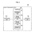
- Fig. 5 is a block diagram showing a configuration of the mobility management device 500.
- the mobility management device 500 includes: a transceiver unit 510; a controller 520; and a storage unit 530.
- the transceiver unit 510 is connected to the backhaul network, and communicates with the radio base station 100 and with the location information server 600 via the backhaul network.
- the transceiver unit 510 receives from the location information server 600 the location information of the radio terminal 200 and the location information of the relay node 300.
- the controller 520 includes a CPU, for example, and controls various functions that the mobility management device 500 has.
- the storage unit 530 includes a memory, for example, and stores various kinds of information used for, for example, the control of the mobility management device 500.
- the controller 520 includes: an information acquiring unit 521; a moving distance calculating unit 522; a relative distance calculating unit 523; and a handover judging unit 524.
- the information acquiring unit 521 acquires the location information that the transceiver unit 510 receives from the location information server 600.
- the moving distance calculating unit 522 calculates values indicating moving distances of the radio terminal 200 and the relay node 300 in the predetermined time period. The moving distance calculation operation of the moving distance calculating unit 522 is described in detail later.
- the relative distance calculating unit 523 calculates a value indicating the change in the relative distance between the radio terminal 200 and the relay node 300 in the predetermined time period, on the basis of the location information that the information acquiring unit 521 acquires.
- the relative distance calculation operation of the relative distance calculating unit 523 is described in detail later.
- the handover judging unit 524 makes handover-related judgment. More specifically, the handover judging unit 524 judges whether or not to allow the radio terminal 200 to execute handover to the relay node 300.
- the radio base station 100 or the mobility management device 500 acquires location information of the radio terminal 200 and location information of the relay node 300, and controls the handover of the radio terminal 200 by using the acquired location information.
- Such handover control operation is described below in the following order: (1.2.1.1) First Operation Example; (1.2.1.2) Second Operation Example; and (1.2.1.3) Third Operation Example.
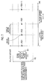
- Figs. 6 and 7 are diagrams for describing a first operation example of the handover control operation.
- the radio base station 100 or the mobility management device 500 acquires location information A (X1, Y1, Z1) of the relay node 300 and location information B (X2, Y2, Z2) of the radio terminal 200 at timing 0 in a state where the level of the radio quality between the radio terminal 200 and the relay node 300 is higher than the level of the radio quality between the radio terminal 200 and the radio base station 100.
- location information is defined by the X, Y, and Z coordinates here, the Z coordinate (vertical direction) does not necessarily have to be included in the location information.
- the radio base station 100 or the mobility management device 500 acquires location information A' (X1', Y1', Z1') of the relay node 300 and location information B' (X2', Y2', Z2') of the radio terminal 200 at timing t, after a lapse of a predetermined time period since the timing 0, in the state where the level of the radio quality between the radio terminal 200 and the relay node 300 is higher than the level of the radio quality between the radio terminal 200 and the radio base station 100.
- the radio base station 100 or the mobility management device 500 calculates a A-A' distance as a moving distance of the relay node 300 (MDA) and calculates a B-B' distance as a moving distance of the radio terminal 200 (MDB) by using a formula described in Fig. 6 .
- the radio base station 100 or the mobility management device 500 calculates a A-B relative distance 1 (RD1) and calculates a A'-B' relative distance 2 (RD2) in accordance with a formula described in Fig. 6 .
- the radio base station 100 or the mobility management device 500 then calculates a difference between the relative distance 1 (RD1) and the relative distance 2 (RD2) (
- the radio base station 100 transmits, to the radio terminal 200, an instruction of handover from the radio base station 100 to the relay node 300.
- the radio terminal 200 executes handover from the radio base station 100 to the relay node 300.
- the radio base station 100 or the mobility management device 500 acquires location information A" (X1'', Y1'', Z1'') of the relay node 300 and location information B'' (X2'', Y2'', Z2'') of the radio terminal 200 at timing 2t, after a lapse of a predetermined time period since the timing t, in the state where the level of the radio quality between the radio terminal 200 and the relay node 300 is higher than the level of the radio quality between the radio terminal 200 and the radio base station 100.
- the radio base station 100 or the mobility management device 500 calculates an A-A'' distance as a moving distance of the relay node 300 (MDA' ) and calculates a B-B'' distance as a moving distance of the radio terminal 200 (MDB' ). If at least one of the moving distance of the relay node 300 (MDA') and the moving distance of the radio terminal 200 (MDB') is larger than zero, the radio base station 100 or the mobility management device 500 calculates a A-B relative distance 1 (RD1) and calculates an A''-B'' relative distance 2 (RD2').
- RD1 A-B relative distance 1
- RD2' A''-B'' relative distance 2
- the radio base station 100 or the mobility management device 500 then calculates a difference between the relative distance 1 (RD1) and the relative distance 2 (RD2') (
- RD1 relative distance 1
- RD2' relative distance 2
- the radio base station performs control to make the radio terminal 200 execute handover from the radio base station 100 to the relay node 300 when the level of the radio quality between the radio terminal 200 and the relay node 300 is higher than the level of the radio quality between the radio terminal 200 and the radio base station 100 and when the value of the change (difference) in the relative distance is equal to or smaller than the threshold.
- the radio base station 100 performs control not to make the radio terminal 200 execute handover (to restrict handover of the radio terminal 200) from the radio base station 100 to the relay node 300 even when the level of the radio quality between the radio terminal 200 and the relay node 300 is higher than the level of the radio quality between the radio terminal 200 and the radio base station 100.
- Such handover control makes it possible to make the radio terminal 200 execute handover to the relay node 300 when the radio terminal 200 is located in the transportation equipment T and not execute handover to the relay node 300 when the radio terminal 200 is not located in the transportation equipment T.
- the value of the change (difference) in the relative distance is calculated when at least one of the moving distances of the radio terminal 200 and the relay node 300 is larger than zero. This is because it is difficult to judge whether or not the radio terminal 200 is located in the transportation equipment T when the moving distances of the radio terminal 200 and the relay node 300 are both equal to zero. Thereby, whether or not the radio terminal 200 is located in the transportation equipment T is judged more accurately.
- Fig. 8 is a diagram for describing a second operation example of the handover control operation.
- the radio base station 100 or the mobility management device 500 acquires location information A (X1, Y1, Z1) of the relay node 300 at a first time point where the radio quality between the radio terminal 200 and the relay node 300 is at such a level that the radio terminal 200 is connectable to the relay node 300.
- the state where the radio terminal 200 is connectable to the relay node 300 denotes, for example, a state where the level of the radio quality between the radio terminal 200 and the relay node 300 is higher than the level of the radio quality between the radio terminal 200 and the radio base station 100.
- the radio base station 100 or the mobility management device 500 acquires location information A' (X1', Y1', Z1') of the relay node 300 and location information B (X2, Y2, Z2) of the radio terminal 200 at a second time point after a lapse of a predetermined time period since the first time point.
- the radio base station 100 or the mobility management device 500 calculates a A-A' distance as a moving distance of the relay node 300 (MDA) by using a formula described in Fig. 8 .
- the radio base station 100 or the mobility management device 500 calculates a A'-B relative distance (RD) at the second time point by using a formula described in Fig. 8 .
- RD A'-B relative distance
- This example differs from the first operation example above in that the relative distance between the radio terminal 200 and the relay node 300 at the first time point is regarded as zero in this process. More specifically, because the transmitted power of the relay node 300 is small, it is possible to estimate that the radio terminal 200 is located near the relay node 300 if the radio terminal 200 is connectable to the relay node 300. Accordingly, the relative distance between the radio terminal 200 and the relay node 300 at the first time point can be regarded as zero.
- the A'-B relative distance (RD) indicates the change in the relative distance between the radio terminal 200 and the relay node 300 in a predetermined time period (from the first time point to the second time point).
- the radio base station 100 or the mobility management device 500 makes a judgment to allow (accept) handover of the radio terminal 200 from the radio base station 100 to the relay node 300.
- the threshold is a value corresponding to a predetermined distance from the relay node 300 (an area equivalent to the inside of the transportation equipment T, for example), as shown by a circle about the relay node 300 in Fig. 8 .
- the radio base station 100 instructs the radio terminal 200 to execute handover to the relay node 300 if allowing the handover.
- the radio base station 100 or the mobility management device 500 acquires location information A'' (X1'', Y1'', Z1'') of the relay node 300 at a third time point after a lapse of a predetermined time period since the second time point. In this manner, the radio base station 100 or the mobility management device 500 iterates the acquisition of the location information of the relay node 300 for a predetermined number of times if the moving distance (MDA) of the relay node 300 is equal to zero.
- Such handover control makes it possible to make the radio terminal 200 execute handover to the relay node 300 when the radio terminal 200 is located in the transportation equipment T and not execute handover to the relay node 300 when the radio terminal 200 is not located in the transportation equipment T, as in the first operation example.
- Fig. 9 is a diagram for describing a third operation example of the handover control operation.
- the radio base station 100 or the mobilitymanagement device 500 acquires location information A (X1, Y1, Z1) of the relay node 300 at a first time point where the radio quality between the radio terminal 200 and the relay node 300 is at such a level that the radio terminal 200 is connectable to the relay node 300.
- the state where the radio terminal 200 is connectable to the relay node 300 denotes, for example, a state where the level of the radio quality between the radio terminal 200 and the relay node 300 is higher than the level of the radio quality between the radio terminal 200 and the radio base station 100.
- the radio base station 100 or the mobility management device 500 acquires location information A' (X1', Y1', Z1') of the relay node 300 and location information B (X2, Y2, Z2) of the radio terminal 200 at a second time point after a lapse of a predetermined time period since the first time point.
- the radio base station 100 or the mobility management device 500 calculates a A-A' distance as a moving distance of the relay node 300 (MDA) and calculates a A-B distance as a moving distance of the radio terminal 200 (MDB) by using a formula described in Fig. 9 .
- MDA moving distance of the relay node 300
- MDB moving distance of the radio terminal 200
- This example differs from the first operation example above in that the relative distance between the radio terminal 200 and the relay node 300 at the first time point is regarded as zero and the location of the radio terminal 200 at the first time point is regarded as equal to the location of the relay node 300 in this process. More specifically, because the transmitted power of the relay node 300 is small, it is possible to estimate that the radio terminal 200 is located near the relay node 300 if the radio terminal 200 is connectable to the relay node 300. Accordingly, the relative distance between the radio terminal 200 and the relay node 300 at the first time point can be regarded as zero.
- the radio base station 100 or the mobility management device 500 calculates a A' -B relative distance (RD) at the second time point by using a formula described in Fig. 9 . Because the relative distance between the radio terminal 200 and the relay node 300 at the first time point is regarded as zero, the A'-B relative distance (RD) thus calculated indicates the change in the relative distance between the radio terminal 200 and the relay node 300 in a predetermined time period (from the first time point to the second time point).
- the radio base station 100 or the mobility management device 500 makes a judgment to allow (accept) handover of the radio terminal 200 from the radio base station 100 to the relay node 300.
- the threshold is a value corresponding to a predetermined distance from the relay node 300 (an area equivalent to the inside of the transportation equipment T, for example), as shown by a circle about the relay node 300 in Fig. 9 .
- the radio base station 100 instructs the radio terminal 200 to execute handover to the relay node 300 if allowing the handover.
- the radio base station 100 or the mobility management device 500 acquires location information A'' (X1'', Y1'', Z1'') of the relay node 300 and location information B' (X2', Y2', Z2') of the radio terminal 200 at a third time point after a lapse of a predetermined time period since the second time point.
- the radio base station 100 or the mobility management device 500 iterates the acquisition of the location information of the relay node 300 and the location information of the radio terminal 200 for a predetermined number of times if the moving distance (MDA) of the relay node 300 and the moving distance (MDB) of the radio terminal 200 are equal to zero.
- Such handover control makes it possible to make the radio terminal 200 execute handover to the relay node 300 when the radio terminal 200 is located in the transportation equipment T and not execute handover to the relay node 300 when the radio terminal 200 is not located in the transportation equipment T, as in the first operation example.
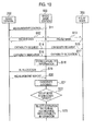
- Fig. 10 is a sequence diagram showing an overall schematic operation of the radio communication system 1 according to the first embodiment. It is assumed here that each of the radio terminal 200 and the relay node 300 connected to the radio base station 100 is currently performing communications (in the RRC Connected state).
- Step S11 the radio base station transmits, to the radio terminal 200, information on Measurement Control over the radio quality in the radio terminal 200.
- Steps S12 and S13 the radio base station 100 exchanges packet data other than control data used for communication control, with the radio terminal 200 and the relay node 300.
- the packet data exchange continues in later processes as well.
- Step S14 the radio base station 100 transmits, to the radio terminal 200, a Capability Request message requesting a transmission of terminal capability information indicating the positioning capability of the radio terminal 200 (capability information transmission request).
- Step S15 the radio base station 100 transmits, to the relay node 300, a Capability Request message requesting a transmission of terminal capability information indicating the positioning capability of the relay node 300 (capability information transmission request).
- Step S16 the radio terminal 200 transmits, to the radio base station 100, a Capability Indication message indicating the positioning capability of the radio terminal 200 (terminal capability information) in response to the Capability Request message from the radio base station 100.
- Step S17 the relay node 300 transmits, to the radio base station 100, a Capability Indication message indicating the positioning capability of the relay node 300 (relay station capability information) in response to the Capability Request message from the radio base station 100.
- Step S18 the radio base station 100 stores the capability information indicated by the Capability Indication message from the radio terminal 200 and the capability information indicated by the Capability Indication message from the relay node 300.
- Step S19 the radio base station 100 allocates a radio resource to the radio terminal 200, the radio resource being used for a report on a result of radio quality measurement made in the radio terminal 200.
- the radio base station 100 then transmits, to the radio terminal 200, information on the allocation result (UL allocation).
- Step S20 the radio terminal 200 measures the radio quality of a received radio signal and transmits, to the radio base station 100, a Measurement Report message indicating the measurement result, under control of the radio base station 100.
- Step S21 the radio base station 100 judges whether or not making the radio terminal 200 execute handover is necessary based on the Measurement Report message from the radio terminal 200.
- the radio base station 100 compares the radio quality of the radio base station 100 and the radio quality of a different node (a different radio base station or the relay node 300), and judges that making the radio terminal 200 execute handover is necessary if the radio quality of the different node is better than the radio quality of the radio base station 100.
- Step S22 the radio base station 100 judges whether or not a handover target for the radio terminal 200 is the relay node 300.
- the radio base station 100 judges whether or not the handover target is the relay node 300 based on a cell ID included in the Measurement Report message. If the handover target is the relay node 300, the process moves to the following process.
- Step S23 the radio base station 100 determines whether or not the location information of the radio terminal 200 is acquirable from the radio terminal 200 and whether or not the location information of the relay node 300 is acquirable from the relay node 300, based on the capability information stored in Step S18.
- the first operation pattern is an operation pattern where the handover control according to any one of the above-described first to third operation examples is performed mainly by the radio base station 100.
- the second operation pattern is an operation pattern where the handover control according to any one of the above-described first to third operation examples is performed mainly by the mobility management device 500.
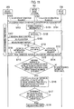
- Fig. 11 is an operation sequence diagram showing the first operation pattern of the radio communication system 1 according to the first embodiment. It is assumed here that the handover control operation according to the first operation example is performed.
- Step S101 the radio base station 100 transmits, to the radio terminal 200, a location information request to transmit information on a measurement result.
- Step S102 the radio base station 100 transmits, to the relay node 300, a location information request to transmit information on a measurement result.
- Step S103 upon receiving the location information request, the radio terminal 200 performs positioning and transmits, to the radio base station 100, a location information report indicating the positioning result.
- Step S104 upon receiving the location information request, the relay node 300 performs positioning and transmits, to the radio base station 100, a location information report indicating the positioning result.
- Step S105 the radio base station 100 stores location information of the radio terminal 200 based on the location information report from the radio terminal 200. Besides, the radio base station 100 stores location information of the relay node 300 based on the location information report from the relay node 300.
- Step S106 the radio base station 100 counts a specified time period.
- Step S107 the radio base station 100 transmits information on Measurement Control to the radio terminal 200.
- Step S108 the radio base station 100 allocates a radio resource to the radio terminal 200, the radio resource being used for a report on a result of radio quality measurement made in the radio terminal 200.
- the radio base station 100 then transmits allocation information (UL allocation) to the radio terminal 200.
- Step S109 the radio terminal 200 measures the radio quality of a received radio signal and transmits a measurement report (Measurement Report message) to the radio base station 100, under control of the radio base station 100.
- Step S110 the radio base station 100 judges whether or not making the radio terminal 200 execute handover is necessary based on the measurement report which is received from the radio terminal 200 in Step S115.
- the radio base station 100 compares the radio quality of the radio base station 100 and the radio quality of the relay node 300, and judges that making the radio terminal 200 execute handover to the relay node 300 is necessary if the radio quality of the relay node 300 is better than the radio quality of the radio base station 100. If the radio base station 100 judges that making the radio terminal 200 execute handover to the relay node 300 is necessary, the process moves to the following process.
- Step S111 the radio base station 100 transmits a location information request to the radio terminal 200.
- Step S112 the radio base station 100 transmits a location information request to the relay node 300.
- Step S113 upon receiving the location information request, the radio terminal 200 performs positioning again and transmits a location information report indicating the positioning result to the radio base station 100.
- Step S114 upon receiving the location information request, the relay node 300 performs positioning again and transmits a location information report indicating the positioning result to the radio base station 100.
- a predetermined time period is defined as a time period for the radio base station 100 to receive the location information report from each of the radio terminal 200 and the relay node 300 again upon re-requesting location information since last receiving the location information report from each of the radio terminal 200 and the relay node 300.
- Step S115 the radio base station 100 calculates a moving distance of the radio terminal 200 and a moving distance of the relay node 300. If the moving distances of the radio terminal 200 and the relay node 300 are both equal to zero, the process returns to Step S106. Note that the number of times the radio base station 100 can iterate this process is limited and is set to a predetermined number of times (see Fig. 7 ) . If at least one of the moving distance of the radio terminal 200 and the moving distance of the relay node 300 is larger than zero, the process moves to Step S116.
- Step S116 the radio base station 100 calculates a relative distance 1 based on the location information of the radio terminal 200 and the location information of the relay node 300 stored in Step S105, and calculates a relative distance 2 based on the location information report received in Steps S113 and S114. Then, the radio base station 100 calculates a difference between the relative distance 1 and the relative distance 2.
- Step S117 if the difference between the relative distance 1 and the relative distance 2 is equal to or smaller than a threshold, in Step S118 the radio base station 100 decides handover from the radio base station to the relay node 300 and transmits, to the radio terminal 200, an instruction of handover from the radio base station 100 to the relay node 300. On the other hand, if the difference between the relative distance 1 and the relative distance 2 is larger than the threshold in Step S117, the radio base station 100 cancels handover from the radio base station 100 to the relay node 300.
- Fig. 12 is an operation sequence diagram showing the second operation pattern of the radio communication system 1 according to the first embodiment. It is assumed here that the handover control operation according to the second or third operation example is performed.
- Step S201 the radio base station 100 transmits a handover request message to the relay node 300.
- the radio base station 100 may transmit a judgment request message, which requests judgment on handover, to the mobility management device 500 without transmitting the handover request message to the relay node 300.
- Step S202 in response to the handover request message from the radio base station 100, the relay node 300 transmits a judgment request message to the mobility management device 500 to ask the core network 700 to make judgment on handover. Since the connection between the relay node 300 and the core network 700 is made by way of the radio base station 100, the radio base station 100 can recognize transmitting of the judgment request message to the mobility management device 500.
- Step S203 the radio base station 100 stops a handover-related timer when the judgment request message to the mobility management device 500 passes the radio base station 100. Note that, after a predetermined time period, the radio base station 100 performs a process for enabling a request to the radio terminal 200 for radio quality measurement.
- Step S204 the mobility management device 500 receives the judgment request message.
- Step S205 the mobility management device 500 transmits, to the location information server 600, a location information request message requesting location information of the relay node 300.
- the location information server 600 measures the location information of the relay node 300 in response to the location information request message.
- Step S208 the location information server 600 transmits the result of location information measurement to the mobility management device 500.
- Step S209 the mobility management device 500 holds the location information of the relay node 300.
- Step S210 the mobility management device 500 waits for a lapse of a predetermined interval.
- Step S211 the mobility management device 500 transmits, to the location information server 600, a location information request message requesting location information of the relay node 300 and location information of the radio terminal 200.
- Steps S212 to S214 upon receiving the location information request message, the location information server 600 measures location information of the relay node 300 and location information of the radio terminal 200.
- Step S215 the location information server 600 transmits the result of location information measurement to the mobility management device 500.
- a predetermined time period is defined as a time period for the location information notice (Step S208) from the location information server 600 to arrive at the mobility management device 500 again since the location information notice (Step S215) from the location information server 600 arrives at the mobility management device 500 first.
- Step S2108 the mobility management device 500 calculates a moving distance in accordance with the above operation examples.
- the process returns to Step S209 and Steps S209 to S215 are iterated if the moving distance of the relay node 300 is equal to 0.
- the process returns to Step S209 and Steps S209 to S215 are iterated if the moving distance of the radio terminal 200 and the moving distance of the relay node 300 are equal to 0. Note that the number of times the mobility management device 500 can iterate this process is limited and is set to a predetermined number of times.
- the mobility management device 500 calculates a relative distance based on the location information of the radio terminal 200 and the location information of the relay node 300 if judging that the moving distance of the relay node 300 is not equal to 0; in the case of the third operation example, the mobility management device 500 calculates a relative distance based on the location information of the radio terminal 200 and the location information of the relay node 300 if the moving distance of the radio terminal 200 and the moving distance of the relay node 300 are not equal to 0.
- the mobility management device 500 makes a judgment to allow (accept) handover of the radio terminal 200 from the radio base station 100 to the relay node 300. If the calculated relative distance is equal to or larger than the threshold, the mobility management device 500 makes a judgment to reject (deny) handover of the radio terminal 200 from the radio base station 100 to the relay node 300.
- Step S219 the mobility management device 500 transmits information on the judgment result to the radio base station 100.
- Step S216 the radio base station 100 allocates a resource to the radio terminal 200 so that the radio terminal 200 can notify the radio base station 100 of the result of radio quality measurement.
- Step S217 the radio terminal 200 notifies the radio base station 100 of the result of radio quality measurement in accordance with an instruction from the radio base station 100.
- the measurement result includes information on the radio quality between the radio terminal 200 and the relay node 300.
- Step S220 the radio base station 100 decides whether or not to make the radio terminal 200 execute handover from the radio base station 100 to the relay node 300 based on the information on the judgment result received from the mobility management device 500 in Step S219 and on the measurement result received from the radio terminal 200 in Step S217.
- the radio base station 100 decides to make the radio terminal 200 execute handover from the radio base station 100 to the relay node 300 if the handover is judged as allowable (acceptable) by the mobility management device 500 and if the radio quality between the radio terminal 200 and the relay node 300 is good. If deciding to make the radio terminal 200 execute handover, the radio base station 100 checks whether or not the relay node 300 is capable of accepting the radio terminal 200, and then transmits, to the radio terminal 200, an instruction of handover to the relay node 300.
- the radio base station 100 performs control not to make the radio terminal 200 execute handover from the radio base station 100 to the relay node 300 even when the level of the radio quality between the radio terminal 200 and the relay node 300 is higher than the level of the radio quality between the radio terminal 200 and the radio base station 100.
- Such handover control makes it possible to make the radio terminal 200 execute handover to the relay node 300 when the radio terminal 200 is located in the transportation equipment T and not execute handover to the relay node 300 when the radio terminal 200 is not located in the transportation equipment T.
- the occurrence of the processing load and communication delay due to unnecessary handover can be prevented.
- the overhead due to handover from the radio base station 100 to the relay node 300 is larger than the overhead due to handover from one radio base station to another.
- the first embodiment can reduce the probability of the handover from the radio base station 100 to the relay node 300, and thereby can suppress the overhead.
- the value of the change (difference) in the relative distance is not calculated when the moving distance of the radio terminal 200 and the moving distance of the radio base station 100 are both equal to zero; and the value of the change (difference) in the relative distance is calculated when at least one of the moving distance of the radio terminal 200 and the moving distance of the radio base station 100 is larger than zero.
- the handover controller 126 transmits a location information request to the radio terminal 200 and to the relay node 300 when the level of the radio quality between the radio terminal 200 and the relay node 300 is higher than the level of the radio quality between the radio terminal 200 and the radio base station 100. In other words, the handover controller 126 does not transmit a location information request to the radio terminal 200 and to the relay node 300 when the level of the radio quality between the radio terminal 200 and the relay node 300 is equal to or lower than the level of the radio quality between the radio terminal 200 and the radio base station 100.
- the relative distance between the radio terminal 200 and the relay node 300 is regarded as zero if the handover target is the relay node 300. Thereby, a procedure of measuring location information of the radio terminal 200 upon handover request can be omitted. Accordingly, handover-related calculation can be reduced.
- the handover to the relay node 300 is controlled based on the relative distance between the location of the relay node 300 and that of the radio terminal 200 after a lapse of the predetermined time period. Thereby, a process of calculating the moving distance of the radio terminal 200 can be curtailed.
- the location information measurement is carried out by the core network 700 (specifically, the location information server 600). Accordingly, the first embodiment is applicable also to a case where the radio terminal 200 or the relay node 300 does not have a system, such as GPS, which enables itself to measure its location information. Moreover, control signals among the radio terminal 200, the radio base station 100, and the core network 700 can be reduced, thus reducing the traffic load.
- the core network 700 specifically, the location information server 600.
- the radio base station 100 can select an appropriate operation pattern between the first operation pattern and the second operation pattern described above based on the positioning capability of the radio terminal 200 and the positioning capability of the relay node 300. More specifically, the radio base station 100 knows the positioning capability of the radio terminal 200 and the positioning capability of the relay node 300. The radio base station 100 thereby determines whether or not the location information of the radio terminal 200 is acquirable from the radio terminal 200 itself and whether or not the location information of the relay node 300 is acquirable from the relay node 300 itself.
- the radio base station 100 can omit the process of acquiring the location information of the radio terminal 200 from the location information server 600 if the location information of the radio terminal 200 is acquirable from the radio terminal 200 itself. Moreover, the radio base station 100 can omit the process of acquiring the location information of the relay node 300 from the location information server 600 if the location information of the relay node 300 is acquirable from the relay node 300 itself. Accordingly, according to the first operation pattern 1, no signaling occurs between the radio base station 100 and the location information server 600, and an increase of network traffic can be suppressed.
- the radio transmission environment around a radio base station 100 changes if a building is built near the radio base station 100 or installation conditions of its neighboring radio base stations change after the radio base station 100 is installed.
- MDT automates the acquisition work by using a radio terminal 200 of the user (see 3GPP TR36.805 and TS37.320).
- Fig. 13 is a diagram showing a schematic configuration of a radio communication system 1 according to the second embodiment. Note that, in Fig. 13 , the mobility management device 500 and the location information server 600 described in the first embodiment are not illustrated.
- the radio communication system 1 includes: a radio base station 100; and multiple radio terminals 200.
- the radio communication system 1 is configured based, for example, on LTE-Advanced which is positioned as a fourth-generation (4G) mobile system.
- 4G fourth-generation
- the radio base station 100 is a macro base station which forms a cell having a radius of around several hundredmeters, for example.
- the cell formed by the radio base station 100 indicates a communication area in which connection with the radio base station 100 can be achieved.
- the radio base station 100 is connected to an unillustrated backhaul network.
- Each radio terminal 200 is located in the cell formed by the radio base station 100, and is connected to the radio base station 100 by radio to perform communications.
- the radio terminal 200 is held by a user U and is moved along with the movement of the user U.
- the radio terminal 200 may be a mobile terminal or may be a card-type communication terminal.
- the radio terminal 200 measures the radio quality of a radio signal received.
- examples of the radio quality include the received power of a reference signal (RSRP) transmitted periodically and the received quality of the reference signal (RSRQ).
- the radio terminal 200 measures not only the radio quality of a radio signal received from the connection target radio base station 100 but also the radio quality of a receivable radio signal.
- the radio terminal 200 measures the radio quality regularly.
- the radio terminal 200 may measure the radio quality when the level of the radio quality between itself and the connection target radio base station 100 falls below a predetermined level, for example.
- Some of the radio terminals 200 have a positioning system, such as GPS, which enables the radio terminal 200 itself to measure its location information and the others don't have such a system.
- the radio base station 100 needs to acquire the location information from a location information server 600.
- signaling occurs between the radio base station 100 and the location information server 600.
- the radio base station 100 acquires radio quality information and location information by use of the radio terminal 200. If the radio terminal 200 not having a positioning system such as GPS is used for MDT in this process, this results in an increase of network (backhaul) traffic due to signaling. Moreover, it is not possible to accurately measure the location of a radio terminal in an idle mode. For the above reasons, a radio terminal to be used for MDT is selected based on the location measurement capability (positioning capability) of each radio terminal.
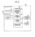
- Fig. 14 is a block diagram showing a configuration of the radio base station 100 according to the second embodiment.
- the radio base station 100 includes: an antenna 101; a transceiver unit 110; a controller 120; a backhaul communication unit 130; and a storage unit 140.
- the transceiver unit 110 includes: a radio unit 111 that processes radio signals; and a baseband unit 112 that processes baseband signals.
- the transceiver unit 110 exchanges radio signals with each radio terminal 200 through the antenna 101.
- the controller 120 includes a CPU, for example, and controls various functions that the radio base station 100 has.
- the backhaul communication unit 130 communicates with another radio base station via the backhaul network.
- the storage unit 140 includes a memory, for example, and stores various kinds of information used for, for example, the control of the radio base station 100.
- the controller 120 includes: a capability information acquiring unit 121; a capability determining unit 122; a terminal selecting unit 127; and a measurement controller 128.
- the capability information acquiring unit 121 acquires information on the positioning capability of each radio terminal 200 being connected to the radio base station 100 (terminal capability information).
- the capability determining unit 122 determines whether or not location information of each radio terminal 200 being connected to the radio base station 100 is acquirable from the radio terminal 200 based on the terminal capability information. The capability determining unit 122 determines, for each of the multiple radio terminals 200, whether or not the radio terminal is capable of acquiring location information by itself based on the terminal capability information from the radio terminal 200.
- the terminal selecting unit 127 selects the radio terminal 200 to be used for the measurement process (MDT) based on the result of judgment made by the capability determining unit 122.
- the measurement controller 128 controls the measurement of radio quality information and location information performed by the radio terminal 200.
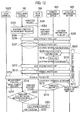
- Fig. 15 is a sequence diagram showing an operation sequence of the radio communication system 1 according to the second embodiment.
- Step S301 the radio base station 100 checks whether or not to start a MDT measurement process.
- the MDT measurement process may be performed regularly, or instead may be performed in response to an instruction from a server of an operator. If the MDT measurement process is to be started, the process moves to Step S302.
- Step S302 the radio base station 100 transmits, to each radio terminal 200, a Capability Request message requesting a transmission of terminal capability information indicating the positioning capability of the radio terminal 200 (capability information transmission request).
- each radio terminal 200 transmits, to the radio base station 100, a Capability Indication message indicating its positioning capability (terminal capability information) in response to the Capability Request message from the radio base station 100.
- Step S304 the radio base station 100 determines what kind of location measurement capability (positioning capability) each radio terminal 200 has, based on the terminal capability information from the radio terminal 200. Then, based on the measurement capability information of each radio terminal 200, the radio base station 100 selects which radio terminal 200 is to be used for the measurement process (MDT).
- location measurement capability positioning capability
- Step S305 the radio base station 100 transmits, to the radio terminal 200 to be used for the measurement process (MDT), information on control over radio quality information/location information measurement (MDT indication).
- MDT measurement process
- MDT indication information on control over radio quality information/location information measurement
- the radio terminal 200 to be used for the measurement process measures the radio quality of a received radio signal and the location as well as transmits the radio base station 100 a Measurement Report message indicating the measurement result upon request from a network, under control of the radio base station 100.
- the radio base station 100 transmits the radio quality information and the location information thus acquired to the server of the operator, or uses them for adjusting communication parameters of the radio base station 100.
- the radio base station 100 selects the radio terminal 200 having the positioning system such as GPS among the multiple radio terminals 200 and uses this in MDT, for example. Thereby, the process of acquiring location information of the radio terminal 200 from the location information server 600 can be omitted. As a result, an increase of network (backhaul) traffic due to signaling between the radio base station 100 and the location information server 600 can be suppressed. In addition, accurate location measurement can be carried out even in the case where MDT is performed using a radio terminal in an idle mode.
- the present invention may be applied to another radio communication system such as a radio communication system based on Mobile WiMAX (IEEE 802.16e) instead of LTE-Advanced.
- a radio communication system based on Mobile WiMAX IEEE 802.16e
- the radio base station and the method of controlling the same according to the present invention are capable of suppressing an increase of network traffic even when a process requiring acquisition of radio terminal location information is carried out, and thus are useful in radio communications such as mobile communications.
Abstract
Description
- The present invention relates to a radio base station that performs communications with a radio terminal and a method of controlling the same.
- Recently, services using location information indicating a geographical location of a radio terminal (hereinafter abbreviated as "radio terminal location information" as needed) have been provided.
- As the services become widely available, the 3GPP (3rd Generation Partnership Project) as a standardization organization for radio communication system promotes standardization of the positioning technique for acquiring radio terminal location information (see Non-patent Document 1).
- The positioning technique includes a type where a radio terminal acquires location information by itself and a type where a location information server provided on a network side acquires location information. Here, the location information server is sometimes referred to as an E-SMLC (Evolved Serving Mobile Location Centre).
- Non-patent Document 1: 3GPP TS36.305: "Evolved Universal Terrestrial Radio Access Network (E-UTRAN) ;
Stage 2 functional specification of User Equipment (UE) positioning in E-UTRAN" - In this regard, if a radio base station can use radio terminal location information, advanced communication control can be implemented.
- However, there is a problem that signaling occurs between a radio base station and a location information server when the radio base station acquires radio terminal location information from the location information server, which in turn increases network traffic.
- Thus, an objective of the present invention is to provide a radio base station capable of suppressing an increase of network traffic even when carrying out a process requiring acquisition of radio terminal location information, and to provide a method of controlling the same.
- The present invention has following features in order to solve the aforementioned problems. First, a feature of a radio base station according to the present invention is summarized as a radio base station comprising: a transmitter (transceiver 110) that transmits, to a radio terminal being connected to the radio base station, a capability information transmission request for requesting a transmission of terminal capability information indicating a positioning capability of the radio terminal; a receiver (transceiver 110) that receives the terminal capability information transmitted from the radio terminal; and a determination unit (capability determining unit 122) that determines whether or not location information indicating a geographical location of the radio terminal is acquirable from the radio terminal, based on the terminal capability information received by the receiver.
- According to the above aspect, the radio base station can know the positioning capability of the radio terminal and can determine whether or not the radio terminal location information is acquirable from the radio terminal itself. Hence, if the radio terminal location information is acquirable from the radio terminal itself, a process of acquiring the radio terminal location information from a location information server can be omitted. Thus, no signaling occurs between the radio base station and the location information server, and an increase of network traffic can be thereby suppressed.
- Another feature of a radio base station according to the present invention is, in the radio base station according to the aforementioned feature, summarized as follows. The transmitter transmits the capability information transmission request if a radio relay station is a handover candidate for the radio terminal.
- Another feature of a radio base station according to the present invention is, in the radio base station according to the aforementioned feature, summarized as follows. The transmitter further transmits, to radio relay station, a capability information transmission request for requesting a transmission of relay station capability information indicating a positioning capability of the radio relay station, the receiver further receives the relay station capability information transmitted from the radio relay station, and the determination unit further determines whether or not location information indicating a geographical location of the radio relay station is acquirable from the radio relay station, based on the relay station capability information received by the receiver.
- Another feature of a radio base station according to the present invention is, in the radio base station according to the aforementioned feature, summarized as follows. The radio base station further comprises: an acquisition unit (location information acquiring unit 123) that acquires location information from each of the radio terminal and the radio relay station if it is determined that the location information is acquirable from each of the radio terminal and the radio relay station; and a handover controller that controls handover of the radio terminal based on the location information acquired by the acquisition unit, wherein the handover controller restricts handover to the radio base station if a change in a relative distance between the radio terminal and the radio relay station is larger than a predetermined amount.
- Another feature of a radio base station according to the present invention is, in the radio base station according to the aforementioned feature, summarized as follows. The transmitter transmits the capability information transmission request when a measurement process for acquiring radio quality information and location information is carried out by using the radio terminal.
- Another feature of a radio base station according to the present invention is, in the radio base station according to the aforementioned feature, summarized as follows. The radio base station further comprises a selection unit (terminal selecting unit 127) that selects a radio terminal to be used for the measurement process among a plurality of radio terminals being connected to the radio base station, wherein the transmitter transmits the capability information transmission request to each of the plurality of radio terminals, the determination unit determines a positioning capability of each of the plurality of radio terminals based on the terminal capability information that the receiver receives from the radio terminal, and the selection unit selects the radio terminal to be used for the measurement process, based on determined positioning capabilities.
- A feature of a controlling method according to the present invention is summarized as a method of controlling a radio base station comprising the steps of: transmitting, to a radio terminal being connected to the radio base station, a capability information transmission request for requesting a transmission of terminal capability information indicating a positioning capability of the radio terminal; receiving the terminal capability information transmitted from the radio terminal; and determining whether or not location information indicating a geographical location of the radio terminal is acquirable from the radio terminal, based on the terminal capability information received in the receiving step.
-
- [
Fig. 1] Fig. 1 is a diagram showing a schematic configuration of a radio communication system according to a first embodiment. - [
Fig. 2] Fig. 2 is a block diagram showing a configuration of a radio terminal according to the first embodiment. - [
Fig. 3] Fig. 3 is a block diagram showing a configuration of a relay node according to the first embodiment. - [
Fig. 4] Fig. 4 is a block diagram showing a configuration of a radio base station according to the first embodiment. - [
Fig. 5] Fig. 5 is a block diagram showing a configuration of a mobility management device according to the first embodiment. - [
Fig. 6] Fig. 6 is a diagram for describing a first operation example of a handover control operation according to the first embodiment (Part 1). - [
Fig. 7] Fig. 7 is a diagram for describing the first operation example of the handover control operation according to the first embodiment (Part 2). - [
Fig. 8] Fig. 8 is a diagram for describing a second operation example of the handover control operation according to the first embodiment. - [
Fig. 9] Fig. 9 is a diagram for describing a third operation example of the handover control operation according to the first embodiment. - [
Fig. 10] Fig. 10 is a sequence diagram showing an overall schematic operation of the radio communication system according to the first embodiment. - [
Fig. 11] Fig. 11 is an operation sequence diagram showing a first operation pattern of the radio communication system according to the first embodiment. - [
Fig. 12] Fig. 12 is an operation sequence diagram showing a second operation pattern of the radio communication system according to the first embodiment. - [
Fig. 13] Fig. 13 is a diagram showing a schematic configuration of a radio communication system according to a second embodiment. - [
Fig. 14] Fig. 14 is a block diagram showing a configuration of a radio base station according to the second embodiment. - [
Fig. 15] Fig. 15 is a sequence diagram showing an operation sequence of the radio communication system according to the second embodiment. - Hereinbelow, description is given of a first embodiment, a second embodiment, and other embodiments of the present invention. In the following description of the drawings of the embodiments, the same or similar parts are given the same or similar reference numerals.
- The first embodiment is described in the following order: (1.1) Configuration of Radio Communication System; (1.2) Operation of Radio Communication System; and (1.3) Effect of First Embodiment.
-
Fig. 1 is a diagram showing a schematic configuration of aradio communication system 1 according to the first embodiment. - The
radio communication system 1 according to the first embodiment includes: aradio base station 100; aradio terminal 200; and a relay node 300 (radio relay station). Theradio communication system 1 is configured based, for example, on LTE-Advanced which is positioned as a fourth-generation (4G) mobile system. - The
radio base station 100 is a macro base station which forms a cell having a radius of around several hundred meters, for example. The cell formed by theradio base station 100 indicates a communication area in which connection with theradio base station 100 can be achieved. In the example ofFig. 1 , theradio base station 100 is installed in a building B and is immovable. - The
radio base station 100 is connected to an unillustrated backhaul network. The backhaul network is a wired communication network. Theradio base station 100 can communicate with another radio base station via the backhaul network. - The
radio terminal 200 and therelay node 300 are located in the cell formed by theradio base station 100. Theradio terminal 200 and therelay node 300 are connected to theradio base station 100 by radio. - The
radio terminal 200 is held by a user U and is moved along with the movement of the user U. Theradio terminal 200 may be a mobile terminal or may be a card-type communication terminal. Theradio terminal 200 is connected to theradio base station 100 and performs radio communications directly with theradio base station 100. Theradio terminal 200 executes handover which is a connection target change operation. Theradio terminal 200 is capable of executing not only handover from one radio base station to another radio base station but also handover from one radio base station to one relay node. - The
radio terminal 200 measures the radio quality of a radio signal received. Here, examples of the radio quality include the received power of a reference signal (RSRP) transmitted periodically and the received quality of the reference signal (RSRQ). Theradio terminal 200 measures not only the radio quality of a radio signal received from the connection targetradio base station 100 but also the radio quality of a receivable radio signal. - The
radio terminal 200 measures the radio quality regularly. Alternatively, theradio terminal 200 may measure the radio quality when the level of the radio quality between itself and the connection targetradio base station 100 falls below a predetermined level, for example. - A radio signal that the
radio terminal 200 receives includes an identifier (cell ID) for identifying where the radio signal is transmitted from. Theradio terminal 200 reports a result of the radio quality measurement to theradio base station 100 together with the cell ID. Such a report is referred to as a measurement report in LTE. - The
relay node 300 is installed in transportation equipment T and moves along with the movement of the transportation equipment T. InFig. 1 , a bus is shown as an example of the transportation equipment T. Therelay node 300 is a low-power output relay base station connected to theradio base station 100 by radio and having a radio backhaul. When theradio terminal 200 is connected to therelay node 300, therelay node 300 relays communications between theradio terminal 200 and theradio base station 100. In other words, when connected to therelay node 300, theradio terminal 200 communicates directly with theradio base station 100 via therelay node 300. - The
radio base station 100 has a right to decide whether to perform handover in theradio terminal 200 connected to theradio base station 100. Upon receiving a handover instruction from theradio base station 100, theradio terminal 200 executes handover to a handover target specified by theradio base station 100. - Specifically, the
radio base station 100 knows a radio status of theradio terminal 200 based on the measurement report received from theradio terminal 200, and if handover to another radio base station is necessary, theradio base station 100 transmits a handover request to a handover target candidate radio base station via the backhaul network. Then, theradio base station 100 receives a response from the handover target candidate radio base station. If the handover target candidate radio base station is capable of accepting theradio terminal 200, theradio base station 100 transmits a handover instruction to theradio terminal 200. Theradio terminal 200 disconnects the connection with theradio base station 100 and is then connected to the handover target radio base station, thereby completing handover. See, for example, 3GPP TS 36.300: "Evolved Universal Terrestrial Radio Access (E-UTRA) and Evolved Universal Terrestrial Radio Access Network (E-UTRAN); Overall description": Figure 10.1.2.1.1-1 Intra-MME/Serving Gateway HO for details of such procedures . - Meanwhile, the
radio base station 100 knows the radio status of theradio terminal 200 based on the measurement report received from theradio terminal 200, and if handover to therelay node 300 is necessary, theradio base station 100 transmits a handover request to the handover targetcandidate relay node 300. Then, theradio base station 100 receives a response from the handover targetcandidate relay node 300. If the handover targetcandidate relay node 300 is capable of accepting theradio terminal 200, theradio base station 100 transmits a handover instruction to theradio terminal 200. Theradio terminal 200 disconnects the connection with theradio base station 100 and is then connected to the handovertarget relay node 300, thereby completing handover. - A radio signal which is transmitted by the
relay node 300 mounted on the transportation equipment T reaches the outside of the transportation equipment T. Hence, therelay node 300 becomes a handover target candidate for theradio terminal 200 connected to theradio base station 100 outside the transportation equipment T if the radio quality level of the radio signal received from therelay node 300 is equal to or higher than a predetermined level. - For example, if the radio quality level of a radio signal that the
radio terminal 200 receives from therelay node 300 is equal to or lower than a threshold and if the radio quality level of a radio signal that theradio terminal 200 receives from theradio base station 100 is equal to or higher than the threshold, therelay node 300 becomes a handover target candidate for theradio terminal 200. - In the case where the
radio terminal 200 executes handover to therelay node 300 installed in the transportation equipment T, theradio terminal 200 needs to execute handover from therelay node 300 to theradio base station 100 as soon as theradio terminal 200 or therelay node 300 is then moved because a communication area formed by therelay node 300 is small. - In the example of
Fig. 1 , theradio terminal 200 is located near the transportation equipment T being stopped waiting for a traffic signal to change. In the case where theradio terminal 200 executes handover from theradio base station 100 to therelay node 300, theradio terminal 200 needs to execute handover from therelay node 300 to theradio base station 100 as soon as the transportation equipment T restarts its movement. As a result, the handover from theradio base station 100 to therelay node 300 proves to be unnecessary. - Meanwhile, in the case where the
radio terminal 200 is located in the transportation equipment T and moved along with the movement of the transportation equipment T, connection with therelay node 300 enables theradio terminal 200 to communicate with theradio base station 100 with a better condition than direct connection with theradio base station 100. More specifically, because having a more advanced radio communication function than theradio terminal 200, therelay node 300 is capable of performing better communications with theradio base station 100. Moreover, because this connection enables theradio terminal 200 to perform radio communications with less transmitted power, theradio terminal 200 can reduce its battery consumption. - Hence, the
radio base station 100 controls handover from theradio base station 100 to therelay node 300 based on whether or not a state where there is no or small change in the relative distance between theradio terminal 200 and therelay node 300 is kept. If the state where there is no or small change in the relative distance therebetween is kept, theradio terminal 200 can be regarded as located in the transportation equipment T. By contrast, if the state where there is no or small change in the relative distance therebetween is not kept, theradio terminal 200 can be regarded as located outside the transportation equipment T. - A
core network 700 includes: amobility management device 500 being an upper-level device of theradio base station 100; and alocation information server 600 that manages location information. In LTE, themobility management device 500 is referred to as the MME (Mobility Management Entity) and thelocation information server 600 is referred to as the E-SMLC (Evolved Serving Mobile Location Centre). - The
location information server 600 generates location information on theradio terminal 200 and location information on therelay node 300 by collecting differences in arrival time of radio signals that each of theradio terminal 200 and therelay node 300 receives from multiple radio base stations, base station IDs included in the radio signals, and the like, and manages these pieces of location information. Refer toNon-patent Document 1 for details of the location information server 600 (E-SMLC). -
Fig. 2 is a block diagram showing a configuration of theradio terminal 200. - As shown in
Fig. 2 , theradio terminal 200 includes: anantenna 201; anantenna 202; atransceiver unit 210; aGPS receiver 220; acontroller 230; astorage unit 240; and abattery 250. - The
transceiver unit 210 includes: aradio unit 211 that processes signals in a radio frequency band (i.e., radio signals); and abaseband unit 212 that processes signals in a baseband. Thetransceiver unit 210 exchanges radio signals with theradio base station 100 or with therelay node 300 through theantenna 201. - The
GPS receiver 220 receives a signal from a GPS satellite through theantenna 202. Thecontroller 230 includes a CPU, for example, and controls various functions that theradio terminal 200 has. Thestorage unit 240 includes a memory, for example, and stores various kinds of information used for, for example, the control of theradio terminal 200. Thebattery 250 stores power to be supplied to the blocks of theradio terminal 200. - The
controller 230 includes: a radioquality measuring unit 231; alocation measuring unit 232; and ahandover executing unit 233. - The radio
quality measuring unit 231 regularly or irregularly measures the radio quality of a radio signal that thetransceiver unit 210 receives. Thetransceiver unit 210 transmits, to theradio base station 100, a report on the result of measurement made by the radioquality measuring unit 231. The radio quality is RSRP, RSRQ, or the like, as described previously. As the report on the measurement result, thetransceiver unit 210 may transmit the radio base station 100 a value of RSRP, RSRQ, or the like itself, or instead, an index of RSRP, RSRQ, or the like. - The
location measuring unit 232 measures the location of theradio terminal 200 based on the signal that theGPS receiver 220 receives. Thetransceiver unit 210 transmits, to theradio base station 100, a report on the result of positioning made by thelocation measuring unit 232. - The
handover executing unit 233 executes handover to a handover target specified by a handover instruction, when thetransceiver unit 210 receives the handover instruction. - Note that there is a case where the
radio terminal 200 does not have theantenna 202, theGPS receiver 220, and thelocation measuring unit 232. In this case, theradio terminal 200 is not capable of acquiring location information by itself. - Information on such positioning capability is stored in the
storage unit 240 of theradio terminal 200 in advance. Upon request of theradio base station 100, thecontroller 230 of theradio terminal 200 performs control such that thetransceiver unit 210 transmits, to theradio base station 100, the information on the positioning capability stored in thestorage unit 240. -
Fig. 3 is a block diagram showing a configuration of therelay node 300. - As shown in
Fig. 3 , therelay node 300 includes: anantenna 301; anantenna 302; anantenna 303; atransceiver unit 310; atransceiver unit 320; aGPS receiver 330; a controller 340; and astorage unit 350. - The
transceiver unit 310 includes: aradio unit 311 that processes radio signals; and a baseband unit 312 that processes baseband signals. Thetransceiver unit 310 exchanges radio signals with theradio base station 100 through theantenna 301. - The
transceiver unit 320 includes: aradio unit 321 that processes radio signals; and abaseband unit 322 that processes baseband signals. Thetransceiver unit 320 exchanges radio signals with theradio terminal 200 through theantenna 302. - Note that a single antenna may be usedboth as the
antennas transceiver units - The
GPS receiver 330 receives a signal from a GPS satellite through theantenna 303. The controller 340 includes a CPU, for example, and controls various functions that therelay node 300 has. Thestorage unit 350 includes amemory, for example, and stores various kinds of information used for, for example, the control of therelay node 300. - The controller 340 includes a
position measuring unit 341. Thelocation measuring unit 341 measures the location of therelay node 300 based on the signal that theGPS receiver 330 receives. Thetransceiver unit 310 transmits, to theradio base station 100, a report on the result of positioning made by thelocation measuring unit 341. - Note that there is a case where the
relay node 300 does not have theantenna 303, theGPS receiver 330, and thelocation measuring unit 341. In this case, therelay node 300 is not capable of acquiring location information by itself. - Information on such positioning capability is stored in the
storage unit 350 of therelay node 300 in advance. Upon request of theradio base station 100, the controller 340 of therelay node 300 performs control such that thetransceiver unit 310 transmits, to theradio base station 100, the information on the positioning capability stored in thestorage unit 350. -
Fig. 4 is a block diagram showing a configuration of theradio base station 100. - As shown in
Fig. 4 , theradio base station 100 includes: anantenna 101; atransceiver unit 110; acontroller 120; abackhaul communication unit 130; and astorage unit 140. - The
transceiver unit 110 includes: aradio unit 111 that processes radio signals; and abaseband unit 112 that processes baseband signals. Thetransceiver unit 110 exchanges radio signals with theradio terminal 200 or with therelay node 300 through theantenna 101. - The
controller 120 includes a CPU, for example, and controls various functions that theradio base station 100 has. Thebackhaul communication unit 130 communicates with another radio base station via the backhaul network. Thestorage unit 140 includes a memory, for example, and stores various kinds of information used for, for example, the control of theradio base station 100. - The
controller 120 includes: a capabilityinformation acquiring unit 121; acapability determining unit 122; a locationinformation acquiring unit 123; a movingdistance calculating unit 124; a relativedistance calculating unit 125; and ahandover controller 126. - The capability
information acquiring unit 121 acquires information on the positioning capability of theradio terminal 200 being connected to the radio base station 100 (hereinafter terminal capability information) and information on the positioning capability of therelay node 300 being connected to the radio base station 100 (hereinafter relay node capability information). - The
capability determining unit 122 determines whether or not location information of theradio terminal 200 being connected to theradio base station 100 is acquirable from theradio terminal 200 based on the terminal capability information. Moreover, thecapability determining unit 122 determines whether or not location information of therelay node 300 being connected to theradio base station 100 is acquirable from therelay node 300 based on the relay node capability information. - The location
information acquiring unit 123 acquires location information from each of theradio terminal 200 and therelay node 300 if it is determined that the location information is acquirable from each of theradio terminal 200 and therelay node 300. More specifically, the locationinformation acquiring unit 123 acquires the location information of theradio terminal 200 based on the report on the measurement result that thetransceiver unit 110 receives from theradio terminal 200. Moreover, the locationinformation acquiring unit 123 acquires the location information of therelay node 300 based on the report on the measurement result that thetransceiver unit 110 receives from therelay node 300. - The moving
distance calculating unit 124 calculates a value indicating a moving distance of theradio terminal 200 in a predetermined time period, and a value indicating a moving distance of therelay node 300 in the predetermined time period. The moving distance calculation operation of the movingdistance calculating unit 124 is described in detail later. - The relative
distance calculating unit 125 calculates a value indicating the change in the relative distance between theradio terminal 200 and therelay node 300 in the predetermined time period, on the basis of the location information that the locationinformation acquiring unit 123 acquires. The relativedistance calculating unit 125 is equivalent to a first calculation unit. The relative distance calculation operation of the relativedistance calculating unit 125 is described in detail later. - The
handover controller 126 performs handover-related control. For example, thehandover controller 126 decides a handover target and generates handover-related messages. - If the value indicating the change in the relative distance between the
radio terminal 200 and therelay node 300 and calculated by the relativedistance calculating unit 125 is equal to or smaller than a threshold, thehandover controller 126 generates a message instructing theradio terminal 200 to execute handover from theradio base station 100 to therelay node 300. Thetransceiver unit 110 transmits the message to theradio terminal 200. If the value indicating the change in the relative distance therebetween is larger than the threshold, the handover controller restricts handover from theradio base station 100 to therelay node 300 executed by theradio terminal 200. The handover control operation of thehandover controller 126 is described in detail later. - If the
relay node 300 is a handover candidate for theradio terminal 200, thecontroller 120 performs control such that thetransceiver unit 110 transmits, to theradio terminal 200 connected to theradio base station 100, a Capability Request message requesting a transmission of terminal capability information indicating the positioning capability of the radio terminal 200 (capability information transmission request). If therelay node 300 is a handover candidate for theradio terminal 200, thecontroller 120 performs control such that thetransceiver unit 110 transmits, to therelay node 300 connected to theradio base station 100, a Capability Request message requesting a transmission of terminal capability information indicating the positioning capability of therelay node 300. -
Fig. 5 is a block diagram showing a configuration of themobility management device 500. - As shown in
Fig. 5 , themobility management device 500 includes: atransceiver unit 510; acontroller 520; and astorage unit 530. - The
transceiver unit 510 is connected to the backhaul network, and communicates with theradio base station 100 and with thelocation information server 600 via the backhaul network. Thetransceiver unit 510 receives from thelocation information server 600 the location information of theradio terminal 200 and the location information of therelay node 300. Thecontroller 520 includes a CPU, for example, and controls various functions that themobility management device 500 has. Thestorage unit 530 includes a memory, for example, and stores various kinds of information used for, for example, the control of themobility management device 500. - The
controller 520 includes: aninformation acquiring unit 521; a movingdistance calculating unit 522; a relativedistance calculating unit 523; and ahandover judging unit 524. - The
information acquiring unit 521 acquires the location information that thetransceiver unit 510 receives from thelocation information server 600. The movingdistance calculating unit 522 calculates values indicating moving distances of theradio terminal 200 and therelay node 300 in the predetermined time period. The moving distance calculation operation of the movingdistance calculating unit 522 is described in detail later. - The relative
distance calculating unit 523 calculates a value indicating the change in the relative distance between theradio terminal 200 and therelay node 300 in the predetermined time period, on the basis of the location information that theinformation acquiring unit 521 acquires. The relative distance calculation operation of the relativedistance calculating unit 523 is described in detail later. - The
handover judging unit 524 makes handover-related judgment. More specifically, thehandover judging unit 524 judges whether or not to allow theradio terminal 200 to execute handover to therelay node 300. - Hereinbelow, description is given of an operation of the
radio communication system 1 according to the first embodiment. - The
radio base station 100 or themobility management device 500 acquires location information of theradio terminal 200 and location information of therelay node 300, and controls the handover of theradio terminal 200 by using the acquired location information. - Such handover control operation is described below in the following order: (1.2.1.1) First Operation Example; (1.2.1.2) Second Operation Example; and (1.2.1.3) Third Operation Example.
-
Figs. 6 and7 are diagrams for describing a first operation example of the handover control operation. - As shown in
Figs. 6 and7 , theradio base station 100 or themobility management device 500 acquires location information A (X1, Y1, Z1) of therelay node 300 and location information B (X2, Y2, Z2) of theradio terminal 200 attiming 0 in a state where the level of the radio quality between theradio terminal 200 and therelay node 300 is higher than the level of the radio quality between theradio terminal 200 and theradio base station 100. Although the location information is defined by the X, Y, and Z coordinates here, the Z coordinate (vertical direction) does not necessarily have to be included in the location information. - The
radio base station 100 or themobility management device 500 acquires location information A' (X1', Y1', Z1') of therelay node 300 and location information B' (X2', Y2', Z2') of theradio terminal 200 at timing t, after a lapse of a predetermined time period since thetiming 0, in the state where the level of the radio quality between theradio terminal 200 and therelay node 300 is higher than the level of the radio quality between theradio terminal 200 and theradio base station 100. - The
radio base station 100 or themobility management device 500 calculates a A-A' distance as a moving distance of the relay node 300 (MDA) and calculates a B-B' distance as a moving distance of the radio terminal 200 (MDB) by using a formula described inFig. 6 . - If at least one of the moving distance of the relay node 300 (MDA) and the moving distance of the radio terminal 200 (MDB) is larger than zero, the
radio base station 100 or themobility management device 500 calculates a A-B relative distance 1 (RD1) and calculates a A'-B' relative distance 2 (RD2) in accordance with a formula described inFig. 6 . Theradio base station 100 or themobility management device 500 then calculates a difference between the relative distance 1 (RD1) and the relative distance 2 (RD2) ( |RD1-RD2|, for example). The difference between the relative distances calculated in this way indicates the change in the relative distance between theradio terminal 200 and therelay node 300. - If the difference between the relative distance 1 (RD1) and the relative distance 2 (RD2) is equal to or smaller than a threshold, the
radio base station 100 transmits, to theradio terminal 200, an instruction of handover from theradio base station 100 to therelay node 300. In response, theradio terminal 200 executes handover from theradio base station 100 to therelay node 300. - In contrast, if both the moving distance of the relay node 300 (MDA) and the moving distance of the radio terminal 200 (MDB) are equal to zero, the
radio base station 100 or themobility management device 500 acquires location information A" (X1'', Y1'', Z1'') of therelay node 300 and location information B'' (X2'', Y2'', Z2'') of theradio terminal 200 attiming 2t, after a lapse of a predetermined time period since the timing t, in the state where the level of the radio quality between theradio terminal 200 and therelay node 300 is higher than the level of the radio quality between theradio terminal 200 and theradio base station 100. - The
radio base station 100 or themobility management device 500 calculates an A-A'' distance as a moving distance of the relay node 300 (MDA' ) and calculates a B-B'' distance as a moving distance of the radio terminal 200 (MDB' ). If at least one of the moving distance of the relay node 300 (MDA') and the moving distance of the radio terminal 200 (MDB') is larger than zero, theradio base station 100 or themobility management device 500 calculates a A-B relative distance 1 (RD1) and calculates an A''-B'' relative distance 2 (RD2'). Theradio base station 100 or themobility management device 500 then calculates a difference between the relative distance 1 (RD1) and the relative distance 2 (RD2') (|RD1-RD2'|, for example). If the difference therebetween is equal to or smaller than a threshold, theradio base station 100 transmits, to theradio terminal 200, an instruction of handover from theradio base station 100 to therelay node 300. - As described so far, the radio base station performs control to make the
radio terminal 200 execute handover from theradio base station 100 to therelay node 300 when the level of the radio quality between theradio terminal 200 and therelay node 300 is higher than the level of the radio quality between theradio terminal 200 and theradio base station 100 and when the value of the change (difference) in the relative distance is equal to or smaller than the threshold. - On the other hand, if the value of the change (difference) in the relative distance is larger than the threshold, the
radio base station 100 performs control not to make theradio terminal 200 execute handover (to restrict handover of the radio terminal 200) from theradio base station 100 to therelay node 300 even when the level of the radio quality between theradio terminal 200 and therelay node 300 is higher than the level of the radio quality between theradio terminal 200 and theradio base station 100. - Such handover control makes it possible to make the
radio terminal 200 execute handover to therelay node 300 when theradio terminal 200 is located in the transportation equipment T and not execute handover to therelay node 300 when theradio terminal 200 is not located in the transportation equipment T. - Besides, the value of the change (difference) in the relative distance is calculated when at least one of the moving distances of the
radio terminal 200 and therelay node 300 is larger than zero. This is because it is difficult to judge whether or not theradio terminal 200 is located in the transportation equipment T when the moving distances of theradio terminal 200 and therelay node 300 are both equal to zero. Thereby, whether or not theradio terminal 200 is located in the transportation equipment T is judged more accurately. -
Fig. 8 is a diagram for describing a second operation example of the handover control operation. - As shown in
Fig. 8 , theradio base station 100 or themobility management device 500 acquires location information A (X1, Y1, Z1) of therelay node 300 at a first time point where the radio quality between theradio terminal 200 and therelay node 300 is at such a level that theradio terminal 200 is connectable to therelay node 300. The state where theradio terminal 200 is connectable to therelay node 300 denotes, for example, a state where the level of the radio quality between theradio terminal 200 and therelay node 300 is higher than the level of the radio quality between theradio terminal 200 and theradio base station 100. - The
radio base station 100 or themobility management device 500 acquires location information A' (X1', Y1', Z1') of therelay node 300 and location information B (X2, Y2, Z2) of theradio terminal 200 at a second time point after a lapse of a predetermined time period since the first time point. - The
radio base station 100 or themobility management device 500 calculates a A-A' distance as a moving distance of the relay node 300 (MDA) by using a formula described inFig. 8 . - If the moving distance of the relay node 300 (MDA) is larger than zero, the
radio base station 100 or themobility management device 500 calculates a A'-B relative distance (RD) at the second time point by using a formula described inFig. 8 . This example differs from the first operation example above in that the relative distance between theradio terminal 200 and therelay node 300 at the first time point is regarded as zero in this process. More specifically, because the transmitted power of therelay node 300 is small, it is possible to estimate that theradio terminal 200 is located near therelay node 300 if theradio terminal 200 is connectable to therelay node 300. Accordingly, the relative distance between theradio terminal 200 and therelay node 300 at the first time point can be regarded as zero. - The A'-B relative distance (RD) indicates the change in the relative distance between the
radio terminal 200 and therelay node 300 in a predetermined time period (from the first time point to the second time point). - If the A' -B relative distance (RD) is equal to or smaller than a threshold, the
radio base station 100 or themobility management device 500 makes a judgment to allow (accept) handover of theradio terminal 200 from theradio base station 100 to therelay node 300. The threshold is a value corresponding to a predetermined distance from the relay node 300 (an area equivalent to the inside of the transportation equipment T, for example), as shown by a circle about therelay node 300 inFig. 8 . Theradio base station 100 instructs theradio terminal 200 to execute handover to therelay node 300 if allowing the handover. - Note that, if the moving distance (MDA) of the
relay node 300 is equal to zero, theradio base station 100 or themobility management device 500 acquires location information A'' (X1'', Y1'', Z1'') of therelay node 300 at a third time point after a lapse of a predetermined time period since the second time point. In this manner, theradio base station 100 or themobility management device 500 iterates the acquisition of the location information of therelay node 300 for a predetermined number of times if the moving distance (MDA) of therelay node 300 is equal to zero. - Such handover control makes it possible to make the
radio terminal 200 execute handover to therelay node 300 when theradio terminal 200 is located in the transportation equipment T and not execute handover to therelay node 300 when theradio terminal 200 is not located in the transportation equipment T, as in the first operation example. -
Fig. 9 is a diagram for describing a third operation example of the handover control operation. - As shown in
Fig. 9 , theradio base station 100 or themobilitymanagement device 500 acquires location information A (X1, Y1, Z1) of therelay node 300 at a first time point where the radio quality between theradio terminal 200 and therelay node 300 is at such a level that theradio terminal 200 is connectable to therelay node 300. The state where theradio terminal 200 is connectable to therelay node 300 denotes, for example, a state where the level of the radio quality between theradio terminal 200 and therelay node 300 is higher than the level of the radio quality between theradio terminal 200 and theradio base station 100. - The
radio base station 100 or themobility management device 500 acquires location information A' (X1', Y1', Z1') of therelay node 300 and location information B (X2, Y2, Z2) of theradio terminal 200 at a second time point after a lapse of a predetermined time period since the first time point. - The
radio base station 100 or themobility management device 500 calculates a A-A' distance as a moving distance of the relay node 300 (MDA) and calculates a A-B distance as a moving distance of the radio terminal 200 (MDB) by using a formula described inFig. 9 . This example differs from the first operation example above in that the relative distance between theradio terminal 200 and therelay node 300 at the first time point is regarded as zero and the location of theradio terminal 200 at the first time point is regarded as equal to the location of therelay node 300 in this process. More specifically, because the transmitted power of therelay node 300 is small, it is possible to estimate that theradio terminal 200 is located near therelay node 300 if theradio terminal 200 is connectable to therelay node 300. Accordingly, the relative distance between theradio terminal 200 and therelay node 300 at the first time point can be regarded as zero. - If at least one of the moving distance of the relay node 300 (MDA) and the moving distance of the radio terminal 200 (MDB) is larger than zero, the
radio base station 100 or themobility management device 500 calculates a A' -B relative distance (RD) at the second time point by using a formula described inFig. 9 . Because the relative distance between theradio terminal 200 and therelay node 300 at the first time point is regarded as zero, the A'-B relative distance (RD) thus calculated indicates the change in the relative distance between theradio terminal 200 and therelay node 300 in a predetermined time period (from the first time point to the second time point). - If the A' -B relative distance (RD) is equal to or smaller than a threshold, the
radio base station 100 or themobility management device 500 makes a judgment to allow (accept) handover of theradio terminal 200 from theradio base station 100 to therelay node 300. The threshold is a value corresponding to a predetermined distance from the relay node 300 (an area equivalent to the inside of the transportation equipment T, for example), as shown by a circle about therelay node 300 inFig. 9 . Theradio base station 100 instructs theradio terminal 200 to execute handover to therelay node 300 if allowing the handover. - Note that, if the moving distance (MDA) of the
relay node 300 and the moving distance (MDB) of theradio terminal 200 are equal to zero, theradio base station 100 or themobility management device 500 acquires location information A'' (X1'', Y1'', Z1'') of therelay node 300 and location information B' (X2', Y2', Z2') of theradio terminal 200 at a third time point after a lapse of a predetermined time period since the second time point. In this manner, theradio base station 100 or themobility management device 500 iterates the acquisition of the location information of therelay node 300 and the location information of theradio terminal 200 for a predetermined number of times if the moving distance (MDA) of therelay node 300 and the moving distance (MDB) of theradio terminal 200 are equal to zero. - Such handover control makes it possible to make the
radio terminal 200 execute handover to therelay node 300 when theradio terminal 200 is located in the transportation equipment T and not execute handover to therelay node 300 when theradio terminal 200 is not located in the transportation equipment T, as in the first operation example. - Next, an operation sequence of the
radio communication system 1 according to the first embodiment is described in the following order: (1.2.2.1) Overall Schematic Operation; (1.2.2.2) First Operation Pattern; and (1.2.2.3) Second Operation Pattern. -
Fig. 10 is a sequence diagram showing an overall schematic operation of theradio communication system 1 according to the first embodiment. It is assumed here that each of theradio terminal 200 and therelay node 300 connected to theradio base station 100 is currently performing communications (in the RRC Connected state). - As shown in
Fig. 10 , in Step S11, the radio base station transmits, to theradio terminal 200, information on Measurement Control over the radio quality in theradio terminal 200. - In Steps S12 and S13, the
radio base station 100 exchanges packet data other than control data used for communication control, with theradio terminal 200 and therelay node 300. The packet data exchange continues in later processes as well. - In Step S14, the
radio base station 100 transmits, to theradio terminal 200, a Capability Request message requesting a transmission of terminal capability information indicating the positioning capability of the radio terminal 200 (capability information transmission request). - In Step S15, the
radio base station 100 transmits, to therelay node 300, a Capability Request message requesting a transmission of terminal capability information indicating the positioning capability of the relay node 300 (capability information transmission request). - In Step S16, the
radio terminal 200 transmits, to theradio base station 100, a Capability Indication message indicating the positioning capability of the radio terminal 200 (terminal capability information) in response to the Capability Request message from theradio base station 100. - In Step S17, the
relay node 300 transmits, to theradio base station 100, a Capability Indication message indicating the positioning capability of the relay node 300 (relay station capability information) in response to the Capability Request message from theradio base station 100. - In Step S18, the
radio base station 100 stores the capability information indicated by the Capability Indication message from theradio terminal 200 and the capability information indicated by the Capability Indication message from therelay node 300. - In Step S19, the
radio base station 100 allocates a radio resource to theradio terminal 200, the radio resource being used for a report on a result of radio quality measurement made in theradio terminal 200. Theradio base station 100 then transmits, to theradio terminal 200, information on the allocation result (UL allocation). - In Step S20, the
radio terminal 200 measures the radio quality of a received radio signal and transmits, to theradio base station 100, a Measurement Report message indicating the measurement result, under control of theradio base station 100. - In Step S21, the
radio base station 100 judges whether or not making theradio terminal 200 execute handover is necessary based on the Measurement Report message from theradio terminal 200. To be more specific, for example, theradio base station 100 compares the radio quality of theradio base station 100 and the radio quality of a different node (a different radio base station or the relay node 300), and judges that making theradio terminal 200 execute handover is necessary if the radio quality of the different node is better than the radio quality of theradio base station 100. - In Step S22, the
radio base station 100 judges whether or not a handover target for theradio terminal 200 is therelay node 300. Theradio base station 100 judges whether or not the handover target is therelay node 300 based on a cell ID included in the Measurement Report message. If the handover target is therelay node 300, the process moves to the following process. - In Step S23, the
radio base station 100 determines whether or not the location information of theradio terminal 200 is acquirable from theradio terminal 200 and whether or not the location information of therelay node 300 is acquirable from therelay node 300, based on the capability information stored in Step S18. - If it is determined that the location information is acquirable from each of the
radio terminal 200 and therelay node 300, an operation according to a later-described first operation pattern starts. The first operation pattern is an operation pattern where the handover control according to any one of the above-described first to third operation examples is performed mainly by theradio base station 100. - On the other hand, if it is determined that the location information is not acquirable from each of the
radio terminal 200 and therelay node 300, an operation according to a later-described second operation pattern starts. The second operation pattern is an operation pattern where the handover control according to any one of the above-described first to third operation examples is performed mainly by themobility management device 500. -
Fig. 11 is an operation sequence diagram showing the first operation pattern of theradio communication system 1 according to the first embodiment. It is assumed here that the handover control operation according to the first operation example is performed. - In Step S101, the
radio base station 100 transmits, to theradio terminal 200, a location information request to transmit information on a measurement result. - In Step S102, the
radio base station 100 transmits, to therelay node 300, a location information request to transmit information on a measurement result. - In Step S103, upon receiving the location information request, the
radio terminal 200 performs positioning and transmits, to theradio base station 100, a location information report indicating the positioning result. - In Step S104, upon receiving the location information request, the
relay node 300 performs positioning and transmits, to theradio base station 100, a location information report indicating the positioning result. - In Step S105, the
radio base station 100 stores location information of theradio terminal 200 based on the location information report from theradio terminal 200. Besides, theradio base station 100 stores location information of therelay node 300 based on the location information report from therelay node 300. - In Step S106, the
radio base station 100 counts a specified time period. When the specified time period is over, in Step S107 theradio base station 100 transmits information on Measurement Control to theradio terminal 200. - In Step S108, the
radio base station 100 allocates a radio resource to theradio terminal 200, the radio resource being used for a report on a result of radio quality measurement made in theradio terminal 200. Theradio base station 100 then transmits allocation information (UL allocation) to theradio terminal 200. - In Step S109, the
radio terminal 200 measures the radio quality of a received radio signal and transmits a measurement report (Measurement Report message) to theradio base station 100, under control of theradio base station 100. - In Step S110, the
radio base station 100 judges whether or not making theradio terminal 200 execute handover is necessary based on the measurement report which is received from theradio terminal 200 in Step S115. To be more specific, for example, theradio base station 100 compares the radio quality of theradio base station 100 and the radio quality of therelay node 300, and judges that making theradio terminal 200 execute handover to therelay node 300 is necessary if the radio quality of therelay node 300 is better than the radio quality of theradio base station 100. If theradio base station 100 judges that making theradio terminal 200 execute handover to therelay node 300 is necessary, the process moves to the following process. - In Step S111, the
radio base station 100 transmits a location information request to theradio terminal 200. - In Step S112, the
radio base station 100 transmits a location information request to therelay node 300. - In Step S113, upon receiving the location information request, the
radio terminal 200 performs positioning again and transmits a location information report indicating the positioning result to theradio base station 100. - In Step S114, upon receiving the location information request, the
relay node 300 performs positioning again and transmits a location information report indicating the positioning result to theradio base station 100. - Here, a predetermined time period is defined as a time period for the
radio base station 100 to receive the location information report from each of theradio terminal 200 and therelay node 300 again upon re-requesting location information since last receiving the location information report from each of theradio terminal 200 and therelay node 300. - In Step S115, the
radio base station 100 calculates a moving distance of theradio terminal 200 and a moving distance of therelay node 300. If the moving distances of theradio terminal 200 and therelay node 300 are both equal to zero, the process returns to Step S106. Note that the number of times theradio base station 100 can iterate this process is limited and is set to a predetermined number of times (seeFig. 7 ) . If at least one of the moving distance of theradio terminal 200 and the moving distance of therelay node 300 is larger than zero, the process moves to Step S116. - In Step S116, the
radio base station 100 calculates arelative distance 1 based on the location information of theradio terminal 200 and the location information of therelay node 300 stored in Step S105, and calculates arelative distance 2 based on the location information report received in Steps S113 and S114. Then, theradio base station 100 calculates a difference between therelative distance 1 and therelative distance 2. - In Step S117, if the difference between the
relative distance 1 and therelative distance 2 is equal to or smaller than a threshold, in Step S118 theradio base station 100 decides handover from the radio base station to therelay node 300 and transmits, to theradio terminal 200, an instruction of handover from theradio base station 100 to therelay node 300. On the other hand, if the difference between therelative distance 1 and therelative distance 2 is larger than the threshold in Step S117, theradio base station 100 cancels handover from theradio base station 100 to therelay node 300. -
Fig. 12 is an operation sequence diagram showing the second operation pattern of theradio communication system 1 according to the first embodiment. It is assumed here that the handover control operation according to the second or third operation example is performed. - In Step S201, the
radio base station 100 transmits a handover request message to therelay node 300. Here, if judging that the handover target is therelay node 300, theradio base station 100 may transmit a judgment request message, which requests judgment on handover, to themobility management device 500 without transmitting the handover request message to therelay node 300. - In Step S202, in response to the handover request message from the
radio base station 100, therelay node 300 transmits a judgment request message to themobility management device 500 to ask thecore network 700 to make judgment on handover. Since the connection between therelay node 300 and thecore network 700 is made by way of theradio base station 100, theradio base station 100 can recognize transmitting of the judgment request message to themobility management device 500. - In Step S203, the
radio base station 100 stops a handover-related timer when the judgment request message to themobility management device 500 passes theradio base station 100. Note that, after a predetermined time period, theradio base station 100 performs a process for enabling a request to theradio terminal 200 for radio quality measurement. - In Step S204, the
mobility management device 500 receives the judgment request message. In Step S205, themobility management device 500 transmits, to thelocation information server 600, a location information request message requesting location information of therelay node 300. - In Steps S206 and S207, the
location information server 600 measures the location information of therelay node 300 in response to the location information request message. - In Step S208, the
location information server 600 transmits the result of location information measurement to themobility management device 500. - In Step S209, the
mobility management device 500 holds the location information of therelay node 300. - In Step S210, the
mobility management device 500 waits for a lapse of a predetermined interval. - In Step S211, the
mobility management device 500 transmits, to thelocation information server 600, a location information request message requesting location information of therelay node 300 and location information of theradio terminal 200. - In Steps S212 to S214, upon receiving the location information request message, the
location information server 600 measures location information of therelay node 300 and location information of theradio terminal 200. - In Step S215, the
location information server 600 transmits the result of location information measurement to themobility management device 500. - Here, a predetermined time period is defined as a time period for the location information notice (Step S208) from the
location information server 600 to arrive at themobility management device 500 again since the location information notice (Step S215) from thelocation information server 600 arrives at themobility management device 500 first. - In Step S218, the
mobility management device 500 calculates a moving distance in accordance with the above operation examples. In the case of the second operation example, the process returns to Step S209 and Steps S209 to S215 are iterated if the moving distance of therelay node 300 is equal to 0. In the case of the third operation example, the process returns to Step S209 and Steps S209 to S215 are iterated if the moving distance of theradio terminal 200 and the moving distance of therelay node 300 are equal to 0. Note that the number of times themobility management device 500 can iterate this process is limited and is set to a predetermined number of times. - After the predetermined number of times of iterations or after re-notification of the location information, in the case of the second operation example, the
mobility management device 500 calculates a relative distance based on the location information of theradio terminal 200 and the location information of therelay node 300 if judging that the moving distance of therelay node 300 is not equal to 0; in the case of the third operation example, themobility management device 500 calculates a relative distance based on the location information of theradio terminal 200 and the location information of therelay node 300 if the moving distance of theradio terminal 200 and the moving distance of therelay node 300 are not equal to 0. - If the calculated relative distance is equal to or smaller than a threshold, the
mobility management device 500 makes a judgment to allow (accept) handover of theradio terminal 200 from theradio base station 100 to therelay node 300. If the calculated relative distance is equal to or larger than the threshold, themobility management device 500 makes a judgment to reject (deny) handover of theradio terminal 200 from theradio base station 100 to therelay node 300. - In Step S219, the
mobility management device 500 transmits information on the judgment result to theradio base station 100. - Meanwhile, in Step S216, the
radio base station 100 allocates a resource to theradio terminal 200 so that theradio terminal 200 can notify theradio base station 100 of the result of radio quality measurement. - In Step S217, the
radio terminal 200 notifies theradio base station 100 of the result of radio quality measurement in accordance with an instruction from theradio base station 100. The measurement result includes information on the radio quality between theradio terminal 200 and therelay node 300. - In Step S220, the
radio base station 100 decides whether or not to make theradio terminal 200 execute handover from theradio base station 100 to therelay node 300 based on the information on the judgment result received from themobility management device 500 in Step S219 and on the measurement result received from theradio terminal 200 in Step S217. - In this process, the
radio base station 100 decides to make theradio terminal 200 execute handover from theradio base station 100 to therelay node 300 if the handover is judged as allowable (acceptable) by themobility management device 500 and if the radio quality between theradio terminal 200 and therelay node 300 is good. If deciding to make theradio terminal 200 execute handover, theradio base station 100 checks whether or not therelay node 300 is capable of accepting theradio terminal 200, and then transmits, to theradio terminal 200, an instruction of handover to therelay node 300. - As has been described, according to the first embodiment, if the value of the change (difference) in the relative distance is larger than the threshold, the
radio base station 100 performs control not to make theradio terminal 200 execute handover from theradio base station 100 to therelay node 300 even when the level of the radio quality between theradio terminal 200 and therelay node 300 is higher than the level of the radio quality between theradio terminal 200 and theradio base station 100. - Such handover control makes it possible to make the
radio terminal 200 execute handover to therelay node 300 when theradio terminal 200 is located in the transportation equipment T and not execute handover to therelay node 300 when theradio terminal 200 is not located in the transportation equipment T. Thus, the occurrence of the processing load and communication delay due to unnecessary handover can be prevented. - In particular, the overhead due to handover from the
radio base station 100 to therelay node 300 is larger than the overhead due to handover from one radio base station to another. The first embodiment can reduce the probability of the handover from theradio base station 100 to therelay node 300, and thereby can suppress the overhead. - Further, the value of the change (difference) in the relative distance is not calculated when the moving distance of the
radio terminal 200 and the moving distance of theradio base station 100 are both equal to zero; and the value of the change (difference) in the relative distance is calculated when at least one of the moving distance of theradio terminal 200 and the moving distance of theradio base station 100 is larger than zero. Thereby, judgment accuracy can be improved. - In the first embodiment, the
handover controller 126 transmits a location information request to theradio terminal 200 and to therelay node 300 when the level of the radio quality between theradio terminal 200 and therelay node 300 is higher than the level of the radio quality between theradio terminal 200 and theradio base station 100. In other words, thehandover controller 126 does not transmit a location information request to theradio terminal 200 and to therelay node 300 when the level of the radio quality between theradio terminal 200 and therelay node 300 is equal to or lower than the level of the radio quality between theradio terminal 200 and theradio base station 100. - This makes it possible to make the
radio terminal 200 and therelay node 300 transmit a location information report only when handover is required. Thereby, the overhead can be reduced as compared to the case where theradio terminal 200 and therelay node 300 each transmit a location information report regularly. - In the second or third operation example according to the first embodiment, the relative distance between the
radio terminal 200 and therelay node 300 is regarded as zero if the handover target is therelay node 300. Thereby, a procedure of measuring location information of theradio terminal 200 upon handover request can be omitted. Accordingly, handover-related calculation can be reduced. - Besides, according to the second or third operation example, in the case where the
relay node 300 is moved, the handover to therelay node 300 is controlled based on the relative distance between the location of therelay node 300 and that of theradio terminal 200 after a lapse of the predetermined time period. Thereby, a process of calculating the moving distance of theradio terminal 200 can be curtailed. - In the first embodiment, the location information measurement is carried out by the core network 700 (specifically, the location information server 600). Accordingly, the first embodiment is applicable also to a case where the
radio terminal 200 or therelay node 300 does not have a system, such as GPS, which enables itself to measure its location information. Moreover, control signals among theradio terminal 200, theradio base station 100, and thecore network 700 can be reduced, thus reducing the traffic load. - In the first embodiment, the
radio base station 100 can select an appropriate operation pattern between the first operation pattern and the second operation pattern described above based on the positioning capability of theradio terminal 200 and the positioning capability of therelay node 300. More specifically, theradio base station 100 knows the positioning capability of theradio terminal 200 and the positioning capability of therelay node 300. Theradio base station 100 thereby determines whether or not the location information of theradio terminal 200 is acquirable from theradio terminal 200 itself and whether or not the location information of therelay node 300 is acquirable from therelay node 300 itself. - Hence, the
radio base station 100 can omit the process of acquiring the location information of theradio terminal 200 from thelocation information server 600 if the location information of theradio terminal 200 is acquirable from theradio terminal 200 itself. Moreover, theradio base station 100 can omit the process of acquiring the location information of therelay node 300 from thelocation information server 600 if the location information of therelay node 300 is acquirable from therelay node 300 itself. Accordingly, according to thefirst operation pattern 1, no signaling occurs between theradio base station 100 and thelocation information server 600, and an increase of network traffic can be suppressed. - In the second embodiment, description is given of a case of carrying out a measurement process for acquiring radio quality information and location information by use of a
radio terminal 200. Such a technique is referred to as MDT (Minimization of Drive Test). - In the radio communication system, the radio transmission environment around a
radio base station 100 changes if a building is built near theradio base station 100 or installation conditions of its neighboring radio base stations change after theradio base station 100 is installed. - Against this background, it has been a conventional practice to regularly acquire radio quality information on radio transmission environment using a measurement vehicle having measurement equipment on board. Specifically, the radio quality is measured at various locations in the communication area by using the measurement vehicle.
- Such an acquisition method has a problem in a large number of man-hours and high cost. To deal with this problem, MDT automates the acquisition work by using a
radio terminal 200 of the user (see 3GPP TR36.805 and TS37.320). -
Fig. 13 is a diagram showing a schematic configuration of aradio communication system 1 according to the second embodiment. Note that, inFig. 13 , themobility management device 500 and thelocation information server 600 described in the first embodiment are not illustrated. - As shown in
Fig. 13 , theradio communication system 1 according to the second embodiment includes: aradio base station 100; andmultiple radio terminals 200. Theradio communication system 1 is configured based, for example, on LTE-Advanced which is positioned as a fourth-generation (4G) mobile system. - The
radio base station 100 is a macro base station which forms a cell having a radius of around several hundredmeters, for example. The cell formed by theradio base station 100 indicates a communication area in which connection with theradio base station 100 can be achieved. Theradio base station 100 is connected to an unillustrated backhaul network. - Each
radio terminal 200 is located in the cell formed by theradio base station 100, and is connected to theradio base station 100 by radio to perform communications. - The
radio terminal 200 is held by a user U and is moved along with the movement of the user U. Theradio terminal 200 may be a mobile terminal or may be a card-type communication terminal. - The
radio terminal 200 measures the radio quality of a radio signal received. Here, examples of the radio quality include the received power of a reference signal (RSRP) transmitted periodically and the received quality of the reference signal (RSRQ). Theradio terminal 200 measures not only the radio quality of a radio signal received from the connection targetradio base station 100 but also the radio quality of a receivable radio signal. Theradio terminal 200 measures the radio quality regularly. Alternatively, theradio terminal 200 may measure the radio quality when the level of the radio quality between itself and the connection targetradio base station 100 falls below a predetermined level, for example. - Some of the
radio terminals 200 have a positioning system, such as GPS, which enables theradio terminal 200 itself to measure its location information and the others don't have such a system. In the case of acquiring location information of theradio terminal 200 not having the positioning system, theradio base station 100 needs to acquire the location information from alocation information server 600. Thus, signaling occurs between theradio base station 100 and thelocation information server 600. Besides, it is not possible to accurately measure the location of a radio terminal in an idle mode. - In accordance with the MDT configuration, the
radio base station 100 acquires radio quality information and location information by use of theradio terminal 200. If theradio terminal 200 not having a positioning system such as GPS is used for MDT in this process, this results in an increase of network (backhaul) traffic due to signaling. Moreover, it is not possible to accurately measure the location of a radio terminal in an idle mode. For the above reasons, a radio terminal to be used for MDT is selected based on the location measurement capability (positioning capability) of each radio terminal. -
Fig. 14 is a block diagram showing a configuration of theradio base station 100 according to the second embodiment. - As shown in
Fig. 14 , theradio base station 100 according to the second embodiment includes: anantenna 101; atransceiver unit 110; acontroller 120; abackhaul communication unit 130; and astorage unit 140. - The
transceiver unit 110 includes: aradio unit 111 that processes radio signals; and abaseband unit 112 that processes baseband signals. Thetransceiver unit 110 exchanges radio signals with eachradio terminal 200 through theantenna 101. - The
controller 120 includes a CPU, for example, and controls various functions that theradio base station 100 has. Thebackhaul communication unit 130 communicates with another radio base station via the backhaul network. Thestorage unit 140 includes a memory, for example, and stores various kinds of information used for, for example, the control of theradio base station 100. - The
controller 120 includes: a capabilityinformation acquiring unit 121; acapability determining unit 122; aterminal selecting unit 127; and ameasurement controller 128. - The capability
information acquiring unit 121 acquires information on the positioning capability of eachradio terminal 200 being connected to the radio base station 100 (terminal capability information). - The
capability determining unit 122 determines whether or not location information of eachradio terminal 200 being connected to theradio base station 100 is acquirable from theradio terminal 200 based on the terminal capability information. Thecapability determining unit 122 determines, for each of themultiple radio terminals 200, whether or not the radio terminal is capable of acquiring location information by itself based on the terminal capability information from theradio terminal 200. - The
terminal selecting unit 127 selects theradio terminal 200 to be used for the measurement process (MDT) based on the result of judgment made by thecapability determining unit 122. - The
measurement controller 128 controls the measurement of radio quality information and location information performed by theradio terminal 200. -
Fig. 15 is a sequence diagram showing an operation sequence of theradio communication system 1 according to the second embodiment. - As shown in
Fig. 15 , in Step S301, theradio base station 100 checks whether or not to start a MDT measurement process. The MDT measurement process may be performed regularly, or instead may be performed in response to an instruction from a server of an operator. If the MDT measurement process is to be started, the process moves to Step S302. - In Step S302, the
radio base station 100 transmits, to eachradio terminal 200, a Capability Request message requesting a transmission of terminal capability information indicating the positioning capability of the radio terminal 200 (capability information transmission request). - In Step S303, each
radio terminal 200 transmits, to theradio base station 100, a Capability Indication message indicating its positioning capability (terminal capability information) in response to the Capability Request message from theradio base station 100. - In Step S304, the
radio base station 100 determines what kind of location measurement capability (positioning capability) eachradio terminal 200 has, based on the terminal capability information from theradio terminal 200. Then, based on the measurement capability information of eachradio terminal 200, theradio base station 100 selects whichradio terminal 200 is to be used for the measurement process (MDT). - In Step S305, the
radio base station 100 transmits, to theradio terminal 200 to be used for the measurement process (MDT), information on control over radio quality information/location information measurement (MDT indication). - The
radio terminal 200 to be used for the measurement process (MDT) measures the radio quality of a received radio signal and the location as well as transmits the radio base station 100 a Measurement Report message indicating the measurement result upon request from a network, under control of theradio base station 100. - The
radio base station 100 transmits the radio quality information and the location information thus acquired to the server of the operator, or uses them for adjusting communication parameters of theradio base station 100. - As has been described, according to the second embodiment, the
radio base station 100 selects theradio terminal 200 having the positioning system such as GPS among themultiple radio terminals 200 and uses this in MDT, for example. Thereby, the process of acquiring location information of theradio terminal 200 from thelocation information server 600 can be omitted. As a result, an increase of network (backhaul) traffic due to signaling between theradio base station 100 and thelocation information server 600 can be suppressed. In addition, accurate location measurement can be carried out even in the case where MDT is performed using a radio terminal in an idle mode. - Although contents of the present invention have been described according to the foregoing embodiments, it should not be understood that descriptions and drawings constituting part of this disclosure limit the present invention. From this disclosure, various alternative embodiments, examples, and operation techniques will be found by those skilled in the art.
- Although the radio communication system based on LTE-Advanced has been shown as an example in the foregoing embodiments, the present invention may be applied to another radio communication system such as a radio communication system based on Mobile WiMAX (IEEE 802.16e) instead of LTE-Advanced.
- As described above, it should be understood that the present invention includes various embodiments and the like which are not described herein. Accordingly, the scope of the present invention should be determined only by the matters specifying the invention in the scope of claims regarded as appropriate based on this disclosure.
- Note that the entire contents of Japanese Patent Application No.
2010-169797 (filed on July 28, 2010 - As has been described, the radio base station and the method of controlling the same according to the present invention are capable of suppressing an increase of network traffic even when a process requiring acquisition of radio terminal location information is carried out, and thus are useful in radio communications such as mobile communications.
Claims (7)
- A radio base station comprising:a transmitter that transmits, to a radio terminal being connected to the radio base station, a capability information transmission request for requesting a transmission of terminal capability information indicating a positioning capability of the radio terminal;a receiver that receives the terminal capability information transmitted from the radio terminal; anda determination unit that determines whether or not location information indicating a geographical location of the radio terminal is acquirable from the radio terminal, based on the terminal capability information received by the receiver.
- The radio base station according to claim 1, wherein
the transmitter transmits the capability information transmission request if a radio relay station is a handover candidate for the radio terminal. - The radio base station according to claim 2, wherein
the transmitter further transmits, to radio relay station, a capability information transmission request for requesting a transmission of relay station capability information indicating a positioning capability of the radio relay station,
the receiver further receives the relay station capability information transmitted from the radio relay station, and
the determination unit further determines whether or not location information indicating a geographical location of the radio relay station is acquirable from the radio relay station, based on the relay station capability information received by the receiver. - The radio base station according to claim 3, further comprising:an acquisition unit that acquires location information from each of the radio terminal and the radio relay station if it is determined that the location information is acquirable from each of the radio terminal and the radio relay station; anda handover controller that controls handover of the radio terminal based on the location information acquired by the acquisition unit, whereinthe handover controller restricts handover to the radio base station if a change in a relative distance between the radio terminal and the radio relay station is larger than a predetermined amount.
- The radio base station according to claim 1, wherein
the transmitter transmits the capability information transmission request when a measurement process for acquiring radio quality information and location information is carried out by using the radio terminal. - The radio base station according to claim 5, further comprising
a selection unit that selects a radio terminal to be used for the measurement process among a plurality of radio terminals being connected to the radio base station, wherein
the transmitter transmits the capability information transmission request to each of the plurality of radio terminals,
the determination unit determines a positioning capability of each of the plurality of radio terminals based on the terminal capability information that the receiver receives from the radio terminal, and
the selection unit selects the radio terminal to be used for the measurement process, based on determined positioning capabilities. - A method of controlling a radio base station comprising the steps of:transmitting, to a radio terminal being connected to the radio base station, a capability information transmission request for requesting a transmission of terminal capability information indicating a positioning capability of the radio terminal;receiving the terminal capability information transmitted from the radio terminal; anddetermining whether or not location information indicating a geographical location of the radio terminal is acquirable from the radio terminal, based on the terminal capability information received in the receiving step.
Applications Claiming Priority (2)
| Application Number | Priority Date | Filing Date | Title |
|---|---|---|---|
| JP2010169797A JP5767449B2 (en) | 2010-07-28 | 2010-07-28 | Wireless base station, control method therefor, wireless terminal, processor |
| PCT/JP2011/066382 WO2012014729A1 (en) | 2010-07-28 | 2011-07-19 | Wireless base station and method for controlling same |
Publications (3)
| Publication Number | Publication Date |
|---|---|
| EP2600654A1 true EP2600654A1 (en) | 2013-06-05 |
| EP2600654A4 EP2600654A4 (en) | 2017-05-24 |
| EP2600654B1 EP2600654B1 (en) | 2020-02-26 |
Family
ID=45529945
Family Applications (1)
| Application Number | Title | Priority Date | Filing Date |
|---|---|---|---|
| EP11812321.5A Active EP2600654B1 (en) | 2010-07-28 | 2011-07-19 | Wireless base station and method for controlling same |
Country Status (6)
| Country | Link |
|---|---|
| US (2) | US9295025B2 (en) |
| EP (1) | EP2600654B1 (en) |
| JP (1) | JP5767449B2 (en) |
| KR (1) | KR20130041217A (en) |
| CN (1) | CN103026758A (en) |
| WO (1) | WO2012014729A1 (en) |
Cited By (4)
| Publication number | Priority date | Publication date | Assignee | Title |
|---|---|---|---|---|
| EP2836035A4 (en) * | 2012-04-27 | 2015-08-12 | Huawei Tech Co Ltd | Terminal positioning method, device and system |
| WO2019236424A1 (en) * | 2018-06-08 | 2019-12-12 | Qualcomm Incorporated | Predictive scheduling for mm-wave based cv2x |
| WO2022216551A1 (en) * | 2021-04-05 | 2022-10-13 | Qualcomm Incorporated | Storing ue positioning capabilities in the network |
| US11630181B2 (en) | 2021-04-05 | 2023-04-18 | Qualcomm Incorporated | Systems and methods for storage of UE positioning capabilities in a network |
Families Citing this family (10)
| Publication number | Priority date | Publication date | Assignee | Title |
|---|---|---|---|---|
| IL218046B (en) | 2012-02-12 | 2018-11-29 | Elta Systems Ltd | Multi-directional relay architecture and apparatus and methods of operation useful in conjunction therewith |
| US8903420B2 (en) * | 2011-10-03 | 2014-12-02 | Mediatek Inc. | Location for minimization of drive test in LTE systems |
| CN103313185B (en) * | 2012-03-16 | 2016-08-31 | 电信科学技术研究院 | Location information acquisition method and equipment |
| US20140376517A1 (en) * | 2013-06-25 | 2014-12-25 | Qualcomm Incorporated | Opportunistic activation of relays in cloud radio access networks |
| JP6709459B2 (en) * | 2015-04-20 | 2020-06-17 | 京セラ株式会社 | Communication control method, wireless terminal and processor |
| JP6910308B2 (en) * | 2016-01-22 | 2021-07-28 | 京セラ株式会社 | Wireless terminal and processor |
| EP3635977B1 (en) * | 2017-06-05 | 2022-09-21 | Sony Group Corporation | Method and entity for management of movable edge computing servers |
| US10834534B2 (en) * | 2017-06-29 | 2020-11-10 | Lg Electronics Inc. | Method and device for performing location measurement on basis of PDOA |
| WO2020202401A1 (en) * | 2019-03-29 | 2020-10-08 | 株式会社Nttドコモ | Relay device |
| WO2021059059A1 (en) * | 2019-09-26 | 2021-04-01 | Nokia Technologies Oy | Method for rapid location reporting between ue and base station |
Family Cites Families (32)
| Publication number | Priority date | Publication date | Assignee | Title |
|---|---|---|---|---|
| US6912395B2 (en) * | 2001-09-25 | 2005-06-28 | Motorola, Inc. | Network and method for monitoring location capabilities of a mobile station |
| US7319878B2 (en) * | 2004-06-18 | 2008-01-15 | Qualcomm Incorporated | Method and apparatus for determining location of a base station using a plurality of mobile stations in a wireless mobile network |
| ES2384326T3 (en) * | 2005-06-20 | 2012-07-03 | Telecom Italia S.P.A. | Procedure and system to manage the authentication of a mobile terminal in a communications network, corresponding network and software product |
| US20070086387A1 (en) | 2005-10-17 | 2007-04-19 | Samsung Electronics Co., Ltd. | Apparatus and method for handover in wireless access communication system |
| KR101161592B1 (en) * | 2006-03-20 | 2012-07-03 | 퀄컴 인코포레이티드 | Extended capability transfer between a user equipment and a wireless network |
| US8971956B2 (en) * | 2006-10-18 | 2015-03-03 | Samsung Electronics Co., Ltd. | Method of providing neighbor information and method of generating neighbor location information |
| US8483719B2 (en) * | 2007-06-01 | 2013-07-09 | Qualcomm Incorporated | Methods and apparatus for determining FEMTO base station location |
| CN103533639A (en) | 2007-06-21 | 2014-01-22 | 高通股份有限公司 | Method and apparatus for determining the position of a cellular communications network base station |
| JP5005444B2 (en) * | 2007-06-28 | 2012-08-22 | 京セラ株式会社 | Communication terminal device and control method thereof |
| WO2009011065A1 (en) * | 2007-07-19 | 2009-01-22 | Panasonic Corporation | Wireless communication area status determining system, wireless communication area status determining method, and base station |
| EP2031921A1 (en) * | 2007-08-14 | 2009-03-04 | Alcatel Lucent | Apparatus and method for handling mobile terminal capability informanion |
| JP4963453B2 (en) | 2007-08-21 | 2012-06-27 | 株式会社エヌ・ティ・ティ・ドコモ | Wireless communication system, wireless communication method, and wireless terminal |
| JP5333228B2 (en) * | 2007-10-11 | 2013-11-06 | 日本電気株式会社 | Wireless communication system and method |
| JP4994192B2 (en) * | 2007-11-06 | 2012-08-08 | アルパイン株式会社 | Satellite positioning device |
| CN101889458B (en) * | 2007-12-06 | 2016-01-20 | 艾利森电话股份有限公司 | For upgrading the method for UE ability information in the mobile communication network |
| US9247420B2 (en) * | 2007-12-12 | 2016-01-26 | Lg Electronics Inc. | Method of managing user equipment capabilities |
| FI20085194A0 (en) * | 2008-02-29 | 2008-02-29 | Nokia Siemens Networks Oy | Method and apparatus for switching procedure in a telecommunications network with extension of extended transmission |
| US8780732B2 (en) * | 2008-03-18 | 2014-07-15 | Qualcomm Incorporated | Method of network management by assistance from terminal using control-plane signaling between terminal and network |
| MX2010012932A (en) | 2008-07-02 | 2011-02-25 | Ericsson Telefon Ab L M | Automatic configuration of inter-domain access technology neighbor relations. |
| JP5064345B2 (en) * | 2008-09-26 | 2012-10-31 | 京セラ株式会社 | Wireless communication system, location management device, wireless terminal, and wireless communication method |
| JP5078807B2 (en) | 2008-08-28 | 2012-11-21 | 京セラ株式会社 | Wireless communication system, wireless base station, wireless relay station, and wireless communication method |
| JP5375122B2 (en) | 2009-01-21 | 2013-12-25 | 株式会社Jvcケンウッド | Light source device, projection display device, and rear projection display device |
| US20130064120A1 (en) * | 2009-03-31 | 2013-03-14 | Nokia Siemens Networks Oy | Measurement reporting in communications systems |
| CN101931981B (en) * | 2009-06-18 | 2013-08-28 | 华为技术有限公司 | Method and device for measuring minimum road test logs |
| US8676226B2 (en) * | 2009-07-09 | 2014-03-18 | Htc Corporation | Method of handling location service and related communication device |
| WO2011082831A1 (en) * | 2010-01-08 | 2011-07-14 | Nokia Siemens Networks Oy | Geographical determination of coverage in communications systems |
| KR101674222B1 (en) * | 2010-02-09 | 2016-11-09 | 엘지전자 주식회사 | Apparatus and method of reporting logged measurement in wireless communication system |
| JP2013520072A (en) * | 2010-02-11 | 2013-05-30 | テレフオンアクチーボラゲット エル エム エリクソン(パブル) | Method and apparatus for determining a position of a node in a wireless communication system using various RAN / RATES |
| US9220028B2 (en) * | 2010-02-12 | 2015-12-22 | Blackberry Limited | Methods and apparatus to perform measurements |
| CN102656916B (en) * | 2010-04-11 | 2015-01-21 | Lg电子株式会社 | Apparatus and method of performing measurement logging in wireless communication system |
| GB2488927B (en) * | 2010-04-28 | 2015-06-03 | Lg Electronics Inc | Apparatus and method of performing minimization of drive tests |
| JP5236684B2 (en) * | 2010-04-30 | 2013-07-17 | 株式会社エヌ・ティ・ティ・ドコモ | Portable terminal device, base station device, exchange station device, and mobile communication method |
-
2010
- 2010-07-28 JP JP2010169797A patent/JP5767449B2/en not_active Expired - Fee Related
-
2011
- 2011-07-19 EP EP11812321.5A patent/EP2600654B1/en active Active
- 2011-07-19 CN CN2011800366597A patent/CN103026758A/en active Pending
- 2011-07-19 KR KR1020137004002A patent/KR20130041217A/en not_active Application Discontinuation
- 2011-07-19 WO PCT/JP2011/066382 patent/WO2012014729A1/en active Application Filing
- 2011-07-19 US US13/812,407 patent/US9295025B2/en active Active
-
2016
- 2016-02-04 US US15/015,979 patent/US9693335B2/en active Active
Non-Patent Citations (1)
| Title |
|---|
| See references of WO2012014729A1 * |
Cited By (11)
| Publication number | Priority date | Publication date | Assignee | Title |
|---|---|---|---|---|
| EP2836035A4 (en) * | 2012-04-27 | 2015-08-12 | Huawei Tech Co Ltd | Terminal positioning method, device and system |
| US10132909B2 (en) | 2012-04-27 | 2018-11-20 | Huawei Technologies Co., Ltd. | Method, device and system for positioning terminal |
| US10976399B2 (en) | 2012-04-27 | 2021-04-13 | Huawei Technologies Co., Ltd. | Method, device and system for positioning terminal |
| WO2019236424A1 (en) * | 2018-06-08 | 2019-12-12 | Qualcomm Incorporated | Predictive scheduling for mm-wave based cv2x |
| CN112237043A (en) * | 2018-06-08 | 2021-01-15 | 高通股份有限公司 | For millimeter wave based CV2X predictive scheduling |
| US10939448B2 (en) | 2018-06-08 | 2021-03-02 | Qualcomm Incorporated | Predictive scheduling for MM-Wave based CV2X |
| US11425726B2 (en) | 2018-06-08 | 2022-08-23 | Qualcomm Incorporated | Predictive scheduling for mm-wave based CV2X |
| CN112237043B (en) * | 2018-06-08 | 2023-09-29 | 高通股份有限公司 | CV2X predictive scheduling for millimeter wave based |
| WO2022216551A1 (en) * | 2021-04-05 | 2022-10-13 | Qualcomm Incorporated | Storing ue positioning capabilities in the network |
| US11630181B2 (en) | 2021-04-05 | 2023-04-18 | Qualcomm Incorporated | Systems and methods for storage of UE positioning capabilities in a network |
| US11914058B2 (en) | 2021-04-05 | 2024-02-27 | Qualcomm Incorporated | Systems and methods for storage of UE positioning capabilities in a network |
Also Published As
| Publication number | Publication date |
|---|---|
| US20160157204A1 (en) | 2016-06-02 |
| US20130122914A1 (en) | 2013-05-16 |
| JP2012034056A (en) | 2012-02-16 |
| EP2600654A4 (en) | 2017-05-24 |
| EP2600654B1 (en) | 2020-02-26 |
| US9295025B2 (en) | 2016-03-22 |
| KR20130041217A (en) | 2013-04-24 |
| WO2012014729A1 (en) | 2012-02-02 |
| US9693335B2 (en) | 2017-06-27 |
| CN103026758A (en) | 2013-04-03 |
| JP5767449B2 (en) | 2015-08-19 |
Similar Documents
| Publication | Publication Date | Title |
|---|---|---|
| US9693335B2 (en) | Radio base station and method of controlling the same | |
| US9084174B2 (en) | Radio communication system, radio base station, and handover control method | |
| CN107635273B (en) | Small cell discovery method, user equipment and memory | |
| US10034189B2 (en) | Method and system for controlling radio parameter, network operation management apparatus, and radio station | |
| CN108924890B (en) | Mobile communication network switching method, device, user equipment and storage medium | |
| US20130331104A1 (en) | Base station apparatus, user equipment, and method used in mobile communication system | |
| EP2533569B1 (en) | Method for identifying missing neighbors and for updating current neighbors in wireless networks | |
| JP4934218B2 (en) | Automatic processing of neighboring cells | |
| EP3679744B1 (en) | Method in a cellular telecommunications network, computer program, computer-readable data carrier and network node. | |
| CN103945469A (en) | Target cell determining method and device | |
| CN109819490B (en) | Method, device and system for switching among cells | |
| US10292084B2 (en) | Communication system and control method | |
| US20220353842A1 (en) | Methods and devices for on-demand positioning | |
| CN101835171B (en) | Method and device for determining cell coverage radius and neighboring cell relation | |
| KR20140090030A (en) | System and method for automatic change reference signal | |
| JP2012531861A (en) | Method for managing handover in a cellular radio system | |
| JP6240655B2 (en) | Wireless base station, wireless terminal and processor | |
| KR20100135503A (en) | Handover decision method in wireless communication systems and thereof apparatus | |
| JP5864019B2 (en) | Wireless base station, wireless terminal and processor | |
| JP2010219755A (en) | Wireless communication terminal | |
| CN106714186B (en) | Method and device for detecting coverage compensation cells between base stations, base station and terminal | |
| US20170150413A1 (en) | Radio terminal | |
| WO2013037214A1 (en) | Method and system for managing neighbor cell information | |
| KR20140070881A (en) | Method and apparatus for searching cell | |
| CN117280738A (en) | Neighbor cell measurement method, device, equipment and storage medium |
Legal Events
| Date | Code | Title | Description |
|---|---|---|---|
| PUAI | Public reference made under article 153(3) epc to a published international application that has entered the european phase |
Free format text: ORIGINAL CODE: 0009012 |
|
| 17P | Request for examination filed |
Effective date: 20130221 |
|
| AK | Designated contracting states |
Kind code of ref document: A1 Designated state(s): AL AT BE BG CH CY CZ DE DK EE ES FI FR GB GR HR HU IE IS IT LI LT LU LV MC MK MT NL NO PL PT RO RS SE SI SK SM TR |
|
| DAX | Request for extension of the european patent (deleted) | ||
| RA4 | Supplementary search report drawn up and despatched (corrected) |
Effective date: 20170424 |
|
| RIC1 | Information provided on ipc code assigned before grant |
Ipc: H04W 36/32 20090101AFI20170418BHEP |
|
| STAA | Information on the status of an ep patent application or granted ep patent |
Free format text: STATUS: EXAMINATION IS IN PROGRESS |
|
| 17Q | First examination report despatched |
Effective date: 20190103 |
|
| REG | Reference to a national code |
Ref country code: DE Ref legal event code: R079 Ref document number: 602011065270 Country of ref document: DE Free format text: PREVIOUS MAIN CLASS: H04W0036320000 Ipc: H04W0008220000 |
|
| RIC1 | Information provided on ipc code assigned before grant |
Ipc: H04W 64/00 20090101ALI20190603BHEP Ipc: H04W 16/26 20090101ALI20190603BHEP Ipc: H04W 24/08 20090101ALI20190603BHEP Ipc: H04W 88/08 20090101ALI20190603BHEP Ipc: H04W 36/32 20090101ALI20190603BHEP Ipc: H04W 8/22 20090101AFI20190603BHEP |
|
| GRAP | Despatch of communication of intention to grant a patent |
Free format text: ORIGINAL CODE: EPIDOSNIGR1 |
|
| STAA | Information on the status of an ep patent application or granted ep patent |
Free format text: STATUS: GRANT OF PATENT IS INTENDED |
|
| INTG | Intention to grant announced |
Effective date: 20191001 |
|
| GRAS | Grant fee paid |
Free format text: ORIGINAL CODE: EPIDOSNIGR3 |
|
| GRAA | (expected) grant |
Free format text: ORIGINAL CODE: 0009210 |
|
| STAA | Information on the status of an ep patent application or granted ep patent |
Free format text: STATUS: THE PATENT HAS BEEN GRANTED |
|
| AK | Designated contracting states |
Kind code of ref document: B1 Designated state(s): AL AT BE BG CH CY CZ DE DK EE ES FI FR GB GR HR HU IE IS IT LI LT LU LV MC MK MT NL NO PL PT RO RS SE SI SK SM TR |
|
| RAP1 | Party data changed (applicant data changed or rights of an application transferred) |
Owner name: KYOCERA CORPORATION |
|
| REG | Reference to a national code |
Ref country code: GB Ref legal event code: FG4D |
|
| REG | Reference to a national code |
Ref country code: CH Ref legal event code: EP |
|
| REG | Reference to a national code |
Ref country code: DE Ref legal event code: R096 Ref document number: 602011065270 Country of ref document: DE |
|
| REG | Reference to a national code |
Ref country code: AT Ref legal event code: REF Ref document number: 1239179 Country of ref document: AT Kind code of ref document: T Effective date: 20200315 |
|
| REG | Reference to a national code |
Ref country code: IE Ref legal event code: FG4D |
|
| RAP2 | Party data changed (patent owner data changed or rights of a patent transferred) |
Owner name: CORANCI, LLC |
|
| PG25 | Lapsed in a contracting state [announced via postgrant information from national office to epo] |
Ref country code: NO Free format text: LAPSE BECAUSE OF FAILURE TO SUBMIT A TRANSLATION OF THE DESCRIPTION OR TO PAY THE FEE WITHIN THE PRESCRIBED TIME-LIMIT Effective date: 20200526 Ref country code: FI Free format text: LAPSE BECAUSE OF FAILURE TO SUBMIT A TRANSLATION OF THE DESCRIPTION OR TO PAY THE FEE WITHIN THE PRESCRIBED TIME-LIMIT Effective date: 20200226 Ref country code: RS Free format text: LAPSE BECAUSE OF FAILURE TO SUBMIT A TRANSLATION OF THE DESCRIPTION OR TO PAY THE FEE WITHIN THE PRESCRIBED TIME-LIMIT Effective date: 20200226 |
|
| REG | Reference to a national code |
Ref country code: NL Ref legal event code: MP Effective date: 20200226 |
|
| REG | Reference to a national code |
Ref country code: LT Ref legal event code: MG4D |
|
| PG25 | Lapsed in a contracting state [announced via postgrant information from national office to epo] |
Ref country code: IS Free format text: LAPSE BECAUSE OF FAILURE TO SUBMIT A TRANSLATION OF THE DESCRIPTION OR TO PAY THE FEE WITHIN THE PRESCRIBED TIME-LIMIT Effective date: 20200626 Ref country code: HR Free format text: LAPSE BECAUSE OF FAILURE TO SUBMIT A TRANSLATION OF THE DESCRIPTION OR TO PAY THE FEE WITHIN THE PRESCRIBED TIME-LIMIT Effective date: 20200226 Ref country code: SE Free format text: LAPSE BECAUSE OF FAILURE TO SUBMIT A TRANSLATION OF THE DESCRIPTION OR TO PAY THE FEE WITHIN THE PRESCRIBED TIME-LIMIT Effective date: 20200226 Ref country code: LV Free format text: LAPSE BECAUSE OF FAILURE TO SUBMIT A TRANSLATION OF THE DESCRIPTION OR TO PAY THE FEE WITHIN THE PRESCRIBED TIME-LIMIT Effective date: 20200226 Ref country code: GR Free format text: LAPSE BECAUSE OF FAILURE TO SUBMIT A TRANSLATION OF THE DESCRIPTION OR TO PAY THE FEE WITHIN THE PRESCRIBED TIME-LIMIT Effective date: 20200527 Ref country code: BG Free format text: LAPSE BECAUSE OF FAILURE TO SUBMIT A TRANSLATION OF THE DESCRIPTION OR TO PAY THE FEE WITHIN THE PRESCRIBED TIME-LIMIT Effective date: 20200526 |
|
| PG25 | Lapsed in a contracting state [announced via postgrant information from national office to epo] |
Ref country code: NL Free format text: LAPSE BECAUSE OF FAILURE TO SUBMIT A TRANSLATION OF THE DESCRIPTION OR TO PAY THE FEE WITHIN THE PRESCRIBED TIME-LIMIT Effective date: 20200226 |
|
| PG25 | Lapsed in a contracting state [announced via postgrant information from national office to epo] |
Ref country code: LT Free format text: LAPSE BECAUSE OF FAILURE TO SUBMIT A TRANSLATION OF THE DESCRIPTION OR TO PAY THE FEE WITHIN THE PRESCRIBED TIME-LIMIT Effective date: 20200226 Ref country code: DK Free format text: LAPSE BECAUSE OF FAILURE TO SUBMIT A TRANSLATION OF THE DESCRIPTION OR TO PAY THE FEE WITHIN THE PRESCRIBED TIME-LIMIT Effective date: 20200226 Ref country code: PT Free format text: LAPSE BECAUSE OF FAILURE TO SUBMIT A TRANSLATION OF THE DESCRIPTION OR TO PAY THE FEE WITHIN THE PRESCRIBED TIME-LIMIT Effective date: 20200719 Ref country code: ES Free format text: LAPSE BECAUSE OF FAILURE TO SUBMIT A TRANSLATION OF THE DESCRIPTION OR TO PAY THE FEE WITHIN THE PRESCRIBED TIME-LIMIT Effective date: 20200226 Ref country code: SM Free format text: LAPSE BECAUSE OF FAILURE TO SUBMIT A TRANSLATION OF THE DESCRIPTION OR TO PAY THE FEE WITHIN THE PRESCRIBED TIME-LIMIT Effective date: 20200226 Ref country code: EE Free format text: LAPSE BECAUSE OF FAILURE TO SUBMIT A TRANSLATION OF THE DESCRIPTION OR TO PAY THE FEE WITHIN THE PRESCRIBED TIME-LIMIT Effective date: 20200226 Ref country code: RO Free format text: LAPSE BECAUSE OF FAILURE TO SUBMIT A TRANSLATION OF THE DESCRIPTION OR TO PAY THE FEE WITHIN THE PRESCRIBED TIME-LIMIT Effective date: 20200226 Ref country code: CZ Free format text: LAPSE BECAUSE OF FAILURE TO SUBMIT A TRANSLATION OF THE DESCRIPTION OR TO PAY THE FEE WITHIN THE PRESCRIBED TIME-LIMIT Effective date: 20200226 Ref country code: SK Free format text: LAPSE BECAUSE OF FAILURE TO SUBMIT A TRANSLATION OF THE DESCRIPTION OR TO PAY THE FEE WITHIN THE PRESCRIBED TIME-LIMIT Effective date: 20200226 |
|
| PGFP | Annual fee paid to national office [announced via postgrant information from national office to epo] |
Ref country code: DE Payment date: 20200707 Year of fee payment: 10 |
|
| REG | Reference to a national code |
Ref country code: AT Ref legal event code: MK05 Ref document number: 1239179 Country of ref document: AT Kind code of ref document: T Effective date: 20200226 |
|
| REG | Reference to a national code |
Ref country code: DE Ref legal event code: R097 Ref document number: 602011065270 Country of ref document: DE |
|
| REG | Reference to a national code |
Ref country code: DE Ref legal event code: R082 Ref document number: 602011065270 Country of ref document: DE Representative=s name: SSM SANDMAIR PATENTANWAELTE RECHTSANWALT PARTN, DE Ref country code: DE Ref legal event code: R081 Ref document number: 602011065270 Country of ref document: DE Owner name: CORANCI, LLC, JP Free format text: FORMER OWNER: KYOCERA CORPORATION, KYOTO, JP |
|
| PLBE | No opposition filed within time limit |
Free format text: ORIGINAL CODE: 0009261 |
|
| STAA | Information on the status of an ep patent application or granted ep patent |
Free format text: STATUS: NO OPPOSITION FILED WITHIN TIME LIMIT |
|
| PG25 | Lapsed in a contracting state [announced via postgrant information from national office to epo] |
Ref country code: IT Free format text: LAPSE BECAUSE OF FAILURE TO SUBMIT A TRANSLATION OF THE DESCRIPTION OR TO PAY THE FEE WITHIN THE PRESCRIBED TIME-LIMIT Effective date: 20200226 Ref country code: AT Free format text: LAPSE BECAUSE OF FAILURE TO SUBMIT A TRANSLATION OF THE DESCRIPTION OR TO PAY THE FEE WITHIN THE PRESCRIBED TIME-LIMIT Effective date: 20200226 |
|
| 26N | No opposition filed |
Effective date: 20201127 |
|
| PG25 | Lapsed in a contracting state [announced via postgrant information from national office to epo] |
Ref country code: MC Free format text: LAPSE BECAUSE OF FAILURE TO SUBMIT A TRANSLATION OF THE DESCRIPTION OR TO PAY THE FEE WITHIN THE PRESCRIBED TIME-LIMIT Effective date: 20200226 Ref country code: PL Free format text: LAPSE BECAUSE OF FAILURE TO SUBMIT A TRANSLATION OF THE DESCRIPTION OR TO PAY THE FEE WITHIN THE PRESCRIBED TIME-LIMIT Effective date: 20200226 Ref country code: SI Free format text: LAPSE BECAUSE OF FAILURE TO SUBMIT A TRANSLATION OF THE DESCRIPTION OR TO PAY THE FEE WITHIN THE PRESCRIBED TIME-LIMIT Effective date: 20200226 |
|
| REG | Reference to a national code |
Ref country code: CH Ref legal event code: PL |
|
| GBPC | Gb: european patent ceased through non-payment of renewal fee |
Effective date: 20200719 |
|
| REG | Reference to a national code |
Ref country code: BE Ref legal event code: MM Effective date: 20200731 |
|
| PG25 | Lapsed in a contracting state [announced via postgrant information from national office to epo] |
Ref country code: LI Free format text: LAPSE BECAUSE OF NON-PAYMENT OF DUE FEES Effective date: 20200731 Ref country code: CH Free format text: LAPSE BECAUSE OF NON-PAYMENT OF DUE FEES Effective date: 20200731 Ref country code: LU Free format text: LAPSE BECAUSE OF NON-PAYMENT OF DUE FEES Effective date: 20200719 Ref country code: FR Free format text: LAPSE BECAUSE OF NON-PAYMENT OF DUE FEES Effective date: 20200731 Ref country code: GB Free format text: LAPSE BECAUSE OF NON-PAYMENT OF DUE FEES Effective date: 20200719 |
|
| PG25 | Lapsed in a contracting state [announced via postgrant information from national office to epo] |
Ref country code: BE Free format text: LAPSE BECAUSE OF NON-PAYMENT OF DUE FEES Effective date: 20200731 |
|
| PG25 | Lapsed in a contracting state [announced via postgrant information from national office to epo] |
Ref country code: IE Free format text: LAPSE BECAUSE OF NON-PAYMENT OF DUE FEES Effective date: 20200719 |
|
| REG | Reference to a national code |
Ref country code: DE Ref legal event code: R119 Ref document number: 602011065270 Country of ref document: DE |
|
| PG25 | Lapsed in a contracting state [announced via postgrant information from national office to epo] |
Ref country code: DE Free format text: LAPSE BECAUSE OF NON-PAYMENT OF DUE FEES Effective date: 20220201 |
|
| PG25 | Lapsed in a contracting state [announced via postgrant information from national office to epo] |
Ref country code: TR Free format text: LAPSE BECAUSE OF FAILURE TO SUBMIT A TRANSLATION OF THE DESCRIPTION OR TO PAY THE FEE WITHIN THE PRESCRIBED TIME-LIMIT Effective date: 20200226 Ref country code: MT Free format text: LAPSE BECAUSE OF FAILURE TO SUBMIT A TRANSLATION OF THE DESCRIPTION OR TO PAY THE FEE WITHIN THE PRESCRIBED TIME-LIMIT Effective date: 20200226 Ref country code: CY Free format text: LAPSE BECAUSE OF FAILURE TO SUBMIT A TRANSLATION OF THE DESCRIPTION OR TO PAY THE FEE WITHIN THE PRESCRIBED TIME-LIMIT Effective date: 20200226 |
|
| PG25 | Lapsed in a contracting state [announced via postgrant information from national office to epo] |
Ref country code: MK Free format text: LAPSE BECAUSE OF FAILURE TO SUBMIT A TRANSLATION OF THE DESCRIPTION OR TO PAY THE FEE WITHIN THE PRESCRIBED TIME-LIMIT Effective date: 20200226 Ref country code: AL Free format text: LAPSE BECAUSE OF FAILURE TO SUBMIT A TRANSLATION OF THE DESCRIPTION OR TO PAY THE FEE WITHIN THE PRESCRIBED TIME-LIMIT Effective date: 20200226 |