US20030190920A1 - Location tracing system for mobile telecommunication terminal and method thereof - Google Patents
Location tracing system for mobile telecommunication terminal and method thereof Download PDFInfo
- Publication number
- US20030190920A1 US20030190920A1 US10/394,053 US39405303A US2003190920A1 US 20030190920 A1 US20030190920 A1 US 20030190920A1 US 39405303 A US39405303 A US 39405303A US 2003190920 A1 US2003190920 A1 US 2003190920A1
- Authority
- US
- United States
- Prior art keywords
- mobile terminal
- distance
- location
- base stations
- distance values
- Prior art date
- Legal status (The legal status is an assumption and is not a legal conclusion. Google has not performed a legal analysis and makes no representation as to the accuracy of the status listed.)
- Granted
Links
Images


Classifications
-
- H—ELECTRICITY
- H04—ELECTRIC COMMUNICATION TECHNIQUE
- H04W—WIRELESS COMMUNICATION NETWORKS
- H04W64/00—Locating users or terminals or network equipment for network management purposes, e.g. mobility management
-
- G—PHYSICS
- G01—MEASURING; TESTING
- G01S—RADIO DIRECTION-FINDING; RADIO NAVIGATION; DETERMINING DISTANCE OR VELOCITY BY USE OF RADIO WAVES; LOCATING OR PRESENCE-DETECTING BY USE OF THE REFLECTION OR RERADIATION OF RADIO WAVES; ANALOGOUS ARRANGEMENTS USING OTHER WAVES
- G01S5/00—Position-fixing by co-ordinating two or more direction or position line determinations; Position-fixing by co-ordinating two or more distance determinations
- G01S5/02—Position-fixing by co-ordinating two or more direction or position line determinations; Position-fixing by co-ordinating two or more distance determinations using radio waves
- G01S5/0252—Radio frequency fingerprinting
- G01S5/02521—Radio frequency fingerprinting using a radio-map
Definitions
- the present invention relates to a mobile telecommunication terminal, and more particularly to a system and method for tracing a location of the terminal in a service area.
- One conventional system for tracing the location of a mobile telecommunication terminal involves mounting a global positioning system (GPS) receiver in the terminal and then determing location by analyzing a signal received from a low-earth-orbit satellite.
- GPS global positioning system
- a second conventional system traces the location of a terminal using a network of a wireless telecommunication system.
- FIG. 1 shows the first conventional system, which traces the location of a mobile telecommunication terminal by analyzing a signal from a low-earth-orbit satellite.
- This system includes a satellite receiving unit 10 which receives satellite signals transmitted from a plurality of universal GPS satellites (1 ⁇ N). Location information included in the received signals and time deviations of the received signals, are then used to trace the location of the terminal.
- the GPS satellites (1 ⁇ N) and the satellite receiving unit 10 require a substantial amount of locking time at first. Also, sending/receiving of the satellite signal is disturbed by adjacent architectures and a receiving sensitivity of the satellite signal is very weak. Accordingly, a location of the mobile telecommunication terminal is inaccurately recognized and much cost is required.
- FIG. 2 shows the second conventional system, which traces the location of the mobile telecommunication terminal using a network of a wireless telecommunication system.
- This sytem includes a plurality of base stations 22 - 1 , 22 - 2 , . . . 22 - n which receive a predetermined signal transmitted from the mobile telecommunication terminal 21 .
- a location calculation unit 23 then calculates a location of the terminal using location information according to the predetermined signal from the plurality of base stations and reception time deviation between the received signals. The calculated result is provided to the mobile telecommunication terminal 21 .
- the second conventional system described above performs location tracing based on a distance difference between the mobile telecommunication terminal 21 and the base stations 22 - 1 , 22 - 2 , . . . 22 - n.
- a base station located far from the terminal has difficulty in receiving a signal necessary to calculate a location, since the base station has a weak receiving sensitivity for the signal transmitted from the terminal.
- a terminal having an increased transmittance force does not easily recognize the signal transmitted from a base station located far from the terminal.
- An object of the invention is to solve at least the above problems and/or disadvantages and to provide at least the advantages described hereinafter.
- An object of the present invention is to provide a system and method for tracing the location of a mobile telecommunication terminal by calculating distances between the terminal and base stations based on delayed time for receiving a predetermined signal transmitted from the terminal to the base stations.
- the present invention provides a location tracing system for a mobile telecommunication terminal comprising: mobile telecommunication terminals for transmitting predetermined signals including their discrimination information with predetermined intervals; a plurality of base stations for calculating distances from the mobile telecommunication terminals on the basis of reception time for the predetermined signals transmitted from the mobile telecommunication terminals and then transmitting the distance values; and a cell controller for tracing locations of the mobile telecommunication terminals by using the distance values transmitted from the plurality of base stations.
- the cell controller sets/stores location information corresponding to the respective distance values in a table in advance and certifies the location information by the table, thereby determining regions which are the most similar to locations of the mobile telecommunication terminals.
- the present invention is also a method for tracing locations of the mobile telecommunication terminals comprising: dividing a region around the base stations, calculating distances between mobile telecommunication terminals located at the divided regions and each base station, and setting/storing the distance values and location information by the distance values in a table of a cell controller in advance; receiving discrimination information transmitted from the mobile telecommunication terminals and calculating distances between the mobile telecommunication terminals and the respective base stations on the basis of delayed time for receiving the discrimination information; transmitting the calculated distance values to the cell controller; and discriminating location information corresponding to the distance values between the mobile telecommunication terminals and the respective base stations transmitted from the respective base stations by the table of the cell controller, thereby tracing locations of the mobile telecommunication terminals.
- FIG. 1 is a diagram showing a construction of a first system for tracing a location of a mobile telecommunication terminal by analyzing a satellite signal according to a conventional low earth orbit satellite;
- FIG. 2 is a diagram showing a construction of a second system for tracing a location of a mobile telecommunication terminal by using a network of a conventional wireless telecommunication system;
- FIG. 3 is a diagram showing a location tracing system for a mobile telecommunication terminal according to one embodiment of the present invention
- FIG. 4 is a diagram indicating how a distance calculation maybe perfomed between a base station and a mobile telecommunication terminal based on a delayed time of a predetermined signal transmitted from the mobile telecommunication terminal;
- FIG. 5 is a diagram explaining a location tracing method for a mobile telecommunication terminal according to an embodiment of the present invention.
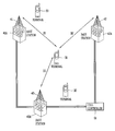
- FIG. 3 is a diagram showing a system for tracing a location of a mobile telecommunication terminal according to one embodiment of the present invention.
- This system includes mobile telecommunication terminals 31 , 32 , and 33 , base stations 41 , 42 , and 43 , and a cell controller 51 .
- the mobile telecommunication terminals transmit predetermined signals including discrimination information with a predetermined interval.
- the base stations calculate distance values from the mobile telecommunication terminals based on times for receiving the predetermined signals transmitted from the mobile telecommunication terminals.
- the base stations then transmit the distance values.
- the cell controller traces locations of the mobile telecommunication terminals using the distance values transmitted from the plurality of base stations.
- the base stations are provided with distance-calculation algorithm processing units 41 A, 42 A, and 43 A which calculate respective distances from the mobile telecommunication terminals 31 , 32 , and 33 .
- the respective mobile telecommunication terminals 31 , 32 , and 33 transmit predetermined signals including their discrimination information to the base stations 41 , 42 , and 43 with predetermined intervals.
- the base stations 41 , 42 , and 43 calculate distances from the mobile telecommunication terminal based on delayed times for receiving the predetermined signal from the terminal. At this time, in order to calculate the distances more accurately, a height of an antenna mounted at the base station has to be necessarily considered and the Pythagorean theorem is applied.
- the distance calculation algorithm processing units 41 A, 42 A, and 43 A mounted in the base stations 41 , 42 , and 43 include algorithms for calculating distances from the mobile telecommunication terminals and calculate accurate distance values through the algorithms.
- the algorithm maybe realized as a program which sequentially calculates distances between the mobile telecommunication terminals and the base stations according to the Pythagorean theorem. The distance calculation for which the Pythagorean theorem is used will be explained.
- FIG. 4 is a diagram explaining a distance calculation between one of the base stations and a mobile telecommunication terminal based on a delayed time of a predetermined signal transmitted from the mobile telecommunication terminal.
- the cell controller 51 combines distance information according to the distance values transmitted from the plurality of base stations and thereby traces locations of the mobile telecommunication terminals.
- the cell controller 51 sets/stores location information corresponding to each distance information in a table (not shown), and identifies the location information according to the distance information through the table, thereby determining regions which are the most similar to locations the mobile telecommunication terminals.
- FIG. 5 is a diagram illustrating a method for tracing a location of the terminal using a table mounted in the cell controller 51 in accordance with one embodiment of the present invention.
- This method includes dividing a region around or near one or more base stations into a plurality of areas, calculating distances between each base station and the mobile telecommunication terminal which maybe located in one of the divided areas and setting/storing the distance values and location information by the distance values in the table of the cell controller in advance.
- the method further includes receiving discrimination information transmitted from the mobile terminal and calculating distances between the mobile terminal and the respective base stations based on a delayed time for receiving the discrimination information.
- the calculated distance values are then transmitted to the cell controller and location information corresponding to the distance values between the mobile telecommunication terminal and the respective base stations transmitted from the respective base stations and discriminated through the table of the cell controller, thereby tracing locations of the mobile telecommunication terminals.
- location information corresponding to the distance values between the mobile telecommunication terminal and the respective base stations transmitted from the respective base stations and discriminated through the table of the cell controller, thereby tracing locations of the mobile telecommunication terminals.
- a region encompassing, near, or adjacent the three base stations is divided into areas A, B, C, . . . and I. It is noted that the divided region is not limited to areas A ⁇ I, as it ts possible to divide the regions into more or fewer areas. Also, even though three base stations are illustrated in drawings, those skilled in the art can appreciate that a different number of base stations maybe included. For example if there are more than three base stations, locations of the terminals located at expanded regions which extend outside the divided areas or which are located at detail areas except the center portion can be traced.
- the respective base stations calculate coordinate values (D1_A, D2_A, D3_A), (D1_B, D2_B, D3_B), (D1_C, D2_C, D3_C) . . . (D1_I, D2_I, D3_I) corresponding to distances between the terminals located at center portions of the divided areas A, B, C, . . . and I and the base stations. Then, the base stations transmit the values to the cell controller which connects the respective base stations. The cell controller previously sets/stores location information corresponding to the coordinate values in the basis table, and discriminates location information corresponding to the coordinate values in the table, to thereby tracing locations of the terminals.
- location tracing may be performed as follows.
- the coordinate values corresponding to distances between the base stations 41 , 42 , and 43 and the mobile telecommunication terminal 31 are calculated at the base stations 41 , 42 , and 43 and transmitted to the cell controller 51 .
- the cell controller 51 discriminates location information previously set and stored in the table mounted therein corresponding to the coordinate values D1, D2, and D3, thereby identifying that terminal 31 is located at the A region.
- the predetermined region is again divided into detail areas and corresponding coordinate values and location information corresponding to the coordinate values are previously set and stored in the table. Coordinate values corresponding to distances between terminals located at the portions except the center portions in the divided predetermined region and the base stations are calculated in the respective base stations 41 , 42 , and 43 . Subsequently, the cell controller 51 compares the coordinate values with those stored in the table, determines coordinate values of the basis table corresponding to the coordinate values, and selects location information corresponding to the coordinate values, thereby tracing a location of the mobile telecommunication terminal 31 .
- the location tracing method for the mobile telecommunication terminal 31 is suitable for a sophisticated location tracing of the mobile telecommunication terminal, since the divided region is re-divided into detail areas and thereby many coordinate values and location information corresponding to the coordinate values are previously set and stored in the basis table.
- the location tracing method involves the case where the mobile telecommunication terminal 31 is located at another portion except a center portion in one or more of the divided areas.
- the respective divided areas regions are re-divided into several regions not into detail areas, and corresponding coordinate values and location information corresponding to the coordinate values are previously set and stored in the basis table. Then, coordinate values corresponding to distances between the terminal located at another portion except the center portion in the predetermined area and the base stations are calculated in the base stations 41 , 42 , and 43 .
- the cell controller 51 compares the coordinate values with those stored in the table, discriminates coordinate values of the basis table which are the most similar to the coordinate values, and selects location information corresponding to the coordinate values, thereby tracing a location of the mobile telecommunication terminal 31 .
- coordinate values corresponding to distances between the base stations 41 , 42 , and 43 and the mobile telecommunication terminal 31 are calculated at the base stations 41 , 42 , and 43 and transmitted to the cell controller 51 .
- the cell controller 51 compares the coordinate values with those previously calculated and stored in the table in accordance with that the A region is re-divided into several regions, discriminates coordinate values of the basis table which are the most similar to the coordinate values, and selects location information corresponding to the coordinate values, thereby identifying that the mobile telecommunication terminal 31 is located at the predetermined region of the A region.
- the cell controller 51 determines and traces locations of the terminals wherever another mobile telecommunication terminals 3 , . . . 39 except the terminal 31 are located among said regions B, C, D . . . , and I.
- the cell controller 51 transmits region information of the traced mobile telecommunication terminal to the respective mobile telecommunication terminals 32 , 33 . . . , and 39 . Therefore, the respective terminals 32 , 33 , . . . and 39 identify their locations by receiving the region information.
- the location tracing system according to the present invention, distances between the terminals and the base stations are calculated by using reach delay time of predetermined signals transmitted from the terminals to the base stations and then the table of the cell controller which previously sets and stores location information corresponding to the calculated distances is identified, thereby tracing locations of the mobile telecommunication terminals. Accordingly, since the location tracing system according to the present invention does not need the GPS receiver which had to be necessarily mounted in the conventional terminal at the time of using the GPS, a system realization is facilitated. Also, since the related resource can be used as it is, a cost is reduced.
- the location tracing system according to the present invention has a greatly reduced error range.
Abstract
Description
- 1. Field of the Invention
- The present invention relates to a mobile telecommunication terminal, and more particularly to a system and method for tracing a location of the terminal in a service area.
- 2. Background of the Related Art
- One conventional system for tracing the location of a mobile telecommunication terminal involves mounting a global positioning system (GPS) receiver in the terminal and then determing location by analyzing a signal received from a low-earth-orbit satellite. A second conventional system traces the location of a terminal using a network of a wireless telecommunication system. These methods will now be explained.
- FIG. 1 shows the first conventional system, which traces the location of a mobile telecommunication terminal by analyzing a signal from a low-earth-orbit satellite. This system includes a
satellite receiving unit 10 which receives satellite signals transmitted from a plurality of universal GPS satellites (1˜N). Location information included in the received signals and time deviations of the received signals, are then used to trace the location of the terminal. In this system, the GPS satellites (1˜N) and thesatellite receiving unit 10 require a substantial amount of locking time at first. Also, sending/receiving of the satellite signal is disturbed by adjacent architectures and a receiving sensitivity of the satellite signal is very weak. Accordingly, a location of the mobile telecommunication terminal is inaccurately recognized and much cost is required. - FIG. 2 shows the second conventional system, which traces the location of the mobile telecommunication terminal using a network of a wireless telecommunication system. This sytem includes a plurality of base stations 22-1, 22-2, . . . 22-n which receive a predetermined signal transmitted from the
mobile telecommunication terminal 21. Alocation calculation unit 23 then calculates a location of the terminal using location information according to the predetermined signal from the plurality of base stations and reception time deviation between the received signals. The calculated result is provided to themobile telecommunication terminal 21. - The second conventional system described above performs location tracing based on a distance difference between the
mobile telecommunication terminal 21 and the base stations 22-1, 22-2, . . . 22-n. As a result, a base station located far from the terminal has difficulty in receiving a signal necessary to calculate a location, since the base station has a weak receiving sensitivity for the signal transmitted from the terminal. In order to solve this problem, it has been proposed to increase a strength for transmittance force of the corresponding terminal. However, it has been shown that a terminal having an increased transmittance force does not easily recognize the signal transmitted from a base station located far from the terminal. That is, in the second conventional system for tracing a location of the mobile telecommunication terminal using a network of a wireless telecommunication system, even if the GPS receiver does not have to be mounted in the mobile telecommunication terminal, an error range for a location of the terminal is substantial. - An object of the invention is to solve at least the above problems and/or disadvantages and to provide at least the advantages described hereinafter.
- An object of the present invention is to provide a system and method for tracing the location of a mobile telecommunication terminal by calculating distances between the terminal and base stations based on delayed time for receiving a predetermined signal transmitted from the terminal to the base stations.
- It is another object of the present invention to provide the base stations with distance calculation algorithm processing units which calculate distances between the base stations and the mobile telecommunication terminal.
- To achieve these and other objects and advantages, the present invention provides a location tracing system for a mobile telecommunication terminal comprising: mobile telecommunication terminals for transmitting predetermined signals including their discrimination information with predetermined intervals; a plurality of base stations for calculating distances from the mobile telecommunication terminals on the basis of reception time for the predetermined signals transmitted from the mobile telecommunication terminals and then transmitting the distance values; and a cell controller for tracing locations of the mobile telecommunication terminals by using the distance values transmitted from the plurality of base stations. Herein, the cell controller sets/stores location information corresponding to the respective distance values in a table in advance and certifies the location information by the table, thereby determining regions which are the most similar to locations of the mobile telecommunication terminals.
- The present invention is also a method for tracing locations of the mobile telecommunication terminals comprising: dividing a region around the base stations, calculating distances between mobile telecommunication terminals located at the divided regions and each base station, and setting/storing the distance values and location information by the distance values in a table of a cell controller in advance; receiving discrimination information transmitted from the mobile telecommunication terminals and calculating distances between the mobile telecommunication terminals and the respective base stations on the basis of delayed time for receiving the discrimination information; transmitting the calculated distance values to the cell controller; and discriminating location information corresponding to the distance values between the mobile telecommunication terminals and the respective base stations transmitted from the respective base stations by the table of the cell controller, thereby tracing locations of the mobile telecommunication terminals.
- FIG. 1 is a diagram showing a construction of a first system for tracing a location of a mobile telecommunication terminal by analyzing a satellite signal according to a conventional low earth orbit satellite;
- FIG. 2 is a diagram showing a construction of a second system for tracing a location of a mobile telecommunication terminal by using a network of a conventional wireless telecommunication system;
- FIG. 3 is a diagram showing a location tracing system for a mobile telecommunication terminal according to one embodiment of the present invention;
- FIG. 4 is a diagram indicating how a distance calculation maybe perfomed between a base station and a mobile telecommunication terminal based on a delayed time of a predetermined signal transmitted from the mobile telecommunication terminal; and
- FIG. 5 is a diagram explaining a location tracing method for a mobile telecommunication terminal according to an embodiment of the present invention.
- FIG. 3 is a diagram showing a system for tracing a location of a mobile telecommunication terminal according to one embodiment of the present invention. This system includes
mobile telecommunication terminals base stations cell controller 51. The mobile telecommunication terminals transmit predetermined signals including discrimination information with a predetermined interval. The base stations calculate distance values from the mobile telecommunication terminals based on times for receiving the predetermined signals transmitted from the mobile telecommunication terminals. The base stations then transmit the distance values. The cell controller traces locations of the mobile telecommunication terminals using the distance values transmitted from the plurality of base stations. In this system, the base stations are provided with distance-calculationalgorithm processing units mobile telecommunication terminals - Operations of the location tracing system of the present invention will now be explained. First, the respective
mobile telecommunication terminals base stations - Then, for each
terminal base stations - The distance calculation
algorithm processing units base stations - FIG. 4 is a diagram explaining a distance calculation between one of the base stations and a mobile telecommunication terminal based on a delayed time of a predetermined signal transmitted from the mobile telecommunication terminal.
- As shown, the distance L between the base station antenna and the mobile telecommunication terminal is obtained by multiplying the height of the antenna h and reach delay time T of the predetermined signals transmitted from the terminal to the base station. Then, the distance D between the terminal and the base station is obtained by using the Pythagorean theorem, where D={square root}{square root over (L 2−h2)}.
- Subsequently, the
cell controller 51 combines distance information according to the distance values transmitted from the plurality of base stations and thereby traces locations of the mobile telecommunication terminals. Herein, thecell controller 51 sets/stores location information corresponding to each distance information in a table (not shown), and identifies the location information according to the distance information through the table, thereby determining regions which are the most similar to locations the mobile telecommunication terminals. - FIG. 5 is a diagram illustrating a method for tracing a location of the terminal using a table mounted in the
cell controller 51 in accordance with one embodiment of the present invention. This method includes dividing a region around or near one or more base stations into a plurality of areas, calculating distances between each base station and the mobile telecommunication terminal which maybe located in one of the divided areas and setting/storing the distance values and location information by the distance values in the table of the cell controller in advance. The method further includes receiving discrimination information transmitted from the mobile terminal and calculating distances between the mobile terminal and the respective base stations based on a delayed time for receiving the discrimination information. - The calculated distance values are then transmitted to the cell controller and location information corresponding to the distance values between the mobile telecommunication terminal and the respective base stations transmitted from the respective base stations and discriminated through the table of the cell controller, thereby tracing locations of the mobile telecommunication terminals. A non-limiting example of this method follows.
- In order to trace locations of a mobile telecommunication terminal using three base stations, a region encompassing, near, or adjacent the three base stations is divided into areas A, B, C, . . . and I. It is noted that the divided region is not limited to areas A˜I, as it ts possible to divide the regions into more or fewer areas. Also, even though three base stations are illustrated in drawings, those skilled in the art can appreciate that a different number of base stations maybe included. For example if there are more than three base stations, locations of the terminals located at expanded regions which extend outside the divided areas or which are located at detail areas except the center portion can be traced.
- The respective base stations calculate coordinate values (D1_A, D2_A, D3_A), (D1_B, D2_B, D3_B), (D1_C, D2_C, D3_C) . . . (D1_I, D2_I, D3_I) corresponding to distances between the terminals located at center portions of the divided areas A, B, C, . . . and I and the base stations. Then, the base stations transmit the values to the cell controller which connects the respective base stations. The cell controller previously sets/stores location information corresponding to the coordinate values in the basis table, and discriminates location information corresponding to the coordinate values in the table, to thereby tracing locations of the terminals.
- For example in case that one
mobile telecommunication terminal 31 is located at a center portion of the A region, location tracing may be performed as follows. - First, the coordinate values corresponding to distances between the
base stations mobile telecommunication terminal 31 are calculated at thebase stations cell controller 51. Then, thecell controller 51 discriminates location information previously set and stored in the table mounted therein corresponding to the coordinate values D1, D2, and D3, thereby identifying that terminal 31 is located at the A region. - In the case where terminals are located at portions except the center portions in the divided areas, the predetermined region is again divided into detail areas and corresponding coordinate values and location information corresponding to the coordinate values are previously set and stored in the table. Coordinate values corresponding to distances between terminals located at the portions except the center portions in the divided predetermined region and the base stations are calculated in the
respective base stations cell controller 51 compares the coordinate values with those stored in the table, determines coordinate values of the basis table corresponding to the coordinate values, and selects location information corresponding to the coordinate values, thereby tracing a location of themobile telecommunication terminal 31. - The location tracing method for the
mobile telecommunication terminal 31 is suitable for a sophisticated location tracing of the mobile telecommunication terminal, since the divided region is re-divided into detail areas and thereby many coordinate values and location information corresponding to the coordinate values are previously set and stored in the basis table. - As another example of the location tracing method involves the case where the
mobile telecommunication terminal 31 is located at another portion except a center portion in one or more of the divided areas. Here, the respective divided areas regions are re-divided into several regions not into detail areas, and corresponding coordinate values and location information corresponding to the coordinate values are previously set and stored in the basis table. Then, coordinate values corresponding to distances between the terminal located at another portion except the center portion in the predetermined area and the base stations are calculated in thebase stations cell controller 51 compares the coordinate values with those stored in the table, discriminates coordinate values of the basis table which are the most similar to the coordinate values, and selects location information corresponding to the coordinate values, thereby tracing a location of themobile telecommunication terminal 31. - The case where one
mobile telecommunication terminal 31 is located at another portions except a center portion in the A area will now be explained. - First, coordinate values corresponding to distances between the
base stations mobile telecommunication terminal 31 are calculated at thebase stations cell controller 51. Thecell controller 51 compares the coordinate values with those previously calculated and stored in the table in accordance with that the A region is re-divided into several regions, discriminates coordinate values of the basis table which are the most similar to the coordinate values, and selects location information corresponding to the coordinate values, thereby identifying that themobile telecommunication terminal 31 is located at the predetermined region of the A region. - Accordingly, the
cell controller 51 determines and traces locations of the terminals wherever another mobile telecommunication terminals 3, . . . 39 except the terminal 31 are located among said regions B, C, D . . . , and I. - Subsequently, the
cell controller 51 transmits region information of the traced mobile telecommunication terminal to the respectivemobile telecommunication terminals respective terminals - As aforementioned, in the location tracing system according to the present invention, distances between the terminals and the base stations are calculated by using reach delay time of predetermined signals transmitted from the terminals to the base stations and then the table of the cell controller which previously sets and stores location information corresponding to the calculated distances is identified, thereby tracing locations of the mobile telecommunication terminals. Accordingly, since the location tracing system according to the present invention does not need the GPS receiver which had to be necessarily mounted in the conventional terminal at the time of using the GPS, a system realization is facilitated. Also, since the related resource can be used as it is, a cost is reduced.
- Besides, when compared with the conventional location tracing system for tracing a location of the terminal by using a network of a wireless communication system, the location tracing system according to the present invention has a greatly reduced error range.
- The foregoing embodiments and advantages are merely exemplary and are not to be construed as limiting the present invention. The present teaching can be readily applied to other types of apparatuses. The description of the present invention is intended to be illustrative, and not to limit the scope of the claims. Many alternatives, modifications, and variations will be apparent to those skilled in the art. In the claims, means-plus-function clauses are intended to cover the structures described herein as performing the recited function and not only structural equivalents but also equivalent structures.
Claims (20)
Applications Claiming Priority (2)
| Application Number | Priority Date | Filing Date | Title |
|---|---|---|---|
| KR10-2002-0016801A KR100469416B1 (en) | 2002-03-27 | 2002-03-27 | Location tracing apparatus and method for mobile terminal |
| KR16801/2002 | 2002-03-27 |
Publications (2)
| Publication Number | Publication Date |
|---|---|
| US20030190920A1 true US20030190920A1 (en) | 2003-10-09 |
| US7398092B2 US7398092B2 (en) | 2008-07-08 |
Family
ID=28450085
Family Applications (1)
| Application Number | Title | Priority Date | Filing Date |
|---|---|---|---|
| US10/394,053 Expired - Fee Related US7398092B2 (en) | 2002-03-27 | 2003-03-24 | Location tracing system for mobile telecommunication terminal and method thereof |
Country Status (3)
| Country | Link |
|---|---|
| US (1) | US7398092B2 (en) |
| KR (1) | KR100469416B1 (en) |
| CN (1) | CN1247039C (en) |
Cited By (12)
| Publication number | Priority date | Publication date | Assignee | Title |
|---|---|---|---|---|
| US20050014512A1 (en) * | 2003-07-16 | 2005-01-20 | Gerecht Douglas A. | Assistance techniques for subscriber units having positioning capabilities |
| US20050215269A1 (en) * | 2004-02-17 | 2005-09-29 | Jadi Inc. | Navigation system |
| US20050288025A1 (en) * | 2004-06-25 | 2005-12-29 | Hitachi Communication Technologies, Ltd. | Radio communication system and base station |
| US20060080004A1 (en) * | 2004-04-29 | 2006-04-13 | Jadi Inc. | Self-leveling laser horizon for navigation guidance |
| GB2441373A (en) * | 2006-09-04 | 2008-03-05 | Siemens Ag | A method of determining location in a mobile device |
| US20080234930A1 (en) * | 2007-03-21 | 2008-09-25 | Jadi Inc. | Navigation unit and base station |
| US20080262669A1 (en) * | 2006-09-22 | 2008-10-23 | Jadi, Inc. | Autonomous vehicle controller |
| US20090088167A1 (en) * | 2005-12-22 | 2009-04-02 | Wichorus | Method and apparatus to estimate relative base station and subscriber terminal locations and using it to increase frequency reuse |
| WO2010149796A1 (en) | 2009-06-26 | 2010-12-29 | Masat B.V. | Method and system for determining the location of a moving sensor node |
| US20110230206A1 (en) * | 2006-08-18 | 2011-09-22 | Andrew, Llc | System and method for single sensor geolocation |
| CN102435979A (en) * | 2011-09-08 | 2012-05-02 | 浙江工商大学 | Method for improving wireless positioning precision of stacker |
| US20120165040A1 (en) * | 2010-12-23 | 2012-06-28 | Electronics And Telecommunications Research Institute | Method for locating wireless nodes using difference triangulation |
Families Citing this family (6)
| Publication number | Priority date | Publication date | Assignee | Title |
|---|---|---|---|---|
| JP4608001B2 (en) * | 2006-10-02 | 2011-01-05 | パナソニック株式会社 | Mobile station apparatus and sequence allocation method |
| JP5052244B2 (en) * | 2007-07-20 | 2012-10-17 | 株式会社エヌ・ティ・ティ・ドコモ | Wireless communication system |
| GB2466296A (en) * | 2008-12-22 | 2010-06-23 | Vodafone Plc | Terminal Positioning Technique |
| CN103686927A (en) * | 2012-09-04 | 2014-03-26 | 阿尔卡特朗讯 | Method and device for judging whether to terminate communication between mobile terminal and base station |
| CN104010362B (en) * | 2013-02-22 | 2018-01-19 | 华为技术有限公司 | The method, apparatus and location equipment of positioning terminal position |
| CN105234746A (en) * | 2015-11-25 | 2016-01-13 | 苏州多荣自动化科技有限公司 | Online tool wear monitoring system and detection method thereof |
Citations (6)
| Publication number | Priority date | Publication date | Assignee | Title |
|---|---|---|---|---|
| US20020009974A1 (en) * | 2000-07-17 | 2002-01-24 | Mikio Kuwahara | Wireless communication base station transmission timing offset correction system |
| US20020086682A1 (en) * | 1999-05-05 | 2002-07-04 | Siamak Naghian | Method for positioning a mobile station |
| US20020132628A1 (en) * | 1999-10-29 | 2002-09-19 | Norihisa Matsumoto | Method for control hand-off of CDMA system, base station used therefor, and base station controller |
| US6526039B1 (en) * | 1998-02-12 | 2003-02-25 | Telefonaktiebolaget Lm Ericsson | Method and system for facilitating timing of base stations in an asynchronous CDMA mobile communications system |
| US20030114169A1 (en) * | 2001-12-14 | 2003-06-19 | Hitachi, Ltd. | Method and system for detecting the position of mobile station |
| US20040033818A1 (en) * | 2000-11-30 | 2004-02-19 | Hiroshi Nakamura | Mobile communication device |
Family Cites Families (7)
| Publication number | Priority date | Publication date | Assignee | Title |
|---|---|---|---|---|
| JPH10257545A (en) | 1997-03-11 | 1998-09-25 | Sony Corp | Communication system and mobile communication terminal equipment |
| US6011974A (en) * | 1997-09-23 | 2000-01-04 | Telefonaktiebolaget L M Ericsson (Publ) | Method and system for determining position of a cellular mobile terminal |
| KR19990039959A (en) * | 1997-11-15 | 1999-06-05 | 이재훈 | Location tracking method of mobile communication terminal |
| KR100290926B1 (en) * | 1997-12-27 | 2001-07-12 | 서평원 | Method of tracing location of mobile subscriber |
| US6198935B1 (en) * | 1998-11-17 | 2001-03-06 | Ericsson Inc. | System and method for time of arrival positioning measurements based upon network characteristics |
| CA2307475A1 (en) * | 2000-05-03 | 2001-11-03 | Universite Du Quebec A Montreal | Ceruloplasmin and uses thereof in neurodegenerative related conditions |
| KR100834616B1 (en) * | 2002-02-27 | 2008-06-02 | 삼성전자주식회사 | Method for determining ms location without gps in mobile communication system |
-
2002
- 2002-03-27 KR KR10-2002-0016801A patent/KR100469416B1/en not_active IP Right Cessation
-
2003
- 2003-03-24 US US10/394,053 patent/US7398092B2/en not_active Expired - Fee Related
- 2003-03-27 CN CNB03108320XA patent/CN1247039C/en not_active Expired - Fee Related
Patent Citations (8)
| Publication number | Priority date | Publication date | Assignee | Title |
|---|---|---|---|---|
| US6526039B1 (en) * | 1998-02-12 | 2003-02-25 | Telefonaktiebolaget Lm Ericsson | Method and system for facilitating timing of base stations in an asynchronous CDMA mobile communications system |
| US20020086682A1 (en) * | 1999-05-05 | 2002-07-04 | Siamak Naghian | Method for positioning a mobile station |
| US20020132628A1 (en) * | 1999-10-29 | 2002-09-19 | Norihisa Matsumoto | Method for control hand-off of CDMA system, base station used therefor, and base station controller |
| US6980805B2 (en) * | 1999-10-29 | 2005-12-27 | Fujitsu Limited | Method for control hand-off of CDMA system, base station used therefor, and base station controller |
| US20020009974A1 (en) * | 2000-07-17 | 2002-01-24 | Mikio Kuwahara | Wireless communication base station transmission timing offset correction system |
| US6704547B2 (en) * | 2000-07-17 | 2004-03-09 | Hitachi, Ltd. | Wireless communication base station transmission timing offset correction system |
| US20040033818A1 (en) * | 2000-11-30 | 2004-02-19 | Hiroshi Nakamura | Mobile communication device |
| US20030114169A1 (en) * | 2001-12-14 | 2003-06-19 | Hitachi, Ltd. | Method and system for detecting the position of mobile station |
Cited By (29)
| Publication number | Priority date | Publication date | Assignee | Title |
|---|---|---|---|---|
| US20050014512A1 (en) * | 2003-07-16 | 2005-01-20 | Gerecht Douglas A. | Assistance techniques for subscriber units having positioning capabilities |
| US7047020B2 (en) * | 2003-07-16 | 2006-05-16 | Qualcomm Inc. | Assistance techniques for subscriber units having positioning capabilities |
| US7403783B2 (en) | 2004-02-17 | 2008-07-22 | Jadi, Inc. | Navigation system |
| US20050215269A1 (en) * | 2004-02-17 | 2005-09-29 | Jadi Inc. | Navigation system |
| US7983694B2 (en) | 2004-02-17 | 2011-07-19 | Nav-Track, Inc. | Target and base station for a navigation system |
| US8010133B2 (en) | 2004-02-17 | 2011-08-30 | Nav-Track, Inc. | Navigation system |
| US20080103696A1 (en) * | 2004-02-17 | 2008-05-01 | Jadi Inc. | Navigation system |
| US20080167051A1 (en) * | 2004-02-17 | 2008-07-10 | Jadi Inc. | Navigation system |
| US20060080004A1 (en) * | 2004-04-29 | 2006-04-13 | Jadi Inc. | Self-leveling laser horizon for navigation guidance |
| US7908041B2 (en) | 2004-04-29 | 2011-03-15 | Munro & Associates, Inc. | Self-leveling laser horizon for navigation guidance |
| US20080182612A1 (en) * | 2004-06-25 | 2008-07-31 | Hitachi Communication Technologies, Ltd. | Radio Communication System and Base Station |
| US8073381B2 (en) | 2004-06-25 | 2011-12-06 | Hitachi, Ltd. | Radio communication system and base station |
| US7996033B2 (en) | 2004-06-25 | 2011-08-09 | Hitachi Communication Technologies, Ltd. | Radio communication system and base station |
| US20090023382A1 (en) * | 2004-06-25 | 2009-01-22 | Hitachi Communication Technologies, Ltd. | Radio Communication System and Base Station |
| US20050288025A1 (en) * | 2004-06-25 | 2005-12-29 | Hitachi Communication Technologies, Ltd. | Radio communication system and base station |
| US7738875B2 (en) * | 2005-12-22 | 2010-06-15 | Wichorus Inc | Method and apparatus to estimate relative base station and subscriber terminal locations and using it to increase frequency reuse |
| US8224340B2 (en) * | 2005-12-22 | 2012-07-17 | Wichorus, Inc. | Method and apparatus to estimate relative base station and subscriber terminal locations and using it to increase frequency reuse |
| US20100216463A1 (en) * | 2005-12-22 | 2010-08-26 | Wichorus Inc. | Method and apparatus to estimate relative base station and subscriber terminal locations and using it to increase frequency reuse |
| US20090088167A1 (en) * | 2005-12-22 | 2009-04-02 | Wichorus | Method and apparatus to estimate relative base station and subscriber terminal locations and using it to increase frequency reuse |
| US20130016660A1 (en) * | 2005-12-22 | 2013-01-17 | Wichorus, Inc. | Method and apparatus to estimate relative base station and subscriber terminal locations and using it to increase frequency reuse |
| US20120220304A1 (en) * | 2005-12-22 | 2012-08-30 | Tellabs Operations, Inc. | Method and Apparatus To Estimate Relative Base Station and Subscriber Terminal Locations and Using It To Increase Frequency Reuse |
| US20110230206A1 (en) * | 2006-08-18 | 2011-09-22 | Andrew, Llc | System and method for single sensor geolocation |
| GB2441373A (en) * | 2006-09-04 | 2008-03-05 | Siemens Ag | A method of determining location in a mobile device |
| US20080262669A1 (en) * | 2006-09-22 | 2008-10-23 | Jadi, Inc. | Autonomous vehicle controller |
| US8214147B2 (en) | 2007-03-21 | 2012-07-03 | Nav-Track, Inc. | Navigation unit and base station |
| US20080234930A1 (en) * | 2007-03-21 | 2008-09-25 | Jadi Inc. | Navigation unit and base station |
| WO2010149796A1 (en) | 2009-06-26 | 2010-12-29 | Masat B.V. | Method and system for determining the location of a moving sensor node |
| US20120165040A1 (en) * | 2010-12-23 | 2012-06-28 | Electronics And Telecommunications Research Institute | Method for locating wireless nodes using difference triangulation |
| CN102435979A (en) * | 2011-09-08 | 2012-05-02 | 浙江工商大学 | Method for improving wireless positioning precision of stacker |
Also Published As
| Publication number | Publication date |
|---|---|
| CN1447617A (en) | 2003-10-08 |
| US7398092B2 (en) | 2008-07-08 |
| CN1247039C (en) | 2006-03-22 |
| KR100469416B1 (en) | 2005-02-02 |
| KR20030077849A (en) | 2003-10-04 |
Similar Documents
| Publication | Publication Date | Title |
|---|---|---|
| US7398092B2 (en) | Location tracing system for mobile telecommunication terminal and method thereof | |
| US7383051B2 (en) | Estimating the location of a mobile unit based on the elimination of improbable locations | |
| US7725111B2 (en) | Location determination using RF fingerprinting | |
| US7408509B2 (en) | Direction finding method and system using probabilistic mapping | |
| US8106817B2 (en) | Positioning system and positioning method | |
| EP0982964B1 (en) | Pattern recognition-based geolocation | |
| US8013785B2 (en) | Positioning system and positioning method | |
| US7345630B2 (en) | System and method for position detection of a terminal in a network | |
| US7474646B2 (en) | Wireless communication system, node position calculation method and node | |
| EP1496370A1 (en) | Position Acquisition | |
| US20090047975A1 (en) | Method for Tracking Location of a Mobile Unit | |
| CN105430744B (en) | Positioning method and positioning system | |
| CN102440043A (en) | Wireless communication network | |
| WO2018121439A1 (en) | Method and apparatus for determining direct path | |
| CN109587631B (en) | Indoor positioning method and device | |
| JPH11178066A (en) | Navigation system and location detection method thereof | |
| US20050079876A1 (en) | Method of location using signals of unknown origin | |
| CN207158534U (en) | A kind of floor detection prompt system and mobile terminal | |
| JPH06224812A (en) | Reception level measuring circuit | |
| JP2912357B1 (en) | Mobile radio systems | |
| JP2002026791A (en) | Data communication terminal | |
| WO1999065251A2 (en) | Apparatus and method for detecting calling location of radio signal using short pulse | |
| JP2016090311A (en) | Positioning device | |
| CN113759307A (en) | Method and device for positioning wireless signal | |
| CN102043140A (en) | Mobile phone positioning and ranging system and method |
Legal Events
| Date | Code | Title | Description |
|---|---|---|---|
| AS | Assignment |
Owner name: LG ELECTRONICS INC., KOREA, REPUBLIC OF Free format text: ASSIGNMENT OF ASSIGNORS INTEREST;ASSIGNOR:AN, KWANG-JIN;REEL/FRAME:013905/0353 Effective date: 20030307 |
|
| FEPP | Fee payment procedure |
Free format text: PAYOR NUMBER ASSIGNED (ORIGINAL EVENT CODE: ASPN); ENTITY STATUS OF PATENT OWNER: LARGE ENTITY |
|
| STCF | Information on status: patent grant |
Free format text: PATENTED CASE |
|
| FEPP | Fee payment procedure |
Free format text: PAYOR NUMBER ASSIGNED (ORIGINAL EVENT CODE: ASPN); ENTITY STATUS OF PATENT OWNER: LARGE ENTITY Free format text: PAYER NUMBER DE-ASSIGNED (ORIGINAL EVENT CODE: RMPN); ENTITY STATUS OF PATENT OWNER: LARGE ENTITY |
|
| FPAY | Fee payment |
Year of fee payment: 4 |
|
| FPAY | Fee payment |
Year of fee payment: 8 |
|
| FEPP | Fee payment procedure |
Free format text: MAINTENANCE FEE REMINDER MAILED (ORIGINAL EVENT CODE: REM.); ENTITY STATUS OF PATENT OWNER: LARGE ENTITY |
|
| LAPS | Lapse for failure to pay maintenance fees |
Free format text: PATENT EXPIRED FOR FAILURE TO PAY MAINTENANCE FEES (ORIGINAL EVENT CODE: EXP.); ENTITY STATUS OF PATENT OWNER: LARGE ENTITY |
|
| STCH | Information on status: patent discontinuation |
Free format text: PATENT EXPIRED DUE TO NONPAYMENT OF MAINTENANCE FEES UNDER 37 CFR 1.362 |
|
| FP | Lapsed due to failure to pay maintenance fee |
Effective date: 20200708 |