US20040002347A1 - Transmitter location for ultra-wideband, transmitted-reference CDMA communication system - Google Patents
Transmitter location for ultra-wideband, transmitted-reference CDMA communication system Download PDFInfo
- Publication number
- US20040002347A1 US20040002347A1 US10/609,891 US60989103A US2004002347A1 US 20040002347 A1 US20040002347 A1 US 20040002347A1 US 60989103 A US60989103 A US 60989103A US 2004002347 A1 US2004002347 A1 US 2004002347A1
- Authority
- US
- United States
- Prior art keywords
- signals
- location
- uwb
- interest
- area
- Prior art date
- Legal status (The legal status is an assumption and is not a legal conclusion. Google has not performed a legal analysis and makes no representation as to the accuracy of the status listed.)
- Granted
Links
- 238000004891 communication Methods 0.000 title description 22
- 238000000034 method Methods 0.000 claims abstract description 44
- 230000005540 biological transmission Effects 0.000 claims description 62
- 238000001228 spectrum Methods 0.000 claims description 14
- 238000004364 calculation method Methods 0.000 claims 1
- 239000000523 sample Substances 0.000 description 19
- 239000011159 matrix material Substances 0.000 description 15
- 239000013598 vector Substances 0.000 description 15
- 230000001934 delay Effects 0.000 description 10
- 238000005259 measurement Methods 0.000 description 9
- 238000010586 diagram Methods 0.000 description 8
- 230000000694 effects Effects 0.000 description 7
- 238000001514 detection method Methods 0.000 description 6
- 238000009826 distribution Methods 0.000 description 6
- 230000001360 synchronised effect Effects 0.000 description 6
- 230000003111 delayed effect Effects 0.000 description 4
- 238000005516 engineering process Methods 0.000 description 4
- 230000008569 process Effects 0.000 description 4
- 238000007792 addition Methods 0.000 description 3
- 238000012544 monitoring process Methods 0.000 description 3
- 101100458289 Drosophila melanogaster msps gene Proteins 0.000 description 2
- 230000000875 corresponding effect Effects 0.000 description 2
- 238000013461 design Methods 0.000 description 2
- 238000011161 development Methods 0.000 description 2
- 230000018109 developmental process Effects 0.000 description 2
- 230000007613 environmental effect Effects 0.000 description 2
- 238000009434 installation Methods 0.000 description 2
- 230000010354 integration Effects 0.000 description 2
- 238000005457 optimization Methods 0.000 description 2
- 230000005855 radiation Effects 0.000 description 2
- 230000004044 response Effects 0.000 description 2
- 238000005070 sampling Methods 0.000 description 2
- 238000012935 Averaging Methods 0.000 description 1
- 238000007476 Maximum Likelihood Methods 0.000 description 1
- 229910000831 Steel Inorganic materials 0.000 description 1
- 230000002411 adverse Effects 0.000 description 1
- 230000032683 aging Effects 0.000 description 1
- 238000013459 approach Methods 0.000 description 1
- 230000000747 cardiac effect Effects 0.000 description 1
- 239000000969 carrier Substances 0.000 description 1
- 230000008859 change Effects 0.000 description 1
- 239000002131 composite material Substances 0.000 description 1
- 239000012141 concentrate Substances 0.000 description 1
- 238000010276 construction Methods 0.000 description 1
- 230000002596 correlated effect Effects 0.000 description 1
- 239000010432 diamond Substances 0.000 description 1
- 238000005562 fading Methods 0.000 description 1
- 238000009432 framing Methods 0.000 description 1
- 230000001939 inductive effect Effects 0.000 description 1
- 238000012423 maintenance Methods 0.000 description 1
- 238000004519 manufacturing process Methods 0.000 description 1
- 239000003550 marker Substances 0.000 description 1
- 239000000463 material Substances 0.000 description 1
- 238000012986 modification Methods 0.000 description 1
- 230000004048 modification Effects 0.000 description 1
- 238000005192 partition Methods 0.000 description 1
- 238000012545 processing Methods 0.000 description 1
- 230000009467 reduction Effects 0.000 description 1
- 230000008439 repair process Effects 0.000 description 1
- 238000011160 research Methods 0.000 description 1
- 230000000717 retained effect Effects 0.000 description 1
- 238000000926 separation method Methods 0.000 description 1
- 230000008054 signal transmission Effects 0.000 description 1
- 230000011664 signaling Effects 0.000 description 1
- 238000004088 simulation Methods 0.000 description 1
- 238000010561 standard procedure Methods 0.000 description 1
- 239000010959 steel Substances 0.000 description 1
- 238000003860 storage Methods 0.000 description 1
- 238000002604 ultrasonography Methods 0.000 description 1
Images


Classifications
-
- H—ELECTRICITY
- H04—ELECTRIC COMMUNICATION TECHNIQUE
- H04B—TRANSMISSION
- H04B1/00—Details of transmission systems, not covered by a single one of groups H04B3/00 - H04B13/00; Details of transmission systems not characterised by the medium used for transmission
- H04B1/69—Spread spectrum techniques
- H04B1/7163—Spread spectrum techniques using impulse radio
-
- G—PHYSICS
- G01—MEASURING; TESTING
- G01S—RADIO DIRECTION-FINDING; RADIO NAVIGATION; DETERMINING DISTANCE OR VELOCITY BY USE OF RADIO WAVES; LOCATING OR PRESENCE-DETECTING BY USE OF THE REFLECTION OR RERADIATION OF RADIO WAVES; ANALOGOUS ARRANGEMENTS USING OTHER WAVES
- G01S5/00—Position-fixing by co-ordinating two or more direction or position line determinations; Position-fixing by co-ordinating two or more distance determinations
- G01S5/02—Position-fixing by co-ordinating two or more direction or position line determinations; Position-fixing by co-ordinating two or more distance determinations using radio waves
- G01S5/06—Position of source determined by co-ordinating a plurality of position lines defined by path-difference measurements
Definitions
- Various embodiments of the present invention relate to the use of ultra-wideband (UWB) radio communication systems.
- the various embodiments pertain to a transmitted-reference, delayed hopped (TR/DH) UWB radio communications system for use in an asset tracking system.
- TR/DH delayed hopped
- Wireless, narrowband or conventional spread-spectrum communications systems have been proposed for tracking objects within an area of interest. Some of these systems are bi-directional and operate via polling. Others are one-way and transmit based on movement of an asset tag (a small transmitter attached to an item to be tracked) or according to some predetermined schedule that is independent of environmental conditions. Still other systems track objects based on time-difference-of-arrival (TDOA) information or by using crude field-strength measurements. In addition to their tracking function, such systems have been used to provide discrete status information which, for example, may indicate whether a device is powered on.
- TDOA time-difference-of-arrival
- narrowband and spread-spectrum systems have proven useful, they are not without drawbacks. For example, the performance of such systems may be adversely affected by interference from strong local RF emitters. The opposite is also true; i.e., because their transmitted energy is concentrated in a relatively limited spectrum, narrowband and conventional spread-spectrum systems may interfere with sensitive communications equipment located within or even external to the operating region.
- Narrowband or spread-spectrum systems have also demonstrated poor performance in urban areas, or areas where there is a high concentration of electromagnetic interference. For example, such transmissions are often unable to penetrate building components (e.g., walls, steel structures, elevator shafts, etc.), thereby making their use impracticable in many cases.
- narrowband systems often require large power margins in order to combat significant frequency-selective fading, which is associated with indoor RF transmissions.
- Time-Difference-of-Arrival is one method that is used to estimate the point of origin of a transmission observed at several receivers.
- each receiver accesses a global clock or timebase so that local Time-of-Arrival (TOA) estimates made at the individual receivers can be compared.
- TOA Time-of-Arrival
- An observed difference in TOA at two receivers of known location defines a hyperbola on the plane containing the two receivers and the transmitter. Because the location of the application described here is indoors, the range of values taken by the height of the transmitter off the floor is limited. This being the case, one can approximate the problem by treating all receivers and all asset tags as though they lie in the same plane.
- the secondary wired network is also used to distribute the global timebase to all the receivers in the system, which uses bandwidth on the wired network as well as extra hardware at the receivers.
- the use of extra bandwidth on the secondary wired network is a drawback, because it contributes substantially to the system cost.
- U.S. Pat. No. 5,119,104 notably describes a conventional spread-spectrum system which operates by distributing a clock to a plurality of receivers in a tracking environment, and which then uses that clock to gate a time-of-arrival (TOA) count within each of a plurality of receivers.
- TOA time-of-arrival
- the TOA count is used to estimate the RF propagation distance between a transmitting tag and the receiver.
- the system clock typically should have very little skew between the receivers because each ins of clock skew could introduce as much as 1 foot of ranging error in the system.
- Clock skew is easily introduced when the system clock is distributed with a cable. Therefore, cable lengths are carefully measured or controlled during installation of the system, and calibrations are made in the system to account for the different clock skews introduced by the cabling. This increases system cost and complicates installation as well as maintenance and repair of the system.
- a method for determining a location of an object within an area of interest includes transmitting wireless signals from a plurality of objects to at least three receivers, calculating, at each of the at least three receivers, time difference of arrival information based on the wireless signals, and determining a location of at least one of the objects within the area of interest based on the time difference of arrival information.
- a system for determining a location of an object within an area of interest includes a mobile device carried by each of a plurality of objects with the mobile device including a transmitter for transmitting a wireless signal.
- the system also includes at least three base stations within the area of interest, with each of the at least three base stations having a detector for detecting the wireless signals transmitted from a plurality of mobile devices.
- Each of the base stations also includes a processor for deriving time difference of arrival information based on the wireless signals.
- the system also includes a controller for determining the location of at least one of the objects within the area of interest based on the time difference of arrival information calculated by each of the three base stations.
- FIG. 1 is a diagram showing an area of interest in which various embodiments of a system of the present invention may be used.
- FIG. 2 is a diagram showing pulse pairs transmitted in a TR-UWB signal in accordance with exemplary embodiments of the present invention.
- FIG. 3 is a diagram of a correlator circuit used to detect a TR-UWB signal in accordance with exemplary embodiments of the present invention.
- FIG. 4 is a diagram of a structure of a TR/DH code word used to transmit signals from multiple mobile devices in accordance with exemplary embodiments of the present invention.
- FIG. 5 is a diagram of a base station receiver which includes a bank of pulse-pair correlators for detecting delay-hopped, transmitted-reference signals from a plurality of mobile devices in accordance with exemplary embodiments of the present invention.
- FIG. 6 is a diagram of a first stage of the UWB transmitted reference, delay-hopped (TR/DH) code division multiple access (CDMA) receiver included in a base station in accordance with exemplary embodiments of the present invention.
- TR/DH delay-hopped
- CDMA code division multiple access
- FIG. 7 is a diagram of a computational set-up for the code-word correlation performed by the delay-hopped CDMA receiver of FIG. 6.
- FIG. 8 illustrates a correlator for the delay-hopping UWB transmission illustrated in FIG. 6.
- an exemplary embodiment of a communications system of the present invention includes a central processor 1 which communicates via low-bandwidth communications channel 2 to at least three base stations 3 .
- the base stations 3 are equipped with antennas 4 for receiving TR-UWB transmissions from one or more beacon devices 6 and/or one or more mobile devices 7 , all of which are located within an area of interest.
- the area of interest may lie entirely within or include a medical facility, such as a hospital, to allow the base station 3 to track the location of medical assets and/or patients, and if desired to receive physiological data from those patients.
- the area of interest may be any other area in which objects may be tracked or monitored, including day care centers for tracking children, warehouses for tracking inventory, mobile platforms for tracking development in a manufacturing process, and construction sites for tracking tools, workers, and/or materials, to name a few.
- the mobile devices 7 e.g., mobile radio devices of the system are equipped with transmitters for sending inbound burst signals 5 (e.g., RF signals) to the base station 3 .
- the receiver of the base station 3 receives signals from the mobile devices 7 and/or signals from the beacon transmitters (e.g., beacon signals from transmitters of the beacon devices 6 ), if used, and communicates differences in times of arrival to the central processor 1 , which uses the data to determine the locations of the mobile devices 7 .
- the inbound burst transmissions are identified to the base station 3 by means of unique identifying information encoded in the RF burst. This identifying information may be, for example, a serial number or other ID number.
- the RF burst comprises, at a minimum, the identifying information, plus other header and error control fields used to provide reliable reception.
- Such methods of framing data transmitted over a noisy communications channel are well-known in the communications arts; see, for example, Hershey and Yarlagadda, Data Transportation and Protection, Plenum Press, 1986.
- exemplary embodiments of the system of the present invention employ code-division multiple-access (CDMA) technology capable of supporting approximately 50 to 100 simultaneous transmitters, each at 1 to 5 Kbits/sec with bit error rate of less than 103 .
- CDMA code-division multiple-access
- transmitted-reference, delay-hopped ultra-wideband (TR/DH-UWB) communications technology is capable of providing the aforementioned performance.
- TR/DH-UWB delay-hopped ultra-wideband
- a transmitted-reference communications system transmits two versions of a wideband carrier, one modulated by data and the other unmodulated. See, for example, Simon et al., Spread Spectrum Communications, Vol. 1, Computer Science Press, 1985. These two signals are recovered by a receiver and then are correlated with one another to detect the modulating data.
- the commonly used wideband carrier is a continuous, wideband pseudo-noise source, and the modulated and unmodulated versions are typically separated from one another in either time or frequency.
- the transmitted carriers may be either RF pulses; continuous, wideband noise; or continuous, wideband pseudo-noise.
- transmitted-reference refers to the transmission and reception of any of these wideband waveforms as the carrier of a transmitted-reference signal. The separation between the modulated and reference versions of the waveform may take place in time, rather than frequency.
- the receiver correlates the received signal with a delayed version of itself over a finite interval to demodulate the signal.
- FIG. 2 shows a signaling scheme for TR/DH-UWB signals in accordance with the exemplary embodiment.
- a TR/DH-UWB scheme may be implemented by transmitting pairs of identical pulses (called doublets) separated by a time interval D, known to both the base station receiver and the mobile device transmitter.
- the transmitted data is encoded by the relative amplitude polarity of the two pulses.
- both pulses are shown to have the same polarity. More than one doublet may be associated with each information bit, as long as all the associated doublets have the same time interval D between pulses.
- the time over which all the transmitted doublets pertain to the same bit is known as the bit time, or in the context of the delay-hopping scheme discussed below, the chip time.
- the doublets need not be transmitted at a regular rate.
- the interval between doublets called the pulse repetition time (PRT)
- PRT pulse repetition time
- the pulse repetition time (PRT) is depicted in FIG. 2. Because a uniform PRT would result in undesirable line components in the spectrum, the PRT may be (but is in no way restricted to be) randomized.
- individual pulses in a doublet can be shaped in such a way as to concentrate their energy in certain frequency bands. The above methods can also be used to accommodate various spectrum restrictions.
- a pulse-pair correlation circuit a block diagram of which is shown in FIG. 3.
- This circuit includes a delay 21 , a signal multiplier 22 and a finite-time integrator 23 .
- the signal is split into two paths, one of which is delayed by delay 21 .
- the two versions of the received signal are multiplied in multiplier 22 , and the product is integrated over a specified time, T c , by integrator 23 .
- the integration time is determined by the number of doublets making up the transmitted bit or chip.
- delay 21 may be a circuit fabricated by Micro-Coax in Pottstown, Pa., and a suitable candidate for signal multiplier 22 may be a four-quadrant Gilbert cell.
- the output of the finite-time integrator is used at some relatively small number of sampling instants. Therefore, the continuously-integrating finite impulse response (FIR) integrator can be replaced by several simple integrate-and-dump circuits, which are sampled in a round-robin fashion by the A/D converter and are dumped by the same clock that triggers the sampling.
- FIR finite impulse response
- a pulse-pair correlation circuit can have more than a single delay, wherein multiple delays have nominal values spread around the nominal value of the transmitter's delay.
- the delay actually used for demodulation may be chosen from among the existing delays as that one whose energy output has the highest energy in response to a transmission at the nominal delay. Naturally, this selection can be varied to account for drift in the delay value at the transmitter or receiver caused by temperature, voltage or component aging induced variations. The selection may be different for different transmitters.
- the mobile devices 7 transmit TR-UWB signals according to a type of multiple access scheme referred to herein as delay hopping (DH).
- DH delay hopping
- delay hopping refers to a multiple access technique that is related to delay modulation in the same way that “frequency hopping” is related to frequency modulation.
- delay-hopping refers to the method of varying the delay used in TR-UWB transmission according to a fixed pattern known to the transmitter and to the receiver. This pattern constitutes a code word, and multiple access capacity is obtained through the code-division multiple access (CDMA) technique.
- CDMA code-division multiple access
- a TR/DH code word On the signal level, a TR/DH code word includes N chips, transmitted sequentially. Each chip includes Np doublets (or other n-tuples), all receivable with the same pulse-pair correlation circuit. Doublets transmitted in different chip intervals are, in general, characterized by different delays. The PRT within a given chip interval varies randomly about some nominal or average pulse repetition time.
- the structure of the TR/DH code word is depicted in FIG. 4.
- the chip values are distinct both in associated delay value and in the polarity of the transmitted chip ( ⁇ 1), because the individual pulses of any pulse pair can be transmitted either in-phase or out-of-phase, yielding either a positive or negative output from the pulse-pair correlator.
- the entire code word may be negated on a chip-by-chip basis to represent one bit polarity, while the original code word is used to represent the other bit polarity.
- the DH code words are part of the delay-hopped code division multiple access (CDMA) scheme. They can be constructed at the time of system design using computer search for words with desirable correlation properties. At the time of operation of the system, these words are known to the receiver and they are used to detect the transmitted bits. In one example, a set of 1000 code words is generated, each comprised of 200 chips, with delays drawn from a set of 16 possible delays. All of these code words had auto-correlation side lobes that are less than 7% of the peak auto-correlation in absolute value. The maximum of the absolute value of the cross-correlation at any lag between any pair of these words is less than 10% of the peak auto-correlation. Longer codes, comprised of more chips, will have even better correlation properties.
- CDMA delay-hopped code division multiple access
- Exemplary embodiments of the system of the present invention track multiple mobile devices 7 within the area of interest based on TR/DH-UWB signals transmitted from the mobile devices 7 .
- the base station receiver is configured to receive and demodulate these signals simultaneously, by applying separate correlator circuits, each associated with a separate delay-hopping CDMA code.
- FIG. 5 shows one possible configuration for the base station receiver for detecting TR-DH signals.
- This receiver includes a bank of pulse-pair correlators 132 connected to antenna 131 . Each correlation in the bank of pulse-pair correlators is tuned to a different delay.
- the bank of pulse-pair correlators is followed by a CDMA code word correlation.
- the code word correlation is implemented as software running on a digital signal processor (DSP) 134 , programmable logic device (PLD), or application-specific integrated circuit (ASIC).
- DSP digital signal processor
- PLD programmable logic device
- ASIC application-specific integrated circuit
- the outputs of all of the correlators are sampled by analog-to-digital converters (ADCs) 133 1 to 133 N , and the digital data is transferred into the DSP 134 .
- a typical sample rate for these ADCs is in the range of 2 Msps to 12 Msps. This rate is determined by the chip time. In general,
- the chip signals at the outputs of the bank of pulse-pair correlators are characteristically peaked as shown in FIG. 6. These signals are of duration approximately equal to twice the integration time of the pulse-pair correlators.
- This set of waveforms will be sampled at a rate yielding, typically, 2 to 5 samples per chip period, and then sent to the delay-hopped code word detector implemented in the DSP 134 .
- the DH code detector algorithm will take samples of the multiple outputs of the bank of pulse-pair correlators and add them together in a manner dictated by the expected DH code word.
- This operation produces the registered sum of all the chip signals.
- this operation will have the effect of applying a gating waveform, matched to the entire DH code word waveform, to the observed data. If the gating waveform matches the shape of the chip signal waveform, a matched filter is implemented; however, knowledge of the relative timing of the receiver sample clock and the transmitter chip clock is determined. This knowledge can be derived from the received data, as described below.
- N s is the number of samples per chip (an integer)
- N d is the number of different intrapulse-pair delays used by the code (and therefore the number of pulse pair correlators in the receiver)
- N d is the number of different intrapulse-pair delays used by the code (and therefore the number of pulse pair correlators in the receiver)
- N d is the number of different intrapulse-pair delays used by the code (and therefore the number of pulse pair correlators in the receiver)
- the total number of samples to be retained for correlation is N s times N c times N d .
- the number of samples in each pulse-pair correlation output waveform is an integer.
- the samples of each of the pulse-pair correlation output waveforms have the same relationship to the start times of the chips for all the waveforms, so that they can be added up coherently, given a knowledge of the transmitted code word.
- FIG. 6 A schematic representation of the bank of correlators and its output waveforms, referred to herein as chip waveforms, is given in FIG. 6.
- the antenna 4 provides inputs to correlators 32 1 to 32 NC that include the bank of pulse-pair correlators 132 in FIG. 5.
- correlators 32 1 to 32 NC that include the bank of pulse-pair correlators 132 in FIG. 5.
- each waveform there are four samples for each waveform and each waveform is sampled at the same times relative to its own starting time.
- the four samples may be accumulated in 4 corresponding registers.
- the samples are collected three at a time, with all samples collected simultaneously.
- the four samples from each waveform could be transferred into the DSP 134 and multiplied by the expected chip values and the products added together, producing a sampled correlation output waveform at a much higher signal-to-noise ratio (SNR).
- SNR signal-to-noise ratio
- the set of expected chip values includes zero, which is applied to combinations of delay channels and chip times not included in the code word.
- the data on channel three is negative-valued, but the second chip of the desired code word is also negative, so multiplication by the gating waveform negates the negative value, and a positive number is added to register 1 .
- the positive value on channel 2 is multiplied by 1 and added to register 3 .
- This process continues in the manner just described until all the samples in the code word are accumulated. In general, at each sample time, two non-zero samples will be added into two separate registers. The result of this process is depicted in FIG. 7, for the case where the expected code word has just been received and the transmitted bit value is +1. The values plotted are the final values of the four registers.
- the receiver decides if a code word has been received during the last sample interval. This decision is to be made by comparing the energy in the compounded, received samples to a threshold. If this decision is positive, other data is derived from the samples. In the data transmission application of TR/DH, the code word would be modulated by a ⁇ 1, which would represent the transmitted information.
- FIG. 8 depicts a hardware CDMA code correlator that does this for the elementary correlator outputs sketched in FIG. 6. Note that the chip time delays and signs (additions and subtractions) cause the elementary correlator peaks to be aligned in time with the same signs. Because the sample period of the A/D converters has been specified to be a fraction of the chip period, the delays in FIG. 8 may all be implemented as a number of digital storage devices, with provision for passing stored data from one to the next. Thus, FIG. 8 depicts a synchronous digital circuit such as would be implemented in a programmable logic device or ASIC.
- CDMA correlator bank A set of CDMA code correlators is referred to as a CDMA correlator bank (CCB).
- ⁇ is an estimate of the time between the end of the last transmitted chip and that “tick” of the sample clock that is closest to it.
- This time interval can be added to a specific time related to the processing, such as the time of the last sample that contributed to the estimate of ⁇ . This sum identifies a specific time, relative to the sample clock, which is related to the time of arrival.
- the local time marker formed in this way can be compared to any other such estimate, derived for a separate transmission in the same way, and with respect to the same local clock or with respect to a clock synchronized to the local clock.
- the two estimated parameters will both bear the same relationship to the true times of arrival of the two transmissions, and their difference will be the actual difference in time of arrival of the two transmissions.
- These computed differences in arrival times can in turn be used to estimate locations of transmitters when combined with similar data from other receivers, as described below.
- the transmitter sends a burst of TR/DH-UWB modulated information.
- the time of this transmission is determined by clock circuitry internal to the asset tag and is unknown to the receiver.
- the receiver processes the output samples of the bank of pulse-pair correlators, as depicted in FIG. 5. For each new set of ADC samples, the DSP circuit performs the CDMA code word correlation operation, and attempts to detect the presence of an RF burst by correlating the output of the CDMA correlator with a known burst header, or identifying bit pattern.
- the value of the parameter ⁇ is estimated. Note that this value will lie in an interval between samples that are taken after the detection occurs. As each new set of ADC samples is processed by the CDMA code correlator, a new estimate of ⁇ can be produced. Associated with each such estimate is a value of the sum of squared errors for the fit of the model, and the estimate with the lowest model fitting error is chosen from some fixed number of sample periods following the RF burst detection.
- time-of-arrival estimation method In the time-of-arrival estimation method described above, what is actually measured is the time of the peak of the first chip signal of the packet. This peak represents the time at which pulse-pairs separated by a certain lag stop arriving. If all the mobile devices 7 observe only a direct-path transmission from the transmitter, then the time-difference of-arrival values will give very accurate information about the relative distances between the receiver and the two transmitters involved. That is, the time-difference-of-arrival value will accurately represent the sum of two components: first, the difference between the direct-path propagation times from the two transmitters to the receiver and, second, the difference in times of transmission of the two transmitters.
- any multipath will tend to spread out (in time) the peaks of the chip signals, which will have the effect of delaying the detected times of arrival relative to the direct path times of arrival.
- This delay is likely to be on the order of 10 to 50 ns for an indoor environment resembling an office building. (See Saunders et al., Antennas and Propagation for Wireless Communication Systems, John Wiley & Sons, 1999. )
- This delay translates into an equivalent range error of 50 feet at maximum (30 feet on average).
- simulations show that, using the location method described below with four receivers and 15 beacon devices 6 , all well-placed with respect to the transmitter, the final location error is on the order of six feet.
- Another potential source of inaccuracy in the TOA estimate is clock mismatch between the transmitter's chip clock and the receiver's sample clock. Such a mismatch has the effect of shifting the locations of the samples on the waveforms that emerge from the pulse-pair integrators. Over the course of the reception of a bit, this precession of the phase of the sample clock with respect to the phase of the received waveform has the effect of smearing out the waveform in time. For example, if the transmitted bit is 400 microseconds long, and the transmit and receive clock frequencies are mismatched by 10 PPM, then the composite waveform at the output of the CDMA code correlator will be smeared by 4 nanoseconds. The expected value of the resulting TOA estimation error would be half that value.
- this precession in clock frequencies may result in either over- or under-estimation of the TOA.
- the maximum clock mismatch is determined by the stability of the oscillators used to produce the transmit and receive clock waveforms.
- the maximum clock frequency mismatch and the allowable error due to it will determine the maximum length of a bit that may be coherently combined to form a TOA estimate.
- the bit length directly influences the detection probability, and therefore the maximum transmission range.
- the system and method of the present invention tracks the location of patients and/or medical assets within a hospital environment.
- the mobile devices 7 transmit TR-UWB or TR-DH UWB signals to the base station 3 , and the base station 3 detects and processes these signals to determine the locations of the mobile devices 7 within the area of interest.
- R the transmissions from a set of N transmitters can be received at R receivers.
- R might be in the range from 3 to 7 and N might be 10 or more.
- the mean of these variables is denoted as ⁇ and their variance as ⁇ s 2 .
- T j is defined to be the unknown transmission time of the i th transmitter.
- the quantity c is the speed of propagation and the quantity d ij is the distance from the j th transmitter to the i th receiver.
- Equation (1) The quantity given by Equation (1) is recorded relative to the local clock at the i th receiver. Because the assumption is made that the local clocks at the R receivers are not synchronized, the measured quantity t i,j cannot be compared or used in the same computation with the measured quantity t k,j , from some other receiver. However, the assumption is made that the clocks at the various receivers are accurate enough in frequency so that measured time intervals from different receivers can be compared.
- Equation (2) The computation of the difference of Equation (2) can be performed locally at each receiver, and expressed as an interval measured by a local clock of limited stability. The values ⁇ i,j,k and ⁇ n,j,k from different receivers can then be compared.
- ⁇ is an M-by-N incidence matrix, comprised of 1's, 0's and ⁇ 1's, such that, for 1 ⁇ j,k ⁇ N and j>k, the m th row of ⁇ is comprised of all zeros, except in the j th column, where it has a ⁇ 1, and in the k th column where it has a+1, with m defined from j and k
- matrices are well known in applied mathematics and graph theory.
- the matrix ⁇ is of rank N ⁇ 1.
- the unknown parameters in Equation (5) are the distances from the transmitters to the i th receiver and times of the transmissions.
- the differences in time of transmission are zero, because the differences are of TOA's of a single transmission, and so the transmission time cancels.
- the transmission times remain a part of the equations.
- all of the unknown parameters are estimated at once, and the T j 's are treated as nuisance parameters whose estimated values are discarded.
- Equation (8) [ ( x 1 - u i ) 2 + ( y 1 - v i ) 2 c + T 1 ( x 2 - u i ) 2 + ( y 2 - v i ) 2 c + T 2 ⁇ ( x N - u i ) 2 + ( y N - v i ) 2 c + T N ] ( 8 )
- the weighted error function to be minimized is the sum of the quadratic forms expressing the squared error for each receiver and defined as: J ⁇ ( ⁇
- Equation (14) The objective function of Equation (14) can be maximized numerically without pre-computing the gradient by use of the known optimization methods.
- Such a procedure simply may be a cyclical coordinate search followed, at each iteration, by an extra line search along the line connecting the current solution to the last one.
- each component of ⁇ overscore (D) ⁇ has lower variance than the corresponding component of D i .
- Equation (17) The incidence matrix in Equation (17) is of rank N ⁇ 1. However, a least-squares solution for Equation (17) may be expressed using the reduced incidence matrix, provided that a value for one of the T j is fixed beforehand. It should be noted that the T j are nuisance parameters, and an estimation is not made to find their actual values, but to eliminate them such that Equation (14) can be solved for the transmitter locations. Because the T j 's are part of Equation (14) as differences, and because Equation (17) can be used to estimate the T j 's up to a single undetermined degree of freedom, a solution is thereby determined. Assume an arbitrary value for one of the T j 's (e.g., T 1 ), T 2 , . . .
- T N are then determined using a reduced incidence matrix as described above.
- Equation (20) may be regarded as a residual
- the method includes the following steps:
- beacon transmitters These transmitters will be exactly like the mobile transmitters in their transmission format, but their transmission burst rate are higher than that of the mobile devices 7 because their TOA's will be used in computations more often than those of the mobile devices 7 .
- the beacon devices 6 have known locations and the locations of the receivers are also known. However, the time of the transmissions of the beacon devices 6 do not have to be known, such that they do not have to be synchronized to the system. The use of this embodiment is useful compared to the deployment of many receivers with overlapped coverage.
- the objective function of Equation (14) is used, and the known quantities are substituted at every iteration.
- the known quantities are the locations of each beacon device 6 . It should be noted that the transmission times of the beacon devices 6 are not assumed to be known. If the transmission times are known, the resulting location estimates would be more accurate.
- the algorithm described herein would be run on a central computer that would be attached to all the base stations 3 by a low-bandwidth wired network. For every received tag transmission, every base station 3 would send to the central computer the difference between the estimated TOA of the tag transmission and the estimated TOA of the last beacon transmission for every beacon device 6 . If the beacon devices 6 transmit a burst every T milliseconds, then the base stations 3 is configured to time out and represent an interval of duration T milliseconds to a high enough degree of precision that the TOA estimation error is the dominant error in the measurements. This goal will be achieved if the error in the timekeeping is less than 10% of the variance of the measurement error of the differences of tag and beacon TOA's.
- the beacon transmissions can overlap, because there are a multiplicity of them in a fixed interval, and because of the time for the transmissions to occur. This overlap does not result in any problem in the various embodiments of the present invention, because the TR/DH modulation scheme used in the transmissions allows the times of arrival from overlapping transmissions to be independently measured, without interference between the measurements.
- the location algorithm can be equipped with a “map” of the hospital which describes each possible location with a quantity representing the likelihood that a patient or piece of equipment might be there. This could be used, for example, to construct an a priori distribution in an explicitly Bayesian location estimation scheme. Such an a priori distribution would have relatively large values associated with allowable tag locations and small or zero values associated with tag locations that were not physically possible.
- the log likelihood function of (7) would be modified by the addition of the log of the a priori distribution, which would produce the log of the a posteriori distribution.
- the addition of the log a priori distribution would have the effect of adding a penalty function to the objective function in the numerical optimization procedure, which might modify the location of the maximum.
- the “maximum a posteriori probability” estimate found by locating the mode of the a posteriori distribution will incorporate the available knowledge of the floor plan.
- a location estimation system comprises a plurality of base stations 3 distributed within the tracking area and connected by cabling to a centrally located processor.
- the system also comprises a plurality of fixed beacon transmitters distributed within the tracking area, the locations of which are known to the system.
- a mobile asset tag transmits a transmitted reference, delay-hopped UWB signal made up of pulse pairs according to the modulation method described above.
- the plurality of fixed beacon transmitters also transmit such signals, and their transmissions are not synchronized to the location estimation system in any way.
- the transmissions are RF bursts, which are structured as packets of binary information using the TR/DH modulation scheme. At least part of the information contained in each such packet is a unique identifier of the transmitter that originated the RF burst.
- the centrally located processor can solve for the asset tag's (x,y) or (length, width) position by the algorithm given above.
- the system and method of the present invention monitors physiological data (e.g., cardiac information from heart patients) of the patients carrying mobile devices 7 .
- physiological data e.g., cardiac information from heart patients
- a system would be a medical telemetry system that uses TR/DH communications to transmit EKG and other physiological data from patient data transmitters worn by ambulatory patients. These transmissions would be received by antennas located all over the hospital, and the transmitted waveforms would be displayed at a central station for monitoring.
- the mobile devices 7 transmit the physiological data in the TR/DH-UWB modulation format to enable the base station 3 to perform tracking and patient monitoring functions simultaneously, or serially, if desired. If known-data fields are embedded in the TH/DH-UWB transmission, then these fields can be treated by the base stations 3 in the same way that the asset tag bursts are treated. Their TOA's can be estimated and compared to the TOA's of beacon transmissions. These differences can be sent to a central processor 1 for estimation of the location of the transmitter in the same way as the asset tag data.
- the systems described hereinabove use fixed transmitters placed at known locations in the tracking environment.
- Each fixed transmitter operates on its own local clock that does not have to be synchronized with a system clock.
- the fixed transmitters send message packets at regular time intervals, and the difference in arrival time between the fixed transmitter packet and the mobile tag transmitter packet is measured in each receiver using the receiver's local clock.
- the arrival time difference is then sent via a local area network to the location processor where it is used to compute the mobile tag location using a maximum likelihood algorithm.
- the fixed transmitters replace a distributed system clock and are used to characterize the local multipath environment, temperature and humidity variations.
- a separate TOA packet is not transmitted to the location processor to perform calibration because the time difference between the fixed and mobile packets is transmitted. This reduces the use of LAN bandwidth in the system.
- special searching or triggering of the received signal to detect the direct path of the transmitted RF signal does not have to be performed.
- the receiver provides a signal that represents the average multipath signal from the local environment, which is compared to that received from a fixed transmitter in the same general area.
Abstract
Description
- The subject matter of this application is related to co-pending non-provisional patent application Ser. No. 09/753,443 for “Ultra-Wideband Communication System”, assigned to the assignee of this application. This application is a continuation-in-part of U.S. patent application Ser. No. 09/973,140 filed Oct. 9, 2001, for “TRANSMITTER LOCATION FOR ULTRA-WIDEBAND, TRANSMITTED-REFERENCE CDMA COMMUNICATION SYSTEM,” which is hereby incorporated by reference herein in its entirety.
- [0002] The U.S. Government may have certain rights in this invention pursuant to the National Institute of Standards and Technology Contract Number 70ANB0H3035 awarded by NIST.
- Various embodiments of the present invention relate to the use of ultra-wideband (UWB) radio communication systems. In particular, the various embodiments pertain to a transmitted-reference, delayed hopped (TR/DH) UWB radio communications system for use in an asset tracking system.
- Wireless, narrowband or conventional spread-spectrum communications systems have been proposed for tracking objects within an area of interest. Some of these systems are bi-directional and operate via polling. Others are one-way and transmit based on movement of an asset tag (a small transmitter attached to an item to be tracked) or according to some predetermined schedule that is independent of environmental conditions. Still other systems track objects based on time-difference-of-arrival (TDOA) information or by using crude field-strength measurements. In addition to their tracking function, such systems have been used to provide discrete status information which, for example, may indicate whether a device is powered on.
- While narrowband and spread-spectrum systems have proven useful, they are not without drawbacks. For example, the performance of such systems may be adversely affected by interference from strong local RF emitters. The opposite is also true; i.e., because their transmitted energy is concentrated in a relatively limited spectrum, narrowband and conventional spread-spectrum systems may interfere with sensitive communications equipment located within or even external to the operating region.
- Narrowband or spread-spectrum systems have also demonstrated poor performance in urban areas, or areas where there is a high concentration of electromagnetic interference. For example, such transmissions are often unable to penetrate building components (e.g., walls, steel structures, elevator shafts, etc.), thereby making their use impracticable in many cases. In addition, narrowband systems often require large power margins in order to combat significant frequency-selective fading, which is associated with indoor RF transmissions.
- Time-Difference-of-Arrival (TDOA) is one method that is used to estimate the point of origin of a transmission observed at several receivers. In this method, each receiver accesses a global clock or timebase so that local Time-of-Arrival (TOA) estimates made at the individual receivers can be compared. An observed difference in TOA at two receivers of known location defines a hyperbola on the plane containing the two receivers and the transmitter. Because the location of the application described here is indoors, the range of values taken by the height of the transmitter off the floor is limited. This being the case, one can approximate the problem by treating all receivers and all asset tags as though they lie in the same plane.
- Because the TOA estimates from the various receivers will contain errors, the curves defined by pairwise differences of all receiver measurements will not necessarily intersect. Various procedures can be defined to develop a location estimate from such data. Perhaps the simplest of these is to pick the point on the plane that minimizes the sum of the normal distances from the point to all of the hyperbolas defined by the TDOA measurements. This computation typically takes place at a central computer, which communicates with the RF receivers, typically over a secondary wired network.
- The secondary wired network is also used to distribute the global timebase to all the receivers in the system, which uses bandwidth on the wired network as well as extra hardware at the receivers. The use of extra bandwidth on the secondary wired network is a drawback, because it contributes substantially to the system cost.
- To exemplify, U.S. Pat. No. 5,119,104 notably describes a conventional spread-spectrum system which operates by distributing a clock to a plurality of receivers in a tracking environment, and which then uses that clock to gate a time-of-arrival (TOA) count within each of a plurality of receivers. The TOA count is used to estimate the RF propagation distance between a transmitting tag and the receiver. To maintain ranging accuracy, the system clock typically should have very little skew between the receivers because each ins of clock skew could introduce as much as 1 foot of ranging error in the system. Clock skew is easily introduced when the system clock is distributed with a cable. Therefore, cable lengths are carefully measured or controlled during installation of the system, and calibrations are made in the system to account for the different clock skews introduced by the cabling. This increases system cost and complicates installation as well as maintenance and repair of the system.
- In view of the foregoing, it would be desirable to provide an asset tracking system which overcomes the drawbacks of the conventional narrowband and spread-spectrum systems, and more specifically one which operates more reliably and economically regardless of environmental conditions and without the cost of providing a single clock to all receivers in the system.
- In accordance with one embodiment, a method for determining a location of an object within an area of interest includes transmitting wireless signals from a plurality of objects to at least three receivers, calculating, at each of the at least three receivers, time difference of arrival information based on the wireless signals, and determining a location of at least one of the objects within the area of interest based on the time difference of arrival information.
- In accordance with another embodiment, a system for determining a location of an object within an area of interest includes a mobile device carried by each of a plurality of objects with the mobile device including a transmitter for transmitting a wireless signal. The system also includes at least three base stations within the area of interest, with each of the at least three base stations having a detector for detecting the wireless signals transmitted from a plurality of mobile devices. Each of the base stations also includes a processor for deriving time difference of arrival information based on the wireless signals. The system also includes a controller for determining the location of at least one of the objects within the area of interest based on the time difference of arrival information calculated by each of the three base stations.
- FIG. 1 is a diagram showing an area of interest in which various embodiments of a system of the present invention may be used.
- FIG. 2 is a diagram showing pulse pairs transmitted in a TR-UWB signal in accordance with exemplary embodiments of the present invention.
- FIG. 3 is a diagram of a correlator circuit used to detect a TR-UWB signal in accordance with exemplary embodiments of the present invention.
- FIG. 4 is a diagram of a structure of a TR/DH code word used to transmit signals from multiple mobile devices in accordance with exemplary embodiments of the present invention.
- FIG. 5 is a diagram of a base station receiver which includes a bank of pulse-pair correlators for detecting delay-hopped, transmitted-reference signals from a plurality of mobile devices in accordance with exemplary embodiments of the present invention.
- FIG. 6 is a diagram of a first stage of the UWB transmitted reference, delay-hopped (TR/DH) code division multiple access (CDMA) receiver included in a base station in accordance with exemplary embodiments of the present invention.
- FIG. 7 is a diagram of a computational set-up for the code-word correlation performed by the delay-hopped CDMA receiver of FIG. 6.
- FIG. 8 illustrates a correlator for the delay-hopping UWB transmission illustrated in FIG. 6.
- Referring to FIG. 1, an exemplary embodiment of a communications system of the present invention includes a
central processor 1 which communicates via low-bandwidth communications channel 2 to at least threebase stations 3. Thebase stations 3 are equipped withantennas 4 for receiving TR-UWB transmissions from one or more beacon devices 6 and/or one or moremobile devices 7, all of which are located within an area of interest. The area of interest may lie entirely within or include a medical facility, such as a hospital, to allow thebase station 3 to track the location of medical assets and/or patients, and if desired to receive physiological data from those patients. While embodiments of the present invention are well suited for the hospital setting, those skilled in the art can appreciate that the area of interest may be any other area in which objects may be tracked or monitored, including day care centers for tracking children, warehouses for tracking inventory, mobile platforms for tracking development in a manufacturing process, and construction sites for tracking tools, workers, and/or materials, to name a few. - The mobile devices 7 (e.g., mobile radio devices) of the system are equipped with transmitters for sending inbound burst signals 5 (e.g., RF signals) to the
base station 3. The receiver of thebase station 3 receives signals from themobile devices 7 and/or signals from the beacon transmitters (e.g., beacon signals from transmitters of the beacon devices 6), if used, and communicates differences in times of arrival to thecentral processor 1, which uses the data to determine the locations of themobile devices 7. The inbound burst transmissions are identified to thebase station 3 by means of unique identifying information encoded in the RF burst. This identifying information may be, for example, a serial number or other ID number. The RF burst comprises, at a minimum, the identifying information, plus other header and error control fields used to provide reliable reception. Such methods of framing data transmitted over a noisy communications channel are well-known in the communications arts; see, for example, Hershey and Yarlagadda, Data Transportation and Protection, Plenum Press, 1986. - It should be noted that while various embodiments of the present invention are described using RF transmissions, they are not so limited. Various embodiments of the present invention may be implemented using any type of wireless communication and signals, including, but not limited to using wireless communications providing RF, ultrasound, magnetic radiation, acoustic radiation, and modulated magnetic signals, among others. Thus, when reference is made to wireless communication, this refers to any type or kind of communication provided without the use of wires.
- In order to allow for a reasonable number of asset tags and beacon devices 6 to be active simultaneously, exemplary embodiments of the system of the present invention employ code-division multiple-access (CDMA) technology capable of supporting approximately 50 to 100 simultaneous transmitters, each at 1 to 5 Kbits/sec with bit error rate of less than 103. Advantageously, transmitted-reference, delay-hopped ultra-wideband (TR/DH-UWB) communications technology is capable of providing the aforementioned performance. An in-depth description of a TR/DH-UWB technology is described in co-pending U.S. patent application Ser. No. 09/753,443. A description of this system is provided below.
- Signal Transmission/Detection Scheme
- In its most basic form, a transmitted-reference communications system transmits two versions of a wideband carrier, one modulated by data and the other unmodulated. See, for example, Simon et al., Spread Spectrum Communications, Vol. 1, Computer Science Press, 1985. These two signals are recovered by a receiver and then are correlated with one another to detect the modulating data. The commonly used wideband carrier is a continuous, wideband pseudo-noise source, and the modulated and unmodulated versions are typically separated from one another in either time or frequency.
- In the exemplary embodiment, the transmitted carriers may be either RF pulses; continuous, wideband noise; or continuous, wideband pseudo-noise. As used herein, the term “transmitted-reference” refers to the transmission and reception of any of these wideband waveforms as the carrier of a transmitted-reference signal. The separation between the modulated and reference versions of the waveform may take place in time, rather than frequency. The receiver correlates the received signal with a delayed version of itself over a finite interval to demodulate the signal.
- FIG. 2 shows a signaling scheme for TR/DH-UWB signals in accordance with the exemplary embodiment. As shown, a TR/DH-UWB scheme may be implemented by transmitting pairs of identical pulses (called doublets) separated by a time interval D, known to both the base station receiver and the mobile device transmitter. The transmitted data is encoded by the relative amplitude polarity of the two pulses. In FIG. 2, both pulses are shown to have the same polarity. More than one doublet may be associated with each information bit, as long as all the associated doublets have the same time interval D between pulses. This would be advantageous if the peak power of the individual pulses is near or below the noise floor; in this case multiple doublets can be integrated to improve the signal-to-noise ratio. The time over which all the transmitted doublets pertain to the same bit is known as the bit time, or in the context of the delay-hopping scheme discussed below, the chip time.
- The doublets need not be transmitted at a regular rate. The interval between doublets, called the pulse repetition time (PRT), may be varied in order to shape the spectrum of the transmission. The pulse repetition time (PRT) is depicted in FIG. 2. Because a uniform PRT would result in undesirable line components in the spectrum, the PRT may be (but is in no way restricted to be) randomized. In addition, individual pulses in a doublet can be shaped in such a way as to concentrate their energy in certain frequency bands. The above methods can also be used to accommodate various spectrum restrictions.
- At the receiver, for each RF-pulsed-based, transmitted-reference signal received, encoded information is recovered from a doublet by computing the correlation at a lag given by D. This operation is performed by an electronic circuit called a pulse-pair correlation circuit, a block diagram of which is shown in FIG. 3. This circuit includes a
delay 21, asignal multiplier 22 and a finite-time integrator 23. The signal is split into two paths, one of which is delayed bydelay 21. The two versions of the received signal are multiplied inmultiplier 22, and the product is integrated over a specified time, Tc, byintegrator 23. The integration time is determined by the number of doublets making up the transmitted bit or chip. The delay is such that the leading pulse of the delayed circuit path is registered in time with the trailing pulse of the undelayed circuit path. This non-zero-mean product is integrated over a symbol interval, Tc, to produce an output signal. In an exemplary embodiment, delay 21 may be a circuit fabricated by Micro-Coax in Pottstown, Pa., and a suitable candidate forsignal multiplier 22 may be a four-quadrant Gilbert cell. - Note that, in practice, the output of the finite-time integrator is used at some relatively small number of sampling instants. Therefore, the continuously-integrating finite impulse response (FIR) integrator can be replaced by several simple integrate-and-dump circuits, which are sampled in a round-robin fashion by the A/D converter and are dumped by the same clock that triggers the sampling.
- A pulse-pair correlation circuit can have more than a single delay, wherein multiple delays have nominal values spread around the nominal value of the transmitter's delay. The delay actually used for demodulation may be chosen from among the existing delays as that one whose energy output has the highest energy in response to a transmission at the nominal delay. Naturally, this selection can be varied to account for drift in the delay value at the transmitter or receiver caused by temperature, voltage or component aging induced variations. The selection may be different for different transmitters.
- In accordance with an exemplary embodiment, the
mobile devices 7 transmit TR-UWB signals according to a type of multiple access scheme referred to herein as delay hopping (DH). This transmission scheme is described in co-pending U.S. patent application Ser. No. 09/753,443, assigned to the instant assignee. - The term “delay hopping” refers to a multiple access technique that is related to delay modulation in the same way that “frequency hopping” is related to frequency modulation. Specifically, delay-hopping refers to the method of varying the delay used in TR-UWB transmission according to a fixed pattern known to the transmitter and to the receiver. This pattern constitutes a code word, and multiple access capacity is obtained through the code-division multiple access (CDMA) technique. See Andrew J. Viterbi, CDMA Principles of Spread Spectrum Communication, Addison-Wesley Publishing Co. (1995). Alternatives to the transmission scheme include the use of more than two pulses to form the TR transmission, inducing variation in the pulse repetition time to shape the transmitted spectrum, and transmission of pulses having designed frequency-domain characteristics.
- On the signal level, a TR/DH code word includes N chips, transmitted sequentially. Each chip includes Np doublets (or other n-tuples), all receivable with the same pulse-pair correlation circuit. Doublets transmitted in different chip intervals are, in general, characterized by different delays. The PRT within a given chip interval varies randomly about some nominal or average pulse repetition time. The structure of the TR/DH code word is depicted in FIG. 4.
- Each chip comprises Np pulse pairs separated by interpulse delay D i, with code word polarity bit Bi, i=1, 2, . . . , Nc, where Nc is the number of chips in the code word. Note that the chip values are distinct both in associated delay value and in the polarity of the transmitted chip (±1), because the individual pulses of any pulse pair can be transmitted either in-phase or out-of-phase, yielding either a positive or negative output from the pulse-pair correlator. When a code word of Nc chips is used to send a single data bit, the entire code word may be negated on a chip-by-chip basis to represent one bit polarity, while the original code word is used to represent the other bit polarity. Naturally, it is also possible to represent different data values with completely different code words. If the data bit to be sent is zero, then all doublets in each chip of the code word are transmitted with the opposite polarity of the code word polarity bit.
- The DH code words are part of the delay-hopped code division multiple access (CDMA) scheme. They can be constructed at the time of system design using computer search for words with desirable correlation properties. At the time of operation of the system, these words are known to the receiver and they are used to detect the transmitted bits. In one example, a set of 1000 code words is generated, each comprised of 200 chips, with delays drawn from a set of 16 possible delays. All of these code words had auto-correlation side lobes that are less than 7% of the peak auto-correlation in absolute value. The maximum of the absolute value of the cross-correlation at any lag between any pair of these words is less than 10% of the peak auto-correlation. Longer codes, comprised of more chips, will have even better correlation properties.
- Exemplary embodiments of the system of the present invention track multiple
mobile devices 7 within the area of interest based on TR/DH-UWB signals transmitted from themobile devices 7. The base station receiver is configured to receive and demodulate these signals simultaneously, by applying separate correlator circuits, each associated with a separate delay-hopping CDMA code. - FIG. 5 shows one possible configuration for the base station receiver for detecting TR-DH signals. This receiver includes a bank of pulse-
pair correlators 132 connected toantenna 131. Each correlation in the bank of pulse-pair correlators is tuned to a different delay. The bank of pulse-pair correlators is followed by a CDMA code word correlation. The code word correlation is implemented as software running on a digital signal processor (DSP) 134, programmable logic device (PLD), or application-specific integrated circuit (ASIC). The outputs of all of the correlators are sampled by analog-to-digital converters (ADCs) 133 1 to 133 N, and the digital data is transferred into theDSP 134. A typical sample rate for these ADCs is in the range of 2 Msps to 12 Msps. This rate is determined by the chip time. In general, it is desirable to have two or more samples per chip. - The chip signals at the outputs of the bank of pulse-pair correlators are characteristically peaked as shown in FIG. 6. These signals are of duration approximately equal to twice the integration time of the pulse-pair correlators. This set of waveforms will be sampled at a rate yielding, typically, 2 to 5 samples per chip period, and then sent to the delay-hopped code word detector implemented in the
DSP 134. The DH code detector algorithm will take samples of the multiple outputs of the bank of pulse-pair correlators and add them together in a manner dictated by the expected DH code word. - This operation produces the registered sum of all the chip signals. When the expected code word matches the transmitted code word, this operation will have the effect of applying a gating waveform, matched to the entire DH code word waveform, to the observed data. If the gating waveform matches the shape of the chip signal waveform, a matched filter is implemented; however, knowledge of the relative timing of the receiver sample clock and the transmitter chip clock is determined. This knowledge can be derived from the received data, as described below.
- Specifically, if N s, is the number of samples per chip (an integer), then the total number of sample times over which code word detection is performed is Ns times Nc. If Nd is the number of different intrapulse-pair delays used by the code (and therefore the number of pulse pair correlators in the receiver), then the total number of samples to be retained for correlation is Ns times Nc times Nd. Of these samples, only those delays matching the delay specified by the structure of the code word should be added. Because the number of samples in each chip interval is specified to be an integer, the number of samples in each pulse-pair correlation output waveform is an integer. Furthermore, the samples of each of the pulse-pair correlation output waveforms have the same relationship to the start times of the chips for all the waveforms, so that they can be added up coherently, given a knowledge of the transmitted code word.
- A schematic representation of the bank of correlators and its output waveforms, referred to herein as chip waveforms, is given in FIG. 6. The
antenna 4 provides inputs to correlators 32 1 to 32 NC that include the bank of pulse-pair correlators 132 in FIG. 5. To make the code correlation idea more concrete, an example follows. - Consider the receiver chip waveforms of FIG. 7. As an example, specify the number of delays as N d=3 and the code word length as Nc=5, and consider the depicted set of pulse pair correlation output waveforms as representing a complete code word. This code word could be denoted by a sequence of delay indices and code word polarity bits: (2,1; 3,−1; 1,1; 3,1; 2,−1). The first chip of the code word has been specified to be expected on
delay number 2 and will convey a transmitted bit value of +1; the second chip hasdelay value number 3 and bit value of −1, and so on. Assume that there are Ns=2 samples during each chip interval on each delay channel (each pulse pair correlation output). These samples are separated by Tc/2, where Tc is the chip interval duration. - Thus, there are four samples for each waveform and each waveform is sampled at the same times relative to its own starting time. The four samples may be accumulated in 4 corresponding registers. The samples are collected three at a time, with all samples collected simultaneously. The four samples from each waveform could be transferred into the
DSP 134 and multiplied by the expected chip values and the products added together, producing a sampled correlation output waveform at a much higher signal-to-noise ratio (SNR). The set of expected chip values includes zero, which is applied to combinations of delay channels and chip times not included in the code word. - Assume this result is computed at the time instant depicted in FIG. 7, assuming that the
DSP 134 is correlating with the DH code word that has just been fully received. The oldest (leftmost) set of three input data samples available to the DSP would have a positive value onchannel 2, and zeros onchannels channel 2 by 1, because the first chip is positive, and add the product to the first of four registers that had been initialized to zero. The second set of three samples includes a larger value forchannel 2, but also has zeros inchannels channel 2 is multiplied by 1 and added to register 3. This process continues in the manner just described until all the samples in the code word are accumulated. In general, at each sample time, two non-zero samples will be added into two separate registers. The result of this process is depicted in FIG. 7, for the case where the expected code word has just been received and the transmitted bit value is +1. The values plotted are the final values of the four registers. - Once the output samples of the code word correlation (represented by black diamonds in FIG. 7) have been formed in the
DSP 134, the receiver decides if a code word has been received during the last sample interval. This decision is to be made by comparing the energy in the compounded, received samples to a threshold. If this decision is positive, other data is derived from the samples. In the data transmission application of TR/DH, the code word would be modulated by a ±1, which would represent the transmitted information. - One way to estimate this value is to fit a model of the pulse-pair correlation output waveform to the samples at the output of the code word generator. Such a fit could be done on the basis of minimum squared error, which would result in the optimum fit for Gaussian observation noise. It can be demonstrated that the observation noise is Gaussian. The possible result of this algorithm is shown in FIG. 7, superimposed over the sample values. The fitted model is controlled by two parameters, the amplitude, or height, h, and the location of the peak, Θ. This information can be supplemented by the sum of squared errors for the best fit whose peak value is within the current sample interval. The absolute value of the peak value and the sum of squared errors can be combined and compared to a threshold to detect the code word. The value of τ can be used as an estimate of the timing phase of the code word. The sign of the estimated value of h can be used to detect the transmitted bit value.
- When the receiver is looking for a TR-DH code word without any prior synchronization information, the algorithm just described is executed for each new set of samples, that is, at the end of each sample interval. When the receiver is receiving a sequence of TR/DH symbols, only samples close to the expected time of the next bit are processed. An alternative method of bit detection for the data transmission application would be a matched filter applied to the output of the code word correlation. In this method, an estimate of the value of τ is determined, which could be obtained and refined by standard methods, such as the well-known early/late gate scheme as described by J. G. Proakis in Digital Communications, 3d Ed., McGraw-Hill, 1995, for example. Application of this scheme to various embodiments of the present invention would involve the interpolation of two waveform values from the data in the registers labeled in FIG. 7. These values would be early and late gates spaced symmetrically around the peak at τ.
- A CDMA code correlator is used to gather all of the elementary correlator outputs together in time and add them together with proper polarity. FIG. 8 depicts a hardware CDMA code correlator that does this for the elementary correlator outputs sketched in FIG. 6. Note that the chip time delays and signs (additions and subtractions) cause the elementary correlator peaks to be aligned in time with the same signs. Because the sample period of the A/D converters has been specified to be a fraction of the chip period, the delays in FIG. 8 may all be implemented as a number of digital storage devices, with provision for passing stored data from one to the next. Thus, FIG. 8 depicts a synchronous digital circuit such as would be implemented in a programmable logic device or ASIC.
- The foregoing operations cause a large signed output at a UWB bit time. The sign of the large output is interpreted as the binary value of the UWB bit transmission. A set of CDMA code correlators is referred to as a CDMA correlator bank (CCB).
- Time of Arrival Estimation
- Described hereinabove is how the timing phase of received bits can be estimated. The same procedure can be used to establish a difference of times of arrival relative to a local clock. The parameter τ produced by the algorithm, described above and depicted in FIG. 7, identifies the time at which the detected bit arrived relative to the sample clock. That is, τ is an estimate of the time between the end of the last transmitted chip and that “tick” of the sample clock that is closest to it. This time interval can be added to a specific time related to the processing, such as the time of the last sample that contributed to the estimate of τ. This sum identifies a specific time, relative to the sample clock, which is related to the time of arrival. The local time marker formed in this way can be compared to any other such estimate, derived for a separate transmission in the same way, and with respect to the same local clock or with respect to a clock synchronized to the local clock. The two estimated parameters will both bear the same relationship to the true times of arrival of the two transmissions, and their difference will be the actual difference in time of arrival of the two transmissions. These computed differences in arrival times can in turn be used to estimate locations of transmitters when combined with similar data from other receivers, as described below.
- The following steps are used to estimate the time markers from which the difference in times of arrival of two transmissions can be estimated.
- 1. The transmitter sends a burst of TR/DH-UWB modulated information. The time of this transmission is determined by clock circuitry internal to the asset tag and is unknown to the receiver.
- 2. The receiver processes the output samples of the bank of pulse-pair correlators, as depicted in FIG. 5. For each new set of ADC samples, the DSP circuit performs the CDMA code word correlation operation, and attempts to detect the presence of an RF burst by correlating the output of the CDMA correlator with a known burst header, or identifying bit pattern.
- 3. After the RF burst is detected, the value of the parameter τ is estimated. Note that this value will lie in an interval between samples that are taken after the detection occurs. As each new set of ADC samples is processed by the CDMA code correlator, a new estimate of τ can be produced. Associated with each such estimate is a value of the sum of squared errors for the fit of the model, and the estimate with the lowest model fitting error is chosen from some fixed number of sample periods following the RF burst detection.
- 4. The value of τ, expressed as a fraction of a sample interval, and the index of the last sample to enter the CDMA code correlator, are saved for each transmission, along with a unique identifier derived from the transmission that identifies the device that originated the transmission.
- The difference between the times of arrival of two transmissions is computed by taking the difference:
- TOA difference=(τ1+sample_index1)−(τ2+sample_index2),
- where the subscript refers to which of the received transmissions is being used to provide information.
- In the time-of-arrival estimation method described above, what is actually measured is the time of the peak of the first chip signal of the packet. This peak represents the time at which pulse-pairs separated by a certain lag stop arriving. If all the
mobile devices 7 observe only a direct-path transmission from the transmitter, then the time-difference of-arrival values will give very accurate information about the relative distances between the receiver and the two transmitters involved. That is, the time-difference-of-arrival value will accurately represent the sum of two components: first, the difference between the direct-path propagation times from the two transmitters to the receiver and, second, the difference in times of transmission of the two transmitters. - On the other hand, any multipath will tend to spread out (in time) the peaks of the chip signals, which will have the effect of delaying the detected times of arrival relative to the direct path times of arrival. This delay is likely to be on the order of 10 to 50 ns for an indoor environment resembling an office building. (See Saunders et al., Antennas and Propagation for Wireless Communication Systems, John Wiley & Sons, 1999. ) This delay translates into an equivalent range error of 50 feet at maximum (30 feet on average). Although this seems large, simulations show that, using the location method described below with four receivers and 15 beacon devices 6, all well-placed with respect to the transmitter, the final location error is on the order of six feet. The effect of “bad” receiver placement varies with the specific configuration but it is possible that large errors in location estimation may result. In general, enough receivers and beacon devices 6 are deployed so that every possible tag location is covered from a large number of angles. Also, there will always be individual cases where the effect of a particular multipath situation will cause an unusually large error.
- Another potential source of inaccuracy in the TOA estimate is clock mismatch between the transmitter's chip clock and the receiver's sample clock. Such a mismatch has the effect of shifting the locations of the samples on the waveforms that emerge from the pulse-pair integrators. Over the course of the reception of a bit, this precession of the phase of the sample clock with respect to the phase of the received waveform has the effect of smearing out the waveform in time. For example, if the transmitted bit is 400 microseconds long, and the transmit and receive clock frequencies are mismatched by 10 PPM, then the composite waveform at the output of the CDMA code correlator will be smeared by 4 nanoseconds. The expected value of the resulting TOA estimation error would be half that value. Unlike multipath, which produces only over-estimation errors, this precession in clock frequencies may result in either over- or under-estimation of the TOA. Those skilled in the art will appreciate that the maximum clock mismatch is determined by the stability of the oscillators used to produce the transmit and receive clock waveforms. The maximum clock frequency mismatch and the allowable error due to it will determine the maximum length of a bit that may be coherently combined to form a TOA estimate. The bit length directly influences the detection probability, and therefore the maximum transmission range. Such design trade-offs can be made by one skilled in the art.
- Tracking and Asset Monitoring
- According to an exemplary embodiment, the system and method of the present invention tracks the location of patients and/or medical assets within a hospital environment. In performing this tracking function, the
mobile devices 7 transmit TR-UWB or TR-DH UWB signals to thebase station 3, and thebase station 3 detects and processes these signals to determine the locations of themobile devices 7 within the area of interest. - Assume that the transmissions from a set of N transmitters can be received at R receivers. In practice, R might be in the range from 3 to 7 and N might be 10 or more. The absolute time of arrival of the j th transmitter's transmission at the ith receiver is defined by:

- for receivers i=1, . . . ,R and transmitters j=1, . . . ,N. The random variables X ij represent errors in the TOA measurements relative to the local clock, and Xij and Xlk are independent for j≠k or i≠1. The mean of these variables is denoted as μ and their variance as σs2. Tj is defined to be the unknown transmission time of the ith transmitter. The quantity c is the speed of propagation and the quantity dij is the distance from the jth transmitter to the ith receiver.
- The quantity given by Equation (1) is recorded relative to the local clock at the i th receiver. Because the assumption is made that the local clocks at the R receivers are not synchronized, the measured quantity ti,j cannot be compared or used in the same computation with the measured quantity tk,j, from some other receiver. However, the assumption is made that the clocks at the various receivers are accurate enough in frequency so that measured time intervals from different receivers can be compared. Thus, from the quantities in Equation (1), the measured differences in times of arrival are defined as:

- where (T j−Tk) is the difference in transmission time between the jth transmitter and the kth, and the remaining symbols are defined as in Equation (1).
- The computation of the difference of Equation (2) can be performed locally at each receiver, and expressed as an interval measured by a local clock of limited stability. The values δ i,j,k and δn,j,k from different receivers can then be compared.
- With respect to defining a vector of measurements and an associated vector of differences, the vector of measured times-of-arrival at the i th receiver is defined as follows:

- and the vector of computed time differences defined by Equation (2) is defined as:

- where Φ is an M-by-N incidence matrix, comprised of 1's, 0's and −1's, such that, for 1≦j,k≦N and j>k, the m th row of Φ is comprised of all zeros, except in the jth column, where it has a−1, and in the kth column where it has a+1, with m defined from j and k Such matrices are well known in applied mathematics and graph theory. The matrix Φ is of rank N−1.
- Equation (4) is rewritten to separate out the measured data, unknowns and residual errors as:

- where the components of Y i are zero-mean random variables, Xij, and Yi has covariance matrix σ2I, and the vector μi is defined by Equation (5).
- The unknown parameters in Equation (5) are the distances from the transmitters to the i th receiver and times of the transmissions. In the standard, cross-receiver form of the TDOA location estimation, the differences in time of transmission are zero, because the differences are of TOA's of a single transmission, and so the transmission time cancels. In various embodiments of the location method of the present invention, when differences between times of arrival of different transmitter's bursts are determined, the transmission times remain a part of the equations. Further, in various embodiments of the method of the present invention, all of the unknown parameters are estimated at once, and the Tj's are treated as nuisance parameters whose estimated values are discarded. The di,j values in Equation (5) are parameterized using the unknown planar location of the jth transmitter, (xj, yj), and the known location of the ith receiver, (ui, vi), as follows:

- and the vector of parameters to be estimated is defined as:

- Using these definitions, the mean of the data vector, which is defined in Equation (8) below, can be expressed as a function of the unknown quantities:

- Equation (5) the may be solved for Y i. Because Φ is singular, a reduced incidence matrix is used, and comprised of the 2d through Nth columns of Φ. Denoting the reduced incidence matrix as ΦR, and the first column of Φ as Φ1, the incidence matrix is conformally partitioned as: Φ=[Φ1ΦR], and Equation (5) is expressed as:


- It should be noted that the M-by-(N−1) matrix Φ R has full column rank. Next, pre-multiplying both sides by (ΦR TΦR)−1ΦR T, where it is noted that the inverse exists because of the rank of ΦR the result is:

- Defining the (N−1)-by-1 vector Q as:

- and substituting into Equation (10) results in the following:

- Further, {tilde over (Y)} i is a zero-mean random vector with (N−1)-by-(N−1) covariance matrix, which may be determined to be:

- and this covariance matrix is of full rank because it is a scalar multiplied by a rank-one adjustment to the identity matrix: I+xy T is invertable in case yTx≠−1, but QTQ=|Q|2≧0. If all of the transmitters are received at all of the receivers, and if the data differences are ordered in the same way at all receivers, then all the covariance matrices of the {tilde over (Y)}i will be identical. In this case, the receiver subscript is removed from the covariance matrix

- The weighted error function to be minimized is the sum of the quadratic forms expressing the squared error for each receiver and defined as:
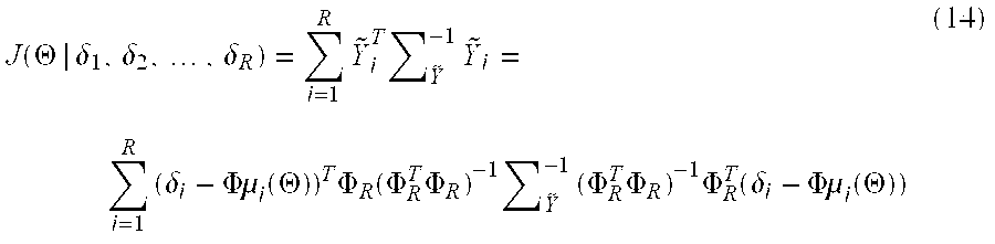
- The objective function of Equation (14) can be maximized numerically without pre-computing the gradient by use of the known optimization methods. Such a procedure simply may be a cyclical coordinate search followed, at each iteration, by an extra line search along the line connecting the current solution to the last one.
- It should be noted that a faster approach is based on Equation (5). Assume that, at some point in the computation, an estimate of the transmitter locations ({circumflex over (x)} j, ŷj) were available for j=1, . . . ,N, then Equation (5) could be used to express the Tj's in terms of known quantities and residual errors, as:

- for receivers i=1, . . . ,R, where:

- such that that D i, which is defined by Equation (15), is computable from the ({circumflex over (x)}j, ŷj).
- Averaging the vectors D i over all R receivers, results in:

- It should be noted that each component of {overscore (D)} has lower variance than the corresponding component of D i.
- The incidence matrix in Equation (17) is of rank N−1. However, a least-squares solution for Equation (17) may be expressed using the reduced incidence matrix, provided that a value for one of the T j is fixed beforehand. It should be noted that the Tj are nuisance parameters, and an estimation is not made to find their actual values, but to eliminate them such that Equation (14) can be solved for the transmitter locations. Because the Tj's are part of Equation (14) as differences, and because Equation (17) can be used to estimate the Tj's up to a single undetermined degree of freedom, a solution is thereby determined. Assume an arbitrary value for one of the Tj's (e.g., T1), T2, . . . ,TN are then determined using a reduced incidence matrix as described above. Using the same conformal partition as described above and assuming an arbitrary value, t1, for T1, the remaining Tj can be solved using a least-squares method or algorithm. Specifically, define:

- then Equation (17) results in:

- from which, after a sequence of steps similar to those above, and as known in the art, the result is:

- Now the left-hand side of Equation (20) is a zero-mean random vector with (N−1)-by-(N−1) covariance matrix:

- Because the random vector on the left-hand side of Equation (20) may be regarded as a residual, the least-squares solution is:

- The final estimate of the transmission time vector, with t 1 as its first element, can then be substituted into the objective function described above.
- Therefore, the method includes the following steps:
- Select a starting point on the plane for each of the N transmitters.
- For the current transmitter locations, compute the vector of T j's as defined in Equation (22). Select a value of t1, such as 0.
- Substitute the newly computed values of the T j into Equation (14) and numerically minimize J(Θ|δ1, δ2, . . . , δR) by varying the transmitter locations, keeping the transmission times fixed.
- If the total change in the location estimates is less than ε, then stop, otherwise compute the vector of T j's as defined in Equation (22).
- Having TOA data from a large number of transmitters increases the accuracy of the location estimates. Further, the accuracy of the method can be increased through the use of beacon transmitters. These transmitters will be exactly like the mobile transmitters in their transmission format, but their transmission burst rate are higher than that of the
mobile devices 7 because their TOA's will be used in computations more often than those of themobile devices 7. It should be noted that the beacon devices 6 have known locations and the locations of the receivers are also known. However, the time of the transmissions of the beacon devices 6 do not have to be known, such that they do not have to be synchronized to the system. The use of this embodiment is useful compared to the deployment of many receivers with overlapped coverage. - Further, in order to implement the computation using TOA measurements taken from beacon devices 6, the objective function of Equation (14) is used, and the known quantities are substituted at every iteration. The known quantities are the locations of each beacon device 6. It should be noted that the transmission times of the beacon devices 6 are not assumed to be known. If the transmission times are known, the resulting location estimates would be more accurate.
- In the asset tag location system, the algorithm described herein would be run on a central computer that would be attached to all the
base stations 3 by a low-bandwidth wired network. For every received tag transmission, everybase station 3 would send to the central computer the difference between the estimated TOA of the tag transmission and the estimated TOA of the last beacon transmission for every beacon device 6. If the beacon devices 6 transmit a burst every T milliseconds, then thebase stations 3 is configured to time out and represent an interval of duration T milliseconds to a high enough degree of precision that the TOA estimation error is the dominant error in the measurements. This goal will be achieved if the error in the timekeeping is less than 10% of the variance of the measurement error of the differences of tag and beacon TOA's. - It should be noted that the beacon transmissions can overlap, because there are a multiplicity of them in a fixed interval, and because of the time for the transmissions to occur. This overlap does not result in any problem in the various embodiments of the present invention, because the TR/DH modulation scheme used in the transmissions allows the times of arrival from overlapping transmissions to be independently measured, without interference between the measurements.
- One source of additional information for error reduction is the use of floor-plan constraints. The location algorithm can be equipped with a “map” of the hospital which describes each possible location with a quantity representing the likelihood that a patient or piece of equipment might be there. This could be used, for example, to construct an a priori distribution in an explicitly Bayesian location estimation scheme. Such an a priori distribution would have relatively large values associated with allowable tag locations and small or zero values associated with tag locations that were not physically possible. The log likelihood function of (7) would be modified by the addition of the log of the a priori distribution, which would produce the log of the a posteriori distribution. The addition of the log a priori distribution would have the effect of adding a penalty function to the objective function in the numerical optimization procedure, which might modify the location of the maximum. The “maximum a posteriori probability” estimate found by locating the mode of the a posteriori distribution will incorporate the available knowledge of the floor plan.
- In one embodiment, a location estimation system comprises a plurality of
base stations 3 distributed within the tracking area and connected by cabling to a centrally located processor. The system also comprises a plurality of fixed beacon transmitters distributed within the tracking area, the locations of which are known to the system. A mobile asset tag transmits a transmitted reference, delay-hopped UWB signal made up of pulse pairs according to the modulation method described above. The plurality of fixed beacon transmitters also transmit such signals, and their transmissions are not synchronized to the location estimation system in any way. The transmissions are RF bursts, which are structured as packets of binary information using the TR/DH modulation scheme. At least part of the information contained in each such packet is a unique identifier of the transmitter that originated the RF burst. Assuming that an asset tag transmission and at least one fixed beacon transmission is received by at least threebase stations 3, the centrally located processor can solve for the asset tag's (x,y) or (length, width) position by the algorithm given above. - In accordance with another embodiment, the system and method of the present invention monitors physiological data (e.g., cardiac information from heart patients) of the patients carrying
mobile devices 7. Configured in this manner, such a system would be a medical telemetry system that uses TR/DH communications to transmit EKG and other physiological data from patient data transmitters worn by ambulatory patients. These transmissions would be received by antennas located all over the hospital, and the transmitted waveforms would be displayed at a central station for monitoring. - In this application, the
mobile devices 7 transmit the physiological data in the TR/DH-UWB modulation format to enable thebase station 3 to perform tracking and patient monitoring functions simultaneously, or serially, if desired. If known-data fields are embedded in the TH/DH-UWB transmission, then these fields can be treated by thebase stations 3 in the same way that the asset tag bursts are treated. Their TOA's can be estimated and compared to the TOA's of beacon transmissions. These differences can be sent to acentral processor 1 for estimation of the location of the transmitter in the same way as the asset tag data. - Advantageously, unlike conventional TDOA systems that use a distributed system clock, the systems described hereinabove use fixed transmitters placed at known locations in the tracking environment. Each fixed transmitter operates on its own local clock that does not have to be synchronized with a system clock. The fixed transmitters send message packets at regular time intervals, and the difference in arrival time between the fixed transmitter packet and the mobile tag transmitter packet is measured in each receiver using the receiver's local clock. The arrival time difference is then sent via a local area network to the location processor where it is used to compute the mobile tag location using a maximum likelihood algorithm.
- The fixed transmitters replace a distributed system clock and are used to characterize the local multipath environment, temperature and humidity variations. A separate TOA packet is not transmitted to the location processor to perform calibration because the time difference between the fixed and mobile packets is transmitted. This reduces the use of LAN bandwidth in the system. In addition, special searching or triggering of the received signal to detect the direct path of the transmitted RF signal does not have to be performed. The receiver provides a signal that represents the average multipath signal from the local environment, which is compared to that received from a fixed transmitter in the same general area.
- While the invention has been described in terms of exemplary embodiments, those skilled in the art will recognize that the exemplary embodiments of the invention can be practiced with modifications within the spirit and scope of the appended claims.
Claims (23)
Priority Applications (1)
| Application Number | Priority Date | Filing Date | Title |
|---|---|---|---|
| US10/609,891 US7499711B2 (en) | 2001-10-09 | 2003-06-30 | Transmitter location for ultra-wideband, transmitted-reference CDMA communication system |
Applications Claiming Priority (2)
| Application Number | Priority Date | Filing Date | Title |
|---|---|---|---|
| US09/973,140 US7269427B2 (en) | 2001-10-09 | 2001-10-09 | Transmitter location for ultra-wideband, transmitted-reference CDMA communication system |
| US10/609,891 US7499711B2 (en) | 2001-10-09 | 2003-06-30 | Transmitter location for ultra-wideband, transmitted-reference CDMA communication system |
Related Parent Applications (1)
| Application Number | Title | Priority Date | Filing Date |
|---|---|---|---|
| US09/973,140 Continuation-In-Part US7269427B2 (en) | 2001-10-09 | 2001-10-09 | Transmitter location for ultra-wideband, transmitted-reference CDMA communication system |
Publications (2)
| Publication Number | Publication Date |
|---|---|
| US20040002347A1 true US20040002347A1 (en) | 2004-01-01 |
| US7499711B2 US7499711B2 (en) | 2009-03-03 |
Family
ID=25520547
Family Applications (2)
| Application Number | Title | Priority Date | Filing Date |
|---|---|---|---|
| US09/973,140 Expired - Fee Related US7269427B2 (en) | 2001-10-09 | 2001-10-09 | Transmitter location for ultra-wideband, transmitted-reference CDMA communication system |
| US10/609,891 Expired - Fee Related US7499711B2 (en) | 2001-10-09 | 2003-06-30 | Transmitter location for ultra-wideband, transmitted-reference CDMA communication system |
Family Applications Before (1)
| Application Number | Title | Priority Date | Filing Date |
|---|---|---|---|
| US09/973,140 Expired - Fee Related US7269427B2 (en) | 2001-10-09 | 2001-10-09 | Transmitter location for ultra-wideband, transmitted-reference CDMA communication system |
Country Status (3)
| Country | Link |
|---|---|
| US (2) | US7269427B2 (en) |
| JP (1) | JP4815093B2 (en) |
| DE (1) | DE10246922B4 (en) |
Cited By (43)
| Publication number | Priority date | Publication date | Assignee | Title |
|---|---|---|---|---|
| US20030202537A1 (en) * | 2001-09-26 | 2003-10-30 | General Atomics | Method and apparatus for data transfer using a time division multiple frequency scheme supplemented with polarity modulation |
| US20040008729A1 (en) * | 2001-09-26 | 2004-01-15 | General Atomics | Method and apparatus for data transfer using a time division multiple frequency scheme with additional modulation |
| US20040028011A1 (en) * | 2001-09-26 | 2004-02-12 | General Atomics | Method and apparatus for adapting signaling to maximize the efficiency of spectrum usage for multi-band systems in the presence of interference |
| US20040214585A1 (en) * | 2003-04-24 | 2004-10-28 | Olaker David A. | Locating method and system |
| EP1553426A1 (en) * | 2004-01-08 | 2005-07-13 | Institut de Microtechnique de l'Université de Neuchâtel | Method and receiver apparatus for wireless data communication with Ultra Wide Band time coded signals |
| US6933888B1 (en) * | 2004-06-14 | 2005-08-23 | Bae Systems Information And Electronic Systems Integration Inc. | Multi-ship coherent geolocation system |
| US20050232371A1 (en) * | 2001-09-26 | 2005-10-20 | General Atomics | Method and apparatus for data transfer using wideband bursts |
| US20050275588A1 (en) * | 2004-05-25 | 2005-12-15 | Richard Schiffmiller | Coherent geolocation system |
| NL1026919C2 (en) * | 2004-08-27 | 2006-02-28 | Nedap Agri B V | Ultra-wide-band system for determining animals. |
| US20070176826A1 (en) * | 2004-06-07 | 2007-08-02 | Commissariat A L'energie Atomique | Ulb location system for rescuing avalanche victims |
| US20080075151A1 (en) * | 2006-09-27 | 2008-03-27 | Hitachi, Ltd. | Receiver, receiver for positioning system using the same, and positioning method |
| US20080204322A1 (en) * | 2003-11-03 | 2008-08-28 | Gordon Kenneth Andrew Oswald | Determining Positional Information |
| US20080309557A1 (en) * | 2007-06-12 | 2008-12-18 | Mailaender Laurence E | Facilitating mobile station location using a ground-based cellular network |
| US20100127934A1 (en) * | 2008-11-26 | 2010-05-27 | Electronics And Telecommunications Research Institute | Positioning system, communication signal receiver for positioning system, and position calculation method |
| WO2010077819A1 (en) * | 2008-12-30 | 2010-07-08 | Trueposition Inc. | Method for position estimation using generalized error distributions |
| GB2472632A (en) * | 2009-08-13 | 2011-02-16 | Spinnaker Int Ltd | Adjusting an operating mode of a security container in response to an unexpected received radio signal |
| CN102253367A (en) * | 2011-04-01 | 2011-11-23 | 长春理工大学 | Ultrasonic wave based indoor three-dimensional positioning system and method |
| US20120086607A1 (en) * | 2005-12-23 | 2012-04-12 | Multispectral Solutions, Inc. | Wireless time reference system and method |
| US8284027B2 (en) | 2004-03-17 | 2012-10-09 | Brother Kogyo Kabushiki Kaisha | Position detecting system, responder and interrogator, wireless communication system, position detecting method, position detecting program, and information recording medium |
| CN101120513B (en) * | 2005-01-28 | 2013-01-23 | 电信学校集团国家电信研究院 | Uwb receiver and data transmission method and system |
| FR2986680A1 (en) * | 2012-02-07 | 2013-08-09 | Sigfox Wireless | METHOD FOR SYNCHRONIZING TIME MEASUREMENTS CARRIED OUT IN A RADIOCOMMUNICATION NETWORK FOR GEOLOCATION |
| FR2987136A1 (en) * | 2012-02-17 | 2013-08-23 | St Microelectronics Sa | METHOD FOR LOCATING AN OBJECT |
| US20140287772A1 (en) * | 2011-02-03 | 2014-09-25 | Realcell Limited | System and method for locating a cellular communication device |
| GB2512497A (en) * | 2013-03-26 | 2014-10-01 | Secr Defence | Separating an unknown radar signal out from multiple unknown radar signals |
| US20140368321A1 (en) * | 2013-06-12 | 2014-12-18 | Qualcomm Incorporated | Ultra-wideband ranging waveform |
| US20160365289A1 (en) * | 2009-01-09 | 2016-12-15 | Taiwan Semiconductor Manufacturing Company, Ltd. | Method for Manufacturing A Dual Work Function Semiconductor Device and the Semiconductor Device Made Thereof |
| US20170309165A1 (en) * | 2007-11-09 | 2017-10-26 | Proxense, Llc | Proximity-Sensor Supporting Multiple Application Services |
| CN107422300A (en) * | 2017-09-05 | 2017-12-01 | 芜湖华创光电科技有限公司 | It is a kind of to coordinate wireless communication terminal signal step-out time extracting method to non- |
| US10469456B1 (en) | 2007-12-19 | 2019-11-05 | Proxense, Llc | Security system and method for controlling access to computing resources |
| US10698989B2 (en) | 2004-12-20 | 2020-06-30 | Proxense, Llc | Biometric personal data key (PDK) authentication |
| US10764044B1 (en) | 2006-05-05 | 2020-09-01 | Proxense, Llc | Personal digital key initialization and registration for secure transactions |
| US10909229B2 (en) | 2013-05-10 | 2021-02-02 | Proxense, Llc | Secure element as a digital pocket |
| US10943471B1 (en) | 2006-11-13 | 2021-03-09 | Proxense, Llc | Biometric authentication using proximity and secure information on a user device |
| US10971251B1 (en) | 2008-02-14 | 2021-04-06 | Proxense, Llc | Proximity-based healthcare management system with automatic access to private information |
| GB2588988A (en) * | 2019-11-16 | 2021-05-19 | Unipart Group Ltd | Time difference of arrival calculation |
| US11080378B1 (en) | 2007-12-06 | 2021-08-03 | Proxense, Llc | Hybrid device having a personal digital key and receiver-decoder circuit and methods of use |
| US11095640B1 (en) | 2010-03-15 | 2021-08-17 | Proxense, Llc | Proximity-based system for automatic application or data access and item tracking |
| US11113482B1 (en) | 2011-02-21 | 2021-09-07 | Proxense, Llc | Implementation of a proximity-based system for object tracking and automatic application initialization |
| US11120449B2 (en) | 2008-04-08 | 2021-09-14 | Proxense, Llc | Automated service-based order processing |
| US11206664B2 (en) | 2006-01-06 | 2021-12-21 | Proxense, Llc | Wireless network synchronization of cells and client devices on a network |
| US11258791B2 (en) | 2004-03-08 | 2022-02-22 | Proxense, Llc | Linked account system using personal digital key (PDK-LAS) |
| US11546325B2 (en) | 2010-07-15 | 2023-01-03 | Proxense, Llc | Proximity-based system for object tracking |
| US11553481B2 (en) | 2006-01-06 | 2023-01-10 | Proxense, Llc | Wireless network synchronization of cells and client devices on a network |
Families Citing this family (108)
| Publication number | Priority date | Publication date | Assignee | Title |
|---|---|---|---|---|
| US6519464B1 (en) * | 2000-12-14 | 2003-02-11 | Pulse-Link, Inc. | Use of third party ultra wideband devices to establish geo-positional data |
| US20040002346A1 (en) * | 2000-12-14 | 2004-01-01 | John Santhoff | Ultra-wideband geographic location system and method |
| US6968219B2 (en) | 2001-08-15 | 2005-11-22 | Qualcomm, Incorporated | Method for reducing power consumption in bluetooth and CDMA modes of operation |
| US7269427B2 (en) * | 2001-10-09 | 2007-09-11 | General Electric Company | Transmitter location for ultra-wideband, transmitted-reference CDMA communication system |
| US7050483B2 (en) * | 2001-12-13 | 2006-05-23 | Motorola, Inc. | Low-cost two-stage receiver system for DS-CDMA |
| AU2003220600A1 (en) * | 2002-03-27 | 2003-10-13 | Uraxs Communications, Inc. | Remote ultrawide band communication system with short messaging and other functions |
| US20060166617A1 (en) * | 2002-08-09 | 2006-07-27 | Nokia Corporation | Broadcast data processing |
| US7626958B2 (en) * | 2002-12-05 | 2009-12-01 | The Boeing Company | Serial port multiplexing protocol |
| US7206365B2 (en) * | 2003-01-24 | 2007-04-17 | Via Technologies Inc | Decision sequence generating method and associated receiver with a decision feedback equalizer |
| FR2851860B1 (en) * | 2003-02-28 | 2005-04-15 | Suisse Electronique Microtech | METHOD OF MITIGATING THE INFLUENCE OF INTERFERENCE PRODUCED BY RADIO GUSTING RADIO TRANSMISSION SYSTEMS ON UWB COMMUNICATIONS |
| US7342972B1 (en) * | 2003-03-08 | 2008-03-11 | Regents Of The University Of Minnesota | Timing synchronization using dirty templates in ultra wideband (UWB) communications |
| US7496128B2 (en) | 2003-03-08 | 2009-02-24 | Regents Of The University Of Minnesota | Multi-user interference resilient ultra wideband (UWB) communication |
| US7340009B2 (en) | 2003-03-08 | 2008-03-04 | Regents Of The University Of Minnesota | Space-time coding for multi-antenna ultra-wideband transmissions |
| US20050041746A1 (en) * | 2003-08-04 | 2005-02-24 | Lowell Rosen | Software-defined wideband holographic communications apparatus and methods |
| US20050084033A1 (en) * | 2003-08-04 | 2005-04-21 | Lowell Rosen | Scalable transform wideband holographic communications apparatus and methods |
| US20050100076A1 (en) * | 2003-08-04 | 2005-05-12 | Gazdzinski Robert F. | Adaptive holographic wideband communications apparatus and methods |
| US7676194B2 (en) * | 2003-08-22 | 2010-03-09 | Rappaport Theodore S | Broadband repeater with security for ultrawideband technologies |
| US8385985B2 (en) | 2003-11-25 | 2013-02-26 | Qualcomm Incorporated | Method for reducing power consumption in a multi-mode device |
| US7356618B2 (en) * | 2003-12-31 | 2008-04-08 | Intel Corporation | Method and system for synchronizing platform clocks in a distributed wireless platform |
| US7266713B2 (en) * | 2004-01-09 | 2007-09-04 | Intel Corporation | Apparatus and method for adaptation of time synchronization of a plurality of multimedia streams |
| US7174141B2 (en) * | 2004-04-30 | 2007-02-06 | Nokia Corporation | Apparatus, and associated method, for facilitating communications in a radio communication system through use of ultrawide band signals |
| GB0416731D0 (en) * | 2004-07-27 | 2004-09-01 | Ubisense Ltd | Location system |
| KR100663530B1 (en) * | 2004-08-30 | 2007-01-02 | 삼성전자주식회사 | Apparatus for transmitting/receiving an emergent sos call using uwb signal and method therefor |
| US8369264B2 (en) | 2005-10-28 | 2013-02-05 | Skyhook Wireless, Inc. | Method and system for selecting and providing a relevant subset of Wi-Fi location information to a mobile client device so the client device may estimate its position with efficient utilization of resources |
| US7436909B2 (en) * | 2004-11-15 | 2008-10-14 | Mitsubishi Electric Research Laboratories, Inc. | Method for estimating time of arrival of received signals for ultra wide band impulse radio systems |
| JP4618082B2 (en) * | 2004-11-19 | 2011-01-26 | パナソニック株式会社 | Transmitting apparatus, receiving apparatus, and communication system |
| EP1666912A1 (en) * | 2004-12-01 | 2006-06-07 | Abatec Electronic AG | Method and system for determining the position of an object |
| JP4693405B2 (en) * | 2004-12-17 | 2011-06-01 | 株式会社日立製作所 | NODE POSITIONING SYSTEM, WIRELESS BASE STATION, AND POSITION MEASURING METHOD |
| US7573933B2 (en) * | 2005-01-04 | 2009-08-11 | Mitsubishi Electric Research Laboratories, Inc. | Adaptive delay adjustment for transmitted reference impulse radio systems |
| US7403746B2 (en) * | 2005-01-04 | 2008-07-22 | Mitsubishi Electric Research Laboratories, Inc. | Adaptive frame durations for time-hopped impulse radio systems |
| US7443303B2 (en) | 2005-01-10 | 2008-10-28 | Hill-Rom Services, Inc. | System and method for managing workflow |
| JP2006226740A (en) * | 2005-02-16 | 2006-08-31 | Hitachi Ltd | Positioning system and radio base station |
| KR100740702B1 (en) * | 2005-02-17 | 2007-07-18 | 학교법인 현동학원 | Method and apparatus for detecting direct path signal in the presence of multipath in time-modulated UWB propagation |
| EP2503832B1 (en) | 2005-02-22 | 2019-08-21 | Skyhook Wireless, Inc. | Method for calculating the position of WiFi-enabled devices |
| US7986723B2 (en) * | 2005-07-06 | 2011-07-26 | National Institute Of Information And Communications Technology | Delay estimation apparatus and method |
| US7411937B2 (en) * | 2005-08-09 | 2008-08-12 | Agilent Technologies, Inc. | Time synchronization system and method for synchronizing locating units within a communication system using a known external signal |
| US20070225879A1 (en) * | 2006-03-22 | 2007-09-27 | French John R | System and method for monitoring and managing an environment |
| KR100714089B1 (en) * | 2006-03-24 | 2007-05-02 | 삼성네트웍스 주식회사 | Local area positioning system capable of exchanging data and rf mobile device used therein |
| SG136813A1 (en) | 2006-04-11 | 2007-11-29 | Sony Corp | A method for estimating one or more parameters of a ultra wideband signal and a receiver system for receiving ultra wideband signals |
| DE102006040497A1 (en) * | 2006-08-30 | 2008-03-27 | Siemens Ag | Method and device for time-based positioning using a triggered or self-triggering reference signal |
| KR100775858B1 (en) * | 2006-11-07 | 2007-11-13 | 한국전자통신연구원 | System and method for environment analysis for indoor wireless location |
| US8014425B2 (en) * | 2006-11-16 | 2011-09-06 | Qualcomm Incorporated | Multiple access techniques for a wireless communiation medium |
| KR100897413B1 (en) | 2006-12-04 | 2009-05-14 | 한국전자통신연구원 | Device and method for perceiving location of target |
| US7970047B2 (en) * | 2006-12-27 | 2011-06-28 | Lawrence Livermore National Security, Llc | UWB channel estimation using new generating TR transceivers |
| US8208939B2 (en) | 2007-02-05 | 2012-06-26 | Aeroscout Ltd. | Dual bandwidth time difference of arrival (TDOA) system |
| WO2008116168A1 (en) * | 2007-03-21 | 2008-09-25 | Jadi, Inc. | Navigation unit and base station |
| US8098150B2 (en) * | 2007-05-25 | 2012-01-17 | Palo Alto Research Center Incorporated | Method and system for locating devices with embedded location tags |
| US20080309389A1 (en) * | 2007-06-15 | 2008-12-18 | French John R | System for preventing shopping cart push-out theft |
| KR101371820B1 (en) * | 2007-09-18 | 2014-03-07 | 엘지전자 주식회사 | Method and apparatus for displaying position using Ultra Wide Band |
| KR101371806B1 (en) * | 2007-09-18 | 2014-03-07 | 엘지전자 주식회사 | Method and apparatus for controlling souund output using Ultra Wide Band |
| US7893876B2 (en) | 2007-11-01 | 2011-02-22 | Carefusion 303, Inc. | System and method for determining locations of medical devices |
| JP5524073B2 (en) * | 2007-11-26 | 2014-06-18 | ラウンドトリップ・エルエルシー | Tamper-proof freight container locator system |
| FR2925169B1 (en) * | 2007-12-18 | 2012-03-09 | Commissariat Energie Atomique | METHOD AND SYSTEM FOR ASSISTING ENVIRONMENTAL CHARACTERIZATION WITH ULTRA BROADBAND RADIO FREQUENCY SIGNALS. |
| KR101437921B1 (en) | 2008-02-13 | 2014-09-12 | 삼성전자주식회사 | Indoor Location System and method thereof |
| KR100954169B1 (en) | 2008-02-27 | 2010-04-20 | 부산대학교 산학협력단 | TDOA based localization system, localization method in port logistics environment |
| US7843330B2 (en) * | 2008-04-15 | 2010-11-30 | General Electric Company | Interactive patient management system and method |
| US7864045B2 (en) * | 2008-09-12 | 2011-01-04 | Roundtrip Llc | Locator inventory system |
| KR101042343B1 (en) | 2008-11-12 | 2011-06-17 | 동명대학교산학협력단 | The position recognition system of a vehicle in a harbor using a uwb sensor |
| EP2375968B1 (en) * | 2008-12-15 | 2018-11-14 | Medtronic Monitoring, Inc. | Patient monitoring systems and methods |
| CN101494874B (en) * | 2009-03-03 | 2011-03-16 | 华为终端有限公司 | Method and device for estimating TOA |
| US9357921B2 (en) * | 2009-10-16 | 2016-06-07 | At&T Intellectual Property I, Lp | Wearable health monitoring system |
| US8159387B1 (en) * | 2010-03-15 | 2012-04-17 | The United States Of America As Represented By The Secretary Of The Navy | Multi-transmitter interferometry |
| US9253605B2 (en) | 2010-03-24 | 2016-02-02 | Skyhook Wireless, Inc. | System and method for resolving multiple location estimate conflicts in a WLAN-positioning system |
| US8185120B2 (en) | 2010-03-26 | 2012-05-22 | Microsoft Corporation | Cellular service with improved service availability |
| WO2011156549A2 (en) | 2010-06-11 | 2011-12-15 | Skyhook Wireless, Inc. | Methods of and systems for measuring beacon stability of wireless access points |
| US11175375B2 (en) | 2010-11-12 | 2021-11-16 | Position Imaging, Inc. | Position tracking system and method using radio signals and inertial sensing |
| US10416276B2 (en) | 2010-11-12 | 2019-09-17 | Position Imaging, Inc. | Position tracking system and method using radio signals and inertial sensing |
| US9945940B2 (en) | 2011-11-10 | 2018-04-17 | Position Imaging, Inc. | Systems and methods of wireless position tracking |
| US9933509B2 (en) * | 2011-11-10 | 2018-04-03 | Position Imaging, Inc. | System for tracking an object using pulsed frequency hopping |
| US10269182B2 (en) | 2012-06-14 | 2019-04-23 | Position Imaging, Inc. | RF tracking with active sensory feedback |
| US10180490B1 (en) | 2012-08-24 | 2019-01-15 | Position Imaging, Inc. | Radio frequency communication system |
| US8995228B2 (en) | 2012-10-22 | 2015-03-31 | Symbol Technologies, Inc. | Ultrasonic locationing using only time difference of arrival measurements |
| US10234539B2 (en) | 2012-12-15 | 2019-03-19 | Position Imaging, Inc. | Cycling reference multiplexing receiver system |
| US8712690B1 (en) | 2013-01-11 | 2014-04-29 | Intermec Ip Corp. | Systems, methods, and apparatus to determine physical location and routing within a field of low power beacons |
| US10856108B2 (en) | 2013-01-18 | 2020-12-01 | Position Imaging, Inc. | System and method of locating a radio frequency (RF) tracking device using a calibration routine |
| US9482741B1 (en) | 2013-01-18 | 2016-11-01 | Position Imaging, Inc. | System and method of locating a radio frequency (RF) tracking device using a calibration routine |
| WO2014120012A1 (en) * | 2013-01-31 | 2014-08-07 | Nederlandse Organisatie Voor Toegepast-Natuurwetenschappelijk Onderzoek Tno | Determining a position of a mobile communication device |
| US9338819B2 (en) * | 2013-05-29 | 2016-05-10 | Medtronic Minimed, Inc. | Variable data usage personal medical system and method |
| US9830424B2 (en) | 2013-09-18 | 2017-11-28 | Hill-Rom Services, Inc. | Bed/room/patient association systems and methods |
| US10634761B2 (en) | 2013-12-13 | 2020-04-28 | Position Imaging, Inc. | Tracking system with mobile reader |
| US9497728B2 (en) | 2014-01-17 | 2016-11-15 | Position Imaging, Inc. | Wireless relay station for radio frequency-based tracking system |
| US10200819B2 (en) | 2014-02-06 | 2019-02-05 | Position Imaging, Inc. | Virtual reality and augmented reality functionality for mobile devices |
| EP2983156B1 (en) * | 2014-08-06 | 2019-07-24 | Secure-IC SAS | System and method for circuit protection |
| US10115253B2 (en) * | 2014-08-15 | 2018-10-30 | Collateral Opportunities, Llc | Electronic location identiication and tracking system with beacon clustering |
| US10642560B2 (en) | 2015-02-13 | 2020-05-05 | Position Imaging, Inc. | Accurate geographic tracking of mobile devices |
| US11132004B2 (en) | 2015-02-13 | 2021-09-28 | Position Imaging, Inc. | Spatial diveristy for relative position tracking |
| US10324474B2 (en) | 2015-02-13 | 2019-06-18 | Position Imaging, Inc. | Spatial diversity for relative position tracking |
| US11416805B1 (en) | 2015-04-06 | 2022-08-16 | Position Imaging, Inc. | Light-based guidance for package tracking systems |
| US10148918B1 (en) | 2015-04-06 | 2018-12-04 | Position Imaging, Inc. | Modular shelving systems for package tracking |
| US11501244B1 (en) | 2015-04-06 | 2022-11-15 | Position Imaging, Inc. | Package tracking systems and methods |
| US10853757B1 (en) | 2015-04-06 | 2020-12-01 | Position Imaging, Inc. | Video for real-time confirmation in package tracking systems |
| WO2017015871A1 (en) * | 2015-07-28 | 2017-02-02 | 深圳市润安科技发展有限公司 | Navigation system and navigation method for medical care site person |
| WO2017015868A1 (en) * | 2015-07-28 | 2017-02-02 | 深圳市润安科技发展有限公司 | Hospital working person positioning method and hospital working person positioning system |
| KR101708199B1 (en) * | 2015-12-24 | 2017-02-20 | 한국항공우주연구원 | System for estimating the lacation of radio source |
| US10444323B2 (en) | 2016-03-08 | 2019-10-15 | Position Imaging, Inc. | Expandable, decentralized position tracking systems and methods |
| JP6700078B2 (en) * | 2016-03-18 | 2020-05-27 | 株式会社日立ソリューションズ・クリエイト | Position information providing system and method for providing position information |
| US11436553B2 (en) | 2016-09-08 | 2022-09-06 | Position Imaging, Inc. | System and method of object tracking using weight confirmation |
| US10634503B2 (en) | 2016-12-12 | 2020-04-28 | Position Imaging, Inc. | System and method of personalized navigation inside a business enterprise |
| US10455364B2 (en) | 2016-12-12 | 2019-10-22 | Position Imaging, Inc. | System and method of personalized navigation inside a business enterprise |
| US10634506B2 (en) | 2016-12-12 | 2020-04-28 | Position Imaging, Inc. | System and method of personalized navigation inside a business enterprise |
| US11120392B2 (en) | 2017-01-06 | 2021-09-14 | Position Imaging, Inc. | System and method of calibrating a directional light source relative to a camera's field of view |
| CN107202973A (en) * | 2017-05-19 | 2017-09-26 | 中国石油化工股份有限公司 | Method based on ultra wide band energy spectrum characteristic vector locating personnel |
| US11419150B2 (en) * | 2017-10-30 | 2022-08-16 | Sony Corporation | Terminal device infrastructure equipment and methods for determining a spatial position of the terminal based on received signals |
| WO2020061276A1 (en) | 2018-09-21 | 2020-03-26 | Position Imaging, Inc. | Machine-learning-assisted self-improving object-identification system and method |
| US11089232B2 (en) | 2019-01-11 | 2021-08-10 | Position Imaging, Inc. | Computer-vision-based object tracking and guidance module |
| US11911325B2 (en) | 2019-02-26 | 2024-02-27 | Hill-Rom Services, Inc. | Bed interface for manual location |
| CN111277958A (en) * | 2020-01-13 | 2020-06-12 | 张苏 | Label position determining method and device |
| CN112285652B (en) * | 2020-10-28 | 2022-06-07 | 浙江大学 | Underwater glider positioning method utilizing single beacon virtual arrival time difference |
Citations (10)
| Publication number | Priority date | Publication date | Assignee | Title |
|---|---|---|---|---|
| US5987329A (en) * | 1997-07-30 | 1999-11-16 | Ericsson Inc | System and method for mobile telephone location measurement using a hybrid technique |
| US6111536A (en) * | 1998-05-26 | 2000-08-29 | Time Domain Corporation | System and method for distance measurement by inphase and quadrature signals in a radio system |
| US6275705B1 (en) * | 1995-12-22 | 2001-08-14 | Cambridge Positioning Systems Ltd. | Location and tracking system |
| US6300904B1 (en) * | 1999-06-09 | 2001-10-09 | Honeywell International Inc. | Narrowband based navigation scheme |
| US20010053175A1 (en) * | 2000-01-04 | 2001-12-20 | Hoctor Ralph Thomas | Ultra-wideband communications system |
| US6360078B1 (en) * | 1998-12-23 | 2002-03-19 | Nortel Networks Limited | Method of compensating for group time delay asymmetry in a radio receiver |
| US6466125B1 (en) * | 1998-03-23 | 2002-10-15 | Time Domain Corporation | System and method using impulse radio technology to track and monitor people needing health care |
| US6473038B2 (en) * | 2001-01-05 | 2002-10-29 | Motorola, Inc. | Method and apparatus for location estimation |
| US20030013146A1 (en) * | 2001-05-02 | 2003-01-16 | Jay Werb | Hybrid real time locating system and methodology |
| US7269427B2 (en) * | 2001-10-09 | 2007-09-11 | General Electric Company | Transmitter location for ultra-wideband, transmitted-reference CDMA communication system |
Family Cites Families (20)
| Publication number | Priority date | Publication date | Assignee | Title |
|---|---|---|---|---|
| US4215345A (en) * | 1978-08-31 | 1980-07-29 | Nasa | Interferometric locating system |
| US4641317A (en) | 1984-12-03 | 1987-02-03 | Charles A. Phillips | Spread spectrum radio transmission system |
| JPH08146110A (en) | 1994-11-16 | 1996-06-07 | Clarion Co Ltd | Location measuring unit |
| US5933079A (en) * | 1995-09-01 | 1999-08-03 | Remote Data Systems, Inc. | Signal discriminator and positioning system |
| US5883598A (en) * | 1995-12-15 | 1999-03-16 | Signatron Technology Corporation | Position location system and method |
| US5774492A (en) * | 1996-08-02 | 1998-06-30 | General Electric Company | Low-complexity direct conversion receiver for delay-and-correlate transmitted reference signaling |
| US5952969A (en) * | 1997-08-18 | 1999-09-14 | Telefonakiebolaget L M Ericsson (Publ) | Method and system for determining the position of mobile radio terminals |
| FI974153A (en) * | 1997-11-06 | 1999-05-07 | Nokia Mobile Phones Ltd | Procedure and arrangement for determining the location of a mobile station |
| US6054950A (en) * | 1998-01-26 | 2000-04-25 | Multispectral Solutions, Inc. | Ultra wideband precision geolocation system |
| US6469628B1 (en) * | 1998-03-23 | 2002-10-22 | Time Domain Corporation | System and method for using impulse radio technology in the farming field |
| US6230018B1 (en) * | 1998-05-14 | 2001-05-08 | Nortel Networks Limited | Devices and processing in a mobile radio communication network having calibration terminals |
| US6539229B1 (en) * | 1998-08-20 | 2003-03-25 | Sony Corporation | System and method for mobile location detection in synchronous wireless systems |
| US6246882B1 (en) * | 1998-12-22 | 2001-06-12 | Telefonaktiebolaget Lm Ericsson (Publ) | Wide area item tracking system |
| US6334059B1 (en) * | 1999-01-08 | 2001-12-25 | Trueposition, Inc. | Modified transmission method for improving accuracy for e-911 calls |
| US6522882B1 (en) * | 1999-06-18 | 2003-02-18 | Nortel Networks Limited | Method and apparatus for locating a mobile transceiver in conversation state |
| US6707424B1 (en) * | 1999-10-12 | 2004-03-16 | David M. Snyder | Integrated positioning system and method |
| US6459989B1 (en) * | 2000-03-03 | 2002-10-01 | Sri International | Portable integrated indoor and outdoor positioning system and method |
| US6483461B1 (en) * | 2000-08-24 | 2002-11-19 | Time Domain Corporation | Apparatus and method for locating objects in a three-dimensional space |
| BR0115959A (en) * | 2000-11-14 | 2005-05-03 | Symbol Technologies Inc | Method and apparatus for identifying object location in communication networks |
| US6519464B1 (en) * | 2000-12-14 | 2003-02-11 | Pulse-Link, Inc. | Use of third party ultra wideband devices to establish geo-positional data |
-
2001
- 2001-10-09 US US09/973,140 patent/US7269427B2/en not_active Expired - Fee Related
-
2002
- 2002-10-08 DE DE10246922.9A patent/DE10246922B4/en not_active Expired - Fee Related
- 2002-10-09 JP JP2002295518A patent/JP4815093B2/en not_active Expired - Fee Related
-
2003
- 2003-06-30 US US10/609,891 patent/US7499711B2/en not_active Expired - Fee Related
Patent Citations (10)
| Publication number | Priority date | Publication date | Assignee | Title |
|---|---|---|---|---|
| US6275705B1 (en) * | 1995-12-22 | 2001-08-14 | Cambridge Positioning Systems Ltd. | Location and tracking system |
| US5987329A (en) * | 1997-07-30 | 1999-11-16 | Ericsson Inc | System and method for mobile telephone location measurement using a hybrid technique |
| US6466125B1 (en) * | 1998-03-23 | 2002-10-15 | Time Domain Corporation | System and method using impulse radio technology to track and monitor people needing health care |
| US6111536A (en) * | 1998-05-26 | 2000-08-29 | Time Domain Corporation | System and method for distance measurement by inphase and quadrature signals in a radio system |
| US6360078B1 (en) * | 1998-12-23 | 2002-03-19 | Nortel Networks Limited | Method of compensating for group time delay asymmetry in a radio receiver |
| US6300904B1 (en) * | 1999-06-09 | 2001-10-09 | Honeywell International Inc. | Narrowband based navigation scheme |
| US20010053175A1 (en) * | 2000-01-04 | 2001-12-20 | Hoctor Ralph Thomas | Ultra-wideband communications system |
| US6473038B2 (en) * | 2001-01-05 | 2002-10-29 | Motorola, Inc. | Method and apparatus for location estimation |
| US20030013146A1 (en) * | 2001-05-02 | 2003-01-16 | Jay Werb | Hybrid real time locating system and methodology |
| US7269427B2 (en) * | 2001-10-09 | 2007-09-11 | General Electric Company | Transmitter location for ultra-wideband, transmitted-reference CDMA communication system |
Cited By (84)
| Publication number | Priority date | Publication date | Assignee | Title |
|---|---|---|---|---|
| US7436899B2 (en) | 2001-09-26 | 2008-10-14 | General Atomics | Method and apparatus for data transfer using wideband bursts |
| US20040008729A1 (en) * | 2001-09-26 | 2004-01-15 | General Atomics | Method and apparatus for data transfer using a time division multiple frequency scheme with additional modulation |
| US20040028011A1 (en) * | 2001-09-26 | 2004-02-12 | General Atomics | Method and apparatus for adapting signaling to maximize the efficiency of spectrum usage for multi-band systems in the presence of interference |
| US7403575B2 (en) | 2001-09-26 | 2008-07-22 | General Atomics | Method and apparatus for adapting signaling to maximize the efficiency of spectrum usage for multi-band systems in the presence of interference |
| US20030202537A1 (en) * | 2001-09-26 | 2003-10-30 | General Atomics | Method and apparatus for data transfer using a time division multiple frequency scheme supplemented with polarity modulation |
| US20050232371A1 (en) * | 2001-09-26 | 2005-10-20 | General Atomics | Method and apparatus for data transfer using wideband bursts |
| US8149879B2 (en) | 2001-09-26 | 2012-04-03 | General Atomics | Method and apparatus for data transfer using a time division multiple frequency scheme supplemented with polarity modulation |
| US7321601B2 (en) * | 2001-09-26 | 2008-01-22 | General Atomics | Method and apparatus for data transfer using a time division multiple frequency scheme supplemented with polarity modulation |
| US20040214585A1 (en) * | 2003-04-24 | 2004-10-28 | Olaker David A. | Locating method and system |
| US7050817B2 (en) * | 2003-04-24 | 2006-05-23 | Locus Location Systems, Llc | Locating method and system |
| US20080204322A1 (en) * | 2003-11-03 | 2008-08-28 | Gordon Kenneth Andrew Oswald | Determining Positional Information |
| US7750841B2 (en) * | 2003-11-03 | 2010-07-06 | Cambridge Consultants Limited | Determining positional information |
| EP1553426A1 (en) * | 2004-01-08 | 2005-07-13 | Institut de Microtechnique de l'Université de Neuchâtel | Method and receiver apparatus for wireless data communication with Ultra Wide Band time coded signals |
| WO2005076032A1 (en) * | 2004-01-08 | 2005-08-18 | Institut De Microtechnique | Method and receiver device for wireless data communication through temporally coded ultra wideband signals |
| US11922395B2 (en) | 2004-03-08 | 2024-03-05 | Proxense, Llc | Linked account system using personal digital key (PDK-LAS) |
| US11258791B2 (en) | 2004-03-08 | 2022-02-22 | Proxense, Llc | Linked account system using personal digital key (PDK-LAS) |
| US8284027B2 (en) | 2004-03-17 | 2012-10-09 | Brother Kogyo Kabushiki Kaisha | Position detecting system, responder and interrogator, wireless communication system, position detecting method, position detecting program, and information recording medium |
| US20050275588A1 (en) * | 2004-05-25 | 2005-12-15 | Richard Schiffmiller | Coherent geolocation system |
| US7315280B2 (en) * | 2004-05-25 | 2008-01-01 | Bae Systems Information And Electronics Systems Integration Inc. | Coherent geolocation system |
| US20070176826A1 (en) * | 2004-06-07 | 2007-08-02 | Commissariat A L'energie Atomique | Ulb location system for rescuing avalanche victims |
| US7612717B2 (en) * | 2004-06-07 | 2009-11-03 | Commissariat A L'energie Atomique | ULB location system for rescuing avalanche victims |
| US6933888B1 (en) * | 2004-06-14 | 2005-08-23 | Bae Systems Information And Electronic Systems Integration Inc. | Multi-ship coherent geolocation system |
| GB2430100B (en) * | 2004-06-14 | 2008-04-23 | Bae Systems Information | Multi-ship coherent geolocation system |
| WO2006022548A1 (en) * | 2004-08-27 | 2006-03-02 | Nedap Agri B.V. | Ultra wide band system for animal location |
| NL1026919C2 (en) * | 2004-08-27 | 2006-02-28 | Nedap Agri B V | Ultra-wide-band system for determining animals. |
| US10698989B2 (en) | 2004-12-20 | 2020-06-30 | Proxense, Llc | Biometric personal data key (PDK) authentication |
| CN101120513B (en) * | 2005-01-28 | 2013-01-23 | 电信学校集团国家电信研究院 | Uwb receiver and data transmission method and system |
| US8742986B2 (en) * | 2005-12-23 | 2014-06-03 | Zih Corp. | Wireless time reference system and method |
| US20120086607A1 (en) * | 2005-12-23 | 2012-04-12 | Multispectral Solutions, Inc. | Wireless time reference system and method |
| US11553481B2 (en) | 2006-01-06 | 2023-01-10 | Proxense, Llc | Wireless network synchronization of cells and client devices on a network |
| US11800502B2 (en) | 2006-01-06 | 2023-10-24 | Proxense, LL | Wireless network synchronization of cells and client devices on a network |
| US11206664B2 (en) | 2006-01-06 | 2021-12-21 | Proxense, Llc | Wireless network synchronization of cells and client devices on a network |
| US11219022B2 (en) | 2006-01-06 | 2022-01-04 | Proxense, Llc | Wireless network synchronization of cells and client devices on a network with dynamic adjustment |
| US11212797B2 (en) | 2006-01-06 | 2021-12-28 | Proxense, Llc | Wireless network synchronization of cells and client devices on a network with masking |
| US11551222B2 (en) | 2006-05-05 | 2023-01-10 | Proxense, Llc | Single step transaction authentication using proximity and biometric input |
| US10764044B1 (en) | 2006-05-05 | 2020-09-01 | Proxense, Llc | Personal digital key initialization and registration for secure transactions |
| US11157909B2 (en) | 2006-05-05 | 2021-10-26 | Proxense, Llc | Two-level authentication for secure transactions |
| US11182792B2 (en) | 2006-05-05 | 2021-11-23 | Proxense, Llc | Personal digital key initialization and registration for secure transactions |
| EP1906200A1 (en) * | 2006-09-27 | 2008-04-02 | Hitachi, Ltd. | Receiver for positioning using the same, and positioning method |
| US20080075151A1 (en) * | 2006-09-27 | 2008-03-27 | Hitachi, Ltd. | Receiver, receiver for positioning system using the same, and positioning method |
| US7912481B2 (en) | 2006-09-27 | 2011-03-22 | Hitachi Ltd. | Receiver, receiver for positioning system using the same, and positioning method |
| US10943471B1 (en) | 2006-11-13 | 2021-03-09 | Proxense, Llc | Biometric authentication using proximity and secure information on a user device |
| US7667648B2 (en) * | 2007-06-12 | 2010-02-23 | Alcatel-Lucent Usa Inc. | Facilitating mobile station location using a ground-based cellular network |
| KR101135019B1 (en) * | 2007-06-12 | 2012-04-12 | 알카텔-루센트 유에스에이 인코포레이티드 | Facilitating mobile station location using a ground-based cellular network |
| US20080309557A1 (en) * | 2007-06-12 | 2008-12-18 | Mailaender Laurence E | Facilitating mobile station location using a ground-based cellular network |
| US11562644B2 (en) | 2007-11-09 | 2023-01-24 | Proxense, Llc | Proximity-sensor supporting multiple application services |
| US20170309165A1 (en) * | 2007-11-09 | 2017-10-26 | Proxense, Llc | Proximity-Sensor Supporting Multiple Application Services |
| US10769939B2 (en) * | 2007-11-09 | 2020-09-08 | Proxense, Llc | Proximity-sensor supporting multiple application services |
| US11080378B1 (en) | 2007-12-06 | 2021-08-03 | Proxense, Llc | Hybrid device having a personal digital key and receiver-decoder circuit and methods of use |
| US11086979B1 (en) | 2007-12-19 | 2021-08-10 | Proxense, Llc | Security system and method for controlling access to computing resources |
| US10469456B1 (en) | 2007-12-19 | 2019-11-05 | Proxense, Llc | Security system and method for controlling access to computing resources |
| US11727355B2 (en) | 2008-02-14 | 2023-08-15 | Proxense, Llc | Proximity-based healthcare management system with automatic access to private information |
| US10971251B1 (en) | 2008-02-14 | 2021-04-06 | Proxense, Llc | Proximity-based healthcare management system with automatic access to private information |
| US11120449B2 (en) | 2008-04-08 | 2021-09-14 | Proxense, Llc | Automated service-based order processing |
| US20100127934A1 (en) * | 2008-11-26 | 2010-05-27 | Electronics And Telecommunications Research Institute | Positioning system, communication signal receiver for positioning system, and position calculation method |
| US20110205108A1 (en) * | 2008-12-30 | 2011-08-25 | Trueposition, Inc. | Method for Position Estimation Using Generalized Error Distributions |
| WO2010077819A1 (en) * | 2008-12-30 | 2010-07-08 | Trueposition Inc. | Method for position estimation using generalized error distributions |
| US8138976B2 (en) | 2008-12-30 | 2012-03-20 | Trueposition, Inc. | Method for position estimation using generalized error distributions |
| US7956808B2 (en) | 2008-12-30 | 2011-06-07 | Trueposition, Inc. | Method for position estimation using generalized error distributions |
| US20160365289A1 (en) * | 2009-01-09 | 2016-12-15 | Taiwan Semiconductor Manufacturing Company, Ltd. | Method for Manufacturing A Dual Work Function Semiconductor Device and the Semiconductor Device Made Thereof |
| GB2472632A (en) * | 2009-08-13 | 2011-02-16 | Spinnaker Int Ltd | Adjusting an operating mode of a security container in response to an unexpected received radio signal |
| GB2472632B (en) * | 2009-08-13 | 2013-06-19 | Spinnaker Int Ltd | A security container and security systems |
| US11095640B1 (en) | 2010-03-15 | 2021-08-17 | Proxense, Llc | Proximity-based system for automatic application or data access and item tracking |
| US11546325B2 (en) | 2010-07-15 | 2023-01-03 | Proxense, Llc | Proximity-based system for object tracking |
| US20140287772A1 (en) * | 2011-02-03 | 2014-09-25 | Realcell Limited | System and method for locating a cellular communication device |
| US9544722B2 (en) * | 2011-02-03 | 2017-01-10 | Realcell Limited | System and method for locating a cellular communication device |
| US11669701B2 (en) | 2011-02-21 | 2023-06-06 | Proxense, Llc | Implementation of a proximity-based system for object tracking and automatic application initialization |
| US11113482B1 (en) | 2011-02-21 | 2021-09-07 | Proxense, Llc | Implementation of a proximity-based system for object tracking and automatic application initialization |
| US11132882B1 (en) | 2011-02-21 | 2021-09-28 | Proxense, Llc | Proximity-based system for object tracking and automatic application initialization |
| CN102253367A (en) * | 2011-04-01 | 2011-11-23 | 长春理工大学 | Ultrasonic wave based indoor three-dimensional positioning system and method |
| US20140378161A1 (en) * | 2012-02-07 | 2014-12-25 | Sigfox | Method for synchronizing time measurements carried out in a radio communication network for geolocation purposes |
| CN104115025A (en) * | 2012-02-07 | 2014-10-22 | 西格弗克斯公司 | Method for synchronizing time measurements carried out in a radio communication network for geolocation purposes |
| WO2013117670A1 (en) * | 2012-02-07 | 2013-08-15 | Sigfox | Method for synchronizing time measurements carried out in a radio communication network for geolocation purposes |
| FR2986680A1 (en) * | 2012-02-07 | 2013-08-09 | Sigfox Wireless | METHOD FOR SYNCHRONIZING TIME MEASUREMENTS CARRIED OUT IN A RADIOCOMMUNICATION NETWORK FOR GEOLOCATION |
| US9341701B2 (en) * | 2012-02-07 | 2016-05-17 | Sigfox | Method for synchronizing time measurements carried out in a radio communication network for geolocation purposes |
| FR2987136A1 (en) * | 2012-02-17 | 2013-08-23 | St Microelectronics Sa | METHOD FOR LOCATING AN OBJECT |
| US9182474B2 (en) | 2012-02-17 | 2015-11-10 | Stmicroelectronics S.A. | Method for localizing an object |
| GB2512497A (en) * | 2013-03-26 | 2014-10-01 | Secr Defence | Separating an unknown radar signal out from multiple unknown radar signals |
| GB2512497B (en) * | 2013-03-26 | 2015-08-05 | Secr Defence | Separating an unknown radar signal out from multiple unknown radar signals |
| US10909229B2 (en) | 2013-05-10 | 2021-02-02 | Proxense, Llc | Secure element as a digital pocket |
| US11914695B2 (en) | 2013-05-10 | 2024-02-27 | Proxense, Llc | Secure element as a digital pocket |
| US20140368321A1 (en) * | 2013-06-12 | 2014-12-18 | Qualcomm Incorporated | Ultra-wideband ranging waveform |
| CN107422300A (en) * | 2017-09-05 | 2017-12-01 | 芜湖华创光电科技有限公司 | It is a kind of to coordinate wireless communication terminal signal step-out time extracting method to non- |
| GB2588988A (en) * | 2019-11-16 | 2021-05-19 | Unipart Group Ltd | Time difference of arrival calculation |
Also Published As
| Publication number | Publication date |
|---|---|
| US20030069025A1 (en) | 2003-04-10 |
| US7269427B2 (en) | 2007-09-11 |
| US7499711B2 (en) | 2009-03-03 |
| JP4815093B2 (en) | 2011-11-16 |
| JP2003189353A (en) | 2003-07-04 |
| DE10246922A1 (en) | 2003-05-08 |
| DE10246922B4 (en) | 2017-05-11 |
Similar Documents
| Publication | Publication Date | Title |
|---|---|---|
| US7499711B2 (en) | Transmitter location for ultra-wideband, transmitted-reference CDMA communication system | |
| US7383053B2 (en) | Position estimation of transceivers in communication networks | |
| US7962150B2 (en) | Ultra-wideband radios for time-of-flight-ranging and network position estimation | |
| CA2384383C (en) | Method and apparatus for determining the position of a mobile communication device using low accuracy clocks | |
| McCrady et al. | Mobile ranging using low-accuracy clocks | |
| US6483461B1 (en) | Apparatus and method for locating objects in a three-dimensional space | |
| EP1682920B1 (en) | Location system and method that achieves time synchronized performance using unsynchronized receivers | |
| US6985107B2 (en) | Random antenna array interferometer for radio location | |
| US5920278A (en) | Method and apparatus for identifying, locating, tracking, or communicating with remote objects | |
| KR100917940B1 (en) | Ultra wide band navigation system with mobile base stations | |
| US20090149202A1 (en) | System and method for determination of position | |
| US20080186235A1 (en) | Multiplatform TDOA correlation interferometer geolocation | |
| US20150323642A1 (en) | Device and method for location of an rfid transmitter | |
| EP1682921B1 (en) | Location system and method that achieves time synchronized network performance with nodes divided into separate networks | |
| Segura et al. | Experimental demonstration of self-localized ultra wideband indoor mobile robot navigation system | |
| WO2007067821A2 (en) | Ultra-wideband radios for time-of-flight ranging and network position estimation | |
| US10886965B2 (en) | Orthogonal correlation signals for detection and synchronization at low SNR | |
| Hedley et al. | Accurate wireless localization in sports | |
| Bocus et al. | Low cost localisation in residential environments using high resolution CIR information | |
| US20230142169A1 (en) | Radar system and a radar method for compensating a carrier characteristic offset | |
| US7965237B2 (en) | Mobile system and method for position estimation | |
| Diao et al. | An overview of range detection techniques for wireless sensor networks | |
| Aleksandravicius et al. | High-accuracy localization of backscattering UWB tags: Implementation and experimental results | |
| Friedman et al. | Angle-of-arrival-assisted relative interferometric localization using software defined radios | |
| Zetik et al. | UWB M-sequence based radar technology for localization of first responders |
Legal Events
| Date | Code | Title | Description |
|---|---|---|---|
| AS | Assignment |
Owner name: GENERAL ELECTRIC COMPANY, NEW YORK Free format text: ASSIGNMENT OF ASSIGNORS INTEREST;ASSIGNORS:HOCTOR, RALPH THOMAS;HERSHEY, JOHN ERIK;VAN STRALEN, NICK ANDREWS;AND OTHERS;REEL/FRAME:014247/0843 Effective date: 20030630 |
|
| FEPP | Fee payment procedure |
Free format text: PAYOR NUMBER ASSIGNED (ORIGINAL EVENT CODE: ASPN); ENTITY STATUS OF PATENT OWNER: LARGE ENTITY |
|
| STCF | Information on status: patent grant |
Free format text: PATENTED CASE |
|
| CC | Certificate of correction | ||
| FPAY | Fee payment |
Year of fee payment: 4 |
|
| FPAY | Fee payment |
Year of fee payment: 8 |
|
| FEPP | Fee payment procedure |
Free format text: MAINTENANCE FEE REMINDER MAILED (ORIGINAL EVENT CODE: REM.); ENTITY STATUS OF PATENT OWNER: LARGE ENTITY |
|
| LAPS | Lapse for failure to pay maintenance fees |
Free format text: PATENT EXPIRED FOR FAILURE TO PAY MAINTENANCE FEES (ORIGINAL EVENT CODE: EXP.); ENTITY STATUS OF PATENT OWNER: LARGE ENTITY |
|
| STCH | Information on status: patent discontinuation |
Free format text: PATENT EXPIRED DUE TO NONPAYMENT OF MAINTENANCE FEES UNDER 37 CFR 1.362 |
|
| FP | Lapsed due to failure to pay maintenance fee |
Effective date: 20210303 |