US20040236500A1 - Input system based on a three-dimensional inertial navigation system and trajectory estimation method thereof - Google Patents
Input system based on a three-dimensional inertial navigation system and trajectory estimation method thereof Download PDFInfo
- Publication number
- US20040236500A1 US20040236500A1 US10/802,056 US80205604A US2004236500A1 US 20040236500 A1 US20040236500 A1 US 20040236500A1 US 80205604 A US80205604 A US 80205604A US 2004236500 A1 US2004236500 A1 US 2004236500A1
- Authority
- US
- United States
- Prior art keywords
- motion
- axis
- rotation angle
- information
- angle information
- Prior art date
- Legal status (The legal status is an assumption and is not a legal conclusion. Google has not performed a legal analysis and makes no representation as to the accuracy of the status listed.)
- Granted
Links
Images
Classifications
-
- G—PHYSICS
- G06—COMPUTING; CALCULATING OR COUNTING
- G06F—ELECTRIC DIGITAL DATA PROCESSING
- G06F3/00—Input arrangements for transferring data to be processed into a form capable of being handled by the computer; Output arrangements for transferring data from processing unit to output unit, e.g. interface arrangements
- G06F3/01—Input arrangements or combined input and output arrangements for interaction between user and computer
- G06F3/03—Arrangements for converting the position or the displacement of a member into a coded form
- G06F3/033—Pointing devices displaced or positioned by the user, e.g. mice, trackballs, pens or joysticks; Accessories therefor
- G06F3/0354—Pointing devices displaced or positioned by the user, e.g. mice, trackballs, pens or joysticks; Accessories therefor with detection of 2D relative movements between the device, or an operating part thereof, and a plane or surface, e.g. 2D mice, trackballs, pens or pucks
- G06F3/03545—Pens or stylus
-
- G—PHYSICS
- G01—MEASURING; TESTING
- G01C—MEASURING DISTANCES, LEVELS OR BEARINGS; SURVEYING; NAVIGATION; GYROSCOPIC INSTRUMENTS; PHOTOGRAMMETRY OR VIDEOGRAMMETRY
- G01C21/00—Navigation; Navigational instruments not provided for in groups G01C1/00 - G01C19/00
- G01C21/10—Navigation; Navigational instruments not provided for in groups G01C1/00 - G01C19/00 by using measurements of speed or acceleration
- G01C21/12—Navigation; Navigational instruments not provided for in groups G01C1/00 - G01C19/00 by using measurements of speed or acceleration executed aboard the object being navigated; Dead reckoning
- G01C21/16—Navigation; Navigational instruments not provided for in groups G01C1/00 - G01C19/00 by using measurements of speed or acceleration executed aboard the object being navigated; Dead reckoning by integrating acceleration or speed, i.e. inertial navigation
- G01C21/166—Mechanical, construction or arrangement details of inertial navigation systems
-
- G—PHYSICS
- G01—MEASURING; TESTING
- G01C—MEASURING DISTANCES, LEVELS OR BEARINGS; SURVEYING; NAVIGATION; GYROSCOPIC INSTRUMENTS; PHOTOGRAMMETRY OR VIDEOGRAMMETRY
- G01C21/00—Navigation; Navigational instruments not provided for in groups G01C1/00 - G01C19/00
- G01C21/10—Navigation; Navigational instruments not provided for in groups G01C1/00 - G01C19/00 by using measurements of speed or acceleration
- G01C21/12—Navigation; Navigational instruments not provided for in groups G01C1/00 - G01C19/00 by using measurements of speed or acceleration executed aboard the object being navigated; Dead reckoning
- G01C21/16—Navigation; Navigational instruments not provided for in groups G01C1/00 - G01C19/00 by using measurements of speed or acceleration executed aboard the object being navigated; Dead reckoning by integrating acceleration or speed, i.e. inertial navigation
- G01C21/183—Compensation of inertial measurements, e.g. for temperature effects
-
- G—PHYSICS
- G06—COMPUTING; CALCULATING OR COUNTING
- G06F—ELECTRIC DIGITAL DATA PROCESSING
- G06F3/00—Input arrangements for transferring data to be processed into a form capable of being handled by the computer; Output arrangements for transferring data from processing unit to output unit, e.g. interface arrangements
- G06F3/01—Input arrangements or combined input and output arrangements for interaction between user and computer
- G06F3/03—Arrangements for converting the position or the displacement of a member into a coded form
- G06F3/033—Pointing devices displaced or positioned by the user, e.g. mice, trackballs, pens or joysticks; Accessories therefor
- G06F3/0346—Pointing devices displaced or positioned by the user, e.g. mice, trackballs, pens or joysticks; Accessories therefor with detection of the device orientation or free movement in a 3D space, e.g. 3D mice, 6-DOF [six degrees of freedom] pointers using gyroscopes, accelerometers or tilt-sensors
-
- G—PHYSICS
- G06—COMPUTING; CALCULATING OR COUNTING
- G06V—IMAGE OR VIDEO RECOGNITION OR UNDERSTANDING
- G06V30/00—Character recognition; Recognising digital ink; Document-oriented image-based pattern recognition
- G06V30/10—Character recognition
- G06V30/14—Image acquisition
- G06V30/142—Image acquisition using hand-held instruments; Constructional details of the instruments
- G06V30/1423—Image acquisition using hand-held instruments; Constructional details of the instruments the instrument generating sequences of position coordinates corresponding to handwriting
-
- G—PHYSICS
- G06—COMPUTING; CALCULATING OR COUNTING
- G06V—IMAGE OR VIDEO RECOGNITION OR UNDERSTANDING
- G06V30/00—Character recognition; Recognising digital ink; Document-oriented image-based pattern recognition
- G06V30/10—Character recognition
- G06V30/22—Character recognition characterised by the type of writing
- G06V30/228—Character recognition characterised by the type of writing of three-dimensional handwriting, e.g. writing in the air
Definitions
- An apparatus consistent with the present invention relates to an input system based on a three-dimensional inertial navigation system and a trajectory estimation method thereof.
- the input system can recover writing motions as naturally done on a general plane, a free space, or a sheet of paper so as to enable users to input characters, graphics, gestures, and so on, the input system can be utilized as an excellent input system since it is excellent in the aspect of “universal purpose” and also does not require a particular learning course for use.
- the three-dimensional inertial navigation system refers to a system that detects three-axis acceleration information and three-axis angular velocity information and applies the detected information to a moving object in order to estimate positions and attitudes of the moving object in the three-dimensional space.
- the three-dimensional inertial navigation system calculates the attitudes of the object and corrects the acceleration information using an integral value of angular velocity information estimation values, accordingly, calculates velocity information by integrating the corrected acceleration information once, and calculates position information by integrating the corrected acceleration information twice.
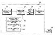
- FIG. 1 is a block diagram illustrating an input system using a conventional inertial navigation system.
- the input system using the conventional inertial navigation system includes an input part 10 and a host device 20 .
- the host device 20 displays an image corresponding to motions based on the motions from the input part 10 .
- the input part 10 includes acceleration sensors 11 , angular velocity sensors 12 , a rotation angle information-computing unit 13 , conversion-computing unit 14 , and a transmission unit 15 .
- the acceleration sensors 11 generate acceleration information A b (A bx , A by , A bz ) corresponding to motions based on the motions of the input part 10 , and output the same to the conversion-computing unit 14 .
- the subscript b in the acceleration information denotes acceleration information for a body frame of the input part and the subscripts x, y, and z denote information on x-axis, y-axis, and z-axis.
- the angular velocity sensors 12 generate angular velocity information W b (W bx , W by , W bz ) corresponding to motions based on the motions of the input part 10 , and output the same to the rotation angle information-computing unit 13 .
- the subscript b of the angular velocity information denotes angular velocity information for the body frame of the input part
- the subscripts x, y, and z denote information on x-axis, y-axis, and z-axis.
- the rotation angle information-computing unit 13 inputs angular velocity information from the angular velocity sensors 12 .
- the inputted angular velocity information is converted into rotation angle information ⁇ ( ⁇ , ⁇ , ⁇ ) through a predetermined computing process.
- the predetermined computing process for the conversion into the rotation angle information is well known to those skilled in the art, so a detailed description on the process will be omitted in the disclosure.
- the conversion-computing unit 14 inputs acceleration information and rotation angle information.
- the conversion-computing unit 14 calculates the attitudes of the input part 10 based on the rotation angle information, corrects the acceleration information based on the rotation angle information, calculates velocity information by integrating the corrected acceleration information once, and calculates position information by integrating the corrected acceleration information twice.
- Such calculations can be performed based on Equations 1, 2, and 3 as follows.
- a body frame is a frame from which acceleration information and angular velocity information can be detected in correspondence to actual motions of the input part 10 .
- a navigation frame is a reference frame for calculating information applicable for a host device 20 by applying predetermined computing matrices based on a result detected from the body frame.
- the coordinate axes for the navigation frame are referred to as X 0 , Y 0 , and Z 0 .
- Rotation angle information is as follows: The coordinate axes for the navigation frame and the body frame coincide with each other when there is no rotation at an initial time.
- X 0 , Y 0 , and Z 0 ⁇ denotes the rotation angle information for the Z 0 axis.
- ⁇ denotes rotation angle information for a Y 1 axis indicating an axis after the Y 0 axis is rotated as much as ⁇ .
- ⁇ denotes rotation angle information for a X 2 axis indicating an axis after the X 0 axis is rotated as much as ⁇ and ⁇ , respectively.
- a 3 ⁇ 3 matrix for converting a vector in the body frame into a vector in the navigation frame is as follows:
- C b n ⁇ ( ⁇ ) [ ⁇ c ⁇ ⁇ c - ⁇ c ⁇ ⁇ s + ⁇ s ⁇ ⁇ s ⁇ ⁇ c ⁇ s ⁇ ⁇ s + ⁇ c ⁇ ⁇ s ⁇ ⁇ c ⁇ ⁇ s ⁇ c + ⁇ s ⁇ ⁇ s ⁇ s - ⁇ s ⁇ c + ⁇ c ⁇ ⁇ s ⁇ ⁇ s - ⁇ s ⁇ ⁇ c + ⁇ c ⁇ ⁇ s ⁇ ⁇ s - ⁇ s ⁇ ⁇ c ⁇ ⁇ c ]
- R ⁇ ( ⁇ ) [ 1 ⁇ s ⁇ ⁇ t ⁇ c ⁇ ⁇ t 0 ⁇ c - ⁇ s 0 ⁇ s / ⁇ c ⁇ c / ⁇ c ]
- the subscripts s, c, and t stand for sine, cosine, and tangent functions, respectively, and the ⁇ denotes the rotation angle information in a 3 ⁇ 1 matrix.
- a b denotes the acceleration information in the body frame
- W b denotes the angular velocity information in the body frame
- R denotes a matrix for calculating the rotation angle information based on the angular velocity information in the body frame
- G is the gravitational acceleration
- C b n denotes a matrix for converting a vector in the body frame into a vector in the navigation frame
- position information in the navigation frame is P n
- velocity information in the navigation frame is V n
- the rotation angle information is ⁇ .
- P n , V n , A b , G, and W b are a 3 ⁇ 1 matrix, respectively
- G is a matrix of [0,0, g] T
- dP n , dV n , and d ⁇ denotes differentiations of P n , V n , and ⁇ with respect to time, respectively.
- the acceleration information and the angular velocity information for the body frame outputted from the acceleration sensors and the angular velocity sensors respectively are computed and converted into velocity information and position information for the navigation frame, and a motion image corresponding to motions in the three-dimensional space based on the conversion-computed position information is projected to an optimal projection plane, and then outputted to the transmission unit 15 .
- the transmission unit 15 outputs the projected position information to the host device 20 .
- Illustrative, non-limiting embodiments of the present invention overcome the above disadvantages and other disadvantages not described above. Also, the present invention is not required to overcome the disadvantages described above, and an illustrative, non-limiting embodiment of the present invention may not overcome any of the problems discussed above.
- An apparatus consistent with the present invention provides an input system based on a three-dimensional inertial navigation system and a trajectory estimation method thereof, capable of recovering motions in the three-dimensional space by using only three acceleration sensors without any angular velocity sensor, that is, without using both three acceleration sensors and three angular velocity sensors as in the three-dimensional inertial navigation system.
- the above aspect is achieved by providing an input system based on a three-dimensional inertial navigation system and having an input part and a host device, which detects motion position information corresponding to three-dimensional motions of the input part and outputs the detected motion position information to the host device.
- the input system comprises acceleration sensors for outputting acceleration information just before the motions (hereinafter, referred to as pre-motion acceleration information where applicable), acceleration information on the motions (hereinafter, referred to as motion acceleration information where applicable), and acceleration information just after the motions (hereinafter, referred to as post-motion acceleration information where applicable); a rotation angle information estimation-computing portion for estimating rotation angle information ⁇ , ⁇ , and ⁇ on the motions (hereinafter, referred to as motion rotation angle information where applicable) through a predetermined computing process based on the outputted pre-motion acceleration information and post-motion acceleration information; a conversion-computing unit for calculating the motion position information based on the estimated motion rotation angle information and the outputted motion acceleration information; and an optimal plane-computing unit for projecting the motion position information onto an optimal plane.
- the rotation angle information estimation-computing portion includes a first computing unit for calculating rotation angle information ⁇ 1, ⁇ 1, and ⁇ 1 just before the motions (hereinafter, referred to as pre-motion rotation angle information where applicable) and rotation angle information ⁇ 2, ⁇ 2, and ⁇ 2 just after the motions (hereinafter, referred to as post-motion rotation angle information where applicable) through a predetermined computing process based on the outputted pre-motion acceleration information and post-motion acceleration information; and a second computing unit for calculating the motion rotation angle information through a predetermined computing process based on the calculated pre-motion rotation angle information and post-motion rotation angle information.
- pre-motion rotation angle information where applicable
- post-motion rotation angle information just after the motions
- a by1 and A by2 denote the pre-motion acceleration information and the post-motion acceleration information for the Y axis respectively
- a bz1 and A bz2 denote the pre-motion acceleration information and the post-motion acceleration information for the Z axis respectively
- coordinate axes for the navigation frame are denoted as X 0 , Y 0 , and Z 0
- ⁇ 1 and ⁇ 2 denote the pre-motion rotation angle information and the post-motion rotation angle information for the Z 0 axis
- ⁇ 1 denotes the pre-motion rotation angle information for a Y 1 axis indicating an axis after the Y 0 axis is rotated as much as ⁇ 1
- ⁇ 2 denotes the post-motion rotation angle information for Y 1 axis indicating an axis after the Y 0 axis
- a bx1 and A bx2 denote the pre-motion acceleration information and the post-motion acceleration information for the X axis respectively
- a by1 and A by2 denote the pre-motion acceleration information and the post-motion acceleration information for the Y axis respectively
- a bz1 and A bz2 denote the pre-motion acceleration information and the post-motion acceleration information for the Z axis respectively
- coordinate axes for the navigation frame are denoted as X 0 , Y 0 , and Z 0
- ⁇ 1 and ⁇ 2 denote the pre-motion rotation angle information and the post-motion rotation angle information for the Z 0 axis
- ⁇ 1 denotes the pre-motion rotation angle information for a Y 1 axis indicating an axis after the Y 0 axis is rotated as much as ⁇
- the above object is achieved by providing the input system based on the three-dimensional inertial navigation system according to the present invention and having an input part and a host device, which detects motion position information corresponding to three-dimensional motions of the input part and outputs the detected motion position information to the host device.
- the input system comprises acceleration sensors for outputting motion acceleration information; a rotation angle information estimation-computing portion for estimating motion rotation angle information ⁇ , ⁇ , and ⁇ based on acceleration information based on the gravitational acceleration separated from the outputted motion acceleration information; a conversion-computing unit for calculating motion position information based on the estimated motion rotation angle information and the outputted motion acceleration information; and an optimal plane-computing unit for projecting the motion position information onto an optimal plane.
- the rotation angle information estimation-computing portion includes a separation unit for separating acceleration information based on the motions of the input part itself and acceleration information based on the gravitational acceleration from the outputted motion acceleration information based on a predetermined process; and a computing unit for calculating the motion rotation angle information through the predetermined computing process based on the acceleration information based on the separated gravitational acceleration.
- the predetermined process for separating the acceleration information based on the gravitational acceleration from the motion acceleration information is to pass the motion acceleration information through a low-pass filter.
- a bx denotes acceleration information for the X axis
- a by denotes acceleration information for the Y axis
- a bz denotes acceleration information for the Z axis
- coordinate axes for the navigation frame are denoted as X 0 , Y 0 , and Z 0
- ⁇ denotes rotation angle information for the Z 0 axis
- ⁇ denotes rotation angle information for a Y 1 axis indicating an axis after the Y 0 is rotated as much as ⁇ .
- the above object is achieved by providing a trajectory estimation method for an input system based on a three-dimensional inertial navigation system and having an input part and a host device according to the present invention, which detects motion position information corresponding to three-dimensional motions of the input part and outputs the detected motion position information to the host device.
- the method comprises steps of (a) outputting motion acceleration information, pre-motion acceleration information, and post-motion acceleration information just after the motions; (b) estimating motion rotation angle information ⁇ , ⁇ , and ⁇ through a predetermined computing process based on the outputted pre-motion acceleration information and post-motion acceleration information; (c) calculating the motion position information based on the estimated motion rotation angle information and the outputted motion acceleration information; and (d) projecting the motion position information onto an optimal plane.
- the step (b) includes steps of (b1) calculating pre-motion rotation angle information ⁇ 1, ⁇ 1, and ⁇ 1 and post-motion rotation angle information ⁇ 2, ⁇ 2, and ⁇ 2 through a predetermined computing process based on the outputted pre-motion acceleration information and post-motion acceleration information; and (b2) calculating the motion rotation angle information through a predetermined computing process based on the calculated pre-motion rotation angle information and post-motion rotation angle information.
- a by1 and A by2 denote the pre-motion acceleration information and the post-motion acceleration information for the Y axis respectively
- a bz1 and A bz2 denote the pre-motion acceleration information and the post-motion acceleration information for the Z axis respectively
- coordinate axes for the navigation frame are denoted as X 0 , Y 0 , and Z 0
- ⁇ 1 and ⁇ 2 denote the pre-motion rotation angle information and the post-motion rotation angle information for the Z 0 axis
- ⁇ 1 denotes the pre-motion rotation angle information for a Y 1 axis indicating an axis after the Y 0 axis is rotated as much as ⁇ 1
- ⁇ 2 denotes the post-motion rotation angle information for Y 1 axis indicating an axis after the Y 0 axis
- a bx1 and A bx2 denote the pre-motion acceleration information and the post-motion acceleration information for the X axis respectively
- a by1 and A by2 denote the pre-motion acceleration information and the post-motion acceleration information for the Y axis respectively
- a bz1 and A bz2 denote the pre-motion acceleration information and the post-motion acceleration information for the Z axis respectively
- coordinate axes for the navigation frame are denoted as X 0 , Y 0 , and Z 0
- ⁇ 1 and ⁇ 2 denote the pre-motion rotation angle information and the post-motion rotation angle information for the Z 0 axis
- ⁇ 1 denotes the pre-motion rotation angle information for a Y 1 axis indicating an axis after the Y 0 axis is rotated as much as ⁇
- the above object is achieved by providing a trajectory estimation method for an input system based on a three-dimensional inertial navigation system and having an input part and a host device, which detects motion position information corresponding to motions of the input part based on three-dimensional motions of the input part and outputs the detected motion position information to the host device.
- the method comprises steps of: (a) outputting motion acceleration information; (b) estimating motion rotation angle information ⁇ , ⁇ , and ⁇ based on acceleration information based on the gravitational acceleration separated from the outputted motion acceleration information; (c) calculating motion position information based on the estimated motion rotation angle information and the outputted motion acceleration information; and (d) projecting the motion position information onto an optimal plane.
- the step (b) includes steps of (b1) separating acceleration information based on the motions of the input part itself and acceleration information based on the gravitational acceleration from the outputted motion acceleration information based on a predetermined process; and (b2) calculating the motion rotation angle information through the predetermined computing process based on the acceleration information based on the separated gravitational acceleration.
- the predetermined process in the step (b1) is to pass the motion acceleration information through a low-pass filter.
- a bx denotes acceleration information for the X axis
- a by denotes acceleration information for the Y axis
- a bz denotes acceleration information for the Z axis
- coordinate axes for the navigation frame are denoted as X 0 , Y 0 , and Z 0
- ⁇ denotes rotation angle information for the Z 0 axis
- ⁇ denotes rotation angle information for a Y 1 axis indicating an axis after the Y 0 is as much as ⁇ .
- the present invention can recover the three-dimensional motions by using only the three acceleration sensors without the angular velocity sensors in the three-dimensional inertial navigation system.
- FIG. 1 is a block diagram for showing an input system using a conventional inertial navigation system
- FIG. 2 is a block diagram for showing an input system including an input part equipped with a rotation angle information estimation-computing portion according to an embodiment of the present invention
- FIG. 3 is a block diagram for showing an input system including an input part equipped with a rotation angle information estimation-computing portion according to another embodiment of the present invention
- FIG. 4A is a graph for showing acceleration information on motions outputted from acceleration sensors
- FIG. 4B is a graph for showing acceleration information in case that only the acceleration information based on the gravitational acceleration is separated from the acceleration information of FIG. 4A when a low-pass filter is provided in a separation unit;
- FIG. 5 is a flow chart for showing a trajectory estimation method for an input system of FIG. 2 according to an embodiment of the present invention
- FIG. 6 is a flow chart for showing a trajectory estimation method for an input system of FIG. 3 according to another embodiment of the present invention.
- FIG. 7A is a view for showing results of certain numbers written by an input system to which the present invention is applied;
- FIG. 7B is a view for showing results of other certain numbers written by an input system to which the present invention is applied.
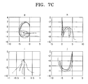
- FIG. 7C is a view for showing results of certain letters written by an input system to which the present invention is applied.
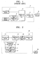
- FIG. 2 is a block diagram for showing an input system including an input part 100 equipped with a rotation angle information estimation-computing portion 120 according to an embodiment of the present invention.
- the input system has the input part 100 and a host device 300 .
- the input part 100 includes acceleration sensors 110 , the rotation angle information estimation-computing portion 120 , a conversion-computing unit 130 , an optimal plane-computing unit 135 and a transmission unit 140 .
- the acceleration sensors 110 are provided for three X, Y 1 and Z axes of a body frame of the input part 100 according to three x, y, and z axes to be based on motions of the input part 100 .
- the acceleration sensors 110 detect and output acceleration information on motions (hereinafter, referred to as motion acceleration information where applicable), acceleration information just before the motions (hereinafter, referred to as pre-motion acceleration information where applicable), and acceleration information just after the motions (hereinafter, referred to as post-motion acceleration information where applicable), respectively.
- motion acceleration information where applicable
- pre-motion acceleration information acceleration information just before the motions
- post-motion acceleration information acceleration information just after the motions
- the acceleration sensors 110 can detect acceleration information just before and after intended motions to be taken by the input part 100 .
- the pre-motion acceleration information refers to acceleration information just before intended motions.
- the post-motion acceleration information refers to acceleration information just after intended motions.
- Motion acceleration information refers to acceleration information based on intended motions to be taken by a user.
- the rotation angle information estimation-computing portion 120 computes and estimates rotation angle information based on pre-motion acceleration information and post-motion acceleration information outputted from the acceleration sensors 110 .
- the rotation angle information estimation-computing portion 120 includes a first computing unit 121 and a second computing unit 122 .
- the first computing-unit 121 inputs pre-motion acceleration information and post-motion acceleration information on the input part 100 from the acceleration sensors 110 .
- the first computing unit 121 computes ⁇ and ⁇ of rotation angle information just before motions through a predetermined computing process based on pre-motion acceleration information.
- the rotation angle information just before motions is pre-motion rotation angle information corresponding to the pre-motion acceleration information.
- the first computing unit 121 computes ⁇ and ⁇ of rotation angle information just after motions through a predetermined computing process based on post-motion acceleration information.
- the rotation angle information just after motions is post-motion rotation angle information corresponding to the post-motion acceleration information.
- acceleration information for the X axis of the body frame is denoted as A bx
- acceleration information for the Y axis of the body frame is denoted as A by
- acceleration information for the Z axis of the body frame is denoted as A bz
- rotation angle information for a Z 0 axis as ⁇
- rotation angle information for a Y 1 axis indicating an axis after a Y 0 axis is rotated as much as ⁇
- Equation 4 expresses rotation angle information ⁇ for a X 2 axis indicating an axis after the X 0 axis is rotated as much as ⁇ and ⁇ , respectively.
- ⁇ tan - 1 ⁇ ( A by A bz ) [ Equation ⁇ ⁇ 4 ]
- acceleration information for the X axis of the body frame is denoted as A bx
- acceleration information for the Y axis of the body frame is denoted as A by
- acceleration information for the Z axis of the body frame is denoted as A bz
- rotation angle information for a Z 0 axis as ⁇
- Equations 4 and 5 are formulae by which the ⁇ and ⁇ of rotation angle information can be respectively calculated from acceleration information at the state of no motion.
- the second computing unit 122 inputs the ⁇ and ⁇ of pre-motion rotation angle information computed from the first computing unit 121 .
- the second computing unit 122 inputs the ⁇ and ⁇ of post-motion rotation angle information computed from the first computing unit 121 .
- the second computing unit 122 computes the motion rotation angle information ⁇ through a predetermined computing process based on the ⁇ of the inputted pre-motion rotation angle information and the ⁇ of the inputted post-motion rotation angle information.
- the second computing unit 122 computes the motion rotation angle information ⁇ through a predetermined computing process based on the ⁇ of the inputted pre-motion rotation angle information and the ⁇ of the inputted post-motion rotation angle information.
- Equation 6 the ⁇ (t) of the motion rotation angle information
- Equation 7 the ⁇ (t) of the motion rotation angle information
- the conversion-computing unit 130 inputs motion acceleration information from the acceleration sensors 110 , and inputs motion rotation angle information estimated from the rotation angle information estimating-computing portion 120 . Based on the inputted motion acceleration information and motion rotation angle information, motion velocity information V n and motion position information P n for the navigation frame are calculated as in the conversion-computing unit of FIG. 1.
- the optimal plane-computing unit 135 projects onto a virtual two-dimensional optimal plane the motion position information outputted from the conversion-computing unit 130 to obtain coordinate values.
- the transmission unit 140 outputs to the host device 300 the projected position information outputted from the optimal plane-computing unit 135 .
- the transmission unit 140 can be constructed with a wired communication module, but, preferably, with a wireless communication module such as Bluetooth®.
- the host device 300 displays position information corresponding to motions based on the motions of the input part 100 .
- the host device 300 is preferably a personal portable device.
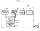
- FIG. 3 is a block diagram for showing an input system including the input part 200 equipped with the rotation angle information estimation-computing unit 120 according to another embodiment of the present invention.
- the input system includes the host device 300 and the input part 200 .
- the input part 200 has acceleration sensors 210 , a rotation angle information estimation-computing portion 220 , a conversion-computing unit 230 , an optimal plane-computing unit 235 , and a transmission unit 240 .
- the acceleration sensors 210 detect and output motion acceleration information. Differently from the embodiment of FIG. 2, there is no need to detect acceleration information just before and after motions.
- the rotation angle information estimation-computing portion 220 includes a separation unit 221 and a computing unit 222 .
- the separation unit 221 inputs motion acceleration information outputted.
- the separation unit 221 separates acceleration information based on the motion of the input part 200 itself and acceleration information based on the gravitational acceleration from the inputted motion acceleration information through a predetermined process.
- LPF low-pass filter
- the acceleration information based on the gravitational acceleration exists in a lower frequency bandwidth than the acceleration information based on motions themselves. Accordingly, in case that a low-pass filter is provided to the separation unit 221 , the acceleration information based on the gravitational acceleration is filtered by the separation unit 221 .
- the computing unit 222 is inputted with acceleration information based on the gravitational acceleration.
- the computing unit 222 calculates motion rotation angle information through Equations 4 and 5 based on acceleration information based on the gravitational acceleration.
- a stationary object has no motions and is affected only by the gravitational force, so that acceleration information based on the gravitational acceleration of the motion acceleration information corresponds to a stationary state.
- Equations 4 and 5 can be applied only in a stationary state. Therefore, Equations 4 and 5 can be applied to the acceleration information based on the gravitational acceleration.
- the computing unit 222 inputs the acceleration information based on the gravitational acceleration, and calculates motion rotation angle information through applications of Equations 4 and 5.
- the calculated motion rotation angle information and the motion acceleration information outputted from the acceleration sensors 210 are transmitted to the conversion-computing unit 230 , and the motion position information for the navigation frame calculated in the conversion-computing unit 230 is transmitted to the host device 300 through the optimal plane-computing unit 135 .
- the present disclosure does not perform any estimation for ⁇ . This is because the ⁇ itself does not affect the trajectory recovery for the input part. Therefore, the values for the ⁇ in the two embodiments are set to zero.
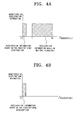
- FIG. 4A is a graph for showing motion acceleration information outputted from the acceleration sensors 110 .
- motion acceleration information outputted from the acceleration sensors is composite information of acceleration information based on the gravitational acceleration and acceleration information based on motions themselves.
- acceleration information based on motions themselves generally exists in a frequency band ranging from 1 Hz to 20 Hz, and acceleration information based on the gravitational acceleration exists in a frequency band near 0 Hz.
- FIG. 4B is a graph for showing acceleration information in case that only the acceleration information based on the gravitation acceleration is separated from the acceleration information of FIG. 4A with the separation unit 221 equipped with a low-pass filter.
- acceleration information in a high-frequency band is not filtered for an output, but only the acceleration information in a low-frequency band is outputted. Therefore, as shown in FIG. 4B, only the acceleration information based on the gravitational acceleration is outputted.
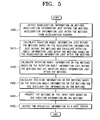
- FIG. 5 is a flow chart for showing a trajectory estimation method based on the input system according to the embodiment of FIG. 2.
- a user takes certain motions with the input part 100 .
- the acceleration sensors 110 in the input part 100 detect and output motion acceleration information based on the motions of the input part 100 (S 400 ).
- the outputted acceleration information consists of pre-motion acceleration information, motion acceleration information, and post-motion acceleration information.
- the outputted pre-motion and post-motion acceleration information is inputted to the rotation angle information estimation-computing portion 120 .
- the first computing unit 121 in the rotation angle information estimation-computing portion 120 applies Equations 4 and 5 to the pre-motion acceleration information and the post-motion acceleration information.
- pre-motion rotation angle information corresponding to the pre-motion acceleration information is calculated
- post-motion rotation angle information corresponding to the post-motion acceleration information is calculated (S 410 ).
- the calculated pre-motion rotation angle information and the post-motion rotation angle information are outputted to the second computing unit 122 .
- the second computing unit 122 applies Equations 6 and 7 to the pre-motion rotation angle information and the post-motion rotation angle information. Accordingly, the motion rotation angle information is calculated (S 420 ).
- the calculated motion rotation angle information is outputted to the conversion-computing unit 130 . Further, the acceleration information outputted from the acceleration sensors 110 is outputted to the conversion-computing unit 130 .
- the conversion-computing unit 130 calculates motion position information for the navigation frame based on the inputted acceleration information and angular velocity information (S 430 ).
- the motion position information for the calculated navigation frame is projected onto an optimal plane by the optimal plane-computing unit 135 (S 440 ).
- the position information projected on the optimal plane is outputted to the host device 300 through the transmission unit 140 (S 450 ).
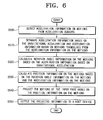
- FIG. 6 is a flow chart for showing a trajectory estimation method for the input system according to the embodiment of FIG. 3.
- a user takes certain motions with the input part 200 .
- the acceleration sensors 210 in the input part 200 outputs motion acceleration information based on the motions of the input part 200 (S 500 ).
- the outputted motion acceleration information consists of acceleration information based on the motions themselves and acceleration information based on the gravitational acceleration.
- the outputted motion acceleration information is inputted to the rotation angle information estimation-computing portion 220 .
- the separation unit 221 in the rotation angle information estimation-computing portion 220 separates the inputted motion acceleration information into the acceleration information based on the motions themselves and the acceleration information based on the gravitational acceleration (S 510 ).
- the acceleration information based on the separated gravitational acceleration is inputted to the rotation angle information estimation-computing portion 220 .
- the computing unit 222 in the rotation angle information estimation-computing portion 220 applies Equations 4 and 5 to the acceleration information based on the gravitational acceleration of the separated acceleration information. Accordingly, motion rotation angle information is calculated (S 520 ).
- the calculated motion rotation angle information is outputted to the conversion-computing unit 230 . Further, the acceleration information outputted from the acceleration sensors 210 is outputted to the conversion-computing unit 230 .
- the conversion-computing unit 230 calculates motion position information for the navigation frame based on the inputted acceleration information and angular velocity information (S 530 ).
- the calculated motion position information for the gravitational frame is projected onto an optimal plane by the optimal plane-computing unit 235 (S 540 ).
- the position information projected on the optimal plane is outputted to the host device 300 through the transmission unit 240 (S 550 ).
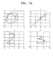
- FIG. 7A illustrates results of certain numbers written by an input apparatus to which the present invention is applied.
- FIG. 7A shows the experimental results for numbers 0 ⁇ 3.
- the one-dotted lines in FIG. 7A indicate numbers written by an input part without angular velocity sensors according to the embodiment of FIG. 2.
- the dotted lines in FIG. 7A indicate numbers written by the input part without angular velocity sensors according to the embodiment of FIG. 3.
- the solid lines indicate numbers directly written on a tablet by a stylus pen.
- the two-dotted lines in FIG. 7A indicate numbers written by an input part with angular velocity sensors.
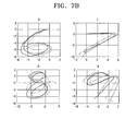
- FIG. 7B illustrates results of other certain numbers written by the input part to which the present invention is applied
- FIG. 7C illustrates results of certain letters written by the input part to which the present invention is applied.
- FIG. 7B shows an experimental result for numbers 6 ⁇ 9
- FIG. 7C shows an experimental result for English letters G, H, I, and J.
- the embodiment presented in FIG. 2 and the embodiment present in FIG. 3 are each structured to perform a predetermined computing process in the input part so that only the position information as final processing result values is transmitted to the host device.
- the above structure is exemplified for the above embodiments, and, for a different embodiment, the structure may be constructed in a different way in order that the input part detects only acceleration information outputted from the acceleration sensors, the detected acceleration information is transmitted to the host device through the transmission unit, and the host device performs the computing process by the rotation angle information estimation-computing portion, the computing process by the conversion-computing unit, and the optimal plane-computing process.
- the structure may be constructed so that the input part detects acceleration information outputted from the acceleration sensors, the rotation angle information estimation-computing portion calculates rotation angle information based on the detected acceleration information, the calculated rotation angle information is transmitted to the host device through the transmission unit, and the host device performs the computing process by the conversion-computing unit and the optimal plane-computing process.
- the input system based on the three-dimensional inertial navigation system and a trajectory estimation method thereof according to the present invention can recover three-dimensional motions in use of only three acceleration sensors without angular velocity sensors, rather than using three acceleration sensors and three angular velocity sensors as in the three-dimensional inertial navigation system. Further, the present invention can input any writings a user desires without limit to a time and place. Accordingly, the input system can be manufactured at a low cost since only three acceleration sensors are used, manufactured light-weight to be convenient in carrying, reduce power consumption, and eliminate the troublesomeness of initial correction work.
Abstract
Description
- This application claims the priority of Korean Patent Application No. 2003-16779, filed on Mar. 13, 2003, in the Korean Intellectual Property Office, the disclosure of which is incorporated herein in its entirety by reference.
- 1. Field of the Invention
- An apparatus consistent with the present invention relates to an input system based on a three-dimensional inertial navigation system and a trajectory estimation method thereof.
- 2. Description of the Related Art
- With progress in the information age, it is more frequently demanded to access and produce information anytime and anywhere, rather than a specific space in computers-equipped environments. Such demands are satisfied with personal portable devices that have been developed and are widely spread, but further research is still required on input systems suitable for such personal portable devices. The specifications required for the input system for personal portable devices include an easy-to-carry and easy-to-input device, thus, there is a demand to develop an input system that is smaller than personal portable devices as well as being easy-to-carry. Further, the nature of the personal portable devices is to facilitate the inputs of new data anytime and anywhere, so that an input system is required which enables users to input such data as they naturally write. In particular, if such an input system can recover writing motions as naturally done on a general plane, a free space, or a sheet of paper so as to enable users to input characters, graphics, gestures, and so on, the input system can be utilized as an excellent input system since it is excellent in the aspect of “universal purpose” and also does not require a particular learning course for use.
- Accordingly, in order to meet the demands on the input system as described above, an input system has been proposed that can input data in space using the concept of a three-dimensional inertial navigation system.
- The three-dimensional inertial navigation system refers to a system that detects three-axis acceleration information and three-axis angular velocity information and applies the detected information to a moving object in order to estimate positions and attitudes of the moving object in the three-dimensional space. The three-dimensional inertial navigation system calculates the attitudes of the object and corrects the acceleration information using an integral value of angular velocity information estimation values, accordingly, calculates velocity information by integrating the corrected acceleration information once, and calculates position information by integrating the corrected acceleration information twice.
- FIG. 1 is a block diagram illustrating an input system using a conventional inertial navigation system.
- The input system using the conventional inertial navigation system includes an
input part 10 and ahost device 20. - The
host device 20 displays an image corresponding to motions based on the motions from theinput part 10. - The
input part 10 includesacceleration sensors 11,angular velocity sensors 12, a rotation angle information-computing unit 13, conversion-computing unit 14, and atransmission unit 15. - The
acceleration sensors 11 generate acceleration information Ab(Abx, Aby, Abz) corresponding to motions based on the motions of theinput part 10, and output the same to the conversion-computing unit 14. The subscript b in the acceleration information denotes acceleration information for a body frame of the input part and the subscripts x, y, and z denote information on x-axis, y-axis, and z-axis. - The
angular velocity sensors 12 generate angular velocity information Wb(Wbx, Wby, Wbz) corresponding to motions based on the motions of theinput part 10, and output the same to the rotation angle information-computing unit 13. The subscript b of the angular velocity information denotes angular velocity information for the body frame of the input part, and the subscripts x, y, and z denote information on x-axis, y-axis, and z-axis. - The rotation angle information-
computing unit 13 inputs angular velocity information from theangular velocity sensors 12. The inputted angular velocity information is converted into rotation angle information χ(Φ, θ, ψ) through a predetermined computing process. The predetermined computing process for the conversion into the rotation angle information is well known to those skilled in the art, so a detailed description on the process will be omitted in the disclosure. - The conversion-
computing unit 14 inputs acceleration information and rotation angle information. The conversion-computing unit 14 calculates the attitudes of theinput part 10 based on the rotation angle information, corrects the acceleration information based on the rotation angle information, calculates velocity information by integrating the corrected acceleration information once, and calculates position information by integrating the corrected acceleration information twice. Such calculations can be performed based onEquations - Prior to explanations of the following Equations, definitions are made for terms used in the Equations as follows:
- A body frame is a frame from which acceleration information and angular velocity information can be detected in correspondence to actual motions of the
input part 10. - A navigation frame is a reference frame for calculating information applicable for a
host device 20 by applying predetermined computing matrices based on a result detected from the body frame. Herein, the coordinate axes for the navigation frame are referred to as X0, Y0, and Z0. - Rotation angle information is as follows: The coordinate axes for the navigation frame and the body frame coincide with each other when there is no rotation at an initial time. When the navigation frame and the body frame coincide with each other at the initial time and the coordinate axes for the body frame are referred to as X 0, Y0, and Z0, Ψ denotes the rotation angle information for the Z0 axis. Further, θ denotes rotation angle information for a Y1 axis indicating an axis after the Y0 axis is rotated as much as Ψ. Φ denotes rotation angle information for a X2 axis indicating an axis after the X0 axis is rotated as much as Ψ and θ, respectively.
- A 3×3 matrix for converting a vector in the body frame into a vector in the navigation frame is as follows:

- In here, the subscripts s, c, and t stand for sine, cosine, and tangent functions, respectively, and the χ denotes rotation angle information in a 3×1 matrix.
- The following is a matrix for calculating the rotation angle information based on the angular velocity information in the body frame:

- Here, the subscripts s, c, and t stand for sine, cosine, and tangent functions, respectively, and the χ denotes the rotation angle information in a 3×1 matrix.
- If the A b denotes the acceleration information in the body frame, the Wb denotes the angular velocity information in the body frame, R denotes a matrix for calculating the rotation angle information based on the angular velocity information in the body frame, G is the gravitational acceleration, and the Cb n denotes a matrix for converting a vector in the body frame into a vector in the navigation frame, position information in the navigation frame is Pn, velocity information in the navigation frame is Vn, and the rotation angle information is χ. These variables can be expressed in
Equations - dPn=Vn [Equation 1]
- dV n =C b n(χ)A b −G [Equation 2]
- dχ=R(χ)Wb [Equation 3]
- Here, P n, Vn, Ab, G, and Wb are a 3×1 matrix, respectively, G is a matrix of [0,0, g]T, and dPn, dVn, and dχ denotes differentiations of Pn, Vn, and χ with respect to time, respectively.
- Accordingly, the acceleration information and the angular velocity information for the body frame outputted from the acceleration sensors and the angular velocity sensors respectively are computed and converted into velocity information and position information for the navigation frame, and a motion image corresponding to motions in the three-dimensional space based on the conversion-computed position information is projected to an optimal projection plane, and then outputted to the
transmission unit 15. - The
transmission unit 15 outputs the projected position information to thehost device 20. - By the above fashion, the motions of the
input part 10 are displayed on thehost device 20. - However, with both the acceleration sensors and the angular velocity sensors used as above, the input part becomes heavy, which brings out a drawback that it is not suitable for portability. Also, there is a drawback in that the price of the angular velocity sensors is so high that the input parts using them become expensive. Further, there exists a drawback in that an amount of power consumption becomes large since the angular velocity sensors and the acceleration sensors have to be all driven. Furthermore, there exists troublesomeness in that a correction job has to be performed in case that the input part is equipped with the angular velocity sensors since the use of the angular velocity sensors inevitably requires an initial correction job.
- Illustrative, non-limiting embodiments of the present invention overcome the above disadvantages and other disadvantages not described above. Also, the present invention is not required to overcome the disadvantages described above, and an illustrative, non-limiting embodiment of the present invention may not overcome any of the problems discussed above.
- An apparatus consistent with the present invention provides an input system based on a three-dimensional inertial navigation system and a trajectory estimation method thereof, capable of recovering motions in the three-dimensional space by using only three acceleration sensors without any angular velocity sensor, that is, without using both three acceleration sensors and three angular velocity sensors as in the three-dimensional inertial navigation system.
- The above aspect is achieved by providing an input system based on a three-dimensional inertial navigation system and having an input part and a host device, which detects motion position information corresponding to three-dimensional motions of the input part and outputs the detected motion position information to the host device. The input system comprises acceleration sensors for outputting acceleration information just before the motions (hereinafter, referred to as pre-motion acceleration information where applicable), acceleration information on the motions (hereinafter, referred to as motion acceleration information where applicable), and acceleration information just after the motions (hereinafter, referred to as post-motion acceleration information where applicable); a rotation angle information estimation-computing portion for estimating rotation angle information Φ, θ, and Ψ on the motions (hereinafter, referred to as motion rotation angle information where applicable) through a predetermined computing process based on the outputted pre-motion acceleration information and post-motion acceleration information; a conversion-computing unit for calculating the motion position information based on the estimated motion rotation angle information and the outputted motion acceleration information; and an optimal plane-computing unit for projecting the motion position information onto an optimal plane.
- The rotation angle information estimation-computing portion includes a first computing unit for calculating rotation angle information Φ1, θ1, and Ψ1 just before the motions (hereinafter, referred to as pre-motion rotation angle information where applicable) and rotation angle information Φ2, θ2, and Ψ2 just after the motions (hereinafter, referred to as post-motion rotation angle information where applicable) through a predetermined computing process based on the outputted pre-motion acceleration information and post-motion acceleration information; and a second computing unit for calculating the motion rotation angle information through a predetermined computing process based on the calculated pre-motion rotation angle information and post-motion rotation angle information.
- Preferably, in the first computing unit, the pre-motion rotation angle information Φ1 and the post-motion rotation angle information Φ2 become

- and

- respectively, and, here, if coordinate axes of a body frame of the input part are denoted as X, Y, and Z, A by1 and Aby2 denote the pre-motion acceleration information and the post-motion acceleration information for the Y axis respectively, and Abz1 and Abz2 denote the pre-motion acceleration information and the post-motion acceleration information for the Z axis respectively, and, if coordinate axes for the navigation frame are denoted as X0, Y0, and Z0, Ψ1 and Ψ2 denote the pre-motion rotation angle information and the post-motion rotation angle information for the Z0 axis, and θ1 denotes the pre-motion rotation angle information for a Y1 axis indicating an axis after the Y0 axis is rotated as much as Ψ1, θ2 denotes the post-motion rotation angle information for Y1 axis indicating an axis after the Y0 axis is rotated as much as Ψ2, Φ1 denotes the pre-motion rotation angle information for the X2 indicating an axis after the X0 axis is rotated as much as Ψ1 and θ1, respectively, and Φ2 denotes the pre-motion rotation angle information for the X2 axis indicating an axis after the X0 is rotated as much as Ψ2 and θ2, respectively.
- Preferably, in the first computing unit, the pre-motion rotation angle information θ1 and the post-motion rotation angle information θ2 become

- and

- respectively, and, here, if coordinate axes of a body frame of the input part are denoted as X, Y, and Z, A bx1 and Abx2 denote the pre-motion acceleration information and the post-motion acceleration information for the X axis respectively, and Aby1 and Aby2 denote the pre-motion acceleration information and the post-motion acceleration information for the Y axis respectively, and Abz1 and Abz2 denote the pre-motion acceleration information and the post-motion acceleration information for the Z axis respectively, and, if coordinate axes for the navigation frame are denoted as X0, Y0, and Z0, Ψ1 and Ψ2 denote the pre-motion rotation angle information and the post-motion rotation angle information for the Z0 axis, and θ1 denotes the pre-motion rotation angle information for a Y1 axis indicating an axis after the Y0 axis is rotated as much as Ψ1, and θ2 denotes the post-motion rotation angle information for Y1 axis indicating an axis after the Y0 axis is rotated as much as Ψ2.
- Preferably, in the second computing unit, the motion rotation angle information d) becomes Φ(t)=a*t+b, and, here, if t 1 denotes time just before the motions, t2 denotes time just after the motions, a denotes [Φ(t2)−(t1)]/(t2−t1), b denotes−a*t, +Φ(t1), and coordinate axes for the navigation frame are denoted as X0, Y0, and Z0, the Ψ denotes the rotation angle information for the Z0 axis, the θ denotes the rotation angle information for the Y1 axis indicating an axis after the Y0 axis is rotated as much as Ψ, and the Φ denotes the rotation angle information for the X2 axis indicating an axis after the X0 axis is rotated as much as Ψ and θ, respectively.
- Preferably, in the second computing unit, the motion rotation angle information θ becomes θ(t)=c*t+d, and, here, if t 1 denotes time just before the motions, t2 denotes time just after the motions, c denotes [θ(t2)−θ(t1)]/(t2−t1), d denotes−c*t1+θ(t1), and coordinate axes are denoted as X0, Y0, and Z0, the Ψ denotes the rotation angle information for the Z0 axis and the 0 denotes the rotation angle information for the Y1 axis indicating an axis after the Y0 axis is rotated as much as Ψ.
- Further, the above object is achieved by providing the input system based on the three-dimensional inertial navigation system according to the present invention and having an input part and a host device, which detects motion position information corresponding to three-dimensional motions of the input part and outputs the detected motion position information to the host device. The input system comprises acceleration sensors for outputting motion acceleration information; a rotation angle information estimation-computing portion for estimating motion rotation angle information Φ, θ, and Ψ based on acceleration information based on the gravitational acceleration separated from the outputted motion acceleration information; a conversion-computing unit for calculating motion position information based on the estimated motion rotation angle information and the outputted motion acceleration information; and an optimal plane-computing unit for projecting the motion position information onto an optimal plane.
- The rotation angle information estimation-computing portion includes a separation unit for separating acceleration information based on the motions of the input part itself and acceleration information based on the gravitational acceleration from the outputted motion acceleration information based on a predetermined process; and a computing unit for calculating the motion rotation angle information through the predetermined computing process based on the acceleration information based on the separated gravitational acceleration.
- Preferably, but not necessarily, the predetermined process for separating the acceleration information based on the gravitational acceleration from the motion acceleration information is to pass the motion acceleration information through a low-pass filter.
- Preferably, but not necessarily, in the computing unit, the motion rotation angle information Φ becomes

- and, here, if coordinate axes of a body frame of the input part are denoted as X, Y, and Z, A by denotes acceleration information for the Y axis and Abz denotes acceleration information for the Z axis, and, if coordinate axes for a navigation frame are denoted as X0, Y0, and Z0, Ψ denotes rotation angle information for the Z0 axis, θ denotes rotation angle information for a Y1 axis indicating an axis after the Y0 axis is rotated as much as Ψ, and Φ denotes rotation angle information for an X2 indicating an axis after the X0 is rotated as much as Ψ and θ, respectively.
- Preferably, but not necessarily, in the computing unit, the motion rotation angle information θ becomes

- and, here, if coordinate axes for the body frame are denoted as X, Y, and Z, A bx denotes acceleration information for the X axis, Aby denotes acceleration information for the Y axis, Abz denotes acceleration information for the Z axis, and coordinate axes for the navigation frame are denoted as X0, Y0, and Z0, Ψ denotes rotation angle information for the Z0 axis and θ denotes rotation angle information for a Y1 axis indicating an axis after the Y0 is rotated as much as Ψ.
- Further, the above object is achieved by providing a trajectory estimation method for an input system based on a three-dimensional inertial navigation system and having an input part and a host device according to the present invention, which detects motion position information corresponding to three-dimensional motions of the input part and outputs the detected motion position information to the host device. The method comprises steps of (a) outputting motion acceleration information, pre-motion acceleration information, and post-motion acceleration information just after the motions; (b) estimating motion rotation angle information Φ, θ, and Ψ through a predetermined computing process based on the outputted pre-motion acceleration information and post-motion acceleration information; (c) calculating the motion position information based on the estimated motion rotation angle information and the outputted motion acceleration information; and (d) projecting the motion position information onto an optimal plane.
- The step (b) includes steps of (b1) calculating pre-motion rotation angle information Φ1, θ1, and Ψ1 and post-motion rotation angle information Φ2, θ2, and Ψ2 through a predetermined computing process based on the outputted pre-motion acceleration information and post-motion acceleration information; and (b2) calculating the motion rotation angle information through a predetermined computing process based on the calculated pre-motion rotation angle information and post-motion rotation angle information.
- Preferably, but not necessarily, in the step (b1), the pre-motion rotation angle information Φ1 and the post-motion rotation angle information Φ2 become

- respectively, and, here, if coordinate axes of a body frame of the input part are denoted as X, Y, and Z, A by1 and Aby2 denote the pre-motion acceleration information and the post-motion acceleration information for the Y axis respectively, and Abz1 and Abz2 denote the pre-motion acceleration information and the post-motion acceleration information for the Z axis respectively, and, if coordinate axes for the navigation frame are denoted as X0, Y0, and Z0, Ψ1 and Ψ2 denote the pre-motion rotation angle information and the post-motion rotation angle information for the Z0 axis, and θ1 denotes the pre-motion rotation angle information for a Y1 axis indicating an axis after the Y0 axis is rotated as much as Ψ1, θ2 denotes the post-motion rotation angle information for Y1 axis indicating an axis after the Y0 axis is rotated as much as Ψ2, Φ1 denotes the pre-motion rotation angle information for the X2 indicating an axis after the X0 axis is rotated as much as Ψ1 and θ1, respectively, and Φ2 denotes the pre-motion rotation angle information for the X2 axis indicating an axis after the X0 is rotated as much as Ψ1, θ2, respectively.
- Preferably, but not necessarily, in the step (b1), the pre-motion rotation angle information θ1 and the post-motion rotation angle information θ2 become

- respectively, and, here, if coordinate axes of a body frame of the input part are denoted as X, Y, and Z, A bx1 and Abx2 denote the pre-motion acceleration information and the post-motion acceleration information for the X axis respectively, and Aby1 and Aby2 denote the pre-motion acceleration information and the post-motion acceleration information for the Y axis respectively, and Abz1 and Abz2 denote the pre-motion acceleration information and the post-motion acceleration information for the Z axis respectively, and, if coordinate axes for the navigation frame are denoted as X0, Y0, and Z0, Ψ1 and Ψ2 denote the pre-motion rotation angle information and the post-motion rotation angle information for the Z0 axis, and θ1 denotes the pre-motion rotation angle information for a Y1 axis indicating an axis after the Y0 axis is rotated as much as Ψ1, and θ2 denotes the post-motion rotation angle information for Y1 axis indicating an axis after the Y0 axis is rotated as much as Ψ2.
- Preferably, but not necessarily, in the step (b2), the motion rotation angle information Φ becomes Φ(t)=a*t+b and, here, if t 1 denotes time just before the motions, t2 denotes time just after the motions, a denotes [Φ(t2)−Φ(t1)]/(t2−t1), b denotes −a*t, +Φ(t1), and coordinate axes are denoted as X0, Y0, and Z0, the Ψ denotes the rotation angle information for the Z0 axis, the θ denotes the rotation angle information for the Y1 axis indicating an axis after the Y0 axis is rotated as much as Ψ, and the Φ denotes the rotation angle information for the X2 axis indicating an axis after the X0 axis is rotated as much as Ψ and θ, respectively.
- Preferably, but not necessarily, in the step (b2), the motion rotation angle information θ becomes θ(t)=c*t+d and, here, if t 1 denotes time just before the motions, t2 denotes time just after the motions, c denotes [θ(t2)−θ(t1)]/(t2−t1), d denotes −c*t, +θ(t1), and coordinate axes are denoted as X0, Y0, and Z0, the Ψ denotes the rotation angle information for the Z0 axis and the 0 denotes the rotation angle information for the Y1 axis indicating an axis after the Y0 axis is rotated as much as Ψ.
- Further, the above object is achieved by providing a trajectory estimation method for an input system based on a three-dimensional inertial navigation system and having an input part and a host device, which detects motion position information corresponding to motions of the input part based on three-dimensional motions of the input part and outputs the detected motion position information to the host device. The method comprises steps of: (a) outputting motion acceleration information; (b) estimating motion rotation angle information Φ, θ, and Ψ based on acceleration information based on the gravitational acceleration separated from the outputted motion acceleration information; (c) calculating motion position information based on the estimated motion rotation angle information and the outputted motion acceleration information; and (d) projecting the motion position information onto an optimal plane.
- The step (b) includes steps of (b1) separating acceleration information based on the motions of the input part itself and acceleration information based on the gravitational acceleration from the outputted motion acceleration information based on a predetermined process; and (b2) calculating the motion rotation angle information through the predetermined computing process based on the acceleration information based on the separated gravitational acceleration.
- Preferably, but not necessarily, the predetermined process in the step (b1) is to pass the motion acceleration information through a low-pass filter.
- Preferably, but not necessarily, the motion
rotation angle information 4 in the step (b2) becomes
- and, here, if coordinate axes of a body frame of the input part are denoted as X, Y, and Z, A by denotes acceleration information for the Y axis and Abz denotes acceleration information for the Z axis, and, if coordinate axes for a navigation frame are denoted as X0, Y0, and Z0, Ψ denotes rotation angle information for the Z0 axis, θ denotes rotation angle information for a Y1 axis indicating an axis after the Y0 axis is rotated as much as Ψ, and Φ denotes rotation angle information for an X2 indicating an axis after the X0 is rotated as much as Ψ and 0, respectively.
- Preferably, but not necessarily, the motion rotation angle information θ in the step (b2) becomes

- and, here, if coordinate axes for the body frame are denoted as X, Y, and Z, A bx denotes acceleration information for the X axis, Aby denotes acceleration information for the Y axis, Abz denotes acceleration information for the Z axis, and coordinate axes for the navigation frame are denoted as X0, Y0, and Z0, Ψ denotes rotation angle information for the Z0 axis and θ denotes rotation angle information for a Y1 axis indicating an axis after the Y0 is as much as Ψ.
- Accordingly, the present invention can recover the three-dimensional motions by using only the three acceleration sensors without the angular velocity sensors in the three-dimensional inertial navigation system.
- The features and advantages of the present invention will become more apparent by describing in detail exemplary embodiments thereof with reference to the following drawings in which like reference numerals refer to like elements, and wherein:
- FIG. 1 is a block diagram for showing an input system using a conventional inertial navigation system;
- FIG. 2 is a block diagram for showing an input system including an input part equipped with a rotation angle information estimation-computing portion according to an embodiment of the present invention;
- FIG. 3 is a block diagram for showing an input system including an input part equipped with a rotation angle information estimation-computing portion according to another embodiment of the present invention;
- FIG. 4A is a graph for showing acceleration information on motions outputted from acceleration sensors;
- FIG. 4B is a graph for showing acceleration information in case that only the acceleration information based on the gravitational acceleration is separated from the acceleration information of FIG. 4A when a low-pass filter is provided in a separation unit;
- FIG. 5 is a flow chart for showing a trajectory estimation method for an input system of FIG. 2 according to an embodiment of the present invention;
- FIG. 6 is a flow chart for showing a trajectory estimation method for an input system of FIG. 3 according to another embodiment of the present invention;
- FIG. 7A is a view for showing results of certain numbers written by an input system to which the present invention is applied;
- FIG. 7B is a view for showing results of other certain numbers written by an input system to which the present invention is applied; and
- FIG. 7C is a view for showing results of certain letters written by an input system to which the present invention is applied.
- Hereinafter, an input system according to an exemplary embodiment of the present invention is described in detail with reference to the accompanying drawings.
- FIG. 2 is a block diagram for showing an input system including an
input part 100 equipped with a rotation angle information estimation-computing portion 120 according to an embodiment of the present invention. - The input system according to the present invention has the
input part 100 and ahost device 300. - The
input part 100 includesacceleration sensors 110, the rotation angle information estimation-computing portion 120, a conversion-computing unit 130, an optimal plane-computing unit 135 and atransmission unit 140. - The
acceleration sensors 110 are provided for three X, Y1 and Z axes of a body frame of theinput part 100 according to three x, y, and z axes to be based on motions of theinput part 100. Theacceleration sensors 110 detect and output acceleration information on motions (hereinafter, referred to as motion acceleration information where applicable), acceleration information just before the motions (hereinafter, referred to as pre-motion acceleration information where applicable), and acceleration information just after the motions (hereinafter, referred to as post-motion acceleration information where applicable), respectively. It is preferable for the three acceleration sensors to be provided in theinput part 100, but it is possible to provide two acceleration sensors that can detect acceleration information on two axes. - Definitions for the acceleration information on motions, acceleration information just before the motions, and acceleration information just after the motions, are as follows.
- In order to do trajectory estimations for the
input part 100 according to an embodiment of FIG. 2, an assumption is necessary that theinput part 100 has to remain still just before and after intended motions to be taken by theinput part 100. Accordingly, theacceleration sensors 110 according to the present invention can detect acceleration information just before and after intended motions to be taken by theinput part 100. The pre-motion acceleration information refers to acceleration information just before intended motions. Further, the post-motion acceleration information refers to acceleration information just after intended motions. Motion acceleration information refers to acceleration information based on intended motions to be taken by a user. - The rotation angle information estimation-
computing portion 120 computes and estimates rotation angle information based on pre-motion acceleration information and post-motion acceleration information outputted from theacceleration sensors 110. - The rotation angle information estimation-
computing portion 120 according to an embodiment of the present invention includes afirst computing unit 121 and asecond computing unit 122. - The first computing-
unit 121 inputs pre-motion acceleration information and post-motion acceleration information on theinput part 100 from theacceleration sensors 110. - The
first computing unit 121 computes Φ and θ of rotation angle information just before motions through a predetermined computing process based on pre-motion acceleration information. Here, the rotation angle information just before motions is pre-motion rotation angle information corresponding to the pre-motion acceleration information. - The
first computing unit 121 computes Φ and θ of rotation angle information just after motions through a predetermined computing process based on post-motion acceleration information. In here, the rotation angle information just after motions is post-motion rotation angle information corresponding to the post-motion acceleration information. - In case that coordinate axes for the body frame are denoted as X, Y, and Z, acceleration information for the X axis of the body frame is denoted as A bx, acceleration information for the Y axis of the body frame as Aby, acceleration information for the Z axis of the body frame as Abz, rotation angle information for a Z0 axis as ψ, and rotation angle information for a Y1 axis, indicating an axis after a Y0 axis is rotated as much as Ψ, as θ,
Equation 4 expresses rotation angle information Φ for a X2 axis indicating an axis after the X0 axis is rotated as much as Ψ and θ, respectively.
- In case that coordinate axes for the body frame are denoted as X, Y, and Z, acceleration information for the X axis of the body frame is denoted as A bx, acceleration information for the Y axis of the body frame as Aby, acceleration information for the Z axis of the body frame as Abz, and rotation angle information for a Z0 axis as Ψ, rotation angle information θ for Y1 axis indicating an axis after a Y0 axis is rotated as much as Ψ can be expressed in
Equation 5 as follows:
- Equations 4 and 5 are formulae by which the Φ and θ of rotation angle information can be respectively calculated from acceleration information at the state of no motion.
- The
second computing unit 122 inputs the Φ and θ of pre-motion rotation angle information computed from thefirst computing unit 121. - The
second computing unit 122 inputs the Φ and θ of post-motion rotation angle information computed from thefirst computing unit 121. - The
second computing unit 122 computes the motion rotation angle information Φ through a predetermined computing process based on the Φ of the inputted pre-motion rotation angle information and the Φ of the inputted post-motion rotation angle information. - The
second computing unit 122 computes the motion rotation angle information θ through a predetermined computing process based on the θ of the inputted pre-motion rotation angle information and the θ of the inputted post-motion rotation angle information. - If the time just before a motion is denoted as t 1, the time just after a motion as t2, [Φ(t2)−Φ(t1)]/(t2−t1) as a, and −a*t1+Φ(t1) as b, the Φ(t) of the motion rotation angle information can be expressed in
Equation 6 as follows: - Φ(t)=a*t+b [Equation 6]
- Further, if the time just before a motion is denoted as t 1, the time just after a motion as t2, [θ(t2)−θ(t1)]/(t2−t1) as c, and −c*t1+θ(t1) as d, the θ(t) of the motion rotation angle information can be expressed in
Equation 7 as follows: - θ(t)=C*t+d [Equation 7]
- The conversion-
computing unit 130 inputs motion acceleration information from theacceleration sensors 110, and inputs motion rotation angle information estimated from the rotation angle information estimating-computing portion 120. Based on the inputted motion acceleration information and motion rotation angle information, motion velocity information Vn and motion position information Pn for the navigation frame are calculated as in the conversion-computing unit of FIG. 1. - The optimal plane-
computing unit 135 projects onto a virtual two-dimensional optimal plane the motion position information outputted from the conversion-computing unit 130 to obtain coordinate values. - The
transmission unit 140 outputs to thehost device 300 the projected position information outputted from the optimal plane-computing unit 135. Thetransmission unit 140 can be constructed with a wired communication module, but, preferably, with a wireless communication module such as Bluetooth®. - The
host device 300 displays position information corresponding to motions based on the motions of theinput part 100. Thehost device 300 is preferably a personal portable device. - FIG. 3 is a block diagram for showing an input system including the
input part 200 equipped with the rotation angle information estimation-computing unit 120 according to another embodiment of the present invention. - As described in FIG. 2, the input system according to the present invention includes the
host device 300 and theinput part 200. - The
input part 200 hasacceleration sensors 210, a rotation angle information estimation-computing portion 220, a conversion-computing unit 230, an optimal plane-computing unit 235, and atransmission unit 240. - The description on the conversion-
computing unit 230 and thetransmission unit 240 is the same as in FIG. 2. - Accordingly, hereinafter, a description is made only of the
acceleration sensors 210 and the rotation angle information estimation-computing portion 220. - The
acceleration sensors 210 according to the present embodiment detect and output motion acceleration information. Differently from the embodiment of FIG. 2, there is no need to detect acceleration information just before and after motions. - The rotation angle information estimation-
computing portion 220 according to the present embodiment includes aseparation unit 221 and acomputing unit 222. - The
separation unit 221 inputs motion acceleration information outputted. Thus, theseparation unit 221 separates acceleration information based on the motion of theinput part 200 itself and acceleration information based on the gravitational acceleration from the inputted motion acceleration information through a predetermined process. - For the predetermined process, it is preferable to provide a low-pass filter (LPF) to the
separation unit 221. - In general, the acceleration information based on the gravitational acceleration exists in a lower frequency bandwidth than the acceleration information based on motions themselves. Accordingly, in case that a low-pass filter is provided to the
separation unit 221, the acceleration information based on the gravitational acceleration is filtered by theseparation unit 221. - The
computing unit 222 is inputted with acceleration information based on the gravitational acceleration. - The
computing unit 222 calculates motion rotation angle information throughEquations - In general, a stationary object has no motions and is affected only by the gravitational force, so that acceleration information based on the gravitational acceleration of the motion acceleration information corresponds to a stationary state.
- Further, as described above,
Equations Equations computing unit 222 inputs the acceleration information based on the gravitational acceleration, and calculates motion rotation angle information through applications ofEquations - The calculated motion rotation angle information and the motion acceleration information outputted from the
acceleration sensors 210 are transmitted to the conversion-computing unit 230, and the motion position information for the navigation frame calculated in the conversion-computing unit 230 is transmitted to thehost device 300 through the optimal plane-computing unit 135. - However, the present disclosure does not perform any estimation for ψ. This is because the ψ itself does not affect the trajectory recovery for the input part. Therefore, the values for the ψ in the two embodiments are set to zero.
- FIG. 4A is a graph for showing motion acceleration information outputted from the
acceleration sensors 110. - In general, motion acceleration information outputted from the acceleration sensors is composite information of acceleration information based on the gravitational acceleration and acceleration information based on motions themselves. As shown in FIG. 4A, acceleration information based on motions themselves generally exists in a frequency band ranging from 1 Hz to 20 Hz, and acceleration information based on the gravitational acceleration exists in a frequency band near 0 Hz.
- FIG. 4B is a graph for showing acceleration information in case that only the acceleration information based on the gravitation acceleration is separated from the acceleration information of FIG. 4A with the
separation unit 221 equipped with a low-pass filter. - In case that the
separation unit 221 has a low-pass filter, acceleration information in a high-frequency band is not filtered for an output, but only the acceleration information in a low-frequency band is outputted. Therefore, as shown in FIG. 4B, only the acceleration information based on the gravitational acceleration is outputted. - FIG. 5 is a flow chart for showing a trajectory estimation method based on the input system according to the embodiment of FIG. 2.
- Descriptions are made of the method with reference to FIG. 2 and FIG. 5. First, a user takes certain motions with the
input part 100. Theacceleration sensors 110 in theinput part 100 detect and output motion acceleration information based on the motions of the input part 100 (S400). - The outputted acceleration information consists of pre-motion acceleration information, motion acceleration information, and post-motion acceleration information. The outputted pre-motion and post-motion acceleration information is inputted to the rotation angle information estimation-
computing portion 120. Thefirst computing unit 121 in the rotation angle information estimation-computing portion 120 appliesEquations - The calculated pre-motion rotation angle information and the post-motion rotation angle information are outputted to the
second computing unit 122. Thesecond computing unit 122 appliesEquations - The calculated motion rotation angle information is outputted to the conversion-
computing unit 130. Further, the acceleration information outputted from theacceleration sensors 110 is outputted to the conversion-computing unit 130. The conversion-computing unit 130 calculates motion position information for the navigation frame based on the inputted acceleration information and angular velocity information (S430). - The motion position information for the calculated navigation frame is projected onto an optimal plane by the optimal plane-computing unit 135 (S440). The position information projected on the optimal plane is outputted to the
host device 300 through the transmission unit 140 (S450). - FIG. 6 is a flow chart for showing a trajectory estimation method for the input system according to the embodiment of FIG. 3.
- Descriptions are made with reference to FIG. 3 and FIG. 6. First, a user takes certain motions with the
input part 200. Theacceleration sensors 210 in theinput part 200 outputs motion acceleration information based on the motions of the input part 200 (S500). - The outputted motion acceleration information consists of acceleration information based on the motions themselves and acceleration information based on the gravitational acceleration. The outputted motion acceleration information is inputted to the rotation angle information estimation-
computing portion 220. Theseparation unit 221 in the rotation angle information estimation-computing portion 220 separates the inputted motion acceleration information into the acceleration information based on the motions themselves and the acceleration information based on the gravitational acceleration (S510). - The acceleration information based on the separated gravitational acceleration is inputted to the rotation angle information estimation-
computing portion 220. Thecomputing unit 222 in the rotation angle information estimation-computing portion 220 appliesEquations - The calculated motion rotation angle information is outputted to the conversion-
computing unit 230. Further, the acceleration information outputted from theacceleration sensors 210 is outputted to the conversion-computing unit 230. The conversion-computing unit 230 calculates motion position information for the navigation frame based on the inputted acceleration information and angular velocity information (S530). - The calculated motion position information for the gravitational frame is projected onto an optimal plane by the optimal plane-computing unit 235 (S540). The position information projected on the optimal plane is outputted to the
host device 300 through the transmission unit 240 (S550). - FIG. 7A illustrates results of certain numbers written by an input apparatus to which the present invention is applied.
- FIG. 7A shows the experimental results for
numbers 0˜3. - The one-dotted lines in FIG. 7A indicate numbers written by an input part without angular velocity sensors according to the embodiment of FIG. 2. The dotted lines in FIG. 7A indicate numbers written by the input part without angular velocity sensors according to the embodiment of FIG. 3. The solid lines indicate numbers directly written on a tablet by a stylus pen. The two-dotted lines in FIG. 7A indicate numbers written by an input part with angular velocity sensors.
- FIG. 7B illustrates results of other certain numbers written by the input part to which the present invention is applied, and FIG. 7C illustrates results of certain letters written by the input part to which the present invention is applied.
- FIG. 7B shows an experimental result for
numbers 6˜9, and FIG. 7C shows an experimental result for English letters G, H, I, and J. - The descriptions on the one-dotted lines, dotted lines, solid lines, and two-dotted lines are the same as in FIG. 7A.
- As shown in FIG. 7A, FIG. 7B, and FIG. 7C, the numbers and letters that are written by the input part with angular velocity sensors and directly written on the tablet are nearly the same as those that are written by the input parts according to the embodiments of the present invention, and, further, it can be seen that the degrees to which the writings can be recognized are nearly the same
- However, the embodiment presented in FIG. 2 and the embodiment present in FIG. 3 are each structured to perform a predetermined computing process in the input part so that only the position information as final processing result values is transmitted to the host device.
- However, the above structure is exemplified for the above embodiments, and, for a different embodiment, the structure may be constructed in a different way in order that the input part detects only acceleration information outputted from the acceleration sensors, the detected acceleration information is transmitted to the host device through the transmission unit, and the host device performs the computing process by the rotation angle information estimation-computing portion, the computing process by the conversion-computing unit, and the optimal plane-computing process.
- Further, for another embodiment, the structure may be constructed so that the input part detects acceleration information outputted from the acceleration sensors, the rotation angle information estimation-computing portion calculates rotation angle information based on the detected acceleration information, the calculated rotation angle information is transmitted to the host device through the transmission unit, and the host device performs the computing process by the conversion-computing unit and the optimal plane-computing process.
- The input system based on the three-dimensional inertial navigation system and a trajectory estimation method thereof according to the present invention can recover three-dimensional motions in use of only three acceleration sensors without angular velocity sensors, rather than using three acceleration sensors and three angular velocity sensors as in the three-dimensional inertial navigation system. Further, the present invention can input any writings a user desires without limit to a time and place. Accordingly, the input system can be manufactured at a low cost since only three acceleration sensors are used, manufactured light-weight to be convenient in carrying, reduce power consumption, and eliminate the troublesomeness of initial correction work.
- While the invention has been shown and described with reference to exemplary embodiments thereof for illustrative purposes, it will be understood by those skilled in the art that various changes in form and details may be made therein without departing from the spirit and scope of the invention as defined by the appended claims.
Claims (22)


Applications Claiming Priority (2)
| Application Number | Priority Date | Filing Date | Title |
|---|---|---|---|
| KR10-2003-0016779A KR100518832B1 (en) | 2003-03-18 | 2003-03-18 | a input system based on three dimensional Inertial Navigation System and method for trajectory estimation thereof |
| KR10-2003-0016779 | 2003-03-18 |
Publications (2)
| Publication Number | Publication Date |
|---|---|
| US20040236500A1 true US20040236500A1 (en) | 2004-11-25 |
| US7353112B2 US7353112B2 (en) | 2008-04-01 |
Family
ID=32822737
Family Applications (1)
| Application Number | Title | Priority Date | Filing Date |
|---|---|---|---|
| US10/802,056 Expired - Fee Related US7353112B2 (en) | 2003-03-18 | 2004-03-17 | Input system based on a three-dimensional inertial navigation system and trajectory estimation method thereof |
Country Status (5)
| Country | Link |
|---|---|
| US (1) | US7353112B2 (en) |
| EP (1) | EP1460382B1 (en) |
| JP (1) | JP3884442B2 (en) |
| KR (1) | KR100518832B1 (en) |
| DE (1) | DE602004027182D1 (en) |
Cited By (32)
| Publication number | Priority date | Publication date | Assignee | Title |
|---|---|---|---|---|
| US20060258194A1 (en) * | 2005-05-12 | 2006-11-16 | Samsung Electronics Co., Ltd. | Portable terminal having motion detection function and motion detection method therefor |
| US20070091292A1 (en) * | 2005-09-15 | 2007-04-26 | Samsung Electronics Co., Ltd. | System, medium, and method controlling operation according to instructional movement |
| US20080091350A1 (en) * | 2006-10-17 | 2008-04-17 | Smith Stephen F | Triply redundant integrated navigation and asset visibility system |
| US20080260250A1 (en) * | 2001-04-09 | 2008-10-23 | I.C. + Technologies Ltd. | Apparatus and methods for hand motion detection and handwriting recognition generally |
| US7647195B1 (en) * | 2006-07-11 | 2010-01-12 | Dp Technologies, Inc. | Method and apparatus for a virtual accelerometer system |
| US20100103980A1 (en) * | 2006-10-17 | 2010-04-29 | Smith Stephen F | Robust Low-Frequency Spread-Spectrum Navigation System |
| US7753861B1 (en) | 2007-04-04 | 2010-07-13 | Dp Technologies, Inc. | Chest strap having human activity monitoring device |
| CN101788851A (en) * | 2010-02-22 | 2010-07-28 | 中国电信股份有限公司 | Method and system for simulating motion of handle |
| US7788059B1 (en) | 2006-11-21 | 2010-08-31 | Dp Technologies, Inc. | Rotational insensitivity using gravity-based adjustments |
| US20110006977A1 (en) * | 2009-07-07 | 2011-01-13 | Microsoft Corporation | System and method for converting gestures into digital graffiti |
| US8187182B2 (en) | 2008-08-29 | 2012-05-29 | Dp Technologies, Inc. | Sensor fusion for activity identification |
| US8285344B2 (en) | 2008-05-21 | 2012-10-09 | DP Technlogies, Inc. | Method and apparatus for adjusting audio for a user environment |
| US20130035890A1 (en) * | 2011-08-04 | 2013-02-07 | Wang Jeen-Shing | Moving trajectory calibration method and moving trajectory generation method |
| US8384487B2 (en) | 2011-04-08 | 2013-02-26 | Ut-Battelle, Llc | Orthogonally referenced integrated ensemble for navigation and timing |
| US8555282B1 (en) | 2007-07-27 | 2013-10-08 | Dp Technologies, Inc. | Optimizing preemptive operating system with motion sensing |
| US8620353B1 (en) | 2007-01-26 | 2013-12-31 | Dp Technologies, Inc. | Automatic sharing and publication of multimedia from a mobile device |
| US8712723B1 (en) | 2006-12-22 | 2014-04-29 | Dp Technologies, Inc. | Human activity monitoring device |
| CN103808322A (en) * | 2014-03-04 | 2014-05-21 | 韩涛 | Compound type six degrees of freedom input method and system in inertia measurement LED (light-emitting diode) detection |
| US20140253443A1 (en) * | 2013-03-08 | 2014-09-11 | Microsoft Corporation | Using portable electronic devices for user input |
| US8872646B2 (en) | 2008-10-08 | 2014-10-28 | Dp Technologies, Inc. | Method and system for waking up a device due to motion |
| US8902154B1 (en) | 2006-07-11 | 2014-12-02 | Dp Technologies, Inc. | Method and apparatus for utilizing motion user interface |
| US8949070B1 (en) | 2007-02-08 | 2015-02-03 | Dp Technologies, Inc. | Human activity monitoring device with activity identification |
| US8996332B2 (en) | 2008-06-24 | 2015-03-31 | Dp Technologies, Inc. | Program setting adjustments based on activity identification |
| US9068844B2 (en) | 2010-01-08 | 2015-06-30 | Dp Technologies, Inc. | Method and apparatus for an integrated personal navigation system |
| US20160011010A1 (en) * | 2014-07-10 | 2016-01-14 | Micronas Gmbh | Apparatus And Method For Contactless Measurement Of An Angle |
| US9374659B1 (en) | 2011-09-13 | 2016-06-21 | Dp Technologies, Inc. | Method and apparatus to utilize location data to enhance safety |
| US9390229B1 (en) | 2006-04-26 | 2016-07-12 | Dp Technologies, Inc. | Method and apparatus for a health phone |
| US9529437B2 (en) | 2009-05-26 | 2016-12-27 | Dp Technologies, Inc. | Method and apparatus for a motion state aware device |
| US9703385B2 (en) | 2008-06-20 | 2017-07-11 | Microsoft Technology Licensing, Llc | Data services based on gesture and location information of device |
| US10057724B2 (en) | 2008-06-19 | 2018-08-21 | Microsoft Technology Licensing, Llc | Predictive services for devices supporting dynamic direction information |
| US10780563B2 (en) | 2016-10-07 | 2020-09-22 | Makita Corporation | Electric power tool and method of controlling rotational speed of motor in electric power tool |
| US10953532B2 (en) * | 2016-10-07 | 2021-03-23 | Makita Corporation | Electric power tool configured to detect twisted motion |
Families Citing this family (6)
| Publication number | Priority date | Publication date | Assignee | Title |
|---|---|---|---|---|
| KR20090001721A (en) * | 2007-05-14 | 2009-01-09 | 팅크웨어(주) | Method for correcting map matching and navigation system implementing the method |
| KR100868241B1 (en) | 2008-05-29 | 2008-11-11 | 로봇기술(주) | Interior position tracking apparatus using acceleration sensor |
| CN103019414B (en) * | 2012-11-02 | 2015-08-05 | 浙江大学 | Based on the person's handwriting method of estimation of the electronic handwriting pen of IMU |
| CN105698765B (en) * | 2016-02-22 | 2018-09-18 | 天津大学 | Object pose method under double IMU monocular visions measurement in a closed series noninertial systems |
| CN107255475B (en) * | 2017-07-03 | 2020-09-25 | 中国科学院光电技术研究所 | Symmetric structure accelerometer north finder and dynamic differential north finding method |
| KR102062263B1 (en) * | 2018-05-30 | 2020-01-03 | 국방과학연구소 | Apparatus for generating a trajectory of a vehicle and method thereof |
Citations (7)
| Publication number | Priority date | Publication date | Assignee | Title |
|---|---|---|---|---|
| US3545266A (en) * | 1964-02-17 | 1970-12-08 | Thomas L Wilson | Noninertial strapping-down gravity gradient navigation system |
| US5956660A (en) * | 1997-07-23 | 1999-09-21 | Analogic Corporation | Personal inertial surveying system |
| US6282496B1 (en) * | 1999-10-29 | 2001-08-28 | Visteon Technologies, Llc | Method and apparatus for inertial guidance for an automobile navigation system |
| US6305221B1 (en) * | 1995-12-12 | 2001-10-23 | Aeceleron Technologies, Llc | Rotational sensor system |
| US6337688B1 (en) * | 1999-01-29 | 2002-01-08 | International Business Machines Corporation | Method and system for constructing a virtual reality environment from spatially related recorded images |
| US6542824B1 (en) * | 1999-01-29 | 2003-04-01 | International Business Machines Corporation | Method and system for determining position information utilizing a portable electronic device lacking global positioning system (GPS) reception capability |
| US6658354B2 (en) * | 2002-03-15 | 2003-12-02 | American Gnc Corporation | Interruption free navigator |
Family Cites Families (2)
| Publication number | Priority date | Publication date | Assignee | Title |
|---|---|---|---|---|
| US6370475B1 (en) * | 1997-10-22 | 2002-04-09 | Intelligent Technologies International Inc. | Accident avoidance system |
| EP1034818A1 (en) * | 1999-03-05 | 2000-09-13 | Andrea Dr. Talkenberg | Golf navigation apparatus |
-
2003
- 2003-03-18 KR KR10-2003-0016779A patent/KR100518832B1/en not_active IP Right Cessation
-
2004
- 2004-03-17 EP EP04251511A patent/EP1460382B1/en not_active Expired - Fee Related
- 2004-03-17 DE DE602004027182T patent/DE602004027182D1/en not_active Expired - Lifetime
- 2004-03-17 US US10/802,056 patent/US7353112B2/en not_active Expired - Fee Related
- 2004-03-18 JP JP2004078885A patent/JP3884442B2/en not_active Expired - Fee Related
Patent Citations (7)
| Publication number | Priority date | Publication date | Assignee | Title |
|---|---|---|---|---|
| US3545266A (en) * | 1964-02-17 | 1970-12-08 | Thomas L Wilson | Noninertial strapping-down gravity gradient navigation system |
| US6305221B1 (en) * | 1995-12-12 | 2001-10-23 | Aeceleron Technologies, Llc | Rotational sensor system |
| US5956660A (en) * | 1997-07-23 | 1999-09-21 | Analogic Corporation | Personal inertial surveying system |
| US6337688B1 (en) * | 1999-01-29 | 2002-01-08 | International Business Machines Corporation | Method and system for constructing a virtual reality environment from spatially related recorded images |
| US6542824B1 (en) * | 1999-01-29 | 2003-04-01 | International Business Machines Corporation | Method and system for determining position information utilizing a portable electronic device lacking global positioning system (GPS) reception capability |
| US6282496B1 (en) * | 1999-10-29 | 2001-08-28 | Visteon Technologies, Llc | Method and apparatus for inertial guidance for an automobile navigation system |
| US6658354B2 (en) * | 2002-03-15 | 2003-12-02 | American Gnc Corporation | Interruption free navigator |
Cited By (61)
| Publication number | Priority date | Publication date | Assignee | Title |
|---|---|---|---|---|
| US8686976B2 (en) | 2001-04-09 | 2014-04-01 | I.C. + Technologies Ltd. | Apparatus and method for hand motion detection and hand motion tracking generally |
| US20080260250A1 (en) * | 2001-04-09 | 2008-10-23 | I.C. + Technologies Ltd. | Apparatus and methods for hand motion detection and handwriting recognition generally |
| US7911457B2 (en) | 2001-04-09 | 2011-03-22 | I.C. + Technologies Ltd. | Apparatus and methods for hand motion detection and hand motion tracking generally |
| US7424385B2 (en) * | 2005-05-12 | 2008-09-09 | Samsung Electronics Co., Ltd. | Portable terminal having motion detection function and motion detection method therefor |
| CN1863225B (en) * | 2005-05-12 | 2015-04-01 | 三星电子株式会社 | Portable terminal having motion detection function and motion detection method therefor |
| US20060258194A1 (en) * | 2005-05-12 | 2006-11-16 | Samsung Electronics Co., Ltd. | Portable terminal having motion detection function and motion detection method therefor |
| US20070091292A1 (en) * | 2005-09-15 | 2007-04-26 | Samsung Electronics Co., Ltd. | System, medium, and method controlling operation according to instructional movement |
| US9390229B1 (en) | 2006-04-26 | 2016-07-12 | Dp Technologies, Inc. | Method and apparatus for a health phone |
| US7970586B1 (en) | 2006-07-11 | 2011-06-28 | Dp Technologies, Inc. | Method and apparatus for a virtual accelerometer system |
| US7647195B1 (en) * | 2006-07-11 | 2010-01-12 | Dp Technologies, Inc. | Method and apparatus for a virtual accelerometer system |
| US8902154B1 (en) | 2006-07-11 | 2014-12-02 | Dp Technologies, Inc. | Method and apparatus for utilizing motion user interface |
| US9495015B1 (en) | 2006-07-11 | 2016-11-15 | Dp Technologies, Inc. | Method and apparatus for utilizing motion user interface to determine command availability |
| US8068984B2 (en) * | 2006-10-17 | 2011-11-29 | Ut-Battelle, Llc | Triply redundant integrated navigation and asset visibility system |
| US8299966B2 (en) | 2006-10-17 | 2012-10-30 | Ut-Battelle, Llc | Robust low-frequency spread-spectrum navigation system |
| US8355866B2 (en) | 2006-10-17 | 2013-01-15 | Ut-Battelle, Llc | Triply redundant integrated navigation and asset visibility system |
| US20080091350A1 (en) * | 2006-10-17 | 2008-04-17 | Smith Stephen F | Triply redundant integrated navigation and asset visibility system |
| US20100103980A1 (en) * | 2006-10-17 | 2010-04-29 | Smith Stephen F | Robust Low-Frequency Spread-Spectrum Navigation System |
| US7788059B1 (en) | 2006-11-21 | 2010-08-31 | Dp Technologies, Inc. | Rotational insensitivity using gravity-based adjustments |
| US8712723B1 (en) | 2006-12-22 | 2014-04-29 | Dp Technologies, Inc. | Human activity monitoring device |
| US8620353B1 (en) | 2007-01-26 | 2013-12-31 | Dp Technologies, Inc. | Automatic sharing and publication of multimedia from a mobile device |
| US10744390B1 (en) | 2007-02-08 | 2020-08-18 | Dp Technologies, Inc. | Human activity monitoring device with activity identification |
| US8949070B1 (en) | 2007-02-08 | 2015-02-03 | Dp Technologies, Inc. | Human activity monitoring device with activity identification |
| US8876738B1 (en) | 2007-04-04 | 2014-11-04 | Dp Technologies, Inc. | Human activity monitoring device |
| US7753861B1 (en) | 2007-04-04 | 2010-07-13 | Dp Technologies, Inc. | Chest strap having human activity monitoring device |
| US10754683B1 (en) | 2007-07-27 | 2020-08-25 | Dp Technologies, Inc. | Optimizing preemptive operating system with motion sensing |
| US8555282B1 (en) | 2007-07-27 | 2013-10-08 | Dp Technologies, Inc. | Optimizing preemptive operating system with motion sensing |
| US9183044B2 (en) | 2007-07-27 | 2015-11-10 | Dp Technologies, Inc. | Optimizing preemptive operating system with motion sensing |
| US9940161B1 (en) | 2007-07-27 | 2018-04-10 | Dp Technologies, Inc. | Optimizing preemptive operating system with motion sensing |
| US8285344B2 (en) | 2008-05-21 | 2012-10-09 | DP Technlogies, Inc. | Method and apparatus for adjusting audio for a user environment |
| US10057724B2 (en) | 2008-06-19 | 2018-08-21 | Microsoft Technology Licensing, Llc | Predictive services for devices supporting dynamic direction information |
| US9703385B2 (en) | 2008-06-20 | 2017-07-11 | Microsoft Technology Licensing, Llc | Data services based on gesture and location information of device |
| US10509477B2 (en) | 2008-06-20 | 2019-12-17 | Microsoft Technology Licensing, Llc | Data services based on gesture and location information of device |
| US11249104B2 (en) | 2008-06-24 | 2022-02-15 | Huawei Technologies Co., Ltd. | Program setting adjustments based on activity identification |
| US8996332B2 (en) | 2008-06-24 | 2015-03-31 | Dp Technologies, Inc. | Program setting adjustments based on activity identification |
| US9797920B2 (en) | 2008-06-24 | 2017-10-24 | DPTechnologies, Inc. | Program setting adjustments based on activity identification |
| US9144398B1 (en) | 2008-08-29 | 2015-09-29 | Dp Technologies, Inc. | Sensor fusion for activity identification |
| US8568310B2 (en) | 2008-08-29 | 2013-10-29 | Dp Technologies, Inc. | Sensor fusion for activity identification |
| US8784309B2 (en) | 2008-08-29 | 2014-07-22 | Dp Technologies, Inc. | Sensor fusion for activity identification |
| US8187182B2 (en) | 2008-08-29 | 2012-05-29 | Dp Technologies, Inc. | Sensor fusion for activity identification |
| US8872646B2 (en) | 2008-10-08 | 2014-10-28 | Dp Technologies, Inc. | Method and system for waking up a device due to motion |
| US9529437B2 (en) | 2009-05-26 | 2016-12-27 | Dp Technologies, Inc. | Method and apparatus for a motion state aware device |
| US20110006977A1 (en) * | 2009-07-07 | 2011-01-13 | Microsoft Corporation | System and method for converting gestures into digital graffiti |
| US9661468B2 (en) | 2009-07-07 | 2017-05-23 | Microsoft Technology Licensing, Llc | System and method for converting gestures into digital graffiti |
| US8872767B2 (en) * | 2009-07-07 | 2014-10-28 | Microsoft Corporation | System and method for converting gestures into digital graffiti |
| US9989366B2 (en) | 2010-01-08 | 2018-06-05 | Dp Technologies, Inc. | Method and apparatus for improved navigation |
| US9068844B2 (en) | 2010-01-08 | 2015-06-30 | Dp Technologies, Inc. | Method and apparatus for an integrated personal navigation system |
| US20110208494A1 (en) * | 2010-02-22 | 2011-08-25 | China Telecom Corporation Limited | Method and system for simulating a handle's motion |
| CN101788851A (en) * | 2010-02-22 | 2010-07-28 | 中国电信股份有限公司 | Method and system for simulating motion of handle |
| US8384487B2 (en) | 2011-04-08 | 2013-02-26 | Ut-Battelle, Llc | Orthogonally referenced integrated ensemble for navigation and timing |
| US8686804B2 (en) | 2011-04-08 | 2014-04-01 | Ut-Battelle, Llc | Orthogonally referenced integrated ensemble for navigation and timing |
| US20130069917A1 (en) * | 2011-08-04 | 2013-03-21 | Jeen-Shing WANG | Moving trajectory generation method |
| US20130035890A1 (en) * | 2011-08-04 | 2013-02-07 | Wang Jeen-Shing | Moving trajectory calibration method and moving trajectory generation method |
| US9098123B2 (en) * | 2011-08-04 | 2015-08-04 | National Cheng Kung University | Moving trajectory generation method |
| US9374659B1 (en) | 2011-09-13 | 2016-06-21 | Dp Technologies, Inc. | Method and apparatus to utilize location data to enhance safety |
| US9244538B2 (en) * | 2013-03-08 | 2016-01-26 | Microsoft Technology Licensing, Llc | Using portable electronic devices for user input |
| US20140253443A1 (en) * | 2013-03-08 | 2014-09-11 | Microsoft Corporation | Using portable electronic devices for user input |
| CN103808322A (en) * | 2014-03-04 | 2014-05-21 | 韩涛 | Compound type six degrees of freedom input method and system in inertia measurement LED (light-emitting diode) detection |
| US9933279B2 (en) * | 2014-07-10 | 2018-04-03 | Tdk-Micronas Gmbh | Apparatus and method for contactless measurement of an angle |
| US20160011010A1 (en) * | 2014-07-10 | 2016-01-14 | Micronas Gmbh | Apparatus And Method For Contactless Measurement Of An Angle |
| US10780563B2 (en) | 2016-10-07 | 2020-09-22 | Makita Corporation | Electric power tool and method of controlling rotational speed of motor in electric power tool |
| US10953532B2 (en) * | 2016-10-07 | 2021-03-23 | Makita Corporation | Electric power tool configured to detect twisted motion |
Also Published As
| Publication number | Publication date |
|---|---|
| US7353112B2 (en) | 2008-04-01 |
| JP2004280840A (en) | 2004-10-07 |
| KR20040082128A (en) | 2004-09-24 |
| EP1460382A2 (en) | 2004-09-22 |
| EP1460382A3 (en) | 2008-10-29 |
| DE602004027182D1 (en) | 2010-07-01 |
| KR100518832B1 (en) | 2005-10-05 |
| EP1460382B1 (en) | 2010-05-19 |
| JP3884442B2 (en) | 2007-02-21 |
Similar Documents
| Publication | Publication Date | Title |
|---|---|---|
| US7353112B2 (en) | Input system based on a three-dimensional inertial navigation system and trajectory estimation method thereof | |
| KR100543701B1 (en) | Apparatus and method for inputting information spatially | |
| KR101185144B1 (en) | Method and apparatus for estimating 2-dimension trajectory of a gesture | |
| US7843430B2 (en) | Inertial input apparatus with six-axial detection ability and the operating method thereof | |
| EP2353063B1 (en) | Method and device for inputting a user's instructions based on movement sensing | |
| US20130069917A1 (en) | Moving trajectory generation method | |
| CN107330940A (en) | The method and apparatus that in-vehicle camera posture is estimated automatically | |
| JP2004288188A (en) | Pen type input system using magnetic sensor, and its trajectory restoration method | |
| CN110956666B (en) | Motion data calibration method and device, terminal equipment and storage medium | |
| US10948299B1 (en) | Relative inertial measurement system with visual correction | |
| CN113602462A (en) | Underwater robot and attitude and motion control method thereof under high-visibility condition in water | |
| US8797262B2 (en) | Method of sensing motion in three-dimensional space | |
| US20130060516A1 (en) | Trace-generating devices and methods thereof | |
| CN108426584B (en) | Calibration method for multiple sensors of automobile | |
| JP3172689B2 (en) | Method of Corning Compensation for Use in a Strapdown Inertial Navigation System, and Apparatus and Digital Processor Therefor | |
| US20130085712A1 (en) | Inertial sensing input apparatus and method thereof | |
| CN102725774A (en) | Similarity degree calculation device, similarity degree calculation method, and program | |
| CN112328099A (en) | Low power pointing method and electronic device implementing the same | |
| JP4743699B2 (en) | POSITION CONTROL DEVICE, POSITION CONTROL METHOD, AND POSITION CONTROL PROGRAM | |
| CN111861865B (en) | Circuit device, electronic apparatus, and moving object | |
| JP2002023919A (en) | Posture detection device and operation input device | |
| JP3696586B2 (en) | Attitude angle detector | |
| KR20040082558A (en) | Pen-shaped input device using inertial measurement units and method thereof | |
| JP2756554B2 (en) | Inertial device | |
| CN117156375A (en) | Audio optimization method, device and equipment of intelligent wearable equipment and storage medium |
Legal Events
| Date | Code | Title | Description |
|---|---|---|---|
| AS | Assignment |
Owner name: SAMSUNG ELECTRONICS CO., LTD., KOREA, REPUBLIC OF Free format text: ASSIGNMENT OF ASSIGNORS INTEREST;ASSIGNORS:CHOI, EUN-SEOK;KIM, DONG-YOON;BANG, WON-CHUL;AND OTHERS;REEL/FRAME:015624/0628 Effective date: 20040318 |
|
| FEPP | Fee payment procedure |
Free format text: PAYOR NUMBER ASSIGNED (ORIGINAL EVENT CODE: ASPN); ENTITY STATUS OF PATENT OWNER: LARGE ENTITY |
|
| FEPP | Fee payment procedure |
Free format text: PAYER NUMBER DE-ASSIGNED (ORIGINAL EVENT CODE: RMPN); ENTITY STATUS OF PATENT OWNER: LARGE ENTITY Free format text: PAYOR NUMBER ASSIGNED (ORIGINAL EVENT CODE: ASPN); ENTITY STATUS OF PATENT OWNER: LARGE ENTITY |
|
| FPAY | Fee payment |
Year of fee payment: 4 |
|
| REMI | Maintenance fee reminder mailed | ||
| LAPS | Lapse for failure to pay maintenance fees | ||
| STCH | Information on status: patent discontinuation |
Free format text: PATENT EXPIRED DUE TO NONPAYMENT OF MAINTENANCE FEES UNDER 37 CFR 1.362 |
|
| FP | Lapsed due to failure to pay maintenance fee |
Effective date: 20160401 |