US20110074635A1 - Method and apparatus for positioning - Google Patents
Method and apparatus for positioning Download PDFInfo
- Publication number
- US20110074635A1 US20110074635A1 US12/895,006 US89500610A US2011074635A1 US 20110074635 A1 US20110074635 A1 US 20110074635A1 US 89500610 A US89500610 A US 89500610A US 2011074635 A1 US2011074635 A1 US 2011074635A1
- Authority
- US
- United States
- Prior art keywords
- receiver
- transmitters
- transmitter
- propagation delay
- distance
- Prior art date
- Legal status (The legal status is an assumption and is not a legal conclusion. Google has not performed a legal analysis and makes no representation as to the accuracy of the status listed.)
- Abandoned
Links
Images


Classifications
-
- G—PHYSICS
- G01—MEASURING; TESTING
- G01S—RADIO DIRECTION-FINDING; RADIO NAVIGATION; DETERMINING DISTANCE OR VELOCITY BY USE OF RADIO WAVES; LOCATING OR PRESENCE-DETECTING BY USE OF THE REFLECTION OR RERADIATION OF RADIO WAVES; ANALOGOUS ARRANGEMENTS USING OTHER WAVES
- G01S5/00—Position-fixing by co-ordinating two or more direction or position line determinations; Position-fixing by co-ordinating two or more distance determinations
- G01S5/02—Position-fixing by co-ordinating two or more direction or position line determinations; Position-fixing by co-ordinating two or more distance determinations using radio waves
- G01S5/0205—Details
- G01S5/021—Calibration, monitoring or correction
-
- G—PHYSICS
- G01—MEASURING; TESTING
- G01S—RADIO DIRECTION-FINDING; RADIO NAVIGATION; DETERMINING DISTANCE OR VELOCITY BY USE OF RADIO WAVES; LOCATING OR PRESENCE-DETECTING BY USE OF THE REFLECTION OR RERADIATION OF RADIO WAVES; ANALOGOUS ARRANGEMENTS USING OTHER WAVES
- G01S5/00—Position-fixing by co-ordinating two or more direction or position line determinations; Position-fixing by co-ordinating two or more distance determinations
- G01S5/02—Position-fixing by co-ordinating two or more direction or position line determinations; Position-fixing by co-ordinating two or more distance determinations using radio waves
- G01S5/0205—Details
- G01S5/0218—Multipath in signal reception
-
- G—PHYSICS
- G01—MEASURING; TESTING
- G01S—RADIO DIRECTION-FINDING; RADIO NAVIGATION; DETERMINING DISTANCE OR VELOCITY BY USE OF RADIO WAVES; LOCATING OR PRESENCE-DETECTING BY USE OF THE REFLECTION OR RERADIATION OF RADIO WAVES; ANALOGOUS ARRANGEMENTS USING OTHER WAVES
- G01S5/00—Position-fixing by co-ordinating two or more direction or position line determinations; Position-fixing by co-ordinating two or more distance determinations
- G01S5/02—Position-fixing by co-ordinating two or more direction or position line determinations; Position-fixing by co-ordinating two or more distance determinations using radio waves
- G01S5/0273—Position-fixing by co-ordinating two or more direction or position line determinations; Position-fixing by co-ordinating two or more distance determinations using radio waves using multipath or indirect path propagation signals in position determination
-
- G—PHYSICS
- G01—MEASURING; TESTING
- G01S—RADIO DIRECTION-FINDING; RADIO NAVIGATION; DETERMINING DISTANCE OR VELOCITY BY USE OF RADIO WAVES; LOCATING OR PRESENCE-DETECTING BY USE OF THE REFLECTION OR RERADIATION OF RADIO WAVES; ANALOGOUS ARRANGEMENTS USING OTHER WAVES
- G01S5/00—Position-fixing by co-ordinating two or more direction or position line determinations; Position-fixing by co-ordinating two or more distance determinations
- G01S5/02—Position-fixing by co-ordinating two or more direction or position line determinations; Position-fixing by co-ordinating two or more distance determinations using radio waves
- G01S5/14—Determining absolute distances from a plurality of spaced points of known location
Definitions
- the present invention relates to a method and apparatus for positioning. More particularly, the present invention relates to a method and apparatus for wirelessly positioning a terminal on the basis of the types of propagation delay.
- Wireless positioning is a technology of positioning a terminal, using a wireless communication system, and this field has been recently increased with the increase of demands for location based service (LBS). Particularly, the wireless positioning technology is increasingly under the spotlight, in accordance with the increase in demand for a technology that can provide users with appropriate service by determining the user's situation and position.
- LBS location based service
- GPS Global positioning system
- RSSI received signal strength indicator
- TDOA time difference of arrival
- the TDOA method is a method of acquiring positional information, using a difference in the arrival time of signals. According to the TDOA, time synchronization is not needed between a receiver and a transmitter, but time synchronization is required between the transmitters.
- the above-mentioned wireless positioning technology for example, all of the GPS, RSSI method and TDOA method cannot provide accurate positioning results under a non-line of sight (NLOS) environment or an environment having a bad channel condition. Accordingly, a method that provides an accurate positioning result by reflecting the propagation environment of signals is required.
- NLOS non-line of sight
- the present invention has been made in an effort to provide a method and apparatus for wireless positioning having advantages of considering the types of propagation delay.
- An exemplary embodiment of the present invention provides a method for wireless positioning, which includes: receiving signals from a plurality of transmitters; determining propagation delay tabs of the plurality of transmitters, from the signals received from the plurality of transmitters, respectively; setting the order of the plurality of transmitters in accordance with the propagation delay tabs; measuring distances between a receiver and the transmitter, respectively; and estimating the position of the receiver, by using the order and the measured distance.
- Another exemplary embodiment of the present invention provides a method for wireless positioning, which includes: receiving signals from a plurality of transmitters; determining propagation delay tabs of the plurality of transmitters, from the signals received from the plurality of transmitters; setting a reference transmitter in the plurality of transmitters on the basis of the plurality of propagation delay tabs; estimating the position of a receiver by using the distance between a receiver and the reference transmitter; and correcting the position of the receiver by using the distance between the receiver and the other transmitters, except for the reference transmitter, in the plurality of transmitters.
- Yet another exemplary embodiment of the present invention provides an apparatus for wireless positioning that includes: a signal receiving unit that receives signals from a plurality of transmitters; a propagation environment determining unit that determines propagation delay tabs of the plurality of transmitters, from the signal received from the plurality of transmitters; a transmitter order setting unit that sets the order of the plurality of transmitters in accordance with the propagation delay tabs; a distance measuring unit that measures the distance between the receiver and each of the transmitters; and a position estimating unit that estimates the position of the receiver by using the order and the measured distances.
- FIG. 1A to FIG. 1D are diagrams showing a type of propagation delay tab.
- FIG. 2 is an apparatus for wireless positioning according to an exemplary embodiment of the present invention.
- FIG. 3 is a method of wireless positioning according to an exemplary embodiment of the present invention.
- the apparatus for wireless positioning may be a part of a receiver.
- FIG. 4 to FIG. 6 are diagrams exemplifying a method of estimating the position of a receiver by an apparatus for wireless positioning according to an exemplary embodiment of the present invention.
- a terminal may designate a mobile station (MS), mobile terminal (MT), a subscriber station (SS), a portable subscriber station (PSS), a user equipment (UE), and an access terminal (AT), etc. and may include the entire or partial functions of the terminal, the mobile station, the mobile terminal, the subscriber station, the portable subscriber station, the user equipment, the access terminal, etc.
- MS mobile station
- MT mobile terminal
- SS subscriber station
- PSS portable subscriber station
- UE user equipment
- AT access terminal
- a base station may designate a radio access station (RAS), a node B, an evolved node B (eNodeB), a base transceiver station (BTS), and a mobile multihop relay (MMR)-BS, etc. and may include the entire or partial functions of the base station, the radio access station, the node B, the enodeB, the base transceiver station, and the MMR-BS, etc.
- RAS radio access station
- eNodeB evolved node B
- BTS base transceiver station
- MMR mobile multihop relay
- FIG. 1A to FIG. 1D are diagrams showing a type of propagation delay tab.
- a propagation delay tab means that a signal transmitted from a transmitter under a multipath environment is a delay spread shape.
- a multipath is formed by reflection or diffraction of a signal due to the obstacle. Therefore, one signal transmitted from the transmitter is delay-spread through the multipath.
- the signal intensity of a propagation delay tab 10 which earliest arrives at the receiver is largest.
- a signal transmitted from the transmitter can arrive at the receiver, with high signal intensity within a short time.
- the type of FIG. 1A may be a type of propagation delay under an line of sight (LOS) environment.
- LOS line of sight
- the signal intensity of a propagation delay tab 21 which arrives second at the receiver is the largest, and the signal intensity of a propagation delay tabs 20 that arrives first is smaller than the signal intensity of a propagation delay tab 21 .
- the signal intensity of a propagation delay tab 31 which arrives third at the receiver is the largest, and the signal intensity of a propagation delay tabs 30 that arrives first is smaller than the signal intensity of a propagation delay tab 31 .
- the signal intensity of a propagation delay tab 41 which arrives latest at the receiver is the largest, and the signal intensity of a propagation delay tabs 40 that arrives first is smaller than the signal intensity of a propagation delay tab 41 .
- the environment between the transmitter and the receiver is close to the LOS environment. Further, as the type of propagation delay tabs becomes similar to the types of FIG. 1D , the environment between the transmitter and the receiver is close to the non-line of sight environment.
- FIG. 2 is a diagram showing an apparatus for wireless positioning according to an exemplary embodiment of the present invention
- FIG. 3 is a diagram showing a method for wireless positioning according to an exemplary embodiment of the present invention.
- the apparatus for wireless positioning may be a part of a receiver. Assume that the apparatus for wireless positioning knows the position of a peripheral transmitter.
- an apparatus 200 for wireless positioning includes a signal receiving unit 210 , a propagation environment determining unit 220 , a transmitter order setting unit 230 , a distance measuring unit 240 , and a position estimating unit 250 .
- the signal receiving unit 210 receives signals transmitted from a plurality of transmitters (S 300 ).
- the signals transmitted from the transmitter may be reference signals for positioning.
- the signal receiving unit 210 receives reference signals for positioning from the plurality of transmitters, respectively.
- the propagation environment determining unit 220 determines propagation delay tabs for the signals transmitted from the plurality of transmitters (S 310 ). In other words, the propagation environment determining unit 220 determines the arrival time of a propagation delay tab having the largest signal intensity in the propagation delay tabs of each of the transmitters. Meanwhile, the propagation environment determining unit 220 can determine the propagation environment on the basis of the propagation delay tabs. For example, when the types of propagation delay tabs for signals transmitted from the transmitters are similar to FIG. 1A , that is, it is determined that the propagation environment between the transmitters and corresponding receivers is the LOS environment, as the signal intensity of the propagation delay tabs arriving first is the largest.
- the transmitter order setting unit 230 sets the order of the transmitters, using the results determined by the propagation environment determining unit 220 (S 320 ). For example, the order may be set as a prior order, as the propagation environment is close to the LOS environment, and the order is set as a latter order, as the propagation environment may be close to the NLOS environment.
- the distance measuring unit 240 measures the distances between the transmitters and the receivers (S 330 ). In this case, the distance measuring unit can measures the distance between the transmitter and the receiver, respectively, using the arrival time of the propagation delay tab arriving first in the propagation delay tabs of the transmitters.
- the position estimating unit 250 estimates the positions of the receiver, using the order set by the transmitter order setting unit 230 and the distances measured by the distance measuring unit 240 (S 340 ). For example, it is possible to estimate the position of the receiver on the basis of the distance between the prior order transmitter and the receiver and to correct the position of the receiver by using the distance between the latter order transmitter and the receiver.
- FIG. 4 to FIG. 6 are diagrams exemplifying a method of estimating the position of a receiver by an apparatus for wireless positioning according to an exemplary embodiment of the present invention.
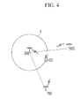
- a receiver 400 that is an object of wireless positioning receives reference signals for positioning from a plurality of transmitters around the receiver, for example, three transmitters 500 , 600 , and 700 .
- the receiver 400 analyzes the propagation delay tabs for the reference signals received from the transmitters 500 , 600 , and 700 , respectively.
- the receiver 400 knows the positions of the transmitters 500 , 600 , and 700 , the arrival time of the propagation delay having the largest signal intensity is the shortest in the transmitter 500 , and the arrival time of the propagation delay tabs having the largest signal intensity longest from the transmitter 600 to the transmitter 700 .
- the propagation environment between the receiver 400 and the transmitter 500 is close to the LOS environment, and the propagation environments are closer to the NLOS environment from the transmitter to the transmitter 700 .
- the transmitter 500 having the propagation environment closest to the LOS is a reference transmitter.
- the receiver 400 measures the distance between the reference transmitter 500 and the receiver 400 , using the arrival time and light speed of the propagation delay tab arriving first in the propagation delay tabs of the reference transmitter 500 .
- the receiver 400 determines that the receiver 400 is positioned on a circle spaced apart as much as the calculated distance from the reference transmitter 500 because the propagation environment determined by the propagation delay tab is LOS.
- the receiver 400 measures the distance between the transmitter 600 having the propagation environment that is close to the LOS environment, next to the reference transmitter 500 , and the receiver 400 and forms a circle Y having a center at the transmitter 600 .
- the distance between the transmitter 600 and the receiver 400 can be measured by using the arrival time and light speed of the propagation delay tab arriving the first in the propagation delay tabs of the transmitter 600 .
- the receiver 400 can determine that the receiver 400 is positioned at an intersection C or an intersection E of the circle Y having a center at the transmitter 600 and the circle X having a center at the transmitter 500 .
- the receiver 400 corrects the intersection C calculated through the process descried with reference to FIG. 4 and FIG. 5 in the direction of the transmitter 700 .
- a start point for a position correction is the intersection C by a circle Z having a center at the transmitter 700 .
- the receiver 400 can perform the correction that the receiver 400 is positioned at any point D on the straight line connecting the intersection C with the transmitter 700 .
- the receiver 400 calculates the distance between the transmitter 700 having the propagation environments close to the NLOS environment and the receiver 400 , and set a circle Z having a center at the transmitter.
- the position of the receiver 400 can be corrected to the intersection of the straight line connecting the intersection C with the position of the transmitter 700 and a circle Z having a center at the transmitter 700 .
- the correction method is not limited thereto.
- the distance may be corrected by various methods based on the circle Z. For example, if a radius of the circle Z is large, the distance may be corrected from the intersection E.
- the receiver may receive reference signals for positioning from three transmitters, and may perform positioning on the basis of the received reference signals according to the propagation environment priority of LOS.
- the above-mentioned exemplary embodiments of the present invention are not embodied only by an apparatus and method.
- the above-mentioned exemplary embodiments may be embodied by a program performing functions, which correspond to the configuration of the exemplary embodiments of the present invention, or a recording medium on which the program is recorded.
Abstract
Provides are method and apparatus for wireless positioning. An exemplary embodiment of the present invention provides a method for wireless positioning, which includes: receiving signals from a plurality of transmitters; determining propagation delay tabs of the plurality of transmitters, from the signals received from the plurality of transmitters, respectively; setting the order of the plurality of transmitters in accordance with the propagation delay tabs; measuring distances between a receiver and the transmitter, respectively; and estimating the position of the receiver, by using the order and the measured distance.
Description
- This application claims priority to and the benefit of Korean Patent Application No. 10-2009-0093228 and 10-2010-0095194 filed in the Korean Intellectual Property Office on Sep. 30, 2009 and Sep. 30, 2010, the entire contents of which are incorporated herein by reference.
- (a) Field of the Invention
- The present invention relates to a method and apparatus for positioning. More particularly, the present invention relates to a method and apparatus for wirelessly positioning a terminal on the basis of the types of propagation delay.
- (b) Description of the Related Art
- Wireless positioning is a technology of positioning a terminal, using a wireless communication system, and this field has been recently increased with the increase of demands for location based service (LBS). Particularly, the wireless positioning technology is increasingly under the spotlight, in accordance with the increase in demand for a technology that can provide users with appropriate service by determining the user's situation and position.
- Global positioning system (GPS) that is a representative wireless positioning technology provides positioning results with high accuracy, but has a problem in that a terminal in a room cannot receive a GPS signal and only a terminal equipped with a GPS receiver can receive a GPS signal.
- Accordingly, as another wireless positioning technology, an received signal strength indicator (RSSI) method and a time difference of arrival (TDOA) method have been considered. The RSSI method is a method of acquiring positional information, using the intensity of a received signal. According to the RSSI method, the positional information can be easily acquired because the structure is simple, but errors are generated due to path loss.
- The TDOA method is a method of acquiring positional information, using a difference in the arrival time of signals. According to the TDOA, time synchronization is not needed between a receiver and a transmitter, but time synchronization is required between the transmitters.
- The above-mentioned wireless positioning technology, for example, all of the GPS, RSSI method and TDOA method cannot provide accurate positioning results under a non-line of sight (NLOS) environment or an environment having a bad channel condition. Accordingly, a method that provides an accurate positioning result by reflecting the propagation environment of signals is required.
- The present invention has been made in an effort to provide a method and apparatus for wireless positioning having advantages of considering the types of propagation delay.
- An exemplary embodiment of the present invention provides a method for wireless positioning, which includes: receiving signals from a plurality of transmitters; determining propagation delay tabs of the plurality of transmitters, from the signals received from the plurality of transmitters, respectively; setting the order of the plurality of transmitters in accordance with the propagation delay tabs; measuring distances between a receiver and the transmitter, respectively; and estimating the position of the receiver, by using the order and the measured distance.
- Another exemplary embodiment of the present invention provides a method for wireless positioning, which includes: receiving signals from a plurality of transmitters; determining propagation delay tabs of the plurality of transmitters, from the signals received from the plurality of transmitters; setting a reference transmitter in the plurality of transmitters on the basis of the plurality of propagation delay tabs; estimating the position of a receiver by using the distance between a receiver and the reference transmitter; and correcting the position of the receiver by using the distance between the receiver and the other transmitters, except for the reference transmitter, in the plurality of transmitters.
- Yet another exemplary embodiment of the present invention provides an apparatus for wireless positioning that includes: a signal receiving unit that receives signals from a plurality of transmitters; a propagation environment determining unit that determines propagation delay tabs of the plurality of transmitters, from the signal received from the plurality of transmitters; a transmitter order setting unit that sets the order of the plurality of transmitters in accordance with the propagation delay tabs; a distance measuring unit that measures the distance between the receiver and each of the transmitters; and a position estimating unit that estimates the position of the receiver by using the order and the measured distances.
-
FIG. 1A toFIG. 1D are diagrams showing a type of propagation delay tab. -
FIG. 2 is an apparatus for wireless positioning according to an exemplary embodiment of the present invention. -
FIG. 3 is a method of wireless positioning according to an exemplary embodiment of the present invention. The apparatus for wireless positioning may be a part of a receiver. -
FIG. 4 toFIG. 6 are diagrams exemplifying a method of estimating the position of a receiver by an apparatus for wireless positioning according to an exemplary embodiment of the present invention. - In the following detailed description, only certain exemplary embodiments of the present invention have been shown and described, simply by way of illustration. As those skilled in the art would realize, the described embodiments may be modified in various different ways, all without departing from the spirit or scope of the present invention. Accordingly, the drawings and description are to be regarded as illustrative in nature and not restrictive. Like reference numerals designate like elements throughout the specification.
- In the specification, unless explicitly described to the contrary, the word “comprise” and variations such as “comprises” or “comprising”, will be understood to imply the inclusion of stated elements but not the exclusion of any other elements.
- In the specification, a terminal may designate a mobile station (MS), mobile terminal (MT), a subscriber station (SS), a portable subscriber station (PSS), a user equipment (UE), and an access terminal (AT), etc. and may include the entire or partial functions of the terminal, the mobile station, the mobile terminal, the subscriber station, the portable subscriber station, the user equipment, the access terminal, etc.
- In the specification, a base station (BS) may designate a radio access station (RAS), a node B, an evolved node B (eNodeB), a base transceiver station (BTS), and a mobile multihop relay (MMR)-BS, etc. and may include the entire or partial functions of the base station, the radio access station, the node B, the enodeB, the base transceiver station, and the MMR-BS, etc.
- Hereinafter, method and apparatus for wireless positioning according to an exemplary embodiment of the present invention will be described in detail with reference to the accompanying drawing.
-
FIG. 1A toFIG. 1D are diagrams showing a type of propagation delay tab. - A propagation delay tab means that a signal transmitted from a transmitter under a multipath environment is a delay spread shape. When a geographical obstacle exists between a transmitter and a receiver, a multipath is formed by reflection or diffraction of a signal due to the obstacle. Therefore, one signal transmitted from the transmitter is delay-spread through the multipath.
- Referring to
FIG. 1A , the signal intensity of apropagation delay tab 10 which earliest arrives at the receiver is largest. When an geographical obstacle does not exist between the transmitter and the receiver, a signal transmitted from the transmitter can arrive at the receiver, with high signal intensity within a short time. Accordingly, the type ofFIG. 1A may be a type of propagation delay under an line of sight (LOS) environment. - Referring to
FIG. 1B , the signal intensity of apropagation delay tab 21 which arrives second at the receiver is the largest, and the signal intensity of apropagation delay tabs 20 that arrives first is smaller than the signal intensity of apropagation delay tab 21. - Referring to
FIG. 10 , the signal intensity of apropagation delay tab 31 which arrives third at the receiver is the largest, and the signal intensity of apropagation delay tabs 30 that arrives first is smaller than the signal intensity of apropagation delay tab 31. - Referring to
FIG. 1D , the signal intensity of apropagation delay tab 41 which arrives latest at the receiver is the largest, and the signal intensity of apropagation delay tabs 40 that arrives first is smaller than the signal intensity of apropagation delay tab 41. - As the types of propagation delay tab become similar to the types of
FIG. 1A , the environment between the transmitter and the receiver is close to the LOS environment. Further, as the type of propagation delay tabs becomes similar to the types ofFIG. 1D , the environment between the transmitter and the receiver is close to the non-line of sight environment. -
FIG. 2 is a diagram showing an apparatus for wireless positioning according to an exemplary embodiment of the present invention andFIG. 3 is a diagram showing a method for wireless positioning according to an exemplary embodiment of the present invention. The apparatus for wireless positioning may be a part of a receiver. Assume that the apparatus for wireless positioning knows the position of a peripheral transmitter. - Referring to
FIG. 2 , anapparatus 200 for wireless positioning includes asignal receiving unit 210, a propagationenvironment determining unit 220, a transmitterorder setting unit 230, adistance measuring unit 240, and aposition estimating unit 250. - Referring to
FIG. 2 andFIG. 3 , thesignal receiving unit 210 receives signals transmitted from a plurality of transmitters (S300). The signals transmitted from the transmitter, for example, may be reference signals for positioning. Hereinafter, it is exemplified that thesignal receiving unit 210 receives reference signals for positioning from the plurality of transmitters, respectively. - The propagation
environment determining unit 220 determines propagation delay tabs for the signals transmitted from the plurality of transmitters (S310). In other words, the propagationenvironment determining unit 220 determines the arrival time of a propagation delay tab having the largest signal intensity in the propagation delay tabs of each of the transmitters. Meanwhile, the propagationenvironment determining unit 220 can determine the propagation environment on the basis of the propagation delay tabs. For example, when the types of propagation delay tabs for signals transmitted from the transmitters are similar toFIG. 1A , that is, it is determined that the propagation environment between the transmitters and corresponding receivers is the LOS environment, as the signal intensity of the propagation delay tabs arriving first is the largest. As another example, when the type of propagation delay tabs for the signals transmitted from the transmitter are similar toFIG. 1B toFIG. 1D , that is, it is determined that the propagation environment between the transmitters and corresponding receivers is close to the NLOS environment, as the propagation delay tab having the largest signal intensity arrives late. - The transmitter
order setting unit 230 sets the order of the transmitters, using the results determined by the propagation environment determining unit 220 (S320). For example, the order may be set as a prior order, as the propagation environment is close to the LOS environment, and the order is set as a latter order, as the propagation environment may be close to the NLOS environment. - The
distance measuring unit 240 measures the distances between the transmitters and the receivers (S330). In this case, the distance measuring unit can measures the distance between the transmitter and the receiver, respectively, using the arrival time of the propagation delay tab arriving first in the propagation delay tabs of the transmitters. - The
position estimating unit 250 estimates the positions of the receiver, using the order set by the transmitterorder setting unit 230 and the distances measured by the distance measuring unit 240 (S340). For example, it is possible to estimate the position of the receiver on the basis of the distance between the prior order transmitter and the receiver and to correct the position of the receiver by using the distance between the latter order transmitter and the receiver. - Hereinafter, a detailed method of estimating the position of a receiver by the apparatus for wireless positioning will be described.
-
FIG. 4 toFIG. 6 are diagrams exemplifying a method of estimating the position of a receiver by an apparatus for wireless positioning according to an exemplary embodiment of the present invention. - Referring to
FIG. 4 toFIG. 6 , areceiver 400 that is an object of wireless positioning receives reference signals for positioning from a plurality of transmitters around the receiver, for example, threetransmitters receiver 400 analyzes the propagation delay tabs for the reference signals received from thetransmitters receiver 400 knows the positions of thetransmitters transmitter 500, and the arrival time of the propagation delay tabs having the largest signal intensity longest from thetransmitter 600 to thetransmitter 700. Accordingly, assume that the propagation environment between thereceiver 400 and thetransmitter 500 is close to the LOS environment, and the propagation environments are closer to the NLOS environment from the transmitter to thetransmitter 700. - Referring to
FIG. 4 , thetransmitter 500 having the propagation environment closest to the LOS is a reference transmitter. Thereceiver 400 measures the distance between thereference transmitter 500 and thereceiver 400, using the arrival time and light speed of the propagation delay tab arriving first in the propagation delay tabs of thereference transmitter 500. Thereceiver 400 determines that thereceiver 400 is positioned on a circle spaced apart as much as the calculated distance from thereference transmitter 500 because the propagation environment determined by the propagation delay tab is LOS. - Referring to
FIG. 5 , thereceiver 400 measures the distance between thetransmitter 600 having the propagation environment that is close to the LOS environment, next to thereference transmitter 500, and thereceiver 400 and forms a circle Y having a center at thetransmitter 600. The distance between thetransmitter 600 and thereceiver 400 can be measured by using the arrival time and light speed of the propagation delay tab arriving the first in the propagation delay tabs of thetransmitter 600. - Accordingly, the
receiver 400 can determine that thereceiver 400 is positioned at an intersection C or an intersection E of the circle Y having a center at thetransmitter 600 and the circle X having a center at thetransmitter 500. - Referring to
FIG. 6 , thereceiver 400 corrects the intersection C calculated through the process descried with reference toFIG. 4 andFIG. 5 in the direction of thetransmitter 700. In this case, a start point for a position correction is the intersection C by a circle Z having a center at thetransmitter 700. In other words, thereceiver 400 can perform the correction that thereceiver 400 is positioned at any point D on the straight line connecting the intersection C with thetransmitter 700. For example, thereceiver 400 calculates the distance between thetransmitter 700 having the propagation environments close to the NLOS environment and thereceiver 400, and set a circle Z having a center at the transmitter. Further, the position of thereceiver 400 can be corrected to the intersection of the straight line connecting the intersection C with the position of thetransmitter 700 and a circle Z having a center at thetransmitter 700. The correction method is not limited thereto. The distance may be corrected by various methods based on the circle Z. For example, if a radius of the circle Z is large, the distance may be corrected from the intersection E. - In the above, for better comprehension and ease of description, although it is assumed that the receiver receives reference signals for positioning from three transmitters, the scope of the present invention is not limited thereto. The receiver may receive reference signals for positioning from three or more transmitters, and may perform positioning on the basis of the received reference signals according to the propagation environment priority of LOS.
- As described above, when the wireless positioning is performed on the basis of types of the propagation delay tabs, an error of wireless positioning generated when the propagation environments are close to the NLOS environment can be reduced.
- According to the exemplary embodiments of the present invention, method and apparatus for wireless positioning, considering the types of propagation delay are provided. Accordingly, it is possible to reduce errors in positioning, according to the propagation environment between transmitters and a receiver.
- The above-mentioned exemplary embodiments of the present invention are not embodied only by an apparatus and method. Alternatively, the above-mentioned exemplary embodiments may be embodied by a program performing functions, which correspond to the configuration of the exemplary embodiments of the present invention, or a recording medium on which the program is recorded.
- While this invention has been described in connection with what is presently considered to be practical exemplary embodiments, it is to be understood that the invention is not limited to the disclosed embodiments, but, on the contrary, is intended to cover various modifications and equivalent arrangements included within the spirit and scope of the appended claims.
Claims (17)
1. A method for wireless positioning, comprising:
receiving signals from a plurality of transmitters;
determining propagation delay tabs of the plurality of transmitters, from the signals received from the plurality of transmitters, respectively;
setting the order of the plurality of transmitters in accordance with the propagation delay tabs;
measuring distances between a receiver and the transmitter, respectively; and
estimating the position of the receiver, by using the order and the measured distance.
2. The method of claim 1 , wherein:
the transmitted signals are reference signals for wireless positioning.
3. The method of claim 1 , wherein:
the setting of the order includes
setting the order of the plurality of transmitters, in accordance with arrival time of a propagation delay tab having the largest signal intensity in the propagation delay tabs of the plurality of transmitters and a LOS propagation delay priority.
4. The method of claim 3 , wherein:
the transmitters having shorter arrival time of the propagation delay tab having the largest signal intensity are set to prior orders.
5. The method of claim 1 , wherein:
the setting of the order includes:
determining the propagation environment of the plurality of transmitters in accordance with the propagation delay tabs; and
setting the transmitters having the propagation environments closer to line of sight (LOS) environment to prior orders.
6. The method of claim 1 , wherein:
the distance between the receiver and each of the transmitter is calculated by using the arrival time of the propagation delay tab arriving first in the propagation delay tabs of each of the transmitters.
7. The method of claim 1 , wherein:
the estimating the position includes:
estimating the position of the receiver on the basis of the distance between a prior order transmitter and the receiver; and
correcting the position of the receiver by using the distance between a latter order transmitter and the receiver.
8. A method for wireless positioning, comprising:
receiving signals from a plurality of transmitters;
determining propagation delay tabs of the plurality of transmitters, from the signals received from the plurality of transmitters;
setting a reference transmitter in the plurality of transmitters on the basis of the plurality of propagation delay tabs;
estimating the position of the receiver by using the distance between a receiver and the reference transmitter; and
correcting the position of the receiver by using the distance between the receiver and the other transmitters, except for the reference transmitter in the plurality of transmitters.
9. The method of claim 8 , further comprising:
calculating the distance between the receiver and each of the transmitters, by using arrival time of the propagation delay tab arriving first in the propagation delay tabs of each of the transmitters.
10. The method of claim 8 , wherein:
the estimating of position of the receiver includes
estimating that the receiver is positioned on a position constructed by intersections of a circle having a center at the reference transmitter and a radius that is the distance between the receiver and the reference transmitter and a circle having a radius that is a distance between the receiver and a second prior order transmitter.
11. The method of claim 10 , wherein:
the correcting of position of the receiver includes
correcting the position of the receiver by using two intersections of a circle having a center at a first transmitter in the other transmitters and a radius that is the distance between the receiver and the first transmitter and a circle having a radius that is the distance between the receiver and a second prior order transmitter.
12. The method of claim 11 , wherein:
the correcting of position of the receiver further includes
additionally correcting the position of the receiver to a point where a circle having a center at a second transmitter in the other transmitters and having a radius that is the distance between the receiver and the second transmitter intersects a straight line connecting the intersection with the second transmitter.
13. The method of claim 8 , wherein:
the setting a reference transmitter includes
setting a transmitter having the shortest arrival time of the propagation delay tab having the largest signal intensity, as the reference transmitter, in the plurality of transmitters.
14. The method of claim 8 , wherein:
the setting of a reference transmitter includes:
determining propagation environments of the plurality of transmitters in accordance with the propagation delay tabs;
setting a transmitter having the propagation environment closest to line of sight (LOS) environment as the reference transmitter.
15. An apparatus for wireless positioning, comprising:
a signal receiving unit that receives signals from a plurality of transmitters;
a propagation environment determining unit that determines propagation delay tabs of the plurality of transmitters, from the signal received from the plurality of transmitters;
a transmitter order setting unit that sets the order of the plurality of transmitters in accordance with the propagation delay tabs;
a distance measuring unit that measures the distance between the receiver and each of the transmitters; and
a position estimating unit that estimates the position of the receiver by using the order and the measured distances.
16. The apparatus of claim 15 , wherein:
the transmitter order setting unit sets a transmitter having the shortest arrival time of a propagation delay tab having the largest signal intensity in the plurality of transmitters, as the reference transmitter.
17. The apparatus of claim 16 , wherein:
the position estimating unit sets the position of the receiver by using the distance between the receiver and the reference transmitter, and corrects the position of the receiver by using the distances between the receiver and the other transmitters, except for the reference transmitter, in the plurality of transmitters.
Applications Claiming Priority (4)
| Application Number | Priority Date | Filing Date | Title |
|---|---|---|---|
| KR10-2009-0093228 | 2009-09-30 | ||
| KR20090093228 | 2009-09-30 | ||
| KR1020100095194A KR20110035984A (en) | 2009-09-30 | 2010-09-30 | Method and apparatus for positioning |
| KR10-2010-0095194 | 2010-09-30 |
Publications (1)
| Publication Number | Publication Date |
|---|---|
| US20110074635A1 true US20110074635A1 (en) | 2011-03-31 |
Family
ID=43779723
Family Applications (1)
| Application Number | Title | Priority Date | Filing Date |
|---|---|---|---|
| US12/895,006 Abandoned US20110074635A1 (en) | 2009-09-30 | 2010-09-30 | Method and apparatus for positioning |
Country Status (1)
| Country | Link |
|---|---|
| US (1) | US20110074635A1 (en) |
Cited By (6)
| Publication number | Priority date | Publication date | Assignee | Title |
|---|---|---|---|---|
| CN102508201A (en) * | 2011-10-26 | 2012-06-20 | 青岛理工大学 | Field positioning method based on wireless positioning device for agricultural machinery |
| CN102680941A (en) * | 2012-06-01 | 2012-09-19 | 中国矿业大学(北京) | Method and system for ultra wide band positioning in coal mine |
| CN104698437A (en) * | 2015-03-27 | 2015-06-10 | 北京矿冶研究总院 | Underground vehicle positioning method based on ultra wide band |
| EP3176600A1 (en) * | 2015-12-03 | 2017-06-07 | ST SPORTSERVICE GmbH | Method for calculating a position of an object of interest |
| CN106932751A (en) * | 2017-04-01 | 2017-07-07 | 昆明理工大学 | The localization method of handheld terminal in a kind of high accuracy office building |
| US9851430B2 (en) | 2014-07-11 | 2017-12-26 | Electronics And Telecommunications Research Institute | Positioning method and apparatus using wireless signal |
Citations (5)
| Publication number | Priority date | Publication date | Assignee | Title |
|---|---|---|---|---|
| US20010051527A1 (en) * | 2000-06-13 | 2001-12-13 | Mikio Kuwahara | Wireless position measurement terminal and wireless position measurement system |
| US7072673B2 (en) * | 2001-07-24 | 2006-07-04 | Hitachi, Ltd. | Radio handset and position location system |
| US7358899B1 (en) * | 2000-08-31 | 2008-04-15 | Nokia Corporation | Distance estimation in a communication system |
| US20090017837A1 (en) * | 2004-09-17 | 2009-01-15 | Kim Ii Tae | System and method for determining position of mobile communication device |
| US7737893B1 (en) * | 2006-06-28 | 2010-06-15 | Rosum Corporation | Positioning in a single-frequency network |
-
2010
- 2010-09-30 US US12/895,006 patent/US20110074635A1/en not_active Abandoned
Patent Citations (5)
| Publication number | Priority date | Publication date | Assignee | Title |
|---|---|---|---|---|
| US20010051527A1 (en) * | 2000-06-13 | 2001-12-13 | Mikio Kuwahara | Wireless position measurement terminal and wireless position measurement system |
| US7358899B1 (en) * | 2000-08-31 | 2008-04-15 | Nokia Corporation | Distance estimation in a communication system |
| US7072673B2 (en) * | 2001-07-24 | 2006-07-04 | Hitachi, Ltd. | Radio handset and position location system |
| US20090017837A1 (en) * | 2004-09-17 | 2009-01-15 | Kim Ii Tae | System and method for determining position of mobile communication device |
| US7737893B1 (en) * | 2006-06-28 | 2010-06-15 | Rosum Corporation | Positioning in a single-frequency network |
Cited By (8)
| Publication number | Priority date | Publication date | Assignee | Title |
|---|---|---|---|---|
| CN102508201A (en) * | 2011-10-26 | 2012-06-20 | 青岛理工大学 | Field positioning method based on wireless positioning device for agricultural machinery |
| CN102680941A (en) * | 2012-06-01 | 2012-09-19 | 中国矿业大学(北京) | Method and system for ultra wide band positioning in coal mine |
| US9851430B2 (en) | 2014-07-11 | 2017-12-26 | Electronics And Telecommunications Research Institute | Positioning method and apparatus using wireless signal |
| CN104698437A (en) * | 2015-03-27 | 2015-06-10 | 北京矿冶研究总院 | Underground vehicle positioning method based on ultra wide band |
| EP3176600A1 (en) * | 2015-12-03 | 2017-06-07 | ST SPORTSERVICE GmbH | Method for calculating a position of an object of interest |
| WO2017093496A1 (en) * | 2015-12-03 | 2017-06-08 | Swiss Timing Ltd | Method for calculating a position of an object of interest |
| US10698071B2 (en) | 2015-12-03 | 2020-06-30 | Swiss Timing Ltd | Method for calculating a position of an object of interest |
| CN106932751A (en) * | 2017-04-01 | 2017-07-07 | 昆明理工大学 | The localization method of handheld terminal in a kind of high accuracy office building |
Similar Documents
| Publication | Publication Date | Title |
|---|---|---|
| US20110074634A1 (en) | Wireless positioning method and apparatus | |
| US8472971B2 (en) | Method and apparatus for determining whether a mobile terminal has moved outside a given locale | |
| US8576122B2 (en) | Method for measuring location of mobile terminal | |
| US9584981B2 (en) | Method and apparatus for real-time, mobile-based positioning according to sensor and radio frequency measurements | |
| US8121621B2 (en) | Position estimation system | |
| US7400890B2 (en) | Method for decision of time delay by repeater in mobile communication network | |
| US20070252761A1 (en) | Method and arrangement for base station location, base station synchronization, and mobile station location | |
| US20110074635A1 (en) | Method and apparatus for positioning | |
| US20110074632A1 (en) | Wireless positioning method and apparatus | |
| US20080194226A1 (en) | Method and Apparatus for Providing Location Services for a Distributed Network | |
| US20040023671A1 (en) | Method for enhanced mobile assisted positioning | |
| KR20120092156A (en) | Tdoa based positioning with calculation of correction factors for compensating the clock offsets of unsynchronized network stations | |
| US8620355B2 (en) | Method and apparatus for determining the position of a wireless terminal based on propagation delay taps of base stations | |
| JP2006080681A (en) | System and method for position detection | |
| CN103582115A (en) | Positioning method, control equipment and mobile communication system | |
| KR102488643B1 (en) | Apparatus for precise positioning compensation using positioning difference and method thereof | |
| KR20090129835A (en) | Apparatus and system for estimating position of terminal | |
| US8150378B2 (en) | Determining position of a node based on aged position data | |
| CN111417188A (en) | Terminal positioning method and device and storage medium | |
| KR20110035983A (en) | Method and apparatus for positioning | |
| US8125943B2 (en) | Method for positioning user equipment accessing multiple mobile networks | |
| KR100857749B1 (en) | Repeater identification in a position determination system | |
| US20100136999A1 (en) | Apparatus and method for determining position of terminal | |
| KR101691181B1 (en) | Method and apparatus for positioning | |
| US20120184297A1 (en) | Wireless location measurement method |
Legal Events
| Date | Code | Title | Description |
|---|---|---|---|
| AS | Assignment |
Owner name: ELECTRONICS AND TELECOMMUNICATIONS RESEARCH INSTIT Free format text: ASSIGNMENT OF ASSIGNORS INTEREST;ASSIGNORS:YEO, GEON MIN;RYU, BYUNG-HAN;PARK, HYEONG JUN;AND OTHERS;REEL/FRAME:025159/0669 Effective date: 20100930 |
|
| STCB | Information on status: application discontinuation |
Free format text: ABANDONED -- FAILURE TO RESPOND TO AN OFFICE ACTION |