US20120249368A1 - Method and apparatus for determining a position of a gnss receiver - Google Patents
Method and apparatus for determining a position of a gnss receiver Download PDFInfo
- Publication number
- US20120249368A1 US20120249368A1 US13/434,684 US201213434684A US2012249368A1 US 20120249368 A1 US20120249368 A1 US 20120249368A1 US 201213434684 A US201213434684 A US 201213434684A US 2012249368 A1 US2012249368 A1 US 2012249368A1
- Authority
- US
- United States
- Prior art keywords
- gnss
- candidate
- pseudoranges
- receiver
- satellites
- Prior art date
- Legal status (The legal status is an assumption and is not a legal conclusion. Google has not performed a legal analysis and makes no representation as to the accuracy of the status listed.)
- Abandoned
Links
Images


Classifications
-
- G—PHYSICS
- G01—MEASURING; TESTING
- G01S—RADIO DIRECTION-FINDING; RADIO NAVIGATION; DETERMINING DISTANCE OR VELOCITY BY USE OF RADIO WAVES; LOCATING OR PRESENCE-DETECTING BY USE OF THE REFLECTION OR RERADIATION OF RADIO WAVES; ANALOGOUS ARRANGEMENTS USING OTHER WAVES
- G01S19/00—Satellite radio beacon positioning systems; Determining position, velocity or attitude using signals transmitted by such systems
- G01S19/01—Satellite radio beacon positioning systems transmitting time-stamped messages, e.g. GPS [Global Positioning System], GLONASS [Global Orbiting Navigation Satellite System] or GALILEO
- G01S19/13—Receivers
- G01S19/22—Multipath-related issues
-
- G—PHYSICS
- G01—MEASURING; TESTING
- G01S—RADIO DIRECTION-FINDING; RADIO NAVIGATION; DETERMINING DISTANCE OR VELOCITY BY USE OF RADIO WAVES; LOCATING OR PRESENCE-DETECTING BY USE OF THE REFLECTION OR RERADIATION OF RADIO WAVES; ANALOGOUS ARRANGEMENTS USING OTHER WAVES
- G01S19/00—Satellite radio beacon positioning systems; Determining position, velocity or attitude using signals transmitted by such systems
- G01S19/38—Determining a navigation solution using signals transmitted by a satellite radio beacon positioning system
- G01S19/39—Determining a navigation solution using signals transmitted by a satellite radio beacon positioning system the satellite radio beacon positioning system transmitting time-stamped messages, e.g. GPS [Global Positioning System], GLONASS [Global Orbiting Navigation Satellite System] or GALILEO
- G01S19/42—Determining position
- G01S19/48—Determining position by combining or switching between position solutions derived from the satellite radio beacon positioning system and position solutions derived from a further system
-
- G—PHYSICS
- G01—MEASURING; TESTING
- G01S—RADIO DIRECTION-FINDING; RADIO NAVIGATION; DETERMINING DISTANCE OR VELOCITY BY USE OF RADIO WAVES; LOCATING OR PRESENCE-DETECTING BY USE OF THE REFLECTION OR RERADIATION OF RADIO WAVES; ANALOGOUS ARRANGEMENTS USING OTHER WAVES
- G01S19/00—Satellite radio beacon positioning systems; Determining position, velocity or attitude using signals transmitted by such systems
- G01S19/01—Satellite radio beacon positioning systems transmitting time-stamped messages, e.g. GPS [Global Positioning System], GLONASS [Global Orbiting Navigation Satellite System] or GALILEO
- G01S19/13—Receivers
- G01S19/24—Acquisition or tracking or demodulation of signals transmitted by the system
- G01S19/26—Acquisition or tracking or demodulation of signals transmitted by the system involving a sensor measurement for aiding acquisition or tracking
-
- G—PHYSICS
- G01—MEASURING; TESTING
- G01S—RADIO DIRECTION-FINDING; RADIO NAVIGATION; DETERMINING DISTANCE OR VELOCITY BY USE OF RADIO WAVES; LOCATING OR PRESENCE-DETECTING BY USE OF THE REFLECTION OR RERADIATION OF RADIO WAVES; ANALOGOUS ARRANGEMENTS USING OTHER WAVES
- G01S19/00—Satellite radio beacon positioning systems; Determining position, velocity or attitude using signals transmitted by such systems
- G01S19/38—Determining a navigation solution using signals transmitted by a satellite radio beacon positioning system
- G01S19/39—Determining a navigation solution using signals transmitted by a satellite radio beacon positioning system the satellite radio beacon positioning system transmitting time-stamped messages, e.g. GPS [Global Positioning System], GLONASS [Global Orbiting Navigation Satellite System] or GALILEO
- G01S19/42—Determining position
- G01S19/421—Determining position by combining or switching between position solutions or signals derived from different satellite radio beacon positioning systems; by combining or switching between position solutions or signals derived from different modes of operation in a single system
- G01S19/426—Determining position by combining or switching between position solutions or signals derived from different satellite radio beacon positioning systems; by combining or switching between position solutions or signals derived from different modes of operation in a single system by combining or switching between position solutions or signals derived from different modes of operation in a single system
Definitions
- the present application relates methods and apparatus for acquiring satellites in a Global Navigation Satellite System (GNSS) and fixing a position of a GNSS receiver.
- GNSS Global Navigation Satellite System
- a Global Navigation Satellite System (GNSS) receiver requires information from at least four GNSS satellites in order to determine its three dimensional position.
- the approximate distance between a GNSS satellite and a receiver is generally referred to as a pseudorange.
- the location of the GNSS satellites relative to the receiver has a major impact on the overall accuracy of the determined three dimensional position.
- good satellite geometry occurs when satellites are evenly scattered relative to the receiver.
- a stand-alone GNSS receiver may fail to fix its three-dimensional position.
- Difficulty in acquiring satellites is typically due to signal degradation and unavailability of satellites in challenging environments such as indoors, in densely forested areas or in deep urban locations, for example, where attenuation and multipath effects make it difficult for the GNSS receiver to discriminate and acquire information from the required number of GNSS satellites.
- Non-GNSS positioning techniques use several technologies such as WiFi and Cellular-based positioning, for example, which can provide a source of additional information to assist a stand-alone GNSS receiver when it cannot acquire a sufficient number of GNSS satellites or in the case of bad satellite geometry.
- Cooperation between a GNSS receiver and any other positioning technology is referred to as Assisted-GNSS (A-GNSS).
- the assistance information generally includes ephemeris data (real or synthetic), timing data and/or position estimation.
- GNSS Global Positioning System
- a well known GNSS is the Global Positioning System (GPS).
- GPS Global Positioning System
- A-GPS Assisted-GPS
- the initial position assistance may be used as an aid by the receiver to allow the receiver to focus on signals from satellites passing overhead. More generally, however, the initial position assistance just provides a fallback position in case the GPS receiver still fails to acquire information from a sufficient number of satellites or in case of bad satellite geometry.
- Such methods have been described as hybrid positioning and generally involve an either/or selection between the outputs of two or more positioning technologies including GPS, A-GPS, WiFi and Cellular-based positioning, for example.
- a method of determining a position of a GNSS receiver including: receiving, at the GNSS receiver, information from at least two GNSS satellites; receiving, at the GNSS receiver, an estimated location area from a non-GNSS positioning application; determining candidate pseudoranges corresponding to candidate correlation peaks determined based on the information received from the at least two GNSS satellites; determining possible positions of the GNSS receiver using the candidate pseudoranges and the estimated location area; determining a best possible position of the GNSS receiver from the possible positions; and setting the best possible position as the position of the GNSS receiver; wherein when multiple candidate correlation peaks corresponding to one of the at least two GNSS satellites are determined, the estimated location area is usable to reduce the number of candidate correlation peaks prior to candidate pseudoranges being determined.
- a mobile device including: an antenna; a GNSS receiver for receiving information from at least two GNSS satellites and for receiving an estimated location area from a non-GNSS positioning application; and a processor in communication with the GNSS receiver; the processor determining candidate pseudoranges corresponding to candidate correlation peaks determined based on the information received from the at least two GNSS satellites, determining a best possible position of the GNSS receiver from possible positions of the GNSS receiver determined using the candidate pseudoranges and the estimated location area and setting the best possible position as the position of the GNSS receiver; wherein when multiple candidate correlation peaks corresponding to one of the at least two GNSS satellites are determined, the estimated location area is usable to reduce the number of candidate correlation peaks prior to candidate pseudoranges being determined.
- non-GNSS technologies collaborate with a GNSS receiver and provide positioning information to facilitate fixing of a position of a GNSS receiver when the GNSS receiver is unable to fix its position independently.
- FIG. 1 is a schematic diagram of some components of a mobile device including a GPS receiver in communication with GPS satellites;
- FIG. 2 is a block diagram of components of the mobile device of FIG. 1 ;
- FIG. 3 is a block diagram of a GPS receiver in communication with GPS satellites and a non-GNSS positioning application
- FIG. 4 is a block diagram depicting operation of a GPS receiver according to an embodiment
- FIG. 5 is a flow diagram depicting processing of correlation peaks
- FIG. 6 is a flow diagram depicting operation of a satellite acquisition application
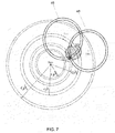
- FIG. 7 is a schematic diagram showing possible positions of a GPS receiver as determined using the satellite acquisition application
- FIG. 8 is a flow diagram depicting a method of determining a position of a GPS receiver using assisted positioning information from a non-GNSS positioning application
- FIG. 9A is a schematic diagram showing two possible positions of a GPS receiver when information from two GPS satellites is received.
- FIG. 9B is a schematic diagram showing possible positions of a GPS receiver determined using the method of FIG. 8 ;
- FIG. 9C is a schematic diagram showing possible positions of a GPS receiver as determined using a hybrid positioning system of the prior art.
- FIG. 10 is a schematic diagram depicting operating of a GPS receiver using a satellite acquisition application and a position determining application according to an embodiment
- FIG. 11 is a schematic diagram showing possible positions of a GPS receiver using a satellite acquisition application and a position determining application according to an embodiment.
- FIG. 12 is a flowchart depicting collaboration between the GPS receiver, satellite acquisition application, position determining application and position assisted-GPS application.
- GPS is referred to throughout the present application by way of example only.
- the methods and apparatus of the present application are applicable to any GNSS.
- a mobile device 10 receives information from GPS satellites in order to determine its position.
- the mobile device 10 may be a cell phone, a personal digital assistant, a Smartphone, an asset tracking device, a tablet or laptop computer, a navigation device or another device that is capable of determining its position with the help of a non-GNSS positioning application.
- assisted position information derived from a non-GNSS positioning application includes at least initial, or coarse, position assistance, which helps the GPS receiver 14 locate the GPS satellites passing overhead more quickly than a stand-alone GPS receiver, for example.
- the assisted position information derived from a non-GNSS positioning application may be available locally, on the mobile device 10 , may be available through direct communication with a computer or may be available via wireless communication with a server or database.
- the mobile device 10 includes an antenna 12 for receiving wireless signals, a GPS receiver 14 in communication with the antenna 12 , a processor 16 in communication with the antenna 12 and the receiver 14 .
- the mobile device 10 further includes a memory 18 that communicates with the processor 16 .
- the mobile device 10 may communicate with a computer to receive an estimated location area from a non-GNSS positioning application via a cellular data network, such as GPRS, EDGE, 3G, 4G, WLAN, 762.11 g, or 762.11n, for example.
- the mobile device 10 may further be capable of short range communication using BluetoothTM, for example.
- the mobile device 10 includes an antenna 12 and some GPS receiver components.
- the GPS receiver 14 may include a front end and a digitizer only.
- other GPS receiver components, the processor 16 and the memory 18 may be hosted remotely on a server, for example.
- the GPS receiver 14 is capable of receiving signals from GPS satellites and communicating with a non-GNSS positioning software application 20 .
- the non-GNSS positioning software application 20 may be stored as computer readable code in memory 18 of the mobile device 10 or, alternatively, stored on a server remote from the mobile device 10 .
- the non-GNSS positioning application 20 may be any positioning application capable of providing a coarse position estimate.
- Example of non-GNSS positioning applications include: WiFi-based positioning, cellular-based positioning (including but not limited to mobile standards such as GSM, CDMA, UMTS, LTE), land-mobile radio systems (including but not limited to VHF systems used in private or public safety applications), radio-broadcast positioning (including, but not limited position based on radio broadcast transmission towers such as FM or TV stations), or other data network infrastructure based positioning (including but not limited to IP routers, data modems or Internet protocols such as GeoIP).
- WiFi-based positioning including but not limited to mobile standards such as GSM, CDMA, UMTS, LTE
- land-mobile radio systems including but not limited to VHF systems used in private or public safety applications
- radio-broadcast positioning including, but not limited position based on radio broadcast transmission towers such as FM or TV stations
- other data network infrastructure based positioning including but not limited to IP routers, data modems or Internet protocols such as GeoIP).
- the GPS receiver 14 includes a signal processing unit 22 , which acquires satellites, and a navigation unit 24 , which fixes the position of the GPS receiver 14 .
- the GPS receiver 14 communicates with a satellite acquisition application 26 and a position determining application 28 .
- the satellite acquisition application 26 and the position determining application 28 are software applications that are stored as computer readable code in memory 18 and are executable by the processor 16 .
- the satellite acquisition application 26 identifies “true” or “best” pseudoranges when multiple candidate pseudoranges are determined in order to acquire more GPS satellites and the position determining application 28 reduces positioning uncertainty when satellite availability is limited.
- the GPS receiver 14 of FIG. 4 is capable of fixing its position when four or fewer satellites are acquired by the signal processing unit 22 .
- the signal processing unit of the GPS receiver 14 receives satellite signals from available GPS satellites and sends pre-processed digitized satellite signals (I, Q) to the satellite acquisition application 26 .
- the signal processing unit 22 determines and sends pseudoranges of acquired satellites to the navigation unit 24 , which in turn sends the pseudoranges of acquired satellites to the position determining application 28 .
- the estimated location area from the non-GNSS positioning application 20 is received by both the satellite acquisition application 26 and the position determining application 28 in order to fix a position of the GPS receiver 14 .
- the satellite signals and the estimated location area are received at generally the same time.
- the satellite acquisition application 26 uses the estimated location area from the non-GNSS positioning application 20 to discriminate between multiple candidate peaks in order to determine which one is the “true” or “best” correlation peak.
- the GPS receiver correlates the pre-processed satellite signal with its locally generated replicas, the GPS receiver: i) may not find any candidate correlation peaks in the signal, ii) may find multiple candidate correlation peaks due to signal attenuation or multipath, or iii) may find one distinct candidate correlation peak.
- a pseudorange associated with that candidate correlation peak is determined by the GPS receiver 14 to be an acquired satellite.
- correlation peaks are output from a correlator 30 , or matched filter, which is part of the signal processing unit 22 , of the GPS receiver 14 .
- the inputs of the correlator 30 are the GPS pre-processed signals and its replicas locally generated in the GPS receiver 14 .
- the correlator 30 may be referred to a grid of correlators because the correlator 30 includes a predefined search space. In prior art (assisted) GPS receivers, no satellite may be acquired unless a distinct correlation peak is found.
- correlators 30 use the estimated location area from the non-GNSS positioning application 20 to define a correlation search space, accelerate a search and reduce an area of uncertainty in order to extract a distinct correlation peak.
- multiple candidate correlation peaks are considered by the satellite acquisition application 26 .
- candidate pseudoranges that correspond to the multiple candidate correlation peaks are calculated.
- the estimated location area from the non-GNSS positioning application 20 is used in combination with pseudoranges of GPS satellites that have been acquired (i.e. satellites for which a distinct correlation peak was found) to select the “true” or “best” pseudorange out of the candidate pseudoranges when a “true” or “best” pseudorange exists.
- the satellite acquisition application 26 identifies candidate correlation peaks in the signal at 32 .
- no GPS satellite may be acquired at 34 .
- the GPS satellite is acquired at 36 .
- candidate correlation peaks are selected, at 38 , and candidate pseudoranges are determined at 40 .
- All of the candidate pseudoranges which includes the pseudoranges of GPS satellites that have been acquired, and the estimated location area from the non-GNSS positioning application 20 are used at 42 to: estimate the receiver's position using an estimator, which is part of the satellite acquisition application 26 , detect incorrect pseudoranges out of the candidate pseudoranges and then re-estimate the receiver's position with the best pseudorange using the estimator.
- a statistical analysis is used for identifying the best pseudorange among the candidates. The statistical analysis relies on the estimator's misclosure vector, which identifies the error between the candidate pseudoranges and those estimated by the estimator, and a priori knowledge of the quality of the pseudoranges, which is a function of received signal strength and satellite elevation and provides the initial standard deviation of the pseudoranges.
- the position of the GPS receiver may be fixed using the navigation unit 24 or the position determining application 28 .
- each candidate correlation peaks of a satellite vehicle (SV) are found and four candidate pseudoranges (c ⁇ circumflex over ( ⁇ ) ⁇ 1 , c ⁇ circumflex over ( ⁇ ) ⁇ 2 , c ⁇ circumflex over ( ⁇ ) ⁇ 3 and c ⁇ circumflex over ( ⁇ ) ⁇ 4 ) are calculated based on the candidate correlation peaks.
- the estimator uses all of the candidate pseudoranges, which includes the pseudoranges of GPS satellites that have been acquired, identified by reference numerals 46 and 48 , and the estimated location area from the non-GNSS positioning application 20 to estimate the receiver's position. The estimated position will be biased because of the presence of incorrect pseudoranges.
- the estimator uses the best pseudorange and the estimated location area from the non-GNSS positioning application 20 to estimate the receiver's final position, which is the unbiased and best estimate.
- the candidate pseudorange c ⁇ circumflex over ( ⁇ ) ⁇ 2 is identified as the best pseudorange.
- a third GPS satellite is considered to be acquired with a true pseudorange value, ⁇ circumflex over ( ⁇ ) ⁇ SV #3 , equal to c ⁇ circumflex over ( ⁇ ) ⁇ 2 .
- the final two-dimensional position fix is estimated from the acquired GPS satellites and the position uncertainty of the estimated location area from the non-GNSS positioning application.
- the satellite acquisition application 26 increases the number of acquired GPS satellites and hence, improves overall satellite availability and satellite geometry.
- the satellite acquisition application 26 has the ability to accept multiple candidate correlation peaks, perform calculations therewith, and then use the estimated location area from the non-GNSS positioning application 20 to recommend the “true” or “best” correlation peak.
- the position determining application 28 uses different methods to find a fix for the position of the GPS receiver 14 depending on the number of GPS satellites that are available.
- the position of the GPS receiver 14 is solved using the estimated location area from the non-GNSS positioning application 20 , receiver clock bias (t u ) and all of the pseudoranges, which may include distinct as well as candidate pseudoranges. For example, two distinct correlation peaks of two satellites and multiple candidate correlation peaks of the third satellite may be included.
- the receiver clock bias (t u ) is estimated from the GPS receiver's previous position fix.
- the position determining application 28 then computes the possible GPS receiver positions using candidate pseudoranges, which may include pseudoranges of acquired GPS satellites, the estimated location area from the non-GNSS positioning application 20 and the receiver clock bias (t u ) at 54 .
- the statistical outputs of the position determining application 28 such as the misclosure vector, are then used for detecting the incorrect pseudoranges using the statistical analysis at 56 , which may be referred to as a blunder detection method.
- the blunder detection method generally uses the difference between estimated pseudoranges determined at 54 and the candidate pseudoranges corresponding to the non-acquired satellites determined at 50 .
- Candidate pseudoranges causing statistical blunders are identified by the blunder detection method at 56 and, at 58 , the candidate pseudoranges causing statistical blunders are removed leaving the best pseudorange, which is then used for position estimation, at 54 , in a subsequent iteration.
- the method ends at 56 .
- the GPS receiver 14 when information from two GPS satellites 60 , 62 is received as shown in FIG. 9A , the GPS receiver 14 is unable to estimate its position and hence executes the method of determining a location of a GPS receiver 14 of FIG. 8 .
- the GPS receiver 14 receives information from two GPS satellites. In this example, two distinct correlation peaks are determined so that a single pseudorange corresponding to each GPS satellite is determined.
- the receiver clock bias (t u ) is estimated from the GPS receiver's previous position fix.
- the estimator of the position determining application 28 then computes the possible GPS receiver positions using the pseudoranges of the GPS satellites that have been acquired, the estimated location area from the non-GNSS positioning application 20 and the receiver clock bias (t u ) at 54 .
- the estimator's misclosure vector and a priori knowledge of the quality of the pseudoranges are used by the blunder detection method to identify incorrect candidate pseudoranges. Since no candidate pseudoranges were initially determined, no blunders are detected and the receiver position estimation ends at 56 .
- An AP is a wireless router or device that is used to access data networks.
- An AP may be WLAN router, 762.11 g, 762.11b or a cellular base station (i.e. GPRS, EDGE, 3G, 4G).
- the final position 66 estimates for the GPS receiver 14 are based on acquired GPS satellite information, 60 and 62 , as well as the estimated location area 64 from the non-GNSS positioning application, (i.e. two-dimensional position variance).
- FIG. 9C schematically depicts how a hybrid positioning system of the prior art determines a position of a GPS receiver.
- the hybrid positioning engine relies more on an estimated location area 70 from the non-GNSS positioning application. This may occur when the pseudoranges have greater uncertainty (ie. large standard deviation) when compared to the estimated location area 70 from the non-GNSS positioning application.
- the final position fix 68 is represented by ( ⁇ circumflex over (x) ⁇ , ⁇ ), while the shaded area around the fixed position represents the positioning uncertainty retrieved from the estimated location area 78 from the non-GNSS positioning application.
- An advantage to the method of determining a location of a GPS receiver 14 is that the final position, as well as the position uncertainty, is based on information from the acquired GPS satellites as well as the estimated location area from the non-GNSS positioning application. As such, the final position fix, and its uncertainty, is more accurate and reliable than prior art hybrid and non-GNSS positioning applications where more weight was given to the location area from the non-GNSS positioning application.
- the GPS receiver 14 may operate using the satellite acquisition application 26 , the position determining application 28 or both the satellite acquisition application 26 and the position determining application 28 .
- the GPS receiver 14 uses the satellite acquisition application 26 to acquire satellites, at 72 , and the position determining application 28 to fix a position of the GPS receiver 14 , at 74 .
- the satellite acquisition application 26 uses the satellite acquisition application 26 to determine two different sets of pseudoranges.
- the first set of pseudoranges, [1, . . . , M] are derived from acquired GPS satellites each with a distinct correlation peak.
- the second set of pseudoranges, [1, . . . , N] are candidate pseudoranges derived from multiple candidate correlation peaks for each GPS satellite pseudorange.
- the satellite acquisition application 26 determines the “true” or “best” pseudorange for the respective GPS satellites based on blunder detection and the non-GNSS positioning application. When the “true” or “best” pseudoranges have been determined, the satellite pseudoranges are considered to be acquired and are then used in the position determining application 28 of FIG. 4 .
- FIG. 11 another example of a GPS receiver 14 that uses both the satellite acquisition application 26 and the position determining application 28 to acquire satellites and fix a position of the GPS receiver 14 is shown.
- one GPS satellite has been acquired by a stand-alone GPS receiver, as indicated by reference numeral 76 , and the stand-alone GPS receiver fails to fix its position.
- two candidate correlation peaks which were found by the correlator 32 , are used to calculate two candidate pseudoranges, which are indicated by reference numerals 78 and 80 .
- the three candidate pseudoranges which includes the pseudorange of the acquired GPS satellite, along with the estimated location area 82 from a non-GNSS positioning application are used by the estimator to estimate the receiver's position.
- the blunder detection method then identifies the best pseudorange, which is used by the estimator to fix the position 84 of the GPS receiver 14 .
- a GPS receiver 14 is capable of switching between operating as: i) a standalone GPS receiver, which receives signals from four GPS satellites, ii) an assisted-GPS receiver, which uses GNSS orbital data or estimated location areas from a non-GNSS positioning application to allow the GPS receiver to locate GPS satellites in range more quickly, iii) a GPS receiver operable when satellite availability is limited and iv) a GPS receiver 14 operable when more than one correlation peak is determined.
- FIG. 12 depicts an example of collaboration between the GPS receiver 14 , the satellite acquisition application 26 , the position determining application 28 and the non-GNSS positioning application 20 .
- the satellite acquisition application 26 and the position determining application 28 of the mobile device 10 may collaborate with other related satellite acquisition applications 26 and position determining applications 28 , operating on the same or different mobile devices.
- GPS receivers in different devices may collaborate when the GPS receivers are within an acceptable range of one another based on non-GNSS positioning.
- the signal processing unit 22 of the GPS receiver 14 performs correlation and identifies the number of candidate correlation peaks. As shown, the signal processing unit 22 uses a signal tracking application 86 to convert the candidate correlation peaks to pseudoranges by estimating the propagation delay. At 88 , when all of the pseudoranges are identified as unique and the total number of pseudoranges is determined, at 90 , to be at least four then GPS position is fixed, at 92 , without using the location area estimate from the non-GNSS positioning application 20 . At 88 , when the pseudoranges are not unique due to multiple candidate correlation peaks, the satellite acquisition application 26 is used for identifying the best pseudorange using the blunder detection method 56 .
- the position determining application 28 is used to estimate the receiver's position, which includes checking for at least two pseudoranges and either i) estimating the receiver's position using all of the pseudoranges as well as the location area estimate from the non-GNSS positioning application, as indicated at 94 , or, ii) reporting the non-GNSS position as a fall back, as indicated at 96 .
- the methods and apparatus of the present embodiments facilitate fixing of a three-dimensional position of a GNSS receiver, such as a GPS receiver, when the number of acquired satellites is less than four or the satellite geometry is far from optimal.
- a GNSS receiver such as a GPS receiver
- the methods and apparatus described herein provide 1) improved discrimination between possible pseudoranges so that more GPS satellites may be acquired as compared to stand-alone modes and 2) a reduction in the area of positioning uncertainty.
Abstract
Description
- This application is a continuation-in-part of International Application No. PCT/CA2011/001194, filed Oct. 26, 2011, which claims priority from U.S. Provisional Application No. 61/406,921, filed Oct. 26, 2010, the contents of which are incorporated herein by reference in their entirety.
- The present application relates methods and apparatus for acquiring satellites in a Global Navigation Satellite System (GNSS) and fixing a position of a GNSS receiver.
- A Global Navigation Satellite System (GNSS) receiver requires information from at least four GNSS satellites in order to determine its three dimensional position. The approximate distance between a GNSS satellite and a receiver is generally referred to as a pseudorange. The location of the GNSS satellites relative to the receiver has a major impact on the overall accuracy of the determined three dimensional position. In general, good satellite geometry occurs when satellites are evenly scattered relative to the receiver. When less than four GNSS satellites are acquired or in a case of bad satellite geometry, a stand-alone GNSS receiver may fail to fix its three-dimensional position. Difficulty in acquiring satellites is typically due to signal degradation and unavailability of satellites in challenging environments such as indoors, in densely forested areas or in deep urban locations, for example, where attenuation and multipath effects make it difficult for the GNSS receiver to discriminate and acquire information from the required number of GNSS satellites.
- Other non-GNSS positioning techniques use several technologies such as WiFi and Cellular-based positioning, for example, which can provide a source of additional information to assist a stand-alone GNSS receiver when it cannot acquire a sufficient number of GNSS satellites or in the case of bad satellite geometry. Cooperation between a GNSS receiver and any other positioning technology is referred to as Assisted-GNSS (A-GNSS). The assistance information generally includes ephemeris data (real or synthetic), timing data and/or position estimation.
- A well known GNSS is the Global Positioning System (GPS). In conventional Assisted-GPS (A-GPS) where initial position assistance is available, the initial position assistance may be used as an aid by the receiver to allow the receiver to focus on signals from satellites passing overhead. More generally, however, the initial position assistance just provides a fallback position in case the GPS receiver still fails to acquire information from a sufficient number of satellites or in case of bad satellite geometry. Such methods have been described as hybrid positioning and generally involve an either/or selection between the outputs of two or more positioning technologies including GPS, A-GPS, WiFi and Cellular-based positioning, for example.
- In an aspect of the present disclosure, there is provided, a method of determining a position of a GNSS receiver including: receiving, at the GNSS receiver, information from at least two GNSS satellites; receiving, at the GNSS receiver, an estimated location area from a non-GNSS positioning application; determining candidate pseudoranges corresponding to candidate correlation peaks determined based on the information received from the at least two GNSS satellites; determining possible positions of the GNSS receiver using the candidate pseudoranges and the estimated location area; determining a best possible position of the GNSS receiver from the possible positions; and setting the best possible position as the position of the GNSS receiver; wherein when multiple candidate correlation peaks corresponding to one of the at least two GNSS satellites are determined, the estimated location area is usable to reduce the number of candidate correlation peaks prior to candidate pseudoranges being determined.
- In another aspect of the present disclosure, there is provided, a mobile device including: an antenna; a GNSS receiver for receiving information from at least two GNSS satellites and for receiving an estimated location area from a non-GNSS positioning application; and a processor in communication with the GNSS receiver; the processor determining candidate pseudoranges corresponding to candidate correlation peaks determined based on the information received from the at least two GNSS satellites, determining a best possible position of the GNSS receiver from possible positions of the GNSS receiver determined using the candidate pseudoranges and the estimated location area and setting the best possible position as the position of the GNSS receiver; wherein when multiple candidate correlation peaks corresponding to one of the at least two GNSS satellites are determined, the estimated location area is usable to reduce the number of candidate correlation peaks prior to candidate pseudoranges being determined.
- Collaboration methods between a GNSS receiver and non-GNSS positioning with respect to the use of initial position assistance are described. In the methods and apparatus of the present embodiments, non-GNSS technologies collaborate with a GNSS receiver and provide positioning information to facilitate fixing of a position of a GNSS receiver when the GNSS receiver is unable to fix its position independently.
- Other aspects and features of the present embodiments will become apparent to those ordinarily skilled in the art upon review of the following description of specific embodiments in conjunction with the accompanying figures.
- Embodiments of the present application will now be described, by way of example only, with reference to the attached Figures, wherein:
-
FIG. 1 is a schematic diagram of some components of a mobile device including a GPS receiver in communication with GPS satellites; -
FIG. 2 is a block diagram of components of the mobile device ofFIG. 1 ; -
FIG. 3 is a block diagram of a GPS receiver in communication with GPS satellites and a non-GNSS positioning application; -
FIG. 4 is a block diagram depicting operation of a GPS receiver according to an embodiment; -
FIG. 5 is a flow diagram depicting processing of correlation peaks; -
FIG. 6 is a flow diagram depicting operation of a satellite acquisition application; -
FIG. 7 is a schematic diagram showing possible positions of a GPS receiver as determined using the satellite acquisition application; -
FIG. 8 is a flow diagram depicting a method of determining a position of a GPS receiver using assisted positioning information from a non-GNSS positioning application; -
FIG. 9A is a schematic diagram showing two possible positions of a GPS receiver when information from two GPS satellites is received; -
FIG. 9B is a schematic diagram showing possible positions of a GPS receiver determined using the method ofFIG. 8 ; -
FIG. 9C is a schematic diagram showing possible positions of a GPS receiver as determined using a hybrid positioning system of the prior art; -
FIG. 10 is a schematic diagram depicting operating of a GPS receiver using a satellite acquisition application and a position determining application according to an embodiment; -
FIG. 11 is a schematic diagram showing possible positions of a GPS receiver using a satellite acquisition application and a position determining application according to an embodiment; and -
FIG. 12 is a flowchart depicting collaboration between the GPS receiver, satellite acquisition application, position determining application and position assisted-GPS application. - It will be appreciated that for simplicity and clarity of illustration, where considered appropriate, reference numerals may be repeated among the figures to indicate corresponding or analogous elements. In addition, numerous specific details are set forth in order to provide a thorough understanding of the embodiments described herein. However, it will be understood by those of ordinary skill in the art that the embodiments described herein may be practiced without these specific details. In other instances, well-known methods, procedures and components have not been described in detail so as not to obscure the embodiments described herein. Also, the description is not to be considered as limiting the scope of the embodiments described herein.
- It will be appreciated by a person skilled in the art that GPS is referred to throughout the present application by way of example only. The methods and apparatus of the present application are applicable to any GNSS.
- Referring to
FIG. 1 , amobile device 10 receives information from GPS satellites in order to determine its position. Themobile device 10 may be a cell phone, a personal digital assistant, a Smartphone, an asset tracking device, a tablet or laptop computer, a navigation device or another device that is capable of determining its position with the help of a non-GNSS positioning application. In the embodiments described herein, assisted position information derived from a non-GNSS positioning application includes at least initial, or coarse, position assistance, which helps theGPS receiver 14 locate the GPS satellites passing overhead more quickly than a stand-alone GPS receiver, for example. The assisted position information derived from a non-GNSS positioning application may be available locally, on themobile device 10, may be available through direct communication with a computer or may be available via wireless communication with a server or database. - As shown in
FIG. 2 , themobile device 10 includes anantenna 12 for receiving wireless signals, aGPS receiver 14 in communication with theantenna 12, aprocessor 16 in communication with theantenna 12 and thereceiver 14. Themobile device 10 further includes amemory 18 that communicates with theprocessor 16. Themobile device 10 may communicate with a computer to receive an estimated location area from a non-GNSS positioning application via a cellular data network, such as GPRS, EDGE, 3G, 4G, WLAN, 762.11 g, or 762.11n, for example. Themobile device 10 may further be capable of short range communication using Bluetooth™, for example. In one embodiment, themobile device 10 includes anantenna 12 and some GPS receiver components. For example, theGPS receiver 14 may include a front end and a digitizer only. In this embodiment, other GPS receiver components, theprocessor 16 and thememory 18 may be hosted remotely on a server, for example. - As shown in
FIG. 3 , theGPS receiver 14 is capable of receiving signals from GPS satellites and communicating with a non-GNSSpositioning software application 20. The non-GNSSpositioning software application 20 may be stored as computer readable code inmemory 18 of themobile device 10 or, alternatively, stored on a server remote from themobile device 10. Thenon-GNSS positioning application 20 may be any positioning application capable of providing a coarse position estimate. Example of non-GNSS positioning applications include: WiFi-based positioning, cellular-based positioning (including but not limited to mobile standards such as GSM, CDMA, UMTS, LTE), land-mobile radio systems (including but not limited to VHF systems used in private or public safety applications), radio-broadcast positioning (including, but not limited position based on radio broadcast transmission towers such as FM or TV stations), or other data network infrastructure based positioning (including but not limited to IP routers, data modems or Internet protocols such as GeoIP). - Referring also to
FIG. 4 , theGPS receiver 14 includes asignal processing unit 22, which acquires satellites, and anavigation unit 24, which fixes the position of theGPS receiver 14. As shown, theGPS receiver 14 communicates with asatellite acquisition application 26 and aposition determining application 28. Thesatellite acquisition application 26 and theposition determining application 28 are software applications that are stored as computer readable code inmemory 18 and are executable by theprocessor 16. In general, thesatellite acquisition application 26 identifies “true” or “best” pseudoranges when multiple candidate pseudoranges are determined in order to acquire more GPS satellites and theposition determining application 28 reduces positioning uncertainty when satellite availability is limited. TheGPS receiver 14 ofFIG. 4 is capable of fixing its position when four or fewer satellites are acquired by thesignal processing unit 22. - Referring still to
FIG. 4 , the signal processing unit of theGPS receiver 14 receives satellite signals from available GPS satellites and sends pre-processed digitized satellite signals (I, Q) to thesatellite acquisition application 26. Thesignal processing unit 22 determines and sends pseudoranges of acquired satellites to thenavigation unit 24, which in turn sends the pseudoranges of acquired satellites to theposition determining application 28. The estimated location area from thenon-GNSS positioning application 20 is received by both thesatellite acquisition application 26 and theposition determining application 28 in order to fix a position of theGPS receiver 14. In one embodiment, the satellite signals and the estimated location area are received at generally the same time. - The
satellite acquisition application 26 uses the estimated location area from thenon-GNSS positioning application 20 to discriminate between multiple candidate peaks in order to determine which one is the “true” or “best” correlation peak. When the GPS receiver correlates the pre-processed satellite signal with its locally generated replicas, the GPS receiver: i) may not find any candidate correlation peaks in the signal, ii) may find multiple candidate correlation peaks due to signal attenuation or multipath, or iii) may find one distinct candidate correlation peak. When one distinct candidate correlation peak is identified, a pseudorange associated with that candidate correlation peak is determined by theGPS receiver 14 to be an acquired satellite. - Referring to
FIG. 5 , correlation peaks are output from acorrelator 30, or matched filter, which is part of thesignal processing unit 22, of theGPS receiver 14. The inputs of thecorrelator 30 are the GPS pre-processed signals and its replicas locally generated in theGPS receiver 14. Thecorrelator 30 may be referred to a grid of correlators because thecorrelator 30 includes a predefined search space. In prior art (assisted) GPS receivers, no satellite may be acquired unless a distinct correlation peak is found. - In general,
correlators 30 use the estimated location area from thenon-GNSS positioning application 20 to define a correlation search space, accelerate a search and reduce an area of uncertainty in order to extract a distinct correlation peak. When a distinct correlation peak is not found, multiple candidate correlation peaks are considered by thesatellite acquisition application 26. When multiple candidate correlation peaks are identified for a particular GPS satellite, candidate pseudoranges that correspond to the multiple candidate correlation peaks are calculated. The estimated location area from thenon-GNSS positioning application 20 is used in combination with pseudoranges of GPS satellites that have been acquired (i.e. satellites for which a distinct correlation peak was found) to select the “true” or “best” pseudorange out of the candidate pseudoranges when a “true” or “best” pseudorange exists. - Referring to
FIG. 6 , thesatellite acquisition application 26 identifies candidate correlation peaks in the signal at 32. When no candidate correlation peaks are found, no GPS satellite may be acquired at 34. When one distinct correlation peak is found, then the GPS satellite is acquired at 36. When more than one candidate correlation peak is found, candidate correlation peaks are selected, at 38, and candidate pseudoranges are determined at 40. All of the candidate pseudoranges, which includes the pseudoranges of GPS satellites that have been acquired, and the estimated location area from thenon-GNSS positioning application 20 are used at 42 to: estimate the receiver's position using an estimator, which is part of thesatellite acquisition application 26, detect incorrect pseudoranges out of the candidate pseudoranges and then re-estimate the receiver's position with the best pseudorange using the estimator. A statistical analysis is used for identifying the best pseudorange among the candidates. The statistical analysis relies on the estimator's misclosure vector, which identifies the error between the candidate pseudoranges and those estimated by the estimator, and a priori knowledge of the quality of the pseudoranges, which is a function of received signal strength and satellite elevation and provides the initial standard deviation of the pseudoranges. Based on the a priori knowledge of the quality of pseudoranges and the misclosure vector, a statistical distribution is obtained. Candidate pseudoranges that do not fall into the statistical distribution are rejected, leaving behind the best pseudorange. At 44, the position of the GPS receiver may be fixed using thenavigation unit 24 or theposition determining application 28. - Referring to
FIG. 7 , in one example, four candidate correlation peaks of a satellite vehicle (SV) are found and four candidate pseudoranges (c{circumflex over (ρ)}1, c{circumflex over (ρ)}2, c{circumflex over (ρ)}3 and c{circumflex over (ρ)}4) are calculated based on the candidate correlation peaks. The estimator then uses all of the candidate pseudoranges, which includes the pseudoranges of GPS satellites that have been acquired, identified byreference numerals non-GNSS positioning application 20 to estimate the receiver's position. The estimated position will be biased because of the presence of incorrect pseudoranges. Statistical analysis is then performed using the a priori knowledge of the pseudoranges and the misclosure vector to identify the “true” or “best” pseudorange. Then the estimator uses the best pseudorange and the estimated location area from thenon-GNSS positioning application 20 to estimate the receiver's final position, which is the unbiased and best estimate. As shown inFIG. 7 , the candidate pseudorange c{circumflex over (ρ)}2 is identified as the best pseudorange. Thus, a third GPS satellite is considered to be acquired with a true pseudorange value, {circumflex over (ρ)}SV#3 , equal to c{circumflex over (ρ)}2. As shown, the final two-dimensional position fix is estimated from the acquired GPS satellites and the position uncertainty of the estimated location area from the non-GNSS positioning application. - In general, the
satellite acquisition application 26 increases the number of acquired GPS satellites and hence, improves overall satellite availability and satellite geometry. Thesatellite acquisition application 26 has the ability to accept multiple candidate correlation peaks, perform calculations therewith, and then use the estimated location area from thenon-GNSS positioning application 20 to recommend the “true” or “best” correlation peak. - Referring back to
FIG. 4 , theposition determining application 28 uses different methods to find a fix for the position of theGPS receiver 14 depending on the number of GPS satellites that are available. Referring also toFIG. 8 , when information from three GPS satellites is received, the position of theGPS receiver 14 is solved using the estimated location area from thenon-GNSS positioning application 20, receiver clock bias (tu) and all of the pseudoranges, which may include distinct as well as candidate pseudoranges. For example, two distinct correlation peaks of two satellites and multiple candidate correlation peaks of the third satellite may be included. - Referring to
FIG. 8 , at 50, information from at least two satellites is received and pseudoranges are computed either by one or both of thesignal processing unit 22 and thesatellite acquisition application 26. At 52, the receiver clock bias (tu) is estimated from the GPS receiver's previous position fix. Theposition determining application 28 then computes the possible GPS receiver positions using candidate pseudoranges, which may include pseudoranges of acquired GPS satellites, the estimated location area from thenon-GNSS positioning application 20 and the receiver clock bias (tu) at 54. The statistical outputs of theposition determining application 28, such as the misclosure vector, are then used for detecting the incorrect pseudoranges using the statistical analysis at 56, which may be referred to as a blunder detection method. The blunder detection method generally uses the difference between estimated pseudoranges determined at 54 and the candidate pseudoranges corresponding to the non-acquired satellites determined at 50. Candidate pseudoranges causing statistical blunders are identified by the blunder detection method at 56 and, at 58, the candidate pseudoranges causing statistical blunders are removed leaving the best pseudorange, which is then used for position estimation, at 54, in a subsequent iteration. When no blunders are detected at 56, the method ends at 56. - In one example, when information from two
GPS satellites FIG. 9A , theGPS receiver 14 is unable to estimate its position and hence executes the method of determining a location of aGPS receiver 14 ofFIG. 8 . At 50, theGPS receiver 14 receives information from two GPS satellites. In this example, two distinct correlation peaks are determined so that a single pseudorange corresponding to each GPS satellite is determined. At 52, the receiver clock bias (tu) is estimated from the GPS receiver's previous position fix. The estimator of theposition determining application 28 then computes the possible GPS receiver positions using the pseudoranges of the GPS satellites that have been acquired, the estimated location area from thenon-GNSS positioning application 20 and the receiver clock bias (tu) at 54. At 56, the estimator's misclosure vector and a priori knowledge of the quality of the pseudoranges are used by the blunder detection method to identify incorrect candidate pseudoranges. Since no candidate pseudoranges were initially determined, no blunders are detected and the receiver position estimation ends at 56. - As shown in
FIG. 9B , the estimatedposition 64 derived from thenon-GNSS positioning application 20 using, for example, Access Points (APs), is used by the estimator to estimate the receiver's position. An AP is a wireless router or device that is used to access data networks. An AP may be WLAN router, 762.11 g, 762.11b or a cellular base station (i.e. GPRS, EDGE, 3G, 4G). As shown, thefinal position 66 estimates for theGPS receiver 14 are based on acquired GPS satellite information, 60 and 62, as well as the estimatedlocation area 64 from the non-GNSS positioning application, (i.e. two-dimensional position variance). -
FIG. 9C schematically depicts how a hybrid positioning system of the prior art determines a position of a GPS receiver. In this scenario, the hybrid positioning engine relies more on an estimatedlocation area 70 from the non-GNSS positioning application. This may occur when the pseudoranges have greater uncertainty (ie. large standard deviation) when compared to the estimatedlocation area 70 from the non-GNSS positioning application. Thefinal position fix 68 is represented by ({circumflex over (x)}, ŷ), while the shaded area around the fixed position represents the positioning uncertainty retrieved from the estimatedlocation area 78 from the non-GNSS positioning application. - An advantage to the method of determining a location of a
GPS receiver 14 is that the final position, as well as the position uncertainty, is based on information from the acquired GPS satellites as well as the estimated location area from the non-GNSS positioning application. As such, the final position fix, and its uncertainty, is more accurate and reliable than prior art hybrid and non-GNSS positioning applications where more weight was given to the location area from the non-GNSS positioning application. - The
GPS receiver 14 may operate using thesatellite acquisition application 26, theposition determining application 28 or both thesatellite acquisition application 26 and theposition determining application 28. Referring toFIG. 10 , theGPS receiver 14 uses thesatellite acquisition application 26 to acquire satellites, at 72, and theposition determining application 28 to fix a position of theGPS receiver 14, at 74. Using thesatellite acquisition application 26, two different sets of pseudoranges are determined. The first set of pseudoranges, [1, . . . , M], are derived from acquired GPS satellites each with a distinct correlation peak. The second set of pseudoranges, [1, . . . , N], are candidate pseudoranges derived from multiple candidate correlation peaks for each GPS satellite pseudorange. Thesatellite acquisition application 26 determines the “true” or “best” pseudorange for the respective GPS satellites based on blunder detection and the non-GNSS positioning application. When the “true” or “best” pseudoranges have been determined, the satellite pseudoranges are considered to be acquired and are then used in theposition determining application 28 ofFIG. 4 . - Referring to
FIG. 11 , another example of aGPS receiver 14 that uses both thesatellite acquisition application 26 and theposition determining application 28 to acquire satellites and fix a position of theGPS receiver 14 is shown. In this example, one GPS satellite has been acquired by a stand-alone GPS receiver, as indicated byreference numeral 76, and the stand-alone GPS receiver fails to fix its position. In order to acquire a second GPS satellite, two candidate correlation peaks, which were found by thecorrelator 32, are used to calculate two candidate pseudoranges, which are indicated byreference numerals location area 82 from a non-GNSS positioning application are used by the estimator to estimate the receiver's position. The blunder detection method then identifies the best pseudorange, which is used by the estimator to fix theposition 84 of theGPS receiver 14. - In one embodiment, a
GPS receiver 14 is capable of switching between operating as: i) a standalone GPS receiver, which receives signals from four GPS satellites, ii) an assisted-GPS receiver, which uses GNSS orbital data or estimated location areas from a non-GNSS positioning application to allow the GPS receiver to locate GPS satellites in range more quickly, iii) a GPS receiver operable when satellite availability is limited and iv) aGPS receiver 14 operable when more than one correlation peak is determined. -
FIG. 12 depicts an example of collaboration between theGPS receiver 14, thesatellite acquisition application 26, theposition determining application 28 and thenon-GNSS positioning application 20. Thesatellite acquisition application 26 and theposition determining application 28 of themobile device 10 may collaborate with other relatedsatellite acquisition applications 26 andposition determining applications 28, operating on the same or different mobile devices. In general, GPS receivers in different devices may collaborate when the GPS receivers are within an acceptable range of one another based on non-GNSS positioning. - The
signal processing unit 22 of theGPS receiver 14 performs correlation and identifies the number of candidate correlation peaks. As shown, thesignal processing unit 22 uses asignal tracking application 86 to convert the candidate correlation peaks to pseudoranges by estimating the propagation delay. At 88, when all of the pseudoranges are identified as unique and the total number of pseudoranges is determined, at 90, to be at least four then GPS position is fixed, at 92, without using the location area estimate from thenon-GNSS positioning application 20. At 88, when the pseudoranges are not unique due to multiple candidate correlation peaks, thesatellite acquisition application 26 is used for identifying the best pseudorange using theblunder detection method 56. After blunder detection, theposition determining application 28 is used to estimate the receiver's position, which includes checking for at least two pseudoranges and either i) estimating the receiver's position using all of the pseudoranges as well as the location area estimate from the non-GNSS positioning application, as indicated at 94, or, ii) reporting the non-GNSS position as a fall back, as indicated at 96. - The methods and apparatus of the present embodiments facilitate fixing of a three-dimensional position of a GNSS receiver, such as a GPS receiver, when the number of acquired satellites is less than four or the satellite geometry is far from optimal. By integrating GNSS and non-GNSS positioning systems, rather than using a non-GNSS positioning system as a fallback, greater accuracy in position determination may be achieved. The methods and apparatus described herein provide 1) improved discrimination between possible pseudoranges so that more GPS satellites may be acquired as compared to stand-alone modes and 2) a reduction in the area of positioning uncertainty.
- The above-described embodiments are intended to be examples only. Alterations, modifications and variations can be effected to the particular embodiments by those of skill in the art without departing from the scope of the present application, which is defined solely by the claims appended hereto.
Claims (12)
Priority Applications (2)
| Application Number | Priority Date | Filing Date | Title |
|---|---|---|---|
| US13/434,684 US20120249368A1 (en) | 2010-10-26 | 2012-03-29 | Method and apparatus for determining a position of a gnss receiver |
| US14/690,228 US10018730B2 (en) | 2010-10-26 | 2015-04-17 | Method and apparatus for determining a position of a GNSS receiver |
Applications Claiming Priority (3)
| Application Number | Priority Date | Filing Date | Title |
|---|---|---|---|
| US40692110P | 2010-10-26 | 2010-10-26 | |
| PCT/CA2011/001194 WO2012055026A1 (en) | 2010-10-26 | 2011-10-26 | Method and apparatus for determining a position of a gnss receiver |
| US13/434,684 US20120249368A1 (en) | 2010-10-26 | 2012-03-29 | Method and apparatus for determining a position of a gnss receiver |
Related Parent Applications (1)
| Application Number | Title | Priority Date | Filing Date |
|---|---|---|---|
| PCT/CA2011/001194 Continuation-In-Part WO2012055026A1 (en) | 2010-10-26 | 2011-10-26 | Method and apparatus for determining a position of a gnss receiver |
Related Child Applications (1)
| Application Number | Title | Priority Date | Filing Date |
|---|---|---|---|
| US14/690,228 Continuation US10018730B2 (en) | 2010-10-26 | 2015-04-17 | Method and apparatus for determining a position of a GNSS receiver |
Publications (1)
| Publication Number | Publication Date |
|---|---|
| US20120249368A1 true US20120249368A1 (en) | 2012-10-04 |
Family
ID=45993008
Family Applications (2)
| Application Number | Title | Priority Date | Filing Date |
|---|---|---|---|
| US13/434,684 Abandoned US20120249368A1 (en) | 2010-10-26 | 2012-03-29 | Method and apparatus for determining a position of a gnss receiver |
| US14/690,228 Active 2033-02-26 US10018730B2 (en) | 2010-10-26 | 2015-04-17 | Method and apparatus for determining a position of a GNSS receiver |
Family Applications After (1)
| Application Number | Title | Priority Date | Filing Date |
|---|---|---|---|
| US14/690,228 Active 2033-02-26 US10018730B2 (en) | 2010-10-26 | 2015-04-17 | Method and apparatus for determining a position of a GNSS receiver |
Country Status (2)
| Country | Link |
|---|---|
| US (2) | US20120249368A1 (en) |
| WO (1) | WO2012055026A1 (en) |
Cited By (15)
| Publication number | Priority date | Publication date | Assignee | Title |
|---|---|---|---|---|
| US20150119075A1 (en) * | 2013-10-31 | 2015-04-30 | Telecommunication Systems, Inc. | Integrated Land Mobile Radios (LMRs) with Cellular Location Nodes |
| WO2015077514A1 (en) * | 2013-11-20 | 2015-05-28 | Certusview Technologies, Llc | Systems, methods, and apparatus for tracking an object |
| US9124780B2 (en) | 2010-09-17 | 2015-09-01 | Certusview Technologies, Llc | Methods and apparatus for tracking motion and/or orientation of a marking device |
| WO2016141030A1 (en) * | 2015-03-02 | 2016-09-09 | Iposi, Inc. | Gnss cooperative receiver system |
| WO2016177854A1 (en) * | 2015-05-06 | 2016-11-10 | Here Global B.V. | Broadcast transmission of information indicative of a pseudorange correction |
| WO2017058340A3 (en) * | 2015-07-17 | 2017-06-01 | The Regents Of The University Of California | System and method for localization and tracking using gnss location estimates, satellite snr data and 3d maps |
| US9671499B2 (en) | 2013-10-30 | 2017-06-06 | Microsoft Technology Licensing, Llc | High-sensitivity GPS device with directional antenna |
| US9715017B2 (en) | 2015-03-06 | 2017-07-25 | Iposi, Inc. | Using DME for terrestrial time transfer |
| US10317538B2 (en) | 2013-08-27 | 2019-06-11 | Microsoft Technology Licensing, Llc | Cloud-offloaded global satellite positioning |
| US10386490B2 (en) | 2012-07-16 | 2019-08-20 | Microsoft Technology Licensing, Llc | Reduced sampling low power GPS |
| US10386493B2 (en) | 2015-10-01 | 2019-08-20 | The Regents Of The University Of California | System and method for localization and tracking |
| US10495464B2 (en) | 2013-12-02 | 2019-12-03 | The Regents Of The University Of California | Systems and methods for GNSS SNR probabilistic localization and 3-D mapping |
| US10854018B2 (en) * | 2013-03-14 | 2020-12-01 | Uber Technologies, Inc. | Determining an amount for a toll based on location data points provided by a computing device |
| CN113791435A (en) * | 2021-11-18 | 2021-12-14 | 智道网联科技(北京)有限公司 | GNSS signal abnormal value detection method and device, electronic equipment and storage medium |
| US11218839B1 (en) * | 2020-10-05 | 2022-01-04 | Mapsted Corp. | Method and system for zone-based localization of mobile devices |
Families Citing this family (7)
| Publication number | Priority date | Publication date | Assignee | Title |
|---|---|---|---|---|
| WO2012055026A1 (en) | 2010-10-26 | 2012-05-03 | Rx Networks Inc. | Method and apparatus for determining a position of a gnss receiver |
| CA2868257C (en) * | 2012-03-29 | 2019-04-09 | Rx Networks Inc. | Method and apparatus for determining a position of a gnss receiver |
| JP2016523357A (en) * | 2013-06-05 | 2016-08-08 | アールエックス ネットワークス インコーポレイテッド | Method and apparatus for detecting GNSS satellite signals in a signal degradation environment |
| US9766349B1 (en) * | 2016-09-14 | 2017-09-19 | Uber Technologies, Inc. | Localization and tracking using location, signal strength, and pseudorange data |
| US11585943B2 (en) | 2016-12-19 | 2023-02-21 | Magellan Systems Japan, Inc. | Detection and elimination of GNSS spoofing signals with PVT solution estimation |
| WO2018116141A1 (en) * | 2016-12-19 | 2018-06-28 | Magellan Systems Japan, Inc. | Detection and elimination of gnss spoofing signals with pvt solution estimation |
| KR20220017264A (en) * | 2020-08-04 | 2022-02-11 | 삼성전자주식회사 | Method and apparatus of updating position of moving object based on gnss |
Citations (9)
| Publication number | Priority date | Publication date | Assignee | Title |
|---|---|---|---|---|
| US6289280B1 (en) * | 1999-12-10 | 2001-09-11 | Qualcomm Incorporated | Method and apparatus for determining an algebraic solution to GPS terrestrial hybrid location system equations |
| US20020030625A1 (en) * | 2000-06-23 | 2002-03-14 | Cavallaro Richard H. | Locating an object using GPS with additional data |
| US6587692B1 (en) * | 2000-03-30 | 2003-07-01 | Lucent Technologies Inc. | Location determination using weighted ridge regression |
| US6646603B2 (en) * | 2000-06-16 | 2003-11-11 | Koninklijke Philips Electronics, N.V. | Method of providing an estimate of a location |
| US6728637B2 (en) * | 2000-06-23 | 2004-04-27 | Sportvision, Inc. | Track model constraint for GPS position |
| US6865395B2 (en) * | 2002-08-08 | 2005-03-08 | Qualcomm Inc. | Area based position determination for terminals in a wireless network |
| US6894645B1 (en) * | 2003-12-11 | 2005-05-17 | Nokia Corporation | Position estimation |
| US20050192024A1 (en) * | 2002-10-17 | 2005-09-01 | Leonid Sheynblat | Method and apparatus for improving radio location accuracy with measurements |
| US20080238769A1 (en) * | 2007-03-28 | 2008-10-02 | Dimitri Verechtchiagine | Geofencing and route adherence in global positioning system with signals from fewer than three satellites |
Family Cites Families (19)
| Publication number | Priority date | Publication date | Assignee | Title |
|---|---|---|---|---|
| US6070078A (en) | 1997-10-15 | 2000-05-30 | Ericsson Inc. | Reduced global positioning system receiver code shift search space for a cellular telephone system |
| JP2001305210A (en) | 2000-04-25 | 2001-10-31 | Matsushita Electric Works Ltd | Position detection device |
| US7039418B2 (en) | 2000-11-16 | 2006-05-02 | Qualcomm Incorporated | Position determination in a wireless communication system with detection and compensation for repeaters |
| US6417801B1 (en) | 2000-11-17 | 2002-07-09 | Global Locate, Inc. | Method and apparatus for time-free processing of GPS signals |
| US7030814B2 (en) * | 2001-09-07 | 2006-04-18 | Sirf Technology, Inc. | System and method to estimate the location of a receiver in a multi-path environment |
| US7308022B2 (en) * | 2001-11-01 | 2007-12-11 | Rick Roland R | Parameter estimator configured to distinguish between peaks and sidelobes of correlation function |
| US7421342B2 (en) * | 2003-01-09 | 2008-09-02 | Atc Technologies, Llc | Network-assisted global positioning systems, methods and terminals including doppler shift and code phase estimates |
| JP3806425B2 (en) * | 2003-12-01 | 2006-08-09 | マゼランシステムズジャパン株式会社 | Satellite positioning method and satellite positioning system |
| US7881407B2 (en) * | 2004-04-30 | 2011-02-01 | Sirf Technology, Inc. | Systems and methods for mitigating multipath signals |
| US7095370B1 (en) * | 2005-10-27 | 2006-08-22 | Global Locate, Inc. | Method and apparatus for mitigating multipath effects at a satellite signal receiver using a sequential estimation filter |
| JP4186978B2 (en) * | 2005-11-09 | 2008-11-26 | セイコーエプソン株式会社 | POSITIONING DEVICE, POSITIONING DEVICE CONTROL METHOD, POSITIONING DEVICE CONTROL PROGRAM, COMPUTER-READABLE RECORDING MEDIUM CONTAINING POSITIONING DEVICE CONTROL PROGRAM |
| JP2008026136A (en) | 2006-07-20 | 2008-02-07 | Seiko Epson Corp | Positioning finding device, its control method, control program, and its recording medium |
| JP2008051681A (en) | 2006-08-25 | 2008-03-06 | Seiko Epson Corp | Positioning device, its control method, control program, and its recoding medium |
| US8026847B2 (en) | 2006-09-14 | 2011-09-27 | Qualcomm Incorporated | System and/or method for acquisition of GNSS signals |
| US20090303113A1 (en) | 2008-06-06 | 2009-12-10 | Skyhook Wireless, Inc. | Methods and systems for improving the accuracy of expected error estimation in a hybrid positioning system |
| US8390512B2 (en) | 2009-06-05 | 2013-03-05 | Qualcomm Incorporated | On demand positioning |
| JP2011220740A (en) | 2010-04-06 | 2011-11-04 | Toyota Motor Corp | Gnss receiving device and positioning method |
| US8704707B2 (en) | 2010-06-02 | 2014-04-22 | Qualcomm Incorporated | Position determination using measurements from past and present epochs |
| WO2012055026A1 (en) | 2010-10-26 | 2012-05-03 | Rx Networks Inc. | Method and apparatus for determining a position of a gnss receiver |
-
2011
- 2011-10-26 WO PCT/CA2011/001194 patent/WO2012055026A1/en active Application Filing
-
2012
- 2012-03-29 US US13/434,684 patent/US20120249368A1/en not_active Abandoned
-
2015
- 2015-04-17 US US14/690,228 patent/US10018730B2/en active Active
Patent Citations (9)
| Publication number | Priority date | Publication date | Assignee | Title |
|---|---|---|---|---|
| US6289280B1 (en) * | 1999-12-10 | 2001-09-11 | Qualcomm Incorporated | Method and apparatus for determining an algebraic solution to GPS terrestrial hybrid location system equations |
| US6587692B1 (en) * | 2000-03-30 | 2003-07-01 | Lucent Technologies Inc. | Location determination using weighted ridge regression |
| US6646603B2 (en) * | 2000-06-16 | 2003-11-11 | Koninklijke Philips Electronics, N.V. | Method of providing an estimate of a location |
| US20020030625A1 (en) * | 2000-06-23 | 2002-03-14 | Cavallaro Richard H. | Locating an object using GPS with additional data |
| US6728637B2 (en) * | 2000-06-23 | 2004-04-27 | Sportvision, Inc. | Track model constraint for GPS position |
| US6865395B2 (en) * | 2002-08-08 | 2005-03-08 | Qualcomm Inc. | Area based position determination for terminals in a wireless network |
| US20050192024A1 (en) * | 2002-10-17 | 2005-09-01 | Leonid Sheynblat | Method and apparatus for improving radio location accuracy with measurements |
| US6894645B1 (en) * | 2003-12-11 | 2005-05-17 | Nokia Corporation | Position estimation |
| US20080238769A1 (en) * | 2007-03-28 | 2008-10-02 | Dimitri Verechtchiagine | Geofencing and route adherence in global positioning system with signals from fewer than three satellites |
Cited By (21)
| Publication number | Priority date | Publication date | Assignee | Title |
|---|---|---|---|---|
| US9124780B2 (en) | 2010-09-17 | 2015-09-01 | Certusview Technologies, Llc | Methods and apparatus for tracking motion and/or orientation of a marking device |
| US10386490B2 (en) | 2012-07-16 | 2019-08-20 | Microsoft Technology Licensing, Llc | Reduced sampling low power GPS |
| US10854018B2 (en) * | 2013-03-14 | 2020-12-01 | Uber Technologies, Inc. | Determining an amount for a toll based on location data points provided by a computing device |
| US10317538B2 (en) | 2013-08-27 | 2019-06-11 | Microsoft Technology Licensing, Llc | Cloud-offloaded global satellite positioning |
| US9671499B2 (en) | 2013-10-30 | 2017-06-06 | Microsoft Technology Licensing, Llc | High-sensitivity GPS device with directional antenna |
| US20150119075A1 (en) * | 2013-10-31 | 2015-04-30 | Telecommunication Systems, Inc. | Integrated Land Mobile Radios (LMRs) with Cellular Location Nodes |
| WO2015077514A1 (en) * | 2013-11-20 | 2015-05-28 | Certusview Technologies, Llc | Systems, methods, and apparatus for tracking an object |
| US10883829B2 (en) | 2013-12-02 | 2021-01-05 | The Regents Of The University Of California | Systems and methods for GNSS SNR probabilistic localization and 3-D mapping |
| US10495464B2 (en) | 2013-12-02 | 2019-12-03 | The Regents Of The University Of California | Systems and methods for GNSS SNR probabilistic localization and 3-D mapping |
| WO2016141030A1 (en) * | 2015-03-02 | 2016-09-09 | Iposi, Inc. | Gnss cooperative receiver system |
| US9766338B2 (en) | 2015-03-02 | 2017-09-19 | Iposi, Inc. | GNSS cooperative receiver system |
| US9715017B2 (en) | 2015-03-06 | 2017-07-25 | Iposi, Inc. | Using DME for terrestrial time transfer |
| WO2016177854A1 (en) * | 2015-05-06 | 2016-11-10 | Here Global B.V. | Broadcast transmission of information indicative of a pseudorange correction |
| US20160327650A1 (en) * | 2015-05-06 | 2016-11-10 | Here Global B.V. | Broadcast Transmission of Information Indicative of a Pseudorange Correction |
| US11016198B2 (en) * | 2015-05-06 | 2021-05-25 | Here Global B.V. | Broadcast transmission of information indicative of a pseudorange correction |
| US10656282B2 (en) | 2015-07-17 | 2020-05-19 | The Regents Of The University Of California | System and method for localization and tracking using GNSS location estimates, satellite SNR data and 3D maps |
| WO2017058340A3 (en) * | 2015-07-17 | 2017-06-01 | The Regents Of The University Of California | System and method for localization and tracking using gnss location estimates, satellite snr data and 3d maps |
| US10386493B2 (en) | 2015-10-01 | 2019-08-20 | The Regents Of The University Of California | System and method for localization and tracking |
| US10955561B2 (en) | 2015-10-01 | 2021-03-23 | The Regents Of The University Of California | System and method for localization and tracking |
| US11218839B1 (en) * | 2020-10-05 | 2022-01-04 | Mapsted Corp. | Method and system for zone-based localization of mobile devices |
| CN113791435A (en) * | 2021-11-18 | 2021-12-14 | 智道网联科技(北京)有限公司 | GNSS signal abnormal value detection method and device, electronic equipment and storage medium |
Also Published As
| Publication number | Publication date |
|---|---|
| WO2012055026A1 (en) | 2012-05-03 |
| US10018730B2 (en) | 2018-07-10 |
| US20150219769A1 (en) | 2015-08-06 |
Similar Documents
| Publication | Publication Date | Title |
|---|---|---|
| US10018730B2 (en) | Method and apparatus for determining a position of a GNSS receiver | |
| CA2868257C (en) | Method and apparatus for determining a position of a gnss receiver | |
| KR101183753B1 (en) | Tdoa/gps hybrid wireless location system | |
| US7436355B2 (en) | Method and apparatus for geolocation determination | |
| CN1798983B (en) | System and method to obtain signal acquisition assistance data | |
| US7633436B2 (en) | Satellite-based positioning of mobile terminals | |
| CN102713674B (en) | Centimeter positioning using low cost single frequency GNSS receivers | |
| US20070236387A1 (en) | Method of optimization of processing of location data in the presence of a plurality of satellite positioning constellations | |
| JP2012230111A (en) | Global navigation satellite system | |
| WO2002056052A2 (en) | Method and apparatus for estimating velocity of a terminal in a wireless communication system | |
| AU2002245171A1 (en) | Method and apparatus for estimating velocity of a terminal in a wireless communication system | |
| EP2652523A1 (en) | Method and system for localizing mobile communications terminals | |
| US20090213004A1 (en) | Method and system for selecting optimal satellites for a-gps location of handsets in wireless networks | |
| WO2010080676A2 (en) | Method and system for optimal satellites for a-gps location of handsets in wireless networks | |
| KR20160016974A (en) | Method and apparatus for detecting gnss satellite signals in signal degraded environments | |
| US11846713B2 (en) | Self-assisted fast acquisition and first fix for a standalone GNSS receiver | |
| Abo-Zahhad et al. | Hybrid uplink-time difference of arrival and assisted-GPS positioning technique | |
| Li et al. | Open source GNSS reference server for assisted-global navigation satellite systems | |
| Youssef et al. | Adaptive Hybrid Positioning Engine | |
| LI | Vector Tracking Loop Based Mixed-Level Satellite Signal Type Classification in Urban Areas |
Legal Events
| Date | Code | Title | Description |
|---|---|---|---|
| AS | Assignment |
Owner name: RX NETWORKS INC., CANADA Free format text: ASSIGNMENT OF ASSIGNORS INTEREST;ASSIGNORS:YOUSSEF, MOHAMED;IZADPANAH, ASHKAN;AFZAL, MUHAMMAD HARIS;AND OTHERS;SIGNING DATES FROM 20120530 TO 20120601;REEL/FRAME:028400/0693 |
|
| STCB | Information on status: application discontinuation |
Free format text: ABANDONED -- FAILURE TO RESPOND TO AN OFFICE ACTION |
|
| AS | Assignment |
Owner name: BDC CAPITAL INC., CANADA Free format text: SECURITY INTEREST;ASSIGNOR:RX NETWORKS INC.;REEL/FRAME:038091/0963 Effective date: 20160222 |
|
| AS | Assignment |
Owner name: RX NETWORKS INC., CANADA Free format text: RELEASE BY SECURED PARTY;ASSIGNOR:BDC CAPITAL INC.;REEL/FRAME:043263/0917 Effective date: 20170731 Owner name: FATHOM SYSTEMS INC., CANADA Free format text: RELEASE BY SECURED PARTY;ASSIGNOR:BDC CAPITAL INC.;REEL/FRAME:043263/0917 Effective date: 20170731 |