US4900292A - Rotor assemblies - Google Patents
Rotor assemblies Download PDFInfo
- Publication number
- US4900292A US4900292A US07/190,141 US19014188A US4900292A US 4900292 A US4900292 A US 4900292A US 19014188 A US19014188 A US 19014188A US 4900292 A US4900292 A US 4900292A
- Authority
- US
- United States
- Prior art keywords
- rotor
- rotors
- assembly
- rotation
- harvester
- Prior art date
- Legal status (The legal status is an assumption and is not a legal conclusion. Google has not performed a legal analysis and makes no representation as to the accuracy of the status listed.)
- Expired - Lifetime
Links
- 0 C**1(CCN=C)C(C)C1 Chemical compound C**1(CCN=C)C(C)C1 0.000 description 1
Images

Classifications
-
- A—HUMAN NECESSITIES
- A01—AGRICULTURE; FORESTRY; ANIMAL HUSBANDRY; HUNTING; TRAPPING; FISHING
- A01K—ANIMAL HUSBANDRY; CARE OF BIRDS, FISHES, INSECTS; FISHING; REARING OR BREEDING ANIMALS, NOT OTHERWISE PROVIDED FOR; NEW BREEDS OF ANIMALS
- A01K45/00—Other aviculture appliances, e.g. devices for determining whether a bird is about to lay
- A01K45/005—Harvesting or transport of poultry
Definitions
- the present invention relates to rotor assemblies and in particular, but not exclusively, to rotor assemblies for use in a poultry harvester e.g. for harvesting birds from the litter to a broiler or rearing house.
- a rotor assembly for use in a poultry harvester, comprises first and second rotors arranged side by side about a centre line of the assembly for rotation about vertical or predominantly vertical axes, a third rotor equispaced from the first and second rotors in a direction along the centre line of the assembly, and drive mens for rotating the third rotor in a clockwise or anticlockwise sense, as desired, during operation of the assembly, the drives for the first and second rotors being derived from the motion of the third rotor and being operative to counter-rotate the first and second rotors in rotational senses which remain unaltered irrespective of the direction of rotation of the third rotor at any given moment, each rotor providing a continuous array of radially-extending guide elements closely adjacent and/or abutting and/or intermeshing with the guide elements of the other rotors.
- the drives to the first and second rotors each include a so-called sprag clutch or like one-way transmission means (e.g. of the type used on pedal bicycles) interposed between first and second elements of the drive, one of the one-way transmission means always being operative when the other is inoperative and vice versa, the first element of each said drive being driven from the third rotor drive at any given moment, and the rotor-connected second element of the drive being either driven, if the respective one-way transmission means is operative, in the same rotational sense as the associated first element or, if the respective transmission means is inoperative, being driven in the opposite sense from the second element of the other drive.
- a so-called sprag clutch or like one-way transmission means e.g. of the type used on pedal bicycles
- the invention also includes a poultry harvester including at its front end, a rotor assembly according to the present invention in which the third rotor leads the other two rotors and the mutually adjacent peripheral regions of the first and second rotors in operation move rearwardly away from the third rotor.
- the rotation axis of the third rotor is substantially vertical while the rotation axes of the first and second rotors incline upwardly and forwardly.
- the invention further includes a poultry harvester including at its rear end, a rotor assembly according to the present invention in which the third rotor trails the other two rotors and the mutually adjacent peripheral regions of the first and second rotors in operation move rearwardly towards the third rotor.
- the rotation axes of all three rotors are substantially vertical.
- the invention additionally includes a poultry harvester having such rotor assemblies at both its ends, the rotor assembly with the leading third rotor being mounted at the front end of the harvester while that with the trailing third rotor is mounted at the rear end of the harvester.
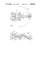
- FIGS. 1 and 2 illustrate plan and side views of a poultry harvester using rotor assemblies according to the present invention
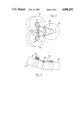
- FIGS. 3 and 4 show on a larger scale plan and side views of the rotor assembly used at the front end of the harvester
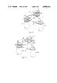
- FIGS. 5(a) and 5(b) show perspective views of the rotor assembly used at the rear end of the harvester (in two different modes of operation) and/or, in modified form, at the front end of the harvester;
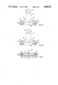
- FIGS. 6(a) and 6(b) show plan views of an alternative rotor configuration for use at the front end of the harvester and/or, in modified form, at the rear end of the harvester;
- FIG. 7 shows a side view of the rotor assembly of FIGS. 6(a) and 6(b);
- FIGS. 8(a) and 8(b) show schematic side and plan views of a modified rotor assembly for use at the rear of the harvester
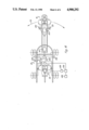
- FIG. 9 shows a detailed view of the preferred form of rotor used in the harvester pick-up head and discharge assembly.
- FIG. 10 shows, in purely diagrammatic fashion, the various drives etc. not included in FIG. 1.
- a mobile birdharvester 10 in accordance with the present invention comprises three rotors 12, 13, 14 mounted in a triangular formation to provide a pick-up head 16 at the front end of the harvester.
- Each of the rotors 12, 13, 14 provides an array of flexible rubber fingers of the sort currently used for plucking chicken carcasses.
- each finger comprises a smooth root portion (adjacent a supporting drum member) and a corrugated end portion.
- the fingers will taper from an initial diameter of about 25 mm to a final diameter of about 12 mm at the tip.
- the overall finger length is typically about 235 mm giving rise to an overlap of about 50 mm at the position of maximum intermesh between the two rotors.
- the resilient nature of the finger material allows the fingers to be pushed into appropriate apertures in the two drum members, a peripheral groove in the root portion of each finger ensuring that the finger locks securely into place in the drum aperture.
- the support frame for belt 18 is provided by a scanning arm 20 the upper end of which is pivotally mounted on the harvester chassis 22 to allow the arm to scan over an arc 23 and the lower end of which is optionally carried on pivotting ground-support wheels 120, 121.
- the conveyor 18 discharges on to a second conveyor 24 (omitted from FIG. 10) at the rear end of which is a 3-rotor discharge assembly 26.
- a second conveyor 24 (omitted from FIG. 10) at the rear end of which is a 3-rotor discharge assembly 26.
- This latter is of the same or essentially the same configuration and rotor design as pick-up head 16 except that the end rotor (114) now trails the other two rotors (112, 113) and all three rotors rotate about vertical axes.
- This last requirement distinguishes the discharge assembly from the pick-up head 16 which only the end rotor 14 rotates about a vertical axis and the other two rotors 12, 13 rotate about upwardly and forwardly inclines axes lying perpendicular to the support surface of inclined belt 18.
- the harvester 10 can be driven either forward or backwards, the drives on the harvester being mechanical, electrical, hydraulic or pneumatic, or any combination of these, as convenient, with the prime mover 125 being carried on the chassis 22.
- the scanning action of the arm 20 is effected by a reversible motor 127 either by rotationally driving the top end of the arm and/or, if preferred, by suitably driving its ground-support wheels 120, 121 (if present).
- a reversible motor 127 either by rotationally driving the top end of the arm and/or, if preferred, by suitably driving its ground-support wheels 120, 121 (if present).
- the arm 20 will engage one or other of two contact switches 129, 130 which operate through a direction control unit 132 to reverse the drives from motors 123, 127.
- unit 132 also operative on motor 123, the directions of rotation of the front rotor 14 and the scanning arm 20 can be kept the same as one another throughout the harvesting operation.
- a manual (override) control 133 may be included for activating unit 132 to reverse the directions of scan and front rotor rotation.
- the reversible motor 124 for powering discharge rotor 114 is also provided with a direction control unit 134 which determines the direction of rotation of the rotor at any given moment.
- a signal from the weigher 136 operates unit 134 to reverse the rotational direction of the motor 124 and discharge rotor 114. This, in turn, switches the discharge of birds from one side of the machine to the other.
- a manual control 138 may be used to activate direction control unit 134.
- the rotor pairs 12, 13 and 112, 113 have fixed directions of rotation (respectively inwardly and outwardly of the associated belt 18, 24) and end rotors 14, 114 are able to change direction (as shown by the double-headed arrows) so as to rotate in a contrary rotational sense to a chosen rotor of the rotor pairs 12, 13 and 112, 113.
- the broiler harvester 10 starts with the conveyors 18, 24 running and the various rotors rotating in the senses described.
- the pick-up head then scans through the birds with the front rotor 14 automatically rotating in the same direction as the direction of scan as hereinbefore described to lift the birds up from the litter and place them onto the conveyor 18.
- the birds are then carried along by the conveyor 18 until they are discharged onto the second conveyor 24, along which they continue to travel until they are removed by the discharge assembly 26 for packing into crates or modules (not shown) at the sides of the assembly.
- the direction control for rotor 114 is either manually operated or is automatically operated once a predetermined weight of birds has been discharged from the conveyor 24 (as detected by the continuous weigher 136 underneath the conveyor).
- the ability to discharge the birds to one or other side of belt 24 at allows the loaded crates on one side of the belt to be replaced by empty crates while the discharge continues uninterrupted to the crates at the other side of belt 24.
- the direction of rotation of the rotor front 14 is automatically reversed e.g. by an appropriate one of the contact switches 129, 130, and the harvester moves forward with the arm 20 scanning back in the reverse direction and the rotational sense of rotor 14 similarly reversed.
- the direction control units 132, 134 might comprise 3-way switches which can be activated (by the contact switches 129, 130, by the continuous weigher 136, or by the manual controls 133, 138, as the case may be) to reverse the polarity of their outputs to the reversible motors 123, 124 and 127.
- the end rotors 14, 114 may be driven in either direction from one or more reversible motors (not shown), mounted on the arm 20 e.g. the reversible motors 123, 124 of FIG. 10.
- the two associated rotors 12/13 and 112/113 are driven from rotor 14 and 114 by a belt and pulley drive 30, 31 through so-called sprag clutches present in both arrangements but only shown diagrammatically at 33, 34, in FIGS. 5(a) and 5(b).
- the sprag clutch like the freewheel mechanism on a bicycle, is automatically operative when called upon to transmit motion in a first rotational sense but is inoperative i.e. it "slips", when called upon to transmit motion in the reverse directional sense.
- the sprag clutch 34 is designed to transmit an anti-clockwise rotation of the belt-driven pulley 36 to upper pulley 37 of a second pulley belt system 38 and to freewheel for clockwise rotations of pulley 36.
- Sprag clutch 33 is designed to transmit a clockwise rotation of the driven pulley 39 to the upper pulley 40 of system 38 but to freewheel for anti-clockwise rotations of pulley 39.
- the end rotor 114 rotates anti-clockwise and the left-hand rotor 113 clockwise.
- it is sprag clutch 33 that drives the left-hand rotor 113 and sprag clutch 34 that freewheels.
- the sprag clutch 34 When discharging birds to the right-hand side as shown in FIG. 5(a), however, the sprag clutch 34 is operative and drives the right-hand side rotor 112 anti-clockwise, the left-hand rotor 113 being driven clockwise via the cross belt 41 with sprag clutch 33 inoperative so as to allow rotation of pulley 40 and rotor 113 in the contrary direction to pulley 37.
- FIGS. 6(a), 6(b) and 7 show an alternative belt arrangement to that shown in FIGS. 3 and 4, although for simplicity, the same reference numerals have been used to indicate parts playing an analogous or closely related role to the similarly numbered parts of the systems shown in the earlier Figures.
- reference numeral 50 indicates a reversible motor for driving the front rotor shaft 51.
- waisted support reels 43, 44 are required in the assemblies of FIGS. 3 and 4 and FIGS. 6(a), 6(b) and 7 due to the need to redirect the belt to suit the different inclinations of the rotor axes, these are only optional in the parallel axis assembly of FIGS. 5(a) and 5(b) where instead, as shown in these last two Figures, the drive pulley for rotor 114 can be slightly lower than pullies 36, 37 to prevent engagement of the crossing sections of the belt in drive system 31.
- V-belts may be used throughout, it is preferred to use circular-section belts instead e.g. 10 mm diameter Routhane round-section belts.
- FIGS. 8(a) and 8(b) show how the rearmost rotor 114 may be provided with a rubber conveyor disc 116 held in place by a rigid support disc 118 on the same axle as the rotor. In operation, the rubber disc 116 will rotate with the rotor 114 to assist in the conveying of the birds away from the discharge assembly 26.
Abstract
Description
Claims (11)
Applications Claiming Priority (2)
| Application Number | Priority Date | Filing Date | Title |
|---|---|---|---|
| GB8710610 | 1987-05-05 | ||
| GB878710610A GB8710610D0 (en) | 1987-05-05 | 1987-05-05 | Rotor assemblies |
Publications (1)
| Publication Number | Publication Date |
|---|---|
| US4900292A true US4900292A (en) | 1990-02-13 |
Family
ID=10616845
Family Applications (1)
| Application Number | Title | Priority Date | Filing Date |
|---|---|---|---|
| US07/190,141 Expired - Lifetime US4900292A (en) | 1987-05-05 | 1988-05-04 | Rotor assemblies |
Country Status (7)
| Country | Link |
|---|---|
| US (1) | US4900292A (en) |
| EP (1) | EP0290235B1 (en) |
| JP (1) | JPS63296638A (en) |
| CA (1) | CA1295854C (en) |
| DE (1) | DE3865078D1 (en) |
| ES (1) | ES2025776T3 (en) |
| GB (2) | GB8710610D0 (en) |
Cited By (40)
| Publication number | Priority date | Publication date | Assignee | Title |
|---|---|---|---|---|
| US5259811A (en) * | 1990-10-17 | 1993-11-09 | British Technology Group Ltd. | Poultry-handling assembly |
| US5325820A (en) * | 1992-10-14 | 1994-07-05 | American Calan, Inc. | Poultry harvester |
| US5361727A (en) * | 1991-10-17 | 1994-11-08 | British Technology Group Limited | Poultry harvester |
| US5450714A (en) * | 1994-10-07 | 1995-09-19 | Allied Products Corporation | Rotary cutter with counterrotation gearbox |
| US5592902A (en) * | 1994-11-21 | 1997-01-14 | The Taylor Group, Inc. | Method and apparatus for cooping chickens |
| US5669213A (en) * | 1995-11-03 | 1997-09-23 | Allied Products Corporation | Counterrotation mulching mower |
| US5706765A (en) * | 1994-11-21 | 1998-01-13 | The Taylor Group, Inc. | Method and apparatus for cooping chickens |
| US5809765A (en) * | 1997-03-17 | 1998-09-22 | Allied Products Corporation | Counterrotation mulching mower and blade assembly |
| US5983837A (en) * | 1996-11-21 | 1999-11-16 | American Calan, Inc. | Bird counter |
| US6612918B2 (en) | 2000-08-16 | 2003-09-02 | Bright Coop Co. | Poultry cage staging and filling method and apparatus |
| US20060200071A1 (en) * | 2005-02-14 | 2006-09-07 | Sterling Bernhard B | Method and apparatus for detection of multiple analytes |
| US20070083090A1 (en) * | 2005-10-06 | 2007-04-12 | Sterling Bernhard B | System and method for determining a treatment dose for a patient |
| US20080058135A1 (en) * | 2003-10-13 | 2008-03-06 | Varibox (Pty) Limited | Infinitely variable transmission |
| US20090157430A1 (en) * | 2007-10-11 | 2009-06-18 | Peter Rule | Synchronization and configuration of patient monitoring devices |
| US20100121170A1 (en) * | 2008-09-12 | 2010-05-13 | Optiscan Biomedical Corporation | Fluid component analysis system and method for glucose monitoring and control |
| US20100240964A1 (en) * | 2005-02-14 | 2010-09-23 | Sterling Bernhard B | System and method for determining a treatment dose for a patient |
| US7972296B2 (en) | 2007-10-10 | 2011-07-05 | Optiscan Biomedical Corporation | Fluid component analysis system and method for glucose monitoring and control |
| US8597190B2 (en) | 2007-05-18 | 2013-12-03 | Optiscan Biomedical Corporation | Monitoring systems and methods with fast initialization |
| US11324889B2 (en) | 2020-02-14 | 2022-05-10 | Insulet Corporation | Compensation for missing readings from a glucose monitor in an automated insulin delivery system |
| US11386996B2 (en) | 2014-01-30 | 2022-07-12 | Insulet Netherlands B.V. | Therapeutic product delivery system and method of pairing |
| US11439754B1 (en) | 2021-12-01 | 2022-09-13 | Insulet Corporation | Optimizing embedded formulations for drug delivery |
| US11547800B2 (en) | 2020-02-12 | 2023-01-10 | Insulet Corporation | User parameter dependent cost function for personalized reduction of hypoglycemia and/or hyperglycemia in a closed loop artificial pancreas system |
| US11551802B2 (en) | 2020-02-11 | 2023-01-10 | Insulet Corporation | Early meal detection and calorie intake detection |
| US11565043B2 (en) | 2018-05-04 | 2023-01-31 | Insulet Corporation | Safety constraints for a control algorithm based drug delivery system |
| US11565039B2 (en) | 2018-10-11 | 2023-01-31 | Insulet Corporation | Event detection for drug delivery system |
| US11596740B2 (en) | 2015-02-18 | 2023-03-07 | Insulet Corporation | Fluid delivery and infusion devices, and methods of use thereof |
| US11607493B2 (en) | 2020-04-06 | 2023-03-21 | Insulet Corporation | Initial total daily insulin setting for user onboarding |
| US11628251B2 (en) | 2018-09-28 | 2023-04-18 | Insulet Corporation | Activity mode for artificial pancreas system |
| US11684716B2 (en) | 2020-07-31 | 2023-06-27 | Insulet Corporation | Techniques to reduce risk of occlusions in drug delivery systems |
| US11724027B2 (en) | 2016-09-23 | 2023-08-15 | Insulet Corporation | Fluid delivery device with sensor |
| US11738144B2 (en) | 2021-09-27 | 2023-08-29 | Insulet Corporation | Techniques enabling adaptation of parameters in aid systems by user input |
| US11801344B2 (en) | 2019-09-13 | 2023-10-31 | Insulet Corporation | Blood glucose rate of change modulation of meal and correction insulin bolus quantity |
| US11833329B2 (en) | 2019-12-20 | 2023-12-05 | Insulet Corporation | Techniques for improved automatic drug delivery performance using delivery tendencies from past delivery history and use patterns |
| US11857763B2 (en) | 2016-01-14 | 2024-01-02 | Insulet Corporation | Adjusting insulin delivery rates |
| US11865299B2 (en) | 2008-08-20 | 2024-01-09 | Insulet Corporation | Infusion pump systems and methods |
| US11904140B2 (en) | 2021-03-10 | 2024-02-20 | Insulet Corporation | Adaptable asymmetric medicament cost component in a control system for medicament delivery |
| US11929158B2 (en) | 2016-01-13 | 2024-03-12 | Insulet Corporation | User interface for diabetes management system |
| US11935637B2 (en) | 2019-09-27 | 2024-03-19 | Insulet Corporation | Onboarding and total daily insulin adaptivity |
| USD1020794S1 (en) | 2018-04-02 | 2024-04-02 | Bigfoot Biomedical, Inc. | Medication delivery device with icons |
| US11957875B2 (en) | 2020-12-04 | 2024-04-16 | Insulet Corporation | Techniques and devices providing adaptivity and personalization in diabetes treatment |
Families Citing this family (1)
| Publication number | Priority date | Publication date | Assignee | Title |
|---|---|---|---|---|
| DE102016103204A1 (en) * | 2016-02-24 | 2017-08-24 | Claas Selbstfahrende Erntemaschinen Gmbh | Drive arrangement for a combine harvester |
Citations (6)
| Publication number | Priority date | Publication date | Assignee | Title |
|---|---|---|---|---|
| US2235619A (en) * | 1939-12-13 | 1941-03-18 | Eddy E Mcmahan | Mechanical poultry picker |
| US3235904A (en) * | 1964-03-20 | 1966-02-22 | Gainesville Machine Company In | Picking machine with multiple finger action |
| US4282632A (en) * | 1979-11-09 | 1981-08-11 | Conaway Everett T | Poultry pinning and de-hairing machine |
| GB2128870A (en) * | 1982-10-29 | 1984-05-10 | Nat Res Dev | Poultry-harvesting assembly |
| GB2138763A (en) * | 1983-04-29 | 1984-10-31 | Nat Res Dev | Poultry-harvesting assembly |
| US4508062A (en) * | 1982-10-29 | 1985-04-02 | National Research Development Corporation | Poultry-harvesting assembly |
-
1987
- 1987-05-05 GB GB878710610A patent/GB8710610D0/en active Pending
-
1988
- 1988-05-02 JP JP63109843A patent/JPS63296638A/en active Pending
- 1988-05-04 US US07/190,141 patent/US4900292A/en not_active Expired - Lifetime
- 1988-05-04 EP EP88304027A patent/EP0290235B1/en not_active Expired
- 1988-05-04 DE DE8888304027T patent/DE3865078D1/en not_active Expired - Lifetime
- 1988-05-04 CA CA000565867A patent/CA1295854C/en not_active Expired - Lifetime
- 1988-05-04 ES ES198888304027T patent/ES2025776T3/en not_active Expired - Lifetime
- 1988-05-04 GB GB8810476A patent/GB2205917B/en not_active Expired - Fee Related
Patent Citations (7)
| Publication number | Priority date | Publication date | Assignee | Title |
|---|---|---|---|---|
| US2235619A (en) * | 1939-12-13 | 1941-03-18 | Eddy E Mcmahan | Mechanical poultry picker |
| US3235904A (en) * | 1964-03-20 | 1966-02-22 | Gainesville Machine Company In | Picking machine with multiple finger action |
| US4282632A (en) * | 1979-11-09 | 1981-08-11 | Conaway Everett T | Poultry pinning and de-hairing machine |
| GB2128870A (en) * | 1982-10-29 | 1984-05-10 | Nat Res Dev | Poultry-harvesting assembly |
| US4508062A (en) * | 1982-10-29 | 1985-04-02 | National Research Development Corporation | Poultry-harvesting assembly |
| GB2138763A (en) * | 1983-04-29 | 1984-10-31 | Nat Res Dev | Poultry-harvesting assembly |
| US4513689A (en) * | 1983-04-29 | 1985-04-30 | National Research Development Corporation | Poultry-harvesting assembly |
Cited By (52)
| Publication number | Priority date | Publication date | Assignee | Title |
|---|---|---|---|---|
| US5259811A (en) * | 1990-10-17 | 1993-11-09 | British Technology Group Ltd. | Poultry-handling assembly |
| US5361727A (en) * | 1991-10-17 | 1994-11-08 | British Technology Group Limited | Poultry harvester |
| US5325820A (en) * | 1992-10-14 | 1994-07-05 | American Calan, Inc. | Poultry harvester |
| US5450714A (en) * | 1994-10-07 | 1995-09-19 | Allied Products Corporation | Rotary cutter with counterrotation gearbox |
| US5626007A (en) * | 1994-10-07 | 1997-05-06 | Allied Products Corporation | Rotary cutter with reversible counterrotation gearbox |
| US5592902A (en) * | 1994-11-21 | 1997-01-14 | The Taylor Group, Inc. | Method and apparatus for cooping chickens |
| US5706765A (en) * | 1994-11-21 | 1998-01-13 | The Taylor Group, Inc. | Method and apparatus for cooping chickens |
| US5669213A (en) * | 1995-11-03 | 1997-09-23 | Allied Products Corporation | Counterrotation mulching mower |
| US5983837A (en) * | 1996-11-21 | 1999-11-16 | American Calan, Inc. | Bird counter |
| US5809765A (en) * | 1997-03-17 | 1998-09-22 | Allied Products Corporation | Counterrotation mulching mower and blade assembly |
| US6612918B2 (en) | 2000-08-16 | 2003-09-02 | Bright Coop Co. | Poultry cage staging and filling method and apparatus |
| US20080058135A1 (en) * | 2003-10-13 | 2008-03-06 | Varibox (Pty) Limited | Infinitely variable transmission |
| US7713153B2 (en) * | 2003-10-13 | 2010-05-11 | Varibox Ip (Pty) Limited | Infinitely variable transmission |
| US20060200071A1 (en) * | 2005-02-14 | 2006-09-07 | Sterling Bernhard B | Method and apparatus for detection of multiple analytes |
| US9913604B2 (en) | 2005-02-14 | 2018-03-13 | Optiscan Biomedical Corporation | Analyte detection systems and methods using multiple measurements |
| US7722537B2 (en) | 2005-02-14 | 2010-05-25 | Optiscan Biomedical Corp. | Method and apparatus for detection of multiple analytes |
| US20100234703A1 (en) * | 2005-02-14 | 2010-09-16 | Sterling Bernhard B | Method and apparatus for detection of multiple analytes |
| US20100240964A1 (en) * | 2005-02-14 | 2010-09-23 | Sterling Bernhard B | System and method for determining a treatment dose for a patient |
| US8251907B2 (en) | 2005-02-14 | 2012-08-28 | Optiscan Biomedical Corporation | System and method for determining a treatment dose for a patient |
| US8140140B2 (en) | 2005-02-14 | 2012-03-20 | Optiscan Biomedical Corporation | Analyte detection system for multiple analytes |
| US20070083090A1 (en) * | 2005-10-06 | 2007-04-12 | Sterling Bernhard B | System and method for determining a treatment dose for a patient |
| US7785258B2 (en) | 2005-10-06 | 2010-08-31 | Optiscan Biomedical Corporation | System and method for determining a treatment dose for a patient |
| US8597190B2 (en) | 2007-05-18 | 2013-12-03 | Optiscan Biomedical Corporation | Monitoring systems and methods with fast initialization |
| US8449524B2 (en) | 2007-10-10 | 2013-05-28 | Optiscan Biomedical Corporation | Fluid component analysis systems and methods for glucose monitoring and control |
| US7972296B2 (en) | 2007-10-10 | 2011-07-05 | Optiscan Biomedical Corporation | Fluid component analysis system and method for glucose monitoring and control |
| US9414782B2 (en) | 2007-10-10 | 2016-08-16 | Optiscan Biomedical Corporation | Fluid component analysis systems and methods for glucose monitoring and control |
| US20090157430A1 (en) * | 2007-10-11 | 2009-06-18 | Peter Rule | Synchronization and configuration of patient monitoring devices |
| US11865299B2 (en) | 2008-08-20 | 2024-01-09 | Insulet Corporation | Infusion pump systems and methods |
| US20100121170A1 (en) * | 2008-09-12 | 2010-05-13 | Optiscan Biomedical Corporation | Fluid component analysis system and method for glucose monitoring and control |
| US9302045B2 (en) | 2008-09-12 | 2016-04-05 | Optiscan Biomedical Corporation | Fluid component analysis system and method for glucose monitoring and control |
| US8417311B2 (en) | 2008-09-12 | 2013-04-09 | Optiscan Biomedical Corporation | Fluid component analysis system and method for glucose monitoring and control |
| US11386996B2 (en) | 2014-01-30 | 2022-07-12 | Insulet Netherlands B.V. | Therapeutic product delivery system and method of pairing |
| US11596740B2 (en) | 2015-02-18 | 2023-03-07 | Insulet Corporation | Fluid delivery and infusion devices, and methods of use thereof |
| US11929158B2 (en) | 2016-01-13 | 2024-03-12 | Insulet Corporation | User interface for diabetes management system |
| US11857763B2 (en) | 2016-01-14 | 2024-01-02 | Insulet Corporation | Adjusting insulin delivery rates |
| US11724027B2 (en) | 2016-09-23 | 2023-08-15 | Insulet Corporation | Fluid delivery device with sensor |
| USD1020794S1 (en) | 2018-04-02 | 2024-04-02 | Bigfoot Biomedical, Inc. | Medication delivery device with icons |
| US11565043B2 (en) | 2018-05-04 | 2023-01-31 | Insulet Corporation | Safety constraints for a control algorithm based drug delivery system |
| US11628251B2 (en) | 2018-09-28 | 2023-04-18 | Insulet Corporation | Activity mode for artificial pancreas system |
| US11565039B2 (en) | 2018-10-11 | 2023-01-31 | Insulet Corporation | Event detection for drug delivery system |
| US11801344B2 (en) | 2019-09-13 | 2023-10-31 | Insulet Corporation | Blood glucose rate of change modulation of meal and correction insulin bolus quantity |
| US11935637B2 (en) | 2019-09-27 | 2024-03-19 | Insulet Corporation | Onboarding and total daily insulin adaptivity |
| US11833329B2 (en) | 2019-12-20 | 2023-12-05 | Insulet Corporation | Techniques for improved automatic drug delivery performance using delivery tendencies from past delivery history and use patterns |
| US11551802B2 (en) | 2020-02-11 | 2023-01-10 | Insulet Corporation | Early meal detection and calorie intake detection |
| US11547800B2 (en) | 2020-02-12 | 2023-01-10 | Insulet Corporation | User parameter dependent cost function for personalized reduction of hypoglycemia and/or hyperglycemia in a closed loop artificial pancreas system |
| US11324889B2 (en) | 2020-02-14 | 2022-05-10 | Insulet Corporation | Compensation for missing readings from a glucose monitor in an automated insulin delivery system |
| US11607493B2 (en) | 2020-04-06 | 2023-03-21 | Insulet Corporation | Initial total daily insulin setting for user onboarding |
| US11684716B2 (en) | 2020-07-31 | 2023-06-27 | Insulet Corporation | Techniques to reduce risk of occlusions in drug delivery systems |
| US11957875B2 (en) | 2020-12-04 | 2024-04-16 | Insulet Corporation | Techniques and devices providing adaptivity and personalization in diabetes treatment |
| US11904140B2 (en) | 2021-03-10 | 2024-02-20 | Insulet Corporation | Adaptable asymmetric medicament cost component in a control system for medicament delivery |
| US11738144B2 (en) | 2021-09-27 | 2023-08-29 | Insulet Corporation | Techniques enabling adaptation of parameters in aid systems by user input |
| US11439754B1 (en) | 2021-12-01 | 2022-09-13 | Insulet Corporation | Optimizing embedded formulations for drug delivery |
Also Published As
| Publication number | Publication date |
|---|---|
| GB8710610D0 (en) | 1987-06-10 |
| EP0290235A2 (en) | 1988-11-09 |
| GB8810476D0 (en) | 1988-06-08 |
| DE3865078D1 (en) | 1991-10-31 |
| ES2025776T3 (en) | 1992-04-01 |
| JPS63296638A (en) | 1988-12-02 |
| EP0290235A3 (en) | 1989-02-22 |
| GB2205917B (en) | 1990-10-17 |
| CA1295854C (en) | 1992-02-18 |
| EP0290235B1 (en) | 1991-09-25 |
| GB2205917A (en) | 1988-12-21 |
Similar Documents
| Publication | Publication Date | Title |
|---|---|---|
| US4900292A (en) | Rotor assemblies | |
| EP0481800B1 (en) | Poultry-handling assembly | |
| JPH0338812B2 (en) | ||
| US4930530A (en) | Leaf loading method | |
| US4513689A (en) | Poultry-harvesting assembly | |
| US3118265A (en) | shaver | |
| US4162726A (en) | Sod harvesting machine having means for conveying and stacking sod pads | |
| CA1209347A (en) | Poultry-harvesting assembly | |
| US6701702B2 (en) | Machine for mowing stalk-like crop | |
| US3810444A (en) | Automatic animal dropping pit cleaner | |
| US4772173A (en) | Silo unloader | |
| JPH0697905B2 (en) | A grass self-supporting riding harvester | |
| US20050232737A1 (en) | Integrated pivot and conveyor drive shaft for an unloading door of a receiver of a cotton harvesting machine | |
| JPS6349160Y2 (en) | ||
| JP2528413Y2 (en) | Grain stalk transporter for all culms | |
| CA1111077A (en) | Sod harvesting machine having means for conveying and stacking sod pads | |
| JP2003304733A (en) | Combine harvester baler | |
| JPH0117980Y2 (en) | ||
| JP4085756B2 (en) | Combine | |
| JP3728434B2 (en) | Crop harvesting machine | |
| US222772A (en) | Improvement in combined reaper, thrasher, and separator | |
| JP3712480B2 (en) | Combine | |
| USRE20342E (en) | F macgregor | |
| SU1205815A1 (en) | Tracter semi-mounted stack mover | |
| JPS6131641Y2 (en) |
Legal Events
| Date | Code | Title | Description |
|---|---|---|---|
| AS | Assignment |
Owner name: NATIONAL RESEARCH DEVELOPMENT CORPORATION, ENGLAND Free format text: ASSIGNMENT OF ASSIGNORS INTEREST.;ASSIGNORS:BERRY, PAUL S.;FROST, DEREK J.;INSKIP, PETER F.;REEL/FRAME:005133/0788 Effective date: 19880428 |
|
| STCF | Information on status: patent grant |
Free format text: PATENTED CASE |
|
| CC | Certificate of correction | ||
| AS | Assignment |
Owner name: BRITISH TECHNOLOGY GROUP LIMITED, ENGLAND Free format text: ASSIGNMENT OF ASSIGNORS INTEREST.;ASSIGNOR:NATIONAL RESEARCH DEVELOPMENT CORPORATION;REEL/FRAME:006243/0136 Effective date: 19920709 |
|
| FEPP | Fee payment procedure |
Free format text: PAYOR NUMBER ASSIGNED (ORIGINAL EVENT CODE: ASPN); ENTITY STATUS OF PATENT OWNER: LARGE ENTITY |
|
| FPAY | Fee payment |
Year of fee payment: 4 |
|
| FPAY | Fee payment |
Year of fee payment: 8 |
|
| FEPP | Fee payment procedure |
Free format text: PAYER NUMBER DE-ASSIGNED (ORIGINAL EVENT CODE: RMPN); ENTITY STATUS OF PATENT OWNER: LARGE ENTITY Free format text: PAYOR NUMBER ASSIGNED (ORIGINAL EVENT CODE: ASPN); ENTITY STATUS OF PATENT OWNER: LARGE ENTITY |
|
| FPAY | Fee payment |
Year of fee payment: 12 |