US4984839A - Front glass moulding for vehicle - Google Patents
Front glass moulding for vehicle Download PDFInfo
- Publication number
- US4984839A US4984839A US07/204,525 US20452588A US4984839A US 4984839 A US4984839 A US 4984839A US 20452588 A US20452588 A US 20452588A US 4984839 A US4984839 A US 4984839A
- Authority
- US
- United States
- Prior art keywords
- moulding
- front glass
- glass pane
- side sections
- central section
- Prior art date
- Legal status (The legal status is an assumption and is not a legal conclusion. Google has not performed a legal analysis and makes no representation as to the accuracy of the status listed.)
- Expired - Fee Related
Links
- 238000000465 moulding Methods 0.000 title claims abstract description 141
- 239000011521 glass Substances 0.000 title claims abstract description 92
- 229920003002 synthetic resin Polymers 0.000 claims abstract description 17
- 239000000057 synthetic resin Substances 0.000 claims abstract description 17
- 230000014759 maintenance of location Effects 0.000 description 3
- 230000001154 acute effect Effects 0.000 description 2
- 238000005452 bending Methods 0.000 description 2
- 238000010438 heat treatment Methods 0.000 description 2
- 229920000728 polyester Polymers 0.000 description 2
- 239000000853 adhesive Substances 0.000 description 1
- 230000001070 adhesive effect Effects 0.000 description 1
- 230000000694 effects Effects 0.000 description 1
- 230000008030 elimination Effects 0.000 description 1
- 238000003379 elimination reaction Methods 0.000 description 1
- 238000004519 manufacturing process Methods 0.000 description 1
Images


Classifications
-
- B—PERFORMING OPERATIONS; TRANSPORTING
- B60—VEHICLES IN GENERAL
- B60J—WINDOWS, WINDSCREENS, NON-FIXED ROOFS, DOORS, OR SIMILAR DEVICES FOR VEHICLES; REMOVABLE EXTERNAL PROTECTIVE COVERINGS SPECIALLY ADAPTED FOR VEHICLES
- B60J1/00—Windows; Windscreens; Accessories therefor
- B60J1/20—Accessories, e.g. wind deflectors, blinds
- B60J1/2002—Wind deflectors specially adapted for preventing soiling, e.g. for side windows
-
- B—PERFORMING OPERATIONS; TRANSPORTING
- B60—VEHICLES IN GENERAL
- B60J—WINDOWS, WINDSCREENS, NON-FIXED ROOFS, DOORS, OR SIMILAR DEVICES FOR VEHICLES; REMOVABLE EXTERNAL PROTECTIVE COVERINGS SPECIALLY ADAPTED FOR VEHICLES
- B60J10/00—Sealing arrangements
- B60J10/20—Sealing arrangements characterised by the shape
- B60J10/22—Sealing arrangements characterised by the shape having varying cross-section in the longitudinal direction
-
- B—PERFORMING OPERATIONS; TRANSPORTING
- B60—VEHICLES IN GENERAL
- B60J—WINDOWS, WINDSCREENS, NON-FIXED ROOFS, DOORS, OR SIMILAR DEVICES FOR VEHICLES; REMOVABLE EXTERNAL PROTECTIVE COVERINGS SPECIALLY ADAPTED FOR VEHICLES
- B60J10/00—Sealing arrangements
- B60J10/20—Sealing arrangements characterised by the shape
- B60J10/23—Sealing arrangements characterised by the shape assembled from two or more parts
- B60J10/233—Modular sealing arrangements, i.e. arrangements built up from a large number of joined modules
-
- B—PERFORMING OPERATIONS; TRANSPORTING
- B60—VEHICLES IN GENERAL
- B60J—WINDOWS, WINDSCREENS, NON-FIXED ROOFS, DOORS, OR SIMILAR DEVICES FOR VEHICLES; REMOVABLE EXTERNAL PROTECTIVE COVERINGS SPECIALLY ADAPTED FOR VEHICLES
- B60J10/00—Sealing arrangements
- B60J10/20—Sealing arrangements characterised by the shape
- B60J10/23—Sealing arrangements characterised by the shape assembled from two or more parts
- B60J10/235—Sealing arrangements characterised by the shape assembled from two or more parts the parts being joined along their longitudinal direction
-
- B—PERFORMING OPERATIONS; TRANSPORTING
- B60—VEHICLES IN GENERAL
- B60J—WINDOWS, WINDSCREENS, NON-FIXED ROOFS, DOORS, OR SIMILAR DEVICES FOR VEHICLES; REMOVABLE EXTERNAL PROTECTIVE COVERINGS SPECIALLY ADAPTED FOR VEHICLES
- B60J10/00—Sealing arrangements
- B60J10/20—Sealing arrangements characterised by the shape
- B60J10/25—Sealing arrangements characterised by the shape characterised by water drainage means
-
- B—PERFORMING OPERATIONS; TRANSPORTING
- B60—VEHICLES IN GENERAL
- B60J—WINDOWS, WINDSCREENS, NON-FIXED ROOFS, DOORS, OR SIMILAR DEVICES FOR VEHICLES; REMOVABLE EXTERNAL PROTECTIVE COVERINGS SPECIALLY ADAPTED FOR VEHICLES
- B60J10/00—Sealing arrangements
- B60J10/70—Sealing arrangements specially adapted for windows or windscreens
Definitions
- This invention relates to a front glass moulding for use in a vehicle such as an automobile between the body panel and the front glass pane in the front portion of the vehicle, and more particularly to such a front glass moulding which comprises an integrally moulded body which includes a substantially U-shaped main moulding portion having a central section for receiving a glass pane and two side sections extending at substantially right angles to the central section for receiving the glass pane and guiding rainwater.
- Auxiliary moulding portions are adapted to be received in the side sections of the main moulding portion to form rainwater guides in cooperation with the side sections.
- the prior art front glass mouldings generally comprise a central section having a groove for receiving the leading edge of a front glass pane and side sections formed separately from the central sections and having lower grooves for receiving the side edges of the glass pane and upper grooves for guiding rainwater to prevent rainwater from scattering and invading into the cab of the vehicle.
- the side sections having the upper and lower grooves cannot be employed with a central section having a single groove, since the central section and side sections have to be connected together by means of separate corner joints.
- the prior art front glass mouldings are formed by three different types of components. Further, the use of the corner joints degrades the external appearance of the front portion of the vehicle.
- the glass pane can be easily and positively held in position in the front glass moulding to thereby enhance the operation manufacturing the front glass moulding and mounting the front glass pane. Further, the elimination of the corner joints gives an aesthetic external appearance to the front portion of the vehicle.
- a front glass moulding for a vehicle comprising a substantially U-shaped synthetic resin main moulding portion having a wide head and a leg extending downwardly from the head at substantially right angles thereto. Included is a central section for receiving a front glass pane and side sections extending from the opposite ends of the central section at substantially right angles to the central section for receiving the glass pane and guiding rainwater.
- Synthetic resin auxiliary moulding portions are received in the side sections of the main moulding portion, wherein the head in the central section defines a recess for receiving the front glass pane, the legs of the side sections are each provided with on one surface at least one engaging means to pinch the front glass pane in cooperation with the associated auxiliary moulding portion, and the auxiliary moulding portions are each inwardly curved on their inner surface to form a rainwater guiding groove.
- FIG. 1 is a perspective view of a vehicle on which a front glass moulding of the present invention is mounted;
- FIG. 2 is a fragmentary perspective view of a preform for a main moulding portion of a first embodiment of the front glass moulding according to the present invention
- FIG. 3 is a perspective view of an auxiliary moulding portion of the front glass moulding
- FIG. 4 is a cross-sectional view on an enlarged scale taken substantially along line A--A of FIG. 1;
- FIG. 5 is a cross-sectional view on an enlarged scale taken substantially along line B--B of FIG. 2;
- FIG. 6 is a fragmentary perspective view of a preform of a second embodiment of the front glass moulding of the present invention.
- FIG. 7 is a perspective view of an auxiliary moulding portion of the second embodiment of the front glass moulding of the invention.
- FIG. 8 is a cross-sectional view taken substantially along line A--A of FIG. 1;
- FIG. 9 is a cross-sectional view taken substantially along line B--B of FIG. 1;
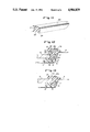
- FIG. 10 is a fragmentary perspective view of a preform of a third embodiment of the front glass moulding according to the present invention.
- FIG. 11 is a perspective view of an auxiliary moulding portion of the third embodiment of the front glass moulding
- FIG. 12 is a cross-sectional view taken substantially along line A--A of FIG. 1;
- FIG. 13 is a cross-sectional view taken substantially along line B--B of FIG. 1.
- FIG. 2 a section of a preform for the first embodiment of the front glass moulding of the present invention is generally shown by reference numeral 10 and comprises a body 11 integrally moulded by extruding a suitable synthetic resin.
- the body 11 is in the form of an elongated strip of a selected length and has a wide head 12, which is adapted to be exposed, and a leg 13 extending downwardly from the head at substantially right angles thereto, which is adapted to be positioned within a panel P of a vehicle V.
- One, or the inner, surface of the leg 13 is provided with a recess 14 in a position right below the under surface of the head 12 to define a shoulder or engaging means 15.
- the lower end of the leg 13 is inwardly bent in a curve to provide a projection or lower engaging means 16.
- the other, or outer, surface of the leg 13 is provided with at least one retention projection 17 (two vertically spaced projections 17 are in the illustrated embodiment).
- a plurality of through holes 18 extend across the width of the leg 13 between the head 12 and the upper projection 17. The through holes are arranged in a spaced relationship in the longitudinal direction of the body 11.
- the body 11 is bent into a substantially U-shaped configuration under heating to provide a central section 11a and two side sections 11b extending from the opposite ends of the central section 11a at substantially right angles thereto.
- the leg 13 in the central section 11a is cut along a cutting line 19 to remove the portion of the leg 13 positioned below the engaging means 15 from the leg 13 in the central section 11a, in order to provide the main moulding portion of the front glass moulding.
- the body 11 may be formed without the portion of the leg 13 in the central section 11a that corresponds to the portion positioned below the engaging means 15 on the leg 13 in the central section 11a within the scope of the present invention. It is also contemplated that the portion of the leg 13 positioned below the engaging means 15 on the leg 13 in the section of the body where the central section 11a is expected to be formed is cut away prior to the bending of the body 11.
- FIG. 3 denotes one of two auxiliary moulding portions which form the first embodiment of the front glass moulding in cooperation with the above-mentioned main moulding portion. Since the two auxiliary moulding portions are identical with each other, only one of the auxiliary moulding portions will be described, with the understanding that the same description is applicable to the other auxiliary moulding portion.
- the auxiliary moulding portion is in the form of an elongated strip formed by extruding a suitable synthetic resin and is shown by reference numeral 20.
- the inner surface of the auxiliary moulding portion 20 is inwardly curved to provide a rainwater guide groove 21 and the outer surface of the auxiliary moulding portion 20 is formed with a plurality of longitudinally spaced projections 22 to be fitted into the through holes 18 in the leg 13 of the associated moulding side section 11b.
- the under surface 23 of the auxiliary moulding portion 20 is stepped to provide a shoulder 24 at the rear side edge, adapted to seat on the shoulder or engaging means 15 on the leg 13 in the associated moulding side section 11b.
- Each auxiliary moulding portion 20 is positioned within the associated side section 11b by inserting the projections 22 on the auxiliary moulding portion 20 into the corresponding through holes 18 in the leg 13 of the side section 11b, whereupon the shoulder 24 on the auxiliary moulding portion 20 seats on the shoulder 15 to complete the front glass moulding.
- the under surface of the head 12 and the upper surface of the upper shoulder 15 in the central section 11a define a groove for receiving the upper or leading side edge of the front glass pane G of the vehicle V, as seen in FIG. 4.
- the surface of the shoulder or engaging means 15 and the upper side edge of the lower shoulder or engaging means 16 define a groove for receiving the side edge of the associated front glass pane G, as seen in FIG. 5.
- the inwardly curved inner face of the auxiliary moulding portion 20 associated with each side section 11b serves as a rainwater guide.
- the front glass moulding of the present invention eliminates the requirement of corner joints between the central section 11a and side sections 11b, and presents a very aesthetic external appearance.
- the one, or the inner, surface of the leg 13 of each side section 11b is formed with a rainwater guide groove in an upper portion thereof and a glass receiving groove in a lower portion thereof, the upper edge of the front glass pane G can be held in position in a stabilized condition in the central section 11a.
- the auxiliary moulding portion By merely fitting the auxiliary moulding portion into the associated side moulding section 11b by a selected or desired degree, the depth of the rainwater guide can be selectively varied and the under surface of the auxiliary moulding portion can positively hold the side edge of the front glass pane G.
- the projections 22 on the auxiliary moulding portion 20 into the through holes 18 in the leg 13 of the associated side section 11a, the main moulding portion and the auxiliary moulding portion are connected.
- the moulding requires only two different types of parts, that is, the main moulding portion and the auxiliary moulding portions.
- the front glass moulding can be simply and easily assembled at less expense.
- the main moulding portion concurrently serves to hold the front glass pane and guide rainwater.
- the auxiliary moulding portions which serve to firmly pinch the front glass pane and adjust the depth of the rainwater guide grooves. The glass pane can thereby be positively held in position, and rainwater in varying amounts can be handled.
- the front glass pane G is inserted into the thus formed front glass moulding by sliding the glass pane along the inner surfaces of the legs 13 of the side moulding sections 11b until the leading side edge of the glass pane abuts against the inner surface of the leg 13 of the central moulding section 11a.
- the projections 22 on the auxiliary moulding portions 20 are then adjustably inserted into the through holes 18 in the legs 13 of the side moulding sections 11b to hold the glass pane G against the lower shoulders or engaging means 16 on the legs 13.
- adhesive A is filled in the space left between the panel P, the front glass moulding and the glass pane G to firmly secure them together as shown in FIGS. 4 and 5.
- FIG. 6 shows a section of the preform for the second embodiment of the front glass moulding.
- the preform is generally shown by reference numeral 10, and comprises a body 11 integrally moulded by extruding a suitable synthetic resin.
- the body 11 is in the form of an elongated strip of a selected length and has a wide head 12 adapted to be exposed and a leg 13 extending downwardly from the head at substantially right angles thereto and adapted to be positioned within the panel P of the vehicle V.
- One, or the inner, surface of the leg 13 is inwardly bent in a curve at the lower end thereof to provide a shoulder or engaging means 16 to define a recess 14 for the purpose to be described hereinafter.
- the other, or outer, surface of the leg 13 is provided with at least one retention projection 17 (two vertically spaced projections 17 are in the illustrated embodiment).
- the body 11 is bent into a substantially U-shaped configuration to provide a central section 11a and two side sections 11b extending from the opposite ends of the central section 11a at substantially right angles to the central section 11a.
- the leg 13 in the central section 11a is cut along the cutting line 19 to remove the portion of the leg 13 positioned below the upper projection 17.
- the body 11 may be formed without the portion of the leg 13 in the central section 11a positioned below the upper projection 17 in the second embodiment of the front glass moulding within the scope of the present invention.
- the portion of the leg 13 positioned below the upper projection 17 on the leg 13 in the section of the body where the central section 11a is expected to be formed is previously cut away prior to the bending of the body 11. In either of these ways, can the main moulding portion for the third embodiment of the front glass moulding be formed.
- FIG. 7 shows one of the auxiliary moulding portions which form the second embodiment of the front glass moulding of the invention in cooperation with the main moulding portion. Since the two auxiliary moulding portions are identical with each other, only one of the auxiliary moulding portions will be described, with the understanding that the same description will be applicable to the other auxiliary moulding portion.
- the auxiliary moulding portion is in the form of an elongated strip formed by extruding a suitable synthetic resin, and is shown by reference numeral 20.
- the inner surface of the auxiliary moulding portion 20 is inwardly curved to provide a rainwater guide groove 21, and the under surface 23 of the auxiliary moulding portion 20 is formed flat.
- the flat under surface 23 of the auxiliary moulding portion 20 is adapted to pinch the adjacent side edge of the front glass pane G in cooperation with the shoulder or engaging means 16 on the leg 13 on the associated moulding side portion 11b to positively hold the glass pane G in position.
- the front glass pane G is inserted into the front glass moulding by sliding the opposite side edges of the pane along the inner surfaces of the legs 13 of the side sections 11b until the leading side edge of the pane G abuts against the inner surface of the leg 13 of the central section 11a.
- auxiliary moulding portions 20 are then inserted into the spaces defined by the under surfaces of the heads 12 of the side sections 11b and the upper surface of the glass pane G to firmly press the glass pane G against the shoulders or engaging means 16 on the legs 13 of the side sections 11b to thereby hold the glass pane in position.
- the operative effects provided by the second embodiment of the front glass moulding according to the present invention are substantially similar to those described in connection with the first embodiment hereinabove.
- the depth and height of the rainwater guide grooves can be varied by suitably modifying the dimensions of the auxiliary moulding portions 20 so that the second embodiment can be suitably applied to various types of vehicles.
- FIG. 10 shows a section of the preform for the third embodiment.
- the preform is generally shown by reference numeral 10 and comprises a body 11 integrally moulded by extruding a suitable synthetic resin.
- the body 11 is in the form of an elongated strip of a selected length and has a wide head 12 and a leg 13 extending downwardly from the head 12 at right angles thereto.
- One, or the inner, surface of the leg 13 is provided, in a position below the head 12, with a recess 14 to define a shoulder or engaging means 15.
- the lower end of the leg 13 is inwardly bent in a curve to define a second engaging means 16, which defines a groove 18 in cooperation with the first-mentioned projection or engaging means 15.
- the other, or outer, surface of the leg 13 is provided with at least one retention projection 17 (two vertically spaced projections 17 are shown in the illustrated embodiment).
- reference numeral 12 denotes an ornamental polyester tape embedded in the head 12.
- Reference numeral 19 denotes a cutting line along which the leg 13, in a portion of the body 11, is cut to remove the portion of the leg positioned below the projection 15, as described in connection with the foregoing embodiments.
- the body 11 is bent into a substantially U-shaped configuration under heating to provide a central section 11a and two side sections 11b extending from the opposite ends of the central section at substantially right angles thereto.
- the leg 13 in the central section 11a is cut along the cutting line 19 to remove the portion of the leg 13 of the central section 11a positioned below the cutting line 19.
- the leg 13 in the portion of the body 11 which is expected to form the central section may be previously cut along the cutting line 19 to remove the portion positioned below the projection 15 before the body 11 is bent. In either way can the main moulding portion of the third embodiment of the front glass moulding be formed.
- FIG. 11 shows one of two auxiliary moulding portions 20 which form the third embodiment of the front glass moulding in cooperation with the main moulding portion as shown in FIGS. 12 and 13.
- the auxiliary moulding portion 20 of FIG. 11 is in the form of an elongated strip formed by extruding a suitable synthetic resin.
- the inner surface of the auxiliary moulding portion 20 is inwardly curved to provide a rainwater guide groove 21 when positioned in the associated side moulding section 11b as will be described hereinafter.
- the under surface of the auxiliary moulding portion 20 is substantially flat, but is provided at the rear or outer side edge with an acute downwardly extending projection 24.
- a front glass pane G is received into the main moulding portion in the same manner as described in connection with the foregoing embodiments and the auxiliary moulding portions 11b are placed into the side sections 11b in the manner as described in connection with the foregoing embodiments, whereby the glass pane G is firmly pinched between the projection or engaging means 15 and the under surface of the head 12 in the central section 11a and between the projections 15 and 16 in the side sections 11b.
- the glass pane G can be more positively held in position.
- the ornamental polyester tape 12a embedded in the exposed head 12 gives an aesthetic external appearance to the front glass moulding.
- the third embodiment is mounted in the panel P of the vehicle V in the same manner as described in connection with the first embodiment.
Abstract
Description
Claims (11)
Applications Claiming Priority (1)
| Application Number | Priority Date | Filing Date | Title |
|---|---|---|---|
| GB8813125A GB2219338B (en) | 1988-06-03 | 1988-06-03 | Front glass or windscreen mouldings |
Publications (1)
| Publication Number | Publication Date |
|---|---|
| US4984839A true US4984839A (en) | 1991-01-15 |
Family
ID=10637996
Family Applications (1)
| Application Number | Title | Priority Date | Filing Date |
|---|---|---|---|
| US07/204,525 Expired - Fee Related US4984839A (en) | 1988-06-03 | 1988-06-09 | Front glass moulding for vehicle |
Country Status (4)
| Country | Link |
|---|---|
| US (1) | US4984839A (en) |
| DE (1) | DE3819822A1 (en) |
| FR (1) | FR2632575B1 (en) |
| GB (1) | GB2219338B (en) |
Cited By (37)
| Publication number | Priority date | Publication date | Assignee | Title |
|---|---|---|---|---|
| US5039157A (en) * | 1989-12-14 | 1991-08-13 | Tokai Kogyo Kabushiki Kaisha | Windshield molding |
| US5044684A (en) * | 1989-11-22 | 1991-09-03 | Tokai Kogyo Kabushiki Kaisha | Molding for windshield of automobile |
| US5094498A (en) * | 1990-05-16 | 1992-03-10 | Tokai Kogyo Kabushiki Kaisha | Molding unit for use with an automobile |
| US5114206A (en) * | 1989-10-30 | 1992-05-19 | Tokai Kogyo Kabushiki Kaisha | Mounting of window glass plate on vehicle body panel |
| US5139302A (en) * | 1990-07-19 | 1992-08-18 | Nissan Motor Co., Ltd. | Window molding for automotive vehicle |
| US5171051A (en) * | 1990-11-06 | 1992-12-15 | Tokai Kogyo Kabushiki Kaisha | Fastener for mounting strip-like member to automobile body |
| US5174624A (en) * | 1991-02-07 | 1992-12-29 | Tokai Kogyo Kabushiki Kaisha | Molding for use with an automobile and process for manufacturing the same |
| US5190338A (en) * | 1990-09-06 | 1993-03-02 | Tokai Kogyo Kabushiki Kaisha | Automobile windshield molding and method of producing the same |
| US5228738A (en) * | 1991-09-26 | 1993-07-20 | Tokiwa Chemical Industries, Co., Ltd. | Windshield glass molding for vehicles |
| US5310236A (en) * | 1989-10-18 | 1994-05-10 | Hashimoto Forming Industry Co., Ltd. | Molding member for automobile window plate |
| US5311711A (en) * | 1992-10-30 | 1994-05-17 | Standard Products Company | J-type window lace assemblies |
| EP0602320A1 (en) * | 1992-08-18 | 1994-06-22 | Tokai Kogyo Kabushiki Kaisha | A windshield molding for vehicles |
| US5344205A (en) * | 1990-11-07 | 1994-09-06 | Tokai Kogyo Kabushiki Kaisha | Automobile windshield molding |
| US5360251A (en) * | 1993-11-09 | 1994-11-01 | Nifco, Inc. | Flush mount molding member |
| US5389423A (en) * | 1991-05-31 | 1995-02-14 | Tokai Kogyo Kabushiki Kaisha | Windshield molding for vehicles |
| US5454614A (en) * | 1991-07-25 | 1995-10-03 | Tokai Kogyo Kabushiki Kaisha | Windshield molding for vehicles and the production method thereof |
| US5478132A (en) * | 1994-04-15 | 1995-12-26 | Gold; Peter | Auto window molding and method of manufacturing same at least partially in situ |
| US5527083A (en) * | 1993-03-11 | 1996-06-18 | Henniges Elastomer - U | Car-body window frame assembly |
| US5718470A (en) * | 1991-07-25 | 1998-02-17 | Tokai Kogyo Kabushiki Kaisha | Windshield molding for vehicles and the production method thereof |
| WO1999055547A1 (en) * | 1998-04-23 | 1999-11-04 | Richard Fritz Gmbh + Co. Kg | Window unit for mounting in a predefined opening of motor vehicles and such like |
| US6095586A (en) * | 1990-10-23 | 2000-08-01 | Tokai Kogyo Kabushiki Kaisha | Automobile windshield molding and the method of producing the same |
| US6196615B1 (en) | 1990-10-23 | 2001-03-06 | Tokai Kogyo Kabushiki Kaisha | Automobile windshield molding and the method of producing the same |
| US6231117B1 (en) * | 1998-07-31 | 2001-05-15 | Kinugawa Rubber Ind. Co., Ltd. | Automotive window molding with lip position adjustment |
| US6328368B1 (en) | 1999-04-23 | 2001-12-11 | Dorcas & Kalam Co. | Automotive windshield molding with adhesive and releasable film |
| USRE37737E1 (en) * | 1990-09-06 | 2002-06-11 | Tokai Kogyo Kabushiki Kaisha | Automobile windshield molding and method of producing the same |
| US6637164B2 (en) * | 2000-07-31 | 2003-10-28 | Asahi Glass Company, Limited | Vehicular resinous window and vehicular door panel |
| US6829868B1 (en) * | 2003-01-14 | 2004-12-14 | International Aluminum Corporation | Glazing pane installation |
| US20050006922A1 (en) * | 2003-05-15 | 2005-01-13 | Hashimoto Forming Industry Co., Ltd. | Vehicle window molding |
| US20050055910A1 (en) * | 2000-06-05 | 2005-03-17 | Grunst Kenneth D. | Methods and structures for sealing air gaps in a building |
| US20050104406A1 (en) * | 2002-01-22 | 2005-05-19 | Eddy Pennerath | Gasket seal for a fixed window which is solidly connected to the flanges of an opening and the production method thereof |
| US20080196353A1 (en) * | 2005-05-26 | 2008-08-21 | Saint-Gobain Glass France | Device For Fixing An Ornamental Profiled Section On A Shaped Band |
| US20100237644A1 (en) * | 2009-03-17 | 2010-09-23 | Pilkington Italia S.P.A. | Vehicle glazing having a trim mounted thereon |
| US20130086865A1 (en) * | 2011-10-11 | 2013-04-11 | James Schoonover | Window seal extruded weather strip |
| US20140306480A1 (en) * | 2013-04-11 | 2014-10-16 | Tokai Kogyo Co., Ltd. | Molded product |
| US20160129771A1 (en) * | 2014-11-05 | 2016-05-12 | Toyota Shatai Kabushiki Kaisha | Peripheral structure of windshield for vehicle |
| US20160185189A1 (en) * | 2013-08-01 | 2016-06-30 | Saint-Gobain Glass France | Glass pane having a profiled joint and trim, trim and production method for the glass pane |
| US20190145628A1 (en) * | 2017-11-15 | 2019-05-16 | Bsh Home Appliances Corporation | Glass on outside of range door |
Families Citing this family (13)
| Publication number | Priority date | Publication date | Assignee | Title |
|---|---|---|---|---|
| JPH0628910B2 (en) * | 1987-09-29 | 1994-04-20 | 橋本フォーミング工業株式会社 | Window molding manufacturing method |
| US5154471A (en) * | 1989-12-07 | 1992-10-13 | Hashimoto Forming Industry Co., Ltd. | Automobile window molding assembly |
| JPH0386815U (en) * | 1989-12-25 | 1991-09-03 | ||
| US5176420A (en) * | 1989-12-25 | 1993-01-05 | Tokiwa Chemical Industries Co., Ltd. | Molding for front glass for vehicle |
| JP2595126B2 (en) * | 1990-08-28 | 1997-03-26 | 東海興業株式会社 | Vehicle wind molding |
| US5174623A (en) * | 1990-09-06 | 1992-12-29 | Tokai Kogyo Kabushiki Kaisha | Automobile windshield molding |
| DE4115854A1 (en) * | 1990-11-19 | 1992-05-21 | Tokiwa Chem Ind Ltd | WINDSHIELD MOUNT FOR VEHICLES |
| JP2600511B2 (en) * | 1991-03-29 | 1997-04-16 | 橋本フォーミング工業株式会社 | Window molding and manufacturing method thereof |
| US5257450A (en) * | 1991-03-29 | 1993-11-02 | Hashimoto Forming Industry Co., Ltd. | Automobile windshield molding member and method of manufacturing the same |
| US5474218A (en) * | 1994-07-25 | 1995-12-12 | Chrysler Corporation | Article carrier |
| FR2792882B1 (en) * | 1999-04-30 | 2001-07-20 | Wagon Automotive Snc | DEVICE FOR SHUTTERING A HOUSING IN THE BODY OF A VEHICLE, WITH WATER PASSAGE |
| US6279983B1 (en) * | 2000-10-30 | 2001-08-28 | Creative Extruded Products, Inc. | Method of installing automotive window molding |
| EP3103665B1 (en) * | 2015-06-09 | 2019-07-24 | Elkamet Kunststofftechnik GmbH | Profile strip, system and method for production of a profile strip |
Citations (23)
| Publication number | Priority date | Publication date | Assignee | Title |
|---|---|---|---|---|
| US2205538A (en) * | 1938-04-22 | 1940-06-25 | Pittsburgh Plate Glass Co | Window construction |
| GB703873A (en) * | 1951-09-06 | 1954-02-10 | Windshields Of Worcester Ltd | Improved means for glazing vehicle and other windows |
| US3583757A (en) * | 1967-10-20 | 1971-06-08 | Daimler Benz Ag | Installation for reducing the soiling of side windows in motor vehicles |
| US4088366A (en) * | 1975-08-02 | 1978-05-09 | Daimler-Benz Aktiengesellschaft | Bar projecting from windshield column of a motor vehicle |
| JPS5744088A (en) * | 1980-08-27 | 1982-03-12 | Isuzu Motors Ltd | Mounting of window glass |
| US4349994A (en) * | 1979-11-19 | 1982-09-21 | Aisin Seiki Kabushiki Kaisha | Weather strip assembly for vehicle window |
| US4358917A (en) * | 1981-05-11 | 1982-11-16 | Chrysler Corporation | Self-adjustable window molding for retaining glass |
| DE3210106A1 (en) * | 1982-03-19 | 1983-10-06 | Daimler Benz Ag | Window for vehicles, in particular for motor vehicles, attached by means of a bonding connection |
| JPS5912714A (en) * | 1982-07-13 | 1984-01-23 | Koji Niwayama | Filter apparatus |
| US4441775A (en) * | 1982-08-09 | 1984-04-10 | Automation Industries, Inc. | Coupling and decoupling aid for an electrical connector |
| EP0117816A2 (en) * | 1983-02-28 | 1984-09-05 | Saint Gobain Vitrage International | Mounting of a glass pane in an opening by glueing with maintenance of a spacing between pane and opening |
| JPS601002A (en) * | 1983-06-15 | 1985-01-07 | Bridgestone Corp | Wheel for vehicle |
| US4523783A (en) * | 1982-11-27 | 1985-06-18 | Yoshiyasu Yamada | Window mould |
| JPS60146716A (en) * | 1984-01-07 | 1985-08-02 | Kinugawa Rubber Ind Co Ltd | Setting structure for corner joint in car-mount molding |
| EP0157281A2 (en) * | 1984-03-31 | 1985-10-09 | Nishikawa Rubber Co., Ltd. | Motor vehicle window molding |
| JPS6112423A (en) * | 1984-06-27 | 1986-01-20 | Kinugawa Rubber Ind Co Ltd | Window molding for car |
| US4627145A (en) * | 1983-05-20 | 1986-12-09 | Draftex Industries Limited | Window glass mounting arrangements |
| US4712826A (en) * | 1985-12-28 | 1987-12-15 | Nissan Motor Co., Ltd. | Automotive window and molding assembly having a device for mounting a corner joint |
| US4757659A (en) * | 1986-12-04 | 1988-07-19 | Tokiwa Chemical Industries Co., Ltd. | Front glass mouldings |
| US4757660A (en) * | 1986-12-04 | 1988-07-19 | Tokiwa Chemical Industries Co., Ltd. | Front glass mouldings |
| US4765673A (en) * | 1987-05-04 | 1988-08-23 | General Motors Corporation | Windshield reveal molding |
| US4787187A (en) * | 1986-08-28 | 1988-11-29 | General Motors Corporation | Window trim strip |
| US4805363A (en) * | 1988-05-17 | 1989-02-21 | Peter Gold | Window retention system for automotive vehicles |
Family Cites Families (2)
| Publication number | Priority date | Publication date | Assignee | Title |
|---|---|---|---|---|
| JPH0239846Y2 (en) * | 1984-12-19 | 1990-10-25 | ||
| FR2600017A1 (en) * | 1986-06-12 | 1987-12-18 | Profil | SURROUNDING OF GLUED GLASS AND IN PARTICULAR FIXED GLASS OF MOTOR VEHICLE |
-
1988
- 1988-06-03 GB GB8813125A patent/GB2219338B/en not_active Expired - Fee Related
- 1988-06-08 DE DE3819822A patent/DE3819822A1/en active Granted
- 1988-06-09 US US07/204,525 patent/US4984839A/en not_active Expired - Fee Related
- 1988-06-14 FR FR888807936A patent/FR2632575B1/en not_active Expired - Fee Related
Patent Citations (23)
| Publication number | Priority date | Publication date | Assignee | Title |
|---|---|---|---|---|
| US2205538A (en) * | 1938-04-22 | 1940-06-25 | Pittsburgh Plate Glass Co | Window construction |
| GB703873A (en) * | 1951-09-06 | 1954-02-10 | Windshields Of Worcester Ltd | Improved means for glazing vehicle and other windows |
| US3583757A (en) * | 1967-10-20 | 1971-06-08 | Daimler Benz Ag | Installation for reducing the soiling of side windows in motor vehicles |
| US4088366A (en) * | 1975-08-02 | 1978-05-09 | Daimler-Benz Aktiengesellschaft | Bar projecting from windshield column of a motor vehicle |
| US4349994A (en) * | 1979-11-19 | 1982-09-21 | Aisin Seiki Kabushiki Kaisha | Weather strip assembly for vehicle window |
| JPS5744088A (en) * | 1980-08-27 | 1982-03-12 | Isuzu Motors Ltd | Mounting of window glass |
| US4358917A (en) * | 1981-05-11 | 1982-11-16 | Chrysler Corporation | Self-adjustable window molding for retaining glass |
| DE3210106A1 (en) * | 1982-03-19 | 1983-10-06 | Daimler Benz Ag | Window for vehicles, in particular for motor vehicles, attached by means of a bonding connection |
| JPS5912714A (en) * | 1982-07-13 | 1984-01-23 | Koji Niwayama | Filter apparatus |
| US4441775A (en) * | 1982-08-09 | 1984-04-10 | Automation Industries, Inc. | Coupling and decoupling aid for an electrical connector |
| US4523783A (en) * | 1982-11-27 | 1985-06-18 | Yoshiyasu Yamada | Window mould |
| EP0117816A2 (en) * | 1983-02-28 | 1984-09-05 | Saint Gobain Vitrage International | Mounting of a glass pane in an opening by glueing with maintenance of a spacing between pane and opening |
| US4627145A (en) * | 1983-05-20 | 1986-12-09 | Draftex Industries Limited | Window glass mounting arrangements |
| JPS601002A (en) * | 1983-06-15 | 1985-01-07 | Bridgestone Corp | Wheel for vehicle |
| JPS60146716A (en) * | 1984-01-07 | 1985-08-02 | Kinugawa Rubber Ind Co Ltd | Setting structure for corner joint in car-mount molding |
| EP0157281A2 (en) * | 1984-03-31 | 1985-10-09 | Nishikawa Rubber Co., Ltd. | Motor vehicle window molding |
| JPS6112423A (en) * | 1984-06-27 | 1986-01-20 | Kinugawa Rubber Ind Co Ltd | Window molding for car |
| US4712826A (en) * | 1985-12-28 | 1987-12-15 | Nissan Motor Co., Ltd. | Automotive window and molding assembly having a device for mounting a corner joint |
| US4787187A (en) * | 1986-08-28 | 1988-11-29 | General Motors Corporation | Window trim strip |
| US4757659A (en) * | 1986-12-04 | 1988-07-19 | Tokiwa Chemical Industries Co., Ltd. | Front glass mouldings |
| US4757660A (en) * | 1986-12-04 | 1988-07-19 | Tokiwa Chemical Industries Co., Ltd. | Front glass mouldings |
| US4765673A (en) * | 1987-05-04 | 1988-08-23 | General Motors Corporation | Windshield reveal molding |
| US4805363A (en) * | 1988-05-17 | 1989-02-21 | Peter Gold | Window retention system for automotive vehicles |
Cited By (47)
| Publication number | Priority date | Publication date | Assignee | Title |
|---|---|---|---|---|
| US5310236A (en) * | 1989-10-18 | 1994-05-10 | Hashimoto Forming Industry Co., Ltd. | Molding member for automobile window plate |
| US5114206A (en) * | 1989-10-30 | 1992-05-19 | Tokai Kogyo Kabushiki Kaisha | Mounting of window glass plate on vehicle body panel |
| US5044684A (en) * | 1989-11-22 | 1991-09-03 | Tokai Kogyo Kabushiki Kaisha | Molding for windshield of automobile |
| US5039157A (en) * | 1989-12-14 | 1991-08-13 | Tokai Kogyo Kabushiki Kaisha | Windshield molding |
| US5094498A (en) * | 1990-05-16 | 1992-03-10 | Tokai Kogyo Kabushiki Kaisha | Molding unit for use with an automobile |
| US5139302A (en) * | 1990-07-19 | 1992-08-18 | Nissan Motor Co., Ltd. | Window molding for automotive vehicle |
| USRE37737E1 (en) * | 1990-09-06 | 2002-06-11 | Tokai Kogyo Kabushiki Kaisha | Automobile windshield molding and method of producing the same |
| US5190338A (en) * | 1990-09-06 | 1993-03-02 | Tokai Kogyo Kabushiki Kaisha | Automobile windshield molding and method of producing the same |
| US6196615B1 (en) | 1990-10-23 | 2001-03-06 | Tokai Kogyo Kabushiki Kaisha | Automobile windshield molding and the method of producing the same |
| US6095586A (en) * | 1990-10-23 | 2000-08-01 | Tokai Kogyo Kabushiki Kaisha | Automobile windshield molding and the method of producing the same |
| US5171051A (en) * | 1990-11-06 | 1992-12-15 | Tokai Kogyo Kabushiki Kaisha | Fastener for mounting strip-like member to automobile body |
| US5344205A (en) * | 1990-11-07 | 1994-09-06 | Tokai Kogyo Kabushiki Kaisha | Automobile windshield molding |
| US5174624A (en) * | 1991-02-07 | 1992-12-29 | Tokai Kogyo Kabushiki Kaisha | Molding for use with an automobile and process for manufacturing the same |
| US5389423A (en) * | 1991-05-31 | 1995-02-14 | Tokai Kogyo Kabushiki Kaisha | Windshield molding for vehicles |
| US5454614A (en) * | 1991-07-25 | 1995-10-03 | Tokai Kogyo Kabushiki Kaisha | Windshield molding for vehicles and the production method thereof |
| US5718470A (en) * | 1991-07-25 | 1998-02-17 | Tokai Kogyo Kabushiki Kaisha | Windshield molding for vehicles and the production method thereof |
| US5228738A (en) * | 1991-09-26 | 1993-07-20 | Tokiwa Chemical Industries, Co., Ltd. | Windshield glass molding for vehicles |
| EP0602320A1 (en) * | 1992-08-18 | 1994-06-22 | Tokai Kogyo Kabushiki Kaisha | A windshield molding for vehicles |
| US5311711A (en) * | 1992-10-30 | 1994-05-17 | Standard Products Company | J-type window lace assemblies |
| US5527083A (en) * | 1993-03-11 | 1996-06-18 | Henniges Elastomer - U | Car-body window frame assembly |
| US5360251A (en) * | 1993-11-09 | 1994-11-01 | Nifco, Inc. | Flush mount molding member |
| US5478132A (en) * | 1994-04-15 | 1995-12-26 | Gold; Peter | Auto window molding and method of manufacturing same at least partially in situ |
| WO1999055547A1 (en) * | 1998-04-23 | 1999-11-04 | Richard Fritz Gmbh + Co. Kg | Window unit for mounting in a predefined opening of motor vehicles and such like |
| CN1106958C (en) * | 1998-04-23 | 2003-04-30 | 里夏德弗里茨合资有限公司 | Window unit for mounting in a prodefined opening of motor vehicle and such like |
| US6546683B1 (en) | 1998-04-23 | 2003-04-15 | Richard Fritz Gmbh & Co. Kg | Window unit for mounting in a predefined opening of motor vehicles and such like |
| US6231117B1 (en) * | 1998-07-31 | 2001-05-15 | Kinugawa Rubber Ind. Co., Ltd. | Automotive window molding with lip position adjustment |
| US6328368B1 (en) | 1999-04-23 | 2001-12-11 | Dorcas & Kalam Co. | Automotive windshield molding with adhesive and releasable film |
| US20050055910A1 (en) * | 2000-06-05 | 2005-03-17 | Grunst Kenneth D. | Methods and structures for sealing air gaps in a building |
| US7481030B2 (en) * | 2000-06-05 | 2009-01-27 | Grunst Kenneth D | Methods and structures for sealing air gaps in a building |
| US6637164B2 (en) * | 2000-07-31 | 2003-10-28 | Asahi Glass Company, Limited | Vehicular resinous window and vehicular door panel |
| US20050104406A1 (en) * | 2002-01-22 | 2005-05-19 | Eddy Pennerath | Gasket seal for a fixed window which is solidly connected to the flanges of an opening and the production method thereof |
| US7111889B2 (en) * | 2002-01-22 | 2006-09-26 | Rehau Sa | Gasket seal with positioning stops for a fixed window glued to flanges of an opening |
| US6829868B1 (en) * | 2003-01-14 | 2004-12-14 | International Aluminum Corporation | Glazing pane installation |
| US20050006922A1 (en) * | 2003-05-15 | 2005-01-13 | Hashimoto Forming Industry Co., Ltd. | Vehicle window molding |
| US7059656B2 (en) * | 2003-05-15 | 2006-06-13 | Altia Hashimoto Co., Ltd. | Vehicle window molding |
| US7918058B2 (en) * | 2005-05-26 | 2011-04-05 | Saint-Gobain Glass France | Device for fixing an ornamental profiled section on a shaped band |
| US20080196353A1 (en) * | 2005-05-26 | 2008-08-21 | Saint-Gobain Glass France | Device For Fixing An Ornamental Profiled Section On A Shaped Band |
| US20100237644A1 (en) * | 2009-03-17 | 2010-09-23 | Pilkington Italia S.P.A. | Vehicle glazing having a trim mounted thereon |
| US8505262B2 (en) * | 2009-03-17 | 2013-08-13 | Pilkington Italia S.P.A. | Vehicle glazing having a trim mounted thereon |
| US20130086865A1 (en) * | 2011-10-11 | 2013-04-11 | James Schoonover | Window seal extruded weather strip |
| US20140306480A1 (en) * | 2013-04-11 | 2014-10-16 | Tokai Kogyo Co., Ltd. | Molded product |
| US9114694B2 (en) * | 2013-04-11 | 2015-08-25 | Tokai Kogyo Co., Ltd. | Molded product |
| US20160185189A1 (en) * | 2013-08-01 | 2016-06-30 | Saint-Gobain Glass France | Glass pane having a profiled joint and trim, trim and production method for the glass pane |
| US9956853B2 (en) * | 2013-08-01 | 2018-05-01 | Saint-Gobain Glass France | Glass pane having a profiled joint and trim, trim and production method for the glass pane |
| US20160129771A1 (en) * | 2014-11-05 | 2016-05-12 | Toyota Shatai Kabushiki Kaisha | Peripheral structure of windshield for vehicle |
| US20190145628A1 (en) * | 2017-11-15 | 2019-05-16 | Bsh Home Appliances Corporation | Glass on outside of range door |
| US10782028B2 (en) * | 2017-11-15 | 2020-09-22 | Bsh Home Appliances Corporation | Glass on outside of range door |
Also Published As
| Publication number | Publication date |
|---|---|
| GB2219338B (en) | 1992-04-01 |
| GB2219338A (en) | 1989-12-06 |
| DE3819822A1 (en) | 1989-12-14 |
| GB8813125D0 (en) | 1988-07-06 |
| FR2632575A1 (en) | 1989-12-15 |
| FR2632575B1 (en) | 1991-04-26 |
Similar Documents
| Publication | Publication Date | Title |
|---|---|---|
| US4984839A (en) | Front glass moulding for vehicle | |
| US4757659A (en) | Front glass mouldings | |
| US4910918A (en) | Corner structure for glass run channel | |
| US4635398A (en) | Watertight window assembly | |
| US5740640A (en) | Clip for door molding | |
| JPH0321366B2 (en) | ||
| US5553423A (en) | Molding for front glass for vehicles | |
| US5228738A (en) | Windshield glass molding for vehicles | |
| CA2001885C (en) | Window molding member for automobiles | |
| JPH0127460Y2 (en) | ||
| JPS6337313U (en) | ||
| JP3178325B2 (en) | Door glass weather strip mounting structure | |
| JPH0714688B2 (en) | Molding for front glass | |
| JPH0356203B2 (en) | ||
| JP3201857B2 (en) | Weatherstrip mounting structure for sashless door type car | |
| JPH0295948A (en) | Manufacture of molding mounting device | |
| JP3356811B2 (en) | Sashless door type weather strip | |
| JPS6337291Y2 (en) | ||
| JPH0238813Y2 (en) | ||
| JP4604375B2 (en) | Roof molding mounting structure | |
| JPH0632422Y2 (en) | Car door molding | |
| JP2512238Y2 (en) | Molding of front glass for vehicles | |
| JP2541644Y2 (en) | Molding of front glass for vehicles | |
| GB2217375A (en) | Windscreen mounting | |
| JPS6114891Y2 (en) |
Legal Events
| Date | Code | Title | Description |
|---|---|---|---|
| AS | Assignment |
Owner name: TOKIWA CHEMICAL INDUSTRIES CO., LTD., 261-5 KAWARA Free format text: ASSIGNMENT OF ASSIGNORS INTEREST.;ASSIGNORS:MIYAKAWA, NAOHISA;KATO, KATUHISA;REEL/FRAME:004950/0269 Effective date: 19880810 Owner name: TOKIWA CHEMICAL INDUSTRIES CO., LTD., 261-5 KAWARA Free format text: ASSIGNMENT OF ASSIGNORS INTEREST;ASSIGNORS:MIYAKAWA, NAOHISA;KATO, KATUHISA;REEL/FRAME:004950/0269 Effective date: 19880810 |
|
| FEPP | Fee payment procedure |
Free format text: PAYOR NUMBER ASSIGNED (ORIGINAL EVENT CODE: ASPN); ENTITY STATUS OF PATENT OWNER: SMALL ENTITY |
|
| FPAY | Fee payment |
Year of fee payment: 4 |
|
| FPAY | Fee payment |
Year of fee payment: 8 |
|
| REMI | Maintenance fee reminder mailed | ||
| LAPS | Lapse for failure to pay maintenance fees | ||
| STCH | Information on status: patent discontinuation |
Free format text: PATENT EXPIRED DUE TO NONPAYMENT OF MAINTENANCE FEES UNDER 37 CFR 1.362 |
|
| FP | Lapsed due to failure to pay maintenance fee |
Effective date: 20030115 |