US5146207A - Secure field monitoring device for use in electronic house arrest monitoring system - Google Patents
Secure field monitoring device for use in electronic house arrest monitoring system Download PDFInfo
- Publication number
- US5146207A US5146207A US07/723,481 US72348191A US5146207A US 5146207 A US5146207 A US 5146207A US 72348191 A US72348191 A US 72348191A US 5146207 A US5146207 A US 5146207A
- Authority
- US
- United States
- Prior art keywords
- fmd
- housing
- monitoring apparatus
- access
- set forth
- Prior art date
- Legal status (The legal status is an assumption and is not a legal conclusion. Google has not performed a legal analysis and makes no representation as to the accuracy of the status listed.)
- Expired - Fee Related
Links
Images


Classifications
-
- G—PHYSICS
- G08—SIGNALLING
- G08B—SIGNALLING OR CALLING SYSTEMS; ORDER TELEGRAPHS; ALARM SYSTEMS
- G08B1/00—Systems for signalling characterised solely by the form of transmission of the signal
- G08B1/08—Systems for signalling characterised solely by the form of transmission of the signal using electric transmission ; transformation of alarm signals to electrical signals from a different medium, e.g. transmission of an electric alarm signal upon detection of an audible alarm signal
-
- G—PHYSICS
- G07—CHECKING-DEVICES
- G07C—TIME OR ATTENDANCE REGISTERS; REGISTERING OR INDICATING THE WORKING OF MACHINES; GENERATING RANDOM NUMBERS; VOTING OR LOTTERY APPARATUS; ARRANGEMENTS, SYSTEMS OR APPARATUS FOR CHECKING NOT PROVIDED FOR ELSEWHERE
- G07C9/00—Individual registration on entry or exit
- G07C9/20—Individual registration on entry or exit involving the use of a pass
- G07C9/28—Individual registration on entry or exit involving the use of a pass the pass enabling tracking or indicating presence
-
- G—PHYSICS
- G08—SIGNALLING
- G08B—SIGNALLING OR CALLING SYSTEMS; ORDER TELEGRAPHS; ALARM SYSTEMS
- G08B21/00—Alarms responsive to a single specified undesired or abnormal condition and not otherwise provided for
- G08B21/18—Status alarms
- G08B21/22—Status alarms responsive to presence or absence of persons
Definitions
- the present invention relates to an electronic house arrest monitoring (EHAM) system, and more particularly to a particular type of field monitoring device (FMD) used in such an EHAM system that cannot be altered or reprogrammed except by authorized personnel.
- EHAM electronic house arrest monitoring
- FMD field monitoring device
- An EHAM system is a particular type of electronic monitoring system that electronically monitors a predefined area for the presence of a particular individual.
- the predefined area is the residence and/or work place of the individual.
- the individual being monitored is usually a person who has been convicted of a crime and sentenced to a specific term of incarceration, or is on probation. Sometimes the person being monitored has already served a sentence and is on parole, but must report in at regular intervals to a parole officer. Because the monitored individual has normally been convicted of some type of offense, such monitored individual is hereinafter referred to as an "offender".
- EHAM systems allow many incarcerated offenders to serve part or all of their sentence outside of a normal detention facility.
- the offender is simply sentenced to remain at a specified location, such as his or her house, under "house arrest".
- the EHAM system advantageously monitors the specified location to assure compliance with the house arrest order, and immediately reports any detected violations of the house arrest order to the appropriate officials.
- EHAM systems allow probation officers, and others charged with the responsibility of assuring compliance with a particular sentence, probation or parole requirement, to more easily monitor a relatively large group of offenders for compliance with their respective house arrest requirements.
- Electronic monitoring systems thus fulfill a valuable need in that they allow a relatively large number of individuals, who have been ordered by a court to remain under house arrest, or who are under specific parole or probation requirements, to be electronically monitored for compliance with whatever restrictions have been imposed.
- Such electronic monitoring can advantageously be carried out at a fraction of the cost of incarceration of the monitored individuals, and also at a much reduced cost compared to conventional probation/parole monitoring procedures.
- EHAM system One type of EHAM system known in the art, referred to as an "active" monitoring system, generates and transmits radio wave signals as part of the monitoring process.
- an active EHAM system is described, e.g., in U.S. Pat. No. 4,918,432, issued to Pauley et al., which patent is incorporated herein by reference.
- each offender being monitored is fitted with an electronic bracelet or anklet.
- Such bracelet or anklet referred to in the referenced patent as a "tag” includes a transmitter that periodically transmits an identifying radio wave signal (unique to each tag, and hence to each offender) over a short range (e.g., 150 feet).
- a field monitoring device is installed at each where the monitored offender(s) is supposed to be. If the monitored offender(s) is present at the FMD location, a receiver circuit within the FMD receives the unique identifying signal. Processing circuits within the FMD determine if the received identifying signal is a valid signal assigned to a particular offender. The FMD processing circuits can thus determine whether a specific offender is present at the location of the FMD when the signal is received. This information is stored within the FMD memory circuits for subsequent downloading to a central monitoring location.
- a computer located at the central monitoring location (which location is typically remote from the FMD location), periodically or randomly polls the various FMD locations through an established telecommunicative link, e.g., through standard telephone lines, in order to prepare reports indicating the presence or absence of the offenders at the specified locations. Such reports are then used by the agency charged with the responsibility for monitoring the offenders to ascertain whether or not such monitored offenders are in compliance with whatever restrictions have been imposed.
- CPU central processing unit
- An important feature of the Pauley et al. EHAM system is the ability of the tag to detect any attempts to tamper with it, e.g., attempts to remove the tag from the monitored offender. If a tamper event is detected, such occurrence is signaled to the FMD in the next identifying signal that is transmitted; and the FMD, in turn, includes the ability to establish telecommunicative contact with the central CPU in order to report such tamper event. All data sent from the FMD to the central CPU includes address-identifying data that identifies the specific location where the FMD is located.
- EHAM systems known in the art also include the ability to detect tamper events, such as U.S. Pat. No. 4,777,477, issued to Watson, wherein any attempt to cut or break the strap that attaches the tag to the individual is detected and signaled to a local receiver.
- Still additional active EHAM systems known in the art include the ability to adaptively change the monitoring configuration to best suit the needs of the agency responsible for carrying out the monitoring function. See U.S. Pat. No. 4,952,928 issued to Carroll et al., also incorporated herein by reference.
- the Carroll et al. system advantageously includes the ability to sense and monitor various physiological data of the monitored individual, such as heart rate, blood pressure, body position (horizontal or vertical), and the like, so that such data can be analyzed at the central monitoring location to determine if the monitored individual is complying with other restrictions, such as abstinence from drugs or alcohol.
- EHAM system typically referred to as an "passive" monitoring system
- a decoder device which may be considered as the equivalent of the FMD
- the decoder device then telecommunicatively communicates with a CPU at a central monitoring location in order to report that the presence of the offender was successfully detected. See, e.g., U.S. Pat. No. 4,747,120.
- the FMD includes certain electronic processing circuitry, typically realized using at least one microprocessor circuit coupled to appropriate memory circuits, that controls the monitoring function.
- the FMD also includes, in its memory circuits, programmable operational parameters that are critical to the monitoring process. Although it is necessary to provide a means of communicating with the FMD to inspect and/or change its operational parameters, it is imperative that access to these operational parameters, and to the memory circuits in general, be secure and accessible only to authorized individuals. At no time should the monitored offender be allowed access to the FMD memory circuits.
- the present invention advantageously provides a field monitoring device (FMD) for use in an electronic house arrest monitoring (EHAM) system that addresses the above and other needs.
- FMD field monitoring device
- EHAM electronic house arrest monitoring
- an FMD is provided that is housed within a rugged, yet attractive, closed housing. Concealed in the back of the FMD housing, however, behind a strain relief fixture for the power cord, are two small holes. These holes are not visible unless the strain relief fixture is removed, which removal requires the use of a special tool. Inside one of these holes is an infrared receiver. Inside the other hole is an infrared transmitter.
- a data communications channel or link with the FMD is thus established by positioning a matching infrared receiver so that it is optically coupled with the infrared transmitter inside of the FMD, and by positioning a matching infrared transmitter so that it is optically coupled with the infrared receiver inside of the FMD.
- an external programmer has a coupling head containing an infrared transmitter and receiver that are spatially positioned to be complementary to those of the FMD.
- a communication link is thus established by removing the strain relief fixture from the FMD using the special tool, and aligning the coupling head of the external programmer with the exposed holes in the FMD. Such alignment is effected automatically by replacing the strain relief fixture with the coupling head.
- such communication link does not require standard metallic electrical circuit contact between the FMD and external programmer, which direct metallic circuit contact might provide a circuit path for electrostatic or other electrical discharge into either device.
- an external monitoring or peripheral device to be used with the FMD.
- Such peripheral device may be, for example, a voice analyzer, alcohol detector, or like device used to detect a particular individual or the state of a particular individual.
- such peripheral device may be securely coupled to the FMD through the infrared communications port concealed behind the strain relief fixture on the back of the FMD.
- a coupling head similar to the one used with the external programmer, replaces the strain relief fixture, and connects directly with the external monitoring device.
- the operation and programming of the FMD is secure because only authorized personnel, i.e., personnel having knowledge of the location of the infrared communications port, personnel having an external programmer, personnel having a key to the key switch and knowledge of its correct position, and personnel knowing the access codes, passwords and timed sequence in which such must be entered, are granted access to the FMD for the purpose of examining or altering its operating parameters.
- the expeditious manufacture of the FMD is facilitated by providing configuration jumpers on the internal circuit boards.
- a configuration jumper is inserted in a designated location. This configuration jumper allows the time consuming authorization validation techniques described herein to be avoided altogether.
- factory testing and programming has been completed, and before the FMD housing is closed, the manufacturing jumpers are removed.
- the FMD housing is then closed, and once closed, the validation techniques described herein must thereafter be used in order to examine or alter the FMD's operating parameters.
- the present invention may thus be characterized as a monitoring apparatus usable with an electronic house arrest monitoring (EHAM) system for monitoring the presence or absence of a specified individual at an assigned location remote from a central monitoring location.
- EHAM electronic house arrest monitoring
- Such monitoring apparatus includes: (1) a closed housing; (2) detection means within the housing for detecting the presence or absence of the specified individual at the assigned location; (3) control means within the housing for controlling the operation of the monitoring apparatus in accordance with a set of preprogrammed operating parameters; (4) electrically erasable programmable read only memory (EEPROM) means within the housing for storing the operating parameters; (5) erasable programmable read only memory (EPROM) means within the housing for storing the FMT program; (6) random access memory (RAM) means within the housing for storing data processed by the control means; (7) first port means for allowing data access into and out of the RAM means through the control means from a location external to the housing, thereby allowing data to be selectively transferred between the random access memory means and an external device, such as
- the invention may also be viewed as a method for restricting access to the operating parameters of a field monitoring device (FMD) used with an electronic house arrest monitoring (EHAM) system.
- the FMD with which this method is used includes a microprocessor that controls the operation of the FMD as controlled by the operating parameters.
- the FMD further includes an electrically erasable programmable read only memory (EEPROM) device wherein the operating parameters are stored.
- EEPROM electrically erasable programmable read only memory
- a first step of this restricted access method includes concealing a data communications port on a housing of the FMD.
- this concealed data communications port is visible only upon the removal of a protective plate.
- the protective plate is disguised so as not to appear as a protective plate or cover, but rather appears as a strain relief fixture for the power cord of the FMD.
- the protective plate is removable only through the use of a specially configured tool.
- a second step of the restricted access method involves removing the protective plate using the specially configured tool.
- a third step includes detachably securing to the data communications port a coupling head that is coupled to an external programming device.
- This coupling head requires the use of the specially configured tool in order to secure it to the data communications port.
- the external programming device has readily accessible keyboard means for manually keying in data into the FMD through the data comaunications port, and display means for displaying data stored in the EEPROM device.
- a fourth step of the restricted access method includes inhibiting or preventing data access through the data communications port until such time as a plurality of prescribed conditions have been established.
- These prescribed conditions include the proper setting of a key switch, and the entry of one or more predefined passwords or access codes at the correct time after power has been applied to the FMD.
- options may include, for example, voice verification circuits, alcohol detection devices, signature analysis apparatus, and the like.
- FIG. 1 is a block diagram of an electronic house arrest monitoring (EHAM) system, and shows how a field monitoring device (FMD) is used within such system;
- EHAM electronic house arrest monitoring
- FMD field monitoring device
- FIG. 2 shows a generally frontal pictorial representation of an FMD, and illustrates the general appearance of the housing of the FMD;
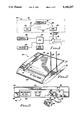
- FIG. 3 shows the rear of the FMD housing, and illustrates the preferred placement of the key switch, power cord, power cord strain relief fixture, and RJ-11 jacks;
- FIG. 4 shows an exploded view of the power cord strain relief fixture, including its attachment means, and the distal end of the power cord;
- FIG. 5 shows a portion of the rear of the FMD housing with the power cord strain relief fixture removed, revealing the infrared (IR) communications port that includes two holes, one for transmitting IR communication and the other for receiving IR communication signals;
- IR infrared
- FIG. 6 diagrammatically illustrates an IR coupling head that may be detachably secured to the rear of the FMD in place of the power cord strain relief fixture;
- FIG. 7 shows an infrared programming adapter that includes the IR coupling head of FIG. 6, and that is used to couple the IR communications port on the rear of the FMD to an external programming device;
- FIG. 8A diagrammatically shows the FMD coupled to an external through the IR adapter of FIG. 7, with the main elements of the external programming device being represented in block diagram form;
- FIG. 8B diagrammatically shows an external peripheral device coupled to the FMD through the IR communications port
- FIG. 9 is a schematic diagram of the IR communications port within the FMD.
- FIG. 10 is a schematic diagram of the IR adapter of FIG. 7,
- FIG. 11 is a block diagram of the FMD
- FIG. 12 is a simplified flow chart of the program used within the microprocessor of the FMD to restrict access to authorized personnel;
- FIGS. 13A, 13B, and 13C are a flow chart showing the method used by authorized personnel to gain high level access to the FMD.
- FIG. 1 a block diagram of an active electronic house arrest monitoring (EHAM) system 30.
- EHAM active electronic house arrest monitoring
- FMD field monitoring device
- the active EHAM system 30 includes a plurality of remote monitoring areas 32 and a central processing unit (CPU) 34.
- the CPU 34 is coupled to the remote monitoring area 32 by way of a residential telephone line 36.
- One or more conventional switching stations 38 couple the phone line 36 to the CPU 34.
- Such switching stations 38 are conventional switching stations commonly employed by the telephone company.
- other types of telecommunicative contact could also be used to connect the CPU 34 to the remote monitoring area 32.
- each remote area 32 there is included a field monitoring device (FMD) 40.
- the FMD 40 receives periodic signals 42 from an identification tag 44.
- These identification (ID) signals 42 contain information that uniquely identifies the tag 44 from which the signal originates.
- the ID signals 42 may also indicate, in some embodiments, the status of the circuits internal to the tag, and especially whether such circuits have sensed an attempt to remove or otherwise tamper with the tag.
- the system may also include a repeater 46 that can be selectively positioned within the area 32.
- the purpose of the repeater 46 is to receive the ID signals 42 from the tag 44 and retransmit these signals, after a short delay, to the FMD 40 to eliminate dead spots. Such retransmitted signals are identified in FIG. 1 as signals 42'.
- each tag 44 While only one tag 44 is shown in FIG. 1, it is understood that most EHAM systems can function with a plurality of tags 44 within the monitoring area 32, all of which are monitored by the same FMD 40. In such instance, each tag generates its own unique ID signal at periodic intervals.
- the CPU 34 is coupled through the telephone switching network 38, or through an equivalent telecommunicative link, to a large number of remote monitoring areas, each of which has its own FMD.
- the CPU 34 typically polls the FMDs at each of the remote monitoring areas, either randomly or in a prescribed sequence, in order to receive data that indicates the presence or absence of specific tags (and hence specific offenders to whom the specific tag has been assigned) at each of the remote locations.
- the FMD 40 is programmed to initiate a telephone call to the CPU 34, or to otherwise establish a telecommunicative link with the CPU 34, so that such tamper condition may be reported to the CPU as soon as possible.
- Coupled to the CPU 34 is at least one terminal 48 that provides a means for the CPU 34 to display the status of the various remote monitoring areas to which it is coupled, as well as to provide an operator the means for entering data or instructions into the CPU.
- Such terminals 48 are common in the art, typically including a CRT or LCD display screen and keyboard.
- a printer 50 that can be used to print status reports and other information concerning the operation of the EHAM system 30.
- the operation and construction of the elements of the EHAM system 30 shown in FIG. 1 may be as is known in the art.
- the present invention is directed to particular improvements that are included in the FMD 40, and more particularly to improvements that make the operation and use of the FMD 40 more secure, i.e., less susceptible to attempts to interfere with its operation through the unauthorized altering of the operating parameters stored within the FMD.
- FIG. 11 A representative block diagram of the FMD 40 is shown in FIG. 11. This block diagram is fully explained in U.S. Pat. No. 4,912,432, incorporated herein by reference, where the same figure appears as FIG. 12.
- the FMD 40 includes a microprocessor 130 to control the operation of the FMD.
- This microprocessor 130 is coupled to suitable memory circuits 134. These memory circuits include both random access memory (RAM) devices, electronically erasable programmable read only memory (EEPROM) devices, and erasable programmable read only memory devices (EPROM).
- RAM random access memory
- EEPROM electronically erasable programmable read only memory
- EPROM erasable programmable read only memory
- an operating program for the microprocessor 130 is stored in the EPROM, and is used to control the operation of the FMD.
- This operating program includes certain operating parameters, usually stored in EEPROM, but some of which may at least temporarily be stored in RAM, that define how the FMD operates. It is critically important to the integrity of the EHAM system that these operating parameters be protected, and not altered or changed, except by authorized personnel. Accordingly, one of the main purposes of the present invention is to protect these FMD operating parameters as stored in the memory circuits of the FMD so that only authorized personnel have access to evaluate (read) them, and/or to change (write) them as required in order to meet the needs of a particular EHAM application.
- the present invention includes a plurality of security features that restrict access to the circuits within the FMD.
- One of the security features used by the present invention is to enclose such circuits within a closed housing 52.
- FIG. 2 shows a generally frontal pictorial representation of the FMD 40, and illustrates the general appearance of its housing 52.
- the housing 52 provides an attractive, yet ruggedized, enclosure for the FMD circuits. It includes two spaced-apart antennas, 53 and 55, for receiving the ID signals 42 or 42' from the tags or repeaters. It also includes three status lights that are visible from the front of the device.
- red "phone busy” indicator light 57 (which is optionally lighted whenever the offender's phone line is busy), a yellow “unit home” light 59 (which is optionally lighted whenever the FMD receives an ID signal), and a green "power” light 61 (which is lighted whenever power is applied to the FMD and the FMD is operating in its normal monitoring mode).
- these indicator lights are located in a recess channel 58 that parallels one edge of the housing 52.
- a name plate 60, or equivalent area or design, e.g., showing the manufacturer's name and model number of the FMD, may also be optionally included on the front of the
- the housing 52 essentially comprises two halves, an upper half 54 and a lower half 56.
- the two halves 54 and 56 are not joined together, and the electronic circuits and other components of the FMD, as shown in the block diagram of FIG. 12, are fully accessible for purposes of assembly and test.
- the two halves Once the two halves are joined together, as a final step of the assembly of the FMD, they cannot be taken apart without destroying at least a portion of the housing 52. Hence, some measure of physical security for the FMD circuits is provided through the use of the closed housing 52.
- a telecommunicative link e.g., a telephone line and/or telephone
- the physical means for providing the desired electrical or signal access into the FMD circuits after the FMD housing 52 is closed is provided by way of two data communication ports and a power input jack, located on the rear of the lower half 56 of the housing 52, as shown in FIG. 3.
- a first data communication port 62 allows a conventional RJ-11 telephone jack to be plugged into one of two RJ-11 connectors.
- Two RJ-11 connectors are provided so that the FMD can be connected to both the standard telephone wall jack and to a standard telephone.
- An appropriate phone line tamper detect circuit 150 (FIG. 11) is coupled to the connectors 62 to detect any disconnection or tampering with these connectors. Such circuit also provides electrical isolation between these jacks and the other circuits within the FMD.
- the other data communication port provided on the FMD housing 52 is not visible in FIG. 3. This is by design. Rather, it is concealed behind a strain relief fixture 64 that is detachably secured to the rear of the housing 52 by means of an attachment screw 65.
- the attachment screw 65 in one embodiment, includes a special nonstandard head design that requires the use of a special tool 67 in order to remove it. Thus, only those having the special tool 67 are able to easily remove the screw 65, or equivalent attachment means.
- the attachment screw 65 fits through a hole 63 in the strain relief fixture 64.
- a power cord 66 is secured to the FMD 40 by means of the strain relief fixture 64.
- a conventional AC adapter 68 designed for direct, insert,ion into a standard AC wall outlet, generates and appropriate AC voltage that is provided by way of the power cord 66 to the circuits internal to the FMD.
- a distal end of the power cord 66 includes a conventional DC plug tip that extends from an insulated hand grip 71.
- a smaller insulated support 76 extends rearwardly from the grip 71.
- a rear shoulder 72 defines the change from the grip 71 to the support 76. This shoulder 72 is adapted to engage the edge of a ring 73 that forms an integral part of the strain gauge relief fixture 64.
- a hole 75 through the center of the ring 73 is sized to be just slightly larger in diameter than the support 76 of the power cord 66.
- the ring 73 further includes a slot 74 through which the power cord 66 may readily fit.
- the support 76 may be slid into the center 75 of the ring 73 until the shoulder 72 engages the edge of the ring 73.
- the connector tip 70 is then inserted into the power jack on the rear of the FMD, and the entire strain relief fixture 64 is then secured to the rear of the FMD, thereby firmly seating the power cord connector 70 in its respective jack on the rear of the FMD housing.
- a key switch 78 is also included on the rear of the FMD housing 52.
- This key switch 78 may be of conventional design, and includes two positions, labeled OFF and ON. The key switch 78 can be moved from one position to the other only by inserting a key into the switch and turning the key. Only key switch 78. Thus, only authorized personnel are able to turn the key switch ON or OFF.
- a manufacturer's label 80 identifying the serial number and other identifying data with the FMD 40, is typically included on the rear of the FMD housing, as shown in FIG. 3.
- FIG. 5 there is shown a portion of the rear of the FMD housing 52 with the power cord strain relief fixture 64 removed. With the strain relief fixture removed, and with the power cord 66 unplugged (as shown in FIG. 5), a power jack 82 is readily visible. The connector tip 70 of the power cord 66 mates with the jack 82. Also visible is a threaded screw hole 84 for receiving the attachment screw 65. In addition, two small holes 86 and 88 are seen. These two holes 86 and 88, and the circuitry behind them (discussed below in connection with FIG. 9), comprise the other data communications port referred to above. This other data communications port is an infrared (IR) communications port 90.
- IR infrared
- Such IR communications port 90 advantageously physically and electrically isolates the circuits within the FMD from anything external to the FMD. Yet, data signals can still be readily sent and received. Hence, the use of a metallic or other electrically conductive connector, through which an offender might introduce a static or other charge into the circuits of the FMD, is avoided.
- Data signals are received through one of the holes, e.g., the hole 86, by way of a modulated infrared beam of light that is directed to the hole from a source external to the hole.
- data signals are sent through the other hole, e.g, the hole 88, by sending a modulated IR beam to an IR receiving source external to and aligned with such hole.
- an IR adapter 92 is used. Such an IR adapter 92 is shown in FIGS. 6 and 7.
- the IR adapter 92 includes a coupling head 95, an interface box 98, a power supply 68', and a connector 102.
- the coupling head 95 is connected to the interface box 98 by way of a conventional electrical cable 96.
- the connector 102 is coupled to the interface box 98 by way of an appropriate electrical cable 100.
- the power supply 68' which may be a conventional AC converter, the same as is used to power the FMD directly, connects to the interface box by way of a power cord 66'.
- Power from the AC adapter 68' is used to power the circuits in the interface box 98, as well as to power the FMD, as controlled by an on/off switch 97. That is, a portion of the cable 96 includes DC power, controlled by switch 97, that is broken out of the cable 96 at the coupler head 95 and connected to an appropriate power connector 70'.
- the power connector 70' may be the same as previously described relative to the power connector 70.
- the coupling head 95 includes a support plate 94 that is approximately the same size as the strain relief fixture 64.
- Such support plate 94 includes a hole 93 through which the attachment screw 65 may be inserted in order to secure the coupling head to the rear of the FMD.
- the support plate also includes a ring 73' for seating and securing a power cord to the FMD, the same as has been previously described.
- the coupling head includes an appropriate IR emitter and detector. Such IR emitter and detector are spatially positioned on the support plate 94 so as to be in alignment with the holes 86 and 88 of the IR communications port 90 when the coupling head is detachably secured to the FMD in place of the strain relief fixture 64.
- the FMD 40 is shown coupled to an external programming device ("programmer") 104 through the IR adapter 92.
- the programmer 104 may be realized using any suitable device having means for generating the appropriate data signals, such as a personal computer (PC) or equivalent work station.
- the programmer 104 includes a keyboard 106, a display 108, and if desired, a printer 110.
- the operation of the programmer is conventional. That is, data is coupled to and from the programmer 104 through either a serial or parallel port to which the connector 102 of the IR adapter 92 is connected.
- the IR adapter 92 may couple to a modem, and the programmer 104 may then access the IR adapter and FMD through any standard telecommunicative link accessible through the modem.
- the programmer it is possible for the programmer to be physically located some distance from the FMD, if needed.
- FIG. 8B diagrammatically shows an external peripheral device 112 coupled to the FMD 40 through the IR communications port.
- a connecting cable 114 between the peripheral device 112 and the FMD 140 may be realized using fiber optics, thereby avoiding the need for the IR adapter 92.
- the peripheral device 112 may be coupled to the FMD 40 through the IR adapter 92, or equivalent.
- the peripheral device 112 may be any desired device that supplements the monitoring operation of the FMD.
- the device 112 may include means for analyzing the breath of the offender to determine if the offender has been drinking alcohol.
- the device 112 may measure any desired physiological parameter of the offender, such as heart rate, etc., in an attempt to ascertain whether the offender is under the influence of drugs.
- the device 112 may include circuits for analyzing the speech of the offender, either for the purpose of identifying the offender or to determine if the offender is under the influence of alcohol or drugs (resulting in slurred speech).
- the device 112 could include means for electronically analyzing the handwriting of the offender, again either for the purpose of identifying the offender or to determine if the offender is under the influence of some type of drug.
- the device 112 may also include circuitry for electronically sensing the fingerprint of the offender. Any or all of the above types of supplemental monitoring, or similar types of monitoring, may be carried out by the peripheral device 112, which device 112 may be coupled to the FMD through the IR communications port 90.
- FIG. 9 a schematic diagram of the IR communications port 90 used within the FMD 40 is shown.
- the holes 86 and 88 included in the rear of the FMD housing are symbolically depicted in FIG. 9 as cylinders. Infrared light passing through the hole 86 strikes the base of IR sensitive transistor Q1, causing Q1 to conduct. With Q1 conducting, a current flows through resistor R1, connected between the emitter of Q1 and ground, causing the voltage at the emitter of Q1 to rise. This voltage passes through buffer invertor gate U2, and is routed through one of the poles of a multiple-pole solid state switch U1 to a receive terminal line, RXD. The RXD terminal line may then be coupled to the microprocessor 130 within the FMD.
- Pulsed infrared light that impinges upon the base of Q1 in accordance with an appropriate data modulation pattern thus causes corresponding electrical pulses to appear at the emitter of transistor Q1, which electrical pulses are then transferred to the microprocessor through one of the poles of the switch U1.
- pulses of infrared light representing desired data that is to be transmitted through the hole 88, are generated by light emitting diode DS1 whenever transistor Q2 is turned on.
- the diode DS1 is positioned in alignment with the hole 88. Infrared light is generated by the diode whenever current flows therethrough.
- the anode of the diode is connected to the emitter of PNP transistor Q2, which may be, e.g, a 2N3906 transistor.
- Transistor Q2 is turned on by applying a low voltage to its base, and is turned off by applying a high voltage to its base.
- data to be transmitted is presented to the base of Q2 in an appropriate modulation pattern through resistor R2. This data may be obtained from the transmit terminal line, TXD, obtained from the microprocessor 130 of the FMD through another of the poles of the switch U1.
- the emitter diode DS1 may be realized using an SFH409 diode, or equivalent diode, available from numerous semiconductor vendors Siemens.
- the infrared detector Q1 may be realized using an SFH309 transistor, or equivalent transistor, also available from the same semiconductor vendors.
- the multi-pole switch U1 may be realized using a commercially available 4066 quad switch, also available from various semiconductor vendors.
- the infrared communications port 90 further includes means for directing test data available at a test terminal MODRXD directly to the microprocessor 130 (which microprocessor may be a 63A03A processor manufactured by Hitachi) through the receive data terminal RXD in lieu of the data received through the IR detector Q1.
- test data from the microprocessor may be directed to a test terminal MODTXD rather than to the IR emitter DSI. This option is made available through the use of other poles of the multi-pole switch U1.
- a control signal, CMODE controls the operation of the multi-pole switch U1 in conventional manner in order to connect the desired RXD signal source, i.e., the IR detector Q1 or test data, to the microprocessor RXD terminal.
- the control signal, CMODE also controls switch U1 to connect the desired TXD signal source originating at the microprocessor to either the IR emitter DSI or the test terminal MODTXD.
- Manufacturing jumpers typically coupled to the microprocessor, are strategically placed within the FMD circuits, advantageously allowing access to the desired FMD circuits without having to successfully pass the stringent and time consuming access procedures described below in connection with FIGS. 12 and 13. That is, with the manufacturing configuration jumpers in place, the FMD bypasses the security measures described elsewhere herein.
- the infrared link 90 may be used to communicate with the FMD for the purposes of invoking various manufacturing diagnostic tests and annunciating test results.
- the manufacturing jumpers are removed. Once removed, all of the security measures must thereafter be followed in order to transmit data through the IR link 90.
- the use of such manufacturing jumpers thus facilitates the expeditious manufacture of the FMD in that the time consuming authorization validation techniques are avoided that would normally have to be followed in order to transfer data through the IR communications port.
- FIG. 10 shows a schematic diagram of the IR adapter 92 shown pictorially in FIG. 7.
- the coupling head 95 of the adapter includes an IR detector Q3 and an IR emitter DS2.
- the IR detector Q3 may be realized using an SFH309 transistor, the same as was used for the IR detector Q1 in the FMD.
- the IR emitter DS2 may be realized using an SFH409 diode, the same as was used for the IR emitter DS1 in the FMD.
- the IR detector Q3 is aligned within the coupling head 95 so as to receive any IR signals emitted from the hole 88 by the IR emitter DS1 in the FMD.
- the IR emitter DS2 is aligned within the coupling head 95 so as to transmit any IR signals through the hole 86 to the IR detector Q1 in the FMD. Emitter DS2 is controlled by switching transistor Q4 within the interface box 98.
- An interface circuit 122 such as the MAX 232 TTL converter available from MAXIM, couples and buffers the signals from the IR detector Q3 and the signals used to control the switching transistor Q4 (which in turn controls the emitter DS2) as such signals pass through the cable 100 as they are sent to or received from the programmer 104.
- Indicator lights driven by appropriate indicator driver circuit 120, light up whenever the appropriate data is present. Thus, when data is being transmitted, a yellow indicator light, labeled TXD, is lighted. When data is being received, a red indicator light, labeled RXD, is lighted.
- switch 97 that controls the delivery of power to the FMD through the power connection jack 70'.
- the use of such switch facilitates access into the FMD circuits as part of the access procedure explained more fully below, which access procedure requires that power be applied to the FMD in a specificed sequence relative to other events that must also occur.
- FIG. 11 is a representative block diagram of the FMD 40. This block diagram, and the basic operation of the FMD, have been described elsewhere. Equivalent FMD configurations may, of course, be used. For purposes of the present invention, any FMD configuration that uses a microprocessor, or equivalent circuit, controlled by operating parameters stored in a memory device, may utilize the present invention.
- the FMD circuits are housed in a closed housing that cannot be opened.
- the communications port through which data access to the FMD memory circuits is obtained is physically hidden on the FMD housing.
- the hidden communications port can only be made visible through the use of a special tool.
- the communications port is visible, it does not necessarily appear as a communications port. No conventional connectors are used. Rather, because the port utilizes IR signals, which signals pass through air, the port simply comprises two small, spaced-apart holes. Without knowledge of the IR communications port and its function, the presence of the IR communications port may thus not even be recognized.
- an important feature of the present invention is to provide additional restrictions that control access to the operational parameters stored in the FMD. Such additional restrictions are imposed by the main operating program of the microprocessor, coupled with appropriate logic circuitry.
- FIG. 12 A simplified flow chart of the main steps imposed by the FMD in order to further restrict and control access to its operational parameters is shown in the flow chart of FIG. 12.
- FIG. 12 as well as the other flow charts described herein, each main step of the described process is shown as a "box” or “block”, with each box or block having a corresponding reference number.
- a first step in limiting access to the operational parameters of the FMD is to make a determination as to whether the key switch is in the "proper" or specified position (block 160). Additionally, in some embodiments, a determination may also be made at this time as to whether a programmer, or equivalent device, is coupled to the IR communications port (block 160). If this determination is made, some type of coordination or "handshaking" is required between the programmer or other device, e.g., so that if a certain bit sequence is transmitted by the FMD, a corresponding bit sequence is retransmitted back to the FMD.
- the FMd simply performs its normal operating functions as if nothing unusual had happened (block 170).
- the FMD issues a series of six short beeps (block 174). There is a few seconds delay between each beep. Some of the indicator lights on the front of the FMD may also come on and go off in synchrony with these beeps. For example, at the first beep, the green "power" light 61 (FIG. 2) may come one. At the second beep, the yellow "unit home” light 59 may come on, making a total of two lights that are on.
- the red "phone busy” light 57 may come one, making a total of three lights that are on.
- the green "power" light 61 may go off, leaving the yellow light 59 and the red light 57 on.
- the yellow light 59 may go off, leaving only the red light 57 on.
- the red light 57 may go off, thereby leaving all of the lights off.
- the access method used by the present invention provides different levels of security access to the operating parameters as a function of the operating personnel's security access level. Those having a low security level access (not needing access to all of the operating parameters) are not given the same passwords and operational knowledge concerning accessing the FMD as are those who have a high security access level (needing access to all of the operating parameters). Those who have a high security access level know that after each beep, a prescribed action must be quickly taken prior to the occurrence of the next beep. In general, this prescribed action involves keying in a specified access code at the same time that a designated key is held in the depressed position.
- a high security flag is set (block 180). If not, then the high security flag is reset (block 180). Those having a low security level access have no knowledge concerning the entry of the access codes after each beep, and hence do not even attempt such entry. Thus, for such low security level access personnel, the high security flag is always reset.
- the FMD next generates a long beep (block 182).
- a time window or time interval begins (block 184) during which the person attempting access must enter a valid password.
- a password comprises a particular sequence of alphanumeric characters, such as "ABCDEFGHI". Typically, this time window is on the order of 5-10 seconds, preferrably 5 seconds. If a valid password is not entered during the time window (block 186), then nothing happens, unless the keyswitch is switched from its proper position (block 187), and the access sequence must be initiated again (i.e., power must be removed from the FMD, the key switch must be turned to its proper position, power reapplied, etc.).
- the FMD performs its normal monitoring function. If however, a valid password is entered during the time window (block 184), then a determination is next made as to whether the high security flag is set (block 190). If so, a high security access mode is enabled where full access is granted to the entire set of operating parameters (block 192). If not, a low security access mode is enabled where only partial access is granted to some of the operating parameters (block 190).
- Table 1 below lists various operating parameters that are typically programmed into an FMD and the level of security that allows access to each one. As seen in Table 1, a high security access level allows all of the operating parameters to be accessed and modified. A low security access level, on the other hand, allows only a subset of the operating parameters to be accessed. Low level security access is usually granted to those who install the FMD, and monitor its use while in the field. High level security access, on the other hand, is granted only to those who need such access, as manufacturing engineers, troubleshooters, or others who have to keep the EHAM system operational.
- the method used by authorized personnel to gain high level access security to the FMD will next be described. This is the same method used during the manufacture of the FMD in order to customize the FMD for a particular monitoring application.
- the FMD case is closed.
- the external programmer can send and receive data through an appropriate communications port in full duplex, 8 bit, no parity, at 1200 baud.
- two RS232 ports are available on the programmer, and that the programmer is set to an Upper Case mode.
- a serial printer is connected to one of the RS232 ports.
- the IR adapter is connected to the other RS232 port.
- a representative terminal that could be used as the programmer is a WYSE 30, available from WYSE Technology.
- a phone line simulator and recorder are connected to the RJ-11 connectors on the rear of the FMD (block 202, FIG. 13A).
- the key switch is then turned to the "proper" position (block 204).
- the FMD is interfaced with the IR adapter through the IR communications port on the rear of the FMD as previously described.
- One of the RS232 ports of the external programmer is then connected to the other side of the IR adapter, thereby coupling the external programmer to the FMD through its IR communications port (block 206).
- Power is next applied to all of the devices except the FMD (block 208). Then, power is applied to the FMD (block 210).
- a long beep After entering the appropriate access codes after each of the six beeps, a long beep will sound (block 224). At the conclusion of the long beep, the [CTRL] key may be released (block 226). Further, at the end of the long beep, a five-second window exists during which a second password, of the form "ZYXWVUTSR", must be entered (block 228). If the second password is not entered correctly within the five second time window, AC power must be removed and the cycle started over.
- the data stored in the EEPROM of the FMD is displayed on the terminal screen of the programmer (block 230) as a first screen, SCREEN1.
- a representation the type of information included in the SCREEN1 display is shown below in Table 2.
- the operator can select whether or not this information should be erased (block 232). Typically, it is not necessary to erase the EEPROM, so depressing the [RETURN] key enters the default NO. If the erase option is selected, then the EEPROM is erased (block 234).
- SCREEN1 After SCREEN1 is viewed, and a decision is made as to whether the EEPROM data is to be erased, a second screen of information, SCREEN2, is displayed (block 236, FIG. 13B). A representation of the type of information included in the SCREEN2 display is shown in Table 3.
- the SCREEN2 information displays the information currently programmed in the EEPROM in a more easily understand format (not hexadecimal). After displaying SCREEN2, the operator can select whether or not this information is to be configured (block 238), i.e., reprogrammed, by entering "Y", [RETURN]. If the operator selects the CONFIGURE option, another screen, SCREEN3, is displayed (block 240). SCREEN3 repeats the same information contained in SCREEN2, but with the current EEPROM data in brackets. The information in brackets thus represents default data, and depressing the [RETURN] key does not change the data. If it is desired to change the data, the new data is entered and the [RETURN] key is depressed (block 242). In this way, some or all of the information shown in SCREEN3 may be modified.
- SCREEN4 (block 244).
- Table 4 shows a representation of the information contained in SCREEN3 when it is first displayed
- Table 5 shows a representation of SCREEN4, i.e., the information of SCREEN3 after it has been selectively modified.
- SCREEN4 After displaying SCREEN4, the operator is asked whether there are any more changes (block 246). If so, such changes are made as described above (blocks 242, If no additional changes are made, the operator is asked whether the changes shown on SCREEN4 are to be programmed into the EEPROM (block 248). If the operator indicates yes ("Y"), the changes are made in (written to) the EEPROM (block 250). If the operator indicates no ("N"), then the changes shown on the screen, SCREEN4, are not made in the EEPROM. In either event, after this selection and resulting action (blocks 248, 250), SCREEN1 is again displayed (block 252), a representation of which screen was shown above in Table 1. Basically, this display is the hexadecimal data as stored in the EEPROM at that time (after the modifications).
- a "HELLO" message appears (block 254).
- the operator should then activate the matching transmitter tag 44 (FIG. 1) associated with the FMD two times, about five seconds apart (block 256). Each activation should produce either a tampered or untampered beep, depending on the status of the transmitter at the time it is activated. If a correct response is received (block 258), then the FMD dials its internally programmed telephone number (block 262) after about a 30 second delay (block 260). This number is printed out on the Phone Line Recorder. The operator checks this number to make sure it matches the desired number (blocks 264, 266). If it does, the operator may print the last displayed screen to the printer, if desired (block 268).
- the present invention thus provides an FMD for use in an EHAM system that is "secure", i.e., an FMD that is substantially tamper proof, and that is immune to attempts to thwart its proper operation.
- the FMD provided by the invention utilizes a more secure method of accessing and programming the FMD. This is accomplished through the use of a nonstandard communication link between the FMD and an external programmer.
- this link does not have any exposed connectors or other visible communication ports through which an offender might be tempted to interfere or tamper with the operation of the FMD.
- the secure FMD provided by the invention includes different levels of access to the FMD's operational parameters.
- Programmable access to a full set of the programmable FMD operational parameters is granted only to those having a full knowledge of all of the prescribed conditions and multiple passwords, and the timing associated with when such passwords must be entered.
- Programmable access to a subset of the full set of operational parameters is granted to those having some knowledge, but not a complete knowledge, about the prescribed conditions and password, such as a field representative or installer. In this manner, the operational parameters are safeguarded by restricting their availability on a "need to know" or "need to access" basis.
- an FMD made in accordance with the present invention does not exhibit any behavior other than what would be considered normal operation when there is a failed attempt to gain access.
- unauthorized individuals who have no knowledge of the access mechanisms are not "clued in” to the fact that any such access means exists.
- the present invention advantageously provides a secure FMD for use with an EHAM system wherein the factory testing and programming of the FMD is not encumbered or slowed down by the time-consuming access restrictions that are used to safeguard the operating parameters programmed within the FMD.
- the FMD of the present invention also provides a secure nonstandard communication interface with optional peripheral detecting and monitoring devices, external to the FMD, that may be desirable to use for some EHAM applications.
- optional peripheral devices may include, for example, voice verification circuits, alcohol detection devices, signature analysis apparatus, and the like.
Abstract
Description
              TABLE 1
______________________________________
FMD Operating Parameters and Access Levels
                   High     Low
Parameter          Security Security
______________________________________
Unit Number        X
Transmitter code   X
Date of Manufacture
                   X
Serial Number      X
Phone Number       X        X
Tone or Pulse Dial X        X
Unit Home LED Enable
                   X        X
Hours to first test report
                   X        X
Hours between test reports
                   X        X
Customer Programmable
                   X
Customer Password  X        X
Manufacturer Password
                   X
Transmitter Range  X        X
Leave Window       X        X
______________________________________
                                  TABLE 2
__________________________________________________________________________
BI P/N: 9-70-13007-00 Rev. A
Firmware ID: BIC4000AM, Version 1.00.03, Jun 26 1990, 13:42:01
Copyright (C) 1990 by BI Incorporated. All Rights reserved.
__________________________________________________________________________
0000:
   0000
       10E1
           9914
               2F5B
                   B186
                       0008
                           0004
                               0801
                                   . . . /C . . .
0008:
   0C40
       8731
           AD98
               312C
                   3535
                       3535
                           3535
                               3500
                                   .@.1..1.5555555.
0010:
   0000
       0000
           0000
               0000
                   0000
                       FFFF
                           FFFF
                               FFFF
                                   . . .
0018:
   FFFF
       FFFF
           FFFF
               FFFF
                   FFFF
                       FFFF
                           FFFF
                               FFFF
                                   . . .
0020:
   FFFF
       FFFF
           FFFF
               FFFF
                   FFFF
                       FFFF
                           FFFF
                               FFFF
                                   . . .
0028:
   FFFF
       FFFF
           FFFF
               FFFF
                   FFFF
                       FFFF
                           FFFF
                               FFFF
                                   . . .
0030:
   FFFF
       FFFF
           FFFF
               FFFF
                   FFFF
                       FFFF
                           FFFF
                               FFFF
                                   . . .
0038:
   FFFF
       FFFF
           FFFF
               FFFF
                   FFFF
                       FFFF
                           FFFF
                               2DE1
                                   . . .
Erase? [No]
__________________________________________________________________________
              TABLE 3
______________________________________
UNIT NUMBER:            4321
XMTR CODE:              8 (08 hex)
PHONE NUMBER:           1,5555555
HOME LED ENABLE:        No
HRS TO 1ST AUTO TEST REPORT:
                        4
HRS BETWEEN AUTO TEST REPORTS:
                        8
CUSTOMER PROGRAMMABLE   Yes
CUSTOMER PASSWORD:      ABCDEFGHI
BI PASSWORD:            ZYXWVUTSR
Any Changes?
______________________________________
              TABLE 4
______________________________________
UNIT NUMBER:            [4321] 1234
XMTR CODE:              [8] 6
PHONE NUMBER:           [1,5555555] 1,8005555555
HOME LED ENABLE:        [No]
HRS TO 1ST AUTO TEST REPORT:
                        [4]
HRS BETWEEN AUTO TEST REPORTS
                        [8]
CUSTOMER PROGRMMABLE:   [Yes]
CUSTOMER PASSWORD:      ABCDEFGHI
BI PASSWORD:            ZYXWVUTSR
Any Changes?
______________________________________
              TABLE 5
______________________________________
UNIT NUMBER:            1234
XMTR CODE:              6 (06 hex)
PHONE NUMBER:           1,8005555555
HOME LED ENABLE:        No
HRS TO 1ST AUTO TEST REPORT:
                        4
HRS BETWEEN AUTO TEST REPORTS:
                        8
CUSTOMER PROGRAMMABLE:  Yes
CUSTOMER PASSWORD:      ABCDEFGHI
BI PASSWORD:            ZYXWVUTSR
Any Changes?
______________________________________
Claims (20)
Priority Applications (1)
| Application Number | Priority Date | Filing Date | Title |
|---|---|---|---|
| US07/723,481 US5146207A (en) | 1991-07-01 | 1991-07-01 | Secure field monitoring device for use in electronic house arrest monitoring system |
Applications Claiming Priority (1)
| Application Number | Priority Date | Filing Date | Title |
|---|---|---|---|
| US07/723,481 US5146207A (en) | 1991-07-01 | 1991-07-01 | Secure field monitoring device for use in electronic house arrest monitoring system |
Publications (1)
| Publication Number | Publication Date |
|---|---|
| US5146207A true US5146207A (en) | 1992-09-08 |
Family
ID=24906454
Family Applications (1)
| Application Number | Title | Priority Date | Filing Date |
|---|---|---|---|
| US07/723,481 Expired - Fee Related US5146207A (en) | 1991-07-01 | 1991-07-01 | Secure field monitoring device for use in electronic house arrest monitoring system |
Country Status (1)
| Country | Link |
|---|---|
| US (1) | US5146207A (en) |
Cited By (38)
| Publication number | Priority date | Publication date | Assignee | Title |
|---|---|---|---|---|
| US5255306A (en) * | 1991-01-10 | 1993-10-19 | Bi Inc. | Cellular interface unit for use with an electronic house arrest monitoring system |
| US5438607A (en) * | 1992-11-25 | 1995-08-01 | U.S. Monitors, Ltd. | Programmable monitoring system and method |
| US5461390A (en) * | 1994-05-27 | 1995-10-24 | At&T Ipm Corp. | Locator device useful for house arrest and stalker detection |
| US5576689A (en) * | 1993-08-27 | 1996-11-19 | Queen; Andrew | Self testing personal response system with programmable timer values |
| US5742238A (en) * | 1995-09-01 | 1998-04-21 | Emtrak, Inc. | System for communication between a central controller and items in a factory using infrared light |
| US5912623A (en) * | 1997-11-28 | 1999-06-15 | Alert Systems Corporation | House arrest monitoring system with improved tamper detection |
| EP0902401A3 (en) * | 1997-07-24 | 1999-12-29 | Elmo-Tech Ltd | Electronic monitoring system |
| US6054928A (en) * | 1998-06-04 | 2000-04-25 | Lemelson Jerome H. | Prisoner tracking and warning system and corresponding methods |
| US6138058A (en) * | 1998-01-06 | 2000-10-24 | Jenoptik Infab, Inc. | Method for electronically tracking containers to avoid misprocessing of contents |
| US6148219A (en) * | 1997-02-18 | 2000-11-14 | Itt Manufacturing Enterprises, Inc. | Positioning system for CDMA/PCS communications system |
| US6148195A (en) * | 1997-02-18 | 2000-11-14 | Itt Manufacturing Enterprises, Inc. | Phase agile antenna for use in position determination |
| US6181253B1 (en) | 1993-12-21 | 2001-01-30 | Trimble Navigation Limited | Flexible monitoring of location and motion |
| US6489893B1 (en) | 1998-03-23 | 2002-12-03 | Time Domain Corporation | System and method for tracking and monitoring prisoners using impulse radio technology |
| US6492906B1 (en) | 1998-03-23 | 2002-12-10 | Time Domain Corporation | System and method using impulse radio technology to track and monitor people under house arrest |
| US6674368B2 (en) | 2000-08-28 | 2004-01-06 | Continental Divide Robotics, Inc. | Automated tracking system |
| US6693543B1 (en) | 1999-05-05 | 2004-02-17 | Guidance Control Systems Limited | Tagging device |
| US6844816B1 (en) | 1999-10-05 | 2005-01-18 | Bi Incorporated | Authentication techniques in a monitoring system |
| US20050210268A1 (en) * | 1999-07-01 | 2005-09-22 | T-Netix, Inc. | Off-site detention monitoring system |
| US20060244613A1 (en) * | 2005-04-29 | 2006-11-02 | Myers Steven B | Remote Controlled: locking wrist and/or ankle incapacitating electroschock stun bracelet for prisoner control |
| US20080122613A1 (en) * | 2006-11-29 | 2008-05-29 | Joan Sanger | System and Method for Reducing Recidivism and Aid in Transition From a Structured Living Situation to a Less Structured Situation |
| US20100123589A1 (en) * | 2008-11-14 | 2010-05-20 | Bi Incorporated | Systems and Methods for Adaptive Monitoring of Physical Movement |
| US7737841B2 (en) | 2006-07-14 | 2010-06-15 | Remotemdx | Alarm and alarm management system for remote tracking devices |
| US7804412B2 (en) | 2005-08-10 | 2010-09-28 | Securealert, Inc. | Remote tracking and communication device |
| US7936262B2 (en) | 2006-07-14 | 2011-05-03 | Securealert, Inc. | Remote tracking system with a dedicated monitoring center |
| US20110133937A1 (en) * | 2009-12-03 | 2011-06-09 | Bi Incorporated | Systems and Methods for Disrupting Criminal Activity |
| US20110133928A1 (en) * | 2009-12-03 | 2011-06-09 | Bi Incorporated | Systems and Methods for Variable Collision Avoidance |
| US20110154887A1 (en) * | 2007-03-06 | 2011-06-30 | Bi Incorporated | Transdermal Portable Alcohol Monitor and Methods for Using Such |
| US8232876B2 (en) | 2008-03-07 | 2012-07-31 | Securealert, Inc. | System and method for monitoring individuals using a beacon and intelligent remote tracking device |
| US8514070B2 (en) | 2010-04-07 | 2013-08-20 | Securealert, Inc. | Tracking device incorporating enhanced security mounting strap |
| US8657744B2 (en) | 2009-03-23 | 2014-02-25 | Bi Incorporated | Systems and methods for transdermal secretion detection |
| US8797210B2 (en) | 2006-07-14 | 2014-08-05 | Securealert, Inc. | Remote tracking device and a system and method for two-way voice communication between the device and a monitoring center |
| US8862152B1 (en) | 2012-11-02 | 2014-10-14 | Alcohol Monitoring Systems, Inc. | Two-piece system and method for electronic management of offenders based on real-time risk profiles |
| GB2516517A (en) * | 2013-01-22 | 2015-01-28 | Buddi Ltd | Blind spot determination |
| US9241661B2 (en) | 2012-09-17 | 2016-01-26 | TraceX, Inc. | Apparatus and method for extra-corporal chemical detection and monitoring |
| US9355548B2 (en) | 2009-12-03 | 2016-05-31 | Bi Incorporated | Systems and methods for contact avoidance |
| US11538324B2 (en) | 2020-08-26 | 2022-12-27 | Ping Geo Inc. | System and method for tracking and monitoring persons subject to restricted movements |
| US11665507B2 (en) | 2020-09-15 | 2023-05-30 | Bi Incorporated | Systems and methods for intercept directing in a monitoring system |
| US11701007B2 (en) | 2020-08-28 | 2023-07-18 | Bi Incorporated | Systems and methods for biometric tamper detection |
Citations (10)
| Publication number | Priority date | Publication date | Assignee | Title |
|---|---|---|---|---|
| US4528623A (en) * | 1980-12-05 | 1985-07-09 | Hitachi, Ltd. | Controller with programmer for selectively providing programs to operate controller |
| US4542452A (en) * | 1980-06-25 | 1985-09-17 | Yokogawa Hokushin Electric Corporation | Programmable controller |
| US4600918A (en) * | 1981-06-29 | 1986-07-15 | Indesit Industria Elettrodomestici Italiana Spa | Equipment for reproduction of alphanumerical data |
| US4691340A (en) * | 1984-11-28 | 1987-09-01 | Sony Corporation | Image information accessing user terminal |
| US4747120A (en) * | 1985-08-13 | 1988-05-24 | Digital Products Corporation | Automatic personnel monitoring system |
| US4777477A (en) * | 1987-04-27 | 1988-10-11 | Watson Ronald R | Surveillance alarm-security system |
| US4831226A (en) * | 1988-02-08 | 1989-05-16 | Amana Refrigeration, Inc. | Control system with hidden reprogramming switch |
| US4918432A (en) * | 1988-09-27 | 1990-04-17 | B. I. Incorporated | House arrest monitoring system |
| US4952928A (en) * | 1988-08-29 | 1990-08-28 | B. I. Incorporated | Adaptable electronic monitoring and identification system |
| US4965557A (en) * | 1982-07-29 | 1990-10-23 | Nokia Unterhaltungselektronik | Interactive control of entertainment electronics apparatus |
-
1991
- 1991-07-01 US US07/723,481 patent/US5146207A/en not_active Expired - Fee Related
Patent Citations (10)
| Publication number | Priority date | Publication date | Assignee | Title |
|---|---|---|---|---|
| US4542452A (en) * | 1980-06-25 | 1985-09-17 | Yokogawa Hokushin Electric Corporation | Programmable controller |
| US4528623A (en) * | 1980-12-05 | 1985-07-09 | Hitachi, Ltd. | Controller with programmer for selectively providing programs to operate controller |
| US4600918A (en) * | 1981-06-29 | 1986-07-15 | Indesit Industria Elettrodomestici Italiana Spa | Equipment for reproduction of alphanumerical data |
| US4965557A (en) * | 1982-07-29 | 1990-10-23 | Nokia Unterhaltungselektronik | Interactive control of entertainment electronics apparatus |
| US4691340A (en) * | 1984-11-28 | 1987-09-01 | Sony Corporation | Image information accessing user terminal |
| US4747120A (en) * | 1985-08-13 | 1988-05-24 | Digital Products Corporation | Automatic personnel monitoring system |
| US4777477A (en) * | 1987-04-27 | 1988-10-11 | Watson Ronald R | Surveillance alarm-security system |
| US4831226A (en) * | 1988-02-08 | 1989-05-16 | Amana Refrigeration, Inc. | Control system with hidden reprogramming switch |
| US4952928A (en) * | 1988-08-29 | 1990-08-28 | B. I. Incorporated | Adaptable electronic monitoring and identification system |
| US4918432A (en) * | 1988-09-27 | 1990-04-17 | B. I. Incorporated | House arrest monitoring system |
Cited By (49)
| Publication number | Priority date | Publication date | Assignee | Title |
|---|---|---|---|---|
| US5255306A (en) * | 1991-01-10 | 1993-10-19 | Bi Inc. | Cellular interface unit for use with an electronic house arrest monitoring system |
| US5438607A (en) * | 1992-11-25 | 1995-08-01 | U.S. Monitors, Ltd. | Programmable monitoring system and method |
| US5576689A (en) * | 1993-08-27 | 1996-11-19 | Queen; Andrew | Self testing personal response system with programmable timer values |
| US6181253B1 (en) | 1993-12-21 | 2001-01-30 | Trimble Navigation Limited | Flexible monitoring of location and motion |
| US5461390A (en) * | 1994-05-27 | 1995-10-24 | At&T Ipm Corp. | Locator device useful for house arrest and stalker detection |
| US5742238A (en) * | 1995-09-01 | 1998-04-21 | Emtrak, Inc. | System for communication between a central controller and items in a factory using infrared light |
| US6148219A (en) * | 1997-02-18 | 2000-11-14 | Itt Manufacturing Enterprises, Inc. | Positioning system for CDMA/PCS communications system |
| US6148195A (en) * | 1997-02-18 | 2000-11-14 | Itt Manufacturing Enterprises, Inc. | Phase agile antenna for use in position determination |
| EP0902401A3 (en) * | 1997-07-24 | 1999-12-29 | Elmo-Tech Ltd | Electronic monitoring system |
| US5912623A (en) * | 1997-11-28 | 1999-06-15 | Alert Systems Corporation | House arrest monitoring system with improved tamper detection |
| US6138058A (en) * | 1998-01-06 | 2000-10-24 | Jenoptik Infab, Inc. | Method for electronically tracking containers to avoid misprocessing of contents |
| US6489893B1 (en) | 1998-03-23 | 2002-12-03 | Time Domain Corporation | System and method for tracking and monitoring prisoners using impulse radio technology |
| US6492906B1 (en) | 1998-03-23 | 2002-12-10 | Time Domain Corporation | System and method using impulse radio technology to track and monitor people under house arrest |
| US6054928A (en) * | 1998-06-04 | 2000-04-25 | Lemelson Jerome H. | Prisoner tracking and warning system and corresponding methods |
| US6437696B1 (en) | 1998-06-04 | 2002-08-20 | Jerome H. Lemelson | Prisoner tracking and warning system and corresponding methods |
| US6693543B1 (en) | 1999-05-05 | 2004-02-17 | Guidance Control Systems Limited | Tagging device |
| US20050210268A1 (en) * | 1999-07-01 | 2005-09-22 | T-Netix, Inc. | Off-site detention monitoring system |
| US7542906B2 (en) | 1999-07-01 | 2009-06-02 | T-Netix, Inc. | Off-site detention monitoring system |
| US6844816B1 (en) | 1999-10-05 | 2005-01-18 | Bi Incorporated | Authentication techniques in a monitoring system |
| US6674368B2 (en) | 2000-08-28 | 2004-01-06 | Continental Divide Robotics, Inc. | Automated tracking system |
| US20060244613A1 (en) * | 2005-04-29 | 2006-11-02 | Myers Steven B | Remote Controlled: locking wrist and/or ankle incapacitating electroschock stun bracelet for prisoner control |
| US7804412B2 (en) | 2005-08-10 | 2010-09-28 | Securealert, Inc. | Remote tracking and communication device |
| US8031077B2 (en) | 2005-08-10 | 2011-10-04 | Securealert, Inc. | Remote tracking and communication device |
| US7737841B2 (en) | 2006-07-14 | 2010-06-15 | Remotemdx | Alarm and alarm management system for remote tracking devices |
| US7936262B2 (en) | 2006-07-14 | 2011-05-03 | Securealert, Inc. | Remote tracking system with a dedicated monitoring center |
| US8797210B2 (en) | 2006-07-14 | 2014-08-05 | Securealert, Inc. | Remote tracking device and a system and method for two-way voice communication between the device and a monitoring center |
| US8013736B2 (en) | 2006-07-14 | 2011-09-06 | Securealert, Inc. | Alarm and alarm management system for remote tracking devices |
| US20080122613A1 (en) * | 2006-11-29 | 2008-05-29 | Joan Sanger | System and Method for Reducing Recidivism and Aid in Transition From a Structured Living Situation to a Less Structured Situation |
| US8659434B2 (en) | 2006-11-29 | 2014-02-25 | Joan Sanger | System and method for reducing recidivism and aid in transition from a structured living situation to a less structured situation |
| US20110154887A1 (en) * | 2007-03-06 | 2011-06-30 | Bi Incorporated | Transdermal Portable Alcohol Monitor and Methods for Using Such |
| US8232876B2 (en) | 2008-03-07 | 2012-07-31 | Securealert, Inc. | System and method for monitoring individuals using a beacon and intelligent remote tracking device |
| US20100123589A1 (en) * | 2008-11-14 | 2010-05-20 | Bi Incorporated | Systems and Methods for Adaptive Monitoring of Physical Movement |
| US8493219B2 (en) | 2008-11-14 | 2013-07-23 | Bi Incorporated | Systems and methods for adaptive monitoring and tracking of a target having a learning period |
| US8657744B2 (en) | 2009-03-23 | 2014-02-25 | Bi Incorporated | Systems and methods for transdermal secretion detection |
| US8576065B2 (en) | 2009-12-03 | 2013-11-05 | Bi Incorporated | Systems and methods for variable collision avoidance |
| US8629776B2 (en) | 2009-12-03 | 2014-01-14 | Bi Incorporated | Systems and methods for disrupting criminal activity |
| US9355548B2 (en) | 2009-12-03 | 2016-05-31 | Bi Incorporated | Systems and methods for contact avoidance |
| US20110133928A1 (en) * | 2009-12-03 | 2011-06-09 | Bi Incorporated | Systems and Methods for Variable Collision Avoidance |
| US20110133937A1 (en) * | 2009-12-03 | 2011-06-09 | Bi Incorporated | Systems and Methods for Disrupting Criminal Activity |
| US9129504B2 (en) | 2010-04-07 | 2015-09-08 | Securealert, Inc. | Tracking device incorporating cuff with cut resistant materials |
| US8514070B2 (en) | 2010-04-07 | 2013-08-20 | Securealert, Inc. | Tracking device incorporating enhanced security mounting strap |
| US9241661B2 (en) | 2012-09-17 | 2016-01-26 | TraceX, Inc. | Apparatus and method for extra-corporal chemical detection and monitoring |
| US8862152B1 (en) | 2012-11-02 | 2014-10-14 | Alcohol Monitoring Systems, Inc. | Two-piece system and method for electronic management of offenders based on real-time risk profiles |
| GB2516517A (en) * | 2013-01-22 | 2015-01-28 | Buddi Ltd | Blind spot determination |
| GB2543209A (en) * | 2013-01-22 | 2017-04-12 | Buddi Ltd | Blind spot determination |
| GB2543209B (en) * | 2013-01-22 | 2017-12-06 | Buddi Ltd | Blind spot determination |
| US11538324B2 (en) | 2020-08-26 | 2022-12-27 | Ping Geo Inc. | System and method for tracking and monitoring persons subject to restricted movements |
| US11701007B2 (en) | 2020-08-28 | 2023-07-18 | Bi Incorporated | Systems and methods for biometric tamper detection |
| US11665507B2 (en) | 2020-09-15 | 2023-05-30 | Bi Incorporated | Systems and methods for intercept directing in a monitoring system |
Similar Documents
| Publication | Publication Date | Title |
|---|---|---|
| US5146207A (en) | Secure field monitoring device for use in electronic house arrest monitoring system | |
| US4484306A (en) | Method and apparatus for controlling access in a data transmission system | |
| US10872483B2 (en) | Systems and methods for controlling access to physical space | |
| US7061396B1 (en) | Intelligent locator system | |
| US5729212A (en) | Gaming device providing high security communications with a remote station | |
| US10553051B2 (en) | Access credential reader connector | |
| CA2421770A1 (en) | Integrated security system | |
| US4339746A (en) | Alarm control center | |
| GB2039400A (en) | Central station alarm system | |
| US5892901A (en) | Secure identification system | |
| US4943799A (en) | Portable alarm system with sealed enclosure | |
| AU670304B2 (en) | Electronic identification system with anti-tampering protection | |
| WO1996002904A1 (en) | Smoke detector system with digital display | |
| CN112116777A (en) | Intelligent door lock system | |
| US4933667A (en) | Graphic annunciator | |
| US20200226293A1 (en) | Anti-Tampering Switch for Electronic Access Control Readers | |
| EP3353760A1 (en) | Universal interface for electronic anti-intrusion systems | |
| ES2349422T3 (en) | SYSTEM DIAGNOSTIC MODE FOR A SECURITY CENTRAL STATION RECEIVER. | |
| CN212782123U (en) | Intelligent detection system for state of Wiegand card reader in access control system | |
| EP0084685B1 (en) | Alarm control center | |
| CN211928656U (en) | Alarm linkage device for entrance guard | |
| JP3215514B2 (en) | Card type remote control switch | |
| WO2003040896A1 (en) | Personal access control system | |
| CN212112700U (en) | Intelligent safety monitoring equipment | |
| CN211878704U (en) | Dormitory safety management system |
Legal Events
| Date | Code | Title | Description |
|---|---|---|---|
| AS | Assignment |
Owner name: BI, INCORPORATED A CO CORPORATION, COLORADO Free format text: ASSIGNMENT OF ASSIGNORS INTEREST.;ASSIGNORS:HENRY, DANIEL L.;MUIR, GREGORY A.;DESIMONE, JOSEPH P.;REEL/FRAME:005889/0721 Effective date: 19910827 |
|
| CC | Certificate of correction | ||
| FEPP | Fee payment procedure |
Free format text: PAYOR NUMBER ASSIGNED (ORIGINAL EVENT CODE: ASPN); ENTITY STATUS OF PATENT OWNER: LARGE ENTITY |
|
| FPAY | Fee payment |
Year of fee payment: 4 |
|
| FEPP | Fee payment procedure |
Free format text: PAT HLDR NO LONGER CLAIMS SMALL ENT STAT AS SMALL BUSINESS (ORIGINAL EVENT CODE: LSM2); ENTITY STATUS OF PATENT OWNER: LARGE ENTITY |
|
| FPAY | Fee payment |
Year of fee payment: 8 |
|
| AS | Assignment |
Owner name: NATIONAL CITY BANK (A NATIONAL BANKING ASSOCIATION Free format text: SECURITY AGREEMENT;ASSIGNOR:B.I. INCORPORATED;REEL/FRAME:011442/0405 Effective date: 20001206 |
|
| REMI | Maintenance fee reminder mailed | ||
| LAPS | Lapse for failure to pay maintenance fees | ||
| FP | Lapsed due to failure to pay maintenance fee |
Effective date: 20040908 |
|
| AS | Assignment |
Owner name: B.I. INCORPORATED, COLORADO Free format text: IP RELEASE AND REASSIGNMENT;ASSIGNOR:NATIONAL CITY BANK;REEL/FRAME:017507/0970 Effective date: 20060228 |
|
| STCH | Information on status: patent discontinuation |
Free format text: PATENT EXPIRED DUE TO NONPAYMENT OF MAINTENANCE FEES UNDER 37 CFR 1.362 |