US5448773A - Long life portable global position system receiver - Google Patents
Long life portable global position system receiver Download PDFInfo
- Publication number
- US5448773A US5448773A US07/831,870 US83187092A US5448773A US 5448773 A US5448773 A US 5448773A US 83187092 A US83187092 A US 83187092A US 5448773 A US5448773 A US 5448773A
- Authority
- US
- United States
- Prior art keywords
- power
- satellites
- gps
- receiver
- battery
- Prior art date
- Legal status (The legal status is an assumption and is not a legal conclusion. Google has not performed a legal analysis and makes no representation as to the accuracy of the status listed.)
- Expired - Fee Related
Links
Images


Classifications
-
- G—PHYSICS
- G01—MEASURING; TESTING
- G01S—RADIO DIRECTION-FINDING; RADIO NAVIGATION; DETERMINING DISTANCE OR VELOCITY BY USE OF RADIO WAVES; LOCATING OR PRESENCE-DETECTING BY USE OF THE REFLECTION OR RERADIATION OF RADIO WAVES; ANALOGOUS ARRANGEMENTS USING OTHER WAVES
- G01S19/00—Satellite radio beacon positioning systems; Determining position, velocity or attitude using signals transmitted by such systems
- G01S19/01—Satellite radio beacon positioning systems transmitting time-stamped messages, e.g. GPS [Global Positioning System], GLONASS [Global Orbiting Navigation Satellite System] or GALILEO
- G01S19/13—Receivers
- G01S19/34—Power consumption
Definitions
- This invention relates generally to a global position system (GPS) receiver, and more particularly to a portable GPS receiver having an intelligent power supply controller capable of reducing the battery power consumption without position accuracy degradation.
- GPS global position system
- GPS is a positioning and navigation system which receives signals from a plurality of satellites for determining a two or three dimensional position of the receiver.
- This positioning system is capable of performing a position determination over the entire surface of the globe by receiving signals from a subset of twenty four satellites. These satellites operate on six orbits about 20,200 KM above the earth with each orbit accommodating four satellites.
- a GPS receiver In receiving the signals from these satellites, a GPS receiver periodically computes the latitude, longitude, altitude and time on a real time basis.
- the signals from four satellites are required while to make a determination of a two-dimensional position, the signals from three satellites are sufficient.
- Typical examples of the former are satellites and airplanes and those of the later are ships and cars.
- a three-dimensional position is often required if an automobile is travelling in a mountain region where there are great elevation variations in travelling a short distance.
- GPS system was originally developed for military use. It was then made available for civilian applications including navigation systems for ships, aircraft and automobiles.
- portable, hand-held GPS receivers have also become publicly available. These convenient portable receivers were made possible, in part, as a result of the miniaturization of electronic devices which continues to reduce the size, weight and power consumption of the electronic components.
- the portability of a GPS receiver however is often limited by the size and weight of the batteries providing power to the receiver. To sustain prolong periods of operation, a heavy and bulky battery system is required.
- use of light-weight small batteries require either frequent re-charge or replacement thus making the operation of such a hand-held receiver more expensive and less convenient.
- a more accurate satellite position calculation must also be performed by receiving ephemeris data from the satellites every hour.
- the collection of almanac data takes about twelve minutes and the collection of ephemeris takes about thirty seconds.
- a GPS receiver is not totally "idle" even between the signal reckoning times. Continuous status checking of satellites and the data receiving channels must also be performed. Depending on the results of the status checking, a GPS receiver then determines a schedule to sequentially activate each signal receiving channel. Therefore, the method of maintaining an idle state and passively waiting before the arrival of a signal to save battery power as disclosed in the U.S. patents for the general digital signal receiving systems are not useful for reducing the power consumption in a GPS receiver.
- GPS receivers are on the market which utilize a set of six AA size alkaline batteries and various means are provided for the receiver operator to save power in preserving the battery life.
- SportNav a Loran C receiver system
- a twenty-five hour period of operation is estimated with six AA alkaline batteries.
- the user is provided the option of a backup battery pack so that the batteries can be quickly replaced. No specific power saving mechanism is implemented in this product.
- GPS 100 uses six disposable alkaline batteries and a rechargeable battery pack. It also allows the use of an external power source to provide continuous navigation updates. GPS 100 has a "Battery Saver Mode” operable on a pack of alkaline batteries for fourteen hours and a "QuickFix Mode” which automatically completes four position fixes per hour and allows the receiver to operate for longer periods of time with six alkaline batteries. Under most dynamic circumstances, use of QuickFix to obtain four position fixes per hour is not satisfactory.
- PRONAV GPS 100 The usefulness of PRONAV GPS 100 is limited because the length of battery life is likely to be greatly shortened when the limited operations allowable under the "Battery Saver Mode” or “QickFix Mode” are not sufficient to satisfy the position accuracy requirements unless there is external power source readily available.
- Another hand-held GPS receiver is powered by six AA alkaline batteries.
- a PowerSaveR mode is provided under which the receiver can be manually turned on to compute a position fix. After the position fix is stored as the last fix, the receiver then turns itself off. The receiver can also operate continuously and automatically revert to PowerSaveR mode when a ⁇ battery low ⁇ condition is detected.
- NAV 1000 also allows the unit to operate on an external power source. It is instructed in the User's manual not to collect almanac information in hand-held operation using the battery because of the concern of the limited battery life. The usefulness of the hand-held GPS receiver would probably be limited due to these limitations.
- the prior art hand-held portable GPS receivers operating on battery power are typically useful for a very limited period of time if operated continuously. Except where an external power source is readily available, position fix computations on the order of once per second or even once per minute in order to minimize dead reckoning errors would not be possible. This greatly limits the application of hand-held GPS receivers. When no external power source is available, a hand-held battery operated GPS receiver has only limited usefulness due to the short battery life.
- ROM read only memory
- the present invention comprises a global positioning system (GPS) receiver having radio frequency (RF) circuitry to receive position signals from a plurality of satellites and provide an intermediate frequency (IF) signal to a correlator circuit for generating a pseudo range and a Doppler measurement for calculating a position fix.
- GPS global positioning system
- the GPS receiver further has a power supply system having at least one battery and an alternative external power connector for connecting to an external DC power source.
- the GPS receiver further has a microprocessor and a read only memory (ROM).
- the microprocessor is electrically connected to the RF circuitry and the power supply system.
- the ROM includes an executable program capable of automatically controlling the power supply system to provide a plurality of power levels ranging from zero to a maximum power level to the RF circuitry so that the battery power consumption is minimized.
- the executable program residing in the ROM can continuously and dynamically respond to the operation conditions by adjusting the schedules and power level provided to the RF circuitry to minimize any unnecessary power consumption.
- the battery-powered GPS receiver can be used in inaccessible rural areas and heterogeneous mountain districts with long battery life without sacrificing the frequency of position fix computations.
- a GPS receiver user has the option to input several operational constants depending on the user specific operations whereby the battery power can be optimally used for the specific operation the user intends to apply.
- FIG. 1 is a schematic block diagram of a GPS receiver according to the present invention
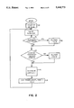
- FIG. 2 is a flow chart diagram of the main receiver loop logic of the receiver of FIG. 1;
- FIG. 3 is a flow chart diagram of the power saving module Power -- Smart -- Mode of the loop logic of FIG. 2;
- FIG. 4 is a flow chart diagram of the shut down module which conducts several status checks and performs acquisitions or reacquisitions before turning off the power to the RF circuitry of the receiver of FIG. 1;
- FIG. 5 illustrates the acquisition time cycles implemented to conserve battery power
- FIG. 6 is a flow chart diagram of the TURN -- OFF -- RF module of the receiver of FIG. 1;
- FIG. 7 is a flow chart diagram of the TURN -- ON -- RF module of the receiver of FIG. 1.
- FIG. 1 illustrates a GPS receiver 10 having an antenna 12, a radio frequency (RF) circuitry 14, a power supply 16, a power supply controller 18, an application specific integrated circuit (ASIC) 22, a random access memory (RAM) 23, a microprocessor 24, and a read only memory (ROM) 26.
- Antenna 12 receives navigation data signals from a plurality of satellites 32. A list of visible satellites is kept in the random access memory (RAM) 23 accessible to microprocessor 24 and ROM 26. Based on the current estimated position of the GPS receiver 10, the azimuth and the elevation of each satellite 32 in the constellation are computed. If the elevation angle of a satellite is positive and is greater than a mask angle, e.g., ten degrees, the satellite is considered visible.
- a mask angle e.g., ten degrees
- a satellite When a satellite first becomes visible, it is first included in the "to be acquired” list and an acquisition operation is executed to obtain the code phase and frequency of the satellite signals and collect the satellite's ephemeris.
- the visible satellite is added to the tracking list and maintained as under the "tracking state" when the signals received from the satellite are capable of generating measurements.
- Another situation is that a satellite which has been in the tracking state suddenly is lost because the signals are blocked by trees, tunnels, or buildings or because of excessive vehicle dynamics.
- the satellite is categorized as being in the "lost state”.
- the executable program residing in ROM 26, constantly checks the states of the satellites 32 and sets a flag for each satellite indicative of the current tracking state.
- RF circuitry 14 After the signals are received from the satellites 32, RF circuitry 14 first amplifies and then down converts the received RF signals to intermediate frequency (IF) signals.
- ASIC 22 includes a clock, data filters, demodulation circuits and integrators to simultaneously process through multiple channels the signals received from multiple satellites 32.
- ASIC 22 receives the IF signals from RF circuitry 14 and generates the pseudo-range (code phase) and the Doppler (frequency) measurements. These measurements are then used by microprocessor 24 for position fix computations.
- power supply controller 18 is under the control of an executable program residing in the ROM 26 to automatically adjust power level input to RF circuitry 14 to efficiently utilize the electric power provided by power supply 16.
- FIG. 2 is a flow chart diagram showing the logic sequence performed by the executable program residing in ROM 26 to control power supply 16.
- the ROM executable program includes a MAIN -- RCVR -- LOGIC module 40 which is initiated when receiver 10 is turned on by a step 44. With a step 46, a first check is made to determine if power supply 16 is connected to an external power source. Step 48 determines if power supply 16 is connected to an external power source, and if so, the power saving module POWER -- SMART -- MODE is not executed. If power supply 16 is not connected to an external power source, an operator of the GPS receiver is allowed an option to bypass the execution of the power saving program.
- the power saving module POWER -- SMART -- MODE is invoked in a step 54 when power supply 16 is not connected to an external power source and there is no user override command to bypass POWER -- SMART -- MODE power saving module.
- MAIN -- RCVR -- LOOP 40 is executed on a periodical basis such as once per every second to compute and update the position fix and to perform all other general functions of the receiver.
- the rate of position fix computations is basically fixed. A lower rate of position fix may be implemented when there is a need to save the battery power as determined by the logic below.
- MAIN -- RCVR -- LOOP 40 also allocates the visible satellites to the physical tracking channels and schedules the measurements to be taken for each satellite on the tracking list.
- FIG. 3 shows the steps executed by a power saving module POWER -- SMART -- MODE 60 within the program of ROM 26.
- a step 62 it first determines the on/off status of RF circuitry 14. If the RF circuitry 14 has the power turned off, the time that the power is off is first computed in a step 64 and the time off is compared to the length of time that the power is scheduled to be off, i.e., Toff in a step 66. If the time off is still within the time window of scheduled time off, the execution of POWER -- SMART -- MODE 60 is finished for this pass and returned to the beginning of MAIN -- RCVR -- LOOP 40.
- a subroutine TURN -- ON -- RF is called in a step 72 before returning in a step 74.
- the RF power is on
- a normal continuous power mode with position fix computation is executed in a step 78 proceeded with calling a shutdown logic module in a step 82.
- a test is made to determine how many good measurements, i.e., Ng, and how many missed measurements ,i.e. Nm, are processed by use of the signals received from the satellites in a step 92.
- Ng three-dimensional
- Nm missed measurements
- a shut down logic is called in a step 104 to turn the RF power off and compute a position fix in a step 106.
- a shut down logic module is called in the step 104 and a 2-D position fix is computed in the step 106. If computation of either 3-D or 2-D position is not achievable, then a check is first made to determine if VERICAL -- MOTION is true (step 109). A shutdown logic module is called if VERICAL -- MOTION is not true, otherwise a sequence of status checks are made to determine whether another RF burst will be performed (step 116) and the RF power will continue to stay on for one more RF burst.
- step 110 it is first determined if a three-dimensional fix is performed during the last RF burst and if there are three good measurements and there are at least four visible space vehicles. After satisfying the test conditions in step 110, one more RF burst is executed (step 116), otherwise further tests are performed in step 112 to determine if another RF burst should be executed, based on the test results from step 112, which determines whether a two-dimensional fix is likely to be successful. Only one more RF burst is allowed because QUICK -- BURST is set to true in step 116 and step 114 checks the value of QUICK -- BURST allowing the RF burst to be executed only once. The purpose of this logic is to attempt to at least obtain a two-dimensional fix even if there is vertical motion. The two-dimensional position fixes may not be sufficiently accurate but they can be useful for a GPS receiver to search for the satellites.
- each RF burst depends on the number of channels, the number of satellites and the length of time required for each satellite. For example, if GPS receiver 10 is a three-channel receiver and the time required for each satellite is 0.5 second, for a group of seven satellites an RF burst of 1.5 seconds,i.e. three times 0.5 seconds, is required, where three is the number of RF cycles needed to handle seven satellites with three channels. The length of the RF burst is thus designed to be sufficient to obtain a measurement from each satellite on the tracking list.
- FIG. 4 shows the logic of a SHUT -- DOWN Module 120 of the program of the ROM 26.
- SHUT -- DOWN module 120 When SHUT -- DOWN module 120 is called, it first sets QUICK -- CYCLE to a value of false (step 121) and checks whether the GPS receiver 10 knows the time in a step 122. If so, it checks if there is a position fix in a step 124, and if yes, if it is time to collect more almanac or ephemerals data in a step 126. The RF power is kept on if either of the test results for the first two enquiries, i.e. steps 122 or 124, are negative or the test result of the third enquiry, i.e. step 126, is positive.
- the age of the GPS almanac is checked periodically so that it is generally no more than twelve hours old. A flag is set if a new almanac is needed or if no almanac is available. Before the RF power is turned off, it is further tested if any visible space vehicles (SVS) which have not been acquired in a step 128, or if any SVS have been lost and whether a three-dimensional fix having a PDOP less than six (step 132) is not available with the current tracking list. If either of the above tests, i.e. steps 128 or 132, are true, a satellite acquisition cycle begins in a step 134 or 136 and a flag TRYING -- TO -- ACQ is set to 1, i.e.
- SVS visible space vehicles
- step 132 The purpose of step 132 is to save power when there are lost satellites but a good fix is available anyway.
- TURN -- RF -- OFF is then called to save power without trying to acquire the lost satellite. Otherwise,the acquisition is attempted for a maximum number of times, i.e. ON -- CNT -- MAX in step 142 and for a maximum number of cycles, i.e. CYCLE -- MAX in step 144 then the cycle is reset to zero in a step 146 and the RF power is turned off in a step 148.
- the power provided to RF circuitry 14 is turned on continuously for a period of ACQ -- ON -- TIME and then turned off until next RF ACQ -- CYCLE -- TIME is due (FIG. 5).
- a power saving is achieved because the RF power is not kept on through the entire acquisition time.
- a similar technique is used to acquire lost satellites. Reacquisition is treated slightly different because there is typically more information available about a lost satellite and it can be found in shorter length of time. The on and off times are set differently.
- An example of time limits for reacquisition is to maintain the power on for a time period of ten seconds and a cycle time of thirty seconds, while for initial acquisition the power is kept on for thirty seconds instead of ten and a cycle time of one hundred and twenty seconds instead of thirty.
- the acquisition and reacquisition operations are implemented in the SHUT -- DOWN logic. Before the RF circuitry 14 is turned off, attempts are made to acquire and reacquire the new or lost satellite. The acquisition or reacquisition are repeated a fixed number of cycles before proceeding to shutoff of the RF power. Since the SHUT -- DOWN logic is called repeatedly after a fixed time interval, acquisition and reacquisition will be attempted again if the previous operation fails. Since for a hand-held GPS receiver 10, the most frequent situation is the temporary loss of communication due to tree or building blockage, power saving is achieved by not keeping the RF power for the entire period of time when trying to reacquire the lost satellite.
- the power provided to RF circuitry 14 is turned off for a brief period of time which depends on the desired accuracy of the dead reckoning while the RF is off, the number of channels of the receiver, the distribution of the satellites to each channel, and the way that satellites are acquired.
- a turn off time of four to five seconds is generally acceptable.
- An important factor for power savings as taught in this invention is that the benefits of power savings are not disrupted when a satellite is lost or not yet acquired.
- the acquisition is accomplished with the RF power turned on only periodically. Meanwhile a test is made to determine if a 2-D solution is sufficient. No second attempt will be made if there is enough data for a 2-D position fix.
- the RF power is turned off right after the RF burst.
- FIG. 6 illustrates the logic of TURN -- OFF -- RF module 150 of the ROM 26. It first calculates the on time, i.e. Ton and off time Toff by first determining the maximum number of space vehicles (SVS) on each of the GPS receiver channels in a step 152 and Ton is the product of maximum number of SVS and the time per measurement which is fixed constant in a step 154. Toff is computed by subtracting the on time from the cycle time in a step 156.
- the RCVR tracking loops are put in an idle state in a step 158 and a hardware command is issued to activate a switch to shut off power to RF in a step 162 to save power.
- the state of RF power is set to off in a step 164 and the time when RF power is turned off is set to the current time in a step 166.
- the RF power will be turned on when a preset scheduled time off is up (see steps 66 and 72).
- DR dead reckoning
- ADAPTIVE a user optional input
- ADAPTIVE is TRUE and the speed of the GPS receiver is greater than a threshold speed S2, as determined by step 156-1, then the power to RF is kept on continuously and the execution of TURN -- OFF -- RF logic 150 is terminated and returned to the calling module (step 156-3).
- the RF power is kept on until the speed is reduced below S2 or when the user turns off the adaptive process by setting ADAPTIVE to FALSE.
- the speed of the receiver is less than S2 as determined by step 156-1, then the speed is compared to a first threshold speed, i.e. S1 in step 156-4. If the speed is greater or equal to S1, then a new cycle time which is half of the regular cycle time is used (step 156-5), otherwise a regular CYCLE -- TIME is kept unchanged and the program proceeded with step 156.
- FIG. 7 shows the logic operations of TURN -- ON -- RF module 170 of the ROM 26.
- a hardware command is first issued to activate the switch to turn on the RF power in a step 172.
- the RF burst is set to 1 (TRUE) to begin the RF burst cycle in a step 176 and the starting RF on time, i.e. t-on, is set to the current time in a step 178.
- the executable program residing in ROM 26 further computes a velocity vector of the GPS receiver 10 to determine the number of satellites and therefore position signals needed to compute a position fix, e.g., the number needed to satisfy a position accuracy requirement. A determination is made of the number of satellites that are providing position signals.
- the executable program turns-off power to the RF circuitry for a predetermined duration of time when the actual number of satellites equals or exceeds the required number of satellites, in order to conserve battery power.
- the executable program residing in ROM 26 preferably includes a routine for determining if the actual number of satellites visible is less than the number of satellites required for position signals, e.g., a two dimensional position fix may be sufficient and available.
- the executable program residing in ROM 26 stores a plurality of historical position fix data and a list of the visible satellites. If the actual number of satellites that position signals are being received from is less than a required number, the history of position fix data and the list of the visible satellites is used to determine if an additional RF burst should be performed to add the available measurement data.
Abstract
Description
Claims (9)
Priority Applications (1)
| Application Number | Priority Date | Filing Date | Title |
|---|---|---|---|
| US07/831,870 US5448773A (en) | 1992-02-05 | 1992-02-05 | Long life portable global position system receiver |
Applications Claiming Priority (1)
| Application Number | Priority Date | Filing Date | Title |
|---|---|---|---|
| US07/831,870 US5448773A (en) | 1992-02-05 | 1992-02-05 | Long life portable global position system receiver |
Publications (1)
| Publication Number | Publication Date |
|---|---|
| US5448773A true US5448773A (en) | 1995-09-05 |
Family
ID=25260060
Family Applications (1)
| Application Number | Title | Priority Date | Filing Date |
|---|---|---|---|
| US07/831,870 Expired - Fee Related US5448773A (en) | 1992-02-05 | 1992-02-05 | Long life portable global position system receiver |
Country Status (1)
| Country | Link |
|---|---|
| US (1) | US5448773A (en) |
Cited By (87)
| Publication number | Priority date | Publication date | Assignee | Title |
|---|---|---|---|---|
| US5592173A (en) * | 1994-07-18 | 1997-01-07 | Trimble Navigation, Ltd | GPS receiver having a low power standby mode |
| WO1997014049A2 (en) * | 1995-10-09 | 1997-04-17 | Snaptrack, Inc. | Gps receiver and method for processing gps signals |
| WO1997040398A2 (en) * | 1996-04-25 | 1997-10-30 | Sirf Technology, Inc. | Spread spectrum receiver with multi-bit correlator |
| WO1998002758A1 (en) * | 1996-07-12 | 1998-01-22 | General Electric Company | Power efficient receiver |
| WO1998002984A2 (en) * | 1996-07-12 | 1998-01-22 | General Electric Company | Low power signal processing for spread spectrum receivers |
| US5781156A (en) * | 1995-10-09 | 1998-07-14 | Snaptrack, Inc. | GPS receiver and method for processing GPS signals |
| US5825327A (en) * | 1996-03-08 | 1998-10-20 | Snaptrack, Inc. | GPS receivers and garments containing GPS receivers and methods for using these GPS receivers |
| US5831574A (en) * | 1996-03-08 | 1998-11-03 | Snaptrack, Inc. | Method and apparatus for determining the location of an object which may have an obstructed view of the sky |
| US5841396A (en) * | 1996-03-08 | 1998-11-24 | Snaptrack, Inc. | GPS receiver utilizing a communication link |
| US5845203A (en) * | 1996-01-25 | 1998-12-01 | Aertis Cormmunications | Remote access application messaging wireless method |
| US5884199A (en) * | 1995-11-13 | 1999-03-16 | Kabushiki Kaisha Kenwood | Portable wireless receiver |
| US5884214A (en) * | 1996-09-06 | 1999-03-16 | Snaptrack, Inc. | GPS receiver and method for processing GPS signals |
| US5889474A (en) * | 1992-05-18 | 1999-03-30 | Aeris Communications, Inc. | Method and apparatus for transmitting subject status information over a wireless communications network |
| US5897605A (en) * | 1996-03-15 | 1999-04-27 | Sirf Technology, Inc. | Spread spectrum receiver with fast signal reacquisition |
| US5901171A (en) * | 1996-03-15 | 1999-05-04 | Sirf Technology, Inc. | Triple multiplexing spread spectrum receiver |
| US5995042A (en) * | 1997-01-02 | 1999-11-30 | Motorola, Inc. | Spoofer detection power management for GPS receivers |
| US5999808A (en) * | 1995-12-12 | 1999-12-07 | Aeris Communications, Inc. | Wireless gaming method |
| US6007372A (en) * | 1996-09-18 | 1999-12-28 | Delorme Publishing Co. | GPS power/data cable system |
| US6016119A (en) * | 1995-10-09 | 2000-01-18 | Snaptrack, Inc. | Method and apparatus for determining the location of an object which may have an obstructed view of the sky |
| US6018704A (en) * | 1996-04-25 | 2000-01-25 | Sirf Tech Inc | GPS receiver |
| US6041280A (en) * | 1996-03-15 | 2000-03-21 | Sirf Technology, Inc. | GPS car navigation system |
| US6047017A (en) * | 1996-04-25 | 2000-04-04 | Cahn; Charles R. | Spread spectrum receiver with multi-path cancellation |
| US6061018A (en) * | 1998-05-05 | 2000-05-09 | Snaptrack, Inc. | Method and system for using altitude information in a satellite positioning system |
| US6104340A (en) * | 1995-10-09 | 2000-08-15 | Snaptrack, Inc. | GPS receiver and method for processing GPS signals |
| US6125325A (en) * | 1996-04-25 | 2000-09-26 | Sirf Technology, Inc. | GPS receiver with cross-track hold |
| US6141570A (en) * | 1998-08-26 | 2000-10-31 | Ericsson Inc. | System and method for conserving battery energy in a wireless telephone with an integral global positioning system |
| US6144859A (en) * | 1993-08-27 | 2000-11-07 | Aeris Communications, Inc. | Wireless cellular communicator system and apparatus |
| US6147644A (en) * | 1996-12-30 | 2000-11-14 | Southwest Research Institute | Autonomous geolocation and message communication system and method |
| US6198765B1 (en) | 1996-04-25 | 2001-03-06 | Sirf Technologies, Inc. | Spread spectrum receiver with multi-path correction |
| US6208290B1 (en) | 1996-03-08 | 2001-03-27 | Snaptrack, Inc. | GPS receiver utilizing a communication link |
| US20010002203A1 (en) * | 1996-04-25 | 2001-05-31 | Cahn Charles R. | Spread spectrum receiver with multi-path correction |
| US6249542B1 (en) | 1997-03-28 | 2001-06-19 | Sirf Technology, Inc. | Multipath processing for GPS receivers |
| US6259399B1 (en) | 1995-10-09 | 2001-07-10 | Snaptrack, Inc. | GPS receivers and garments containing GPS receivers and methods for using these GPS receivers |
| US6282231B1 (en) | 1999-12-14 | 2001-08-28 | Sirf Technology, Inc. | Strong signal cancellation to enhance processing of weak spread spectrum signal |
| US6285868B1 (en) | 1993-08-27 | 2001-09-04 | Aeris Communications, Inc. | Wireless communications application specific enabling method and apparatus |
| US6392591B1 (en) * | 2001-03-22 | 2002-05-21 | Evermore Technology, Inc. | Global positioning system |
| US6393046B1 (en) | 1996-04-25 | 2002-05-21 | Sirf Technology, Inc. | Spread spectrum receiver with multi-bit correlator |
| US20020067306A1 (en) * | 2000-11-16 | 2002-06-06 | Matsushita Electric Industrial Co., Ltd. | Satellite signal receiver |
| US6438381B1 (en) * | 2000-06-08 | 2002-08-20 | Motorola, Inc. | Method and apparatus for location determination of a cellular telephone |
| US6492941B1 (en) | 1999-05-07 | 2002-12-10 | Garmin Corporation | Combined global positioning system receiver and radio |
| US20030050038A1 (en) * | 2001-08-17 | 2003-03-13 | Luther Haave | Method and system for asset tracking |
| US6590525B2 (en) * | 2000-02-24 | 2003-07-08 | Koninklijke Philips Electronics N.V. | GPS receiver and mobile unit incorporating the same |
| WO2003025618A3 (en) * | 2001-09-14 | 2003-08-14 | Sirf Tech Inc | Advanced power management for satellite positioning system |
| US20040029593A1 (en) * | 2002-08-09 | 2004-02-12 | Skinner Davey N. | Global positioning system receiver with high density memory storage |
| WO2004047309A2 (en) * | 2002-11-15 | 2004-06-03 | Interdigital Technology Corporation | Wireless transmit/receive units having multiple receivers and methods |
| US6768450B1 (en) | 2002-11-07 | 2004-07-27 | Garmin Ltd. | System and method for wirelessly linking a GPS device and a portable electronic device |
| US6774838B2 (en) * | 2002-12-27 | 2004-08-10 | Kinpo Electronics, Inc. | Power saving device and method for GPS receiver |
| US20040192345A1 (en) * | 2003-03-24 | 2004-09-30 | Osborn William R. | Methods, systems and computer program products for providing location determination information to an assisted location service |
| US6816782B1 (en) | 2002-10-10 | 2004-11-09 | Garmin Ltd. | Apparatus, systems and methods for navigation data transfer between portable devices |
| US20040263386A1 (en) * | 2003-06-26 | 2004-12-30 | King Thomas M. | Satellite positioning system receivers and methods |
| US6839547B2 (en) * | 2000-03-30 | 2005-01-04 | Cellguide Ltd. | Enhanced GPS receiver utilizing wireless infrastructure |
| US20050070223A1 (en) * | 2003-09-25 | 2005-03-31 | Camp William O. | Mobile terminals and methods for estimating GPS time based on timing of information from a wireless communication system |
| US20050114721A1 (en) * | 2003-11-25 | 2005-05-26 | Kameran Azadet | Method and apparatus for power management using transmission mode with reduced power |
| US20060034354A1 (en) * | 2004-08-16 | 2006-02-16 | Camp William O Jr | Apparatus, methods and computer program products for positioning system signal processing using parallel computational techniques |
| US20060033658A1 (en) * | 2004-08-16 | 2006-02-16 | Camp William O Jr | Apparatus, methods and computer program products for GPS signal acquisition using an adaptive search engine |
| US7061972B1 (en) | 2002-04-04 | 2006-06-13 | Best Gregory C | GPS receiver having dynamic correlator allocation between a memory-enhanced channel for acquisition and standard channels for tracking |
| US20060153114A1 (en) * | 2004-11-26 | 2006-07-13 | Matsushita Electric Industrial Co., Ltd. | Communication system, communication terminal, and communication method |
| US7142900B1 (en) | 2001-11-01 | 2006-11-28 | Garmin Ltd. | Combined global positioning system receiver and radio |
| US20070021134A1 (en) * | 2005-07-21 | 2007-01-25 | Henry Liou | Position reporting microphone |
| US7196659B1 (en) | 1999-05-07 | 2007-03-27 | Garmin Corporation | Combined global positioning system receiver and radio |
| US7330150B1 (en) | 1999-05-07 | 2008-02-12 | Garmin Corporation | Combined global positioning system receiver and radio |
| US7349705B1 (en) * | 1999-07-29 | 2008-03-25 | Bryan Holland | Wireless remote location system and method |
| US20080167810A1 (en) * | 2007-01-10 | 2008-07-10 | Lucas Wildervanck | Navigation device and method for early instruction output |
| US7453956B2 (en) | 2004-08-16 | 2008-11-18 | Sony Ericsson Mobile Communications Ab | Apparatus, methods and computer program products for signal acquisition using common demodulation templates |
| WO2008151605A1 (en) * | 2007-06-14 | 2008-12-18 | Navigon Ag | Method for operating a navigation device |
| US20090016167A1 (en) * | 2007-07-09 | 2009-01-15 | Seiko Epson Corporation | Time Adjustment Device, Timekeeping Device with a Time Adjustment Device, and a Time Adjustment Method |
| USRE40642E1 (en) | 1995-05-31 | 2009-02-17 | General Electric Company | Reduced-power GPS-based system for tracking multiple objects from a central location |
| US20090098880A1 (en) * | 2007-10-16 | 2009-04-16 | Sony Ericsson Mobile Communications Ab | Mobile terminals and methods for regulating power-on/off of a gps positioning circuit |
| US20100045516A1 (en) * | 2007-10-23 | 2010-02-25 | Seiko Epson Corporation | Positioning method, positioning device, and electronic instrument |
| US20100045519A1 (en) * | 2008-08-22 | 2010-02-25 | Samsung Electronics Co., Ltd. | Method of recording position of mobile device, mobile device and recording medium thereof |
| WO2010037416A1 (en) * | 2008-10-01 | 2010-04-08 | Nokia Corporation | Managing the measurement of signals |
| EP2241904A1 (en) * | 2009-03-30 | 2010-10-20 | econes Gmbh | Device for locating a mobile object and method for operating same |
| US7925320B2 (en) | 2006-03-06 | 2011-04-12 | Garmin Switzerland Gmbh | Electronic device mount |
| US20120062414A1 (en) * | 2010-09-15 | 2012-03-15 | Casio Computer Co., Ltd. | Positioning apparatus, positioning method, and storage medium for measuring position using both autonomous navigation and gps |
| US20130324098A1 (en) * | 2012-06-05 | 2013-12-05 | Patrick S. Piemonte | Methods and Apparatus for Determining Environmental Factors to Modify Hardware or System Operation |
| WO2015069510A3 (en) * | 2013-11-06 | 2015-06-25 | Qualcomm Incorporated | Low power positioning techniques for mobile devices |
| US9222787B2 (en) | 2012-06-05 | 2015-12-29 | Apple Inc. | System and method for acquiring map portions based on expected signal strength of route segments |
| US9432961B2 (en) | 2013-01-16 | 2016-08-30 | Apple Inc. | Location-assisted service capability monitoring |
| US9441975B2 (en) | 2012-06-05 | 2016-09-13 | Apple Inc. | System and method for generating signal coverage information from client metrics |
| US9596670B2 (en) | 2013-01-16 | 2017-03-14 | Apple Inc. | Location assisted service capability monitoring |
| US9606241B2 (en) | 2013-02-21 | 2017-03-28 | Apple Inc. | Sensor-assisted location fix |
| US20200064491A1 (en) * | 2002-04-24 | 2020-02-27 | Ipventure, Inc. | Method and apparatus for intelligent acquisition of position information |
| US10827298B2 (en) | 2000-02-28 | 2020-11-03 | Ipventure, Inc. | Method and apparatus for location identification and presentation |
| US11032677B2 (en) | 2002-04-24 | 2021-06-08 | Ipventure, Inc. | Method and system for enhanced messaging using sensor input |
| US11112254B2 (en) | 2012-08-31 | 2021-09-07 | Apple Inc. | Navigation system acquisition and use of cellular coverage map data |
| US11238398B2 (en) | 2002-04-24 | 2022-02-01 | Ipventure, Inc. | Tracking movement of objects and notifications therefor |
| US11330419B2 (en) | 2000-02-28 | 2022-05-10 | Ipventure, Inc. | Method and system for authorized location monitoring |
Citations (8)
| Publication number | Priority date | Publication date | Assignee | Title |
|---|---|---|---|---|
| US4755816A (en) * | 1986-10-29 | 1988-07-05 | Motorola Inc. | Battery saving method for a selective call radio paging receiver |
| US4962523A (en) * | 1988-01-29 | 1990-10-09 | Nec Corporation | Radio telephone set used as portable set and vehicle-mounted set |
| US5095308A (en) * | 1990-01-09 | 1992-03-10 | Southern Marine Research, Inc. | Transceiver with battery saver and method of using same |
| US5101510A (en) * | 1988-06-18 | 1992-03-31 | Robert Bosch Gmbh | Energy conserving stand-by function in radio traffic report receiver |
| US5119504A (en) * | 1990-07-19 | 1992-06-02 | Motorola, Inc. | Position aided subscriber unit for a satellite cellular system |
| US5161255A (en) * | 1990-01-26 | 1992-11-03 | Pioneer Electronic Corporation | Motor vehicle-mounted radio wave receiving gps apparatus requiring no drill holes for mounting |
| US5204986A (en) * | 1988-02-25 | 1993-04-20 | Kabushiki Kaisha Toahiba | Battery powered radio devices having a battery saving function |
| US5222242A (en) * | 1990-09-28 | 1993-06-22 | International Business Machines Corp. | System for locating a node containing a requested resource and for selectively verifying the presence of the resource at the node |
-
1992
- 1992-02-05 US US07/831,870 patent/US5448773A/en not_active Expired - Fee Related
Patent Citations (8)
| Publication number | Priority date | Publication date | Assignee | Title |
|---|---|---|---|---|
| US4755816A (en) * | 1986-10-29 | 1988-07-05 | Motorola Inc. | Battery saving method for a selective call radio paging receiver |
| US4962523A (en) * | 1988-01-29 | 1990-10-09 | Nec Corporation | Radio telephone set used as portable set and vehicle-mounted set |
| US5204986A (en) * | 1988-02-25 | 1993-04-20 | Kabushiki Kaisha Toahiba | Battery powered radio devices having a battery saving function |
| US5101510A (en) * | 1988-06-18 | 1992-03-31 | Robert Bosch Gmbh | Energy conserving stand-by function in radio traffic report receiver |
| US5095308A (en) * | 1990-01-09 | 1992-03-10 | Southern Marine Research, Inc. | Transceiver with battery saver and method of using same |
| US5161255A (en) * | 1990-01-26 | 1992-11-03 | Pioneer Electronic Corporation | Motor vehicle-mounted radio wave receiving gps apparatus requiring no drill holes for mounting |
| US5119504A (en) * | 1990-07-19 | 1992-06-02 | Motorola, Inc. | Position aided subscriber unit for a satellite cellular system |
| US5222242A (en) * | 1990-09-28 | 1993-06-22 | International Business Machines Corp. | System for locating a node containing a requested resource and for selectively verifying the presence of the resource at the node |
Cited By (179)
| Publication number | Priority date | Publication date | Assignee | Title |
|---|---|---|---|---|
| US5889474A (en) * | 1992-05-18 | 1999-03-30 | Aeris Communications, Inc. | Method and apparatus for transmitting subject status information over a wireless communications network |
| US6144859A (en) * | 1993-08-27 | 2000-11-07 | Aeris Communications, Inc. | Wireless cellular communicator system and apparatus |
| US6285868B1 (en) | 1993-08-27 | 2001-09-04 | Aeris Communications, Inc. | Wireless communications application specific enabling method and apparatus |
| US5592173A (en) * | 1994-07-18 | 1997-01-07 | Trimble Navigation, Ltd | GPS receiver having a low power standby mode |
| USRE40642E1 (en) | 1995-05-31 | 2009-02-17 | General Electric Company | Reduced-power GPS-based system for tracking multiple objects from a central location |
| CN101093254A (en) * | 1995-10-09 | 2007-12-26 | 快速追踪有限公司 | GPS receiver and method for processing GPS signals |
| US6133871A (en) * | 1995-10-09 | 2000-10-17 | Snaptrack, Inc. | GPS receiver having power management |
| CN101093254B (en) * | 1995-10-09 | 2014-10-22 | 快速追踪有限公司 | GPS receiver and method for processing GPS signals |
| US5781156A (en) * | 1995-10-09 | 1998-07-14 | Snaptrack, Inc. | GPS receiver and method for processing GPS signals |
| US6259399B1 (en) | 1995-10-09 | 2001-07-10 | Snaptrack, Inc. | GPS receivers and garments containing GPS receivers and methods for using these GPS receivers |
| US6542821B2 (en) | 1995-10-09 | 2003-04-01 | Snaptrack, Inc. | GPS receiver and method for processing GPS signals |
| US6400314B1 (en) | 1995-10-09 | 2002-06-04 | Qualcomm Incorporated | GPS receiver utilizing a communication link |
| US6016119A (en) * | 1995-10-09 | 2000-01-18 | Snaptrack, Inc. | Method and apparatus for determining the location of an object which may have an obstructed view of the sky |
| EP2113782A3 (en) * | 1995-10-09 | 2010-01-27 | Snaptrack, Inc. | GPS mobile unit having a reduced power state |
| US6421002B2 (en) | 1995-10-09 | 2002-07-16 | Snaptrack, Inc. | GPS receiver utilizing a communication link |
| WO1997014049A3 (en) * | 1995-10-09 | 1997-06-19 | Snaptrack Inc | Gps receiver and method for processing gps signals |
| US6104340A (en) * | 1995-10-09 | 2000-08-15 | Snaptrack, Inc. | GPS receiver and method for processing GPS signals |
| US6064336A (en) * | 1995-10-09 | 2000-05-16 | Snaptrack, Inc. | GPS receiver utilizing a communication link |
| WO1997014049A2 (en) * | 1995-10-09 | 1997-04-17 | Snaptrack, Inc. | Gps receiver and method for processing gps signals |
| US5884199A (en) * | 1995-11-13 | 1999-03-16 | Kabushiki Kaisha Kenwood | Portable wireless receiver |
| US5999808A (en) * | 1995-12-12 | 1999-12-07 | Aeris Communications, Inc. | Wireless gaming method |
| US5845203A (en) * | 1996-01-25 | 1998-12-01 | Aertis Cormmunications | Remote access application messaging wireless method |
| US5841396A (en) * | 1996-03-08 | 1998-11-24 | Snaptrack, Inc. | GPS receiver utilizing a communication link |
| US5831574A (en) * | 1996-03-08 | 1998-11-03 | Snaptrack, Inc. | Method and apparatus for determining the location of an object which may have an obstructed view of the sky |
| US5825327A (en) * | 1996-03-08 | 1998-10-20 | Snaptrack, Inc. | GPS receivers and garments containing GPS receivers and methods for using these GPS receivers |
| US6208290B1 (en) | 1996-03-08 | 2001-03-27 | Snaptrack, Inc. | GPS receiver utilizing a communication link |
| US6292749B2 (en) | 1996-03-15 | 2001-09-18 | Sirf Technology, Inc. | GPS receiver with cross-track hold |
| US6041280A (en) * | 1996-03-15 | 2000-03-21 | Sirf Technology, Inc. | GPS car navigation system |
| US7295633B2 (en) | 1996-03-15 | 2007-11-13 | Sirf Technology, Inc. | Triple multiplexing spread spectrum receiver |
| US5901171A (en) * | 1996-03-15 | 1999-05-04 | Sirf Technology, Inc. | Triple multiplexing spread spectrum receiver |
| US5897605A (en) * | 1996-03-15 | 1999-04-27 | Sirf Technology, Inc. | Spread spectrum receiver with fast signal reacquisition |
| US6522682B1 (en) | 1996-03-15 | 2003-02-18 | Sirf Technology, Inc. | Triple multiplexing spread spectrum receiver |
| US6788735B2 (en) | 1996-03-15 | 2004-09-07 | Sirf Technology, Inc. | Triple multiplexing spread spectrum receiver |
| US6198765B1 (en) | 1996-04-25 | 2001-03-06 | Sirf Technologies, Inc. | Spread spectrum receiver with multi-path correction |
| US6633814B2 (en) | 1996-04-25 | 2003-10-14 | Sirf Technology, Inc. | GPS system for navigating a vehicle |
| US6574558B2 (en) | 1996-04-25 | 2003-06-03 | Sirf Technology, Inc. | GPS receiver with cross-track hold |
| US6917644B2 (en) | 1996-04-25 | 2005-07-12 | Sirf Technology, Inc. | Spread spectrum receiver with multi-path correction |
| US6236937B1 (en) | 1996-04-25 | 2001-05-22 | Sirf Technology, Inc. | GPS receiver with cross-track hold |
| US20010002203A1 (en) * | 1996-04-25 | 2001-05-31 | Cahn Charles R. | Spread spectrum receiver with multi-path correction |
| US6125325A (en) * | 1996-04-25 | 2000-09-26 | Sirf Technology, Inc. | GPS receiver with cross-track hold |
| US6393046B1 (en) | 1996-04-25 | 2002-05-21 | Sirf Technology, Inc. | Spread spectrum receiver with multi-bit correlator |
| US6421609B2 (en) | 1996-04-25 | 2002-07-16 | Sirf Technology, Inc. | GPS receiver with cross-track hold |
| WO1997040398A3 (en) * | 1996-04-25 | 1998-02-26 | Sirf Tech Inc | Spread spectrum receiver with multi-bit correlator |
| US6047017A (en) * | 1996-04-25 | 2000-04-04 | Cahn; Charles R. | Spread spectrum receiver with multi-path cancellation |
| US6018704A (en) * | 1996-04-25 | 2000-01-25 | Sirf Tech Inc | GPS receiver |
| US6400753B1 (en) | 1996-04-25 | 2002-06-04 | Sirf Technology, Inc. | Pseudo-noise correlator for a GPS spread spectrum receiver |
| WO1997040398A2 (en) * | 1996-04-25 | 1997-10-30 | Sirf Technology, Inc. | Spread spectrum receiver with multi-bit correlator |
| US6028887A (en) * | 1996-07-12 | 2000-02-22 | General Electric Company | Power efficient receiver |
| US6028883A (en) * | 1996-07-12 | 2000-02-22 | General Electric Company | Low power signal processing for spread spectrum receivers |
| WO1998002758A1 (en) * | 1996-07-12 | 1998-01-22 | General Electric Company | Power efficient receiver |
| WO1998002984A3 (en) * | 1996-07-12 | 1998-05-07 | Gen Electric | Low power signal processing for spread spectrum receivers |
| WO1998002984A2 (en) * | 1996-07-12 | 1998-01-22 | General Electric Company | Low power signal processing for spread spectrum receivers |
| US6272430B1 (en) | 1996-09-06 | 2001-08-07 | Snaptrack, Inc. | GPS receiver and method for processing GPS signals |
| US5884214A (en) * | 1996-09-06 | 1999-03-16 | Snaptrack, Inc. | GPS receiver and method for processing GPS signals |
| US6725159B2 (en) | 1996-09-06 | 2004-04-20 | Snaptrack Incorporated | GPS receiver and method for processing GPS signals |
| US6007372A (en) * | 1996-09-18 | 1999-12-28 | Delorme Publishing Co. | GPS power/data cable system |
| US6147644A (en) * | 1996-12-30 | 2000-11-14 | Southwest Research Institute | Autonomous geolocation and message communication system and method |
| US5995042A (en) * | 1997-01-02 | 1999-11-30 | Motorola, Inc. | Spoofer detection power management for GPS receivers |
| US6466612B2 (en) | 1997-03-28 | 2002-10-15 | Sirf Technology, Inc. | Multipath processing for GPS receivers |
| US20040184516A1 (en) * | 1997-03-28 | 2004-09-23 | Sanjai Kohli | Multipath processing for GPS receivers |
| US7301992B2 (en) | 1997-03-28 | 2007-11-27 | Sirf Technology, Inc. | Multipath processing for GPS receivers |
| US6249542B1 (en) | 1997-03-28 | 2001-06-19 | Sirf Technology, Inc. | Multipath processing for GPS receivers |
| US6760364B2 (en) | 1997-03-28 | 2004-07-06 | Sirf Technology, Inc. | Multipath processing for GPS receivers |
| US6061018A (en) * | 1998-05-05 | 2000-05-09 | Snaptrack, Inc. | Method and system for using altitude information in a satellite positioning system |
| US6307504B1 (en) | 1998-05-05 | 2001-10-23 | Snaptrack, Inc. | Method and system for using altitude information in a satellite positioning system |
| US6141570A (en) * | 1998-08-26 | 2000-10-31 | Ericsson Inc. | System and method for conserving battery energy in a wireless telephone with an integral global positioning system |
| US6492941B1 (en) | 1999-05-07 | 2002-12-10 | Garmin Corporation | Combined global positioning system receiver and radio |
| US7456784B2 (en) | 1999-05-07 | 2008-11-25 | Garmin Corporation | Combined global positioning system receiver and radio |
| US7330150B1 (en) | 1999-05-07 | 2008-02-12 | Garmin Corporation | Combined global positioning system receiver and radio |
| US7196659B1 (en) | 1999-05-07 | 2007-03-27 | Garmin Corporation | Combined global positioning system receiver and radio |
| US7349705B1 (en) * | 1999-07-29 | 2008-03-25 | Bryan Holland | Wireless remote location system and method |
| US20080220794A1 (en) * | 1999-07-29 | 2008-09-11 | Bryan Holland | Wireless remote location system and method |
| US8238934B2 (en) | 1999-07-29 | 2012-08-07 | Bryan Holland | Wireless remote location system and method |
| US6282231B1 (en) | 1999-12-14 | 2001-08-28 | Sirf Technology, Inc. | Strong signal cancellation to enhance processing of weak spread spectrum signal |
| US6590525B2 (en) * | 2000-02-24 | 2003-07-08 | Koninklijke Philips Electronics N.V. | GPS receiver and mobile unit incorporating the same |
| US11330419B2 (en) | 2000-02-28 | 2022-05-10 | Ipventure, Inc. | Method and system for authorized location monitoring |
| US10827298B2 (en) | 2000-02-28 | 2020-11-03 | Ipventure, Inc. | Method and apparatus for location identification and presentation |
| US10873828B2 (en) | 2000-02-28 | 2020-12-22 | Ipventure, Inc. | Method and apparatus identifying and presenting location and location-related information |
| US6839547B2 (en) * | 2000-03-30 | 2005-01-04 | Cellguide Ltd. | Enhanced GPS receiver utilizing wireless infrastructure |
| US6438381B1 (en) * | 2000-06-08 | 2002-08-20 | Motorola, Inc. | Method and apparatus for location determination of a cellular telephone |
| US20020067306A1 (en) * | 2000-11-16 | 2002-06-06 | Matsushita Electric Industrial Co., Ltd. | Satellite signal receiver |
| US7065320B2 (en) * | 2000-11-16 | 2006-06-20 | Matsushita Electric Industrial Co., Ltd. | Satellite signal receiver |
| US6686877B2 (en) * | 2000-11-16 | 2004-02-03 | Matsushita Electric Industrial Co., Ltd. | Satellite signal receiver |
| US20040087267A1 (en) * | 2000-11-16 | 2004-05-06 | Matsushita Electric Industrial Co., Ltd. | Satellite signal receiver |
| US6392591B1 (en) * | 2001-03-22 | 2002-05-21 | Evermore Technology, Inc. | Global positioning system |
| US20030050038A1 (en) * | 2001-08-17 | 2003-03-13 | Luther Haave | Method and system for asset tracking |
| US7468659B2 (en) | 2001-08-17 | 2008-12-23 | Luther Haave | Method of configuring a tracking device |
| US20070026842A1 (en) * | 2001-08-17 | 2007-02-01 | Longview Advantage, Inc. | Method of configuring a tracking device |
| US7801506B2 (en) | 2001-08-17 | 2010-09-21 | Luther Haave | System for asset tracking |
| US20070021100A1 (en) * | 2001-08-17 | 2007-01-25 | Longview Advantage, Inc. | System for asset tracking |
| US7171187B2 (en) | 2001-08-17 | 2007-01-30 | Longview Advantage, Inc | Method and system for asset tracking |
| WO2003025618A3 (en) * | 2001-09-14 | 2003-08-14 | Sirf Tech Inc | Advanced power management for satellite positioning system |
| US7962165B2 (en) | 2001-11-01 | 2011-06-14 | Garmin Switzerland Gmbh | Combined global positioning system receiver and radio |
| US7729684B1 (en) | 2001-11-01 | 2010-06-01 | Garmin Ltd. | Combined global positioning system receiver and radio |
| US7142900B1 (en) | 2001-11-01 | 2006-11-28 | Garmin Ltd. | Combined global positioning system receiver and radio |
| US20100203849A1 (en) * | 2001-11-01 | 2010-08-12 | Garmin Ltd. | Combined global positioning system receiver and radio |
| US7061972B1 (en) | 2002-04-04 | 2006-06-13 | Best Gregory C | GPS receiver having dynamic correlator allocation between a memory-enhanced channel for acquisition and standard channels for tracking |
| US11067704B2 (en) | 2002-04-24 | 2021-07-20 | Ipventure, Inc. | Method and apparatus for intelligent acquisition of position information |
| US11054527B2 (en) | 2002-04-24 | 2021-07-06 | Ipventure, Inc. | Method and apparatus for intelligent acquisition of position information |
| US11238398B2 (en) | 2002-04-24 | 2022-02-01 | Ipventure, Inc. | Tracking movement of objects and notifications therefor |
| US11218848B2 (en) | 2002-04-24 | 2022-01-04 | Ipventure, Inc. | Messaging enhancement with location information |
| US11368808B2 (en) | 2002-04-24 | 2022-06-21 | Ipventure, Inc. | Method and apparatus for identifying and presenting location and location-related information |
| US11032677B2 (en) | 2002-04-24 | 2021-06-08 | Ipventure, Inc. | Method and system for enhanced messaging using sensor input |
| US11041960B2 (en) * | 2002-04-24 | 2021-06-22 | Ipventure, Inc. | Method and apparatus for intelligent acquisition of position information |
| US20200064491A1 (en) * | 2002-04-24 | 2020-02-27 | Ipventure, Inc. | Method and apparatus for intelligent acquisition of position information |
| US11249196B2 (en) | 2002-04-24 | 2022-02-15 | Ipventure, Inc. | Method and apparatus for intelligent acquisition of position information |
| US10761214B2 (en) | 2002-04-24 | 2020-09-01 | Ipventure, Inc. | Method and apparatus for intelligent acquisition of position information |
| US11418905B2 (en) | 2002-04-24 | 2022-08-16 | Ipventure, Inc. | Method and apparatus for identifying and presenting location and location-related information |
| US11915186B2 (en) | 2002-04-24 | 2024-02-27 | Ipventure, Inc. | Personalized medical monitoring and notifications therefor |
| US11308441B2 (en) | 2002-04-24 | 2022-04-19 | Ipventure, Inc. | Method and system for tracking and monitoring assets |
| US20040029593A1 (en) * | 2002-08-09 | 2004-02-12 | Skinner Davey N. | Global positioning system receiver with high density memory storage |
| US6816782B1 (en) | 2002-10-10 | 2004-11-09 | Garmin Ltd. | Apparatus, systems and methods for navigation data transfer between portable devices |
| US7034747B1 (en) | 2002-11-07 | 2006-04-25 | Garmin Ltd. | System and method for wirelessly linking a GPS device and a portable electronic device |
| US6768450B1 (en) | 2002-11-07 | 2004-07-27 | Garmin Ltd. | System and method for wirelessly linking a GPS device and a portable electronic device |
| WO2004047309A3 (en) * | 2002-11-15 | 2004-07-22 | Interdigital Tech Corp | Wireless transmit/receive units having multiple receivers and methods |
| AU2003290783B2 (en) * | 2002-11-15 | 2007-03-08 | Interdigital Technology Corporation | Wireless transmit/receive units having multiple receivers and methods |
| US20040106441A1 (en) * | 2002-11-15 | 2004-06-03 | Interdigital Technology Corporation | Wireless transmit/receive units having multiple receivers and methods |
| US7343180B2 (en) | 2002-11-15 | 2008-03-11 | Interdigital Technology Corporation | Wireless transmit/receive units having multiple receivers and methods |
| WO2004047309A2 (en) * | 2002-11-15 | 2004-06-03 | Interdigital Technology Corporation | Wireless transmit/receive units having multiple receivers and methods |
| JP2009213157A (en) * | 2002-11-15 | 2009-09-17 | Interdigital Technol Corp | Wireless transmission/reception unit having multiple receivers, and method |
| US6774838B2 (en) * | 2002-12-27 | 2004-08-10 | Kinpo Electronics, Inc. | Power saving device and method for GPS receiver |
| US20040192345A1 (en) * | 2003-03-24 | 2004-09-30 | Osborn William R. | Methods, systems and computer program products for providing location determination information to an assisted location service |
| US8010124B2 (en) | 2003-03-24 | 2011-08-30 | Sony Ericsson Mobile Communications Ab | Methods, systems and computer program products for providing location determination information to an assisted location service |
| EP2309290A1 (en) * | 2003-06-26 | 2011-04-13 | Motorola Mobility, Inc. | Satellite positioning system receivers and methods |
| US20060181452A1 (en) * | 2003-06-26 | 2006-08-17 | King Thomas M | Satellite positioning system receivers and methods |
| US7969356B2 (en) | 2003-06-26 | 2011-06-28 | Motorola Mobility, Inc. | Satellite positioning system receivers and methods |
| US7336224B2 (en) * | 2003-06-26 | 2008-02-26 | Motorola, Inc. | Satellite positioning system receivers and methods |
| US20040263386A1 (en) * | 2003-06-26 | 2004-12-30 | King Thomas M. | Satellite positioning system receivers and methods |
| US20060181453A1 (en) * | 2003-06-26 | 2006-08-17 | King Thomas M | Satellite positioning system receivers and methods |
| US20070247355A1 (en) * | 2003-06-26 | 2007-10-25 | King Thomas M | Satellite positioning system receivers and methods |
| WO2005033729A3 (en) * | 2003-06-26 | 2006-04-13 | Motorola Inc | Satellite positioning system receivers and methods |
| US7298321B2 (en) | 2003-06-26 | 2007-11-20 | Motorola, Inc. | Satellite positioning system receivers and methods |
| US7321776B2 (en) | 2003-09-25 | 2008-01-22 | Sony Ericsson Mobile Communications Ab | Estimating GPS time at cellular terminals based on timing of information from base stations and satellites |
| US20050070223A1 (en) * | 2003-09-25 | 2005-03-31 | Camp William O. | Mobile terminals and methods for estimating GPS time based on timing of information from a wireless communication system |
| EP1536569A1 (en) * | 2003-11-25 | 2005-06-01 | Agere System Inc. | Power management in a transmitter |
| US20050114721A1 (en) * | 2003-11-25 | 2005-05-26 | Kameran Azadet | Method and apparatus for power management using transmission mode with reduced power |
| US7610495B2 (en) | 2003-11-25 | 2009-10-27 | Agere Systems Inc. | Method and apparatus for power management using transmission mode with reduced power |
| US20060033658A1 (en) * | 2004-08-16 | 2006-02-16 | Camp William O Jr | Apparatus, methods and computer program products for GPS signal acquisition using an adaptive search engine |
| US7358897B2 (en) | 2004-08-16 | 2008-04-15 | Sony Ericsson Mobile Communicatios Ab | Apparatus, methods and computer program products for GPS signal acquisition using an adaptive search engine |
| US7453956B2 (en) | 2004-08-16 | 2008-11-18 | Sony Ericsson Mobile Communications Ab | Apparatus, methods and computer program products for signal acquisition using common demodulation templates |
| US20060034354A1 (en) * | 2004-08-16 | 2006-02-16 | Camp William O Jr | Apparatus, methods and computer program products for positioning system signal processing using parallel computational techniques |
| US20060153114A1 (en) * | 2004-11-26 | 2006-07-13 | Matsushita Electric Industrial Co., Ltd. | Communication system, communication terminal, and communication method |
| US7855986B2 (en) * | 2004-11-26 | 2010-12-21 | Panasonic Corporation | Communication terminal and method for handling power off time |
| US20070021134A1 (en) * | 2005-07-21 | 2007-01-25 | Henry Liou | Position reporting microphone |
| US7925320B2 (en) | 2006-03-06 | 2011-04-12 | Garmin Switzerland Gmbh | Electronic device mount |
| US20080167810A1 (en) * | 2007-01-10 | 2008-07-10 | Lucas Wildervanck | Navigation device and method for early instruction output |
| WO2008151605A1 (en) * | 2007-06-14 | 2008-12-18 | Navigon Ag | Method for operating a navigation device |
| US20090016167A1 (en) * | 2007-07-09 | 2009-01-15 | Seiko Epson Corporation | Time Adjustment Device, Timekeeping Device with a Time Adjustment Device, and a Time Adjustment Method |
| US8467804B2 (en) | 2007-10-16 | 2013-06-18 | Sony Corporation | Mobile terminals and methods for regulating power-on/off of a GPS positioning circuit |
| US20090098880A1 (en) * | 2007-10-16 | 2009-04-16 | Sony Ericsson Mobile Communications Ab | Mobile terminals and methods for regulating power-on/off of a gps positioning circuit |
| WO2009049924A2 (en) * | 2007-10-16 | 2009-04-23 | Sony Ericsson Mobile Communications Ab | Mobile terminals and methods for regulating power-on/off of a gps positioning circuit |
| WO2009049924A3 (en) * | 2007-10-16 | 2009-09-17 | Sony Ericsson Mobile Communications Ab | Mobile terminals and methods for regulating power-on/off of a gps positioning circuit |
| US20100045516A1 (en) * | 2007-10-23 | 2010-02-25 | Seiko Epson Corporation | Positioning method, positioning device, and electronic instrument |
| US7928902B2 (en) * | 2007-10-23 | 2011-04-19 | Seiko Epson Corporation | Positioning method, positioning device, and electronic instrument |
| US20100045519A1 (en) * | 2008-08-22 | 2010-02-25 | Samsung Electronics Co., Ltd. | Method of recording position of mobile device, mobile device and recording medium thereof |
| WO2010037416A1 (en) * | 2008-10-01 | 2010-04-08 | Nokia Corporation | Managing the measurement of signals |
| US20110175773A1 (en) * | 2008-10-01 | 2011-07-21 | Nokia Corporation | Managing the measurement of signals |
| US8462046B2 (en) | 2008-10-01 | 2013-06-11 | Nokia Corporation | Managing the measurement of signals |
| EP2241904A1 (en) * | 2009-03-30 | 2010-10-20 | econes Gmbh | Device for locating a mobile object and method for operating same |
| US20120062414A1 (en) * | 2010-09-15 | 2012-03-15 | Casio Computer Co., Ltd. | Positioning apparatus, positioning method, and storage medium for measuring position using both autonomous navigation and gps |
| US8692709B2 (en) * | 2010-09-15 | 2014-04-08 | Casio Computer Co., Ltd. | Positioning apparatus, positioning method, and storage medium for measuring position using both autonomous navigation and GPS |
| US9671234B2 (en) | 2012-06-05 | 2017-06-06 | Apple Inc. | System and method for acquiring map portions based on expected signal strength of route segments |
| US9756172B2 (en) * | 2012-06-05 | 2017-09-05 | Apple Inc. | Methods and apparatus for determining environmental factors to modify hardware or system operation |
| US9222787B2 (en) | 2012-06-05 | 2015-12-29 | Apple Inc. | System and method for acquiring map portions based on expected signal strength of route segments |
| US20130324098A1 (en) * | 2012-06-05 | 2013-12-05 | Patrick S. Piemonte | Methods and Apparatus for Determining Environmental Factors to Modify Hardware or System Operation |
| US9441975B2 (en) | 2012-06-05 | 2016-09-13 | Apple Inc. | System and method for generating signal coverage information from client metrics |
| US10551200B2 (en) | 2012-06-05 | 2020-02-04 | Apple Inc. | System and method for acquiring map portions based on expected signal strength of route segments |
| US10109082B2 (en) | 2012-06-05 | 2018-10-23 | Apple Inc. | System and method for generating signal coverage information from client metrics |
| US11112254B2 (en) | 2012-08-31 | 2021-09-07 | Apple Inc. | Navigation system acquisition and use of cellular coverage map data |
| US9974044B2 (en) | 2013-01-16 | 2018-05-15 | Apple Inc. | Location-assisted service capability monitoring |
| US10142961B2 (en) | 2013-01-16 | 2018-11-27 | Apple Inc. | Location-assisted service capability monitoring |
| US10098087B2 (en) | 2013-01-16 | 2018-10-09 | Apple Inc. | Location-assisted service capability monitoring |
| US9432961B2 (en) | 2013-01-16 | 2016-08-30 | Apple Inc. | Location-assisted service capability monitoring |
| US9596670B2 (en) | 2013-01-16 | 2017-03-14 | Apple Inc. | Location assisted service capability monitoring |
| US10698118B1 (en) | 2013-02-21 | 2020-06-30 | Apple Inc. | Sensor-assisted location fix |
| US11269082B1 (en) | 2013-02-21 | 2022-03-08 | Apple Inc. | Sensor-assisted location fix |
| US9606241B2 (en) | 2013-02-21 | 2017-03-28 | Apple Inc. | Sensor-assisted location fix |
| WO2015069510A3 (en) * | 2013-11-06 | 2015-06-25 | Qualcomm Incorporated | Low power positioning techniques for mobile devices |
| US9733361B2 (en) | 2013-11-06 | 2017-08-15 | Qualcomm Incorporated | Low power positioning techniques for mobile devices |
Similar Documents
| Publication | Publication Date | Title |
|---|---|---|
| US5448773A (en) | Long life portable global position system receiver | |
| AU2005202222B2 (en) | Power cycling for a global positioning system | |
| US6212133B1 (en) | Low power GPS receiver system and method of using same | |
| US7564403B2 (en) | Always-on satellite positioning receiver | |
| US5592173A (en) | GPS receiver having a low power standby mode | |
| US7567207B2 (en) | Wireless mobile terminal using sensors for controlling autonomous and assisted GPS modes | |
| RU2236692C2 (en) | Receiver of signals from gps system and method for processing gps system signals | |
| US5266958A (en) | Direction indicating apparatus and method | |
| EP1425604B1 (en) | Advanced power management for satellite positioning system | |
| EP2180331B1 (en) | Systems and methods for controlling a satellite navigation receiver | |
| US20090278738A1 (en) | Gps power savings using low power sensors | |
| US20120223860A1 (en) | Use of Motion or Accelerometer Sensors in Low Power Positioning System | |
| EP2116861A2 (en) | Navigation apparatus and method of acquiring ephemeris data | |
| US6865478B2 (en) | Determining the position of a receiver and/or the system time of a positioning system | |
| US6859725B2 (en) | Low power position locator | |
| US20110254733A1 (en) | Method of Keeping a GPS Receiver in a State That Enables Rapid Signal Acquisition | |
| US20120218146A1 (en) | Dynamic Sleep Time Calculation for GNSS Receiver | |
| US6694276B2 (en) | Method for controlling a navigation device and navigation device implementing the same | |
| WO2013155386A1 (en) | Gps positioning system | |
| US9501045B2 (en) | Radio clock, radio wave receiver, and radio wave receiving method | |
| KR101097084B1 (en) | Apparatus and method for reducing power consumption in a position-determination device | |
| US20150323677A1 (en) | Position calculation method and position calculation apparatus | |
| JPH08297159A (en) | Gps receiver and its control method | |
| JPH1152039A (en) | Satellite searching position transmitter | |
| Knight et al. | SiRF’s low power receiver advances |
Legal Events
| Date | Code | Title | Description |
|---|---|---|---|
| AS | Assignment |
Owner name: TRIMBLE NAVIGATION LIMITED, A CORP. OF CA, CALIFOR Free format text: ASSIGNMENT OF ASSIGNORS INTEREST.;ASSIGNORS:MC BURNEY, PAUL W.;GILMAN, DAVID J.;WEBER, LYNN;AND OTHERS;REEL/FRAME:006015/0050 Effective date: 19920204 |
|
| FEPP | Fee payment procedure |
Free format text: PAYOR NUMBER ASSIGNED (ORIGINAL EVENT CODE: ASPN); ENTITY STATUS OF PATENT OWNER: LARGE ENTITY |
|
| FPAY | Fee payment |
Year of fee payment: 4 |
|
| AS | Assignment |
Owner name: ABN AMRO BANK N.V., AS AGENT, ILLINOIS Free format text: SECURITY AGREEMENT;ASSIGNOR:TRIMBLE NAVIGATION LIMITED;REEL/FRAME:010996/0643 Effective date: 20000714 |
|
| FPAY | Fee payment |
Year of fee payment: 8 |
|
| AS | Assignment |
Owner name: TRIMBLE NAVIGATION LIMITED, CALIFORNIA Free format text: RELEASE OF SECURITY INTEREST;ASSIGNOR:ABN AMRO BANK N.V.;REEL/FRAME:016345/0177 Effective date: 20050620 |
|
| REMI | Maintenance fee reminder mailed | ||
| LAPS | Lapse for failure to pay maintenance fees | ||
| STCH | Information on status: patent discontinuation |
Free format text: PATENT EXPIRED DUE TO NONPAYMENT OF MAINTENANCE FEES UNDER 37 CFR 1.362 |
|
| FP | Lapsed due to failure to pay maintenance fee |
Effective date: 20070905 |