US5796741A - ATM bus system - Google Patents

ATM bus system Download PDF

Info

Publication number
US5796741A
US5796741A US08/611,048 US61104896A US5796741A US 5796741 A US5796741 A US 5796741A US 61104896 A US61104896 A US 61104896A US 5796741 A US5796741 A US 5796741A
Authority
US
United States
Prior art keywords
bus
data
users
atm
main
Prior art date
Legal status (The legal status is an assumption and is not a legal conclusion. Google has not performed a legal analysis and makes no representation as to the accuracy of the status listed.)
Expired - Lifetime
Application number
US08/611,048
Inventor
Kazuo Saito
Koji Anai
Keiju Igarashi
Takeshi Nishikawa
Ryoichi Himeno
Kazuhiro Yoguchi
Current Assignee (The listed assignees may be inaccurate. Google has not performed a legal analysis and makes no representation or warranty as to the accuracy of the list.)
Nippon Telegraph and Telephone Corp
Original Assignee
Nippon Telegraph and Telephone Corp
Priority date (The priority date is an assumption and is not a legal conclusion. Google has not performed a legal analysis and makes no representation as to the accuracy of the date listed.)
Filing date
Publication date
Application filed by Nippon Telegraph and Telephone Corp filed Critical Nippon Telegraph and Telephone Corp
Priority to US08/611,048 priority Critical patent/US5796741A/en
Priority to CA002171366A priority patent/CA2171366C/en
Priority to JP08053527A priority patent/JP3127950B2/en
Assigned to NIPPON TELEGRAPH AND TELEPHONE CORPORATION reassignment NIPPON TELEGRAPH AND TELEPHONE CORPORATION ASSIGNMENT OF ASSIGNORS INTEREST (SEE DOCUMENT FOR DETAILS). Assignors: ANAI, KOJI, HIMENO, RYOICHI, IGARASHI, KEIJU, NISHIKAWA, TAKESHI, SAITO, KAZUO, YOGUCHI, KAZUHIRO
Application granted granted Critical
Publication of US5796741A publication Critical patent/US5796741A/en
Anticipated expiration legal-status Critical
Expired - Lifetime legal-status Critical Current

Links

Images

Classifications

    • HELECTRICITY
    • H04ELECTRIC COMMUNICATION TECHNIQUE
    • H04LTRANSMISSION OF DIGITAL INFORMATION, e.g. TELEGRAPHIC COMMUNICATION
    • H04L12/00Data switching networks
    • H04L12/54Store-and-forward switching systems 
    • H04L12/56Packet switching systems
    • H04L12/5601Transfer mode dependent, e.g. ATM
    • HELECTRICITY
    • H04ELECTRIC COMMUNICATION TECHNIQUE
    • H04LTRANSMISSION OF DIGITAL INFORMATION, e.g. TELEGRAPHIC COMMUNICATION
    • H04L12/00Data switching networks
    • H04L12/28Data switching networks characterised by path configuration, e.g. LAN [Local Area Networks] or WAN [Wide Area Networks]
    • H04L12/40Bus networks
    • H04L12/403Bus networks with centralised control, e.g. polling
    • HELECTRICITY
    • H04ELECTRIC COMMUNICATION TECHNIQUE
    • H04LTRANSMISSION OF DIGITAL INFORMATION, e.g. TELEGRAPHIC COMMUNICATION
    • H04L49/00Packet switching elements
    • H04L49/10Packet switching elements characterised by the switching fabric construction
    • H04L49/104Asynchronous transfer mode [ATM] switching fabrics
    • H04L49/105ATM switching elements
    • H04L49/107ATM switching elements using shared medium
    • HELECTRICITY
    • H04ELECTRIC COMMUNICATION TECHNIQUE
    • H04LTRANSMISSION OF DIGITAL INFORMATION, e.g. TELEGRAPHIC COMMUNICATION
    • H04L49/00Packet switching elements
    • H04L49/25Routing or path finding in a switch fabric
    • H04L49/253Routing or path finding in a switch fabric using establishment or release of connections between ports
    • H04L49/255Control mechanisms for ATM switching fabrics
    • HELECTRICITY
    • H04ELECTRIC COMMUNICATION TECHNIQUE
    • H04LTRANSMISSION OF DIGITAL INFORMATION, e.g. TELEGRAPHIC COMMUNICATION
    • H04L49/00Packet switching elements
    • H04L49/45Arrangements for providing or supporting expansion
    • H04L49/455Provisions for supporting expansion in ATM switches
    • HELECTRICITY
    • H04ELECTRIC COMMUNICATION TECHNIQUE
    • H04LTRANSMISSION OF DIGITAL INFORMATION, e.g. TELEGRAPHIC COMMUNICATION
    • H04L12/00Data switching networks
    • H04L12/54Store-and-forward switching systems 
    • H04L12/56Packet switching systems
    • H04L12/5601Transfer mode dependent, e.g. ATM
    • H04L2012/5638Services, e.g. multimedia, GOS, QOS
    • H04L2012/5646Cell characteristics, e.g. loss, delay, jitter, sequence integrity
    • H04L2012/5651Priority, marking, classes
    • HELECTRICITY
    • H04ELECTRIC COMMUNICATION TECHNIQUE
    • H04LTRANSMISSION OF DIGITAL INFORMATION, e.g. TELEGRAPHIC COMMUNICATION
    • H04L12/00Data switching networks
    • H04L12/54Store-and-forward switching systems 
    • H04L12/56Packet switching systems
    • H04L12/5601Transfer mode dependent, e.g. ATM
    • H04L2012/5678Traffic aspects, e.g. arbitration, load balancing, smoothing, buffer management
    • H04L2012/5679Arbitration or scheduling

Definitions

  • the present invention relates to ATM bus systems suitable for simultaneous processing of control processing and communications processing in computer devices such as personal computers and workstations.
  • FIG. 16 is a block diagram illustrating the basic structure of a conventional data transfer system.
  • a central control section 1 uses control signals 6a, 6b and 6c transmitted through a control bus 8 to control a data storage section 2, a data processing section 3 and a network line connection section 4.
  • the data storage section 2 stores real-time media data.
  • real-time media data denote video and audio data requiring real-time processing.
  • the data processing section 3 prepares real-time media data according to a pre-determined format.
  • the network line connection section 4 interfaces with an ATM network 5 to connect the above system with the ATM network 5.
  • Signal 7a is real-time media data transferred from the data storage section 2 to the data processing section 3.
  • signal 7b is real-time media data transferred from the data processing section 3 through the network line connection section 4 to the ATM network 5.
  • Each cell in the ATM network is formed from a 5-byte header (control data portion) and a 48-byte data field.
  • a video image signal as an example of real-time media data
  • the central control section 1 sends a control signal 6b via the control bus 8 in order to instruct the data processing section 3 to receive a video signal.
  • the data processing section 3 returns a signal to the central control section 1 indicating whether or not it is capable of receiving the video signal.
  • the central control section 1 sends a control signal 6a via the control bus 8 in order to instruct the data storage section 2 to send the video signal to the data processing section 3.
  • the data storage section 2 sends the video signal 7a, which has been pre-stored in the data storage section 2, to the data processing section 3 via the control bus 8.
  • the data processing section 3 receives the video signal 7a sent through the control bus 8 and prepares it to a pre-determined format.
  • the central control section 1 sends a control signal 6c via the control bus 8 in order to instruct the network line connection section 4 to transfer the video signal 7b formatted from the video signal 7a to the ATM network 5.
  • the network line connection section 4 returns a signal to the central control section 1 indicating whether or not the video signal is capable of being transferred.
  • the central control section 1 sends the control signal 6b via the control bus 8 in order to instruct the data processing section 3 to send the video signal 7b to the network line connection section 4.
  • the data processing section 3 sends the video signal 7b to the network line connection section 4 via the control bus 8.
  • the network line connection section 4 transfers the video signal 7b to the ATM network 5.
  • the conventional data transfer system described above has a weakness in that increases in the amount of data being processed cause control data and real-time media data to compete upon the same bus during continuous data transfer, thereby generating waiting periods between data and making it difficult to achieve real-time transmission of media data.
  • the central control section 1 uses the control signal 6a to instruct the data storage section 2 to send data or the control signal 6b to instruct the data processing section 3 to receive data when a continuous video signal 7b is being transferred to the network line connection section 4 through the ATM network 5, the data signal 6a or 6b will compete with the video signal 7b, as a result of which the transmission of the signal 7b may be interrupted.
  • Such interruptions cause reduced picture quality and image disturbances in the remote computer to which the video signal 7b was being sent through the ATM network 5.
  • the processing of real-time media data is often interrupted during multi-media communications wherein video signals are processed for communications.
  • the present invention has been developed under the above-described circumstances, and has the object of offering an ATM bus system which is able to handle increases in the amount and types of data for multi-media communications, process data in real-time, and easily manage changes in the size and generation patterns of processing data.
  • the present invention offers an ATM bus system, for performing data transfers in an asynchronous transfer mode based on fixed-length cell units on a bus for data transmission, which transfers a single cell unit of data when a plurality of bus use requests for performing data transfers on an ATM bus have been generated, said ATM bus system has arbitration means to select a single bus use request from among a plurality of bus use requests simultaneously made by the plurality of bus users, connected to said ATM bus, for performing data transfers by sharing said ATM bus, and designating the bus user which issued said single bus use request; wherein each of said cell units have an expansion header in addition to ATM bus data containing an ATM header; said expansion header comprises bus use request data for said bus users to issue bus use requests to said bus arbitration means, bus use allowance data representing the single bus user designated by said bus arbitration means, and user address data for designating transmission and reception bus users; said bus arbitration means performs an arbitration of the plurality of bus use requests of said bus use request data, and notifies all of the bus users of bus use permission granted to the single bus user by
  • FIG. 1 is a block diagram showing the structure of an ATM bus system according to the first and second embodiments of the present invention.
  • FIG. 2 is a diagram showing an example of the structure of a single unit cell on an ATM bus of an ATM bus system according to the first, second and fourth embodiments of the present invention.
  • FIG. 3 is a diagram showing the operating conditions of an ATM bus system according to the first embodiment of the present invention.
  • FIG. 4 is a diagram showing the operating conditions of a broadcast in the ATM bus system according to the second embodiment of the present invention.
  • FIG. 5 is a block diagram showing the structure of an ATM bus system according to the third embodiment of the present invention.
  • FIG. 6 is a diagram showing the temporal change in the state of use of the ATM bus due to the bus users 10a and 10b in the same ATM bus system.
  • FIG. 7 is a diagram showing the temporal change in the state of use of the ATM bus due to only the bus users 10b in the same ATM bus system.
  • FIG. 8 is a diagram showing the temporal change in the state of use of the ATM bus due to the bus users 10c and 10d in the same ATM bus system.
  • FIG. 9 is a diagram showing an example of the structure of a single unit cell on an ATM bus of the ATM bus system according to the third embodiment of the present invention.
  • FIG. 10 is a block diagram showing the structure of an ATM bus system according to the fourth embodiment of the present invention.
  • FIG. 11 is a diagram showing a data transfer operation between post-extension users for the same ATM bus system.
  • FIG. 12 is a diagram showing the temporal change in the state of use of the main bus and the sub-bus during the same data transfer.
  • FIG. 13 is a diagram showing a data transfer operation from a post-extension bus user to a pre-extension bus user for the same ATM bus system.
  • FIG. 14 is a diagram showing an example of the temporal change in the state of use of the main bus and the sub-bus during the same data transfer.
  • FIG. 15 is a diagram showing a data transfer operation between pre-extension users for the same ATM bus system.
  • FIG. 16 is a block diagram showing the basic structure of a conventional data transfer system.
  • FIG. 1 is a block diagram showing the structure of an ATM bus system according to the first embodiment of the present invention.
  • the portions which correspond to parts in FIG. 16 have been given the same reference numerals, and their explanations will be omitted.
  • reference numerals 10a ⁇ 10d denotes bus users in an ATM bus system.
  • the bus users 10a ⁇ 10d are assigned different addresses, so that the bus user is able to be immediately identified by indicating the address.
  • Reference numeral 11 denotes an ATM bus which is a common data transfer route of this ATM bus system.
  • Each bus user 10a ⁇ 10d is able to perform a direct data transfer to any partner on this bus via the ATM bus 11. In this case, the transferred data are real-time media data.
  • Reference numeral 12 denotes a bus arbitration circuit. In normal buses, only a single data transfer can be performed at a time.
  • the bus arbitration circuit 12 decides which bus user is able to send data at a certain time, thereby arbitrating the competition which occurs because the bus users 10a ⁇ 10d share a common data transfer route.
  • the control bus 8 is the transfer route which is used when the central control section 1 transfers control signals to the bus users 10a ⁇ 10d, and is not used for the transfer of real-time media data.
  • this ATM bus system performs data transfer in an ATM transfer mode wherein the data is transferred by a plurality of cells having fixed-length cell units.
  • FIG. 2 shows an example of the data structure of one cell unit on the ATM bus. As shown in the drawing, each cell unit of data is formed from an extension header provided on the leading end and ATM bus data. Furthermore, the extension headers are formed from three types of data fields of bus use request data, bus use allowance data and bus user address data.
  • the bus use request data in the extension header is a field containing request data for each bus user to request the bus arbitration circuit 12 to be allowed to use the ATM bus 11.
  • the bus use allowance data is a data field for designating a single bus user which the bus arbitration circuit 12 has selected from among the bus users which have requested bus use according to a procedure to be explained below.
  • the user address data is a data field containing addresses for designating bus users when a bus user sends data to another bus user.
  • the ATM bus data have 53 bytes and are formed from an ATM header according to the international standard ITU-TS (International Telecommunications Union - Telecommunications Standardization Section) or the ATM forum and an ATM payload which is a data field.
  • ITU-TS International Telecommunications Union - Telecommunications Standardization Section
  • ATM payload which is a data field.
  • FIG. 3 data are transferred from the bus user 10a to the bus user 10d, and data are transferred from the bus user 10b to the bus user 10c.
  • the central control section 1 instructs, by way of the control bus 8, the bus users 10a and 10b to send data.
  • the bus user 10a sends the sent data SDa to the ATM bus 11 by the cell unit, and the data are received by the bus user 10d by the cell unit as received data RDd.
  • the bus user 10b sends sent data SDb to the ATM bus 11 by the cell unit, and the data are received by the bus user 10c by the cell unit as received data RDc.
  • reference numeral 13 indicates the cell sequence on the ATM bus 11, demonstrating that the cells are sequentially filed on the ATM bus 11 in the order determined by the bus arbitration circuit 12.
  • the data transfer is performed by continuously repeating the three steps of a bus use request phase, a bus use allowance phase and a data transmission phase as shown in FIG. 2 for each cell time.
  • the phases will be explained below with reference to FIGS. 1 and 2.
  • each bus user 10a ⁇ 10d shares bus use request data to notify the bus arbitration circuit 12 of the request via the ATM bus 11.
  • the bus arbitration circuit 12 monitors the bus use request data received from each bus user 10a ⁇ 10d for the relevant cell time, and determines which bus users are requesting bus use. As a result of the monitor, a single bus user is chosen from among the plurality of bus users which have requested bus use according to a pre-determined procedure, and is granted permission to send a single cell of data using the ATM bus 11. After a single bus user has been selected in the above manner, data relating to the selected bus user are sent to all of the bus users 10a ⁇ 10d via the ATM bus 11 as bus use allowance data.
  • Each of the bus users 10a ⁇ 10d which have requested bus use examine the bus use allowance data contained in the data received from the bus arbitration circuit 12 in order to determine whether or not it has received permission for a data transfer. As a result of the determination, the bus user which has received permission for the data transfer sends a single cell of data to the ATM bus 11. Simultaneously, each bus user 10a ⁇ 10d examines the user address data, and if the address designated in the data matches with the receiving address, then it receives the ATM bus data which follows the user address data. In this way, data is transmitted between the bus users 10a ⁇ 10d by fixed-length cell units.
  • control signals are transferred by the control bus 8, and the real-time media data are transferred by the ATM bus 11. Therefore, when transferring a continuous video signal by means of the ATM network, the transfer cannot be interrupted even if the central control section 1 gives a send instruction to the bus user 10b via the control bus 8 while transferring the video signal from the bus user 10a to the bus user 10d, since the video signal from the bus user 10a is transferred via the ATM bus 11.
  • the control signals and the real-time media data are kept completely apart by being transferred through separate buses in order to avoid any mutual influences. For this reason, there is no competition between the two types of signals, and the real-time processing of data such as continuous video signals is achieved.
  • the ATM bus 11 has the following characteristics due to the use of an ATM format as the data transfer method.
  • the ATM format is a format in which all of the data are divided into fixed-length packets (having 53 bytes+an expansion header in the present case) called cells which are transferred at high speed, whereby it is possible to freely select a transfer rate which does not depend on the amount of communications traffic or the generation patterns.
  • the ATM format allows the transfer state to be maintained because the simultaneous, multiple and continuous data do not influence each other.
  • the real time media data is transferred directly through the ATM bus 11 in the ATM format, so that the network line connection section does not require a converter in order for the transfer data to be connected to the ATM network, thereby preventing the degradation of the data quality during the network connection.
  • the invention according to the second embodiment has been made under these circumstances, and relates to an ATM bus system which can easily perform multiple address communications between a single transmission side bus user and a plurality of reception side bus users on an ATM bus.
  • the structure of the ATM bus system according to this embodiment is identical to the ATM bus system according to the first embodiment as shown in FIG. 1.
  • the data cells according to the present embodiment are similar to the data cells of the first embodiment shown in FIG. 2, except that transmission side user addresses are indicated instead of reception side user addresses as user address data in the expansion headers.
  • the bus arbitration circuit 12 performs arbitration in exactly the same manner.
  • a multiple address communications operation of an ATM bus system will be explained with reference to FIG. 4.
  • a multiple address communication is performed from the bus user 10a to the bus users 10b and 10c.
  • the bus users 10b and 10c are set with the address of the bus user 10a via the control bus 8.
  • the bus users 10b and 10c respectively store the address in internal memories of the receiving circuits which are not shown in the drawings.
  • the bus user 10a which is on the transmission side stores the data to be sent in the ATM payload portion of the data cell and stores its own (the bus user 10a) address in the user address data portion of the expansion header.
  • the bus user 10a sends the data cell produced in the above manner onto the ATM bus 11 using a transmission route circuit which is not shown.
  • the bus user 10b on the receiving end constantly monitors the ATM bus 11, so that when a data cell is supplied to the ATM bus 11, it takes in the data cell using a reception route circuit and reads out the transmission side user address data stored in the expansion header portion of the cell. Then, the bus user 10b compares the transmission side user address data with the address stored in its internal memory (the address set via the control bus 8). If the addresses match, then the bus user 10b reads out the data within the ATM payload portion. At that time, a procedure identical to that explained above for the case of the bus user 10b (taking in the data cell, comparing the addresses, and reading out the data in the payload portion) is performed simultaneously and in parallel for the bus user 10c.
  • the bus user 10a stores data by dividing them into a plurality of data cells, then sends the data cells to the ATM bus 11 separately as shown in FIG. 4. Then, the bus users 10b and 10c receive the plurality of data cells sent to the ATM bus 11 separately by the same procedure as with the above-explained receiving method in order to read data from the ATM payload portions of the data cells.
  • the multiple address communications method on the ATM bus system allows the parallel and simultaneous reception of data by multiple reception side bus users, so that the time required for the data communications procedures is reduced in comparison to conventional methods.
  • the transmission side bus users only need to store their own addresses for the procedure of storing address data in the data cells
  • the reception side bus users only need to detect the transmission side user address data received via the control bus 8, thereby simplifying the procedures for the bus users on both the transmission side and the reception side.
  • the bus user When a bus user wishes to transfer data with priority, the bus user adds a priority level indicating the priority of the data transfer when notifying the bus arbitration circuit of a bus use request.
  • the bus arbitration circuit Upon receiving the bus request, the bus arbitration circuit begins arbitration from the highest priority level based on the attached priority levels.
  • the invention according to the third embodiment relates to arbitration methods for the bus arbitration circuit for cases in which there are multiple priority levels.
  • FIG. 5 is a block diagram showing the composition of the ATM bus system according to the same embodiment.
  • the portions corresponding to parts shown in FIG. 1 are given the same reference numerals, and their explanations will be omitted.
  • reference numerals 14a ⁇ 14d denote data transfer control circuits which select one from among a plurality of provided priority levels to perform the use request to the ATM bus 11 and the data transfer.
  • reference numerals 15a ⁇ 15d denote bus controllers having input/output functions on the ATM bus 11.
  • reference numeral 17 denotes a master controller which controls the input and output of the bus controllers 15a ⁇ 15d of the bus users 10a ⁇ 10d.
  • Reference numerals 18a, 18b, 18c, . . . , 18n denote priority level arbitration circuits, which performs an arbitration of bus use allowance for priority level 1, priority level 2, priority level 3, . . . , priority level n, in the order of highest priority.
  • reference numeral 19 denotes a bus use allowance transmission circuit which collects arbitration results from the priority level arbitration circuits 18a ⁇ 18n and notifies all of the bus users 10a ⁇ 10d of permission to use the bus via the master controller 17.
  • priority level 1 has the highest priority, followed by priority level 2, priority level 3, . . . , with priority level n having the lowest priority.
  • priority level arbitration circuits 18a ⁇ 18n provided is equal to the number of priority levels supported by the present system.
  • the data transfer control circuits 14a ⁇ 14d select one from among the plurality of priority levels and transmits bus use request data 20 with the selected priority level data 16a ⁇ 16d to the master controller 17 via the bus controllers 15a ⁇ 15d. Then, the master controller 17 sends the received bus use request data 20a to the priority level 1 arbitration circuit 18a.
  • the diagram shows the situation wherein the bus users 10a and 10b have designated priority level 1 and the bus users 10c and 10d have designated priority level 2.
  • the priority level 1 arbitration circuit 18a performs an arbitration between the priority level 1 data within the bus use request data 20a. Within the same priority level, the bus users are selected in order and without discrimination. Then, the arbitration result 21a is sent to the bus use allowance transmission circuit 19. On the other hand, if no priority level 1 requests exist, then the bus use request data 20b are sent to the priority level 2 arbitration circuit 18b. If there are any priority level 2 requests, the priority level 2 arbitration circuit 18b sends the arbitration results 21b to the bus use allowance transmission circuit 19. If there are no such requests, the bus use request data 20c are sent to the priority level 3 arbitration circuit 18c.
  • each arbitration circuit performs an arbitration if there are any requests at the corresponding priority level, then transfers the arbitration results to the bus use allowance transmission circuit 19.
  • the bus use allowance transmission circuit 19 receives one of the arbitration results 21a ⁇ 21n, the bus use allowance circuit 19 sends bus use allowance data 22, containing data relating to the bus users selected by the arbitration results, to the master controller 17. Then, the master controller 17 notifies all of the bus users 10a ⁇ 10d of the bus use allowance data 22 through the ATM bus 11.
  • the bus users 10a, 10b, 10c and 10d have respectively designated priority levels 1, 1, 2 and 2, so that the priority level 1 arbitration circuit 18a sends the arbitration result 21a, granting permission to either the bus user 10a or the bus user 10b, to the bus use allowance transmission circuit 19.
  • the bus use allowance data 22 which allow use of the ATM bus 11 are then sent to the bus users 10a ⁇ 10d.
  • the bus users 10a ⁇ 10d which have requested bus use examine the bus use allowance data contained in the data received from the bus arbitration circuit 12 in order to determine whether or not they have received permission for a data transfer. If the determination reveals that transfer permission has been granted, then one cell of data is sent from the relevant bus user to the ATM bus 11. In this example, the bus users 10a and 10b reciprocally transfer data. This situation is shown in FIG. 6.
  • FIG. 6 illustrates the flow of data on the ATM bus when the bus users have the priority levels shown in FIG. 5. Since the situation is such that:
  • Bus user 10a has priority level 1
  • Bus user 10b has priority level 1
  • Bus user 10c has priority level 2
  • Bus user 10d has priority level 2 the bus users 10a and 10b perform data transfers in reciprocating fashion.
  • FIG. 7 illustrates the situation of FIG. 6 wherein the bus user 10a is no longer requesting use, such that:
  • Bus user 10a is not requesting use
  • Bus user 10b has priority level 1
  • Bus user 10c has priority level 2
  • Bus user 10d has priority level 2 and only the bus user 10b is performing a data transfer.
  • FIG. 8 illustrates the situation of FIG. 7 wherein the bus user 10b is no longer requesting use, such that:
  • Bus user 10a is no longer requesting use
  • Bus user 10b is no longer requesting use
  • Bus user 10c has priority level 2
  • Bus user 10d has priority level 2 and the bus is being used by the bus users 10c and 10d in reciprocating fashion.
  • the invention according to the present embodiment is system wherein a single ATM bus is shared by a plurality of bus users, the bus arbitration circuit is notified of priority level data which are contained within the bus use request data of the bus users, and the bus arbitration circuit selects the bus use requests from the bus users having the highest priority to grant the right to use the bus.
  • the present invention allows the bus users having data of higher priority to be given priority for using the ATM bus for data transfer.
  • the invention according to the fourth embodiment was made under consideration of these problems, and relates to an ATM bus system which allows bus users corresponding to the bit width of the ATM bus prior to expansion to connect to the ATM bus after expansion.
  • FIG. 10 is a block diagram showing the structure of an ATM bus system according to the fourth embodiment.
  • the portions which correspond to parts shown in FIG. 1 have been given the same reference numerals, and their explanation will be omitted.
  • the central control section 1 and the control bus 8 have been omitted from the drawing.
  • the ATM bus system shown in the diagram has two ATM buses, identical to the pre-expansion ATM bus 11 and disposed in parallel, referred to as the main bus 11A and the sub-bus 11B.
  • the main bus 11A is the first ATM bus used during data transfer
  • the sub-bus 11B is an ATM bus which is used when the data transfer in the main bus 11A is congested.
  • Bus controllers 15c and 15d of the bus users 10c and 10d corresponding to the pre-expansion ATM bus are connected to the main bus 11A.
  • Reference numeral 10e denotes a bus user provided to replace the bus user 10a, having two bus controllers 15eA and 15eB with the same capabilities as the bus controllers 15c and 15d of the bus users 10e and 10d.
  • bus controllers 15eA is connected to the main bus 11A, while the other bus controller 15eB is connected to the sub-bus 11B.
  • reference numeral 24e refers to a bus use condition detection circuit, which monitors the state of use of the main bus 11A by use condition data 25e from the bus controller 15eA.
  • reference numeral 26e denotes a bus selection circuit which switches between buses by the minimum units of data transfer according to bus congestion data 27e which is transferred when the bus use condition detection circuit 24e detects congestion in the main bus 11A by means of the use condition data 25e. At this time, the bus selection circuit 26e outputs a bus controller control signal 28e, for selecting the bus to be used, to the bus controllers 15eA and 15eB.
  • Reference numeral 10f refers to a bus user provided to replace the bus user 10b, having the same structure as the bus user 10e.
  • the bus controller 15fA of this bus user 10f is connected to the main bus 11A, while the bus controller 15fB is connected to the sub-bus 11B.
  • Reference numeral 12a denotes a bus arbitration circuit which performs an arbitration of the bus use of both the main bus 11A and the sub-bus 11B, and synchronizes both bus cycles.
  • 17A and 17B are master controllers which have the same functions as the master controllers provided in the bus arbitration circuit 12 before expansion and respectively control the bus controllers connected to the main bus 11A and the sub-bus 11B.
  • reference numeral 29 denotes a synchronous control section which synchronizes the bus cycles of the main bus 11A and the sub-bus 11B according to the same synchronization signal 30.
  • the bus users 10c and 10d are connected to only the main bus 11A, and operate in exactly the same manner as prior to expansion using the main bus 11A.
  • the bus users 10e and 10f are connected to both the main bus 11A and the sub-bus 11B.
  • the buses are not used simultaneously; the main bus 11A is first used.
  • the sub-bus 11B is only used when the bus condition detection circuits 24e and 24f have determined that the main bus 11A is congested.
  • the data transfer between these bus users is performed based on a bus use request phase, a bus use allowance phase and a data communication phase as with the first embodiment.
  • the bus selection circuit 26e receives the bus congestion data 27e and instructs the bus controller 15eA connected to the main bus 11A to stop the data transfer.
  • the bus controller 15eB connected to the sub-bus 11B is instructed to transfer data.
  • the data transfer 31A being performed by the main bus 11A is switched to a data transfer 31B by the sub-bus 11B.
  • the bus user 10f is receiving data from the main bus 11A, but then begins to receive data from the sub-bus 11B by means of the switching of the transfer bus of the bus user 10e.
  • the procedure is performed by discriminating the data to be received according to addresses recorded in the user address data.
  • the bus use condition detection circuit 24e determines that the congestion of the main bus 11A has been resolved.
  • the bus selection circuit 26e instructs the bus controller 15eB to stop transferring data and instructs the bus controller 15eA to transfer data, by means of a bus controller control signal 28e.
  • the data transfer 31B on the sub-bus 11B is switched to a data transfer 31A on the main bus 11A, and the bus user 10f starts receiving data from the main bus 11A.
  • FIG. 12 is a diagram showing the temporal changes in the state of bus use of the main bus 11A and the sub-bus 11B.
  • the bus user 10e uses the sub-bus 11B, then starts using the main bus 11A again after the congestion of the main bus 11A is resolved.
  • each frame indicates a bus cycle
  • the frame 32a marked "10e using” indicates the bus cycle which the bus user 10e used for data transfer.
  • the frame 32b indicates the bus cycle that another bus user used for data transfer
  • the frame 32c indicates an unused bus cycle.
  • the bus user 10e is transferring data to the bus user 10c.
  • the bus user 10e performs a data transfer 33A to the bus user 10 using the main bus 11A, then another bus user begins to use the main bus 11A.
  • the bus user 10e does not perform the same switching operation, determining that the main bus 11A is congested, from a data transfer 33A on the main bus 11A to a data transfer on the sub-bus 11B.
  • the bus user 10c cannot receive data from the sub-bus 11B, so the bus user 10e cannot perform a data transfer when the main bus 11A is congested.
  • the bus user 10e can be kept from performing a switching operation to a sub-bus 11B while the main bus 11A are congested by pre-recording the addresses of the bus users 10c and 10d corresponding to pre-expansion through the control bus 8. Then, when the main bus 11A goes into a state of disuse and the bus use condition detection circuit 24e determines that the congestion of the main bus 11A has been resolved, the data transfer 33A to the bus user 10c using the main bus 11A is restarted.
  • FIG. 14 is a diagram showing the temporal changes in the bus use conditions of the main bus 11A and the sub-bus 11B for this case.
  • the frames 32a, 32b and 32c are identical to the bus cycles of FIG. 12.
  • the bus user 10e uses the main bus 11A to transfer data to the bus user 10c
  • the data transfer is stopped if the main bus 11A becomes congested, and the data transfer is restarted when the congestion is resolved.
  • FIG. 15 shows the case of a data transfer 34A from the bus user 10c to the bus user 10d.
  • the data transfer is performed only through the main bus 11A since both the bus users 10c and 10d are connected only to the main bus 11A. That is, the data transfer is performed in exactly the same manner as prior to expansion.
  • the invention according to the fourth embodiment has two ATM buses arranged in parallel and having the same bit width as prior to expansion as shown in FIG. 10.
  • Bus users corresponding to pre-expansion are able to be connected to the main bus in order to use only the main bus.
  • Bus users which correspond to bus expansion and are connected to both of the buses use the main bus when transferring data to bus users corresponding to pre-expansion, and normally use the main bus when transferring data to bus users corresponding to bus expansion, and use the sub-bus only when the main bus is congested.
  • the determination of whether the main bus is congested can be performed by monitoring the bus use request data (see FIG. 2) on the main bus.
  • transmission side bus users corresponding to bus expansion do not simultaneously use both buses in the same bus cycle in order to maintain the order of data arrival at the receiving side bus users.
  • the receiving side bus users are capable of receiving data simultaneously from separate bus users within the same bus cycle.
  • the bus arbitration circuit of the present invention has a synchronization control section which completely synchronizes the bus cycles so that there is no need to re-adjust the timing within the bus users to the switched bus cycle each time the bus users switch buses.
  • the data transfer capacity of the ATM buses is doubled by expanding the buses by arranging two pre-expansion ATM buses in parallel. Additionally, it is possible to use both bus users corresponding to bus expansion and bus users corresponding to pre-expansion since both the main bus and the sub-bus after expansion have bit widths equal to that of the pre-expansion ATM bus. Furthermore, the bus users corresponding to pre-expansion can perform data transfers in the same manner as prior to expansion by connecting the bus users corresponding to pre-expansion to the main bus.

Abstract

An ATM bus 11 is a bus for performing data transfers in an asynchronous transfer mode, while a control bus 8 is a bus for transferring control signals sent out by a central control section 1 in order to control bus users 10a˜10d. The bus users 10a˜10d and a bus arbitration circuit 12 are connected to this ATM bus. The bus users 10A˜10d are ATM bus users. When the bus users 10a˜10d simultaneously issue bus use requests, the bus arbitration circuit 12 selects a single bus use request from among these requests. Then, all of the bus users are sent data identifying the bus user which issued the selected bus use request. As a result, only the selected bus user begins a data transfer operation using the ATM bus 11.

Description

BACKGROUND OF THE INVENTION
1. Technical Field of the Invention
The present invention relates to ATM bus systems suitable for simultaneous processing of control processing and communications processing in computer devices such as personal computers and workstations.
2. Background Art
In recent years, there has been an increasing demand for computer devices such as personal computers and workstations to have various processing capabilities, such as large-scale data transfer accompanied with image processing, simultaneous processing of multiple media, and real-time video communications, that is, the ability to perform control processing and communications processing in parallel.
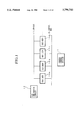
Conventionally, these types of requirements have been handled by increasing the data transfer rates of single buses provided within computers. FIG. 16 is a block diagram illustrating the basic structure of a conventional data transfer system. A central control section 1 uses control signals 6a, 6b and 6c transmitted through a control bus 8 to control a data storage section 2, a data processing section 3 and a network line connection section 4. The data storage section 2 stores real-time media data. In this case, real-time media data denote video and audio data requiring real-time processing. The data processing section 3 prepares real-time media data according to a pre-determined format. The network line connection section 4 interfaces with an ATM network 5 to connect the above system with the ATM network 5.
Signal 7a is real-time media data transferred from the data storage section 2 to the data processing section 3. Similarly, signal 7b is real-time media data transferred from the data processing section 3 through the network line connection section 4 to the ATM network 5. In this case, the ATM (Asynchronous Transfer Mode) network denotes a communication network which performs high-speed processing by dividing all of the communication data, having bit rates of from tens of bps to hundreds of Mbps, into cells (packets) having fixed lengths of 53 bytes (wherein 1 byte=8 bits) and mixing them into transmission routes for transfer in order to perform high-speed packet exchange. Each cell in the ATM network is formed from a 5-byte header (control data portion) and a 48-byte data field. The advantages of ATM networks lie in their high interchangeability and efficiency due to their ability to mix communication traffic of various speeds, including high speeds.
Next, the operation of a data transfer system according to the above structure will be explained for the case wherein a video image signal, as an example of real-time media data, is transferred from the data storage section 2 through the ATM network 5 to a different computer. The central control section 1 sends a control signal 6b via the control bus 8 in order to instruct the data processing section 3 to receive a video signal. In response, the data processing section 3 returns a signal to the central control section 1 indicating whether or not it is capable of receiving the video signal. After confirming that the data processing section 3 is able to receive the video signal, the central control section 1 sends a control signal 6a via the control bus 8 in order to instruct the data storage section 2 to send the video signal to the data processing section 3. Then, the data storage section 2 sends the video signal 7a, which has been pre-stored in the data storage section 2, to the data processing section 3 via the control bus 8. The data processing section 3 receives the video signal 7a sent through the control bus 8 and prepares it to a pre-determined format.
Next, the central control section 1 sends a control signal 6c via the control bus 8 in order to instruct the network line connection section 4 to transfer the video signal 7b formatted from the video signal 7a to the ATM network 5. In response, the network line connection section 4 returns a signal to the central control section 1 indicating whether or not the video signal is capable of being transferred. After confirming that the network line connection section 4 is able to transfer the video signal, the central control section 1 sends the control signal 6b via the control bus 8 in order to instruct the data processing section 3 to send the video signal 7b to the network line connection section 4. Then, the data processing section 3 sends the video signal 7b to the network line connection section 4 via the control bus 8. Finally, the network line connection section 4 transfers the video signal 7b to the ATM network 5.
The conventional data transfer system described above has a weakness in that increases in the amount of data being processed cause control data and real-time media data to compete upon the same bus during continuous data transfer, thereby generating waiting periods between data and making it difficult to achieve real-time transmission of media data. For example, in the conventional data transfer system shown in FIG. 16, if the central control section 1 uses the control signal 6a to instruct the data storage section 2 to send data or the control signal 6b to instruct the data processing section 3 to receive data when a continuous video signal 7b is being transferred to the network line connection section 4 through the ATM network 5, the data signal 6a or 6b will compete with the video signal 7b, as a result of which the transmission of the signal 7b may be interrupted. Such interruptions cause reduced picture quality and image disturbances in the remote computer to which the video signal 7b was being sent through the ATM network 5. As a result, the processing of real-time media data is often interrupted during multi-media communications wherein video signals are processed for communications.
As a solution to this problem, cell buses (transfer type) which use CUBIT (VLSI), developed by Tran Switch Corporation (USA), are known as technology for allowing ATM-type data transfer by buses. Additionally, MVIP (Multivender Integration Protocol) is known as a technology for performing data transfer by providing an STM (Synchronous Transfer Mode) bus independent from the control bus. This standard was introduced in 1990 by Natural Microsystems (NMS), Mitel and five other companies, and GO-MVIP (The Global Organization for MVIP) was inaugurated 1994 as a neutral industrial organization therefor. However, the performance of data transfer by using ATM-type buses along with control buses has conventionally remained unknown.
SUMMARY OF THE INVENTION
The present invention has been developed under the above-described circumstances, and has the object of offering an ATM bus system which is able to handle increases in the amount and types of data for multi-media communications, process data in real-time, and easily manage changes in the size and generation patterns of processing data.
In order to achieve the object, the present invention offers an ATM bus system, for performing data transfers in an asynchronous transfer mode based on fixed-length cell units on a bus for data transmission, which transfers a single cell unit of data when a plurality of bus use requests for performing data transfers on an ATM bus have been generated, said ATM bus system has arbitration means to select a single bus use request from among a plurality of bus use requests simultaneously made by the plurality of bus users, connected to said ATM bus, for performing data transfers by sharing said ATM bus, and designating the bus user which issued said single bus use request; wherein each of said cell units have an expansion header in addition to ATM bus data containing an ATM header; said expansion header comprises bus use request data for said bus users to issue bus use requests to said bus arbitration means, bus use allowance data representing the single bus user designated by said bus arbitration means, and user address data for designating transmission and reception bus users; said bus arbitration means performs an arbitration of the plurality of bus use requests of said bus use request data, and notifies all of the bus users of bus use permission granted to the single bus user by using said bus use allowance data; and said bus users examine said bus use allowance data, whereby only the single bus user which has received bus use permission transfers a cell unit of data within the same cell time as a transfer of said expansion header, and the bus user designated by said user address data receives ATM bus data.
BRIEF DESCRIPTION OF THE DRAWINGS
FIG. 1 is a block diagram showing the structure of an ATM bus system according to the first and second embodiments of the present invention.
FIG. 2 is a diagram showing an example of the structure of a single unit cell on an ATM bus of an ATM bus system according to the first, second and fourth embodiments of the present invention.
FIG. 3 is a diagram showing the operating conditions of an ATM bus system according to the first embodiment of the present invention.
FIG. 4 is a diagram showing the operating conditions of a broadcast in the ATM bus system according to the second embodiment of the present invention.
FIG. 5 is a block diagram showing the structure of an ATM bus system according to the third embodiment of the present invention.
FIG. 6 is a diagram showing the temporal change in the state of use of the ATM bus due to the bus users 10a and 10b in the same ATM bus system.
FIG. 7 is a diagram showing the temporal change in the state of use of the ATM bus due to only the bus users 10b in the same ATM bus system.
FIG. 8 is a diagram showing the temporal change in the state of use of the ATM bus due to the bus users 10c and 10d in the same ATM bus system.
FIG. 9 is a diagram showing an example of the structure of a single unit cell on an ATM bus of the ATM bus system according to the third embodiment of the present invention.
FIG. 10 is a block diagram showing the structure of an ATM bus system according to the fourth embodiment of the present invention.
FIG. 11 is a diagram showing a data transfer operation between post-extension users for the same ATM bus system.
FIG. 12 is a diagram showing the temporal change in the state of use of the main bus and the sub-bus during the same data transfer.
FIG. 13 is a diagram showing a data transfer operation from a post-extension bus user to a pre-extension bus user for the same ATM bus system.
FIG. 14 is a diagram showing an example of the temporal change in the state of use of the main bus and the sub-bus during the same data transfer.
FIG. 15 is a diagram showing a data transfer operation between pre-extension users for the same ATM bus system.
FIG. 16 is a block diagram showing the basic structure of a conventional data transfer system.
PREFERRED EMBODIMENTS OF THE INVENTION
Hereinbelow, the embodiments of the present invention will be explained with reference to the drawings.
Embodiment 1!
FIG. 1 is a block diagram showing the structure of an ATM bus system according to the first embodiment of the present invention. In the drawing, the portions which correspond to parts in FIG. 16 have been given the same reference numerals, and their explanations will be omitted.
In the same drawing, reference numerals 10a˜10d denotes bus users in an ATM bus system. The bus users 10a˜10d are assigned different addresses, so that the bus user is able to be immediately identified by indicating the address. Reference numeral 11 denotes an ATM bus which is a common data transfer route of this ATM bus system. Each bus user 10a˜10d is able to perform a direct data transfer to any partner on this bus via the ATM bus 11. In this case, the transferred data are real-time media data. Reference numeral 12 denotes a bus arbitration circuit. In normal buses, only a single data transfer can be performed at a time. For this reason, the bus arbitration circuit 12 decides which bus user is able to send data at a certain time, thereby arbitrating the competition which occurs because the bus users 10a˜10d share a common data transfer route. The control bus 8 is the transfer route which is used when the central control section 1 transfers control signals to the bus users 10a˜10d, and is not used for the transfer of real-time media data.
On the other hand, this ATM bus system performs data transfer in an ATM transfer mode wherein the data is transferred by a plurality of cells having fixed-length cell units. FIG. 2 shows an example of the data structure of one cell unit on the ATM bus. As shown in the drawing, each cell unit of data is formed from an extension header provided on the leading end and ATM bus data. Furthermore, the extension headers are formed from three types of data fields of bus use request data, bus use allowance data and bus user address data.
In this case, the bus use request data in the extension header is a field containing request data for each bus user to request the bus arbitration circuit 12 to be allowed to use the ATM bus 11. The bus use allowance data is a data field for designating a single bus user which the bus arbitration circuit 12 has selected from among the bus users which have requested bus use according to a procedure to be explained below. The user address data is a data field containing addresses for designating bus users when a bus user sends data to another bus user.
The ATM bus data have 53 bytes and are formed from an ATM header according to the international standard ITU-TS (International Telecommunications Union - Telecommunications Standardization Section) or the ATM forum and an ATM payload which is a data field.
Next, the operation of an ATM bus system according to the above structure will be explained with reference to FIG. 3. In this example, data are transferred from the bus user 10a to the bus user 10d, and data are transferred from the bus user 10b to the bus user 10c. The central control section 1 instructs, by way of the control bus 8, the bus users 10a and 10b to send data. As a result, the bus user 10a sends the sent data SDa to the ATM bus 11 by the cell unit, and the data are received by the bus user 10d by the cell unit as received data RDd. In the same manner, the bus user 10b sends sent data SDb to the ATM bus 11 by the cell unit, and the data are received by the bus user 10c by the cell unit as received data RDc. In the diagram, reference numeral 13 indicates the cell sequence on the ATM bus 11, demonstrating that the cells are sequentially filed on the ATM bus 11 in the order determined by the bus arbitration circuit 12.
The data transfer is performed by continuously repeating the three steps of a bus use request phase, a bus use allowance phase and a data transmission phase as shown in FIG. 2 for each cell time. The phases will be explained below with reference to FIGS. 1 and 2.
(1) Bus Use Request Phase
When there is a request for a data transfer using the bus, each bus user 10a˜10d shares bus use request data to notify the bus arbitration circuit 12 of the request via the ATM bus 11.
(2) Bus Use Allowance Phase
The bus arbitration circuit 12 monitors the bus use request data received from each bus user 10a˜10d for the relevant cell time, and determines which bus users are requesting bus use. As a result of the monitor, a single bus user is chosen from among the plurality of bus users which have requested bus use according to a pre-determined procedure, and is granted permission to send a single cell of data using the ATM bus 11. After a single bus user has been selected in the above manner, data relating to the selected bus user are sent to all of the bus users 10a˜10d via the ATM bus 11 as bus use allowance data.
(3) Data Transmission Phase
Each of the bus users 10a˜10d which have requested bus use examine the bus use allowance data contained in the data received from the bus arbitration circuit 12 in order to determine whether or not it has received permission for a data transfer. As a result of the determination, the bus user which has received permission for the data transfer sends a single cell of data to the ATM bus 11. Simultaneously, each bus user 10a˜10d examines the user address data, and if the address designated in the data matches with the receiving address, then it receives the ATM bus data which follows the user address data. In this way, data is transmitted between the bus users 10a˜10d by fixed-length cell units.
With the present embodiment as explained above, the control signals are transferred by the control bus 8, and the real-time media data are transferred by the ATM bus 11. Therefore, when transferring a continuous video signal by means of the ATM network, the transfer cannot be interrupted even if the central control section 1 gives a send instruction to the bus user 10b via the control bus 8 while transferring the video signal from the bus user 10a to the bus user 10d, since the video signal from the bus user 10a is transferred via the ATM bus 11. Thus, the control signals and the real-time media data are kept completely apart by being transferred through separate buses in order to avoid any mutual influences. For this reason, there is no competition between the two types of signals, and the real-time processing of data such as continuous video signals is achieved.
Furthermore, aside from taking partial charge of the functions of the control bus 8 as a data transfer bus, the ATM bus 11 has the following characteristics due to the use of an ATM format as the data transfer method. The ATM format is a format in which all of the data are divided into fixed-length packets (having 53 bytes+an expansion header in the present case) called cells which are transferred at high speed, whereby it is possible to freely select a transfer rate which does not depend on the amount of communications traffic or the generation patterns. Additionally, the ATM format allows the transfer state to be maintained because the simultaneous, multiple and continuous data do not influence each other. Moreover, the real time media data is transferred directly through the ATM bus 11 in the ATM format, so that the network line connection section does not require a converter in order for the transfer data to be connected to the ATM network, thereby preventing the degradation of the data quality during the network connection.
Embodiment 2!
While multi-media communications require the simultaneous transfer of real-time media data to multiple bus users within a computer, i.e. multiple address communications, conventional multiple address communications are performed by communicating with the multiple bus users to which the data are transferred one at a time. That is, in order to transfer the same data to multiple users according to the conventional methods, the data must be stored and the transfer addresses must be designated for each transfer. However, these types of methods require a lot of time, proportional to the number of bus users on the receiving end in order to completely send all of the data to the bus users.
In order to resolve this problem, there is a method wherein transmission is performed while address data for all of the bus users on the receiving end or address data capable of simultaneously specifying all of the bus users on the receiving end are contained in the header portions of the data cells. However, in these cases, the generation of address data for the transmission routes of the bus users on the sending end and the determination procedure for the reception routes of the bus users on the receiving end (the procedure for determining whether or not the address data within the header indicate the specified address data) become complicated, thus increasing the communications processing time.
The invention according to the second embodiment has been made under these circumstances, and relates to an ATM bus system which can easily perform multiple address communications between a single transmission side bus user and a plurality of reception side bus users on an ATM bus.
While this embodiment will be explained below, the structure of the ATM bus system according to this embodiment is identical to the ATM bus system according to the first embodiment as shown in FIG. 1. Additionally, the data cells according to the present embodiment are similar to the data cells of the first embodiment shown in FIG. 2, except that transmission side user addresses are indicated instead of reception side user addresses as user address data in the expansion headers. Furthermore, the bus arbitration circuit 12 performs arbitration in exactly the same manner.
Next, a multiple address communications operation of an ATM bus system according to the above structure will be explained with reference to FIG. 4. In this example, a multiple address communication is performed from the bus user 10a to the bus users 10b and 10c. First, when a request for transmission of data from the bus user 10a to the bus users 10b and 10c is issued, the bus users 10b and 10c are set with the address of the bus user 10a via the control bus 8. Then, the bus users 10b and 10c respectively store the address in internal memories of the receiving circuits which are not shown in the drawings. Next, the bus user 10a which is on the transmission side stores the data to be sent in the ATM payload portion of the data cell and stores its own (the bus user 10a) address in the user address data portion of the expansion header. Then, the bus user 10a sends the data cell produced in the above manner onto the ATM bus 11 using a transmission route circuit which is not shown.
The bus user 10b on the receiving end constantly monitors the ATM bus 11, so that when a data cell is supplied to the ATM bus 11, it takes in the data cell using a reception route circuit and reads out the transmission side user address data stored in the expansion header portion of the cell. Then, the bus user 10b compares the transmission side user address data with the address stored in its internal memory (the address set via the control bus 8). If the addresses match, then the bus user 10b reads out the data within the ATM payload portion. At that time, a procedure identical to that explained above for the case of the bus user 10b (taking in the data cell, comparing the addresses, and reading out the data in the payload portion) is performed simultaneously and in parallel for the bus user 10c. That is, taking in the data cell, comparing the addresses, and reading out the data in the payload portion are performed separately and in parallel for the bus user 10b and the bus user 10c. A multiple address communication is performed from the bus user 10a to the bus users 10b and 10c according to the above-described procedure.
The bus user 10a stores data by dividing them into a plurality of data cells, then sends the data cells to the ATM bus 11 separately as shown in FIG. 4. Then, the bus users 10b and 10c receive the plurality of data cells sent to the ATM bus 11 separately by the same procedure as with the above-explained receiving method in order to read data from the ATM payload portions of the data cells. In this manner, the multiple address communications method on the ATM bus system according to the present embodiment allows the parallel and simultaneous reception of data by multiple reception side bus users, so that the time required for the data communications procedures is reduced in comparison to conventional methods. Furthermore, the transmission side bus users only need to store their own addresses for the procedure of storing address data in the data cells, and the reception side bus users only need to detect the transmission side user address data received via the control bus 8, thereby simplifying the procedures for the bus users on both the transmission side and the reception side.
Embodiment 3!
When a bus user wishes to transfer data with priority, the bus user adds a priority level indicating the priority of the data transfer when notifying the bus arbitration circuit of a bus use request. Upon receiving the bus request, the bus arbitration circuit begins arbitration from the highest priority level based on the attached priority levels. The invention according to the third embodiment relates to arbitration methods for the bus arbitration circuit for cases in which there are multiple priority levels.
Below, the third embodiment of the present invention will be explained with reference to the diagrams. The operations of the above-mentioned ATM bus system will be explained with reference to FIGS. 5˜8. The structure of the data cells sent and received in this case is shown in FIG. 9.
FIG. 5 is a block diagram showing the composition of the ATM bus system according to the same embodiment. In the drawing, the portions corresponding to parts shown in FIG. 1 are given the same reference numerals, and their explanations will be omitted.
With regard to the bus users 10a˜10d, reference numerals 14a˜14d denote data transfer control circuits which select one from among a plurality of provided priority levels to perform the use request to the ATM bus 11 and the data transfer. Additionally, reference numerals 15a˜15d denote bus controllers having input/output functions on the ATM bus 11.
With regard to the bus arbitration circuit 12, reference numeral 17 denotes a master controller which controls the input and output of the bus controllers 15a˜15d of the bus users 10a˜10d. Reference numerals 18a, 18b, 18c, . . . , 18n denote priority level arbitration circuits, which performs an arbitration of bus use allowance for priority level 1, priority level 2, priority level 3, . . . , priority level n, in the order of highest priority. Furthermore, reference numeral 19 denotes a bus use allowance transmission circuit which collects arbitration results from the priority level arbitration circuits 18a˜18n and notifies all of the bus users 10a˜10d of permission to use the bus via the master controller 17. In this case, the order is such that priority level 1 has the highest priority, followed by priority level 2, priority level 3, . . . , with priority level n having the lowest priority. Additionally, the number of priority level arbitration circuits 18a˜18n provided is equal to the number of priority levels supported by the present system.
In the bus use request phase, when the bus users 10a˜10d have data which needs to be transferred, the data transfer control circuits 14a˜14d select one from among the plurality of priority levels and transmits bus use request data 20 with the selected priority level data 16a˜16d to the master controller 17 via the bus controllers 15a˜15d. Then, the master controller 17 sends the received bus use request data 20a to the priority level 1 arbitration circuit 18a. The diagram shows the situation wherein the bus users 10a and 10b have designated priority level 1 and the bus users 10c and 10d have designated priority level 2.
In the bus use allowance phase, if there are any priority level 1 requests, the priority level 1 arbitration circuit 18a performs an arbitration between the priority level 1 data within the bus use request data 20a. Within the same priority level, the bus users are selected in order and without discrimination. Then, the arbitration result 21a is sent to the bus use allowance transmission circuit 19. On the other hand, if no priority level 1 requests exist, then the bus use request data 20b are sent to the priority level 2 arbitration circuit 18b. If there are any priority level 2 requests, the priority level 2 arbitration circuit 18b sends the arbitration results 21b to the bus use allowance transmission circuit 19. If there are no such requests, the bus use request data 20c are sent to the priority level 3 arbitration circuit 18c. In the same manner, each arbitration circuit performs an arbitration if there are any requests at the corresponding priority level, then transfers the arbitration results to the bus use allowance transmission circuit 19. When the bus use allowance transmission circuit 19 receives one of the arbitration results 21a˜21n, the bus use allowance circuit 19 sends bus use allowance data 22, containing data relating to the bus users selected by the arbitration results, to the master controller 17. Then, the master controller 17 notifies all of the bus users 10a˜10d of the bus use allowance data 22 through the ATM bus 11. In the case shown by example in the diagram, the bus users 10a, 10b, 10c and 10d have respectively designated priority levels 1, 1, 2 and 2, so that the priority level 1 arbitration circuit 18a sends the arbitration result 21a, granting permission to either the bus user 10a or the bus user 10b, to the bus use allowance transmission circuit 19. The bus use allowance data 22 which allow use of the ATM bus 11 are then sent to the bus users 10a ˜10d.
In the data transmission phase, the bus users 10a˜10d which have requested bus use examine the bus use allowance data contained in the data received from the bus arbitration circuit 12 in order to determine whether or not they have received permission for a data transfer. If the determination reveals that transfer permission has been granted, then one cell of data is sent from the relevant bus user to the ATM bus 11. In this example, the bus users 10a and 10b reciprocally transfer data. This situation is shown in FIG. 6.
FIG. 6 illustrates the flow of data on the ATM bus when the bus users have the priority levels shown in FIG. 5. Since the situation is such that:
Bus user 10a has priority level 1
Bus user 10b has priority level 1
Bus user 10c has priority level 2
Bus user 10d has priority level 2 the bus users 10a and 10b perform data transfers in reciprocating fashion.
FIG. 7 illustrates the situation of FIG. 6 wherein the bus user 10a is no longer requesting use, such that:
Bus user 10a is not requesting use
Bus user 10b has priority level 1
Bus user 10c has priority level 2
Bus user 10d has priority level 2 and only the bus user 10b is performing a data transfer.
FIG. 8 illustrates the situation of FIG. 7 wherein the bus user 10b is no longer requesting use, such that:
Bus user 10a is no longer requesting use
Bus user 10b is no longer requesting use
Bus user 10c has priority level 2
Bus user 10d has priority level 2 and the bus is being used by the bus users 10c and 10d in reciprocating fashion.
As explained above, the invention according to the present embodiment is system wherein a single ATM bus is shared by a plurality of bus users, the bus arbitration circuit is notified of priority level data which are contained within the bus use request data of the bus users, and the bus arbitration circuit selects the bus use requests from the bus users having the highest priority to grant the right to use the bus. As a result, the present invention allows the bus users having data of higher priority to be given priority for using the ATM bus for data transfer.
Embodiment 4!
When expanding the ATM bus 11 shown in FIG. 1 in order to increase the data transfer capacity of the ATM bus 11, there is a method wherein the bit width of the ATM bus 11 is expanded while leaving the control bus 8 and the bus cycle formed from the bus use request phase, the bus use allowance phase and the data communication phase identical before and after the expansion, so that the amount of data transferred for each transfer is expanded. However, in this method, while bus users corresponding to the new bit width can be connected to the expanded ATM bus 11, bus users corresponding to the bit width of the ATM bus 11 prior to expansion cannot be connected. Furthermore, the master controller of the bus arbitration circuit 12 must be changed so as to correspond to the bit width of the ATM bus 11 after expansion.
The invention according to the fourth embodiment was made under consideration of these problems, and relates to an ATM bus system which allows bus users corresponding to the bit width of the ATM bus prior to expansion to connect to the ATM bus after expansion.
The fourth embodiment of the present invention will be explained below with reference to the drawings. FIG. 10 is a block diagram showing the structure of an ATM bus system according to the fourth embodiment. In the diagram, the portions which correspond to parts shown in FIG. 1 have been given the same reference numerals, and their explanation will be omitted. The central control section 1 and the control bus 8 have been omitted from the drawing.
The ATM bus system shown in the diagram has two ATM buses, identical to the pre-expansion ATM bus 11 and disposed in parallel, referred to as the main bus 11A and the sub-bus 11B. Here, the main bus 11A is the first ATM bus used during data transfer, while the sub-bus 11B is an ATM bus which is used when the data transfer in the main bus 11A is congested. Bus controllers 15c and 15d of the bus users 10c and 10d corresponding to the pre-expansion ATM bus are connected to the main bus 11A. Reference numeral 10e denotes a bus user provided to replace the bus user 10a, having two bus controllers 15eA and 15eB with the same capabilities as the bus controllers 15c and 15d of the bus users 10e and 10d. One of the bus controllers 15eA is connected to the main bus 11A, while the other bus controller 15eB is connected to the sub-bus 11B. Additionally, reference numeral 24e refers to a bus use condition detection circuit, which monitors the state of use of the main bus 11A by use condition data 25e from the bus controller 15eA. Furthermore, reference numeral 26e denotes a bus selection circuit which switches between buses by the minimum units of data transfer according to bus congestion data 27e which is transferred when the bus use condition detection circuit 24e detects congestion in the main bus 11A by means of the use condition data 25e. At this time, the bus selection circuit 26e outputs a bus controller control signal 28e, for selecting the bus to be used, to the bus controllers 15eA and 15eB.
Reference numeral 10f refers to a bus user provided to replace the bus user 10b, having the same structure as the bus user 10e. The bus controller 15fA of this bus user 10f is connected to the main bus 11A, while the bus controller 15fB is connected to the sub-bus 11B. Reference numeral 12a denotes a bus arbitration circuit which performs an arbitration of the bus use of both the main bus 11A and the sub-bus 11B, and synchronizes both bus cycles. In this bus arbitration circuit 12a, 17A and 17B are master controllers which have the same functions as the master controllers provided in the bus arbitration circuit 12 before expansion and respectively control the bus controllers connected to the main bus 11A and the sub-bus 11B. Additionally, reference numeral 29 denotes a synchronous control section which synchronizes the bus cycles of the main bus 11A and the sub-bus 11B according to the same synchronization signal 30.
Next, the operation of an ATM bus system according to the above-described structure will be explained. The bus users 10c and 10d are connected to only the main bus 11A, and operate in exactly the same manner as prior to expansion using the main bus 11A. The bus users 10e and 10f are connected to both the main bus 11A and the sub-bus 11B. When transferring a single unit of data, the buses are not used simultaneously; the main bus 11A is first used. Then, the sub-bus 11B is only used when the bus condition detection circuits 24e and 24f have determined that the main bus 11A is congested. The data transfer between these bus users is performed based on a bus use request phase, a bus use allowance phase and a data communication phase as with the first embodiment.
An example of the operation of the ATM bus system according to the above structure will be explained below. First, data transfer between the bus users 10e and 10f corresponding to bus expansion will be explained with reference to FIG. 11. In this case, data is transferred from the bus user 10e to the bus user 10f. The bus user 10e performs a data transfer 31A to the bus user 10f using the main bus 11A. Then, if the main bus 11A is being used by another bus user, the bus use condition detection circuit 24e of the bus user 10e determines that the main bus 11A is congested based on the use condition data 25e and sends bus congestion data 27e to the bus selection circuit 26e.
Next, the bus selection circuit 26e receives the bus congestion data 27e and instructs the bus controller 15eA connected to the main bus 11A to stop the data transfer. At the same time, the bus controller 15eB connected to the sub-bus 11B is instructed to transfer data. As a result, the data transfer 31A being performed by the main bus 11A is switched to a data transfer 31B by the sub-bus 11B. At that time, the bus user 10f is receiving data from the main bus 11A, but then begins to receive data from the sub-bus 11B by means of the switching of the transfer bus of the bus user 10e. In this case, while the bus user 10f simultaneously receives the data on the main bus 11A and the sub-bus 11B, the procedure is performed by discriminating the data to be received according to addresses recorded in the user address data.
Then, when the other bus user stops using the main bus 11A and the main bus 11A goes into a state of disuse, the bus use condition detection circuit 24e determines that the congestion of the main bus 11A has been resolved. As a result, the bus selection circuit 26e instructs the bus controller 15eB to stop transferring data and instructs the bus controller 15eA to transfer data, by means of a bus controller control signal 28e. Thus, the data transfer 31B on the sub-bus 11B is switched to a data transfer 31A on the main bus 11A, and the bus user 10f starts receiving data from the main bus 11A.
FIG. 12 is a diagram showing the temporal changes in the state of bus use of the main bus 11A and the sub-bus 11B. In this example, if the main bus 11A becomes congested while the bus user 10e is using the main bus 11A to transfer data to the bus user 10f, the bus user 10e uses the sub-bus 11B, then starts using the main bus 11A again after the congestion of the main bus 11A is resolved. In the diagram, each frame indicates a bus cycle, and the frame 32a marked "10e using" indicates the bus cycle which the bus user 10e used for data transfer. Additionally, the frame 32b indicates the bus cycle that another bus user used for data transfer, and the frame 32c indicates an unused bus cycle.
Next, a data transfer between a bus user 10c corresponding to pre-expansion and a bus user 10e corresponding to expansion will be explained with reference to FIG. 13. In this case, the bus user 10e is transferring data to the bus user 10c. First, the bus user 10e performs a data transfer 33A to the bus user 10 using the main bus 11A, then another bus user begins to use the main bus 11A. However, at this time the bus user 10e does not perform the same switching operation, determining that the main bus 11A is congested, from a data transfer 33A on the main bus 11A to a data transfer on the sub-bus 11B. That is, the bus user 10c cannot receive data from the sub-bus 11B, so the bus user 10e cannot perform a data transfer when the main bus 11A is congested. In this case, the bus user 10e can be kept from performing a switching operation to a sub-bus 11B while the main bus 11A are congested by pre-recording the addresses of the bus users 10c and 10d corresponding to pre-expansion through the control bus 8. Then, when the main bus 11A goes into a state of disuse and the bus use condition detection circuit 24e determines that the congestion of the main bus 11A has been resolved, the data transfer 33A to the bus user 10c using the main bus 11A is restarted.
FIG. 14 is a diagram showing the temporal changes in the bus use conditions of the main bus 11A and the sub-bus 11B for this case. The frames 32a, 32b and 32c are identical to the bus cycles of FIG. 12. In the same diagram, when the bus user 10e uses the main bus 11A to transfer data to the bus user 10c, the data transfer is stopped if the main bus 11A becomes congested, and the data transfer is restarted when the congestion is resolved.
Finally, a data transfer between the bus users 10c and 10d which correspond to pre-expansion will be explained with reference to FIG. 15. The diagram shows the case of a data transfer 34A from the bus user 10c to the bus user 10d. In this case, the data transfer is performed only through the main bus 11A since both the bus users 10c and 10d are connected only to the main bus 11A. That is, the data transfer is performed in exactly the same manner as prior to expansion.
Thus, the invention according to the fourth embodiment has two ATM buses arranged in parallel and having the same bit width as prior to expansion as shown in FIG. 10. Bus users corresponding to pre-expansion are able to be connected to the main bus in order to use only the main bus. Bus users which correspond to bus expansion and are connected to both of the buses use the main bus when transferring data to bus users corresponding to pre-expansion, and normally use the main bus when transferring data to bus users corresponding to bus expansion, and use the sub-bus only when the main bus is congested. The determination of whether the main bus is congested can be performed by monitoring the bus use request data (see FIG. 2) on the main bus. Furthermore, transmission side bus users corresponding to bus expansion do not simultaneously use both buses in the same bus cycle in order to maintain the order of data arrival at the receiving side bus users. Additionally, the receiving side bus users are capable of receiving data simultaneously from separate bus users within the same bus cycle. Then, the bus arbitration circuit of the present invention has a synchronization control section which completely synchronizes the bus cycles so that there is no need to re-adjust the timing within the bus users to the switched bus cycle each time the bus users switch buses.
According to the above-described structure, the data transfer capacity of the ATM buses is doubled by expanding the buses by arranging two pre-expansion ATM buses in parallel. Additionally, it is possible to use both bus users corresponding to bus expansion and bus users corresponding to pre-expansion since both the main bus and the sub-bus after expansion have bit widths equal to that of the pre-expansion ATM bus. Furthermore, the bus users corresponding to pre-expansion can perform data transfers in the same manner as prior to expansion by connecting the bus users corresponding to pre-expansion to the main bus.
While four possible embodiments of the present invention have been explained above with reference to the drawings, the detailed structure need not be restricted to these embodiments, so that any modifications which do not counter the gist of the present invention would still fall within the scope of the invention.

Claims (12)

We claim:
1. An ATM bus system for transferring data in an asynchronous transfer mode using fixed-length cell units, the ATM bus transferring a single cell unit of data when a plurality of bus use requests for transferring data on an ATM bus are generated, said ATM bus system comprising:
a plurality of bus users connected to said ATM bus and sharing said ATM bus to transfer data; and
bus arbitration means for selecting a single bus use request from among a plurality of bus use requests simultaneously sent from said bus users, and for designating the bus user that issued said selected bus use request; wherein
each of said cell units include an expansion header in addition to an ATM bus header, said expansion header having bus use request data for indicating which said bus users issue bus use requests to said bus arbitration means, user address data for indicating bus users that have sent or are to receive data, and bus allowance data for indicating the designated bus user;
said bus arbitration means performing an arbitration of the plurality of bus use requests based on said bus use request data and notifying all of the bus users of bus use permission granted to the selected bus user through said bus use allowance data; and wherein
said bus users examine said bus use allowance data so that only the bus user designated by the allowance data transfers a cell unit of data within the same cell time as a transfer of said expansion header, and each bus user decides whether or not to receive ATM bus data in the transferred cell unit of data based on the user address data in the same cell unit of data.
2. An ATM bus system according to claim 1, further comprising:
central control means for controlling procedures and data transfers performed by said bus users; and
a control bus for transferring control data from said central control means to said bus users in order to control said bus users.
3. An ATM bus system according to claim 2, having a plurality of priority levels indicating priority levels of said data transfers; wherein
each of said bus users selects a single priority level from among said plurality of priority levels and adds said selected priority level to said bus use request data; and
said arbitration means performs a multi-level priority bus arbitration wherein bus use permission is granted from among the bus use requests in a single priority level, of which there are no bus use requests of a higher priority level, by ignoring the bus use requests of priority levels lower than said single priority level.
4. An ATM bus system according to claim 1, having a plurality of priority levels indicating priority levels of said data transfers, wherein
each of said bus users selects a single priority level from among said plurality of priority levels and adds said selected priority level to said bus use request data; and
said arbitration means performs a multi-level priority bus arbitration wherein bus use permission is granted from among the bus use requests in a single priority level, of which there are no bus use requests of a higher priority level, by ignoring the bus use requests of priority levels lower than said single priority level.
5. An ATM bus system for transferring data in an asynchronous transfer mode using fixed-length cell units, the ATM bus transferring a single cell unit of data when a plurality of bus use requests for transferring data on an ATM bus are generated, said ATM bus system comprising:
a plurality of bus users connected to said ATM bus and sharing said ATM bus to transfer data;
bus arbitration means for selecting a single bus use request from among a plurality of bus use requests simultaneously sent from said bus users, and for designating the bus user that issued said selected bus use request;
central control means for controlling procedures and data transfers performed by said bus users; and
a control bus for transferring control data from said central control means to said bus users in order to control said bus users; wherein
each of said cell units include an expansion header in addition to an ATM bus header, said expansion header having bus use request data for indicating which said bus users issue bus use requests to said bus arbitration means, user address data for indicating bus users that have sent or are to receive data, and bus allowance data for indicating the designated bus user;
said bus arbitration means performing an arbitration of the plurality of bus use requests based on said bus use request data and notifying all of the bus users of bus use permission granted to the selected bus user through said bus use allowance data;
said bus users examine said bus use allowance data so that only the bus user designated by the allowance data transfers a cell unit of data within the same cell time as a transfer of said expansion header, and each bus user decides whether or not to receive ATM bus data in the transferred cell unit of data based on the user address data in the same cell unit of data;
the addresses of the bus users which transmit data are preset through the control bus with respect to all bus users which receive data;
each of the bus users which transmit data applies its own bus user address to the expansion header of a cell unit and sends said cell unit to the ATM bus through a transmission circuit within said bus user; and
each of the bus users which receive data work in parallel to compare the transmitting user address preset through said control bus with the address in the cell unit on the ATM bus, and receive said cell unit when the addresses match.
6. An ATM bus system according to claim 5, having a plurality of priority levels indicating priority levels of said data transfers; wherein
each of said bus users selects a single priority level from among said plurality of priority levels and adds said selected priority level to said bus use request data; and
said arbitration means performs a multi-level priority bus arbitration wherein bus use permission is granted from among the bus use requests of priority level, of which there are no bus use requests of a higher priority level, by ignoring the bus use requests of priority levels lower than said single priority level.
7. An ATM bus system according to claim 6, wherein
said ATM bus including a main bus and an identical sub-bus arranged in parallel;
said bus arbitration means includes two master controllers separately arbitrating said bus use requests from said bus users during each data transfer on said main bus and said sub-bus and a synchronization control section for synchronizing bus cycles of said main bus and said sub-bus;
said bus users being connected to said main bus and sharing said main bus and said sub-bus;
each of said bus users further comprises:
bus controllers, connected respectively to said main bus and said sub-bus, which respectively output said bus use requests to said master controllers when data is to be transferred, and respectively performing data transfer when bus use permission has been granted by said master controllers;
bus use condition detection means for determining a condition of use of the ATM bus; and
bus selection means for switching transfer of each cell unit of data between said main bus and said sub-bus based on bus congestion data from said bus use condition detection means; and wherein
said bus users normally use said main bus for transferring each cell unit of data, and use said sub-bus only when said bus use condition detection means determines that the main bus is congested.
8. An ATM bus system according to claim 5, wherein
the ATM bus includes a main bus and an identical sub-bus arranged in parallel;
said bus arbitration means includes two master controllers separately arbitrating said bus use requests from said bus users during each data transfer on said main bus and said sub-bus, and a synchronization control section for synchronizing bus cycles of said main bus and said sub-bus;
said bus users being connected to said main bus and sharing said main bus and said sub-bus;
each of said bus users further comprising:
bus controllers, connected respectively to said main bus and said sub-bus, which respectively output said bus use requests to said master controllers when data is to be transferred, and respectively performing data transfer when bus use permission has been granted by said master controllers;
bus use condition detection means for determining a condition of use of the ATM bus; and
bus selection means for switching transfer of each cell unit of data between said main bus and said sub-bus based on bus congestion data from said bus use condition detection means; and wherein
said bus users normally use said main bus for transferring each cell unit of data, and use said sub-bus only when said bus use condition detection means determines that the main bus is congested.
9. An ATM bus system for transferring data in an asynchronous transfer mode using fixed-length cell units, the ATM bus transferring a single cell unit of data when a plurality of bus use requests for transferring data on an ATM bus are generated, said ATM bus system comprising:
a plurality of bus users connected to said ATM bus and sharing said ATM bus to transfer data, the ATM bus including a main bus and an identical sub-bus arranged in parallel, said bus users being connected to said main bus and sharing said main bus and said sub-bus; and
bus arbitration means for selecting a single bus use request from among a plurality of bus use requests simultaneously sent from said bus users, and for designating the bus user that issued said selected bus use request, the bus arbitration means including two master controllers separately arbitrating said bus use requests from said bus users during each data transfer on said main bus and said sub-bus, and a synchronization control section for synchronizing bus cycles of said main bus and said sub-bus;
each of said bus users further comprising:
bus controllers, connected respectively to said main bus and said sub-bus, which respectively output said bus use requests to said master controllers when data is to be transferred, and respectively performing data transfer when bus use permission has been granted by said master controllers;
bus use condition detection means for determining a condition of use of the ATM bus; and
bus selection means for switching transfer of each cell unit of data between said main bus and said sub-bus based on bus congestion data from said bus use condition detection means; and wherein
said bus users normally use said main bus for transferring each cell unit of data, and use said sub-bus only when said bus use condition detection means determines that the main bus is congested; and further wherein
each of said cell units include an expansion header in addition to an ATM bus header, said expansion header having bus use request data for indicating which said bus users issue bus use requests to said bus arbitration means, user address data for indicating bus users that have sent or are to receive data, and bus allowance data for indicating the designated bus user;
said bus arbitration means performing an arbitration of the plurality of bus use requests based on said bus use request data and notifying all of the bus users of bus use permission granted to the selected bus user through said bus use allowance data; and wherein
said bus users examine said bus use allowance data so that only the bus user designated by the allowance data transfers a cell unit of data within the same cell time as a transfer of said expansion header, and each bus user decides whether or not to receive ATM bus data in the transferred cell unit of data based on the user address data in the same cell unit of data.
10. An ATM bus system for transferring data in an asynchronous transfer mode using fixed-length cell units, the ATM bus transferring a single cell unit of data when a plurality of bus use requests for transferring data on an ATM bus are generated, said ATM bus system comprising:
a plurality of bus users connected to said ATM bus and sharing said ATM bus to transfer data, the ATM bus including a main bus and an identical sub-bus arranged in parallel, said bus users being connected to said main bus and sharing said main bus and said sub-bus;
bus arbitration means for selecting a single bus use request from among a plurality of bus use requests simultaneously sent from said bus users, and for designating the bus user that issued said selected bus use request, the bus arbitration means including two master controllers separately arbitrating said bus use requests from said bus users during each data transfer on said main bus and said sub-bus, and a synchronization control section for synchronizing bus cycles of said main bus and said sub-bus;
central control means for controlling procedures and data transfers performed by said bus, users; and
a control bus for transferring control data from said central control means to said bus users in order to control said bus users;
each of said bus users further comprising:
bus controllers, connected respectively to said main bus and said sub-bus, which respectively output said bus use requests to said master controllers when data is to be transferred, and respectively performing data transfer when bus use permission has been granted by said master controllers;
bus use condition detection means for determining a condition of use of the ATM bus; and
bus selection means for switching transfer of each cell unit of data between said main bus and said sub-bus based on bus congestion data from said bus use condition detection means; and wherein
said bus users normally use said main bus for transferring each cell unit of data, and use said sub-bus only when said bus use condition detection means determines that the main bus is congested; and further wherein
each of said cell units include an expansion header in addition to an ATM bus header, said expansion header having bus use request data for indicating which said bus users issue bus use requests to said bus arbitration means, user address data for indicating bus users that have sent or are to receive data, and bus allowance data for indicating the designated bus user;
said bus arbitration means performing an arbitration of the plurality of bus use requests based on said bus use request data and notifying all of the bus users of bus use permission granted to the selected bus user through said bus use allowance data; and wherein
said bus users examine said bus use allowance data so that only the bus user designated by the allowance data transfers a cell unit of data within the same cell time as a transfer of said expansion header, and each bus user decides whether or not to receive ATM bus data in the transferred cell unit of data based on the user address data in the same cell unit of data.
11. An ATM bus system for transferring data in an asynchronous transfer mode using fixed-length cell units, the ATM bus transferring a single cell unit of data when a plurality of bus use requests for transferring data on an ATM bus are generated, said ATM bus system comprising:
a plurality of bus users connected to said ATM bus and sharing said ATM bus to transfer data, the ATM bus including a main bus and an identical sub-bus arranged in parallel, said bus users being connected to said main bus and sharing said main bus and said sub-bus, and having a plurality of priority levels indicating priority levels of said data transfers, each of said bus users selecting a single priority level from among said plurality of priority levels and adding said selected priority level to said bus use request data; and
bus arbitration means for selecting a single bus use request from among a plurality of bus use requests simultaneously sent from said bus users, and for designating the bus user that issued said selected bus use request, the bus arbitration means including two master controllers separately arbitrating said bus use requests from said bus users during each data transfer on said main bus and said sub-bus, and a synchronization control section for synchronizing bus cycles of said main bus and said sub-bus, said arbitration means performing a multi-level priority bus arbitration wherein bus use permission is granted from among the bus use requests in a single priority level, of which there are no bus use requests of a higher priority level, by ignoring the bus use requests of priority levels lower than said single priority level; wherein
each of said bus users further comprising:
bus controllers, connected respectively to said main bus and said sub-bus, which respectively output said bus use requests to said master controllers when data is to be transferred, and respectively performing data transfer when bus use permission has been granted by said master controllers;
bus use condition detection means for determining a condition of use of the ATM bus; and
bus selection means for switching transfer of each cell unit of data between said main bus and said sub-bus based on bus congestion data from said bus use condition detection means; wherein
said bus users normally use said main bus for transferring each cell unit of data, and use said sub-bus only when said bus use condition detection means determines that the main bus is congested; and further wherein
each of said cell units include an expansion header in addition to an ATM bus header, said expansion header having bus use request data for indicating which said bus users issue bus use requests to said bus arbitration means, user address data for indicating bus users that have sent or are to receive data, and bus allowance data for indicating the designated bus user;
said bus arbitration means performing an arbitration of the plurality of bus use requests based on said bus use request data and notifying all of the bus users of bus use permission granted to the selected bus user through said bus use allowance data; and wherein
said bus users examine said bus use allowance data so that only the bus user designated by the allowance data transfers a cell unit of data within the same cell time as a transfer of said expansion header, and each bus user decides whether or not to receive ATM bus data in the transferred cell unit of data based on the user address data in the same cell unit of data.
12. An ATM bus system for transferring data in an asynchronous transfer mode using fixed-length cell units, the ATM bus transferring a single cell unit of data when a plurality of bus use requests for transferring data on an ATM bus are generated, said ATM bus system comprising:
a plurality of bus users connected to said ATM bus and sharing said ATM bus to transfer data, the ATM bus including a main bus and an identical sub-bus arranged in parallel, said bus users being connected to said main bus and sharing said main bus and said sub-bus; and having a plurality of priority levels indicating priority levels of said data transfers, each of said bus users selecting a single priority level from among said plurality of priority levels and adding said selected priority level to said bus use request data; and
bus arbitration means for selecting a single bus use request from among a plurality of bus use requests simultaneously sent from said bus users, and for designating the bus user that issued said selected bus use request, the bus arbitration means including two master controllers separately arbitrating said bus use requests from said bus users during each data transfer on said main bus and said sub-bus, and a synchronization control section for synchronizing bus cycles of said main bus and said sub-bus, said arbitration means performing a multi-level priority bus arbitration wherein bus use permission is granted from among the bus use requests in a single priority level, of which there are no bus use requests of a higher priority level, by ignoring the bus use requests of priority levels lower than said single priority level;
central control means for controlling procedures and data transfers performed by said bus, users; and
a control bus for transferring control data from said central control means to said bus users in order to control said bus users;
each of said bus users further comprises:
bus controllers, connected respectively to said main bus and said sub-bus, which respectively output said bus use requests to said master controllers when data is to be transferred, and respectively performing data transfer when bus use permission has been granted by said master controllers;
bus use condition detection means for determining a condition of use of the ATM bus; and
bus selection means for switching transfer of each cell unit of data between said main bus and said sub-bus based on bus congestion data from said bus use condition detection means; and wherein
said bus users normally use said main bus for transferring each cell unit of data, and use said sub-bus only when said bus use condition detection means determines that the main bus is congested; and further wherein
each of said cell units include an expansion header in addition to an ATM bus header, said expansion header having bus use request data for indicating which said bus users issue bus use requests to said bus arbitration means, user address data for indicating bus users that have sent or are to receive data, and bus allowance data for indicating the designated bus user;
said bus arbitration means performing an arbitration of the plurality of bus use requests based on said bus use request data and notifying all of the bus users of bus use permission granted to the selected bus user through said bus use allowance data; and wherein
said bus users examine said bus use allowance data so that only the bus user designated by the allowance data transfers a cell unit of data within the same cell time as a transfer of said expansion header, and each bus user decides whether or not to receive ATM bus data in the transferred cell unit of data based on the user address data in the same cell unit of data.
US08/611,048 1995-03-09 1996-03-05 ATM bus system Expired - Lifetime US5796741A (en)

Priority Applications (3)

Application Number Priority Date Filing Date Title
US08/611,048 US5796741A (en) 1995-03-09 1996-03-05 ATM bus system
CA002171366A CA2171366C (en) 1995-03-09 1996-03-08 Atm bus system
JP08053527A JP3127950B2 (en) 1995-03-09 1996-03-11 ATM bus system

Applications Claiming Priority (4)

Application Number Priority Date Filing Date Title
JP5022695 1995-03-09
JP13703395 1995-06-02
JP13703495 1995-06-02
US08/611,048 US5796741A (en) 1995-03-09 1996-03-05 ATM bus system

Publications (1)

Publication Number Publication Date
US5796741A true US5796741A (en) 1998-08-18

Family

ID=27462461

Family Applications (1)

Application Number Title Priority Date Filing Date
US08/611,048 Expired - Lifetime US5796741A (en) 1995-03-09 1996-03-05 ATM bus system

Country Status (2)

Country Link
US (1) US5796741A (en)
CA (1) CA2171366C (en)

Cited By (67)

* Cited by examiner, † Cited by third party
Publication number Priority date Publication date Assignee Title
US20020058502A1 (en) * 2000-11-13 2002-05-16 Peter Stanforth Ad hoc peer-to-peer mobile radio access system interfaced to the PSTN and cellular networks
US6404756B1 (en) * 1999-11-03 2002-06-11 Itt Manufacturing Enterprises, Inc. Methods and apparatus for coordinating channel access to shared parallel data channels
US20020085526A1 (en) * 2000-11-08 2002-07-04 Belcea John M. Time division protocol for an ad-hoc, peer-to-peer radio network having coordinating channel access to shared parallel data channels with separate reservation channel
US20020191573A1 (en) * 2001-06-14 2002-12-19 Whitehill Eric A. Embedded routing algorithms under the internet protocol routing layer of a software architecture protocol stack in a mobile Ad-Hoc network
US20030035437A1 (en) * 2001-08-15 2003-02-20 Masood Garahi Movable access points and repeaters for minimizing coverage and capacity constraints in a wireless communications network and a method for using the same
US20030040316A1 (en) * 2001-03-22 2003-02-27 Peter Stanforth Prioritized-routing for an ad-hoc, peer-to-peer, mobile radio access system based on battery-power levels and type of service
US20030043790A1 (en) * 2001-09-06 2003-03-06 Philip Gutierrez Multi-master bus architecture for system -on-chip designs
US20030058886A1 (en) * 2001-09-25 2003-03-27 Stanforth Peter J. System and method employing algorithms and protocols for optimizing carrier sense multiple access (CSMA) protocols in wireless networks
US20030060202A1 (en) * 2001-08-28 2003-03-27 Roberts Robin U. System and method for enabling a radio node to selectably function as a router in a wireless communications network
US20030076837A1 (en) * 2001-10-23 2003-04-24 Whitehill Eric A. System and method for providing a congestion optimized address resolution protocol for wireless Ad-Hoc Networks
US20030091011A1 (en) * 2001-08-15 2003-05-15 Roberts Robin U. System and method for performing soft handoff in a wireless data network
US6580981B1 (en) 2002-04-16 2003-06-17 Meshnetworks, Inc. System and method for providing wireless telematics store and forward messaging for peer-to-peer and peer-to-peer-to-infrastructure a communication network
US6617990B1 (en) 2002-03-06 2003-09-09 Meshnetworks Digital-to-analog converter using pseudo-random sequences and a method for using the same
US20030214921A1 (en) * 2002-05-16 2003-11-20 Alapuranen Pertti O. System and method for performing multiple network routing and provisioning in overlapping wireless deployments
US20030227895A1 (en) * 2002-06-05 2003-12-11 Strutt Guenael T. System and method for improving the accuracy of time of arrival measurements in a wireless ad-hoc communications network
US20030228875A1 (en) * 2002-06-05 2003-12-11 Alapuranen Pertti O. MAC protocol with duty-cycle limitation for portable devices in a wireless Ad-Hoc communication network and a method for using the same
US20030227934A1 (en) * 2002-06-11 2003-12-11 White Eric D. System and method for multicast media access using broadcast transmissions with multiple acknowledgements in an Ad-Hoc communications network
US6674790B1 (en) 2002-01-24 2004-01-06 Meshnetworks, Inc. System and method employing concatenated spreading sequences to provide data modulated spread signals having increased data rates with extended multi-path delay spread
US20040005902A1 (en) * 2002-07-05 2004-01-08 Belcea John M. System and method for correcting the clock drift and maintaining the synchronization of low quality clocks in wireless networks
US6687259B2 (en) 2002-06-05 2004-02-03 Meshnetworks, Inc. ARQ MAC for ad-hoc communication networks and a method for using the same
US20040028017A1 (en) * 2002-07-29 2004-02-12 Whitehill Eric A. System and method for determining physical location of a node in a wireless network during an authentication check of the node
US20040042481A1 (en) * 2002-08-28 2004-03-04 Sreenath Kurupati Facilitating arbitration via information associated with groups of requesters
US6728545B1 (en) 2001-11-16 2004-04-27 Meshnetworks, Inc. System and method for computing the location of a mobile terminal in a wireless communications network
US6728232B2 (en) 2002-03-15 2004-04-27 Meshnetworks, Inc. System and method for auto-configuration and discovery of IP to MAC address mapping and gateway presence in wireless peer-to-peer ad-hoc routing networks
US20040081166A1 (en) * 2002-05-01 2004-04-29 Stanforth Peter J. System and method for using an ad-hoc routing algorithm based on activity detection in an ad-hoc network
US20040082341A1 (en) * 2002-05-17 2004-04-29 Stanforth Peter J. System and method for determining relative positioning in ad-hoc networks
US20040086269A1 (en) * 2002-11-06 2004-05-06 Mediostream, Inc Method and system for writing video presentation and navigation information direct to optical disc
US6744766B2 (en) 2002-06-05 2004-06-01 Meshnetworks, Inc. Hybrid ARQ for a wireless Ad-Hoc network and a method for using the same
US6754188B1 (en) 2001-09-28 2004-06-22 Meshnetworks, Inc. System and method for enabling a node in an ad-hoc packet-switched wireless communications network to route packets based on packet content
US20040143842A1 (en) * 2003-01-13 2004-07-22 Avinash Joshi System and method for achieving continuous connectivity to an access point or gateway in a wireless network following an on-demand routing protocol, and to perform smooth handoff of mobile terminals between fixed terminals in the network
US6768730B1 (en) 2001-10-11 2004-07-27 Meshnetworks, Inc. System and method for efficiently performing two-way ranging to determine the location of a wireless node in a communications network
US6771666B2 (en) 2002-03-15 2004-08-03 Meshnetworks, Inc. System and method for trans-medium address resolution on an ad-hoc network with at least one highly disconnected medium having multiple access points to other media
US20040179667A1 (en) * 2003-03-14 2004-09-16 Meshnetworks, Inc. System and method for analyzing the precision of geo-location services in a wireless network terminal
US20040246986A1 (en) * 2003-06-06 2004-12-09 Meshnetworks, Inc. MAC protocol for accurately computing the position of wireless devices inside buildings
US20040246935A1 (en) * 2003-06-06 2004-12-09 Meshnetworks, Inc. System and method for characterizing the quality of a link in a wireless network
US20040246975A1 (en) * 2003-06-06 2004-12-09 Meshnetworks, Inc. System and method to improve the overall performance of a wireless communication network
US20040252643A1 (en) * 2003-06-05 2004-12-16 Meshnetworks, Inc. System and method to improve the network performance of a wireless communications network by finding an optimal route between a source and a destination
US20040252630A1 (en) * 2003-06-05 2004-12-16 Meshnetworks, Inc. System and method for determining synchronization point in OFDM modems for accurate time of flight measurement
US20040258040A1 (en) * 2003-06-05 2004-12-23 Meshnetworks, Inc. System and method to maximize channel utilization in a multi-channel wireless communiction network
US20040259571A1 (en) * 2003-06-05 2004-12-23 Meshnetworks, Inc. System and method for determining location of a device in a wireless communication network
US6873839B2 (en) 2000-11-13 2005-03-29 Meshnetworks, Inc. Prioritized-routing for an ad-hoc, peer-to-peer, mobile radio access system
US6904021B2 (en) 2002-03-15 2005-06-07 Meshnetworks, Inc. System and method for providing adaptive control of transmit power and data rate in an ad-hoc communication network
US20050186966A1 (en) * 2003-03-13 2005-08-25 Meshnetworks, Inc. Real-time system and method for improving the accuracy of the computed location of mobile subscribers in a wireless ad-hoc network using a low speed central processing unit
US6970444B2 (en) 2002-05-13 2005-11-29 Meshnetworks, Inc. System and method for self propagating information in ad-hoc peer-to-peer networks
US6982982B1 (en) 2001-10-23 2006-01-03 Meshnetworks, Inc. System and method for providing a congestion optimized address resolution protocol for wireless ad-hoc networks
US6987795B1 (en) 2002-04-08 2006-01-17 Meshnetworks, Inc. System and method for selecting spreading codes based on multipath delay profile estimation for wireless transceivers in a communication network
US20060077938A1 (en) * 2004-10-07 2006-04-13 Meshnetworks, Inc. System and method for creating a spectrum agile wireless multi-hopping network
US7046962B1 (en) 2002-07-18 2006-05-16 Meshnetworks, Inc. System and method for improving the quality of range measurement based upon historical data
US7058018B1 (en) 2002-03-06 2006-06-06 Meshnetworks, Inc. System and method for using per-packet receive signal strength indication and transmit power levels to compute path loss for a link for use in layer II routing in a wireless communication network
US7072618B1 (en) 2001-12-21 2006-07-04 Meshnetworks, Inc. Adaptive threshold selection system and method for detection of a signal in the presence of interference
US7075890B2 (en) 2003-06-06 2006-07-11 Meshnetworks, Inc. System and method to provide fairness and service differentation in ad-hoc networks
US7106703B1 (en) 2002-05-28 2006-09-12 Meshnetworks, Inc. System and method for controlling pipeline delays by adjusting the power levels at which nodes in an ad-hoc network transmit data packets
US7107498B1 (en) 2002-04-16 2006-09-12 Methnetworks, Inc. System and method for identifying and maintaining reliable infrastructure links using bit error rate data in an ad-hoc communication network
US7106707B1 (en) 2001-12-20 2006-09-12 Meshnetworks, Inc. System and method for performing code and frequency channel selection for combined CDMA/FDMA spread spectrum communication systems
US7136587B1 (en) 2001-11-15 2006-11-14 Meshnetworks, Inc. System and method for providing simulated hardware-in-the-loop testing of wireless communications networks
US7181214B1 (en) 2001-11-13 2007-02-20 Meshnetworks, Inc. System and method for determining the measure of mobility of a subscriber device in an ad-hoc wireless network with fixed wireless routers and wide area network (WAN) access points
US7180875B1 (en) 2001-12-20 2007-02-20 Meshnetworks, Inc. System and method for performing macro-diversity selection and distribution of routes for routing data packets in Ad-Hoc networks
US7190672B1 (en) 2001-12-19 2007-03-13 Meshnetworks, Inc. System and method for using destination-directed spreading codes in a multi-channel metropolitan area wireless communications network
US7200149B1 (en) 2002-04-12 2007-04-03 Meshnetworks, Inc. System and method for identifying potential hidden node problems in multi-hop wireless ad-hoc networks for the purpose of avoiding such potentially problem nodes in route selection
US7215638B1 (en) 2002-06-19 2007-05-08 Meshnetworks, Inc. System and method to provide 911 access in voice over internet protocol systems without compromising network security
US7221686B1 (en) 2001-11-30 2007-05-22 Meshnetworks, Inc. System and method for computing the signal propagation time and the clock correction for mobile stations in a wireless network
US7280545B1 (en) 2001-12-20 2007-10-09 Nagle Darragh J Complex adaptive routing system and method for a nodal communication network
US7284268B2 (en) 2002-05-16 2007-10-16 Meshnetworks, Inc. System and method for a routing device to securely share network data with a host utilizing a hardware firewall
US20080036906A1 (en) * 2002-07-23 2008-02-14 Mediostream, Inc. Method and system for direct recording of video information onto a disk medium
US7349380B2 (en) 2001-08-15 2008-03-25 Meshnetworks, Inc. System and method for providing an addressing and proxy scheme for facilitating mobility of wireless nodes between wired access points on a core network of a communications network
US7697420B1 (en) 2002-04-15 2010-04-13 Meshnetworks, Inc. System and method for leveraging network topology for enhanced security
US7796570B1 (en) 2002-07-12 2010-09-14 Meshnetworks, Inc. Method for sparse table accounting and dissemination from a mobile subscriber device in a wireless mobile ad-hoc network

Citations (7)

* Cited by examiner, † Cited by third party
Publication number Priority date Publication date Assignee Title
US5062106A (en) * 1989-03-14 1991-10-29 Kokusai Denshin Denwa Co., Ltd. ATM exchange system
US5150356A (en) * 1990-07-27 1992-09-22 Nec Corporation Dual-ring atm communications system
US5321691A (en) * 1993-01-11 1994-06-14 At&T Bell Laboratories Asynchronous transfer mode (ATM) switch fabric
US5381410A (en) * 1990-12-20 1995-01-10 Thomson-Csf Transit switch for an asynchronous network, notably an ATM network
US5452330A (en) * 1992-07-06 1995-09-19 Digital Equipment Corporation Bus-oriented switching system for asynchronous transfer mode
US5463624A (en) * 1994-04-15 1995-10-31 Dsc Communications Corporation Bus arbitration method for telecommunications switching
US5612958A (en) * 1994-05-20 1997-03-18 Sextant Avionique Method and device for the asynchronous transmission of data by means of a synchronous bus

Patent Citations (7)

* Cited by examiner, † Cited by third party
Publication number Priority date Publication date Assignee Title
US5062106A (en) * 1989-03-14 1991-10-29 Kokusai Denshin Denwa Co., Ltd. ATM exchange system
US5150356A (en) * 1990-07-27 1992-09-22 Nec Corporation Dual-ring atm communications system
US5381410A (en) * 1990-12-20 1995-01-10 Thomson-Csf Transit switch for an asynchronous network, notably an ATM network
US5452330A (en) * 1992-07-06 1995-09-19 Digital Equipment Corporation Bus-oriented switching system for asynchronous transfer mode
US5321691A (en) * 1993-01-11 1994-06-14 At&T Bell Laboratories Asynchronous transfer mode (ATM) switch fabric
US5463624A (en) * 1994-04-15 1995-10-31 Dsc Communications Corporation Bus arbitration method for telecommunications switching
US5612958A (en) * 1994-05-20 1997-03-18 Sextant Avionique Method and device for the asynchronous transmission of data by means of a synchronous bus

Cited By (121)

* Cited by examiner, † Cited by third party
Publication number Priority date Publication date Assignee Title
US6404756B1 (en) * 1999-11-03 2002-06-11 Itt Manufacturing Enterprises, Inc. Methods and apparatus for coordinating channel access to shared parallel data channels
US20030142638A1 (en) * 2000-11-08 2003-07-31 Belcea John M. Time division protocol for an ad-hoc, peer-to-peer radio network having coordinating channel access to shared parallel data channels with separate reservation channel
US20020085526A1 (en) * 2000-11-08 2002-07-04 Belcea John M. Time division protocol for an ad-hoc, peer-to-peer radio network having coordinating channel access to shared parallel data channels with separate reservation channel
US7079509B2 (en) 2000-11-08 2006-07-18 Meshnetworks, Inc. Time division protocol for an ad-hoc, peer-to-peer radio network having coordinating channel access to shared parallel data channels with separate reservation channel
US7099296B2 (en) 2000-11-08 2006-08-29 Meshnetworks, Inc. Time division protocol for an ad-hoc, peer-to-peer radio network having coordinating channel access to shared parallel data channels with separate reservation channel
US7133391B2 (en) 2000-11-08 2006-11-07 Meshnetworks, Inc. Time division protocol for an ad-hoc, peer-to-peer radio network having coordinating channel access to shared parallel data channels with separate reservation channel
US6807165B2 (en) 2000-11-08 2004-10-19 Meshnetworks, Inc. Time division protocol for an ad-hoc, peer-to-peer radio network having coordinating channel access to shared parallel data channels with separate reservation channel
US7197016B2 (en) 2000-11-08 2007-03-27 Meshnetworks, Inc. Time division protocol for an ad-hoc, peer-to-peer radio network having coordinating channel access to shared parallel data channels with separate reservation channel
US7212504B2 (en) 2000-11-08 2007-05-01 Meshnetworks, Inc. Time division protocol for an ad-hoc, peer-to-peer radio network having coordinating channel access to shared parallel data channels with separate reservation channel
US7266104B2 (en) 2000-11-08 2007-09-04 Meshnetworks, Inc. Time division protocol for an AD-HOC, peer-to-peer radio network having coordinating channel access to shared parallel data channels with separate reservation channel
US20080013497A1 (en) * 2000-11-08 2008-01-17 Motorola, Inc. Terminal operating within an ad-hoc, peer-to-peer radio network
US7796573B2 (en) 2000-11-08 2010-09-14 Meshnetworks, Inc. Terminal operating within an ad-hoc, peer-to-peer radio network
US20020058502A1 (en) * 2000-11-13 2002-05-16 Peter Stanforth Ad hoc peer-to-peer mobile radio access system interfaced to the PSTN and cellular networks
US8180351B2 (en) 2000-11-13 2012-05-15 Meshnetworks, Inc. Ad-hoc peer-to-peer mobile radio access system interfaced to the PSTN and cellular networks
US7072650B2 (en) 2000-11-13 2006-07-04 Meshnetworks, Inc. Ad hoc peer-to-peer mobile radio access system interfaced to the PSTN and cellular networks
US20060233184A1 (en) * 2000-11-13 2006-10-19 Meshnetworks, Inc. Ad-hoc peer-to-peer mobile radio access system interfaced to the PSTN and cellular networks
US6873839B2 (en) 2000-11-13 2005-03-29 Meshnetworks, Inc. Prioritized-routing for an ad-hoc, peer-to-peer, mobile radio access system
US6904275B2 (en) 2000-11-13 2005-06-07 Meshnetworks, Inc. Prioritized-routing for an ad-hoc, peer-to-peer, mobile radio access system
US6961575B2 (en) 2000-11-13 2005-11-01 Meshnetworks, Inc. Ad Hoc peer-to-peer mobile radio access system interfaced to the PSTN and cellular networks
US7151769B2 (en) 2001-03-22 2006-12-19 Meshnetworks, Inc. Prioritized-routing for an ad-hoc, peer-to-peer, mobile radio access system based on battery-power levels and type of service
US20030040316A1 (en) * 2001-03-22 2003-02-27 Peter Stanforth Prioritized-routing for an ad-hoc, peer-to-peer, mobile radio access system based on battery-power levels and type of service
US20020191573A1 (en) * 2001-06-14 2002-12-19 Whitehill Eric A. Embedded routing algorithms under the internet protocol routing layer of a software architecture protocol stack in a mobile Ad-Hoc network
US7756041B2 (en) 2001-06-14 2010-07-13 Meshnetworks, Inc. Embedded routing algorithms under the internet protocol routing layer of a software architecture protocol stack in a mobile Ad-Hoc network
US20030091011A1 (en) * 2001-08-15 2003-05-15 Roberts Robin U. System and method for performing soft handoff in a wireless data network
US20030035437A1 (en) * 2001-08-15 2003-02-20 Masood Garahi Movable access points and repeaters for minimizing coverage and capacity constraints in a wireless communications network and a method for using the same
US7072323B2 (en) 2001-08-15 2006-07-04 Meshnetworks, Inc. System and method for performing soft handoff in a wireless data network
US7349380B2 (en) 2001-08-15 2008-03-25 Meshnetworks, Inc. System and method for providing an addressing and proxy scheme for facilitating mobility of wireless nodes between wired access points on a core network of a communications network
US7206294B2 (en) 2001-08-15 2007-04-17 Meshnetworks, Inc. Movable access points and repeaters for minimizing coverage and capacity constraints in a wireless communications network and a method for using the same
US7149197B2 (en) 2001-08-15 2006-12-12 Meshnetworks, Inc. Movable access points and repeaters for minimizing coverage and capacity constraints in a wireless communications network and a method for using the same
US20030091010A1 (en) * 2001-08-15 2003-05-15 Masood Garahi Movable access points and repeaters for minimizing coverage and capacity constraints in a wireless communications network and a method for using the same
US7613458B2 (en) 2001-08-28 2009-11-03 Meshnetworks, Inc. System and method for enabling a radio node to selectably function as a router in a wireless communications network
US20030060202A1 (en) * 2001-08-28 2003-03-27 Roberts Robin U. System and method for enabling a radio node to selectably function as a router in a wireless communications network
US20030043790A1 (en) * 2001-09-06 2003-03-06 Philip Gutierrez Multi-master bus architecture for system -on-chip designs
US7145903B2 (en) 2001-09-06 2006-12-05 Meshnetworks, Inc. Multi-master bus architecture for system-on-chip designs
US20030058886A1 (en) * 2001-09-25 2003-03-27 Stanforth Peter J. System and method employing algorithms and protocols for optimizing carrier sense multiple access (CSMA) protocols in wireless networks
US7280555B2 (en) 2001-09-25 2007-10-09 Meshnetworks, Inc. System and method employing algorithms and protocols for optimizing carrier sense multiple access (CSMA) protocols in wireless networks
US6754188B1 (en) 2001-09-28 2004-06-22 Meshnetworks, Inc. System and method for enabling a node in an ad-hoc packet-switched wireless communications network to route packets based on packet content
US6768730B1 (en) 2001-10-11 2004-07-27 Meshnetworks, Inc. System and method for efficiently performing two-way ranging to determine the location of a wireless node in a communications network
US6982982B1 (en) 2001-10-23 2006-01-03 Meshnetworks, Inc. System and method for providing a congestion optimized address resolution protocol for wireless ad-hoc networks
US6937602B2 (en) 2001-10-23 2005-08-30 Meshnetworks, Inc. System and method for providing a congestion optimized address resolution protocol for wireless ad-hoc networks
US20030076837A1 (en) * 2001-10-23 2003-04-24 Whitehill Eric A. System and method for providing a congestion optimized address resolution protocol for wireless Ad-Hoc Networks
US7181214B1 (en) 2001-11-13 2007-02-20 Meshnetworks, Inc. System and method for determining the measure of mobility of a subscriber device in an ad-hoc wireless network with fixed wireless routers and wide area network (WAN) access points
US7136587B1 (en) 2001-11-15 2006-11-14 Meshnetworks, Inc. System and method for providing simulated hardware-in-the-loop testing of wireless communications networks
US6728545B1 (en) 2001-11-16 2004-04-27 Meshnetworks, Inc. System and method for computing the location of a mobile terminal in a wireless communications network
US7221686B1 (en) 2001-11-30 2007-05-22 Meshnetworks, Inc. System and method for computing the signal propagation time and the clock correction for mobile stations in a wireless network
US7190672B1 (en) 2001-12-19 2007-03-13 Meshnetworks, Inc. System and method for using destination-directed spreading codes in a multi-channel metropolitan area wireless communications network
US7106707B1 (en) 2001-12-20 2006-09-12 Meshnetworks, Inc. System and method for performing code and frequency channel selection for combined CDMA/FDMA spread spectrum communication systems
US7180875B1 (en) 2001-12-20 2007-02-20 Meshnetworks, Inc. System and method for performing macro-diversity selection and distribution of routes for routing data packets in Ad-Hoc networks
US7280545B1 (en) 2001-12-20 2007-10-09 Nagle Darragh J Complex adaptive routing system and method for a nodal communication network
US7072618B1 (en) 2001-12-21 2006-07-04 Meshnetworks, Inc. Adaptive threshold selection system and method for detection of a signal in the presence of interference
US6674790B1 (en) 2002-01-24 2004-01-06 Meshnetworks, Inc. System and method employing concatenated spreading sequences to provide data modulated spread signals having increased data rates with extended multi-path delay spread
US7058018B1 (en) 2002-03-06 2006-06-06 Meshnetworks, Inc. System and method for using per-packet receive signal strength indication and transmit power levels to compute path loss for a link for use in layer II routing in a wireless communication network
US6617990B1 (en) 2002-03-06 2003-09-09 Meshnetworks Digital-to-analog converter using pseudo-random sequences and a method for using the same
US6904021B2 (en) 2002-03-15 2005-06-07 Meshnetworks, Inc. System and method for providing adaptive control of transmit power and data rate in an ad-hoc communication network
US6728232B2 (en) 2002-03-15 2004-04-27 Meshnetworks, Inc. System and method for auto-configuration and discovery of IP to MAC address mapping and gateway presence in wireless peer-to-peer ad-hoc routing networks
US6771666B2 (en) 2002-03-15 2004-08-03 Meshnetworks, Inc. System and method for trans-medium address resolution on an ad-hoc network with at least one highly disconnected medium having multiple access points to other media
US6987795B1 (en) 2002-04-08 2006-01-17 Meshnetworks, Inc. System and method for selecting spreading codes based on multipath delay profile estimation for wireless transceivers in a communication network
US7200149B1 (en) 2002-04-12 2007-04-03 Meshnetworks, Inc. System and method for identifying potential hidden node problems in multi-hop wireless ad-hoc networks for the purpose of avoiding such potentially problem nodes in route selection
US7697420B1 (en) 2002-04-15 2010-04-13 Meshnetworks, Inc. System and method for leveraging network topology for enhanced security
US6580981B1 (en) 2002-04-16 2003-06-17 Meshnetworks, Inc. System and method for providing wireless telematics store and forward messaging for peer-to-peer and peer-to-peer-to-infrastructure a communication network
US7107498B1 (en) 2002-04-16 2006-09-12 Methnetworks, Inc. System and method for identifying and maintaining reliable infrastructure links using bit error rate data in an ad-hoc communication network
US20040081166A1 (en) * 2002-05-01 2004-04-29 Stanforth Peter J. System and method for using an ad-hoc routing algorithm based on activity detection in an ad-hoc network
US7142524B2 (en) 2002-05-01 2006-11-28 Meshnetworks, Inc. System and method for using an ad-hoc routing algorithm based on activity detection in an ad-hoc network
US6970444B2 (en) 2002-05-13 2005-11-29 Meshnetworks, Inc. System and method for self propagating information in ad-hoc peer-to-peer networks
US7284268B2 (en) 2002-05-16 2007-10-16 Meshnetworks, Inc. System and method for a routing device to securely share network data with a host utilizing a hardware firewall
US7016306B2 (en) 2002-05-16 2006-03-21 Meshnetworks, Inc. System and method for performing multiple network routing and provisioning in overlapping wireless deployments
US20030214921A1 (en) * 2002-05-16 2003-11-20 Alapuranen Pertti O. System and method for performing multiple network routing and provisioning in overlapping wireless deployments
US20040082341A1 (en) * 2002-05-17 2004-04-29 Stanforth Peter J. System and method for determining relative positioning in ad-hoc networks
US7167715B2 (en) 2002-05-17 2007-01-23 Meshnetworks, Inc. System and method for determining relative positioning in AD-HOC networks
US7106703B1 (en) 2002-05-28 2006-09-12 Meshnetworks, Inc. System and method for controlling pipeline delays by adjusting the power levels at which nodes in an ad-hoc network transmit data packets
US20030227895A1 (en) * 2002-06-05 2003-12-11 Strutt Guenael T. System and method for improving the accuracy of time of arrival measurements in a wireless ad-hoc communications network
US6744766B2 (en) 2002-06-05 2004-06-01 Meshnetworks, Inc. Hybrid ARQ for a wireless Ad-Hoc network and a method for using the same
US7054126B2 (en) 2002-06-05 2006-05-30 Meshnetworks, Inc. System and method for improving the accuracy of time of arrival measurements in a wireless ad-hoc communications network
US6687259B2 (en) 2002-06-05 2004-02-03 Meshnetworks, Inc. ARQ MAC for ad-hoc communication networks and a method for using the same
US20030228875A1 (en) * 2002-06-05 2003-12-11 Alapuranen Pertti O. MAC protocol with duty-cycle limitation for portable devices in a wireless Ad-Hoc communication network and a method for using the same
US7610027B2 (en) 2002-06-05 2009-10-27 Meshnetworks, Inc. Method and apparatus to maintain specification absorption rate at a wireless node
US20030227934A1 (en) * 2002-06-11 2003-12-11 White Eric D. System and method for multicast media access using broadcast transmissions with multiple acknowledgements in an Ad-Hoc communications network
US7215638B1 (en) 2002-06-19 2007-05-08 Meshnetworks, Inc. System and method to provide 911 access in voice over internet protocol systems without compromising network security
US20040005902A1 (en) * 2002-07-05 2004-01-08 Belcea John M. System and method for correcting the clock drift and maintaining the synchronization of low quality clocks in wireless networks
US7072432B2 (en) 2002-07-05 2006-07-04 Meshnetworks, Inc. System and method for correcting the clock drift and maintaining the synchronization of low quality clocks in wireless networks
US7796570B1 (en) 2002-07-12 2010-09-14 Meshnetworks, Inc. Method for sparse table accounting and dissemination from a mobile subscriber device in a wireless mobile ad-hoc network
US7046962B1 (en) 2002-07-18 2006-05-16 Meshnetworks, Inc. System and method for improving the quality of range measurement based upon historical data
US7843508B2 (en) 2002-07-23 2010-11-30 Mediostream, Inc. Method and system for direct recording of video information onto a disk medium
US20080036906A1 (en) * 2002-07-23 2008-02-14 Mediostream, Inc. Method and system for direct recording of video information onto a disk medium
US20110044661A1 (en) * 2002-07-23 2011-02-24 Mediostream, Inc. Method and system for direct recording of video information onto a disk medium
US8619188B2 (en) 2002-07-23 2013-12-31 Mediostream, Inc. Method and system for direct recording of video information onto a disk medium
US7042867B2 (en) 2002-07-29 2006-05-09 Meshnetworks, Inc. System and method for determining physical location of a node in a wireless network during an authentication check of the node
US20040028017A1 (en) * 2002-07-29 2004-02-12 Whitehill Eric A. System and method for determining physical location of a node in a wireless network during an authentication check of the node
US8325653B2 (en) 2002-07-29 2012-12-04 Meshnetworks, Inc. System and method for restricting network access to one or more nodes in a wireless communications network
US20060153075A1 (en) * 2002-07-29 2006-07-13 Whitehill Eric A System and method for determining physical location of a node in a wireless network during an authentication check of the node
US20040042481A1 (en) * 2002-08-28 2004-03-04 Sreenath Kurupati Facilitating arbitration via information associated with groups of requesters
US7236497B2 (en) * 2002-08-28 2007-06-26 Intel Corporation Facilitating arbitration via information associated with groups of requesters
US20040086269A1 (en) * 2002-11-06 2004-05-06 Mediostream, Inc Method and system for writing video presentation and navigation information direct to optical disc
US20040143842A1 (en) * 2003-01-13 2004-07-22 Avinash Joshi System and method for achieving continuous connectivity to an access point or gateway in a wireless network following an on-demand routing protocol, and to perform smooth handoff of mobile terminals between fixed terminals in the network
US7522537B2 (en) 2003-01-13 2009-04-21 Meshnetworks, Inc. System and method for providing connectivity between an intelligent access point and nodes in a wireless network
US7076259B2 (en) 2003-03-13 2006-07-11 Meshnetworks, Inc. Real-time system and method for improving the accuracy of the computed location of mobile subscribers in a wireless ad-hoc network using a low speed central processing unit
US20050186966A1 (en) * 2003-03-13 2005-08-25 Meshnetworks, Inc. Real-time system and method for improving the accuracy of the computed location of mobile subscribers in a wireless ad-hoc network using a low speed central processing unit
US7171220B2 (en) 2003-03-14 2007-01-30 Meshnetworks, Inc. System and method for analyzing the precision of geo-location services in a wireless network terminal
US20040179667A1 (en) * 2003-03-14 2004-09-16 Meshnetworks, Inc. System and method for analyzing the precision of geo-location services in a wireless network terminal
US7734809B2 (en) 2003-06-05 2010-06-08 Meshnetworks, Inc. System and method to maximize channel utilization in a multi-channel wireless communication network
US20040252630A1 (en) * 2003-06-05 2004-12-16 Meshnetworks, Inc. System and method for determining synchronization point in OFDM modems for accurate time of flight measurement
US7116632B2 (en) 2003-06-05 2006-10-03 Meshnetworks, Inc. System and method for determining synchronization point in OFDM modems for accurate time of flight measurement
US20040259571A1 (en) * 2003-06-05 2004-12-23 Meshnetworks, Inc. System and method for determining location of a device in a wireless communication network
US7215966B2 (en) 2003-06-05 2007-05-08 Meshnetworks, Inc. System and method for determining location of a device in a wireless communication network
US20040252643A1 (en) * 2003-06-05 2004-12-16 Meshnetworks, Inc. System and method to improve the network performance of a wireless communications network by finding an optimal route between a source and a destination
US7280483B2 (en) 2003-06-05 2007-10-09 Meshnetworks, Inc. System and method to improve the network performance of a wireless communications network by finding an optimal route between a source and a destination
US20040258040A1 (en) * 2003-06-05 2004-12-23 Meshnetworks, Inc. System and method to maximize channel utilization in a multi-channel wireless communiction network
US7349441B2 (en) 2003-06-06 2008-03-25 Meshnetworks, Inc. Method for optimizing communication within a wireless network
US7075890B2 (en) 2003-06-06 2006-07-11 Meshnetworks, Inc. System and method to provide fairness and service differentation in ad-hoc networks
US20040246935A1 (en) * 2003-06-06 2004-12-09 Meshnetworks, Inc. System and method for characterizing the quality of a link in a wireless network
US7412241B2 (en) 2003-06-06 2008-08-12 Meshnetworks, Inc. Method to provide a measure of link reliability to a routing protocol in an ad hoc wireless network
US7126951B2 (en) 2003-06-06 2006-10-24 Meshnetworks, Inc. System and method for identifying the floor number where a firefighter in need of help is located using received signal strength indicator and signal propagation time
US20040246926A1 (en) * 2003-06-06 2004-12-09 Meshnetworks, Inc. System and method for identifying the floor number where a firefighter in need of help is located using received signal strength indicator and signal propagation time
US20040246975A1 (en) * 2003-06-06 2004-12-09 Meshnetworks, Inc. System and method to improve the overall performance of a wireless communication network
US7061925B2 (en) 2003-06-06 2006-06-13 Meshnetworks, Inc. System and method for decreasing latency in locating routes between nodes in a wireless communication network
US20040258013A1 (en) * 2003-06-06 2004-12-23 Meshnetworks, Inc. System and method for accurately computing the position of wireless devices inside high-rise buildings
US20040246986A1 (en) * 2003-06-06 2004-12-09 Meshnetworks, Inc. MAC protocol for accurately computing the position of wireless devices inside buildings
US7558818B2 (en) 2003-06-06 2009-07-07 Meshnetworks, Inc. System and method for characterizing the quality of a link in a wireless network
US7203497B2 (en) 2003-06-06 2007-04-10 Meshnetworks, Inc. System and method for accurately computing the position of wireless devices inside high-rise buildings
US20060077938A1 (en) * 2004-10-07 2006-04-13 Meshnetworks, Inc. System and method for creating a spectrum agile wireless multi-hopping network
US7167463B2 (en) 2004-10-07 2007-01-23 Meshnetworks, Inc. System and method for creating a spectrum agile wireless multi-hopping network

Also Published As

Publication number Publication date
CA2171366A1 (en) 1996-09-10
CA2171366C (en) 2001-01-16

Similar Documents

Publication Publication Date Title
US5796741A (en) ATM bus system
EP0762799B1 (en) Burst transfer system
US5949785A (en) Network access communications system and methodology
US6108338A (en) Method and device for dynamic synchronous transfer mode in a dual ring topology
EP0514462B1 (en) Multiple buffer time division multiplexing ring
US6108306A (en) Apparatus and method in a network switch for dynamically allocating bandwidth in ethernet workgroup switches
US5307343A (en) Basic element for the connection network of a fast packet switching node
US6507583B1 (en) Network access arbitration system and methodology
JPH0338137A (en) High-speed digital packet exchanging system
US5982747A (en) Method for managing failures on dynamic synchronous transfer mode dual ring topologies
US5398235A (en) Cell exchanging apparatus
JP2001223704A (en) Packet transfer device
JPH08265331A (en) Device and method for flow control
JP2002171268A (en) Method and device for transmission in linear or ring network
JPH07307738A (en) Protocol processor
JP2629568B2 (en) ATM cell switching system
KR100223081B1 (en) Apparatus and method of exchanging the cell data
EP1289211B1 (en) Method for setting up an isochronous data stream, with the application of a predetermined, total isochronous delay on one or more routing paths
JPH0720120B2 (en) Communication network
JPH04336728A (en) Ring packet communication network
JP3127950B2 (en) ATM bus system
JP2951963B2 (en) Packet communication method
EP0557910B1 (en) Cell exchanging apparatus
US7042849B2 (en) Method and device for controlling data transmission
US6335940B1 (en) Digital data exchange device

Legal Events

Date Code Title Description
AS Assignment

Owner name: NIPPON TELEGRAPH AND TELEPHONE CORPORATION, JAPAN

Free format text: ASSIGNMENT OF ASSIGNORS INTEREST;ASSIGNORS:SAITO, KAZUO;ANAI, KOJI;IGARASHI, KEIJU;AND OTHERS;REEL/FRAME:007933/0940

Effective date: 19960430

STCF Information on status: patent grant

Free format text: PATENTED CASE

FEPP Fee payment procedure

Free format text: PAYOR NUMBER ASSIGNED (ORIGINAL EVENT CODE: ASPN); ENTITY STATUS OF PATENT OWNER: LARGE ENTITY

CC Certificate of correction
FPAY Fee payment

Year of fee payment: 4

FPAY Fee payment

Year of fee payment: 8

FPAY Fee payment

Year of fee payment: 12