US5816468A - No-idle-striking structure for nailing machines - Google Patents
No-idle-striking structure for nailing machines Download PDFInfo
- Publication number
- US5816468A US5816468A US08/880,292 US88029297A US5816468A US 5816468 A US5816468 A US 5816468A US 88029297 A US88029297 A US 88029297A US 5816468 A US5816468 A US 5816468A
- Authority
- US
- United States
- Prior art keywords
- magazine
- bumper bar
- bar
- follow plate
- trigger
- Prior art date
- Legal status (The legal status is an assumption and is not a legal conclusion. Google has not performed a legal analysis and makes no representation as to the accuracy of the status listed.)
- Expired - Fee Related
Links
Images


Classifications
-
- B—PERFORMING OPERATIONS; TRANSPORTING
- B25—HAND TOOLS; PORTABLE POWER-DRIVEN TOOLS; MANIPULATORS
- B25C—HAND-HELD NAILING OR STAPLING TOOLS; MANUALLY OPERATED PORTABLE STAPLING TOOLS
- B25C1/00—Hand-held nailing tools; Nail feeding devices
- B25C1/008—Safety devices
-
- B—PERFORMING OPERATIONS; TRANSPORTING
- B25—HAND TOOLS; PORTABLE POWER-DRIVEN TOOLS; MANIPULATORS
- B25C—HAND-HELD NAILING OR STAPLING TOOLS; MANUALLY OPERATED PORTABLE STAPLING TOOLS
- B25C1/00—Hand-held nailing tools; Nail feeding devices
- B25C1/001—Nail feeding devices
Definitions
- the present invention relates generally to a nailing machines, and more particularly to a no-idle-striking structure for pneumatic nailing machines.
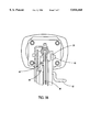
- FIGS. 1A and 1B A hook 11 is provided in a trigger 10, and an outer side of the hook 11 has a trigger bar 12 welded thereto for extension into a nail channel 20.
- the trigger bar 12 is provided with a groove 121.
- a retaining plate 22 in the nail channel 20 is disposed on a follow plate 21 and has a flange 221 for engaging the groove 121.
- a primary object of the present invention is to provide a no-idle-striking structure for pneumatic nailing machines, which is simple to assembly so as to reduce production costs and labor; besides, the structure is reliable and strong and may avoid possible damage to the cylinder, piston and strike pin of the nailing machine.
- the no-idle-striking structure of the present invention essentially comprises a bumper bar and a follow plate in which the bumper bar is provided with a hook and the follow plate is provided with a stop portion.
- FIGS. 1A and 1B are schematic views of the prior art
- FIGS. 2A, 2B and 2C are schematic views of the present invention.
- FIGS. 3A and 3B are schematic views illustrating the operation of the present invention.
- the present invention essentially comprises a strike assembly 30, a bumper bar 40, a magazine 50, and a follow plate 60.
- the strike assembly 30 is pivotally provided at a front end of a gun body and has a push bar 31 fitted thereon for urging against a workpiece.
- the push bar 31 has the bumper 40 fitted thereon and is urged by a spring 32 at a rear end thereof.
- a magazine support 33 is disposed below the strike assembly 30 and provided with an elongate hole 331 at the side adjacent to the bumper bar 40 for extension of a hook 43 thereinto.
- the bumper bar 40 has a rear end extending into the interior of a trigger and a front end bending upwardly to fit onto the push bar 31 so that it may achieve linking-up movement with the push bar 31.
- the bumper bar 40 is provided with an elongated circular hole 41 for passage of a screw bolt 42 which is locked to the magazine 50 so that it may not interfere with the movement of the bumper bar 40.
- the hook 43 is integrally formed and extends upwardly from the bumper bar 40. After bending, the hook 43 extends into the elongate hole 331 of the magazine support 33.
- the magazine 50 is internally provided with a slide groove 51 whereby the follow plate 60 and a slide element 63 thereof may slide in the magazine 50 for pushing the nails.
- One side of the slide groove 51 is provided with a slot 52.
- Screw holes 53 are formed at both sides of a top end of the magazine 50.
- An L-shaped slot 54 is provided at the side near the bumper bar 40.
- the follow plate 60 is essentially a plate structure.
- a front end of the follow plate 60 which is in contact with the nails forms an inclined surface with a depression 61 which may precisely guide the heads of the nails.
- a handle portion 52 is formed at a lateral side thereof for passing through the slot 52 of the magazine 50.
- On that side of the follow plate 60 which is one the same side of the bumper bar is disposed an integrally formed stop portion 64 which extends outwardly therefrom.
- the slide element 63 is provided near a rear end of the follow plate 60.
- a spring 631 is disposed in side the slide element 63 and engages the stop portion 64.
- the present invention provides a structure in which an integrally formed hook is disposed on the bumper bar to directly control the bumper bar, and a stop portion is correspondingly provided on the follow plate so that there is no-idle-striking when there are no more nails in the magazine.
Abstract
Description
Claims (1)
Priority Applications (1)
| Application Number | Priority Date | Filing Date | Title |
|---|---|---|---|
| US08/880,292 US5816468A (en) | 1997-06-24 | 1997-06-24 | No-idle-striking structure for nailing machines |
Applications Claiming Priority (1)
| Application Number | Priority Date | Filing Date | Title |
|---|---|---|---|
| US08/880,292 US5816468A (en) | 1997-06-24 | 1997-06-24 | No-idle-striking structure for nailing machines |
Publications (1)
| Publication Number | Publication Date |
|---|---|
| US5816468A true US5816468A (en) | 1998-10-06 |
Family
ID=25375974
Family Applications (1)
| Application Number | Title | Priority Date | Filing Date |
|---|---|---|---|
| US08/880,292 Expired - Fee Related US5816468A (en) | 1997-06-24 | 1997-06-24 | No-idle-striking structure for nailing machines |
Country Status (1)
| Country | Link |
|---|---|
| US (1) | US5816468A (en) |
Cited By (40)
| Publication number | Priority date | Publication date | Assignee | Title |
|---|---|---|---|---|
| WO2000059687A1 (en) * | 1999-04-05 | 2000-10-12 | Stanley Fastening Systems, L.P. | Safety trip assembly and trip lock mechanism for a fastener driving tool |
| US6149046A (en) * | 1999-11-01 | 2000-11-21 | Basso Industry Corp. | Safety device for preventing ejecting mechanism from hitting pushing member in a magazine of a power stapler |
| US6186386B1 (en) | 1999-08-06 | 2001-02-13 | Stanley Fastening Systems, Lp | Fastener driving device with enhanced depth adjusting assembly |
| US6199739B1 (en) * | 1998-08-10 | 2001-03-13 | Makita Corporation | Nail guns having means for preventing the nail driving operation |
| US20020121540A1 (en) * | 2001-03-01 | 2002-09-05 | Taylor Walter J. | Adjustable depth of drive device |
| US6454152B1 (en) * | 1998-12-04 | 2002-09-24 | Societe De Prospection Et D'inventions Techniques Spit | Apparatus for fastening plugs by compressed gas |
| US6592014B2 (en) | 2001-12-13 | 2003-07-15 | Illinois Tool Works Inc. | Lockout mechanism for fastener driving tool |
| US20040149800A1 (en) * | 2003-02-05 | 2004-08-05 | Stanley Fastening Systems, Lp | Depth of drive adjustment for a fastener driving tool with removable contact member and method of exchanging contact members |
| US20040222266A1 (en) * | 2003-02-07 | 2004-11-11 | Makita Corporation | Fastener driving tools |
| US20050184120A1 (en) * | 2004-02-20 | 2005-08-25 | Terrell Timothy E. | Dual mode pneumatic fastener actuation mechanism |
| US20060000863A1 (en) * | 2004-06-30 | 2006-01-05 | Stanley Fastening Systems, L.P. | Fastener driving device |
| US20060065692A1 (en) * | 2004-09-24 | 2006-03-30 | Taylor Walter J | Tool-free depth-of-drive adjustment for a fastener-driving tool |
| US7032794B1 (en) * | 2004-10-28 | 2006-04-25 | Basso Industry Corp. | Safety device for preventing a nailer from dry firing |
| US20060108390A1 (en) * | 2002-09-18 | 2006-05-25 | Schnell John W | Articulating pusher assembly |
| US20060213946A1 (en) * | 2005-03-28 | 2006-09-28 | Yury Shkolnikov | Power nailer with driver blade blocking mechanism magazine |
| US20060216233A1 (en) * | 1999-10-08 | 2006-09-28 | Young David S F | Cytotoxicity mediation of cells evidencing surface expression of CD44 |
| US20070290019A1 (en) * | 2006-05-30 | 2007-12-20 | Dierk Tille | Hand-held setting device |
| US20080264997A1 (en) * | 2005-11-09 | 2008-10-30 | Illinois Tool Works Inc. | Combustion Nailer Workpiece Contact Element With Enhanced Gripping |
| US20090039134A1 (en) * | 2005-05-25 | 2009-02-12 | Kouji Kubo | Driving Tool |
| US20090127310A1 (en) * | 2007-11-20 | 2009-05-21 | Chung Hung Yu | Block Device for Nail Gun |
| US20110062208A1 (en) * | 2009-09-15 | 2011-03-17 | Credo Technology Corporation | Fastener driver with driver assembly blocking member |
| US20110062207A1 (en) * | 2009-09-15 | 2011-03-17 | Credo Technology Corporation | Fastener driver with blank fire lockout |
| US8292143B2 (en) | 2010-10-12 | 2012-10-23 | Stanley Fastening Systems, L.P. | Dry fire lockout with bypass for fastener driving device |
| EP2591882A2 (en) * | 2011-11-11 | 2013-05-15 | Kwai King Cheung | Multifunctional nail gun |
| EP2666594A1 (en) * | 2010-09-29 | 2013-11-27 | Stanley Fastening Systems L.P. | Fastening tool |
| US20150202756A1 (en) * | 2012-07-25 | 2015-07-23 | Illinois Tool Works Inc. | Indirect firing fastening tool with anti-firing trigger support |
| USD756740S1 (en) | 2014-06-02 | 2016-05-24 | Stanley Fastening Systems, L.P. | Pneumatic nailer |
| USD756739S1 (en) | 2014-06-02 | 2016-05-24 | Stanley Fastening Systems, L.P. | Pneumatic nailer |
| USD758158S1 (en) * | 2014-11-20 | 2016-06-07 | Black & Decker Inc. | Fastening tool |
| US20180093370A1 (en) * | 2016-10-04 | 2018-04-05 | Stanley Black & Decker, Inc. | Fastening Tool with Contact Arm and Multi-Fastener Guide |
| US10173310B2 (en) | 2015-02-06 | 2019-01-08 | Milwaukee Electric Tool Corporation | Gas spring-powered fastener driver |
| US20190176311A1 (en) * | 2017-12-07 | 2019-06-13 | Basso Industry Corp. | Nailing device and adjustable nailing depth module thereof |
| CN111281789A (en) * | 2020-02-22 | 2020-06-16 | 高谦 | Intelligent internal hot needle punching machine |
| US10926385B2 (en) | 2017-02-24 | 2021-02-23 | Black & Decker, Inc. | Contact trip having magnetic filter |
| US10987790B2 (en) | 2016-06-30 | 2021-04-27 | Black & Decker Inc. | Cordless concrete nailer with improved power take-off mechanism |
| US11267114B2 (en) | 2016-06-29 | 2022-03-08 | Black & Decker, Inc. | Single-motion magazine retention for fastening tools |
| US11279013B2 (en) | 2016-06-30 | 2022-03-22 | Black & Decker, Inc. | Driver rebound plate for a fastening tool |
| US11325235B2 (en) | 2016-06-28 | 2022-05-10 | Black & Decker, Inc. | Push-on support member for fastening tools |
| US11400572B2 (en) | 2016-06-30 | 2022-08-02 | Black & Decker, Inc. | Dry-fire bypass for a fastening tool |
| US11878400B2 (en) | 2021-01-20 | 2024-01-23 | Milwaukee Electric Tool Corporation | Powered fastener driver |
Citations (5)
| Publication number | Priority date | Publication date | Assignee | Title |
|---|---|---|---|---|
| US4597517A (en) * | 1985-06-21 | 1986-07-01 | Signode Corporation | Magazine interlock for a fastener driving device |
| US4821937A (en) * | 1987-09-14 | 1989-04-18 | Duo-Fast Corporation | Guide for fastener driving tool |
| US5180091A (en) * | 1990-11-30 | 1993-01-19 | Makita Corporation | Nailing machine |
| US5485946A (en) * | 1993-04-16 | 1996-01-23 | Joh. Friedrich Behrens Ab | Release locking means of a driving tool for fasteners |
| US5593079A (en) * | 1994-03-11 | 1997-01-14 | Makita Corporation | Nailing machine |
-
1997
- 1997-06-24 US US08/880,292 patent/US5816468A/en not_active Expired - Fee Related
Patent Citations (5)
| Publication number | Priority date | Publication date | Assignee | Title |
|---|---|---|---|---|
| US4597517A (en) * | 1985-06-21 | 1986-07-01 | Signode Corporation | Magazine interlock for a fastener driving device |
| US4821937A (en) * | 1987-09-14 | 1989-04-18 | Duo-Fast Corporation | Guide for fastener driving tool |
| US5180091A (en) * | 1990-11-30 | 1993-01-19 | Makita Corporation | Nailing machine |
| US5485946A (en) * | 1993-04-16 | 1996-01-23 | Joh. Friedrich Behrens Ab | Release locking means of a driving tool for fasteners |
| US5593079A (en) * | 1994-03-11 | 1997-01-14 | Makita Corporation | Nailing machine |
Cited By (68)
| Publication number | Priority date | Publication date | Assignee | Title |
|---|---|---|---|---|
| US6199739B1 (en) * | 1998-08-10 | 2001-03-13 | Makita Corporation | Nail guns having means for preventing the nail driving operation |
| US6454152B1 (en) * | 1998-12-04 | 2002-09-24 | Societe De Prospection Et D'inventions Techniques Spit | Apparatus for fastening plugs by compressed gas |
| USRE38834E1 (en) | 1999-04-05 | 2005-10-18 | Stanley Fastening Systems, Lp | Safety trip assembly and trip lock mechanism for a fastener driving tool |
| US6209770B1 (en) | 1999-04-05 | 2001-04-03 | Stanley Fastening Systems, Lp | Safety trip assembly and trip lock mechanism for a fastener driving tool |
| WO2000059687A1 (en) * | 1999-04-05 | 2000-10-12 | Stanley Fastening Systems, L.P. | Safety trip assembly and trip lock mechanism for a fastener driving tool |
| US6186386B1 (en) | 1999-08-06 | 2001-02-13 | Stanley Fastening Systems, Lp | Fastener driving device with enhanced depth adjusting assembly |
| US20060216233A1 (en) * | 1999-10-08 | 2006-09-28 | Young David S F | Cytotoxicity mediation of cells evidencing surface expression of CD44 |
| US6149046A (en) * | 1999-11-01 | 2000-11-21 | Basso Industry Corp. | Safety device for preventing ejecting mechanism from hitting pushing member in a magazine of a power stapler |
| US20020121540A1 (en) * | 2001-03-01 | 2002-09-05 | Taylor Walter J. | Adjustable depth of drive device |
| US6988648B2 (en) | 2001-03-01 | 2006-01-24 | Illinois Tool Works Inc. | Adjustable depth of drive device |
| US6592014B2 (en) | 2001-12-13 | 2003-07-15 | Illinois Tool Works Inc. | Lockout mechanism for fastener driving tool |
| US20060108390A1 (en) * | 2002-09-18 | 2006-05-25 | Schnell John W | Articulating pusher assembly |
| USRE41265E1 (en) | 2003-02-05 | 2010-04-27 | Stanley Fastening Systems, L.P. | Depth of drive adjustment for a fastener driving tool with removable contact member and method of exchanging contact members |
| US6783044B2 (en) | 2003-02-05 | 2004-08-31 | Stanley Fastening Systems, L.P. | Depth of drive adjustment for a fastener driving tool with removable contact member and method of exchanging contact members |
| US20040149800A1 (en) * | 2003-02-05 | 2004-08-05 | Stanley Fastening Systems, Lp | Depth of drive adjustment for a fastener driving tool with removable contact member and method of exchanging contact members |
| US20040222266A1 (en) * | 2003-02-07 | 2004-11-11 | Makita Corporation | Fastener driving tools |
| US7000294B2 (en) * | 2003-02-07 | 2006-02-21 | Makita Corporation | Fastener driving tools |
| US7137540B2 (en) * | 2004-02-20 | 2006-11-21 | Black & Decker Inc. | Dual mode pneumatic fastener actuation mechanism |
| US20070034660A1 (en) * | 2004-02-20 | 2007-02-15 | Black & Decker Inc. | Dual mode pneumatic fastener actuation mechanism |
| US20050184120A1 (en) * | 2004-02-20 | 2005-08-25 | Terrell Timothy E. | Dual mode pneumatic fastener actuation mechanism |
| US7458492B2 (en) | 2004-02-20 | 2008-12-02 | Black & Decker Inc. | Dual mode pneumatic fastener actuation mechanism |
| US20060000863A1 (en) * | 2004-06-30 | 2006-01-05 | Stanley Fastening Systems, L.P. | Fastener driving device |
| US7134586B2 (en) | 2004-06-30 | 2006-11-14 | Stanley Fastening Systems, L.P. | Fastener driving device |
| US7055729B2 (en) | 2004-09-24 | 2006-06-06 | Illinois Tool Works Inc. | Tool-free depth-of-drive adjustment for a fastener-driving tool |
| US20060065692A1 (en) * | 2004-09-24 | 2006-03-30 | Taylor Walter J | Tool-free depth-of-drive adjustment for a fastener-driving tool |
| CN100581746C (en) * | 2004-09-24 | 2010-01-20 | 伊利诺斯器械工程公司 | Any drive depth adjustment tool for a fastener-driving tool |
| US7032794B1 (en) * | 2004-10-28 | 2006-04-25 | Basso Industry Corp. | Safety device for preventing a nailer from dry firing |
| US20060091175A1 (en) * | 2004-10-28 | 2006-05-04 | Basso Industry Corp. | Safety device for preventing a nailer from dry firing |
| US20060213946A1 (en) * | 2005-03-28 | 2006-09-28 | Yury Shkolnikov | Power nailer with driver blade blocking mechanism magazine |
| US7328826B2 (en) * | 2005-03-28 | 2008-02-12 | Illinois Tool Works Inc. | Power nailer with driver blade blocking mechanism magazine |
| JP4897789B2 (en) * | 2005-03-28 | 2012-03-14 | イリノイ トゥール ワークス インコーポレイティド | Power nailing machine with block mechanism of driving blade |
| US20090039134A1 (en) * | 2005-05-25 | 2009-02-12 | Kouji Kubo | Driving Tool |
| US7757920B2 (en) * | 2005-11-09 | 2010-07-20 | Illinois Tool Works Inc. | Combustion nailer workpiece contact element with enhanced gripping |
| US20080264997A1 (en) * | 2005-11-09 | 2008-10-30 | Illinois Tool Works Inc. | Combustion Nailer Workpiece Contact Element With Enhanced Gripping |
| US20070290019A1 (en) * | 2006-05-30 | 2007-12-20 | Dierk Tille | Hand-held setting device |
| US8104658B2 (en) * | 2007-11-20 | 2012-01-31 | De Poan Pneumatic Corp. | Block device for nail gun |
| US20090127310A1 (en) * | 2007-11-20 | 2009-05-21 | Chung Hung Yu | Block Device for Nail Gun |
| US8746526B2 (en) | 2009-09-15 | 2014-06-10 | Robert Bosch Gmbh | Fastener driver with blank fire lockout |
| US20110062208A1 (en) * | 2009-09-15 | 2011-03-17 | Credo Technology Corporation | Fastener driver with driver assembly blocking member |
| US20110062207A1 (en) * | 2009-09-15 | 2011-03-17 | Credo Technology Corporation | Fastener driver with blank fire lockout |
| US8336748B2 (en) | 2009-09-15 | 2012-12-25 | Robert Bosch Gmbh | Fastener driver with driver assembly blocking member |
| TWI554368B (en) * | 2009-12-04 | 2016-10-21 | 羅伯特博斯奇工具公司 | A device for driving a plurality of fasteners |
| US8833626B2 (en) | 2010-09-29 | 2014-09-16 | Stanley Fastening Systems, L.P. | Fastening tool |
| EP2666594A1 (en) * | 2010-09-29 | 2013-11-27 | Stanley Fastening Systems L.P. | Fastening tool |
| US9221161B2 (en) | 2010-09-29 | 2015-12-29 | Stanley Fastening Systems, L.P. | Fastening tool |
| US8292143B2 (en) | 2010-10-12 | 2012-10-23 | Stanley Fastening Systems, L.P. | Dry fire lockout with bypass for fastener driving device |
| EP2591882A3 (en) * | 2011-11-11 | 2014-06-25 | Kwai King Cheung | Multifunctional nail gun |
| EP2591882A2 (en) * | 2011-11-11 | 2013-05-15 | Kwai King Cheung | Multifunctional nail gun |
| US20150202756A1 (en) * | 2012-07-25 | 2015-07-23 | Illinois Tool Works Inc. | Indirect firing fastening tool with anti-firing trigger support |
| US10252406B2 (en) * | 2012-07-25 | 2019-04-09 | Illinois Tool Works Inc. | Indirect firing fastening tool with anti-firing trigger support |
| USD756739S1 (en) | 2014-06-02 | 2016-05-24 | Stanley Fastening Systems, L.P. | Pneumatic nailer |
| USD756740S1 (en) | 2014-06-02 | 2016-05-24 | Stanley Fastening Systems, L.P. | Pneumatic nailer |
| USD758158S1 (en) * | 2014-11-20 | 2016-06-07 | Black & Decker Inc. | Fastening tool |
| US11072058B2 (en) | 2015-02-06 | 2021-07-27 | Milwaukee Electric Tool Corporation | Gas spring-powered fastener driver |
| US11926028B2 (en) | 2015-02-06 | 2024-03-12 | Milwaukee Electric Tool Corporation | Gas spring-powered fastener driver |
| US10173310B2 (en) | 2015-02-06 | 2019-01-08 | Milwaukee Electric Tool Corporation | Gas spring-powered fastener driver |
| US11633842B2 (en) | 2015-02-06 | 2023-04-25 | Milwaukee Electric Tool Corporation | Gas spring-powered fastener driver |
| US11325235B2 (en) | 2016-06-28 | 2022-05-10 | Black & Decker, Inc. | Push-on support member for fastening tools |
| US11267114B2 (en) | 2016-06-29 | 2022-03-08 | Black & Decker, Inc. | Single-motion magazine retention for fastening tools |
| US10987790B2 (en) | 2016-06-30 | 2021-04-27 | Black & Decker Inc. | Cordless concrete nailer with improved power take-off mechanism |
| US11279013B2 (en) | 2016-06-30 | 2022-03-22 | Black & Decker, Inc. | Driver rebound plate for a fastening tool |
| US11400572B2 (en) | 2016-06-30 | 2022-08-02 | Black & Decker, Inc. | Dry-fire bypass for a fastening tool |
| US20180093370A1 (en) * | 2016-10-04 | 2018-04-05 | Stanley Black & Decker, Inc. | Fastening Tool with Contact Arm and Multi-Fastener Guide |
| US10926385B2 (en) | 2017-02-24 | 2021-02-23 | Black & Decker, Inc. | Contact trip having magnetic filter |
| US20190176311A1 (en) * | 2017-12-07 | 2019-06-13 | Basso Industry Corp. | Nailing device and adjustable nailing depth module thereof |
| CN111281789B (en) * | 2020-02-22 | 2022-02-18 | 高谦 | Intelligent internal hot needle punching machine |
| CN111281789A (en) * | 2020-02-22 | 2020-06-16 | 高谦 | Intelligent internal hot needle punching machine |
| US11878400B2 (en) | 2021-01-20 | 2024-01-23 | Milwaukee Electric Tool Corporation | Powered fastener driver |
Similar Documents
| Publication | Publication Date | Title |
|---|---|---|
| US5816468A (en) | No-idle-striking structure for nailing machines | |
| JP5034177B2 (en) | Driving tool safety device | |
| TWI239881B (en) | Fastener driving tool having contact arm in contact with workpiece | |
| US8074855B2 (en) | Bypass type follower assembly having a latch mechanism on the follower claw | |
| JP4525214B2 (en) | Driving machine | |
| US5332141A (en) | Nailing machine | |
| JP4761257B2 (en) | Fastener driving machine | |
| US8485407B2 (en) | Fastener feeding device for a driving tool | |
| JP5055817B2 (en) | Contact mechanism in driving tools | |
| US5370295A (en) | Feed mechanism for gravity feed tackers | |
| JP3289760B2 (en) | Nail hitting device | |
| JPS6048312B2 (en) | Automatic nailer's nail dry-driving prevention device | |
| JP2000354981A (en) | Blank driving prevention device for fastening machine | |
| JP4992199B2 (en) | Driving tool contact mechanism | |
| US7070081B2 (en) | Driver guides for use with fastener-driving tools and fastener-driving tools having such driver guides | |
| JPH0647668Y2 (en) | Ignition prevention mechanism for fastener driving tools | |
| JP4461638B2 (en) | Immersion prevention mechanism in tucker | |
| JP3045050U (en) | Nail feeding mechanism for nailing machine | |
| JP2002346950A (en) | Blank shot preventing mechanism for nailer | |
| JP2001025979A (en) | Nail guide device for nail machine | |
| JP2820045B2 (en) | Prevention device for idle driving of stapling machine | |
| JPH08257936A (en) | Mounted structure of contact foot | |
| JP3620365B2 (en) | Nail supply mechanism for nail nailing machine | |
| JP4032588B2 (en) | Washer nailer | |
| JPH0947978A (en) | No-load driving prevent device for fixing tool driving machine |
Legal Events
| Date | Code | Title | Description |
|---|---|---|---|
| AS | Assignment |
Owner name: TESTO INDUSTRY CORPORATION, TAIWAN Free format text: ASSIGNMENT OF ASSIGNORS INTEREST;ASSIGNOR:YANG, BRAD;REEL/FRAME:008911/0693 Effective date: 19970602 |
|
| FEPP | Fee payment procedure |
Free format text: PAYOR NUMBER ASSIGNED (ORIGINAL EVENT CODE: ASPN); ENTITY STATUS OF PATENT OWNER: SMALL ENTITY |
|
| REMI | Maintenance fee reminder mailed | ||
| FPAY | Fee payment |
Year of fee payment: 4 |
|
| SULP | Surcharge for late payment | ||
| FP | Lapsed due to failure to pay maintenance fee |
Effective date: 20021006 |
|
| REMI | Maintenance fee reminder mailed | ||
| LAPS | Lapse for failure to pay maintenance fees | ||
| STCH | Information on status: patent discontinuation |
Free format text: PATENT EXPIRED DUE TO NONPAYMENT OF MAINTENANCE FEES UNDER 37 CFR 1.362 |
|
| FP | Lapsed due to failure to pay maintenance fee |
Effective date: 20061006 |