US6148415A - Backup switching control system and method - Google Patents
Backup switching control system and method Download PDFInfo
- Publication number
- US6148415A US6148415A US08/258,235 US25823594A US6148415A US 6148415 A US6148415 A US 6148415A US 25823594 A US25823594 A US 25823594A US 6148415 A US6148415 A US 6148415A
- Authority
- US
- United States
- Prior art keywords
- processor
- operating
- backup
- machine
- data
- Prior art date
- Legal status (The legal status is an assumption and is not a legal conclusion. Google has not performed a legal analysis and makes no representation as to the accuracy of the status listed.)
- Expired - Fee Related
Links
Images
Classifications
-
- G—PHYSICS
- G06—COMPUTING; CALCULATING OR COUNTING
- G06F—ELECTRIC DIGITAL DATA PROCESSING
- G06F11/00—Error detection; Error correction; Monitoring
- G06F11/07—Responding to the occurrence of a fault, e.g. fault tolerance
- G06F11/16—Error detection or correction of the data by redundancy in hardware
- G06F11/20—Error detection or correction of the data by redundancy in hardware using active fault-masking, e.g. by switching out faulty elements or by switching in spare elements
- G06F11/202—Error detection or correction of the data by redundancy in hardware using active fault-masking, e.g. by switching out faulty elements or by switching in spare elements where processing functionality is redundant
- G06F11/2023—Failover techniques
- G06F11/2028—Failover techniques eliminating a faulty processor or activating a spare
-
- G—PHYSICS
- G06—COMPUTING; CALCULATING OR COUNTING
- G06F—ELECTRIC DIGITAL DATA PROCESSING
- G06F11/00—Error detection; Error correction; Monitoring
- G06F11/07—Responding to the occurrence of a fault, e.g. fault tolerance
- G06F11/16—Error detection or correction of the data by redundancy in hardware
- G06F11/20—Error detection or correction of the data by redundancy in hardware using active fault-masking, e.g. by switching out faulty elements or by switching in spare elements
- G06F11/202—Error detection or correction of the data by redundancy in hardware using active fault-masking, e.g. by switching out faulty elements or by switching in spare elements where processing functionality is redundant
- G06F11/2023—Failover techniques
- G06F11/2025—Failover techniques using centralised failover control functionality
-
- G—PHYSICS
- G06—COMPUTING; CALCULATING OR COUNTING
- G06F—ELECTRIC DIGITAL DATA PROCESSING
- G06F11/00—Error detection; Error correction; Monitoring
- G06F11/07—Responding to the occurrence of a fault, e.g. fault tolerance
- G06F11/16—Error detection or correction of the data by redundancy in hardware
- G06F11/20—Error detection or correction of the data by redundancy in hardware using active fault-masking, e.g. by switching out faulty elements or by switching in spare elements
- G06F11/202—Error detection or correction of the data by redundancy in hardware using active fault-masking, e.g. by switching out faulty elements or by switching in spare elements where processing functionality is redundant
- G06F11/2038—Error detection or correction of the data by redundancy in hardware using active fault-masking, e.g. by switching out faulty elements or by switching in spare elements where processing functionality is redundant with a single idle spare processing component
-
- G—PHYSICS
- G06—COMPUTING; CALCULATING OR COUNTING
- G06F—ELECTRIC DIGITAL DATA PROCESSING
- G06F11/00—Error detection; Error correction; Monitoring
- G06F11/07—Responding to the occurrence of a fault, e.g. fault tolerance
- G06F11/16—Error detection or correction of the data by redundancy in hardware
- G06F11/20—Error detection or correction of the data by redundancy in hardware using active fault-masking, e.g. by switching out faulty elements or by switching in spare elements
- G06F11/202—Error detection or correction of the data by redundancy in hardware using active fault-masking, e.g. by switching out faulty elements or by switching in spare elements where processing functionality is redundant
- G06F11/2048—Error detection or correction of the data by redundancy in hardware using active fault-masking, e.g. by switching out faulty elements or by switching in spare elements where processing functionality is redundant where the redundant components share neither address space nor persistent storage
Definitions
- the present invention relates to a system and method in a data processing system for controlling the switching between an operating machine and a backup machine within the system. More particularly, the invention relates to controlling the backup switching between substantially similar operating and backup machines when the operating machine becomes faulty so that the backup machine takes over the processing from the faulty operating machine automatically, rapidly, reliably and economically.
- a backup switching control method for use with a system comprising an operating processor and a backup processor having synchronizing means and failure information storing means each, both means being utilized during backup processing.
- the operating and backup processors placed under this backup switching control method each have a switching mechanism for exchanging therebetween a disconnection command, a dump acquisition command and a disconnection complete notice.
- the switching mechanism includes a reset function for forcing the currently operating processor to release the system resources it occupies.
- a time counting function for monitoring the time required from the receipt of a disconnection command by the operating processor to the output of a disconnection complete notice therefrom so that if the disconnection complete notice is not recognized within a predetermined period of time, the operating processor is reset.
- the system under the backup switching control method of the invention allows the backup processor to take over from the operating processor when the backup processor judges the operating processor to be inoperative and when the backup processor has verified that the operating processor has released the system resources it occupied.
- the backup processor has its switching mechanism initially transmit a disconnection command and a dump acquisition command to a target operating processor via the switching mechanism of the latter.
- the switching mechanism of the operating processor Upon receipt of the disconnection command, the switching mechanism of the operating processor forwards the command to the latter and starts counting the elapsed time until the output of a disconnection complete notice from the operating processor.
- the operating processor releases the system resources it has used and dumps failure information by data transfer to an auxiliary storage external of the operating processor. The release of the system resources and execution of the failure information dump process proceed concurrently or in parallel under suitable control of the operating system or a backup switching control system associated therewith.
- the operating processor Upon completion of the disconnection from the system, the operating processor notifies the backup processor of the completion of the disconnection. If the operating processor fails to complete the disconnection process within a predetermined period of time, the switching mechanism of the operating processor triggers a reset and notifies the backup processor of the completion of the forced disconnection.
- the backup processor utilizes the released system resources and takes over the processing from the now-failed operating processor. The disconnected processor then undergoes failure checks and, when the cause of the failure is overcome, stands by as a newly functioning backup processor that is ready to take over from the currently operating processor. In this manner, the backup switching procedure is automated and the communication conflict or contention between the operating and the backup processors for the system resources is prevented. In addition, by the present invention switching to the backup processor is executed quickly.
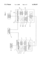
- FIG. 1 is a block diagram of a backup processor switching control system according to a first embodiment of the present invention.
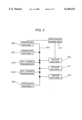
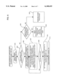
- FIG. 2 is a block diagram of a backup processor switching control system according to a second embodiment of the present invention.
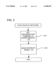
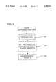
- FIG. 3 is a flowchart showing the steps performed in an initial phase of the backup switching control method according to the present invention.
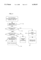
- FIG. 4 is a flowchart of the interrupt handling involving the main processors in both the operating and the backup processors.
- FIG. 5 is a flow chart of the steps followed in the disconnection task processing.
- FIG. 6 is a flowchart of the interrupt handling involving the auxiliary processors in both the operating and the backup processors.
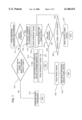
- FIG. 7 is a flowchart of the steps followed in the handling of notices communicated through the communication ports of the auxiliary processors.
- FIG. 1 shows the backup system of the invention which includes an operating data processor or machine 1 and a backup data processor or machine 101 placed under the backup switching control method of the invention.
- Processor 1 includes a main processor 2 and an auxiliary processor 6. Communication connections between the main processor 2 and the auxiliary processor 6 include an interrupt signal 3 sent from the main processor 2 to the auxiliary processor 6 and an interrupt signal 4 sent from the auxiliary processor 6 to the main processor 2.
- a shared memory 8 is connected to both processors 2 and 6 for reading and writing data.
- Main processor 2 also has memory that is not shared with the auxiliary processor 6, as well as registers, for storing data being processed.
- the processor 1 is arranged to be reset when a reset signal 5 is sent from the auxiliary processor 6 to the main processor 2.
- the auxiliary processor 6 includes a clock 9 and a communication port 7 connected with a communication channel 200.
- the embodiment of the invention shown in FIG. 1, includes one operating data processor and one backup data processor, each having a substantially identical configuration at least with respect to the inclusion in each of a main processor, auxiliary processor, shared memory and communication port.
- Auxiliary processor 6 and backup auxiliary processor 106 generally monitor such ambient conditions as temperature and supply voltage levels.
- the auxiliary processors are used to control switching between the backup processor and the operating processor upon failure of the latter.
- the auxiliary processors communicate with each other over a communication channel or network 200 through the communication port 7 and a backup communication port 107.
- the communication channel 200 may be either a wired channel or a wireless channel.
- the backup processor 101 starts disconnecting the operating processor 1 using the procedure of FIG. 3 and completes the disconnection process with the procedure of FIG. 4. It should be noted that the disconnection task processing of FIG. 5 is carried out in parallel with the failure information dump processing of FIG. 4 under control of the operating system of the main processor 2.
- the disconnection command of this embodiment also functions as a dump acquisition command, alternatively it is possible to separate the dump acquisition command from the disconnection command, whereby the contents of the shared memory can be separated from notices exchanged between the auxiliary processors.
- the backup auxiliary processor 106 retrieves from the memory 108 the disconnection command with which to disconnect the operating processor 1 (step 902), the backup auxiliary processor 106 sends a disconnection command to the auxiliary processor 6 of the operating processor 1 using the backup communication port 107 and via the communication channel 200 (step 906).
- the auxiliary processor 6 of the operating processor 1 writes the disconnection command to the shared memory 8 (step 916).
- the auxiliary processor 6 issues the interrupt signal 4 to the main processor 2 (step 917) and uses the clock 9 to count the elapsed time (step 918).
- the system of the invention operates in response to non-catastrophic failures in the operation of the operating processor, for example operational failures occurring in the execution of application software as a result of software or hardware error.
- a failure is minor enough for the main processor 2 to accept the interrupt signal 4
- the contents of the shared memory 8 are read (step 701 of FIG. 4). If what is read out is found to be the disconnection command (step 702), the disconnection task processing is started (step 706).
- the main processor 2 then disconnects itself from the system resources 50 (step 801 of FIG. 5) and concurrently dumps failure information, which includes data in a memory of main processor 2, and data being processed in the registers of the main processor 2 to an auxiliary storage device 60 (step 707).
- Auxiliary storage device 60 may be a hard disk, DAT or the like.
- the auxiliary processor 6 When the auxiliary processor 6 detects the interrupt signal 3 and receives the disconnection complete notice from the shared memory 8 within a predetermined period of time (step 920 of FIG. 7), the auxiliary processor 6 transmits a disconnection complete notice to the auxiliary processor 106 of the backup processor 101 through the communication port 7 and via the communication channel 200 (step 921). If the auxiliary processor 6 fails to detect the completion of the disconnection triggered by the interrupt signal 3 within the predetermined period of time (i.e., if 5 seconds, for example) elapses as determined by clock 9 and time is up without the disconnection completion notice being detected), the reset signal 5 is used to reset the main processor 2 (step 922). A reset-triggered disconnection complete notice is then transmitted to the auxiliary processor 106 in the backup processor 101 through the communication port 7 and via the communication channel 200 (step 923).
- the auxiliary processor 6 fails to detect the completion of the disconnection triggered by the interrupt signal 3 within the predetermined period of time (i.e., if 5 seconds, for example)
- the auxiliary processor 106 in the backup processor 101 receives the disconnection complete notice or reset-triggered disconnection complete notice through the communication port 107 (step 908 of FIG. 6), the auxiliary processor 106 sets the disconnection complete notice to the shared memory 108 (step 909). The auxiliary processor 106 then issues an interrupt signal 104 to the main processor 101 to inform the latter of the completion of the disconnection of the main processor 2 from the system resources 50 (step 910). Since the dump process may take a long time, one object of the invention is to control the switching of the failed operating processor to release the shared resources 50 and subsequently transmit the disconnection completion notice to the backup processor independently of completion of the dumping of the data by the main processor 2 to an external memory, e.g. auxiliary memory 60.
- an external memory e.g. auxiliary memory 60.
- the main processor 102 detects the interrupt signal 104 and receives the disconnection completion notice from the shared memory 108 (step 703 of FIG. 4), the main processor 102 takes over or exclusively occupies the system resources 50 and starts to carry out the data processing operations that would have been performed by the operating processor had the failure not occurred.
- the backup processor becomes a new operating processor that takes over from the now-failed operating processor in a short amount of time, not dependent on the completion of the dump processing. And further as a result, communication conflict between the operating and backup processors regarding the use of the system resources is avoided.
- a reset signal 105, a clock 109 and an auxiliary storage 160 of the backup processor are to be used when and if the newly operating processor (101) develops a failure and is replaced by a new backup processor (1), the switching therebetween taking place in the same manner as previously described. Accordingly, the disconnected processor (1) becomes the new backup processor after recovery from the failure that disabled it. If the new operating processor (101) fails, the remedied backup processor (1) is switched over in accordance with the present invention to again become the operation processor.
- two processors of substantially identical configuration can alternately function as the operating and backup processors.
- FIG. 2 Another embodiment of the invention will now be described with reference to a backup processor system shown in FIG. 2 having a plurality of operating data processors or machines 300, 301, . . . , 302 that are respectively connected to a corresponding plurality of backup data processors or machines 400, 401, . . . , 402 via a common communication channel 500.
- Each of the operating and backup machines are assigned a specific address.
- a particular operating machine is combined selectively with a particular backup machine by use of their addresses. Communication between the machines is effected on a local area network (LAN) basis.
- LAN local area network
- operating machine 300 and backup machine 400 share system resources 50-1, 50-2 and/or 50-3.
- System resources 50-1 are of the type connected directly between a designated combination of an operating machine 300 and a backup machine 400, while on the other hand, system resources 50-2 and 50-3 are directly connected to the network or communication channel 500 for use by one or more of the operating machines and functioning backup machines that have been switched into service in place of a failed operating machine.
- the status of operation is monitored so that the backup machines will be notified when a corresponding operating machine has a failure, such as an application program software failure or non-catastrophic hardware failure.
- the paired operating and backup machines can be directly connected to each other or indirectly connected through communication channel 500 so that a continuous checking of the status of the operating processor by the backup processor can be maintained and a notification of a failure of the operating processor transmitted to the backup processor through the connection thereof.
- the operating and backup processors may be connected to a service processor that monitors the operating condition of all of the operating machines so as to determine when a failure occurs with one of them. In this case, the failure would be communicated to the appropriate backup machine by the system machine or processor.
- the manner of determining whether a failure has occurred or not and of communicating or notifying the backup processor of the failure can be accomplished in any conventional manner.
- the switching between a given combination or pair of operating and backup machines is executed in the same manner as described above for the first embodiment of the invention by using communication channel 500 or another suitable connection between the respective machines, not shown, for sending and receiving the notices and other data between their communication ports.
- the backup processor has its auxiliary processor take over the processing of the currently operating processor when the latter releases the system resources needed to carry out the processing of the system. This prevents duplicate use of the system resources by the operating and the backup processors upon switching and thus optimizes the timing of the backup switching.
- it is possible to control the backup switching for a one-operating, one-backup machine system and also for a backup system involving a plurality of operating machines and a plurality of backup machines, all machines being substantially identically configured and connected to a common network or other interconnection.
- a highly economical backup system can be configured depending on the availability required for the system.
- the failed machine can assume its new role of a backup as soon as it recovers from the failure, with no interruption in the processing of the system. This also contributes to improving the availability of the system. Since failure information about the failed operating machine is automatically dumped, the timely information thus acquired facilitates the effort of troubleshooting. Even when large amounts of failure information about the failed operating machine are dumped over an extended period of time, the backup machine can take over the processing of the system without waiting for the dump to end.
Abstract
Description
Claims (21)
Applications Claiming Priority (2)
| Application Number | Priority Date | Filing Date | Title |
|---|---|---|---|
| JP5140449A JP3047275B2 (en) | 1993-06-11 | 1993-06-11 | Backup switching control method |
| JP5-140449 | 1993-06-11 |
Publications (1)
| Publication Number | Publication Date |
|---|---|
| US6148415A true US6148415A (en) | 2000-11-14 |
Family
ID=15268887
Family Applications (1)
| Application Number | Title | Priority Date | Filing Date |
|---|---|---|---|
| US08/258,235 Expired - Fee Related US6148415A (en) | 1993-06-11 | 1994-06-10 | Backup switching control system and method |
Country Status (2)
| Country | Link |
|---|---|
| US (1) | US6148415A (en) |
| JP (1) | JP3047275B2 (en) |
Cited By (45)
| Publication number | Priority date | Publication date | Assignee | Title |
|---|---|---|---|---|
| US6351829B1 (en) * | 1998-10-28 | 2002-02-26 | Honeywell Inc | System and method for distinguishing a device failure from an inter-device communication failure |
| US6411599B1 (en) * | 1998-05-29 | 2002-06-25 | International Business Machines Corporation | Fault tolerant switching architecture |
| US6449250B1 (en) * | 1998-01-28 | 2002-09-10 | Fujitsu Limited | Method for switching central device and a cable modem system using the same |
| US20020165629A1 (en) * | 2001-05-02 | 2002-11-07 | Taiwan Semiconductor Manufacturing Co., Ltd | Backup control system (BCS) for optimizing utilization of multiple fabrication facilities |
| US20020199023A1 (en) * | 2001-06-02 | 2002-12-26 | Ravi Chandra | Method and apparatus for process sync restart |
| US6502206B1 (en) * | 1998-12-15 | 2002-12-31 | Fujitsu Limited | Multi-processor switch and main processor switching method |
| US6570844B1 (en) * | 1997-12-29 | 2003-05-27 | Alcatel Usa Sourcing, L.P. | System and method for providing redundancy in a telecommunications system |
| US6651185B1 (en) * | 1999-12-16 | 2003-11-18 | Hewlett-Packard Development Company, L.P. | High availability platform with fast recovery from failure by reducing non-response time-outs |
| US20040010469A1 (en) * | 2002-07-09 | 2004-01-15 | Rohan Lenard | Method for authorizing a substitute software license server |
| US20040044901A1 (en) * | 2002-08-30 | 2004-03-04 | Serkowski Robert J. | License file serial number tracking |
| US6708286B2 (en) * | 1999-09-15 | 2004-03-16 | I-Bue Corporation | Standby SBC backplane |
| US20040078339A1 (en) * | 2002-10-22 | 2004-04-22 | Goringe Christopher M. | Priority based licensing |
| US20040172367A1 (en) * | 2003-02-27 | 2004-09-02 | Chavez David L. | Method and apparatus for license distribution |
| US20040181696A1 (en) * | 2003-03-11 | 2004-09-16 | Walker William T. | Temporary password login |
| US20040199799A1 (en) * | 2003-01-13 | 2004-10-07 | Arm Limited | Data processing performance control |
| US20040199760A1 (en) * | 2003-04-01 | 2004-10-07 | Mazza Bruce P. | Ironclad notification of license errors |
| US20050196314A1 (en) * | 2004-03-04 | 2005-09-08 | Minntech Corporation | On board monitor for endoscope reprocessor |
| US20050229022A1 (en) * | 2004-03-31 | 2005-10-13 | Nec Corporation | Data mirror cluster system, method and computer program for synchronizing data in data mirror cluster system |
| US20050240826A1 (en) * | 2004-04-08 | 2005-10-27 | International Business Machines Corporation | Method, data processing system, and computer program product for collecting first failure data capture information |
| US20050246590A1 (en) * | 2004-04-15 | 2005-11-03 | Lancaster Peter C | Efficient real-time analysis method of error logs for autonomous systems |
| US20060070743A1 (en) * | 2004-10-05 | 2006-04-06 | Halliburton Energy Services, Inc. | Surface instrumentation configuration for drilling rig operation |
| US7054892B1 (en) * | 1999-12-23 | 2006-05-30 | Emc Corporation | Method and apparatus for managing information related to storage activities of data storage systems |
| US20060150005A1 (en) * | 2004-12-21 | 2006-07-06 | Nec Corporation | Fault tolerant computer system and interrupt control method for the same |
| US20060212669A1 (en) * | 2005-03-17 | 2006-09-21 | Fujitsu Limited | Control method for storage system, storage system, storage control apparatus, control program for storage system, and information processing system |
| US20060294422A1 (en) * | 2005-06-28 | 2006-12-28 | Nec Electronics Corporation | Processor and method of controlling execution of processes |
| US20070061613A1 (en) * | 2005-09-15 | 2007-03-15 | Yusuke Ohashi | Restart method for operating system |
| US7216363B2 (en) | 2002-08-30 | 2007-05-08 | Avaya Technology Corp. | Licensing duplicated systems |
| US20070142932A1 (en) * | 2005-12-15 | 2007-06-21 | Honeywell Asca, Inc. | Technique for switching between controllers |
| US7272500B1 (en) | 2004-03-25 | 2007-09-18 | Avaya Technology Corp. | Global positioning system hardware key for software licenses |
| US20080059778A1 (en) * | 2006-09-06 | 2008-03-06 | International Business Machines Corporation | Determination Of Running Status Of Logical Processor |
| US7353388B1 (en) | 2004-02-09 | 2008-04-01 | Avaya Technology Corp. | Key server for securing IP telephony registration, control, and maintenance |
| US7373657B2 (en) | 2003-03-10 | 2008-05-13 | Avaya Technology Corp. | Method and apparatus for controlling data and software access |
| US7681245B2 (en) | 2002-08-30 | 2010-03-16 | Avaya Inc. | Remote feature activator feature extraction |
| US7698225B2 (en) | 2002-08-30 | 2010-04-13 | Avaya Inc. | License modes in call processing |
| US7707405B1 (en) | 2004-09-21 | 2010-04-27 | Avaya Inc. | Secure installation activation |
| US7707116B2 (en) | 2002-08-30 | 2010-04-27 | Avaya Inc. | Flexible license file feature controls |
| US7747851B1 (en) | 2004-09-30 | 2010-06-29 | Avaya Inc. | Certificate distribution via license files |
| US7814023B1 (en) | 2005-09-08 | 2010-10-12 | Avaya Inc. | Secure download manager |
| US7890997B2 (en) | 2002-12-26 | 2011-02-15 | Avaya Inc. | Remote feature activation authentication file system |
| US7965701B1 (en) | 2004-09-30 | 2011-06-21 | Avaya Inc. | Method and system for secure communications with IP telephony appliance |
| US7966520B2 (en) * | 2002-08-30 | 2011-06-21 | Avaya Inc. | Software licensing for spare processors |
| US8041642B2 (en) | 2002-07-10 | 2011-10-18 | Avaya Inc. | Predictive software license balancing |
| US8229858B1 (en) | 2004-09-30 | 2012-07-24 | Avaya Inc. | Generation of enterprise-wide licenses in a customer environment |
| US8661290B2 (en) | 2011-01-14 | 2014-02-25 | International Business Machines Corporation | Saving power in computing systems with redundant service processors |
| CN106326087A (en) * | 2016-08-31 | 2017-01-11 | 北京光年无限科技有限公司 | Webpage experiencing method based on robot operating system and system thereof |
Families Citing this family (7)
| Publication number | Priority date | Publication date | Assignee | Title |
|---|---|---|---|---|
| WO1999026138A1 (en) * | 1997-11-14 | 1999-05-27 | Hitachi, Ltd. | Method of changing over a multiplex system |
| DE10036573C2 (en) * | 2000-07-27 | 2002-06-27 | Bosch Gmbh Robert | Anti-theft alarm system with a control unit for controlling a siren |
| JP2002073378A (en) * | 2000-09-04 | 2002-03-12 | Hitachi Ltd | Method and device for obtaining dump of computer system |
| JP2004246621A (en) * | 2003-02-13 | 2004-09-02 | Fujitsu Ltd | Information collecting program, information collecting device, and information collecting method |
| JP4645837B2 (en) * | 2005-10-31 | 2011-03-09 | 日本電気株式会社 | Memory dump method, computer system, and program |
| JP2013254333A (en) * | 2012-06-06 | 2013-12-19 | Hitachi Ltd | Multiple system control system and control method therefor |
| JP6436066B2 (en) * | 2015-11-18 | 2018-12-12 | 京セラドキュメントソリューションズ株式会社 | Image forming apparatus and synchronization program |
Citations (11)
| Publication number | Priority date | Publication date | Assignee | Title |
|---|---|---|---|---|
| JPS5430383A (en) * | 1977-08-10 | 1979-03-06 | Hitachi Ltd | Back-up system of digital process controlling apparatus |
| JPS54107242A (en) * | 1978-02-10 | 1979-08-22 | Hitachi Ltd | Backup system for digital-system controller |
| GB2032149A (en) * | 1978-09-08 | 1980-04-30 | Fujitsu Ltd | Transferring from Working to Standby Processor on Fault |
| JPS57111752A (en) * | 1980-12-29 | 1982-07-12 | Fujitsu Ltd | Automatic system switching system |
| JPS6375843A (en) * | 1986-09-18 | 1988-04-06 | Fujitsu Ltd | Abnormality monitor system |
| US4819232A (en) * | 1985-12-17 | 1989-04-04 | Bbc Brown, Boveri & Company, Limited | Fault-tolerant multiprocessor arrangement |
| US5111384A (en) * | 1990-02-16 | 1992-05-05 | Bull Hn Information Systems Inc. | System for performing dump analysis |
| US5157663A (en) * | 1990-09-24 | 1992-10-20 | Novell, Inc. | Fault tolerant computer system |
| US5202980A (en) * | 1989-06-30 | 1993-04-13 | Nec Corporation | Information processing system capable of readily taking over processing of a faulty processor |
| US5255367A (en) * | 1987-09-04 | 1993-10-19 | Digital Equipment Corporation | Fault tolerant, synchronized twin computer system with error checking of I/O communication |
| US5307481A (en) * | 1990-02-28 | 1994-04-26 | Hitachi, Ltd. | Highly reliable online system |
-
1993
- 1993-06-11 JP JP5140449A patent/JP3047275B2/en not_active Expired - Lifetime
-
1994
- 1994-06-10 US US08/258,235 patent/US6148415A/en not_active Expired - Fee Related
Patent Citations (11)
| Publication number | Priority date | Publication date | Assignee | Title |
|---|---|---|---|---|
| JPS5430383A (en) * | 1977-08-10 | 1979-03-06 | Hitachi Ltd | Back-up system of digital process controlling apparatus |
| JPS54107242A (en) * | 1978-02-10 | 1979-08-22 | Hitachi Ltd | Backup system for digital-system controller |
| GB2032149A (en) * | 1978-09-08 | 1980-04-30 | Fujitsu Ltd | Transferring from Working to Standby Processor on Fault |
| JPS57111752A (en) * | 1980-12-29 | 1982-07-12 | Fujitsu Ltd | Automatic system switching system |
| US4819232A (en) * | 1985-12-17 | 1989-04-04 | Bbc Brown, Boveri & Company, Limited | Fault-tolerant multiprocessor arrangement |
| JPS6375843A (en) * | 1986-09-18 | 1988-04-06 | Fujitsu Ltd | Abnormality monitor system |
| US5255367A (en) * | 1987-09-04 | 1993-10-19 | Digital Equipment Corporation | Fault tolerant, synchronized twin computer system with error checking of I/O communication |
| US5202980A (en) * | 1989-06-30 | 1993-04-13 | Nec Corporation | Information processing system capable of readily taking over processing of a faulty processor |
| US5111384A (en) * | 1990-02-16 | 1992-05-05 | Bull Hn Information Systems Inc. | System for performing dump analysis |
| US5307481A (en) * | 1990-02-28 | 1994-04-26 | Hitachi, Ltd. | Highly reliable online system |
| US5157663A (en) * | 1990-09-24 | 1992-10-20 | Novell, Inc. | Fault tolerant computer system |
Non-Patent Citations (5)
| Title |
|---|
| Gaertner at al., Architecture for a Highly Reliable Parallel Computer System, Gaertner Research, Oct. 1975, at Abstract. * |
| Katsuki et al., Pluribus An Operational Fault Tolerant Processor, Proceedings of the IEEE, Oct. 1978, at 1146. * |
| Katsuki et al., Pluribus--An Operational Fault-Tolerant Processor, Proceedings of the IEEE, Oct. 1978, at 1146. |
| Schulman, Stalking GP Faults: Parts II, Dr. Dobb s Journal, Feb. 1990, at 76. * |
| Schulman, Stalking GP Faults: Parts II, Dr. Dobb's Journal, Feb. 1990, at 76. |
Cited By (71)
| Publication number | Priority date | Publication date | Assignee | Title |
|---|---|---|---|---|
| US6570844B1 (en) * | 1997-12-29 | 2003-05-27 | Alcatel Usa Sourcing, L.P. | System and method for providing redundancy in a telecommunications system |
| US6449250B1 (en) * | 1998-01-28 | 2002-09-10 | Fujitsu Limited | Method for switching central device and a cable modem system using the same |
| US6411599B1 (en) * | 1998-05-29 | 2002-06-25 | International Business Machines Corporation | Fault tolerant switching architecture |
| US6351829B1 (en) * | 1998-10-28 | 2002-02-26 | Honeywell Inc | System and method for distinguishing a device failure from an inter-device communication failure |
| US6502206B1 (en) * | 1998-12-15 | 2002-12-31 | Fujitsu Limited | Multi-processor switch and main processor switching method |
| US6708286B2 (en) * | 1999-09-15 | 2004-03-16 | I-Bue Corporation | Standby SBC backplane |
| US6651185B1 (en) * | 1999-12-16 | 2003-11-18 | Hewlett-Packard Development Company, L.P. | High availability platform with fast recovery from failure by reducing non-response time-outs |
| US7346636B2 (en) | 1999-12-23 | 2008-03-18 | Emc Corporation | Method and apparatus for managing information related to storage activities of data storage systems |
| US7054892B1 (en) * | 1999-12-23 | 2006-05-30 | Emc Corporation | Method and apparatus for managing information related to storage activities of data storage systems |
| US8321378B2 (en) | 1999-12-23 | 2012-11-27 | Emc Corporation | Method and apparatus for managing information related to storage activities of data storage systems |
| US6678566B2 (en) * | 2001-05-02 | 2004-01-13 | Taiwan Semiconductor Manufacturing Co., Ltd. | Backup control system (BCS) for optimizing utilization of multiple fabrication facilities |
| US20020165629A1 (en) * | 2001-05-02 | 2002-11-07 | Taiwan Semiconductor Manufacturing Co., Ltd | Backup control system (BCS) for optimizing utilization of multiple fabrication facilities |
| US20020199023A1 (en) * | 2001-06-02 | 2002-12-26 | Ravi Chandra | Method and apparatus for process sync restart |
| US8423674B2 (en) * | 2001-06-02 | 2013-04-16 | Ericsson Ab | Method and apparatus for process sync restart |
| US7885896B2 (en) * | 2002-07-09 | 2011-02-08 | Avaya Inc. | Method for authorizing a substitute software license server |
| US20040010469A1 (en) * | 2002-07-09 | 2004-01-15 | Rohan Lenard | Method for authorizing a substitute software license server |
| US8041642B2 (en) | 2002-07-10 | 2011-10-18 | Avaya Inc. | Predictive software license balancing |
| US7216363B2 (en) | 2002-08-30 | 2007-05-08 | Avaya Technology Corp. | Licensing duplicated systems |
| US7681245B2 (en) | 2002-08-30 | 2010-03-16 | Avaya Inc. | Remote feature activator feature extraction |
| US8620819B2 (en) | 2002-08-30 | 2013-12-31 | Avaya Inc. | Remote feature activator feature extraction |
| US7698225B2 (en) | 2002-08-30 | 2010-04-13 | Avaya Inc. | License modes in call processing |
| US7707116B2 (en) | 2002-08-30 | 2010-04-27 | Avaya Inc. | Flexible license file feature controls |
| US20040044901A1 (en) * | 2002-08-30 | 2004-03-04 | Serkowski Robert J. | License file serial number tracking |
| US7966520B2 (en) * | 2002-08-30 | 2011-06-21 | Avaya Inc. | Software licensing for spare processors |
| US7228567B2 (en) | 2002-08-30 | 2007-06-05 | Avaya Technology Corp. | License file serial number tracking |
| US7844572B2 (en) | 2002-08-30 | 2010-11-30 | Avaya Inc. | Remote feature activator feature extraction |
| US20040078339A1 (en) * | 2002-10-22 | 2004-04-22 | Goringe Christopher M. | Priority based licensing |
| US7890997B2 (en) | 2002-12-26 | 2011-02-15 | Avaya Inc. | Remote feature activation authentication file system |
| US7913301B2 (en) | 2002-12-26 | 2011-03-22 | Avaya Inc. | Remote feature activation authentication file system |
| US20040199799A1 (en) * | 2003-01-13 | 2004-10-07 | Arm Limited | Data processing performance control |
| US7600141B2 (en) * | 2003-01-13 | 2009-10-06 | Arm Limited | Data processing performance control |
| US7260557B2 (en) | 2003-02-27 | 2007-08-21 | Avaya Technology Corp. | Method and apparatus for license distribution |
| US20040172367A1 (en) * | 2003-02-27 | 2004-09-02 | Chavez David L. | Method and apparatus for license distribution |
| US7373657B2 (en) | 2003-03-10 | 2008-05-13 | Avaya Technology Corp. | Method and apparatus for controlling data and software access |
| US20040181696A1 (en) * | 2003-03-11 | 2004-09-16 | Walker William T. | Temporary password login |
| US7127442B2 (en) | 2003-04-01 | 2006-10-24 | Avaya Technology Corp. | Ironclad notification of license errors |
| US20040199760A1 (en) * | 2003-04-01 | 2004-10-07 | Mazza Bruce P. | Ironclad notification of license errors |
| US7353388B1 (en) | 2004-02-09 | 2008-04-01 | Avaya Technology Corp. | Key server for securing IP telephony registration, control, and maintenance |
| US20050196314A1 (en) * | 2004-03-04 | 2005-09-08 | Minntech Corporation | On board monitor for endoscope reprocessor |
| US7850905B2 (en) * | 2004-03-04 | 2010-12-14 | Minntech Corporation | On board monitor for endoscope reprocessor |
| US7272500B1 (en) | 2004-03-25 | 2007-09-18 | Avaya Technology Corp. | Global positioning system hardware key for software licenses |
| US7844852B2 (en) * | 2004-03-31 | 2010-11-30 | Nec Corporation | Data mirror cluster system, method and computer program for synchronizing data in data mirror cluster system |
| US20050229022A1 (en) * | 2004-03-31 | 2005-10-13 | Nec Corporation | Data mirror cluster system, method and computer program for synchronizing data in data mirror cluster system |
| US7308609B2 (en) | 2004-04-08 | 2007-12-11 | International Business Machines Corporation | Method, data processing system, and computer program product for collecting first failure data capture information |
| US20050240826A1 (en) * | 2004-04-08 | 2005-10-27 | International Business Machines Corporation | Method, data processing system, and computer program product for collecting first failure data capture information |
| US20050246590A1 (en) * | 2004-04-15 | 2005-11-03 | Lancaster Peter C | Efficient real-time analysis method of error logs for autonomous systems |
| US7225368B2 (en) | 2004-04-15 | 2007-05-29 | International Business Machines Corporation | Efficient real-time analysis method of error logs for autonomous systems |
| US7707405B1 (en) | 2004-09-21 | 2010-04-27 | Avaya Inc. | Secure installation activation |
| US8229858B1 (en) | 2004-09-30 | 2012-07-24 | Avaya Inc. | Generation of enterprise-wide licenses in a customer environment |
| US7747851B1 (en) | 2004-09-30 | 2010-06-29 | Avaya Inc. | Certificate distribution via license files |
| US7965701B1 (en) | 2004-09-30 | 2011-06-21 | Avaya Inc. | Method and system for secure communications with IP telephony appliance |
| US10503877B2 (en) | 2004-09-30 | 2019-12-10 | Avaya Inc. | Generation of enterprise-wide licenses in a customer environment |
| US20060070743A1 (en) * | 2004-10-05 | 2006-04-06 | Halliburton Energy Services, Inc. | Surface instrumentation configuration for drilling rig operation |
| US20060150005A1 (en) * | 2004-12-21 | 2006-07-06 | Nec Corporation | Fault tolerant computer system and interrupt control method for the same |
| US7441150B2 (en) * | 2004-12-21 | 2008-10-21 | Nec Corporation | Fault tolerant computer system and interrupt control method for the same |
| US20060212669A1 (en) * | 2005-03-17 | 2006-09-21 | Fujitsu Limited | Control method for storage system, storage system, storage control apparatus, control program for storage system, and information processing system |
| US9342416B2 (en) | 2005-06-28 | 2016-05-17 | Renesas Electronics Corporation | Processor and method of controlling execution of processes |
| US8984334B2 (en) | 2005-06-28 | 2015-03-17 | Renesas Electronics Corporation | Processor and method of controlling execution of processes |
| US20060294422A1 (en) * | 2005-06-28 | 2006-12-28 | Nec Electronics Corporation | Processor and method of controlling execution of processes |
| US10235254B2 (en) | 2005-06-28 | 2019-03-19 | Renesas Electronics Corporation | Processor and method of controlling execution of processes |
| US8296602B2 (en) * | 2005-06-28 | 2012-10-23 | Renesas Electronics Corporation | Processor and method of controlling execution of processes |
| US7814023B1 (en) | 2005-09-08 | 2010-10-12 | Avaya Inc. | Secure download manager |
| US20070061613A1 (en) * | 2005-09-15 | 2007-03-15 | Yusuke Ohashi | Restart method for operating system |
| US20070142932A1 (en) * | 2005-12-15 | 2007-06-21 | Honeywell Asca, Inc. | Technique for switching between controllers |
| US7515975B2 (en) * | 2005-12-15 | 2009-04-07 | Honeywell Asca Inc. | Technique for switching between controllers |
| US8276151B2 (en) * | 2006-09-06 | 2012-09-25 | International Business Machines Corporation | Determination of running status of logical processor |
| US8689230B2 (en) | 2006-09-06 | 2014-04-01 | International Business Machines Corporation | Determination of running status of logical processor |
| US20080059778A1 (en) * | 2006-09-06 | 2008-03-06 | International Business Machines Corporation | Determination Of Running Status Of Logical Processor |
| US8661290B2 (en) | 2011-01-14 | 2014-02-25 | International Business Machines Corporation | Saving power in computing systems with redundant service processors |
| CN106326087A (en) * | 2016-08-31 | 2017-01-11 | 北京光年无限科技有限公司 | Webpage experiencing method based on robot operating system and system thereof |
| CN106326087B (en) * | 2016-08-31 | 2019-04-19 | 北京光年无限科技有限公司 | Web page experience method and system based on robot operating system |
Also Published As
| Publication number | Publication date |
|---|---|
| JP3047275B2 (en) | 2000-05-29 |
| JPH06348528A (en) | 1994-12-22 |
Similar Documents
| Publication | Publication Date | Title |
|---|---|---|
| US6148415A (en) | Backup switching control system and method | |
| CN101714108A (en) | Synchronization control apparatus, information processing apparatus, and synchronization management method | |
| JPH086910A (en) | Cluster type computer system | |
| JP3806600B2 (en) | System switching method for multi-system | |
| JP3420919B2 (en) | Information processing device | |
| JPH07141308A (en) | Back-up method in information processing system | |
| JP3313667B2 (en) | Failure detection method and method for redundant system | |
| JPH06197112A (en) | Management system | |
| JPH04360242A (en) | Device and method for switching systems in duplexed system | |
| JP2001175545A (en) | Server system, fault diagnosing method, and recording medium | |
| JPH05224964A (en) | Bus abnormality information system | |
| JPH08329023A (en) | Parallel electronic computer system | |
| JPS5870670A (en) | Failure information transfer system for exchange of duplex system | |
| JPS6375843A (en) | Abnormality monitor system | |
| JP3169488B2 (en) | Communication control device | |
| JPS634210B2 (en) | ||
| JPH0652000A (en) | Data transfer method | |
| JPH11259324A (en) | Main storage device copying system | |
| JP2658215B2 (en) | Automatic transaction equipment | |
| JPS58103060A (en) | Multiplexed calculation processing system | |
| JP2002182994A (en) | Information processing system and transfer control method using it | |
| JPS63279646A (en) | Automatic restart processing system for network management equipment | |
| JPH0635736A (en) | Duplex processor | |
| JPH08227407A (en) | Data sharing device of multicomputer system | |
| JPH0341863B2 (en) |
Legal Events
| Date | Code | Title | Description |
|---|---|---|---|
| AS | Assignment |
Owner name: HITACHI, LTD., JAPAN Free format text: ASSIGNMENT OF ASSIGNORS INTEREST;ASSIGNORS:KOBAYASHI, ATUO;ISHII, YASUHIRO;REEL/FRAME:011000/0656 Effective date: 19940801 Owner name: HITACHI COMPUTER ENGINEERING CO., LTD., JAPAN Free format text: ASSIGNMENT OF ASSIGNORS INTEREST;ASSIGNORS:KOBAYASHI, ATUO;ISHII, YASUHIRO;REEL/FRAME:011000/0656 Effective date: 19940801 |
|
| FEPP | Fee payment procedure |
Free format text: PAYOR NUMBER ASSIGNED (ORIGINAL EVENT CODE: ASPN); ENTITY STATUS OF PATENT OWNER: LARGE ENTITY |
|
| FPAY | Fee payment |
Year of fee payment: 4 |
|
| REMI | Maintenance fee reminder mailed | ||
| LAPS | Lapse for failure to pay maintenance fees | ||
| STCH | Information on status: patent discontinuation |
Free format text: PATENT EXPIRED DUE TO NONPAYMENT OF MAINTENANCE FEES UNDER 37 CFR 1.362 |
|
| FP | Lapsed due to failure to pay maintenance fee |
Effective date: 20081114 |