US6494335B1 - Two frame collapsible structure and method of making and using same - Google Patents
Two frame collapsible structure and method of making and using same Download PDFInfo
- Publication number
- US6494335B1 US6494335B1 US09/698,674 US69867400A US6494335B1 US 6494335 B1 US6494335 B1 US 6494335B1 US 69867400 A US69867400 A US 69867400A US 6494335 B1 US6494335 B1 US 6494335B1
- Authority
- US
- United States
- Prior art keywords
- side panels
- collapsible structure
- frame
- edging
- panel
- Prior art date
- Legal status (The legal status is an assumption and is not a legal conclusion. Google has not performed a legal analysis and makes no representation as to the accuracy of the status listed.)
- Expired - Fee Related
Links
Images


Classifications
-
- D—TEXTILES; PAPER
- D06—TREATMENT OF TEXTILES OR THE LIKE; LAUNDERING; FLEXIBLE MATERIALS NOT OTHERWISE PROVIDED FOR
- D06F—LAUNDERING, DRYING, IRONING, PRESSING OR FOLDING TEXTILE ARTICLES
- D06F95/00—Laundry systems or arrangements of apparatus or machines; Mobile laundries
- D06F95/002—Baskets or bags specially adapted for holding or transporting laundry; Supports therefor
- D06F95/004—Bags; Supports therefor
Definitions
- the present invention can be utilized for garment sorting, storage and transportation.
- the present invention can also be utilized as an organizer for various objects.
- the present invention may be used to organize objects normally found in the trunk of a car.
- the present invention can also be used for other purposes, such as the storage or transportation of toys or other objects.
- the present invention could be used as a child's play structure or pet den structure. Accordingly, its use is multipurpose as both a container and structure.
- U.S. Pat. No. 2,625,973 to Weldon et al. teaches a laundry hamper comprising a rectangular frame having upper and lower portions that telescope within one another in a detachable manner.
- the lower portion includes a base frame, while the upper portion comprises a top frame.
- a cover is secured by a hinge to the top frame and an outer bag surrounds the rectangular frame.
- a plurality of small inner bags are provided within the outer bag.
- U.S. Pat No. 1,581,888 to Thomas discloses a collapsible receptacle comprising two rectangular wire frames, hingedly secured together, means for holding the frames to form a triangularly shaped structure, and a fabric portion covering the frames and providing an enclosure.
- the present invention solves the above-mentioned shortcomings and provides a convenient, easy to manipulate, and ergonomic means for storing or transporting garments or other objects.
- the present invention relates generally to a collapsible structure and specifically to a collapsible structure for storing articles or forming a child's toy and method of making and using the same.
- each side panel comprises a flexible continuous loop frame, a web of material, and an edging material.
- the edging envelops the frame and is coupled to the periphery of the web.
- the floor panel is attached to the bottom side of each side panel thus forming the structure.
- each side panel is attached to a side panel separator, which in turn is connected to the next adjacent side panel.
- the floor panel is attached to both the bottom side of each side panel and to the side panel separators, thus providing means for holding articles within the structure and for supporting the structure in its expanded state.
- a single frame member forms the frame structure for two side panels.
- Each side panel comprises a web of material and an edging material.
- the edging material is attached to portions of the web.
- the edging partially envelops the frame and is coupled to predetermined portions of the periphery of the web.
- the floor panel is attached to the bottom side of each side panel, thus forming the structure.
- At least one handle member is coupled to opposite side panels at the open top of the structure.
- the handle may be coupled to only one side panel or may be an aperture formed within one or more of the side panels.
- an optional storage pouch may be coupled to one of the side panels at the open top of the structure.
- the present invention is easily collapsed into a compact state and the pouch allows storage of the structure in its collapsed, compact state.
- the collapsible structure further comprises a divider panel, the divided panel being attached to diagonally opposite edgings of the side panels.
- the collapsible structure further comprises at least two divider panels, preferably arranged substantially parallel to each other and being coupled to opposite side panels to create at least three separate compartments within the structure.
- a preferred method of manufacturing the collapsible structure includes the steps of attaching each handle member to a side of two opposite webs.
- the edging is next coupled to each web such that the edging surrounds the perimeter of the web and forms a channel or pocket through which the frame will later be inserted.
- each side of the floor panel is attached to the bottom side of each side panel.
- a side of each side panel is connected with a side of an adjacent side panel.
- the frame for each side panel is inserted through the channel formed by each edging.
- the ends of each frame member are connected, preferably using a crimped butt connector, to give the collapsible structure its ability to freely stand in a rigid, expanded, upright state.
- An alternative method of manufacturing the collapsible structure includes the steps of supplying two attached webs of material. Next, edging is coupled to each web such that the edging substantially surrounds the perimeter of each web and forms a channel or pocket through which the frame will later be inserted. An opening in the webbing is left along the respective sides where the two webs are contiguous. A two-web side panel is thus formed. After a pair of two-web side panels have been formed, a single frame is inserted through the channel formed by the edging of each two-web side panel. Each frame first is threaded through the edging surrounding one web and then is threaded through the edging surrounding the second, contiguous web.
- each frame member is connected, preferably using a crimped butt connector, in a “figure eight” configuration to give the collapsible structure its ability to freely stand in a rigid, expanded, upright state.
- the second two-web side panel is completed by the same steps. The pair of two-web side panels are connected together and a floor panel is attached along the lower edge of each side panel.
- Yet another alternative method of manufacturing the collapsible structure includes the steps of attaching each handle member to a side of two opposite webs. Coupling the edging to each web such that the edging surrounds the perimeter of the web and forms a channel or pocket through which the frame will later be inserted. After the requisite number of side panels has been formed, each corner of the floor panel is attached to one end of each side panel separator. Next each side panel is connected with one side of the floor panel and with two adjacent side panel separators. The frame for each side panel is inserted through the channel formed by each edging. The ends of each frame member are connected, preferably using a crimped butt connector, to give the collapsible structure its ability to freely stand in a rigid, expanded, upright state.
- the structure can be folded and collapsed for storage or transportation.
- the preferred steps of collapsing the structure include grasping opposite corners of the floor panel and biasing one corner toward the other until all side panels are adjacent and overlay each other.
- the structure is now partially collapsed but each side panel is still in an expanded state.
- the optional handle members and the floor panel are inserted in between any two of the adjacent overlaying side panels.
- the structure will form three overlaying circular loops folded adjacently.
- the three overlaying loops may be placed into an optional storage pouch. The pouch prevents the structure from springing back into its fully expanded condition.
- the three overlaying loops may be maintained in the collapsed state by way of an elastic band or other retaining device.
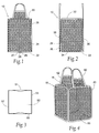
- FIG. 1 is a front plan view of the collapsible structure.
- FIG. 2 is a side plan view of the collapsible structure.
- FIG. 3 is a top plan view of the collapsible structure.
- FIG. 4 is a perspective view of the collapsible structure.
- FIG. 5 is a front plan view of the preferred embodiment of the collapsible structure.
- FIG. 6A is a side plan view of the collapsible structure.
- FIG. 6B is a partially cut-away view from FIG. 6A showing the frame member 22 .
- FIG. 7 is a top plan view of the collapsible structure.
- FIG. 8 is a perspective view of the collapsible structure.
- FIGS. 9-12 depict four alternative embodiments of the collapsible structure, namely showing different handle configurations.
- FIG. 13 is a perspective view of the collapsible structure including a storage pouch.
- FIG. 14 is a front plan view of a fifth embodiment of the collapsible structure, namely a two-compartment structure.
- FIG. 15 is a side plan view of a fifth embodiment of the collapsible structure.
- FIG. 16 is a top plan view of a fifth embodiment of the collapsible structure.
- FIG. 17 is a perspective view of a fifth embodiment of the collapsible structure.
- FIG. 18 is a front plan view of a sixth embodiment of the collapsible structure, namely a three-compartment structure.
- FIG. 19 is a side plan view of a sixth embodiment of a fifth embodiment of the collapsible structure.
- FIG. 20 is a top plan view of a sixth embodiment of the collapsible structure.
- FIG. 21 is a perspective view of a sixth embodiment of the collapsible structure.
- FIGS. 22A through 30 depict the preferred method of manufacturing the collapsible structure.
- FIGS. 31 through 36 depict the method of collapsing the collapsible structure.
- FIGS. 37 is a front plan view of a seventh embodiment of the collapsible structure, namely a structure having two frame members.
- FIG. 38 is a side plan view of the collapsible structure seen in FIG. 37 .
- FIG. 39 is a top plan view of the collapsible structure shown in FIG. 37 .
- FIG. 40 is a perspective view of the collapsible structure shown in FIG. 37 .
- FIG. 41 is a front plan view of another alternative embodiment of the collapsible, two-frame structure showing seam covers over the frame insertion points.
- FIG. 42 is a side plan view of the collapsible structure shown in FIG. 41 .
- FIG. 43 is a perspective view of the collapsible structure shown in FIG. 41 .
- FIG. 44 is a side plan view of a pair of side panels.
- FIG. 45 is a side plan view of the side panels with the edging partially attached.
- FIG. 46 is a side plan view of the side panels with the edging attached.
- FIG. 47 is a side plan view of the side panels and edging with the frame member being partially inserted.
- FIG. 48 is a side plan view of the side panels and edging with the frame member completely around one side panel and partially inserted around the other side panel.
- FIG. 49 is a side plan view of the side panels and edging with the frame member ends connected.
- FIG. 50 is a perspective view of two side panel pairs with the panels inverted to show placement of the floor panel 50 .
- FIG. 51 is an inverted perspective view of two side panel pairs, attached to one another and with the floor panel in place.
- FIG. 51 b is an inverted perspective view of the collapsible structure shown in FIG. 51, but including an optional storage pouch 70 .
- FIG. 52 is an enlarged view of the area 52 shown in FIG. 49, and showing the helical spring section of the frame member.
- FIG. 53 a is a view of the helical section of the frame member.
- FIG. 53 b is a cross sectional view of the frame member.
- FIG. 54 a is a view of the helical section of an alternative frame member.
- FIG. 54 b is a cross sectional view of the alternative frame member.
- FIG. 55 is a cross sectional view taken along lines 55 — 55 of FIG. 46 and showing the frame member in the edging.
- FIG. 56 is a side plan view of four contiguous side panels.
- FIG. 57 is a side plan view of the four contiguous side panels seen in FIG. 56, but with the edging attached.
- FIG. 58 is a side plan view of the four contiguous side panels seen in FIG. 57, with a frame member completely around two side panels and a second frame member partially inserted around the two remaining side panels.
- FIG. 59 is a perspective view of the four contiguous side panels seen in FIG. 58, but in inverted position to show placement of the floor panel 50 .
- FIG. 60 is an inverted perspective view of four contiguous side panels with free ends attached to one another and the floor panel in place.
- FIG. 60 a is an inverted perspective view of the collapsible structure shown in FIG. 60, but including an optional storage pouch 70 .
- FIG. 61 is a view showing the position of two frames around a four panel collapsible structure.
- FIGS. 62-67 depict the method of collapsing the collapsible structure, but using a flexible band to hold the collapsed bag in collapsed state.
- FIGS. 1 through 4 The present invention, a collapsible structure 10 , is illustrated in FIGS. 1 through 4.
- the structure 10 comprises four rectangular side panels 20 , a floor panel 50 , and two handles 60 and 62 .
- the side and floor panels 20 and 50 are connected to one another to form a substantially rectangular structure having an open top 16 .
- each side panel 20 further comprises a frame 22 , a web 24 , and an edging 26 .
- the frame 22 is flexible, preferably formed from a sufficiently stiff yet resilient material such as spring steel wire or plastic, and is contained within the channel or pocket 25 formed by the edging 26 (best seen in FIGS. 6 b and 24 b ).
- the frame 22 forms a continuous loop.
- the frame 22 has a rectangular cross-section, but a material with a different geometric cross-section can be used.
- the web 24 is a flexible foldable material, such as nylon cloth or nylon mesh, but can be any suitably flexible material.
- the nylon, or other flexible material may be solid or perforated.
- the perimeter of the web 24 is stitched to the edging 26 such that the edging 26 forms a pocket 25 about the periphery of the web 24 .
- the edging 26 is a foldable, but stretch-resistant material capable of housing the frame 22 within its pocket 25 .
- the edging 26 has two ends 27 and 29 .
- a seam cover 28 also made out of a foldable stretch-resistant material, may be provided to cover the ends 27 and 29 of the edging 26 , thereby protecting the frame 22 from escaping out of the edging 26 . As shown in FIG. 1, the seam cover 28 is also stitched to the web 24 .
- the floor panel 50 is also a foldable web of material and has a generally rectangular shape.
- the floor panel 50 has four corner sections 52 , 54 , 56 , 58 and is attached to four substantially perpendicular sides 51 , 53 , 55 , 57 of each side panel 20 .
- the floor panel 50 provides means for holding the garments or other objects (not shown) within the structure 10 and for supporting the structure 10 in its expanded state.
- FIGS. 5-8 one embodiment of the collapsible structure 10 is shown.
- This embodiment includes side panel separators 40 located between each side panel 20 .
- the side panel separators 40 are not required to practice the present invention.
- the side panel separators 40 are shown to be substantially longitudinal, each including an end 42 attached preferably by means of stitching to one of the corner sections 52 , 54 , 56 , 58 of the floor panel 50 .
- the other end 44 of each separator 40 corresponds to the open top 16 of the structure 10 .
- the side panel separators 40 are preferably formed from a stretch-resistant material similar to the material used for the seam covers 28 or the edging 26 .
- each rectangularly-shaped side panel 20 includes a top side 32 corresponding to the open top 16 of the structure 10 , a floor side 34 attached to one of the sides 51 , 53 , 55 , 57 of the floor panel 50 , and two lateral sides 36 and 38 .
- each lateral side 36 and 38 is attached to a side panel separator 40 adjacent to the side panel 20 .
- the handles 60 and 62 have both ends connected to the top side 32 of two opposing side panels 20 .
- the handles 60 and 62 are formed from a stretch-resistant material having a mesh web that extends between a portion of each strap side.
- the handles for the present invention are not limited to the particular type shown in FIGS. 4 and 8.
- FIGS. 9 through 12 illustrating different handle members.
- the handle members 60 and 62 are straps stitched to opposite side panels.
- FIG. 10 depicts an alternative embodiment wherein the handle members 60 and 62 are apertures or openings formed in the webs 24 of two opposite side panels 20 .
- one handle member 60 is shown as a strap coupled to diagonally opposed side seam separators 40 .
- the handles 60 and 62 are preferably stitched directly to the webs 24 of two opposite side panels 20 .
- an optional storage pouch 70 may be formed from a foldable material, such as nylon mesh, and stitched to the side 32 of one of the side panels 20 .
- the storage pouch 70 is dimensioned to accommodate the structure 10 in its collapsed state as later described.
- stitching is presented as the preferred means for attaching or connecting the elements of the structure 10 and permitting relatively convenient folding of the structure 10 , it is to be understood that other methods of attachment can be used in this invention. Such other methods may include heat sealing, gluing and the like. Accordingly, construction of the collapsible structure should not be limited to stitching alone.
- FIGS. 14 through 17 depict an alternative embodiment of the collapsible structure 12 .
- the structure 12 further includes a divider panel 80 .
- Divider panel 80 is connected to opposite side seam separators 40 thereby dividing the interior of the structure 12 into two separate chambers.
- FIGS. 18 to 21 show a second alternative embodiment of the collapsible structure 14 .
- the structure 14 comprises six side panels 20 and two divider panels 80 and 82 .
- the divider panels 80 and 82 are arranged substantially parallel to one another.
- Each divider panel 80 and 82 is made out of a foldable material, such as nylon mesh, and has two sides 86 and 88 stitched to webs 24 of two opposite side panels 20 .
- the divider panels 80 and 82 separate the interior of the structure 14 into three separate compartments for improved sorting and storage of objects.
- FIGS. 22 to 30 show various stages in the manufacturing process of the preferred embodiment of collapsible structure 10 .
- the step of stitching the handle 60 to the top side 32 of two (2) of the webs 24 is shown. Specifically, the stitching is shown at 90 .
- a seam cover 28 is partially stitched to side 21 of each of the four (4) webs 24 .
- the seam cover 28 is placed and sewn opposite to the handle 60 or 62 .
- Each seam cover 28 is preferably placed in the middle of the side 21 and includes a flap or unstitched portion, but it is to be understood that it could be placed anywhere on any side of each of the webs 24 .
- the edging 26 is then folded in a channel-like fashion around the periphery of the web 24 and stitched to the web 24 , surrounding the perimeter of the web 24 .
- the stitching is shown at 30 .
- each structure 10 requires four (4) webs 20 .
- the two (2) sides including the web 24 , edging 26 and seam cover 28 are shown in FIG. 24 a and the two (2) sides including the handle 60 , web 24 , edging 26 and seam cover 28 are shown in FIG. 25 . Stitching of each edging 26 starts and ends at the seam cover 28 , thereby leaving a small space between ends 27 and 29 of each edging 26 .
- the next step involves stitching each corner section 52 , 54 , 56 , 58 of the floor panel 50 to the end 42 of each side panel separator 40 .
- the stitching is shown at 46 .
- FIGS. 27 and 28 the step of attaching each of the four side panels 20 by means of stitching to the floor panel 50 and the side panel separators 40 is shown.
- the two (2) side panels 20 containing the handles 60 and 62 should be positioned opposite each other with the handles 60 and 62 facing inwardly toward each other.
- the floor side 34 of each of the side panels 20 is stitched to one of the sides 51 , 53 , 55 , 57 of the floor panel 50 as shown in FIG. 23 . Still referring to FIG.
- next the lateral sides 36 of each of the side panels 20 is stitched to the corresponding adjacent side panel separator 40 .
- the second lateral side 38 of another side panel separator 40 is stitched to the other side.
- the resulting enclosure 92 is shown in FIG. 29 .
- the structure 10 may be constructed without the side panel separators 40 .
- the two (2) side panels 20 containing the handles 60 and 62 are positioned opposite each other with their handles 60 and 62 facing inwardly toward each other.
- the floor side 34 of each of the side panels 20 is stitched to one of the sides 51 , 53 , 55 , 57 of the floor panel 50 .
- the lateral sides 36 , 38 of each of the side panels 20 are stitched to an adjacent side panel 20 thus forming the structure 10 having an open top 16 .
- the final steps of the manufacturing process of the present invention involve inserting the frame 22 in one of the open ends 27 or 29 of each of the edgings 26 as shown in FIG. 30 .
- the frame 22 is passed through the edging 26 and around the periphery of each of the side panels 20 .
- the ends of the frame 22 are joined together such that the frame 22 forms a continuous loop.
- the frame ends are connected by inserting each end into a butt connector and crimping the connector.
- the unstitched portion of each seam cover 28 is stitched to side 21 of each web 24 and over the ends 27 and 29 of each edging 26 , thereby protecting the frame 22 from escaping the edgings 26 .
- FIGS. 31 to 36 show various steps for collapsing the structure 10 .
- the first step requires grasping opposite sides of the structure 10 and biasing one toward the other until all side panels 20 are adjacent and overlay each other.
- the next step includes inserting the handle members 60 and 62 and the floor panel 50 in between any two of the adjacent overlaying side panels 20 is shown in FIG. 32 . It is important to make sure that the storage pouch 70 remains outside of the collapsed side panels 20 .
- the resulting partially collapsed structure 10 is a stack of four side panels 20 .
- FIG. 33 and 34 show the next step of rotating two opposite corners 101 and 103 of the partially collapsed structure 10 in opposite directions while biasing the corners 101 , 103 toward each other.
- the structure 10 will first twist and then will rotate to form three overlaying circular loops 150 situated adjacently as shown in FIG. 35 .
- the final step, shown in FIG. 36, is the insertion of the collapsed structure 10 into the storage pouch 70 .
- the frame members 22 When the collapsed structure 10 is removed from the storage pouch 70 , the frame members 22 will bias the structure 10 into its fully expanded state. Again, the fully expanded state of the embodiment is that shown in FIG. 4 .
- the structure 100 includes four side panels 20 and a floor panel 50 .
- the side panels 20 and floor panel 50 are connected to one another to form the structure 100 having an open top 16 .
- Two side panels 20 are connected to form a pair 84 of side panels 20 .
- Two pair 84 of side panels 20 are preferably used to form the structure 100 .
- the preferred embodiment in these views includes a single modified frame 22 ′ for each pair 84 of side panels 20 .
- Each side panel 20 further comprises a web 24 and an edging 26 .
- the web 24 is a flexible foldable material, such as nylon cloth or nylon mesh, but any suitable material may be used.
- the material may be solid or perforated, as desired.
- the frame 22 ′ is flexible, preferably formed from a sufficiently stiff yet resilient material such as spring steel wire or plastic, and similarly to the previously described embodiments, is contained within the channel or pocket 25 (seen in FIG. 55) formed by the edging 26 .
- the edging 26 is a foldable, but stretch-resistant material capable of housing the modified frame 22 ′ within its pocket 25 .
- the edging 26 has two ends, 27 and 29 .
- the frames 22 ′ are each formed in a “figure eight” configuration as will be discussed in more detail. As shown in FIG. 53 b , the frame 22 ′ has a rectangular cross-section, but a material with a different geometric cross-section may be used. For purposes of example only, an alternative cross-section, seen as circular, is shown in FIG. 54 b.
- FIGS. 41-43 illustrate another embodiment of the two frame structure 100 .
- a seam cover 28 is stitched to each web 24 and over the open ends 27 and 29 of each edging 26 , thereby protecting the frame 22 ′ from escaping the edging 26 .
- Each seam cover 28 includes a flap or unstitched portion, and it is to be understood that it could be placed anywhere on any side of each of the webs 24 , depending on the insertion point of the frame 22 ′ defined by the open ends 27 and 29 .
- FIGS. 44-49 illustrate the various stages in the manufacturing process of the two-frame structure 100 shown in FIGS. 37-40.
- first pair 84 of contiguous side panels 20 two integrally formed, contiguous webs 24 seen in FIG. 44, are provided.
- Edging material 26 is then attached to the web 24 perimeter and a portion of the contiguous border 72 , as shown in FIG. 45 .
- the edging 26 is folded in a channel-like fashion around the periphery of the web 24 and stitched to the web 24 with stitching 30 .
- the folded and stitched edging 26 forms a pocket 25 (seen best in FIG. 55) around the periphery of the web 24 . Stitching of each edging 26 starts and ends at the open ends 27 and 29 , preferably located at the contiguous border 72 .
- the next steps of the manufacturing process of the present invention involve inserting the frame 22 ′ in one of the open ends 27 or 29 of the edging 26 as shown in FIG. 47 .
- the frame 22 ′ is passed through the edging 26 and around the periphery of each of the side panels 20 .
- As the frame 20 ′ completes its circuit around the first side panel 20 it crosses over itself at open end 27 , 29 to form a “figure eight” as it enters the edging 26 of the second panel 20 .
- the ends of the frame 22 ′ are joined together at a helical portion 68 such that the frame 22 ′ forms a continuous loop.
- the frame ends are connected by inserting each end into a butt connector 64 and crimping the connector 64 (see in particular FIG. 52 ).
- the steps shown in FIG. 44-49 are completed a second time to form a second pair 84 of contiguous side panels 20 .
- the first and second pair 84 of contiguous side panels 20 are positioned to form the structure 100 .
- the floor panel 50 is attached to the floor side 34 of panels 20 , as shown particularly in FIG. 50, and the first and second pair 84 of contiguous side panels 20 are attached to one another along the edging 26 of lateral sides 36 , 38 of panels 20 .
- an optional storage pouch 70 may be formed from a foldable material, such as nylon mesh, and stitched to the top side 32 of one of the panels 20 .
- the storage pouch 70 is dimensioned to accommodate the structure 100 in its collapsed state, as will be described.
- the frame 22 ′ includes a helical portion 68 , 68 ′.
- the helical portion 68 has a relatively flat cross section whereas the portion 68 ′may be formed with a circular cross section.
- the helical portions 68 , 68 ′ provide a means for expansion and contraction of the frame 22 ′ which allows facile folding and unfolding of each individual pair 84 of panels 20 , as will be later described.
- FIGS. 56-60 b illustrate an alternative manufacturing process of the two-frame structure 100 .
- four integrally formed, contiguous webs 24 are provided.
- edging material 26 is then attached to the web 24 perimeter and a portion of the contiguous border 72 , leaving insertion areas 74 defined by open ends 27 and 29 .
- the edging 26 is folded in a channel-like fashion around the periphery of the web 24 and stitched to the web 24 with stitching 30 .
- the folded and stitched edging 26 forms a pocket 25 . Stitching of each edging 26 starts and ends at open ends 27 and 29 .
- the next step in the alternative manufacturing process involves inserting a frame 22 ′ at each insertion area 74 , in an open end 27 or 29 of the edging 26 .
- each frame 20 ′ of the embodiment shown in FIG. 58 completes its circuit around a panel 20 , crosses over itself at insertion area 74 , and enters a second panel 20 in open end 27 or 29 .
- the ends of the frame 22 ′ are joined together to form a continues loop.
- a crimped butt connector 64 retains the ends.
- the alternative method of manufacture is completed as seen in FIGS. 59 and 60 in a manner similar to that described with reference to FIGS. 50 and 51.
- the method may optionally include a storage pouch 70 , as seen in FIG. 60 b.
- the two frame structure 100 of FIGS. 37-61 may, from the expanded state, be folded into a collapsed state for storage and transportation.
- FIGS. 31 to 36 show various steps for collapsing the structure 10 , and the two frame structure 100 is similarly collapsed, as shown in FIGS. 62-67.
- the first step requires grasping opposite sides of the structure 100 and biasing one toward the other until all side panels 20 are adjacent and overlay each other.
- the next step includes inserting the handle members 60 and 62 , if provided, and the floor panel 50 in between any two of the adjacent overlaying side panels 20 is shown in FIG. 63 .
- the resulting partially collapsed structure 100 is a stack of four side panels 20 .
- FIGS. 64 and 65 show the next step of rotating two opposite corners 101 and 103 of the partially collapsed structure 100 in opposite directions while biasing the corners 101 , 103 toward each other.
- the structure 100 will first twist and then will rotate to form three overlaying circular loops 150 situated adjacently as shown in FIG. 66 .
- the final step, shown with reference to structure 10 in FIG. 36, is the insertion of the collapsed structure 10 , 100 into the storage pouch 70 , if provided.
- the frame members 22 will bias the structure 100 into its fully expanded state.
- FIG. 67 An alternative folding step may be seen in FIG. 67 wherein the two frame structure 100 may be finally secured in the collapsed state by way of an elastic flexible band 66 .
Abstract
A collapsible structure having a plurality of side panels and a floor panel forming an enclosure having an open top. Each side panel comprises a web of material, and an edging material. The collapsible structure includes at least two flexible continuous loop frames which are substantially enveloped by the edging. The edging coupled to the periphery of the web. One or more handles may be attached to the structure or formed within one or more of the side panels. A method of making and collapsing the structure is also disclosed.
Description
This is a continuation-in-part patent application of U.S. patent application Ser. No. 09/393,956 filed on Sep. 10, 1999 now abandoned, which is a continuation-in-part of U.S. patent parent application Ser. No. 09/108,521 filed on Jul. 1, 1998 that has since issued to U.S. Pat. No. 5,971,188; both the pending application and the issued patent are commonly owned by the assignee hereof. The present invention relates generally to collapsible structures and specifically to a collapsible container and a method of making and using such a structure for convenient storage and transportation of items.
A typical household often encounters the need for temporary storage of garments prior to washing or cleaning. Regardless of the place where laundry or cleaning is done, either at home or in a commercial setting, soiled garments need to be sorted, stored, and eventually transported to a designated place. The present invention can be utilized for garment sorting, storage and transportation. The present invention can also be utilized as an organizer for various objects. For example, the present invention may be used to organize objects normally found in the trunk of a car. Alternatively, the present invention can also be used for other purposes, such as the storage or transportation of toys or other objects. Further yet, the present invention could be used as a child's play structure or pet den structure. Accordingly, its use is multipurpose as both a container and structure.
Numerous devices are known in the art to provide effective storage of soiled garments, for example laundry baskets, conventional hampers, or clothing bags. For example, U.S. Pat. No. 2,625,973 to Weldon et al. teaches a laundry hamper comprising a rectangular frame having upper and lower portions that telescope within one another in a detachable manner. The lower portion includes a base frame, while the upper portion comprises a top frame. A cover is secured by a hinge to the top frame and an outer bag surrounds the rectangular frame. A plurality of small inner bags are provided within the outer bag. U.S. Pat No. 1,581,888 to Thomas discloses a collapsible receptacle comprising two rectangular wire frames, hingedly secured together, means for holding the frames to form a triangularly shaped structure, and a fabric portion covering the frames and providing an enclosure.
However, all these prior art devices are voluminous in their expanded state, are uneasy to fold or collapse, are still relatively voluminous in their collapsed state, and are difficult to manipulate. The present invention solves the above-mentioned shortcomings and provides a convenient, easy to manipulate, and ergonomic means for storing or transporting garments or other objects.
Other devices are known in the art to be collapsible structures. For example, U.S. Pat. No. 5,560,385 to Zheng teaches a collapsible play structure. This device forms a large cubicle that children can crawl through. However, each cube of the Zheng device utilizes three (3) frame members, preferably four members, to achieve structural integrity. The present invention may be practiced with as few as two frame members.
The present invention relates generally to a collapsible structure and specifically to a collapsible structure for storing articles or forming a child's toy and method of making and using the same.
According to the present invention, the foregoing and other advantages are obtained by providing a collapsible structure comprising a plurality of side panels and a floor panel forming an enclosure having an open top. In the preferred embodiment, each side panel comprises a flexible continuous loop frame, a web of material, and an edging material. The edging envelops the frame and is coupled to the periphery of the web. The floor panel is attached to the bottom side of each side panel thus forming the structure.
In an alternative embodiment, each side panel is attached to a side panel separator, which in turn is connected to the next adjacent side panel. The floor panel is attached to both the bottom side of each side panel and to the side panel separators, thus providing means for holding articles within the structure and for supporting the structure in its expanded state.
In another alternative embodiment, a single frame member forms the frame structure for two side panels. Each side panel comprises a web of material and an edging material. The edging material is attached to portions of the web. The edging partially envelops the frame and is coupled to predetermined portions of the periphery of the web. The floor panel is attached to the bottom side of each side panel, thus forming the structure.
In accordance with an aspect of the invention, at least one handle member is coupled to opposite side panels at the open top of the structure. Alternatively, the handle may be coupled to only one side panel or may be an aperture formed within one or more of the side panels.
In accordance with another aspect of the invention, an optional storage pouch may be coupled to one of the side panels at the open top of the structure. The present invention is easily collapsed into a compact state and the pouch allows storage of the structure in its collapsed, compact state.
In another alternative embodiment, the collapsible structure further comprises a divider panel, the divided panel being attached to diagonally opposite edgings of the side panels. In yet another alternative embodiment, the collapsible structure further comprises at least two divider panels, preferably arranged substantially parallel to each other and being coupled to opposite side panels to create at least three separate compartments within the structure.
A preferred method of manufacturing the collapsible structure includes the steps of attaching each handle member to a side of two opposite webs. The edging is next coupled to each web such that the edging surrounds the perimeter of the web and forms a channel or pocket through which the frame will later be inserted. After the requisite number of side panels has been formed, each side of the floor panel is attached to the bottom side of each side panel. Next, a side of each side panel is connected with a side of an adjacent side panel. The frame for each side panel is inserted through the channel formed by each edging. The ends of each frame member are connected, preferably using a crimped butt connector, to give the collapsible structure its ability to freely stand in a rigid, expanded, upright state.
An alternative method of manufacturing the collapsible structure includes the steps of supplying two attached webs of material. Next, edging is coupled to each web such that the edging substantially surrounds the perimeter of each web and forms a channel or pocket through which the frame will later be inserted. An opening in the webbing is left along the respective sides where the two webs are contiguous. A two-web side panel is thus formed. After a pair of two-web side panels have been formed, a single frame is inserted through the channel formed by the edging of each two-web side panel. Each frame first is threaded through the edging surrounding one web and then is threaded through the edging surrounding the second, contiguous web. The ends of each frame member are connected, preferably using a crimped butt connector, in a “figure eight” configuration to give the collapsible structure its ability to freely stand in a rigid, expanded, upright state. The second two-web side panel is completed by the same steps. The pair of two-web side panels are connected together and a floor panel is attached along the lower edge of each side panel.
Yet another alternative method of manufacturing the collapsible structure includes the steps of attaching each handle member to a side of two opposite webs. Coupling the edging to each web such that the edging surrounds the perimeter of the web and forms a channel or pocket through which the frame will later be inserted. After the requisite number of side panels has been formed, each corner of the floor panel is attached to one end of each side panel separator. Next each side panel is connected with one side of the floor panel and with two adjacent side panel separators. The frame for each side panel is inserted through the channel formed by each edging. The ends of each frame member are connected, preferably using a crimped butt connector, to give the collapsible structure its ability to freely stand in a rigid, expanded, upright state.
From the expanded state, the structure can be folded and collapsed for storage or transportation. The preferred steps of collapsing the structure include grasping opposite corners of the floor panel and biasing one corner toward the other until all side panels are adjacent and overlay each other. The structure is now partially collapsed but each side panel is still in an expanded state. Next, the optional handle members and the floor panel are inserted in between any two of the adjacent overlaying side panels. By rotating two opposite corners of the flattened, overlaying side panels in opposite directions while biasing the two corners toward each other, the structure will form three overlaying circular loops folded adjacently. Finally, the three overlaying loops may be placed into an optional storage pouch. The pouch prevents the structure from springing back into its fully expanded condition. Alternatively, the three overlaying loops may be maintained in the collapsed state by way of an elastic band or other retaining device.
FIG. 1 is a front plan view of the collapsible structure.
FIG. 2 is a side plan view of the collapsible structure.
FIG. 3 is a top plan view of the collapsible structure.
FIG. 4 is a perspective view of the collapsible structure.
FIG. 5 is a front plan view of the preferred embodiment of the collapsible structure.
FIG. 6A is a side plan view of the collapsible structure.
FIG. 6B is a partially cut-away view from FIG. 6A showing the frame member 22.
FIG. 7 is a top plan view of the collapsible structure.
FIG. 8 is a perspective view of the collapsible structure.
FIGS. 9-12 depict four alternative embodiments of the collapsible structure, namely showing different handle configurations.
FIG. 13 is a perspective view of the collapsible structure including a storage pouch.
FIG. 14 is a front plan view of a fifth embodiment of the collapsible structure, namely a two-compartment structure.
FIG. 15 is a side plan view of a fifth embodiment of the collapsible structure.
FIG. 16 is a top plan view of a fifth embodiment of the collapsible structure.
FIG. 17 is a perspective view of a fifth embodiment of the collapsible structure.
FIG. 18 is a front plan view of a sixth embodiment of the collapsible structure, namely a three-compartment structure.
FIG. 19 is a side plan view of a sixth embodiment of a fifth embodiment of the collapsible structure.
FIG. 20 is a top plan view of a sixth embodiment of the collapsible structure.
FIG. 21 is a perspective view of a sixth embodiment of the collapsible structure.
FIGS. 22A through 30 depict the preferred method of manufacturing the collapsible structure.
FIGS. 31 through 36 depict the method of collapsing the collapsible structure.
FIGS. 37 is a front plan view of a seventh embodiment of the collapsible structure, namely a structure having two frame members.
FIG. 38 is a side plan view of the collapsible structure seen in FIG. 37.
FIG. 39 is a top plan view of the collapsible structure shown in FIG. 37.
FIG. 40 is a perspective view of the collapsible structure shown in FIG. 37.
FIG. 41 is a front plan view of another alternative embodiment of the collapsible, two-frame structure showing seam covers over the frame insertion points.
FIG. 42 is a side plan view of the collapsible structure shown in FIG. 41.
FIG. 43 is a perspective view of the collapsible structure shown in FIG. 41.
FIG. 44 is a side plan view of a pair of side panels.
FIG. 45 is a side plan view of the side panels with the edging partially attached.
FIG. 46 is a side plan view of the side panels with the edging attached.
FIG. 47 is a side plan view of the side panels and edging with the frame member being partially inserted.
FIG. 48 is a side plan view of the side panels and edging with the frame member completely around one side panel and partially inserted around the other side panel.
FIG. 49 is a side plan view of the side panels and edging with the frame member ends connected.
FIG. 50 is a perspective view of two side panel pairs with the panels inverted to show placement of the floor panel 50.
FIG. 51 is an inverted perspective view of two side panel pairs, attached to one another and with the floor panel in place.
FIG. 51b is an inverted perspective view of the collapsible structure shown in FIG. 51, but including an optional storage pouch 70.
FIG. 52 is an enlarged view of the area 52 shown in FIG. 49, and showing the helical spring section of the frame member.
FIG. 53a is a view of the helical section of the frame member.
FIG. 53b is a cross sectional view of the frame member.
FIG. 54a is a view of the helical section of an alternative frame member.
FIG. 54b is a cross sectional view of the alternative frame member.
FIG. 55 is a cross sectional view taken along lines 55—55 of FIG. 46 and showing the frame member in the edging.
FIG. 56 is a side plan view of four contiguous side panels.
FIG. 57 is a side plan view of the four contiguous side panels seen in FIG. 56, but with the edging attached.
FIG. 58 is a side plan view of the four contiguous side panels seen in FIG. 57, with a frame member completely around two side panels and a second frame member partially inserted around the two remaining side panels.
FIG. 59 is a perspective view of the four contiguous side panels seen in FIG. 58, but in inverted position to show placement of the floor panel 50.
FIG. 60 is an inverted perspective view of four contiguous side panels with free ends attached to one another and the floor panel in place.
FIG. 60a is an inverted perspective view of the collapsible structure shown in FIG. 60, but including an optional storage pouch 70.
FIG. 61 is a view showing the position of two frames around a four panel collapsible structure.
FIGS. 62-67 depict the method of collapsing the collapsible structure, but using a flexible band to hold the collapsed bag in collapsed state.
Although the disclosure hereof is detailed and exact to enable those skilled in the art to practice the invention, the physical embodiments herein disclosed merely exemplify the invention which may be embodied in other specific structure. While the preferred embodiment has been described, the details may be changed without departing from the invention, which is defined by the claims.
The present invention, a collapsible structure 10, is illustrated in FIGS. 1 through 4.
As shown in FIG. 4, the structure 10 comprises four rectangular side panels 20, a floor panel 50, and two handles 60 and 62. The side and floor panels 20 and 50 are connected to one another to form a substantially rectangular structure having an open top 16.
Referring to FIGS. 1 and 2, each side panel 20 further comprises a frame 22, a web 24, and an edging 26. The frame 22 is flexible, preferably formed from a sufficiently stiff yet resilient material such as spring steel wire or plastic, and is contained within the channel or pocket 25 formed by the edging 26 (best seen in FIGS. 6b and 24 b). The frame 22 forms a continuous loop. Preferably, the frame 22 has a rectangular cross-section, but a material with a different geometric cross-section can be used. The web 24 is a flexible foldable material, such as nylon cloth or nylon mesh, but can be any suitably flexible material. The nylon, or other flexible material, may be solid or perforated. The perimeter of the web 24 is stitched to the edging 26 such that the edging 26 forms a pocket 25 about the periphery of the web 24. The edging 26 is a foldable, but stretch-resistant material capable of housing the frame 22 within its pocket 25. The edging 26 has two ends 27 and 29.
A seam cover 28, also made out of a foldable stretch-resistant material, may be provided to cover the ends 27 and 29 of the edging 26, thereby protecting the frame 22 from escaping out of the edging 26. As shown in FIG. 1, the seam cover 28 is also stitched to the web 24.
As shown in FIG. 3, the floor panel 50 is also a foldable web of material and has a generally rectangular shape. The floor panel 50 has four corner sections 52, 54, 56, 58 and is attached to four substantially perpendicular sides 51, 53, 55, 57 of each side panel 20. The floor panel 50 provides means for holding the garments or other objects (not shown) within the structure 10 and for supporting the structure 10 in its expanded state.
Referring now to FIGS. 5-8, one embodiment of the collapsible structure 10 is shown. This embodiment includes side panel separators 40 located between each side panel 20. However, it should be noted that the side panel separators 40 are not required to practice the present invention. The side panel separators 40 are shown to be substantially longitudinal, each including an end 42 attached preferably by means of stitching to one of the corner sections 52, 54, 56, 58 of the floor panel 50. The other end 44 of each separator 40 corresponds to the open top 16 of the structure 10. The side panel separators 40 are preferably formed from a stretch-resistant material similar to the material used for the seam covers 28 or the edging 26.
As shown in FIG. 6A, each rectangularly-shaped side panel 20 includes a top side 32 corresponding to the open top 16 of the structure 10, a floor side 34 attached to one of the sides 51, 53, 55, 57 of the floor panel 50, and two lateral sides 36 and 38. Referring just to FIG. 6A, each lateral side 36 and 38 is attached to a side panel separator 40 adjacent to the side panel 20.
As depicted in FIGS. 4 and 8, the handles 60 and 62 have both ends connected to the top side 32 of two opposing side panels 20. The handles 60 and 62 are formed from a stretch-resistant material having a mesh web that extends between a portion of each strap side. The handles for the present invention are not limited to the particular type shown in FIGS. 4 and 8. Several alternative embodiments are shown in FIGS. 9 through 12, illustrating different handle members. In FIG. 9, the handle members 60 and 62 are straps stitched to opposite side panels. FIG. 10 depicts an alternative embodiment wherein the handle members 60 and 62 are apertures or openings formed in the webs 24 of two opposite side panels 20. In FIG. 11, one handle member 60 is shown as a strap coupled to diagonally opposed side seam separators 40. In FIG. 12, the handles 60 and 62 are preferably stitched directly to the webs 24 of two opposite side panels 20.
As shown in FIG. 13, an optional storage pouch 70 may be formed from a foldable material, such as nylon mesh, and stitched to the side 32 of one of the side panels 20. The storage pouch 70 is dimensioned to accommodate the structure 10 in its collapsed state as later described.
Although stitching is presented as the preferred means for attaching or connecting the elements of the structure 10 and permitting relatively convenient folding of the structure 10, it is to be understood that other methods of attachment can be used in this invention. Such other methods may include heat sealing, gluing and the like. Accordingly, construction of the collapsible structure should not be limited to stitching alone.
FIGS. 14 through 17 depict an alternative embodiment of the collapsible structure 12. The structure 12 further includes a divider panel 80. Divider panel 80 is connected to opposite side seam separators 40 thereby dividing the interior of the structure 12 into two separate chambers.
FIGS. 18 to 21 show a second alternative embodiment of the collapsible structure 14. The structure 14 comprises six side panels 20 and two divider panels 80 and 82. The divider panels 80 and 82 are arranged substantially parallel to one another. Each divider panel 80 and 82 is made out of a foldable material, such as nylon mesh, and has two sides 86 and 88 stitched to webs 24 of two opposite side panels 20. The divider panels 80 and 82 separate the interior of the structure 14 into three separate compartments for improved sorting and storage of objects.
FIGS. 22 to 30 show various stages in the manufacturing process of the preferred embodiment of collapsible structure 10. Referring to FIGS. 22A and 22B, the step of stitching the handle 60 to the top side 32 of two (2) of the webs 24 is shown. Specifically, the stitching is shown at 90.
In FIG. 23, a seam cover 28 is partially stitched to side 21 of each of the four (4) webs 24. In the two (2) webs having handles 60 or 62, the seam cover 28 is placed and sewn opposite to the handle 60 or 62. Each seam cover 28 is preferably placed in the middle of the side 21 and includes a flap or unstitched portion, but it is to be understood that it could be placed anywhere on any side of each of the webs 24. Referring now to FIG. 24B, the edging 26 is then folded in a channel-like fashion around the periphery of the web 24 and stitched to the web 24, surrounding the perimeter of the web 24. The stitching is shown at 30. The stitched edging 26 forms a pocket 25 around the periphery of each web 24. In the preferred embodiment, each structure 10 requires four (4) webs 20. The two (2) sides including the web 24, edging 26 and seam cover 28 are shown in FIG. 24a and the two (2) sides including the handle 60, web 24, edging 26 and seam cover 28 are shown in FIG. 25. Stitching of each edging 26 starts and ends at the seam cover 28, thereby leaving a small space between ends 27 and 29 of each edging 26.
In FIGS. 26A and 26B, the next step involves stitching each corner section 52, 54, 56, 58 of the floor panel 50 to the end 42 of each side panel separator 40. The stitching is shown at 46. Now referring to FIGS. 27 and 28, the step of attaching each of the four side panels 20 by means of stitching to the floor panel 50 and the side panel separators 40 is shown. The two (2) side panels 20 containing the handles 60 and 62 should be positioned opposite each other with the handles 60 and 62 facing inwardly toward each other. First, the floor side 34 of each of the side panels 20 is stitched to one of the sides 51, 53, 55, 57 of the floor panel 50 as shown in FIG. 23. Still referring to FIG. 23, next the lateral sides 36 of each of the side panels 20 is stitched to the corresponding adjacent side panel separator 40. As shown in FIG. 28, once the first lateral side 36 of a side panel separator 40 is stitched on one side, the second lateral side 38 of another side panel separator 40 is stitched to the other side. The resulting enclosure 92 is shown in FIG. 29.
As discussed previously, the structure 10 may be constructed without the side panel separators 40. In constructing the embodiment without side panel separators 40, the two (2) side panels 20 containing the handles 60 and 62 are positioned opposite each other with their handles 60 and 62 facing inwardly toward each other. The floor side 34 of each of the side panels 20 is stitched to one of the sides 51, 53, 55, 57 of the floor panel 50. Next the lateral sides 36, 38 of each of the side panels 20 are stitched to an adjacent side panel 20 thus forming the structure 10 having an open top 16.
The final steps of the manufacturing process of the present invention involve inserting the frame 22 in one of the open ends 27 or 29 of each of the edgings 26 as shown in FIG. 30. The frame 22 is passed through the edging 26 and around the periphery of each of the side panels 20. The ends of the frame 22 are joined together such that the frame 22 forms a continuous loop. In the preferred embodiment, the frame ends are connected by inserting each end into a butt connector and crimping the connector. Finally, the unstitched portion of each seam cover 28 is stitched to side 21 of each web 24 and over the ends 27 and 29 of each edging 26, thereby protecting the frame 22 from escaping the edgings 26.
From the expanded state, the structure 10 may be folded into a collapsed state for storage and transportation. FIGS. 31 to 36 show various steps for collapsing the structure 10. Referring to FIG. 31, the first step requires grasping opposite sides of the structure 10 and biasing one toward the other until all side panels 20 are adjacent and overlay each other. The next step includes inserting the handle members 60 and 62 and the floor panel 50 in between any two of the adjacent overlaying side panels 20 is shown in FIG. 32. It is important to make sure that the storage pouch 70 remains outside of the collapsed side panels 20. In the preferred embodiment, the resulting partially collapsed structure 10 is a stack of four side panels 20. FIGS. 33 and 34 show the next step of rotating two opposite corners 101 and 103 of the partially collapsed structure 10 in opposite directions while biasing the corners 101, 103 toward each other. The structure 10 will first twist and then will rotate to form three overlaying circular loops 150 situated adjacently as shown in FIG. 35. The final step, shown in FIG. 36, is the insertion of the collapsed structure 10 into the storage pouch 70.
When the collapsed structure 10 is removed from the storage pouch 70, the frame members 22 will bias the structure 10 into its fully expanded state. Again, the fully expanded state of the embodiment is that shown in FIG. 4.
Referring now to FIGS. 37-40, the preferred embodiment of the collapsible structure is shown as reference numeral 100. The structure 100 includes four side panels 20 and a floor panel 50. The side panels 20 and floor panel 50 are connected to one another to form the structure 100 having an open top 16. Two side panels 20 are connected to form a pair 84 of side panels 20. Two pair 84 of side panels 20 are preferably used to form the structure 100. The preferred embodiment in these views includes a single modified frame 22′ for each pair 84 of side panels 20. Each side panel 20 further comprises a web 24 and an edging 26. As in the previous embodiments, the web 24 is a flexible foldable material, such as nylon cloth or nylon mesh, but any suitable material may be used. The material may be solid or perforated, as desired. The frame 22′ is flexible, preferably formed from a sufficiently stiff yet resilient material such as spring steel wire or plastic, and similarly to the previously described embodiments, is contained within the channel or pocket 25 (seen in FIG. 55) formed by the edging 26. The edging 26 is a foldable, but stretch-resistant material capable of housing the modified frame 22′ within its pocket 25. The edging 26 has two ends, 27 and 29. The frames 22′ are each formed in a “figure eight” configuration as will be discussed in more detail. As shown in FIG. 53b, the frame 22′ has a rectangular cross-section, but a material with a different geometric cross-section may be used. For purposes of example only, an alternative cross-section, seen as circular, is shown in FIG. 54b.
FIGS. 41-43 illustrate another embodiment of the two frame structure 100. In this embodiment, a seam cover 28 is stitched to each web 24 and over the open ends 27 and 29 of each edging 26, thereby protecting the frame 22′ from escaping the edging 26. Each seam cover 28 includes a flap or unstitched portion, and it is to be understood that it could be placed anywhere on any side of each of the webs 24, depending on the insertion point of the frame 22′ defined by the open ends 27 and 29.
FIGS. 44-49 illustrate the various stages in the manufacturing process of the two-frame structure 100 shown in FIGS. 37-40. To form the first pair 84 of contiguous side panels 20, two integrally formed, contiguous webs 24 seen in FIG. 44, are provided. Edging material 26 is then attached to the web 24 perimeter and a portion of the contiguous border 72, as shown in FIG. 45. The edging 26 is folded in a channel-like fashion around the periphery of the web 24 and stitched to the web 24 with stitching 30. The folded and stitched edging 26 forms a pocket 25 (seen best in FIG. 55) around the periphery of the web 24. Stitching of each edging 26 starts and ends at the open ends 27 and 29, preferably located at the contiguous border 72.
The next steps of the manufacturing process of the present invention involve inserting the frame 22′ in one of the open ends 27 or 29 of the edging 26 as shown in FIG. 47. The frame 22′ is passed through the edging 26 and around the periphery of each of the side panels 20. As the frame 20′ completes its circuit around the first side panel 20, it crosses over itself at open end 27, 29 to form a “figure eight” as it enters the edging 26 of the second panel 20. When the frame 22′ is completely inserted in the pocket 25 surrounding both panels 20, the ends of the frame 22′ are joined together at a helical portion 68 such that the frame 22′ forms a continuous loop. In the preferred embodiment, the frame ends are connected by inserting each end into a butt connector 64 and crimping the connector 64 (see in particular FIG. 52). The steps shown in FIG. 44-49 are completed a second time to form a second pair 84 of contiguous side panels 20. As illustrated in FIGS. 5051 b, the first and second pair 84 of contiguous side panels 20 are positioned to form the structure 100. The floor panel 50 is attached to the floor side 34 of panels 20, as shown particularly in FIG. 50, and the first and second pair 84 of contiguous side panels 20 are attached to one another along the edging 26 of lateral sides 36, 38 of panels 20. As shown in FIG. 51b, an optional storage pouch 70 may be formed from a foldable material, such as nylon mesh, and stitched to the top side 32 of one of the panels 20. The storage pouch 70 is dimensioned to accommodate the structure 100 in its collapsed state, as will be described.
As will be observed in FIGS. 52-54b, the frame 22′ includes a helical portion 68, 68′. The helical portion 68 has a relatively flat cross section whereas the portion 68′may be formed with a circular cross section. The helical portions 68, 68′ provide a means for expansion and contraction of the frame 22′ which allows facile folding and unfolding of each individual pair 84 of panels 20, as will be later described.
FIGS. 56-60b illustrate an alternative manufacturing process of the two-frame structure 100. Seen particularly in FIG. 56, four integrally formed, contiguous webs 24 are provided. As shown in FIG. 57, edging material 26 is then attached to the web 24 perimeter and a portion of the contiguous border 72, leaving insertion areas 74 defined by open ends 27 and 29. Similarly to the previous embodiments, the edging 26 is folded in a channel-like fashion around the periphery of the web 24 and stitched to the web 24 with stitching 30. As seen in FIG. 55, the folded and stitched edging 26 forms a pocket 25. Stitching of each edging 26 starts and ends at open ends 27 and 29.
The next step in the alternative manufacturing process involves inserting a frame 22′ at each insertion area 74, in an open end 27 or 29 of the edging 26. As described with reference to FIG. 46, each frame 20′ of the embodiment shown in FIG. 58 completes its circuit around a panel 20, crosses over itself at insertion area 74, and enters a second panel 20 in open end 27 or 29. After the frame 22′ is completely inserted in the pocket 25 surrounding two adjacent panels 20, the ends of the frame 22′ are joined together to form a continues loop. A crimped butt connector 64 retains the ends. The alternative method of manufacture is completed as seen in FIGS. 59 and 60 in a manner similar to that described with reference to FIGS. 50 and 51. The method may optionally include a storage pouch 70, as seen in FIG. 60b.
As discussed in reference to the primarily described embodiments shown in FIGS. 1-30, the two frame structure 100 of FIGS. 37-61 may, from the expanded state, be folded into a collapsed state for storage and transportation. FIGS. 31 to 36 show various steps for collapsing the structure 10, and the two frame structure 100 is similarly collapsed, as shown in FIGS. 62-67. Referring to FIG. 62, the first step requires grasping opposite sides of the structure 100 and biasing one toward the other until all side panels 20 are adjacent and overlay each other. The next step includes inserting the handle members 60 and 62, if provided, and the floor panel 50 in between any two of the adjacent overlaying side panels 20 is shown in FIG. 63. It is important to make sure that the storage pouch 70, if provided, remains outside of the collapsed side panels 20 (as shown in FIG. 33). The resulting partially collapsed structure 100 is a stack of four side panels 20. FIGS. 64 and 65 show the next step of rotating two opposite corners 101 and 103 of the partially collapsed structure 100 in opposite directions while biasing the corners 101, 103 toward each other. The structure 100 will first twist and then will rotate to form three overlaying circular loops 150 situated adjacently as shown in FIG. 66. The final step, shown with reference to structure 10 in FIG. 36, is the insertion of the collapsed structure 10, 100 into the storage pouch 70, if provided.
When the collapsed structure 100 is removed from the storage pouch 70, the frame members 22 will bias the structure 100 into its fully expanded state.
An alternative folding step may be seen in FIG. 67 wherein the two frame structure 100 may be finally secured in the collapsed state by way of an elastic flexible band 66.
The foregoing is considered as illustrative only of the principles of the invention. Furthermore, since numerous modifications and changes will readily occur to those skilled in the art, it is not desired to limit the invention to the exact construction and operation shown and described. While the preferred embodiment has been described, the details may be changed without departing from the invention, which is defined by the claims.
Claims (19)
1. A collapsible structure having an open top, said collapsible structure comprising:
a plurality of adjacent side panels, each of said side panels including a web having a perimeter, an edging attached to substantially the entire perimeter of the web and forming a peripheral pocket, and a single loop frame-positioned within the pockets of a selected pair of contiguous side panels;
each of said side panels having a bottom side, a top side and two lateral sides;
a floor panel having a plurality of sides, each of said floor panel sides being attached to at least one of said side panel bottom sides;
each of said lateral sides of each side panel being attached to the lateral side of an adjacent side panel.
2. The collapsible structure of claim 1 , wherein said single loop frame includes an intermediate cross-over portion to define a general figure eight configuration of said loop frame.
3. The collapsible structure of claim 2 , wherein said cross-over portion of said single loop frame includes at least one helical portion.
4. The collapsible structure of claim 3 , wherein said frame and said at least one helical portion has a rectangular cross section.
5. The collapsible structure of claim 3 wherein said frame and said at least one helical portion has a circular cross section.
6. The collapsible structure of claim 1 , further comprising at least one handle member, said handle member being secured to at least one of said panels.
7. The collapsible structure or claim 1 , further including a storage pouch, said storage pouch being coupled to one of said side panels near said open tip.
8. The collapsible structure of claim 1 , wherein said side panels are substantially rectangular.
9. The collapsible structure of claim 1 , wherein said plurality of side panels is four.
10. The collapsible structure of claim 1 , wherein said frame of each of said side panels is flexible.
11. The collapsible structure of claim 1 , wherein said plurality of side panels is an even number.
12. A collapsible structure having an open top, said structure comprising:
a plurality of side panels, each of said side panels including a web having a perimeter, an edging attached to the perimeter of the web and forming a pocket, and a continuous loop frame;
the frame being positioned within the edging pocket;
each of said side panels having a bottom side and at least two lateral sides;
a plurality of side panel separators, said side panel separators each having a first end, a second end, and two lateral sides;
a floor panel having a plurality of sides and a plurality of corner sections, each of said floor panel sides being attached to the bottom side of at least one of said side panels;
each corner section of said floor panel being coupled to the first end of one of said side panel separators; and
each of said lateral sides of each side panel separator being attached to a lateral side of a side panel.
13. The collapsible structure of claim 12 , further comprising at least one handle member, said handle member being secured to at least one of said side panels.
14. The collapsible structure of claim 12 , further comprising a seam cover attached to said side panels and substantially enveloping a predetermined portion of said edging.
15. The collapsible structure of claim 12 , further including a storage pouch, said storage pouch being coupled to one of said side panels near said open top.
16. The collapsible structure of claim 12 , wherein said side panels are substantially rectangular.
17. The collapsible structure of claim 12 , wherein said plurality of side panels is an even number.
18. The collapsible structure of claim 12 , wherein said web of each said side panels is flexible web of material.
19. The collapsible structure of claim 12 , wherein said frame of each of said side panels is flexible.
Priority Applications (6)
| Application Number | Priority Date | Filing Date | Title |
|---|---|---|---|
| US09/698,674 US6494335B1 (en) | 1998-07-01 | 2000-10-27 | Two frame collapsible structure and method of making and using same |
| US09/834,437 US20010020618A1 (en) | 1998-07-01 | 2001-04-13 | Two frame collapsible structure and method of making and using same |
| US10/413,925 US6948632B2 (en) | 1998-07-01 | 2003-04-15 | Collapsible structure |
| US11/063,091 US20050167428A1 (en) | 1998-07-01 | 2005-02-22 | Collapsible structure |
| US12/319,051 US20090114648A1 (en) | 1998-07-01 | 2008-12-31 | Collapsible structure |
| US12/456,830 US8127956B2 (en) | 1998-07-01 | 2009-06-23 | Collapsible structure |
Applications Claiming Priority (3)
| Application Number | Priority Date | Filing Date | Title |
|---|---|---|---|
| US09/108,521 US5971188A (en) | 1998-07-01 | 1998-07-01 | Collapsible container and method of making and using same |
| US39395699A | 1999-09-10 | 1999-09-10 | |
| US09/698,674 US6494335B1 (en) | 1998-07-01 | 2000-10-27 | Two frame collapsible structure and method of making and using same |
Related Parent Applications (1)
| Application Number | Title | Priority Date | Filing Date |
|---|---|---|---|
| US39395699A Continuation-In-Part | 1998-07-01 | 1999-09-10 |
Related Child Applications (1)
| Application Number | Title | Priority Date | Filing Date |
|---|---|---|---|
| US09/834,437 Continuation-In-Part US20010020618A1 (en) | 1998-07-01 | 2001-04-13 | Two frame collapsible structure and method of making and using same |
Publications (1)
| Publication Number | Publication Date |
|---|---|
| US6494335B1 true US6494335B1 (en) | 2002-12-17 |
Family
ID=46277089
Family Applications (1)
| Application Number | Title | Priority Date | Filing Date |
|---|---|---|---|
| US09/698,674 Expired - Fee Related US6494335B1 (en) | 1998-07-01 | 2000-10-27 | Two frame collapsible structure and method of making and using same |
Country Status (1)
| Country | Link |
|---|---|
| US (1) | US6494335B1 (en) |
Cited By (42)
| Publication number | Priority date | Publication date | Assignee | Title |
|---|---|---|---|---|
| US20030070703A1 (en) * | 1996-09-20 | 2003-04-17 | Yu Zheng | Collapsible storage devices |
| US20030188943A1 (en) * | 2002-04-08 | 2003-10-09 | Roberta Freedman | Combination travel and laundry bag |
| US20040149328A1 (en) * | 1999-07-08 | 2004-08-05 | Patent Category Corp. | Collapsible structures |
| US20040155419A1 (en) * | 2003-02-07 | 2004-08-12 | Larry Gardenour | Collapsible refuse collection apparatus |
| US20060011628A1 (en) * | 2004-07-15 | 2006-01-19 | Israel Guevara | Adjustable hamper |
| US20060081285A1 (en) * | 2004-09-27 | 2006-04-20 | Manuel Gomez | Bar-be-cue saver picnic dome |
| US20060283111A1 (en) * | 2005-06-03 | 2006-12-21 | Ayers Ronald L | Work cubicle cover |
| US20070119492A1 (en) * | 1991-09-24 | 2007-05-31 | Yu Zheng | Collapsible signage structures |
| US20080128306A1 (en) * | 2006-12-05 | 2008-06-05 | Tamara Bateman | Gift wrap caddy |
| US7392555B2 (en) * | 2003-08-27 | 2008-07-01 | Happy Camper, Inc. | Bed-tent |
| US20080190921A1 (en) * | 2007-02-08 | 2008-08-14 | The Evercare Company | Clothes hamper |
| US20080226205A1 (en) * | 2007-03-12 | 2008-09-18 | Sillik Francisco J | Self-Standing Bag |
| US20090008283A1 (en) * | 2007-07-05 | 2009-01-08 | Jared Hendricks | Telescoping Ornament Storage Systems and Devices |
| US20090184115A1 (en) * | 2008-01-23 | 2009-07-23 | Wen-Tsan Wang | Storage container using bamboo/straw curtains |
| US20100018968A1 (en) * | 2008-07-23 | 2010-01-28 | Azad Sabounjian | Handle for collapsible container |
| USD610352S1 (en) | 2003-04-11 | 2010-02-23 | Bajer Design & Marketing, Inc. | Collapsible structure |
| USD612117S1 (en) | 2008-09-03 | 2010-03-16 | Bajer Design & Marketing, Inc. | Collapsible structure |
| US7845507B2 (en) | 2008-03-05 | 2010-12-07 | Bajer Design & Marketing, Inc. | Collapsible container having discontinuous frame members |
| US20110174811A1 (en) * | 2010-01-19 | 2011-07-21 | Pro-Mart Industires, Inc. | Collapsible container |
| US8127956B2 (en) | 1998-07-01 | 2012-03-06 | Bajer Design & Marketing, Inc. | Collapsible structure |
| USD661900S1 (en) | 2010-02-22 | 2012-06-19 | Bajer Design & Marketing, Inc. | Collapsible structure |
| US20120222188A1 (en) * | 2008-05-06 | 2012-09-06 | Patent Category Corp. | Collapsible Costumes |
| US8272674B2 (en) * | 2010-09-22 | 2012-09-25 | Techcognic Llc | Seat partition and method for partitioning passengers in a vehicle |
| US8342226B2 (en) | 2010-09-23 | 2013-01-01 | Patent Category Corp. | Collapsible sunshade |
| US20130051711A1 (en) * | 2011-08-25 | 2013-02-28 | Soly Abrahan Cattan | Packing bag for laundering and drying of garments |
| USD680329S1 (en) | 2012-06-19 | 2013-04-23 | Bajer Design & Marketing, Inc. | Collapsible structure |
| US8534752B2 (en) | 2010-06-02 | 2013-09-17 | Steelcase Inc. | Reconfigurable table assemblies |
| US20130270131A1 (en) * | 2012-04-16 | 2013-10-17 | Jon-Yie Shieh | Collapsible laundry basket |
| US8667626B2 (en) | 2010-10-05 | 2014-03-11 | Patent Category Corp | Collapsible baby play station |
| USD725315S1 (en) * | 2013-07-19 | 2015-03-24 | Purina Animal Nutrition Llc | Feed container |
| US9485957B2 (en) | 2014-08-28 | 2016-11-08 | Sportpet Designs, Inc. | Pet kennel |
| US9648933B2 (en) | 2015-04-01 | 2017-05-16 | Abiboo Corp. | Multi-purpose modular travel and packaging bag |
| US9689110B2 (en) | 2014-10-09 | 2017-06-27 | William Yates Massey, Jr. | Collapsible multi-purpose structure |
| US9828721B2 (en) | 2014-12-12 | 2017-11-28 | Butler Home Products, Llc | Collapsible laundry hamper |
| US10010048B2 (en) | 2013-05-29 | 2018-07-03 | Sportpet Designs, Inc. | Collapsible kennel |
| US10010049B2 (en) | 2013-05-29 | 2018-07-03 | Sportpet Designs, Inc. | Collapsible kennel |
| US10039374B2 (en) | 2016-05-13 | 2018-08-07 | Steelcase Inc. | Multi-tiered workstation assembly |
| US10517392B2 (en) | 2016-05-13 | 2019-12-31 | Steelcase Inc. | Multi-tiered workstation assembly |
| US10681980B2 (en) | 2010-06-02 | 2020-06-16 | Steelcase Inc. | Frame type workstation configurations |
| USD894604S1 (en) * | 2020-05-14 | 2020-09-01 | Xiamen Xinghengxing Import & Export Co., Ltd. | Storage bag |
| US10863806B2 (en) * | 2019-04-23 | 2020-12-15 | The Better Shopping Bag Co. Inc. | Collapsibly erectable bag |
| US11434049B2 (en) * | 2013-08-17 | 2022-09-06 | Daniel Ager | Collapsible container |
Citations (261)
| Publication number | Priority date | Publication date | Assignee | Title |
|---|---|---|---|---|
| US177749A (en) | 1876-05-23 | Improvement in grain-bags | ||
| US216227A (en) | 1879-06-03 | Improvement in collapsible drinking-cups | ||
| US217362A (en) | 1879-07-08 | Improvement in grain-bag and fastening | ||
| US218277A (en) | 1879-08-05 | Improvement in seal-locks | ||
| US251325A (en) | 1881-12-20 | Filling-cup for morocco-manufacturers | ||
| US334340A (en) | 1886-01-12 | Machinist s jig | ||
| US338892A (en) | 1886-03-30 | Cotton-basket | ||
| US356301A (en) | 1887-01-18 | Willis h | ||
| US414622A (en) | 1889-11-05 | willtts | ||
| US481957A (en) | 1892-09-06 | Device for holding open grain and other sacks for filling same | ||
| US665942A (en) | 1900-06-09 | 1901-01-15 | Jasper Newton Tabler | Mail-pouch. |
| US929430A (en) | 1908-09-01 | 1909-07-27 | Bert Hill | Clothes-pin receptacle. |
| US945918A (en) | 1908-10-21 | 1910-01-11 | Joseph T Crawford | Metallic roofing for cars. |
| US975745A (en) | 1910-07-01 | 1910-11-15 | Robert A Bower | Head-envelop. |
| US1087702A (en) | 1913-06-25 | 1914-02-17 | Samuel R Van Patten | Flexible container. |
| US1135892A (en) | 1915-04-13 | Louis F Grosenbeck | Knockdown mail-container. | |
| US1144643A (en) | 1914-03-26 | 1915-06-29 | Henry O Elkins | Container. |
| US1155475A (en) | 1913-07-05 | 1915-10-05 | Thomas J Fay | Collapsible-frame parcel-sack. |
| US1167497A (en) | 1913-12-11 | 1916-01-11 | Fay C Hayes | Collapsible bucket. |
| US1180574A (en) | 1915-07-17 | 1916-04-25 | Michael Despot | Collapsible mail-bag. |
| US1181829A (en) | 1914-08-13 | 1916-05-02 | Anson E Bower | Hamper. |
| US1206618A (en) | 1915-12-16 | 1916-11-28 | Franklin J Thrasher | Parcel-post and merchandise protector. |
| US1251560A (en) | 1917-08-06 | 1918-01-01 | Theodore Myskow | Wire basket for boilers. |
| US1263294A (en) | 1916-10-26 | 1918-04-16 | Bayard E Taylor | Collapsible shipping-crate. |
| US1308268A (en) | 1919-07-01 | Planoorapii co | ||
| US1360844A (en) | 1920-07-02 | 1920-11-30 | George W Williams | Mouthpiece |
| US1394007A (en) | 1921-01-03 | 1921-10-18 | Hall Mary Lucy | Collapsible wardrobe |
| US1520532A (en) | 1921-09-14 | 1924-12-23 | Charles N Clark | Basket |
| US1538260A (en) | 1923-10-31 | 1925-05-19 | Street Benjamin Seymour | Tobacco-firing device |
| FR589062A (en) | 1924-11-06 | 1925-05-22 | Expandable | |
| US1581888A (en) | 1925-05-27 | 1926-04-20 | Thomas Arthur | Collapsible receptacle |
| US1583083A (en) | 1924-06-17 | 1926-05-04 | Macaraig Jose | Collapsible receptacle |
| US1640083A (en) | 1926-05-11 | 1927-08-23 | Ladd George Frank | Device for use in sorting and delivering mail |
| US1647679A (en) | 1925-04-20 | 1927-11-01 | Louise H Williams | Collapsible hatbox |
| US1691904A (en) | 1921-11-24 | 1928-11-13 | Helen C Gamble | Collapsible hat bag |
| US1703066A (en) | 1929-02-19 | Ftjbniture attachment | ||
| US1836297A (en) | 1930-06-19 | 1931-12-15 | Vienna Frank | Insert-container for garbage receptacles |
| US1979978A (en) | 1932-06-27 | 1934-11-06 | Martin Patrick Alphonsus | Hand bag and case |
| US1994235A (en) | 1934-03-23 | 1935-03-12 | Solomon Samuel | Brief case or the like |
| US1999424A (en) | 1933-02-16 | 1935-04-30 | Seitz Charles Henry | Traveling bag |
| US2009035A (en) | 1932-08-25 | 1935-07-23 | Anchor Duck Mills | Laundry bag |
| US2042888A (en) | 1935-05-27 | 1936-06-02 | Dennison Mfg Co | Pinning machine |
| US2057942A (en) | 1935-01-29 | 1936-10-20 | Fay Marc Aurele Alfred | Toy construction unit |
| US2071850A (en) | 1935-03-18 | 1937-02-23 | Elliot A Miller | Garment storage bag |
| US2115308A (en) | 1936-09-09 | 1938-04-26 | Roderick M Koch | Special receptacle |
| US2136761A (en) | 1936-04-09 | 1938-11-15 | Jack W Simmons | Collapsible package |
| US2182932A (en) | 1937-06-19 | 1939-12-12 | Percy P Sanford | Package |
| US2269574A (en) | 1940-01-12 | 1942-01-13 | Benenfeld Peter | Wired bag |
| US2280601A (en) | 1939-12-26 | 1942-04-21 | Judson R Otter | Container |
| US2295584A (en) | 1940-12-19 | 1942-09-15 | Larson Charles | Bag attachment |
| US2298786A (en) | 1940-01-29 | 1942-10-13 | Dubofsky Harry | Reinforcing seam for overnight, bathing, and other bags |
| US2361743A (en) | 1943-03-05 | 1944-10-31 | Glenn L Martin Co | Flexible cell support |
| US2544074A (en) | 1946-12-07 | 1951-03-06 | Columbus Coated Fabrics Corp | Collapsible frame for utility baskets |
| US2575893A (en) | 1949-11-14 | 1951-11-20 | Norman R Seaman | Collapsible heat-insulated container |
| US2600501A (en) | 1947-10-27 | 1952-06-17 | Higgs George William | Oxygen tent or like enclosure |
| US2625973A (en) | 1951-08-31 | 1953-01-20 | John J Weldon | Laundry hamper |
| US2639819A (en) | 1950-04-15 | 1953-05-26 | Phoenix Closet Accessories Inc | Knockdown shelving |
| US2664131A (en) | 1951-12-07 | 1953-12-29 | Benjamin G Miller | Collapsible bucket |
| US2710084A (en) | 1954-02-23 | 1955-06-07 | Irving L Braverman | Traveling bags |
| US2721099A (en) | 1952-11-20 | 1955-10-18 | Virgil R Rupp | Insecticidal unit |
| US2724537A (en) | 1952-03-13 | 1955-11-22 | Walter G S Fehr | Shipping container |
| US2746582A (en) | 1953-07-27 | 1956-05-22 | Atlantic Prod Corp | Luggage bags |
| US2767757A (en) | 1955-04-20 | 1956-10-23 | Herbert B Marder | Receptacle construction |
| US2778560A (en) | 1954-11-05 | 1957-01-22 | Edward J Pfeiffer | Collapsible box |
| US2780402A (en) | 1953-09-08 | 1957-02-05 | Hamper Tainer Co Inc | Diaper hamper with deodorizing means |
| US2833460A (en) | 1955-12-23 | 1958-05-06 | Michael A Votolato | Bag |
| US2879553A (en) | 1957-05-31 | 1959-03-31 | Richard T Keating | Toy igloo |
| US2958357A (en) | 1959-04-03 | 1960-11-01 | Vorgan Harry | Collapsible cover |
| US3014516A (en) | 1959-02-02 | 1961-12-26 | William F Mueller | Collapsible container |
| US3017117A (en) | 1960-12-27 | 1962-01-16 | Frank J Curran Co | Deodorant insert for toilet tissue |
| US3061396A (en) | 1960-05-02 | 1962-10-30 | Lester R Hock | Collapsible cabinet |
| US3126933A (en) | 1964-03-31 | Traveller s canine canteen | ||
| FR1380738A (en) | 1963-10-25 | 1964-12-04 | Jamet Andre | Advanced training in tents with kitchen |
| US3160307A (en) | 1962-07-13 | 1964-12-08 | Willard L Morrison | Insulated shipper container |
| US3233644A (en) | 1962-07-30 | 1966-02-08 | Gertrude Q Bono | Hamper |
| US3257077A (en) | 1964-04-13 | 1966-06-21 | Advance Chemical Company | Wick-type deodorizer and attachment means |
| US3260396A (en) | 1962-12-10 | 1966-07-12 | Stapling Machines Co | Stackable knockdown wirebound container |
| US3265284A (en) | 1964-05-13 | 1966-08-09 | Owens Illinois Glass Co | Bulk storage container |
| US3310089A (en) | 1965-10-04 | 1967-03-21 | Silverman Max | Hampers |
| US3354924A (en) | 1966-05-23 | 1967-11-28 | Owens Illinois Inc | Collapsible container |
| US3373925A (en) | 1965-08-12 | 1968-03-19 | Gatward Harry Frederick | Carrier bags and handles for attachment thereto |
| US3410328A (en) | 1964-10-05 | 1968-11-12 | Sasai Hideo | Delivery container for perishable foods |
| US3439865A (en) | 1964-12-17 | 1969-04-22 | Parker Pace Corp | Woven plastic bags |
| US3480059A (en) | 1967-10-19 | 1969-11-25 | Griffolyn Company | Collapsible receptacle for large quantities |
| US3502091A (en) | 1968-09-12 | 1970-03-24 | Wendel V Goltermann | Tent supporting frame |
| DE2015649A1 (en) | 1969-05-27 | 1971-02-18 | Löffler, Roland, χ 9000 Karl Marx-Stadt | Play equipment for children's play areas or the like composed of various components. |
| US3583748A (en) | 1969-09-09 | 1971-06-08 | Slings Inc | Laundry hopper |
| US3603367A (en) | 1969-07-23 | 1971-09-07 | Ironees Co | Collapsible hamper |
| US3661326A (en) | 1970-01-07 | 1972-05-09 | Milton A Wilson | Insecticide and repellant holder for attachment to garbage can lid |
| US3675667A (en) | 1970-09-25 | 1972-07-11 | Jack V Miller | Self-erecting tent |
| US3675981A (en) | 1969-01-28 | 1972-07-11 | Filip Birger Emanuel Mallander | Collapsible storage unit |
| US3696850A (en) | 1971-07-12 | 1972-10-10 | Julia R Rosenblum | Multiple unit hand luggage |
| US3709237A (en) | 1970-12-07 | 1973-01-09 | D Smith | Sportsmans blind |
| US3727786A (en) | 1972-02-22 | 1973-04-17 | A Fausel | Knock down hamper |
| US3732978A (en) | 1972-03-16 | 1973-05-15 | A Reader | Method and apparatus for sorting and distributing mail |
| US3733758A (en) | 1970-05-02 | 1973-05-22 | Messerschmitt Boelkow Blohm | Mechanism for unfolding accordion-like folded structural elements |
| US3796342A (en) | 1972-06-05 | 1974-03-12 | Pinckney Molded Plastics | Collapsible container |
| US3799384A (en) | 1972-02-28 | 1974-03-26 | C Hurkamp | Collapsible shipping container |
| US3807421A (en) | 1972-03-13 | 1974-04-30 | David Geiger Horst Berger P C | Prestressed membrane structure |
| US3834528A (en) | 1971-03-05 | 1974-09-10 | British Visqueen Ltd | Carrier-bags |
| US3843222A (en) | 1972-11-07 | 1974-10-22 | Cosco Inc | Clothes hamper |
| US3868155A (en) | 1973-12-13 | 1975-02-25 | Albert E Cherubini | Foldable and storable enclosure |
| US3880459A (en) | 1973-02-22 | 1975-04-29 | Robert A Kelley | Tent enclosure |
| US3883026A (en) | 1973-04-23 | 1975-05-13 | John C Selz | Collapsible wall container |
| US3893649A (en) | 1971-08-09 | 1975-07-08 | Dynamic Form Systems Inc | Bag holder |
| US3935958A (en) | 1973-12-13 | 1976-02-03 | Frangos John W | Utensil basket for institutional dishwashing machines |
| US3946903A (en) | 1971-07-30 | 1976-03-30 | Carol Parker | Collapsible, spirally fluted container |
| US3955706A (en) | 1975-03-19 | 1976-05-11 | William King Whitaker | Air refreshener and deodorized waste container |
| US3960161A (en) | 1974-11-05 | 1976-06-01 | Norman Lowell R | Portable structure |
| US3987580A (en) | 1975-07-17 | 1976-10-26 | Steven Ausnit | Separably connective flexible toy |
| US3990463A (en) | 1975-10-17 | 1976-11-09 | Lowell Robert Norman | Portable structure |
| US4010784A (en) | 1973-03-04 | 1977-03-08 | Frank Nattrass | Bulk containers |
| US4055239A (en) | 1976-02-13 | 1977-10-25 | Airway Industries, Inc. | Luggage case |
| US4073105A (en) | 1972-11-29 | 1978-02-14 | Daugherty Charles R | Temporary structure |
| US4094639A (en) | 1977-04-15 | 1978-06-13 | The Raymond Lee Organization, Inc. | Deodorizer |
| US4118089A (en) | 1977-05-09 | 1978-10-03 | Landes Manufacturing Co. | Furniture drawer |
| US4133149A (en) | 1977-10-31 | 1979-01-09 | Angress Percy G | Foldable portable shelter |
| US4134225A (en) | 1977-02-07 | 1979-01-16 | Virgil W. Rogers | Collapsible bait trap |
| US4165757A (en) | 1978-01-26 | 1979-08-28 | Sierra Designs | Arch supported tent |
| US4170082A (en) | 1977-02-28 | 1979-10-09 | Calvin Freedman | Modular connectors for cylindrical elements |
| US4180113A (en) | 1978-10-12 | 1979-12-25 | Liebling Joel R | Hamper bag cover |
| US4195804A (en) | 1978-03-30 | 1980-04-01 | General Dynamics Corporation | Space platform docking device |
| US4212130A (en) | 1978-04-07 | 1980-07-15 | Walker June F | Playhouse with elements based on two modular units |
| US4246945A (en) | 1979-11-08 | 1981-01-27 | Medline Industries, Inc. | Hamper hood |
| US4248442A (en) | 1979-05-14 | 1981-02-03 | Anne Barrett | Laundry cart with a plurality of nesting hampers |
| US4248278A (en) | 1979-07-11 | 1981-02-03 | Blodgett Carl N | Filling device for freezer bags |
| US4265261A (en) | 1979-12-07 | 1981-05-05 | Barker Joseph K | Tent |
| US4287701A (en) | 1979-08-03 | 1981-09-08 | Washington Raymond J | Sack bag holder |
| US4299365A (en) | 1979-08-10 | 1981-11-10 | Battle Walter L | Leaf bag spreader and holder |
| US4313634A (en) | 1979-09-19 | 1982-02-02 | George Koch Sons, Inc. | Collapsible floral basket, method and apparatus |
| US4352457A (en) | 1978-06-02 | 1982-10-05 | Weick Heinz Hermann | Device for long-term evaporation of perfumes |
| DE3013178C2 (en) | 1980-04-03 | 1982-11-25 | Hermann 8162 Schliersee Becker | Tent that can be suspended from elastically flexible rods by means of holding elements attached to the outside of the tent wall |
| US4401213A (en) | 1980-06-02 | 1983-08-30 | Automated Packaging Systems, Inc. | Container strip having inserts |
| US4411300A (en) | 1980-07-18 | 1983-10-25 | Ezequiel Rico | Flexible bag with frame |
| US4427110A (en) | 1982-08-23 | 1984-01-24 | Shaw Jr Kenneth N | Apparatus and method for handling used disposable diapers |
| USD274662S (en) | 1982-11-03 | 1984-07-10 | Fausel Stephen A | Hamper |
| US4485855A (en) | 1982-05-10 | 1984-12-04 | Dillingham Julia E | Bag filling kit |
| USD279249S (en) | 1982-11-03 | 1985-06-18 | Fausel Stephen A | Wall mounted shelf or similar article |
| US4580776A (en) | 1982-09-14 | 1986-04-08 | Burkinshaw Phillip J | Collapsible stage |
| US4585283A (en) | 1984-08-28 | 1986-04-29 | W. C. Redmon Company | Multi-bag laundry hamper |
| US4603432A (en) | 1985-01-22 | 1986-07-29 | Marino Thomas F | Spill containment bag and method of using the same |
| US4610394A (en) | 1981-03-19 | 1986-09-09 | Vaportek, Inc. | Molded dispensing container |
| US4630312A (en) | 1981-02-20 | 1986-12-16 | Milstein Elisabeth M L | Laundry bag for nylon hosiery and the like |
| US4630747A (en) | 1986-04-30 | 1986-12-23 | Chiang Ming Yao | Gravitationally-operating collapsible basket |
| US4635411A (en) | 1980-10-14 | 1987-01-13 | Aaron Kurzen | Construction panel system |
| USD288019S (en) | 1984-12-03 | 1987-01-27 | Gerico, Inc. | Diaper pail |
| US4642934A (en) | 1985-04-12 | 1987-02-17 | Carlson Joseph D | Transportable live well liner |
| US4646802A (en) | 1986-02-24 | 1987-03-03 | Worldsbest Industries, Inc. | Removably-supported hamper bag and foldable support therefor |
| USD290538S (en) | 1984-10-30 | 1987-06-23 | Worldsbest Industries, Inc. | Combined carry-out hamper bag and support for same |
| US4683927A (en) | 1981-05-04 | 1987-08-04 | Pyzer Joan B | Toy box with removable covering |
| US4697357A (en) | 1984-01-30 | 1987-10-06 | Art Van Vliet | Garment-drying netting platform |
| US4706845A (en) | 1986-06-23 | 1987-11-17 | Schnurer David M | Diaper dispensing and disposal unit |
| US4715572A (en) | 1987-03-30 | 1987-12-29 | Edward S. Robbins, III | Trash bag retainer and air venting device |
| US4716918A (en) | 1986-02-10 | 1988-01-05 | Her Majesty The Queen In Right Of Canada | Tent |
| US4728066A (en) | 1985-01-29 | 1988-03-01 | Donald Lang | Collapsible triangulated tension support structure |
| US4730748A (en) | 1986-03-11 | 1988-03-15 | William Bane | Reusable insulated box |
| US4738478A (en) | 1986-11-13 | 1988-04-19 | Bean Jr Paul W | Bag attaching device |
| US4747701A (en) | 1986-12-03 | 1988-05-31 | Stephen Perkins | Plastic liner bag with elastic top and method of making |
| US4759518A (en) | 1987-07-15 | 1988-07-26 | Douglas Yardas | Trash bag support system |
| US4779794A (en) | 1985-12-23 | 1988-10-25 | Moore Gail S | Spherical laundry basket |
| US4781300A (en) | 1987-04-16 | 1988-11-01 | Long Florence M | Folding basket for laundry and other uses |
| US4783031A (en) | 1987-10-13 | 1988-11-08 | Ebentheuer Richard H | Trash bag assembly and holder |
| US4784248A (en) | 1987-08-31 | 1988-11-15 | Samsonite Corporation | Piping for luggage and the like |
| US4790029A (en) | 1987-06-05 | 1988-12-06 | Custom Packaging Systems, Inc. | Collapsible bag with square ends formed by triangular portions |
| US4813520A (en) | 1987-08-06 | 1989-03-21 | Lin Tri Ping | Externally and detachably framed collapsible baggage |
| US4815784A (en) | 1988-02-05 | 1989-03-28 | Yu Zheng | Automobile sunshield |
| US4825892A (en) | 1988-02-29 | 1989-05-02 | Pure Concepts, Inc. | Instantly stable, quickly erectable and quickly collapsible portable structure |
| US4854501A (en) | 1986-09-11 | 1989-08-08 | Fannie Ricci | Fragrance sack |
| US4858634A (en) | 1988-07-18 | 1989-08-22 | Mcleese Eddie S | Self erecting structure |
| US4862602A (en) | 1986-12-23 | 1989-09-05 | Krill John J | Drying frame |
| US4876829A (en) | 1988-01-19 | 1989-10-31 | Pneumo-Beam International Ltd. | Inflatable tent structure |
| US4895230A (en) | 1988-09-22 | 1990-01-23 | Samsonite Corporation | Collapsible softside luggage case with self-erecting feature |
| US4899967A (en) | 1989-01-17 | 1990-02-13 | Johnson Austin E | Portable flexible bag holder |
| US4903584A (en) | 1988-11-21 | 1990-02-27 | Styles Toni C H | Deodorizing air vent attachment |
| US4925102A (en) | 1988-09-23 | 1990-05-15 | Jones Christine B | Kitchen and bath uses |
| FR2635136B3 (en) | 1988-08-03 | 1990-06-22 | Daniel Jacquemet | SUN PROTECTION SHELTER |
| US4940200A (en) | 1989-01-13 | 1990-07-10 | Wilmarc, Inc. | Support for a non-self supporting container |
| US4946118A (en) | 1989-03-29 | 1990-08-07 | Hastings Stanley V | Trash bag retainer |
| US4948077A (en) | 1989-02-06 | 1990-08-14 | Gonzalez Anthony J | Laundry buggy |
| US4951333A (en) | 1989-12-19 | 1990-08-28 | Richard Kaiser | Beach blanket |
| US4953815A (en) | 1989-12-07 | 1990-09-04 | Norman Beymer | Foldable rack for positioning a plastic bag as a receptacle and for spare bag storage |
| US4964859A (en) | 1989-07-28 | 1990-10-23 | Feldman Ruth L | Diaper with integral changing pad and disposal container |
| US4989749A (en) | 1988-09-06 | 1991-02-05 | Choi Kwang S | Portable litter basket |
| US4995487A (en) | 1989-08-08 | 1991-02-26 | Plath Robert V | Wheeled suitcase and luggage support |
| USD315432S (en) | 1988-04-29 | 1991-03-12 | J. H. Smith Co., Inc. | Sweater dryer |
| US5009189A (en) | 1990-06-25 | 1991-04-23 | Neff Gregor N | Aquatic cage and method |
| US5022767A (en) | 1990-02-06 | 1991-06-11 | Richard Cardulla | Self supporting trash bag |
| US5024262A (en) | 1989-10-13 | 1991-06-18 | Huang En L | Compactly foldable automobile sunshade |
| US5027748A (en) | 1988-12-27 | 1991-07-02 | Wolak Ronald G | Pet litter box |
| US5031793A (en) | 1990-09-24 | 1991-07-16 | Chen Wen Kuei | Litter bin |
| US5035460A (en) | 1989-10-13 | 1991-07-30 | Huang En L | Automobile window protector |
| US5036999A (en) | 1989-06-05 | 1991-08-06 | Bartholomaeus Bitsch | Waste-collecting container with a ventilating device |
| US5038812A (en) | 1989-08-18 | 1991-08-13 | Spring Form, Inc. | Quickly erectable, quickly collapsible, self supporting portable structure |
| US5054507A (en) | 1990-06-09 | 1991-10-08 | Sparks Terry L | Portable beach cache |
| DE4114916A1 (en) | 1990-05-08 | 1991-11-14 | Arie Frankel | MODULAR BUILDING FOR PLAYGROUNDS AND THE LIKE |
| US5072828A (en) | 1988-04-01 | 1991-12-17 | Irvine Earl L | Knock-down roadside trash protector |
| US5082219A (en) | 1987-08-20 | 1992-01-21 | Norman Blair | Device for keeping a bag mouth open and holding the bag against a vertical surface or a pole |
| US5090588A (en) | 1990-07-31 | 1992-02-25 | Portable Containment, Inc. | Portable containment for chemicals |
| USRE33842E (en) | 1987-10-13 | 1992-03-10 | Trash bag assembly and holder | |
| US5116138A (en) | 1990-07-23 | 1992-05-26 | The Niven Marketing Group | Flexible, collapsible container |
| US5118201A (en) | 1990-02-13 | 1992-06-02 | Cook Teel M | Bag mouth closure structure |
| US5134815A (en) | 1989-04-10 | 1992-08-04 | Pickett William H | Barrier structure |
| US5137044A (en) | 1990-10-12 | 1992-08-11 | Brady David S | Collapsible tent structure |
| US5143283A (en) | 1991-04-12 | 1992-09-01 | The Mead Corporation | Reinforced container for large objects |
| US5174462A (en) | 1991-10-17 | 1992-12-29 | John M. Norton | Adsorbent neutralizer |
| US5195649A (en) | 1989-10-13 | 1993-03-23 | Wolters Richard H | Treadle top refuse container |
| US5213147A (en) | 1991-12-04 | 1993-05-25 | Yu Zheng | Method and apparatus for folding and collapsing objects supported by flexible loops |
| US5222513A (en) | 1990-03-05 | 1993-06-29 | Hilliard Sarah M | Tent system |
| US5253775A (en) | 1992-01-22 | 1993-10-19 | Gould Laurence P | Combined hamper and laundry bag |
| US5263672A (en) | 1991-11-01 | 1993-11-23 | He Te Liang | Economical and collapsible waste basket |
| US5273142A (en) | 1992-06-18 | 1993-12-28 | Butterpups, Inc. | Hand carried valise |
| US5301705A (en) | 1991-09-24 | 1994-04-12 | Yu Zheng | Collapsible shade structure |
| US5324490A (en) | 1992-11-02 | 1994-06-28 | Eftichios Van Vlahakis | Deodorant container and perfumed stable gel assembly and method of manufacture |
| US5335805A (en) | 1993-10-22 | 1994-08-09 | Chen Wen Kuei | Trash can structure |
| US5356024A (en) | 1992-03-26 | 1994-10-18 | Allure Home Creation Co., Inc. | Collapsible hamper for storage of laundry and other items |
| US5358440A (en) | 1994-01-06 | 1994-10-25 | Yu Zheng | Collapsible flying disc |
| US5375267A (en) | 1993-10-12 | 1994-12-27 | Davis; Kip L. | Toilet seat lifting device |
| US5382087A (en) | 1992-09-24 | 1995-01-17 | Pouch; Thomas S. | Portable counter-bar |
| US5393023A (en) | 1993-06-23 | 1995-02-28 | Callan; George | Collapsible bag holder |
| US5394897A (en) | 1993-06-28 | 1995-03-07 | Ritchey; Michael T. | Tent system |
| US5411046A (en) | 1992-02-03 | 1995-05-02 | Arrow Link Industries Limited | Tent |
| US5429437A (en) | 1994-08-09 | 1995-07-04 | Ultratech International, Inc. | Collapsible, self-expanding liquid container |
| US5437410A (en) | 1994-06-20 | 1995-08-01 | Isc, Inc. | Passive fragrance dispenser |
| US5437384A (en) | 1992-06-05 | 1995-08-01 | Farrell; Peter J. | Container apparatus for fluid material |
| US5449083A (en) | 1994-08-15 | 1995-09-12 | Dougherty; Michael | Reusable and collapsible garden container for collecting and transporting loose debris |
| US5468061A (en) | 1991-10-23 | 1995-11-21 | A/S Grorud Jernvarefabrik | Cabinet body structure and articulated joint means for use with the structure |
| US5467794A (en) | 1991-09-24 | 1995-11-21 | Posit Plus | Collapsible shade structure |
| US5472280A (en) * | 1991-09-06 | 1995-12-05 | Lasker Harris | Bag storable in closure pouch |
| US5474196A (en) | 1994-05-11 | 1995-12-12 | Stephen A. Fausel | Ready-to-assemble hamper |
| US5492675A (en) | 1994-09-02 | 1996-02-20 | Brizard; Cyril J. C. | Deodorant system |
| US5560385A (en) | 1991-09-24 | 1996-10-01 | Zheng; Yu | Collapsible play structures |
| US5576621A (en) | 1994-03-10 | 1996-11-19 | Denver Dynamics, Inc. | Hinged metal detection cover for a receptacle |
| US5593046A (en) | 1994-05-09 | 1997-01-14 | Nikko Kogyo Kabushiki Kaisha | Collapsible housing frame |
| US5664886A (en) | 1996-04-08 | 1997-09-09 | Hutchinson; Dan A. | Debris capturing lawn net |
| US5671479A (en) | 1995-05-01 | 1997-09-30 | Dedrick; Ted Randall | Reversibly collapsible lap tray |
| US5722446A (en) | 1997-01-02 | 1998-03-03 | Patent Category Corp. | Collapsible structures |
| US5746514A (en) | 1996-05-03 | 1998-05-05 | O & P Company, Inc. | Laundry bag and method of using same |
| US5762530A (en) | 1996-01-11 | 1998-06-09 | Patent Category Corp. | Constructional toy pieces |
| US5778915A (en) | 1996-12-26 | 1998-07-14 | Patent Category Corporation | Collapsible structures |
| US5800067A (en) | 1994-02-25 | 1998-09-01 | Easter; Scott D. | Pop-up collapsible protective device |
| US5816954A (en) | 1997-04-11 | 1998-10-06 | Patent Category Corp. | Collapsible structures |
| US5827104A (en) | 1996-01-11 | 1998-10-27 | Patent Category Corporation | Constructional toy pieces |
| US5845697A (en) | 1997-09-15 | 1998-12-08 | Patent Category Corp. | Spring loop with protective covering |
| US5853313A (en) | 1996-04-16 | 1998-12-29 | Patent Category Corp. | Constructional toy with deformable joints |
| USD406423S (en) | 1998-02-13 | 1999-03-02 | Kellogg Michael S | Pop open hamper |
| USD407765S (en) | 1996-11-01 | 1999-04-06 | Patent Category Corp. | Constructional toy piece |
| US5901926A (en) | 1997-08-07 | 1999-05-11 | Patent Category Corp. | Collapsible flying structures |
| US5910058A (en) | 1998-03-17 | 1999-06-08 | Patent Category Corp. | Portable play structures |
| US5927793A (en) | 1997-01-30 | 1999-07-27 | Mcgrath, Jr.; Frederick T. | Self-deploying vehicle cover |
| US5938496A (en) | 1996-04-16 | 1999-08-17 | Patent Category Corp. | Constructional pieces with deformable joints |
| US5941265A (en) | 1996-09-20 | 1999-08-24 | Patent Category Corp. | Collapsible structures having overlapping support loops |
| US5964533A (en) | 1996-09-16 | 1999-10-12 | Lamont Limited | Hamper apparatus and methods |
| US5967357A (en) | 1998-07-14 | 1999-10-19 | Kellogg; Michael S. | Semi rigid container and method of making and using same |
| US5971188A (en) | 1998-07-01 | 1999-10-26 | Bajer Design & Marketing, Inc. | Collapsible container and method of making and using same |
| US5975101A (en) | 1996-09-20 | 1999-11-02 | Patent Category Corp. | Collapsible sunshields, partitions and shade structures having overlapping support loops |
| US5992045A (en) | 1998-03-06 | 1999-11-30 | Bajer Design & Marketing, Inc. | Collapsible drying apparatus and method for forming and collapsing said apparatus |
| US5992676A (en) | 1998-03-12 | 1999-11-30 | Tsai; Wun-Hsien | Expandable support structure of kitchen basket |
| US6006772A (en) | 1991-09-24 | 1999-12-28 | Patent Category Corp. | Collapsible containers |
| US6059912A (en) | 1998-07-14 | 2000-05-09 | Kellogg; Michael S. | Method of making and using a semi rigid container |
| USD431361S (en) | 1999-02-12 | 2000-10-03 | Bajer Design & Marketing, Inc. | Collapsible container |
| USD433810S (en) | 1999-01-08 | 2000-11-21 | Bajer Design & Marketing, Inc. | Multiple compartment container |
-
2000
- 2000-10-27 US US09/698,674 patent/US6494335B1/en not_active Expired - Fee Related
Patent Citations (268)
| Publication number | Priority date | Publication date | Assignee | Title |
|---|---|---|---|---|
| US414622A (en) | 1889-11-05 | willtts | ||
| US217362A (en) | 1879-07-08 | Improvement in grain-bag and fastening | ||
| US481957A (en) | 1892-09-06 | Device for holding open grain and other sacks for filling same | ||
| US1308268A (en) | 1919-07-01 | Planoorapii co | ||
| US251325A (en) | 1881-12-20 | Filling-cup for morocco-manufacturers | ||
| US334340A (en) | 1886-01-12 | Machinist s jig | ||
| US338892A (en) | 1886-03-30 | Cotton-basket | ||
| US356301A (en) | 1887-01-18 | Willis h | ||
| US177749A (en) | 1876-05-23 | Improvement in grain-bags | ||
| US216227A (en) | 1879-06-03 | Improvement in collapsible drinking-cups | ||
| US218277A (en) | 1879-08-05 | Improvement in seal-locks | ||
| US1703066A (en) | 1929-02-19 | Ftjbniture attachment | ||
| US1135892A (en) | 1915-04-13 | Louis F Grosenbeck | Knockdown mail-container. | |
| US3126933A (en) | 1964-03-31 | Traveller s canine canteen | ||
| US665942A (en) | 1900-06-09 | 1901-01-15 | Jasper Newton Tabler | Mail-pouch. |
| US929430A (en) | 1908-09-01 | 1909-07-27 | Bert Hill | Clothes-pin receptacle. |
| US945918A (en) | 1908-10-21 | 1910-01-11 | Joseph T Crawford | Metallic roofing for cars. |
| US975745A (en) | 1910-07-01 | 1910-11-15 | Robert A Bower | Head-envelop. |
| US1087702A (en) | 1913-06-25 | 1914-02-17 | Samuel R Van Patten | Flexible container. |
| US1155475A (en) | 1913-07-05 | 1915-10-05 | Thomas J Fay | Collapsible-frame parcel-sack. |
| US1167497A (en) | 1913-12-11 | 1916-01-11 | Fay C Hayes | Collapsible bucket. |
| US1144643A (en) | 1914-03-26 | 1915-06-29 | Henry O Elkins | Container. |
| US1181829A (en) | 1914-08-13 | 1916-05-02 | Anson E Bower | Hamper. |
| US1180574A (en) | 1915-07-17 | 1916-04-25 | Michael Despot | Collapsible mail-bag. |
| US1206618A (en) | 1915-12-16 | 1916-11-28 | Franklin J Thrasher | Parcel-post and merchandise protector. |
| US1263294A (en) | 1916-10-26 | 1918-04-16 | Bayard E Taylor | Collapsible shipping-crate. |
| US1251560A (en) | 1917-08-06 | 1918-01-01 | Theodore Myskow | Wire basket for boilers. |
| US1360844A (en) | 1920-07-02 | 1920-11-30 | George W Williams | Mouthpiece |
| US1394007A (en) | 1921-01-03 | 1921-10-18 | Hall Mary Lucy | Collapsible wardrobe |
| US1520532A (en) | 1921-09-14 | 1924-12-23 | Charles N Clark | Basket |
| US1691904A (en) | 1921-11-24 | 1928-11-13 | Helen C Gamble | Collapsible hat bag |
| US1538260A (en) | 1923-10-31 | 1925-05-19 | Street Benjamin Seymour | Tobacco-firing device |
| US1583083A (en) | 1924-06-17 | 1926-05-04 | Macaraig Jose | Collapsible receptacle |
| FR589062A (en) | 1924-11-06 | 1925-05-22 | Expandable | |
| US1647679A (en) | 1925-04-20 | 1927-11-01 | Louise H Williams | Collapsible hatbox |
| US1581888A (en) | 1925-05-27 | 1926-04-20 | Thomas Arthur | Collapsible receptacle |
| US1640083A (en) | 1926-05-11 | 1927-08-23 | Ladd George Frank | Device for use in sorting and delivering mail |
| US1836297A (en) | 1930-06-19 | 1931-12-15 | Vienna Frank | Insert-container for garbage receptacles |
| US1979978A (en) | 1932-06-27 | 1934-11-06 | Martin Patrick Alphonsus | Hand bag and case |
| US2009035A (en) | 1932-08-25 | 1935-07-23 | Anchor Duck Mills | Laundry bag |
| US1999424A (en) | 1933-02-16 | 1935-04-30 | Seitz Charles Henry | Traveling bag |
| US1994235A (en) | 1934-03-23 | 1935-03-12 | Solomon Samuel | Brief case or the like |
| US2057942A (en) | 1935-01-29 | 1936-10-20 | Fay Marc Aurele Alfred | Toy construction unit |
| US2071850A (en) | 1935-03-18 | 1937-02-23 | Elliot A Miller | Garment storage bag |
| US2042888A (en) | 1935-05-27 | 1936-06-02 | Dennison Mfg Co | Pinning machine |
| US2136761A (en) | 1936-04-09 | 1938-11-15 | Jack W Simmons | Collapsible package |
| US2115308A (en) | 1936-09-09 | 1938-04-26 | Roderick M Koch | Special receptacle |
| US2182932A (en) | 1937-06-19 | 1939-12-12 | Percy P Sanford | Package |
| US2280601A (en) | 1939-12-26 | 1942-04-21 | Judson R Otter | Container |
| US2269574A (en) | 1940-01-12 | 1942-01-13 | Benenfeld Peter | Wired bag |
| US2298786A (en) | 1940-01-29 | 1942-10-13 | Dubofsky Harry | Reinforcing seam for overnight, bathing, and other bags |
| US2295584A (en) | 1940-12-19 | 1942-09-15 | Larson Charles | Bag attachment |
| US2361743A (en) | 1943-03-05 | 1944-10-31 | Glenn L Martin Co | Flexible cell support |
| US2544074A (en) | 1946-12-07 | 1951-03-06 | Columbus Coated Fabrics Corp | Collapsible frame for utility baskets |
| US2600501A (en) | 1947-10-27 | 1952-06-17 | Higgs George William | Oxygen tent or like enclosure |
| US2575893A (en) | 1949-11-14 | 1951-11-20 | Norman R Seaman | Collapsible heat-insulated container |
| US2639819A (en) | 1950-04-15 | 1953-05-26 | Phoenix Closet Accessories Inc | Knockdown shelving |
| US2625973A (en) | 1951-08-31 | 1953-01-20 | John J Weldon | Laundry hamper |
| US2664131A (en) | 1951-12-07 | 1953-12-29 | Benjamin G Miller | Collapsible bucket |
| US2724537A (en) | 1952-03-13 | 1955-11-22 | Walter G S Fehr | Shipping container |
| US2721099A (en) | 1952-11-20 | 1955-10-18 | Virgil R Rupp | Insecticidal unit |
| US2746582A (en) | 1953-07-27 | 1956-05-22 | Atlantic Prod Corp | Luggage bags |
| US2780402A (en) | 1953-09-08 | 1957-02-05 | Hamper Tainer Co Inc | Diaper hamper with deodorizing means |
| US2710084A (en) | 1954-02-23 | 1955-06-07 | Irving L Braverman | Traveling bags |
| US2778560A (en) | 1954-11-05 | 1957-01-22 | Edward J Pfeiffer | Collapsible box |
| US2767757A (en) | 1955-04-20 | 1956-10-23 | Herbert B Marder | Receptacle construction |
| US2833460A (en) | 1955-12-23 | 1958-05-06 | Michael A Votolato | Bag |
| US2879553A (en) | 1957-05-31 | 1959-03-31 | Richard T Keating | Toy igloo |
| US3014516A (en) | 1959-02-02 | 1961-12-26 | William F Mueller | Collapsible container |
| US2958357A (en) | 1959-04-03 | 1960-11-01 | Vorgan Harry | Collapsible cover |
| US3061396A (en) | 1960-05-02 | 1962-10-30 | Lester R Hock | Collapsible cabinet |
| US3017117A (en) | 1960-12-27 | 1962-01-16 | Frank J Curran Co | Deodorant insert for toilet tissue |
| US3160307A (en) | 1962-07-13 | 1964-12-08 | Willard L Morrison | Insulated shipper container |
| US3233644A (en) | 1962-07-30 | 1966-02-08 | Gertrude Q Bono | Hamper |
| US3260396A (en) | 1962-12-10 | 1966-07-12 | Stapling Machines Co | Stackable knockdown wirebound container |
| FR1380738A (en) | 1963-10-25 | 1964-12-04 | Jamet Andre | Advanced training in tents with kitchen |
| US3257077A (en) | 1964-04-13 | 1966-06-21 | Advance Chemical Company | Wick-type deodorizer and attachment means |
| US3265284A (en) | 1964-05-13 | 1966-08-09 | Owens Illinois Glass Co | Bulk storage container |
| US3410328A (en) | 1964-10-05 | 1968-11-12 | Sasai Hideo | Delivery container for perishable foods |
| US3439865A (en) | 1964-12-17 | 1969-04-22 | Parker Pace Corp | Woven plastic bags |
| US3373925A (en) | 1965-08-12 | 1968-03-19 | Gatward Harry Frederick | Carrier bags and handles for attachment thereto |
| US3310089A (en) | 1965-10-04 | 1967-03-21 | Silverman Max | Hampers |
| US3354924A (en) | 1966-05-23 | 1967-11-28 | Owens Illinois Inc | Collapsible container |
| US3480059A (en) | 1967-10-19 | 1969-11-25 | Griffolyn Company | Collapsible receptacle for large quantities |
| US3502091A (en) | 1968-09-12 | 1970-03-24 | Wendel V Goltermann | Tent supporting frame |
| US3675981A (en) | 1969-01-28 | 1972-07-11 | Filip Birger Emanuel Mallander | Collapsible storage unit |
| DE2015649A1 (en) | 1969-05-27 | 1971-02-18 | Löffler, Roland, χ 9000 Karl Marx-Stadt | Play equipment for children's play areas or the like composed of various components. |
| US3603367A (en) | 1969-07-23 | 1971-09-07 | Ironees Co | Collapsible hamper |
| US3583748A (en) | 1969-09-09 | 1971-06-08 | Slings Inc | Laundry hopper |
| US3661326A (en) | 1970-01-07 | 1972-05-09 | Milton A Wilson | Insecticide and repellant holder for attachment to garbage can lid |
| US3733758A (en) | 1970-05-02 | 1973-05-22 | Messerschmitt Boelkow Blohm | Mechanism for unfolding accordion-like folded structural elements |
| US3675667A (en) | 1970-09-25 | 1972-07-11 | Jack V Miller | Self-erecting tent |
| US3709237A (en) | 1970-12-07 | 1973-01-09 | D Smith | Sportsmans blind |
| US3834528A (en) | 1971-03-05 | 1974-09-10 | British Visqueen Ltd | Carrier-bags |
| US3696850A (en) | 1971-07-12 | 1972-10-10 | Julia R Rosenblum | Multiple unit hand luggage |
| US3946903A (en) | 1971-07-30 | 1976-03-30 | Carol Parker | Collapsible, spirally fluted container |
| US3893649A (en) | 1971-08-09 | 1975-07-08 | Dynamic Form Systems Inc | Bag holder |
| US3727786A (en) | 1972-02-22 | 1973-04-17 | A Fausel | Knock down hamper |
| US3799384A (en) | 1972-02-28 | 1974-03-26 | C Hurkamp | Collapsible shipping container |
| US3807421A (en) | 1972-03-13 | 1974-04-30 | David Geiger Horst Berger P C | Prestressed membrane structure |
| US3732978A (en) | 1972-03-16 | 1973-05-15 | A Reader | Method and apparatus for sorting and distributing mail |
| US3796342A (en) | 1972-06-05 | 1974-03-12 | Pinckney Molded Plastics | Collapsible container |
| US3843222A (en) | 1972-11-07 | 1974-10-22 | Cosco Inc | Clothes hamper |
| US4073105A (en) | 1972-11-29 | 1978-02-14 | Daugherty Charles R | Temporary structure |
| US3880459A (en) | 1973-02-22 | 1975-04-29 | Robert A Kelley | Tent enclosure |
| US4010784A (en) | 1973-03-04 | 1977-03-08 | Frank Nattrass | Bulk containers |
| US3883026A (en) | 1973-04-23 | 1975-05-13 | John C Selz | Collapsible wall container |
| US3935958A (en) | 1973-12-13 | 1976-02-03 | Frangos John W | Utensil basket for institutional dishwashing machines |
| US3868155A (en) | 1973-12-13 | 1975-02-25 | Albert E Cherubini | Foldable and storable enclosure |
| US3960161A (en) | 1974-11-05 | 1976-06-01 | Norman Lowell R | Portable structure |
| US3955706A (en) | 1975-03-19 | 1976-05-11 | William King Whitaker | Air refreshener and deodorized waste container |
| US3987580A (en) | 1975-07-17 | 1976-10-26 | Steven Ausnit | Separably connective flexible toy |
| US3990463A (en) | 1975-10-17 | 1976-11-09 | Lowell Robert Norman | Portable structure |
| US4055239A (en) | 1976-02-13 | 1977-10-25 | Airway Industries, Inc. | Luggage case |
| US4134225A (en) | 1977-02-07 | 1979-01-16 | Virgil W. Rogers | Collapsible bait trap |
| US4170082A (en) | 1977-02-28 | 1979-10-09 | Calvin Freedman | Modular connectors for cylindrical elements |
| US4094639A (en) | 1977-04-15 | 1978-06-13 | The Raymond Lee Organization, Inc. | Deodorizer |
| US4118089A (en) | 1977-05-09 | 1978-10-03 | Landes Manufacturing Co. | Furniture drawer |
| US4133149A (en) | 1977-10-31 | 1979-01-09 | Angress Percy G | Foldable portable shelter |
| US4165757A (en) | 1978-01-26 | 1979-08-28 | Sierra Designs | Arch supported tent |
| US4195804A (en) | 1978-03-30 | 1980-04-01 | General Dynamics Corporation | Space platform docking device |
| US4212130A (en) | 1978-04-07 | 1980-07-15 | Walker June F | Playhouse with elements based on two modular units |
| US4352457A (en) | 1978-06-02 | 1982-10-05 | Weick Heinz Hermann | Device for long-term evaporation of perfumes |
| US4180113A (en) | 1978-10-12 | 1979-12-25 | Liebling Joel R | Hamper bag cover |
| US4248442A (en) | 1979-05-14 | 1981-02-03 | Anne Barrett | Laundry cart with a plurality of nesting hampers |
| US4248278A (en) | 1979-07-11 | 1981-02-03 | Blodgett Carl N | Filling device for freezer bags |
| US4287701A (en) | 1979-08-03 | 1981-09-08 | Washington Raymond J | Sack bag holder |
| US4299365A (en) | 1979-08-10 | 1981-11-10 | Battle Walter L | Leaf bag spreader and holder |
| US4313634A (en) | 1979-09-19 | 1982-02-02 | George Koch Sons, Inc. | Collapsible floral basket, method and apparatus |
| US4246945A (en) | 1979-11-08 | 1981-01-27 | Medline Industries, Inc. | Hamper hood |
| US4265261A (en) | 1979-12-07 | 1981-05-05 | Barker Joseph K | Tent |
| DE3013178C2 (en) | 1980-04-03 | 1982-11-25 | Hermann 8162 Schliersee Becker | Tent that can be suspended from elastically flexible rods by means of holding elements attached to the outside of the tent wall |
| US4401213A (en) | 1980-06-02 | 1983-08-30 | Automated Packaging Systems, Inc. | Container strip having inserts |
| US4411300A (en) | 1980-07-18 | 1983-10-25 | Ezequiel Rico | Flexible bag with frame |
| US4635411A (en) | 1980-10-14 | 1987-01-13 | Aaron Kurzen | Construction panel system |
| US4630312A (en) | 1981-02-20 | 1986-12-16 | Milstein Elisabeth M L | Laundry bag for nylon hosiery and the like |
| US4610394A (en) | 1981-03-19 | 1986-09-09 | Vaportek, Inc. | Molded dispensing container |
| US4683927A (en) | 1981-05-04 | 1987-08-04 | Pyzer Joan B | Toy box with removable covering |
| US4485855A (en) | 1982-05-10 | 1984-12-04 | Dillingham Julia E | Bag filling kit |
| US4427110A (en) | 1982-08-23 | 1984-01-24 | Shaw Jr Kenneth N | Apparatus and method for handling used disposable diapers |
| US4580776A (en) | 1982-09-14 | 1986-04-08 | Burkinshaw Phillip J | Collapsible stage |
| USD274662S (en) | 1982-11-03 | 1984-07-10 | Fausel Stephen A | Hamper |
| USD279249S (en) | 1982-11-03 | 1985-06-18 | Fausel Stephen A | Wall mounted shelf or similar article |
| US4697357A (en) | 1984-01-30 | 1987-10-06 | Art Van Vliet | Garment-drying netting platform |
| US4585283A (en) | 1984-08-28 | 1986-04-29 | W. C. Redmon Company | Multi-bag laundry hamper |
| USD290538S (en) | 1984-10-30 | 1987-06-23 | Worldsbest Industries, Inc. | Combined carry-out hamper bag and support for same |
| USD288019S (en) | 1984-12-03 | 1987-01-27 | Gerico, Inc. | Diaper pail |
| US4603432A (en) | 1985-01-22 | 1986-07-29 | Marino Thomas F | Spill containment bag and method of using the same |
| US4728066A (en) | 1985-01-29 | 1988-03-01 | Donald Lang | Collapsible triangulated tension support structure |
| US4642934A (en) | 1985-04-12 | 1987-02-17 | Carlson Joseph D | Transportable live well liner |
| US4779794A (en) | 1985-12-23 | 1988-10-25 | Moore Gail S | Spherical laundry basket |
| US4716918A (en) | 1986-02-10 | 1988-01-05 | Her Majesty The Queen In Right Of Canada | Tent |
| US4646802A (en) | 1986-02-24 | 1987-03-03 | Worldsbest Industries, Inc. | Removably-supported hamper bag and foldable support therefor |
| US4730748A (en) | 1986-03-11 | 1988-03-15 | William Bane | Reusable insulated box |
| US4630747A (en) | 1986-04-30 | 1986-12-23 | Chiang Ming Yao | Gravitationally-operating collapsible basket |
| US4706845A (en) | 1986-06-23 | 1987-11-17 | Schnurer David M | Diaper dispensing and disposal unit |
| US4854501A (en) | 1986-09-11 | 1989-08-08 | Fannie Ricci | Fragrance sack |
| US4738478A (en) | 1986-11-13 | 1988-04-19 | Bean Jr Paul W | Bag attaching device |
| US4747701A (en) | 1986-12-03 | 1988-05-31 | Stephen Perkins | Plastic liner bag with elastic top and method of making |
| US4862602A (en) | 1986-12-23 | 1989-09-05 | Krill John J | Drying frame |
| US4715572A (en) | 1987-03-30 | 1987-12-29 | Edward S. Robbins, III | Trash bag retainer and air venting device |
| US4781300A (en) | 1987-04-16 | 1988-11-01 | Long Florence M | Folding basket for laundry and other uses |
| US4790029A (en) | 1987-06-05 | 1988-12-06 | Custom Packaging Systems, Inc. | Collapsible bag with square ends formed by triangular portions |
| US4759518A (en) | 1987-07-15 | 1988-07-26 | Douglas Yardas | Trash bag support system |
| US4813520A (en) | 1987-08-06 | 1989-03-21 | Lin Tri Ping | Externally and detachably framed collapsible baggage |
| US5082219A (en) | 1987-08-20 | 1992-01-21 | Norman Blair | Device for keeping a bag mouth open and holding the bag against a vertical surface or a pole |
| US4784248A (en) | 1987-08-31 | 1988-11-15 | Samsonite Corporation | Piping for luggage and the like |
| USRE33842E (en) | 1987-10-13 | 1992-03-10 | Trash bag assembly and holder | |
| US4783031A (en) | 1987-10-13 | 1988-11-08 | Ebentheuer Richard H | Trash bag assembly and holder |
| US4876829A (en) | 1988-01-19 | 1989-10-31 | Pneumo-Beam International Ltd. | Inflatable tent structure |
| US4815784A (en) | 1988-02-05 | 1989-03-28 | Yu Zheng | Automobile sunshield |
| US4825892A (en) | 1988-02-29 | 1989-05-02 | Pure Concepts, Inc. | Instantly stable, quickly erectable and quickly collapsible portable structure |
| US5072828A (en) | 1988-04-01 | 1991-12-17 | Irvine Earl L | Knock-down roadside trash protector |
| USD315432S (en) | 1988-04-29 | 1991-03-12 | J. H. Smith Co., Inc. | Sweater dryer |
| US4858634A (en) | 1988-07-18 | 1989-08-22 | Mcleese Eddie S | Self erecting structure |
| FR2635136B3 (en) | 1988-08-03 | 1990-06-22 | Daniel Jacquemet | SUN PROTECTION SHELTER |
| US4989749A (en) | 1988-09-06 | 1991-02-05 | Choi Kwang S | Portable litter basket |
| US4895230A (en) | 1988-09-22 | 1990-01-23 | Samsonite Corporation | Collapsible softside luggage case with self-erecting feature |
| US4925102A (en) | 1988-09-23 | 1990-05-15 | Jones Christine B | Kitchen and bath uses |
| US4903584A (en) | 1988-11-21 | 1990-02-27 | Styles Toni C H | Deodorizing air vent attachment |
| US5027748A (en) | 1988-12-27 | 1991-07-02 | Wolak Ronald G | Pet litter box |
| US4940200A (en) | 1989-01-13 | 1990-07-10 | Wilmarc, Inc. | Support for a non-self supporting container |
| US4899967A (en) | 1989-01-17 | 1990-02-13 | Johnson Austin E | Portable flexible bag holder |
| US4948077A (en) | 1989-02-06 | 1990-08-14 | Gonzalez Anthony J | Laundry buggy |
| US4946118A (en) | 1989-03-29 | 1990-08-07 | Hastings Stanley V | Trash bag retainer |
| US5134815A (en) | 1989-04-10 | 1992-08-04 | Pickett William H | Barrier structure |
| US5036999A (en) | 1989-06-05 | 1991-08-06 | Bartholomaeus Bitsch | Waste-collecting container with a ventilating device |
| US4964859A (en) | 1989-07-28 | 1990-10-23 | Feldman Ruth L | Diaper with integral changing pad and disposal container |
| US4995487A (en) | 1989-08-08 | 1991-02-26 | Plath Robert V | Wheeled suitcase and luggage support |
| US5038812A (en) | 1989-08-18 | 1991-08-13 | Spring Form, Inc. | Quickly erectable, quickly collapsible, self supporting portable structure |
| US5195649A (en) | 1989-10-13 | 1993-03-23 | Wolters Richard H | Treadle top refuse container |
| US5024262A (en) | 1989-10-13 | 1991-06-18 | Huang En L | Compactly foldable automobile sunshade |
| US5024262B1 (en) | 1989-10-13 | 1994-07-12 | En L Huang | Compactly foldable automobile sunshade |
| US5035460A (en) | 1989-10-13 | 1991-07-30 | Huang En L | Automobile window protector |
| US4953815A (en) | 1989-12-07 | 1990-09-04 | Norman Beymer | Foldable rack for positioning a plastic bag as a receptacle and for spare bag storage |
| US4951333A (en) | 1989-12-19 | 1990-08-28 | Richard Kaiser | Beach blanket |
| US5022767A (en) | 1990-02-06 | 1991-06-11 | Richard Cardulla | Self supporting trash bag |
| US5118201A (en) | 1990-02-13 | 1992-06-02 | Cook Teel M | Bag mouth closure structure |
| US5222513A (en) | 1990-03-05 | 1993-06-29 | Hilliard Sarah M | Tent system |
| DE4114916A1 (en) | 1990-05-08 | 1991-11-14 | Arie Frankel | MODULAR BUILDING FOR PLAYGROUNDS AND THE LIKE |
| US5054507A (en) | 1990-06-09 | 1991-10-08 | Sparks Terry L | Portable beach cache |
| US5009189A (en) | 1990-06-25 | 1991-04-23 | Neff Gregor N | Aquatic cage and method |
| US5116138A (en) | 1990-07-23 | 1992-05-26 | The Niven Marketing Group | Flexible, collapsible container |
| US5090588A (en) | 1990-07-31 | 1992-02-25 | Portable Containment, Inc. | Portable containment for chemicals |
| US5031793A (en) | 1990-09-24 | 1991-07-16 | Chen Wen Kuei | Litter bin |
| US5137044A (en) | 1990-10-12 | 1992-08-11 | Brady David S | Collapsible tent structure |
| US5143283A (en) | 1991-04-12 | 1992-09-01 | The Mead Corporation | Reinforced container for large objects |
| US5472280A (en) * | 1991-09-06 | 1995-12-05 | Lasker Harris | Bag storable in closure pouch |
| US6006772A (en) | 1991-09-24 | 1999-12-28 | Patent Category Corp. | Collapsible containers |
| US5560385A (en) | 1991-09-24 | 1996-10-01 | Zheng; Yu | Collapsible play structures |
| US5301705A (en) | 1991-09-24 | 1994-04-12 | Yu Zheng | Collapsible shade structure |
| US5664596A (en) | 1991-09-24 | 1997-09-09 | Zheng; Yu | Collapsible play structures |
| US5467794A (en) | 1991-09-24 | 1995-11-21 | Posit Plus | Collapsible shade structure |
| US5816279A (en) | 1991-09-24 | 1998-10-06 | Patent Category Corp. | Collapsible play structures |
| US5174462A (en) | 1991-10-17 | 1992-12-29 | John M. Norton | Adsorbent neutralizer |
| US5468061A (en) | 1991-10-23 | 1995-11-21 | A/S Grorud Jernvarefabrik | Cabinet body structure and articulated joint means for use with the structure |
| US5263672A (en) | 1991-11-01 | 1993-11-23 | He Te Liang | Economical and collapsible waste basket |
| US5213147A (en) | 1991-12-04 | 1993-05-25 | Yu Zheng | Method and apparatus for folding and collapsing objects supported by flexible loops |
| US5253775A (en) | 1992-01-22 | 1993-10-19 | Gould Laurence P | Combined hamper and laundry bag |
| US5411046A (en) | 1992-02-03 | 1995-05-02 | Arrow Link Industries Limited | Tent |
| US5464113A (en) | 1992-03-26 | 1995-11-07 | Allure Home Creation Co., Inc. | Collapsible hamper for storage of laundry and other items |
| US5356024A (en) | 1992-03-26 | 1994-10-18 | Allure Home Creation Co., Inc. | Collapsible hamper for storage of laundry and other items |
| US5437384A (en) | 1992-06-05 | 1995-08-01 | Farrell; Peter J. | Container apparatus for fluid material |
| US5273142A (en) | 1992-06-18 | 1993-12-28 | Butterpups, Inc. | Hand carried valise |
| US5382087A (en) | 1992-09-24 | 1995-01-17 | Pouch; Thomas S. | Portable counter-bar |
| US5324490A (en) | 1992-11-02 | 1994-06-28 | Eftichios Van Vlahakis | Deodorant container and perfumed stable gel assembly and method of manufacture |
| US5393023A (en) | 1993-06-23 | 1995-02-28 | Callan; George | Collapsible bag holder |
| US5394897A (en) | 1993-06-28 | 1995-03-07 | Ritchey; Michael T. | Tent system |
| US5375267A (en) | 1993-10-12 | 1994-12-27 | Davis; Kip L. | Toilet seat lifting device |
| US5335805A (en) | 1993-10-22 | 1994-08-09 | Chen Wen Kuei | Trash can structure |
| US5358440A (en) | 1994-01-06 | 1994-10-25 | Yu Zheng | Collapsible flying disc |
| US5800067A (en) | 1994-02-25 | 1998-09-01 | Easter; Scott D. | Pop-up collapsible protective device |
| US5576621A (en) | 1994-03-10 | 1996-11-19 | Denver Dynamics, Inc. | Hinged metal detection cover for a receptacle |
| US5593046A (en) | 1994-05-09 | 1997-01-14 | Nikko Kogyo Kabushiki Kaisha | Collapsible housing frame |
| US5474196A (en) | 1994-05-11 | 1995-12-12 | Stephen A. Fausel | Ready-to-assemble hamper |
| US5437410A (en) | 1994-06-20 | 1995-08-01 | Isc, Inc. | Passive fragrance dispenser |
| US5429437A (en) | 1994-08-09 | 1995-07-04 | Ultratech International, Inc. | Collapsible, self-expanding liquid container |
| US5449083A (en) | 1994-08-15 | 1995-09-12 | Dougherty; Michael | Reusable and collapsible garden container for collecting and transporting loose debris |
| US5492675A (en) | 1994-09-02 | 1996-02-20 | Brizard; Cyril J. C. | Deodorant system |
| US5671479A (en) | 1995-05-01 | 1997-09-30 | Dedrick; Ted Randall | Reversibly collapsible lap tray |
| US5827104A (en) | 1996-01-11 | 1998-10-27 | Patent Category Corporation | Constructional toy pieces |
| US5762530A (en) | 1996-01-11 | 1998-06-09 | Patent Category Corp. | Constructional toy pieces |
| US5910038A (en) | 1996-01-11 | 1999-06-08 | Patent Category Corp. | Constructional toy pieces |
| US5664886A (en) | 1996-04-08 | 1997-09-09 | Hutchinson; Dan A. | Debris capturing lawn net |
| US5938496A (en) | 1996-04-16 | 1999-08-17 | Patent Category Corp. | Constructional pieces with deformable joints |
| US5853313A (en) | 1996-04-16 | 1998-12-29 | Patent Category Corp. | Constructional toy with deformable joints |
| US5746514A (en) | 1996-05-03 | 1998-05-05 | O & P Company, Inc. | Laundry bag and method of using same |
| US5964533A (en) | 1996-09-16 | 1999-10-12 | Lamont Limited | Hamper apparatus and methods |
| US5941265A (en) | 1996-09-20 | 1999-08-24 | Patent Category Corp. | Collapsible structures having overlapping support loops |
| US5975101A (en) | 1996-09-20 | 1999-11-02 | Patent Category Corp. | Collapsible sunshields, partitions and shade structures having overlapping support loops |
| USD407765S (en) | 1996-11-01 | 1999-04-06 | Patent Category Corp. | Constructional toy piece |
| US5778915A (en) | 1996-12-26 | 1998-07-14 | Patent Category Corporation | Collapsible structures |
| US5722446A (en) | 1997-01-02 | 1998-03-03 | Patent Category Corp. | Collapsible structures |
| US5927793A (en) | 1997-01-30 | 1999-07-27 | Mcgrath, Jr.; Frederick T. | Self-deploying vehicle cover |
| US5816954A (en) | 1997-04-11 | 1998-10-06 | Patent Category Corp. | Collapsible structures |
| US5901926A (en) | 1997-08-07 | 1999-05-11 | Patent Category Corp. | Collapsible flying structures |
| US5845697A (en) | 1997-09-15 | 1998-12-08 | Patent Category Corp. | Spring loop with protective covering |
| USD406423S (en) | 1998-02-13 | 1999-03-02 | Kellogg Michael S | Pop open hamper |
| US5992045A (en) | 1998-03-06 | 1999-11-30 | Bajer Design & Marketing, Inc. | Collapsible drying apparatus and method for forming and collapsing said apparatus |
| US5992676A (en) | 1998-03-12 | 1999-11-30 | Tsai; Wun-Hsien | Expandable support structure of kitchen basket |
| US5910058A (en) | 1998-03-17 | 1999-06-08 | Patent Category Corp. | Portable play structures |
| US5971188A (en) | 1998-07-01 | 1999-10-26 | Bajer Design & Marketing, Inc. | Collapsible container and method of making and using same |
| US6220998B1 (en) | 1998-07-01 | 2001-04-24 | Bajer Design & Marketing, Inc. | Collapsible container and method of making and using same |
| US5967357A (en) | 1998-07-14 | 1999-10-19 | Kellogg; Michael S. | Semi rigid container and method of making and using same |
| US6059912A (en) | 1998-07-14 | 2000-05-09 | Kellogg; Michael S. | Method of making and using a semi rigid container |
| USD433810S (en) | 1999-01-08 | 2000-11-21 | Bajer Design & Marketing, Inc. | Multiple compartment container |
| USD431361S (en) | 1999-02-12 | 2000-10-03 | Bajer Design & Marketing, Inc. | Collapsible container |
| USD438009S1 (en) | 1999-02-12 | 2001-02-27 | Bajer Design & Marketing, Inc. | Collapsible container |
Non-Patent Citations (1)
| Title |
|---|
| Playhut brochure, date unknown. |
Cited By (64)
| Publication number | Priority date | Publication date | Assignee | Title |
|---|---|---|---|---|
| US20070119492A1 (en) * | 1991-09-24 | 2007-05-31 | Yu Zheng | Collapsible signage structures |
| US20030070703A1 (en) * | 1996-09-20 | 2003-04-17 | Yu Zheng | Collapsible storage devices |
| US20100059514A1 (en) * | 1996-09-20 | 2010-03-11 | Patent Category Corp. | Collapsible storage devices |
| US7614517B2 (en) | 1996-09-20 | 2009-11-10 | Patent Category Corp. | Collapsible storage devices |
| US8387814B2 (en) | 1996-09-20 | 2013-03-05 | Patent Category Corp. | Collapsible storage devices |
| US7080653B2 (en) * | 1996-09-20 | 2006-07-25 | Patent Category Corp. | Collapsible storage devices |
| US20060081284A1 (en) * | 1996-09-20 | 2006-04-20 | Yu Zheng | Collapsible storage devices |
| US8127956B2 (en) | 1998-07-01 | 2012-03-06 | Bajer Design & Marketing, Inc. | Collapsible structure |
| US20040149328A1 (en) * | 1999-07-08 | 2004-08-05 | Patent Category Corp. | Collapsible structures |
| US20060076044A1 (en) * | 1999-07-08 | 2006-04-13 | Patent Category Corp. | Collapsible structures |
| US20090050188A1 (en) * | 1999-07-08 | 2009-02-26 | Patent Category Corp. | Collapsible structures |
| US20030188943A1 (en) * | 2002-04-08 | 2003-10-09 | Roberta Freedman | Combination travel and laundry bag |
| US6805225B2 (en) * | 2002-04-08 | 2004-10-19 | Roberta Freedman | Combination travel and laundry bag |
| US6874797B2 (en) * | 2003-02-07 | 2005-04-05 | Larry Gardenour | Collapsible refuse collection apparatus |
| US20040155419A1 (en) * | 2003-02-07 | 2004-08-12 | Larry Gardenour | Collapsible refuse collection apparatus |
| USD610352S1 (en) | 2003-04-11 | 2010-02-23 | Bajer Design & Marketing, Inc. | Collapsible structure |
| US7392555B2 (en) * | 2003-08-27 | 2008-07-01 | Happy Camper, Inc. | Bed-tent |
| US20060011628A1 (en) * | 2004-07-15 | 2006-01-19 | Israel Guevara | Adjustable hamper |
| US20060081285A1 (en) * | 2004-09-27 | 2006-04-20 | Manuel Gomez | Bar-be-cue saver picnic dome |
| US7658199B2 (en) * | 2005-06-03 | 2010-02-09 | Ronald Lee Ayers | Work cubicle cover |
| US20060283111A1 (en) * | 2005-06-03 | 2006-12-21 | Ayers Ronald L | Work cubicle cover |
| US20080128306A1 (en) * | 2006-12-05 | 2008-06-05 | Tamara Bateman | Gift wrap caddy |
| WO2008094527A3 (en) * | 2007-01-29 | 2009-01-15 | Patent Category Corp | Collapsible signage structures |
| WO2008094527A2 (en) * | 2007-01-29 | 2008-08-07 | Patent Category Corporation | Collapsible signage structures |
| US20080190921A1 (en) * | 2007-02-08 | 2008-08-14 | The Evercare Company | Clothes hamper |
| US20080226205A1 (en) * | 2007-03-12 | 2008-09-18 | Sillik Francisco J | Self-Standing Bag |
| US20090008283A1 (en) * | 2007-07-05 | 2009-01-08 | Jared Hendricks | Telescoping Ornament Storage Systems and Devices |
| US20090184115A1 (en) * | 2008-01-23 | 2009-07-23 | Wen-Tsan Wang | Storage container using bamboo/straw curtains |
| US7845507B2 (en) | 2008-03-05 | 2010-12-07 | Bajer Design & Marketing, Inc. | Collapsible container having discontinuous frame members |
| US20120222188A1 (en) * | 2008-05-06 | 2012-09-06 | Patent Category Corp. | Collapsible Costumes |
| US20100018968A1 (en) * | 2008-07-23 | 2010-01-28 | Azad Sabounjian | Handle for collapsible container |
| USD625891S1 (en) | 2008-09-03 | 2010-10-19 | Bajer Design & Marketing, Inc. | Collapsible structure |
| USD612117S1 (en) | 2008-09-03 | 2010-03-16 | Bajer Design & Marketing, Inc. | Collapsible structure |
| US20110174811A1 (en) * | 2010-01-19 | 2011-07-21 | Pro-Mart Industires, Inc. | Collapsible container |
| USD711107S1 (en) | 2010-02-22 | 2014-08-19 | Bajer Design & Marketing, Inc. | Collapsible structure |
| USD661900S1 (en) | 2010-02-22 | 2012-06-19 | Bajer Design & Marketing, Inc. | Collapsible structure |
| USD739656S1 (en) | 2010-02-22 | 2015-09-29 | Bajer Design & Marketing, Inc. | Collapsible structure |
| USD721232S1 (en) | 2010-02-22 | 2015-01-20 | Bajer Design & Marketing, Inc. | Collapsible structure |
| USD728940S1 (en) | 2010-02-22 | 2015-05-12 | Bajer Design & Marketing, Inc. | Collapsible structure |
| US10681980B2 (en) | 2010-06-02 | 2020-06-16 | Steelcase Inc. | Frame type workstation configurations |
| US11317716B2 (en) | 2010-06-02 | 2022-05-03 | Steelcase Inc. | Frame type workstation configurations |
| US8534752B2 (en) | 2010-06-02 | 2013-09-17 | Steelcase Inc. | Reconfigurable table assemblies |
| US11882934B2 (en) | 2010-06-02 | 2024-01-30 | Steelcase Inc. | Frame type workstation configurations |
| US11930926B2 (en) | 2010-06-02 | 2024-03-19 | Steelcase Inc. | Frame type workstation configurations |
| US11944194B2 (en) | 2010-06-02 | 2024-04-02 | Steelcase Inc. | Frame type workstation configurations |
| US8272674B2 (en) * | 2010-09-22 | 2012-09-25 | Techcognic Llc | Seat partition and method for partitioning passengers in a vehicle |
| US8342226B2 (en) | 2010-09-23 | 2013-01-01 | Patent Category Corp. | Collapsible sunshade |
| US8667626B2 (en) | 2010-10-05 | 2014-03-11 | Patent Category Corp | Collapsible baby play station |
| US20130051711A1 (en) * | 2011-08-25 | 2013-02-28 | Soly Abrahan Cattan | Packing bag for laundering and drying of garments |
| US20130270131A1 (en) * | 2012-04-16 | 2013-10-17 | Jon-Yie Shieh | Collapsible laundry basket |
| USD680329S1 (en) | 2012-06-19 | 2013-04-23 | Bajer Design & Marketing, Inc. | Collapsible structure |
| US10010049B2 (en) | 2013-05-29 | 2018-07-03 | Sportpet Designs, Inc. | Collapsible kennel |
| US10010048B2 (en) | 2013-05-29 | 2018-07-03 | Sportpet Designs, Inc. | Collapsible kennel |
| USD725315S1 (en) * | 2013-07-19 | 2015-03-24 | Purina Animal Nutrition Llc | Feed container |
| US11434049B2 (en) * | 2013-08-17 | 2022-09-06 | Daniel Ager | Collapsible container |
| US9485957B2 (en) | 2014-08-28 | 2016-11-08 | Sportpet Designs, Inc. | Pet kennel |
| US9689110B2 (en) | 2014-10-09 | 2017-06-27 | William Yates Massey, Jr. | Collapsible multi-purpose structure |
| US9828721B2 (en) | 2014-12-12 | 2017-11-28 | Butler Home Products, Llc | Collapsible laundry hamper |
| US10321744B2 (en) | 2015-04-01 | 2019-06-18 | Abiboo Corp. | Smart luggage and travel bag with removable electronic or power device |
| US9648933B2 (en) | 2015-04-01 | 2017-05-16 | Abiboo Corp. | Multi-purpose modular travel and packaging bag |
| US10517392B2 (en) | 2016-05-13 | 2019-12-31 | Steelcase Inc. | Multi-tiered workstation assembly |
| US10039374B2 (en) | 2016-05-13 | 2018-08-07 | Steelcase Inc. | Multi-tiered workstation assembly |
| US10863806B2 (en) * | 2019-04-23 | 2020-12-15 | The Better Shopping Bag Co. Inc. | Collapsibly erectable bag |
| USD894604S1 (en) * | 2020-05-14 | 2020-09-01 | Xiamen Xinghengxing Import & Export Co., Ltd. | Storage bag |
Similar Documents
| Publication | Publication Date | Title |
|---|---|---|
| US6494335B1 (en) | Two frame collapsible structure and method of making and using same | |
| US6948632B2 (en) | Collapsible structure | |
| US6220998B1 (en) | Collapsible container and method of making and using same | |
| US20050167428A1 (en) | Collapsible structure | |
| US7845507B2 (en) | Collapsible container having discontinuous frame members | |
| US7066647B2 (en) | Collapsible containers | |
| US5046860A (en) | Reusable shopping bag assembly | |
| US5964533A (en) | Hamper apparatus and methods | |
| US8667626B2 (en) | Collapsible baby play station | |
| US5273142A (en) | Hand carried valise | |
| US6851136B2 (en) | Erectable, collapsible portable structures | |
| US6585414B2 (en) | Container with swinging partition | |
| US6155281A (en) | Collapsible structures | |
| US4886150A (en) | Baby accessory carrier | |
| US4895230A (en) | Collapsible softside luggage case with self-erecting feature | |
| US6006772A (en) | Collapsible containers | |
| US20010020618A1 (en) | Two frame collapsible structure and method of making and using same | |
| US20100155397A1 (en) | Collapsible structures with liners | |
| US4693344A (en) | Collapsible carry bag with four discrete rigid end pieces | |
| US8127956B2 (en) | Collapsible structure | |
| US11319114B2 (en) | Two-panel bag with a tie handle | |
| US20140353311A1 (en) | Collapsible structure | |
| JP2968193B2 (en) | Self-standing opening, collapsible box-shaped container | |
| EP3906807A1 (en) | Foldable, self-opening bag | |
| US20140353322A1 (en) | Collapsible structure |
Legal Events
| Date | Code | Title | Description |
|---|---|---|---|
| AS | Assignment |
Owner name: BAJER DESIGN & MARKETING, INC., WISCONSIN Free format text: ASSIGNMENT OF ASSIGNORS INTEREST;ASSIGNORS:KELLOGG, MICHAEL S.;KROTTS, DEAN B.;REEL/FRAME:012782/0276 Effective date: 20001027 |
|
| REMI | Maintenance fee reminder mailed | ||
| LAPS | Lapse for failure to pay maintenance fees | ||
| STCH | Information on status: patent discontinuation |
Free format text: PATENT EXPIRED DUE TO NONPAYMENT OF MAINTENANCE FEES UNDER 37 CFR 1.362 |
|
| FP | Lapsed due to failure to pay maintenance fee |
Effective date: 20061217 |