US6580703B1 - CDMA base station apparatus and code assignment method - Google Patents
CDMA base station apparatus and code assignment method Download PDFInfo
- Publication number
- US6580703B1 US6580703B1 US09/391,092 US39109299A US6580703B1 US 6580703 B1 US6580703 B1 US 6580703B1 US 39109299 A US39109299 A US 39109299A US 6580703 B1 US6580703 B1 US 6580703B1
- Authority
- US
- United States
- Prior art keywords
- code
- specification information
- code specification
- base station
- interference level
- Prior art date
- Legal status (The legal status is an assumption and is not a legal conclusion. Google has not performed a legal analysis and makes no representation as to the accuracy of the status listed.)
- Expired - Lifetime
Links
Images


Classifications
-
- H—ELECTRICITY
- H04—ELECTRIC COMMUNICATION TECHNIQUE
- H04B—TRANSMISSION
- H04B7/00—Radio transmission systems, i.e. using radiation field
- H04B7/14—Relay systems
- H04B7/15—Active relay systems
- H04B7/155—Ground-based stations
-
- H—ELECTRICITY
- H04—ELECTRIC COMMUNICATION TECHNIQUE
- H04B—TRANSMISSION
- H04B1/00—Details of transmission systems, not covered by a single one of groups H04B3/00 - H04B13/00; Details of transmission systems not characterised by the medium used for transmission
- H04B1/69—Spread spectrum techniques
- H04B1/707—Spread spectrum techniques using direct sequence modulation
- H04B1/7097—Interference-related aspects
- H04B1/7103—Interference-related aspects the interference being multiple access interference
-
- H—ELECTRICITY
- H04—ELECTRIC COMMUNICATION TECHNIQUE
- H04B—TRANSMISSION
- H04B7/00—Radio transmission systems, i.e. using radiation field
- H04B7/24—Radio transmission systems, i.e. using radiation field for communication between two or more posts
- H04B7/26—Radio transmission systems, i.e. using radiation field for communication between two or more posts at least one of which is mobile
- H04B7/2628—Radio transmission systems, i.e. using radiation field for communication between two or more posts at least one of which is mobile using code-division multiple access [CDMA] or spread spectrum multiple access [SSMA]
Definitions
- the present invention relates to a base station apparatus used in a CDMA-based radio communication system and its code assignment method.
- a CDMA-based base station apparatus presets code specification information specific to each apparatus, generates codes based on this code specification information and transmits signals multiplied by those codes.
- the code specification information is code phase for a PN code, etc. and code type for a Walsh code, etc.
- code specification information is fixedly assigned through advance theoretical design to base stations preventing them from interfering with one another.
- the present invention achieves the objective above by reading stored code specification information and measuring its interference level, selecting code specification information whose interference level is smaller than a preset threshold as its own code information candidate and determining the code specification information of the station from the selected code specification information.
- FIG. 1 is a block diagram showing a configuration of a base station in Embodiment 1 of the present invention
- FIG. 2 is a flow diagram showing code assignment operation of the base station in Embodiment 1;
- FIG. 3 is a block diagram showing a configuration of a base station in Embodiment 2;
- FIG. 4 is a flow diagram showing code assignment operation of the base station in Embodiment 2;
- FIG. 5 is a block diagram showing a configuration of a base station in Embodiment 3.
- FIG. 6 is a flow diagram showing code assignment operation of the base station in Embodiment 3.
- FIG. 7 is a flow diagram showing a priority update operation of the base station in Embodiment 3.
- FIG. 8 is a block diagram showing a configuration of a base station in Embodiment 4.
- FIG. 9 is a flow diagram showing code assignment operation of the base station in Embodiment 4.
- FIG. 10 is a flow diagram showing a priority update operation of a base station in Embodiment 5.
- FIG. 11 is a block diagram showing a configuration of a base station in Embodiment 6;
- FIG. 12 is a flow diagram showing code assignment operation of the base station in Embodiment 6;
- FIG. 13 is a block diagram showing a configuration of a base station in Embodiment 7.
- FIG. 14 is a flow diagram showing code assignment operation of the base station in Embodiment 7.
- FIG. 15 is a flow diagram showing code assignment operation of the base station in Embodiment 7.
- FIG. 16 is a flow diagram showing code assignment operation of a base station in Embodiment 8.
- FIG. 17 is a flow diagram showing code assignment operation of a base station in Embodiment 9;
- FIG. 18 is a block diagram showing a configuration of a base station in Embodiment 10.
- FIG. 19 is a flow diagram showing code assignment operation of a base station in Embodiment 10.
- FIG. 20 is a system diagram showing a radio communication system including the CDMA base station apparatus of the present invention.
- code type is used as code specification information.
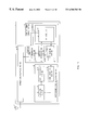
- FIG. 1 is a block diagram showing a configuration of a base station in Embodiment 1 of the present invention.
- Base station 1 in FIG. 1 mainly comprises transmission/reception section 20 that transmits/receives signals to/from a mobile station and receives a signal transmitted from another base station via antenna 10 , interference level measuring section 30 that measures the interference level of a signal received by transmission/reception section 20 and code assignment control section 40 that performs code type assignment control based on the measured interference level.
- Code assignment control section 40 comprises memory 41 that stores code types and memory 41 comprises all code list 42 that stores all code types in a list form and candidate code list 43 that stores code types to be assignment candidates in a list form.
- Code assignment control section 40 also comprises code reading section 44 that reads code types from all code list 42 and outputs them to interference level measuring section 30 , threshold determination section 45 that determines a code type to be an assignment candidate based on the interference level input from interference level measuring section 30 and a preset threshold and writes the code type to be an assignment candidate to candidate code list 43 and code determination section 46 that determines the code type of the station to be used from candidate code list 43 and outputs it to transmission/reception section 20 .
- Interference level measuring section 30 comprises code generation section 31 that generates codes based on a code type input from code reading section 44 , despreading section 32 that despreads a received signal multiplied by a code and level calculation section 33 that calculates the interference level of the despread signal.
- base station 1 determines the code type of the station
- the sections of the apparatus such as candidate code list 43 are initialized (ST 201 ), and code reading section 44 reads one code type to be searched from all code list 42 and outputs it to code generation section 31 of interference level measuring section 30 (ST 202 ).
- interference level measuring section 30 measures the level of an interference component of the received signal (ST 203 ).
- code generation section 31 generates a code based on the input code type
- despreading section 32 despreads the signal with the code generated
- level calculation section 33 calculates the level of the despread signal.
- threshold determination section 45 compares the interference level measured by interference level measuring section 30 with a preset threshold (ST 204 ) and if the interference level is lower than the threshold, the corresponding code type is written to candidate code list 43 (ST 205 ).
- code determination section 46 determines the code type of the station from among the code types stored in candidate code list 43 (ST 207 ).
- the code type of the station it is also possible to store not only code types but also interference levels in the candidate code list and determine the code type with the lowest interference level as the code type of the station. This allows communications with the code type of the best communication quality.
- the code type of the station it is also possible to store not only code types but also interference levels in the candidate code list and determine the code type with the highest interference level as the code type of the station. This makes it possible to improve the efficiency of repetitive use of a same code type and efficiently arrange base stations.
- Embodiment 2 is an embodiment giving priority to previously used codes in code assignment operation.
- FIG. 3 is a block diagram showing a configuration of a base station in Embodiment 2.
- code reading section 44 in base station 1 in FIG. 3 reads a previously used code type of the station which is held in code determination section 46 . If the interference level of the previously used code type of the station is lower than a threshold, threshold determination section 45 outputs the code type to code determination section 46 . When the code type is input from threshold determination section 45 , code determination section 46 outputs the code type to transmission/reception section as the code type of the station.
- the other components in base station 1 in FIG. 3 are the same as those in FIG. 1, and thus they are assigned the same numbers and their explanations are omitted.
- base station 1 determines the code type of the station
- the sections of the apparatus such as candidate code list 43 are initialized (ST 401 ), and then code reading section 44 reads the previously used code type from code determination section 46 and outputs it to code generation section 31 of interference level measuring section 30 (ST 402 ). Then, interference level measuring section 30 measures the level of an interference component of the received signal (ST 403 ).
- threshold determination section 45 compares the interference level measured by interference level measuring section 30 with a preset threshold (ST 404 ) and if the interference level is lower than the threshold, the previously used code type is output to code determination section 46 and code determination section 46 determines the code type as the code type of the station (ST 405 ).
- the subsequent operation when the interference level of the previously used code type is higher than the threshold is the same as the operations from ST 202 to ST 207 in the flow diagram in FIG. 2, and thus their explanations are omitted.
- preferentially using the previously used codes eliminates the need for measuring the interference level of other code types when the interference level of the previously used code type of the station is lower than a threshold, making it possible to shorten the time required for code assignment operation.
- Embodiment 3 is an embodiment that counts the number of times the interference level measured during a communication was lower than a threshold, determines priority based on the counted value and preferentially uses codes with high priority in code assignment operation.
- FIG. 5 is a block diagram showing a configuration of a base station in Embodiment 3.
- memory 41 only comprises all code list 42 and all code list 42 stores not only code types but also the number of times (hereinafter referred to as “count value”) the interference level measured during a communication of each code type was lower than the threshold.
- Threshold determination section 45 incorporates a counter and if the interference level of the code type measured during a communication was lower than the threshold, it increments the counter and stores the count value together with the code type in all code list 42 . Furthermore, threshold determination section 45 treats a code type with a higher count value as one with higher priority and sorts all code types in all code list 42 in descending order of priority.
- Code reading section 44 measures time with a built-in timer and reads the assigned code type of the station stored in code determination section 46 at regular intervals from the beginning of the communication. When carrying out code assignment operation, code reading section 44 reads code types from all code list 42 in descending order of priority.
- Level calculation section 33 subtracts the power level of the station input from transmission/reception section 20 from the interference level including the transmission power of the station calculated from the despread signal during the communication and calculates the true interference level.
- base station 1 in FIG. 5 The other components of base station 1 in FIG. 5 are the same as those in FIG. 1, and so they are assigned the same numbers as those in FIG. 1 and their explanations are omitted.
- the sections of the apparatus such as the timer of code reading section 44 are initialized (ST 601 ), code reading section 44 reads the code types whose interference level has not been measured yet with the highest priority and outputs it to code generation section 31 of interference level measuring section 30 (ST 602 ) and interference level measuring section 30 measures the level of an interference component of the received signal (ST 603 ).
- threshold determination section 45 compares the interference level measured by interference level measuring section 30 with a preset threshold (ST 604 ) and if the interference level is lower than the threshold, the code type is output to code determination section 46 and code determination section 46 determines the code type as the code type of the station (ST 605 ). If the interference level is higher than the threshold in ST 604 , the operations from ST 602 are repeated once again.
- the timer of code reading section 44 starts (ST 701 ). If a measurement continues for a certain period of time (ST 703 ) without power interruption (ST 702 ), the timer is reset (ST 704 ), and code reading section 44 reads the assigned code type of the station from code determination section 46 and outputs it to code generation section 31 of interference level measuring section 30 (ST 705 ).
- interference level measuring section 30 measures the level of an interference component of the received signal (ST 706 ).
- code generation section 31 generates a code based on the input code type
- despreading section 32 despreads the signal with the code generated
- level calculation section 33 subtracts the power level of the station input from transmission/reception section 20 from the interference level including the transmission power of the station calculated from the despread signal and calculates the true interference level.
- threshold determination section 45 compares the interference level measured by interference level measuring section 30 with a preset threshold (ST 707 ) and if the interference level is lower than the threshold, the built-in counter of threshold determination section 45 is incremented (ST 708 ) and the count value in all code list 42 is corrected (ST 709 ).
- a code type with a higher count value is treated as one with higher priority and all code types in all code list 42 are sorted in descending order of priority. (ST 710 )
- Embodiment 4 is an embodiment that determines priority based on the measured interference level and preferentially uses codes with higher priority in code assignment operation.
- FIG. 8 is a block diagram showing a configuration of a base station in Embodiment 4.
- memory 41 only comprises all code list 42 and all code list 42 stores code types as well as the interface level of each code type.
- Threshold determination section 45 treats a code type with a lower interference level as one with higher priority and sorts all code types in all code list 42 in descending order of priority.
- code reading section 44 reads code types from all code list 42 in descending order of priority.
- base station 1 in FIG. 8 The other components of base station 1 in FIG. 8 are the same as those in FIG. 1, and so they are assigned the same numbers as those in FIG. 1 and their explanations are omitted.
- code reading section 44 reads the code type with the highest priority whose interference level has not been measured yet and outputs it to code generation section 31 of interference level measuring section 30 (ST 902 ) and interference level measuring section 30 measures the level of an interference component of the received signal (ST 903 ).
- threshold determination section 45 updates the stored interference level to the interference level measured by interference measuring section 30 (ST 904 ) and at the same time compares the interference level measured by interference level measuring section 30 with a preset threshold (ST 905 ).
- the code type is output to code determination section 46 and code determination section 46 determines the code type as the code type of the station (ST 906 ) and treats a code type with a lower interference level as one with higher priority and sorts all code types in all code list 42 in descending order of priority (ST 907 ).
- ST 905 if the interference level is higher than the threshold, the operations from ST 902 are repeated once again.
- Embodiment 5 is an embodiment that measures the interference level of the assigned code of the station during a communication, determines priority based on the interference level measured and preferentially uses codes with higher priority in code assignment operation.
- Embodiment 5 The configuration of a base station in Embodiment 5 is the same as that in FIG. 5 and the code assignment operation at the base station in Embodiment 5 is the same as that in Embodiment 4, and so their explanations are omitted.
- the timer of code reading section 44 starts (ST 1001 ). If a measurement continues for a certain period of time (ST 1003 ) without power interruption (ST 1002 ), the timer is reset (ST 1004 ), and code reading section 44 reads the assigned code type of the station from code determination section 46 and outputs it to code generation section 31 of interference level measuring section 30 (ST 1005 ).
- interference level measuring section 30 measures the level of an interference component of the received signal (ST 1006 ).
- code generation section 31 generates a code based on the input code type
- despreading section 32 despreads the signal with the code generated
- level calculation section 33 subtracts the power level of the station input from transmission/reception section 20 from the interference level including the transmission power of the station calculated from the despread level and calculates the true interference level.
- threshold determination section 45 compares the interference level measured by interference level measuring section 30 with a preset threshold (ST 1007 ) and if the interference level is higher than the threshold, the interference level is considered to be the threshold (ST 1008 ) and the interference level in the corresponding code type in all code list 42 is updated to the threshold (ST 1009 ). If the interference level is lower than the threshold, the interference level in the corresponding code type in all code list 42 is updated to the measured interference level (ST 1009 ).
- a code type with a higher interference level is treated as one with higher priority and all code types in all code list 42 are sorted in order of priority (ST 1010 ).
- Embodiment 6 is an embodiment that determines priority based on a count value indicating the frequency of use and preferentially uses codes with higher priority in code assignment operation.
- FIG. 11 is a block diagram showing a configuration of a base station in Embodiment 6.
- memory 41 compared to base station 1 in FIG. 1, memory 41 only comprises all code list 42 and all code list 42 stores code types as well as a count value indicating the frequency of use.
- Code determination section 46 incorporates a counter, increments the counter of the code type adopted as the assigned code type of the station and stores the count value in all code list 42 .
- Threshold determination section 45 treats a code type with a higher count value as one with higher priority and sorts all code types in all code list 42 in descending order of priority.
- base station 1 in FIG. 11 The other components of base station 1 in FIG. 11 are the same as those in FIG. 1, and so they are assigned the same numbers as those in FIG. 1, and their explanations are omitted.
- code reading section 44 reads the code type with the highest priority whose interference level has not been measured yet and outputs it to code generation section 31 of interference level measuring section 30 (ST 1202 ) and interference level measuring section 30 measures the level of an interference component of the received signal (ST 1203 ).
- threshold determination section 45 compares the interference level measured by interference level measuring section 30 with a preset threshold (ST 1204 ) and if the interference level is lower than the threshold, the code type is output to code determination section 46 and code determination section 46 determines the code type as the code type of the station (ST 1205 ) and increments the counter indicating the frequency of use (ST 1206 ).
- the count value reaches a preset upper limit, it subtracts a certain value from the count values of all code types. However, if the count value after the subtraction is a negative value, the count value is set to 0. It is also possible to subtract a certain value only from the count value of the corresponding code type.
- threshold determination section 45 treats a code type with a higher count value as one with higher priority and sorts code types in all code list 42 in descending order of priority (ST 1207 ). In ST 1204 , if the interference level is higher than the threshold, the operations from ST 1202 are repeated once again.
- Embodiment 7 is an embodiment that fixes priority for a first code type group and determines priority based on the interference level measured for a second code type group and preferentially uses codes with higher priority in code assignment operation.
- the first code type group is a code type group having the same priority at all base stations and the second code type group is a code group having priority specific to each base station.
- FIG. 13 is a block diagram showing a configuration of a base station in Embodiment 7.
- all code list 42 stores code types divided into a first code type group and a second code type group and the second code type group is stored together with the interference level of each code type.
- Threshold determination section 45 treats code types in the second code type group with a lower interference level as ones with higher priority, and sorts code types in all code list 42 in descending order of priority.
- code reading section 44 When carrying out code assignment operation, code reading section 44 reads code types of the first code type group in descending order of priority, and then reads code types of the second code type group in descending order of priority.
- base station 1 in FIG. 13 The other components in base station 1 in FIG. 13 are the same as those in FIG. 8, and so they are assigned the same numbers as those in FIG. 8 and their explanations are omitted.
- code reading section 44 reads the code type in the first code type group with the highest priority whose interference level has not been measured yet and outputs it to code generation section 31 of interference level measuring section 30 (ST 1402 ) and interference level measuring section 30 measures the level of an interference component of the received signal (ST 1403 ).
- threshold determination section 45 compares the interference level measured by interference level measuring section 30 with a preset threshold (ST 1404 ) and if the interference level is lower than the threshold, the code type is output to code determination section 46 and code determination section 46 determines the code type as the code type of the station (ST 1405 ).
- interference level measuring section 30 measures the level of an interference component of the received signal (ST 1408 ) and threshold determination section 45 updates the stored interference level to the interference level measured by interference level measuring section 30 (ST 1409 ).
- threshold determination section 45 compares the interference level measured by interference level measuring section 30 with a preset threshold (ST 1410 ) and if the interference level is lower than the threshold, the code type is output to code determination section 46 and code determination section 46 determines the code type as the code type of the station (ST 1411 ).
- a code type with a lower interference level is treated as one with higher priority and all code types in the second code type group are sorted in descending order of priority (ST 1412 ).
- ST 1410 if the interference level is higher than the threshold, the operations from ST 1407 are repeated once again.
- Embodiment 8 is an embodiment that randomly selects a certain number of code types in code assignment operation, preferentially measures the interference level from the selected codes and uses them as the assigned codes of the station.
- a base station in Embodiment 8 is the same as the base station shown in FIG. 1 .
- code reading section 44 of base station 1 in Embodiment 8 randomly selects a certain number of code types from all code list 42 , reads the selected code types one by one and outputs them to interference level measuring section 30 .
- code reading section 44 selects a certain number of code types to be searched from all code list 42 (ST 1602 ), reads one code type from among the selected code types and outputs it to code generation section 31 of interference level measuring section 30 (ST 1603 ).
- interference level measuring section 30 measures the level of an interference component of the received signal (ST 1604 ) and threshold determination section 45 compares the interference level measured by interference level measuring section 30 with a preset threshold (ST 1605 ) and if the interference level is lower than the threshold, the corresponding code type as well as the interference level is written to candidate code list 43 (ST 1606 ).
- code determination section 46 determines the code type stored in candidate code list 43 with the lowest interference level as the code type of the station (ST 1609 ). In ST 1608 , if there is no assignment candidate code, a certain number of code types to be searched from among the code types that have not been selected yet and the operations from ST 1603 to ST 1607 are repeated (ST 1602 ).
- Embodiment 9 is a code assignment method by which a radio communication system classifies code types into several groups and assigns one of them to each base station as a preferred group.
- a base station in Embodiment 9 is the same as the base station shown in FIG. 1 .
- code reading section 44 of base station 1 in Embodiment 9 sets a code group to be searched from all code list 42 , reads the set code types one by one and outputs them to interference level measuring section 30 .
- threshold determination section 45 deletes all code type data included in the code group to which the code type belongs from candidate code list 43 .
- code reading section 44 sets a code group to be searched from all code list 42 (ST 1702 ), reads one code type from the selected code group and outputs it to code generation section 31 of interference level measuring section 30 (ST 1703 ).
- interference level measuring section 30 measures the level of an interference component of the received signal (ST 1704 ) and threshold determination section 45 compares the interference level measured by interference level measuring section 30 with a preset threshold (ST 1705 ) and if the interference level is lower than the threshold, the corresponding code type as well as the interference level is written to candidate code list 43 (ST 1706 ).
- code determination section 46 determines the code type stored in candidate code list 43 with the lowest interference level as the code type of the station (ST 1710 ).
- the code group containing the code type determined as the code type of the station is designated as the preferred group of the station.
- Embodiment 10 is a code assignment method when there are a plurality of channels on an assigned frequency axis.
- FIG. 18 is a block diagram showing a configuration of a base station in Embodiment 10 of the present invention.
- Base station 1 in FIG. 18 mainly comprises transmission/reception section 20 that transmits/receives signals to/from a mobile station and receives an interference signal transmitted from another base station via antenna 10 , interference level measuring section 30 that measures the interference level of a signal received by transmission/reception section 20 , code assignment control section 40 that carries out code type assignment control based on the interference level, reception level measuring section 50 that measures the reception level of the signal received by transmission/reception section 20 and channel assignment control section 60 that carries out channel assignment control based on the measured reception level.
- Channel assignment control section 60 comprises memory 61 that stores channels and memory 61 comprises all channel list 62 that stores all channels in a list form and candidate channel list 63 that stores assignment candidate channels in a list form.
- Channel assignment control section 60 also comprises channel setting section 64 that sets channels to be measured from all channel list 62 and outputs them to reception level measuring section 50 , threshold determination section 65 that determines assignment candidate channels from the reception level input from reception level measuring section 50 and a preset threshold and writes the channel number to be an assignment candidate to candidate channel list 63 and channel determination section 66 that determines the channel of the station used from candidate channel list 63 and outputs it to code assignment control section 40 .
- Interference level measuring section 30 and code assignment control section 40 adopts one of Embodiment 1 to Embodiment 9.
- channel setting section 64 reads one channel to be searched from all channel list 62 and outputs it to reception level measuring section 50 (ST 1902 ) and reception level measuring section 50 measures the reception level of the received signal (ST 1903 ).
- threshold determination section 65 compares the reception level measured by reception level measuring section 50 with a preset threshold (ST 1904 ) and if the reception level is lower than the threshold, the corresponding channel number is written to candidate channel list 63 (ST 1905 ).
- interference level measuring section 30 and code assignment control section 40 carry out the code assignment operation explained in one of Embodiment 1 to Embodiment 9 and determine the code type of the station.
- measuring the reception level for each channel determining the channel of the station and carrying out code assignment operation through the determined channel of the station eliminates the need for theoretical design for assigning codes to all base stations even if there are a plurality of channels on the assigned frequency axis.
- the method of determining the channel of the station it is also possible to store channels as well as the reception levels in the candidate channel list and determine the one with the lowest reception level as the channel of the station. This allows communications using the channel with the best communication quality.
- the method of determining the channel of the station it is also possible to store channels as well the reception levels in the candidate channel list and determine the one with the highest reception level as the channel of the station. This makes it possible to improve the efficiency in repeatedly using the same channel and efficiently arrange base stations.
- the frequency of implementing code assignment operation can be set as appropriate such as implementing code assignment operation at specific intervals or when power is turned on.
- the base station apparatus in the embodiments above can switch code types when the communication quality deteriorates by the mobile station apparatus monitoring the communication quality and reporting it to the base station apparatus and the base station apparatus carrying out code assignment operation based on the communication quality related information from the mobile station apparatus.
- FIG. 20 is a system diagram showing a radio communication system including the CDMA base station apparatus of the present invention.
- Mobile station apparatus 2 and mobile station apparatus 3 in FIG. 20 are located in a radio zone which is an area allowing communications with base station apparatus 1 and have a function to monitor the communication quality and report it to the base station apparatus.
- base station apparatus 1 transmits a signal to mobile station apparatus 2 and mobile station apparatus 3 using code type n and the transmission/reception section determines whether the communication quality has deteriorated or not based on the communication quality related information received from mobile station apparatus 2 and mobile station apparatus 3 .
- base station apparatus 1 determines that the communication quality has deteriorated, it first determines code type m to be updated using the code assignment method explained in one of the embodiments above.
- base station apparatus 1 notifies mobile station apparatus 2 and mobile station apparatus 3 of the time required until the code is changed.
- base station apparatus 1 switches code type n to code type m.
- switching a code type when the communication quality deteriorates can maintain the communication quality optimal even if interference from neighboring cells occurs.
- code types to be searched it is possible to share code types to be searched between the base station and mobile station, search respective shared code types, report the search results from the mobile station to the base station, organize the search results by the base station and switch the code types based on these search results.
- the mobile station can perform RAKE reception with a plurality of code types, it is also possible, when switching code types, for the base station to transmit a signal using both code types before and after the update and for the mobile station to perform RAKE reception of both code types before and after the update.
- the CDMA base station apparatus and code assignment method of the present invention can eliminate the need for theoretical design for assigning codes to all base stations even if a new base station is added.
Abstract
Description
Claims (16)
Applications Claiming Priority (2)
| Application Number | Priority Date | Filing Date | Title |
|---|---|---|---|
| JP26960898A JP3149399B2 (en) | 1998-09-24 | 1998-09-24 | CDMA base station apparatus and code allocation method |
| JP10-269608 | 1998-09-24 |
Publications (1)
| Publication Number | Publication Date |
|---|---|
| US6580703B1 true US6580703B1 (en) | 2003-06-17 |
Family
ID=17474735
Family Applications (1)
| Application Number | Title | Priority Date | Filing Date |
|---|---|---|---|
| US09/391,092 Expired - Lifetime US6580703B1 (en) | 1998-09-24 | 1999-09-16 | CDMA base station apparatus and code assignment method |
Country Status (5)
| Country | Link |
|---|---|
| US (1) | US6580703B1 (en) |
| EP (1) | EP0989686A3 (en) |
| JP (1) | JP3149399B2 (en) |
| KR (1) | KR100316839B1 (en) |
| CA (1) | CA2282774A1 (en) |
Cited By (8)
| Publication number | Priority date | Publication date | Assignee | Title |
|---|---|---|---|---|
| US20020003782A1 (en) * | 2000-07-10 | 2002-01-10 | Interdigital Technology Corporation | Code power measurement for dynamic channel allocation |
| US20030156634A1 (en) * | 2002-02-19 | 2003-08-21 | Stefan Zurbes | Method of and system for interference measurement |
| US7139284B1 (en) * | 1999-11-01 | 2006-11-21 | Nec Corporation | Spread code allocation method and base station in CDMA cellular |
| US20060271704A1 (en) * | 2000-04-16 | 2006-11-30 | Wai-Chung Chan | Approach to minimize worst-case queueing delay for a switching communication system with transmission constraints |
| US20090181688A1 (en) * | 2008-01-11 | 2009-07-16 | Lucent Technologies Inc. Via The Electronic Patent Assignment System (Epas) | Automatic allocation of area codes for femtocell deployment |
| CN1934893B (en) * | 2004-03-24 | 2010-11-03 | 日本电气株式会社 | Base station device and initialization method thereof |
| CN101395942B (en) * | 2006-03-01 | 2012-10-10 | 日本电气株式会社 | Mobile communication system, its scramble code assigning method, mobile station, and base station |
| US20130143612A1 (en) * | 2011-12-01 | 2013-06-06 | Telefonaktiebolaget L M Ericsson (Publ) | Methods and Communication Devices in a Radio Telecommunications Network |
Families Citing this family (6)
| Publication number | Priority date | Publication date | Assignee | Title |
|---|---|---|---|---|
| US7151761B1 (en) | 1999-03-19 | 2006-12-19 | Telefonaktiebolaget L M Ericsson (Publ) | Code reservation for interference measurement in a CDMA radiocommunication system |
| SG93286A1 (en) * | 2000-11-24 | 2002-12-17 | Sony Electronics Singapore Pte | Resource allocation in cdma wireless communication systems |
| KR100454955B1 (en) * | 2002-08-07 | 2004-11-06 | 삼성전자주식회사 | Method for cell id code assignation in mobile communication system |
| JP4128880B2 (en) * | 2003-01-16 | 2008-07-30 | 株式会社エヌ・ティ・ティ・ドコモ | Radio control apparatus and spreading code selection method |
| JP4451286B2 (en) | 2004-11-12 | 2010-04-14 | 株式会社エヌ・ティ・ティ・ドコモ | Base station, base station control station, mobile communication system, and scrambling code setting method |
| JP4755935B2 (en) * | 2006-04-04 | 2011-08-24 | 株式会社エヌ・ティ・ティ・ドコモ | Wireless base station and wireless communication parameter duplication detection method |
Citations (7)
| Publication number | Priority date | Publication date | Assignee | Title |
|---|---|---|---|---|
| US5345469A (en) * | 1993-02-01 | 1994-09-06 | Motorola, Inc. | Communication device with code sequence selection system |
| CA2116601A1 (en) | 1993-03-10 | 1994-09-11 | Narumi Umeda | Mobile Station and Cell Selecting Method for Code Division Multiplex Access Mobile Communication |
| JPH09102979A (en) | 1995-10-06 | 1997-04-15 | Nec Corp | Mobile communication system |
| US5640414A (en) * | 1992-03-05 | 1997-06-17 | Qualcomm Incorporated | Mobile station assisted soft handoff in a CDMA cellular communications system |
| US5652748A (en) * | 1993-09-20 | 1997-07-29 | Nokia Telecommunications Oy | Method for making a handover in a CDMA cellular radio system, and a mobile station |
| US6128288A (en) * | 1996-12-26 | 2000-10-03 | Matsushita Electric Industrial Co., Ltd. | CDMA cellular radio transmission system |
| US6343070B1 (en) * | 1998-06-08 | 2002-01-29 | Ericcson Inc. | Methods for reducing channel acquisition times in a radiotelephone communications system and related mobile terminals |
Family Cites Families (2)
| Publication number | Priority date | Publication date | Assignee | Title |
|---|---|---|---|---|
| US5402413A (en) * | 1991-04-08 | 1995-03-28 | Omnipoint Corporation | Three-cell wireless communication system |
| JPH10126842A (en) * | 1996-10-18 | 1998-05-15 | Matsushita Electric Ind Co Ltd | Mobile communication system |
-
1998
- 1998-09-24 JP JP26960898A patent/JP3149399B2/en not_active Expired - Lifetime
-
1999
- 1999-09-16 US US09/391,092 patent/US6580703B1/en not_active Expired - Lifetime
- 1999-09-16 EP EP19990118409 patent/EP0989686A3/en not_active Withdrawn
- 1999-09-17 CA CA 2282774 patent/CA2282774A1/en not_active Abandoned
- 1999-09-22 KR KR1019990040915A patent/KR100316839B1/en active IP Right Grant
Patent Citations (7)
| Publication number | Priority date | Publication date | Assignee | Title |
|---|---|---|---|---|
| US5640414A (en) * | 1992-03-05 | 1997-06-17 | Qualcomm Incorporated | Mobile station assisted soft handoff in a CDMA cellular communications system |
| US5345469A (en) * | 1993-02-01 | 1994-09-06 | Motorola, Inc. | Communication device with code sequence selection system |
| CA2116601A1 (en) | 1993-03-10 | 1994-09-11 | Narumi Umeda | Mobile Station and Cell Selecting Method for Code Division Multiplex Access Mobile Communication |
| US5652748A (en) * | 1993-09-20 | 1997-07-29 | Nokia Telecommunications Oy | Method for making a handover in a CDMA cellular radio system, and a mobile station |
| JPH09102979A (en) | 1995-10-06 | 1997-04-15 | Nec Corp | Mobile communication system |
| US6128288A (en) * | 1996-12-26 | 2000-10-03 | Matsushita Electric Industrial Co., Ltd. | CDMA cellular radio transmission system |
| US6343070B1 (en) * | 1998-06-08 | 2002-01-29 | Ericcson Inc. | Methods for reducing channel acquisition times in a radiotelephone communications system and related mobile terminals |
Non-Patent Citations (1)
| Title |
|---|
| English Language Abstract of JP 9-102979. |
Cited By (13)
| Publication number | Priority date | Publication date | Assignee | Title |
|---|---|---|---|---|
| US7139284B1 (en) * | 1999-11-01 | 2006-11-21 | Nec Corporation | Spread code allocation method and base station in CDMA cellular |
| US7370116B2 (en) * | 2000-04-16 | 2008-05-06 | Hughes Network Systems, Llc | Approach to minimize worst-case queuing delay for a switching communication system with transmission constraints |
| US20060271704A1 (en) * | 2000-04-16 | 2006-11-30 | Wai-Chung Chan | Approach to minimize worst-case queueing delay for a switching communication system with transmission constraints |
| US20060072518A1 (en) * | 2000-07-10 | 2006-04-06 | Interdigital Technology Corporation | Code power measurement for dynamic channel allocation |
| US20020003782A1 (en) * | 2000-07-10 | 2002-01-10 | Interdigital Technology Corporation | Code power measurement for dynamic channel allocation |
| US6993002B2 (en) * | 2000-07-10 | 2006-01-31 | Interdigital Technology Corp. | Code power measurement for dynamic channel allocation |
| US7142593B2 (en) * | 2002-02-19 | 2006-11-28 | Telefonaktiebolaget Lm Ericsson (Publ) | Method of and system for interference measurement |
| US20030156634A1 (en) * | 2002-02-19 | 2003-08-21 | Stefan Zurbes | Method of and system for interference measurement |
| CN1934893B (en) * | 2004-03-24 | 2010-11-03 | 日本电气株式会社 | Base station device and initialization method thereof |
| CN101395942B (en) * | 2006-03-01 | 2012-10-10 | 日本电气株式会社 | Mobile communication system, its scramble code assigning method, mobile station, and base station |
| US20090181688A1 (en) * | 2008-01-11 | 2009-07-16 | Lucent Technologies Inc. Via The Electronic Patent Assignment System (Epas) | Automatic allocation of area codes for femtocell deployment |
| US20130143612A1 (en) * | 2011-12-01 | 2013-06-06 | Telefonaktiebolaget L M Ericsson (Publ) | Methods and Communication Devices in a Radio Telecommunications Network |
| US8676127B2 (en) * | 2011-12-01 | 2014-03-18 | Telefonaktiebolaget Lm Ericsson (Publ) | Methods and communication devices in a radio telecommunications network |
Also Published As
| Publication number | Publication date |
|---|---|
| CA2282774A1 (en) | 2000-03-24 |
| KR20000023383A (en) | 2000-04-25 |
| KR100316839B1 (en) | 2001-12-24 |
| JP3149399B2 (en) | 2001-03-26 |
| EP0989686A3 (en) | 2003-06-25 |
| JP2000102064A (en) | 2000-04-07 |
| EP0989686A2 (en) | 2000-03-29 |
Similar Documents
| Publication | Publication Date | Title |
|---|---|---|
| US6580703B1 (en) | CDMA base station apparatus and code assignment method | |
| US6233454B1 (en) | Mobile station | |
| KR100291761B1 (en) | Cdma cellular radio transmission system | |
| US5889768A (en) | Method of and apparatus for pilot channel acquisition | |
| CA2187412C (en) | Method for setting up perch channels in mobile communication by cellular system | |
| CA2371205C (en) | Cell search appratus and method in cdma mobile communication system | |
| US8125887B2 (en) | Mobile communication system, its scramble code assigning method, mobile station, and base station | |
| US5832384A (en) | Method and apparatus for frequency agility in a communication system | |
| US7272409B2 (en) | Method and apparatus for setting pilot signal transmit powers | |
| US6539006B1 (en) | Mobile station capable of determining base station suitability | |
| US8837436B2 (en) | Code division multiple access mobile communication system | |
| US7031373B1 (en) | Apparatus for controlling a plurality of receiver fingers in a CDMA receiver | |
| KR100291294B1 (en) | Cdma mobile communication system | |
| US6633556B1 (en) | Mobile communications system and mobile communications method | |
| US20050085230A1 (en) | Circuit and method for producing a pilot strength measurement message | |
| US7453863B2 (en) | Cell searching apparatus and method in asynchronous mobile communication system | |
| EP1143757A1 (en) | Mobile communication terminal and handover control method | |
| US6707847B1 (en) | Method and apparatus for detecting a spread code from a perch channel | |
| JP3148506B2 (en) | Mobile communication cell determination method and mobile station device thereof | |
| US7072677B2 (en) | Method of operating searcher in a mobile communication system | |
| KR100291037B1 (en) | Method for acquiring of mobile station signal in code division multiple access system | |
| KR101796439B1 (en) | signal analyzing apparatus and method for WCDMA | |
| JP2000049751A (en) | Rake receiver and path detection circuit | |
| JPH0833022A (en) | Modem for specified small power radio transmission | |
| KR20060077855A (en) | Set maintenance method for a mobile terminal in a code division multiple access system and pilot channel searcher using the same |
Legal Events
| Date | Code | Title | Description |
|---|---|---|---|
| AS | Assignment |
Owner name: MATSUSHTA ELECTRIC INDUSTRIAL CO., LTD., JAPAN Free format text: ASSIGNMENT OF ASSIGNORS INTEREST;ASSIGNORS:OKUBO, YOSHIYUKI;ASANO, NOBUO;HORIKAWA, IZUMI;REEL/FRAME:010261/0863 Effective date: 19990715 |
|
| STCF | Information on status: patent grant |
Free format text: PATENTED CASE |
|
| FEPP | Fee payment procedure |
Free format text: PAYOR NUMBER ASSIGNED (ORIGINAL EVENT CODE: ASPN); ENTITY STATUS OF PATENT OWNER: LARGE ENTITY |
|
| FPAY | Fee payment |
Year of fee payment: 4 |
|
| FPAY | Fee payment |
Year of fee payment: 8 |
|
| FEPP | Fee payment procedure |
Free format text: PAYOR NUMBER ASSIGNED (ORIGINAL EVENT CODE: ASPN); ENTITY STATUS OF PATENT OWNER: LARGE ENTITY Free format text: PAYER NUMBER DE-ASSIGNED (ORIGINAL EVENT CODE: RMPN); ENTITY STATUS OF PATENT OWNER: LARGE ENTITY |
|
| AS | Assignment |
Owner name: PANASONIC CORPORATION, JAPAN Free format text: CHANGE OF NAME;ASSIGNOR:MATSUSHITA ELECTRIC INDUSTRIAL CO., LTD.;REEL/FRAME:031814/0732 Effective date: 20081001 |
|
| AS | Assignment |
Owner name: HIGHBRIDGE PRINCIPAL STRATEGIES, LLC, AS COLLATERA Free format text: LIEN;ASSIGNOR:OPTIS WIRELESS TECHNOLOGY, LLC;REEL/FRAME:032180/0115 Effective date: 20140116 |
|
| AS | Assignment |
Owner name: OPTIS WIRELESS TECHNOLOGY, LLC, TEXAS Free format text: ASSIGNMENT OF ASSIGNORS INTEREST;ASSIGNOR:PANASONIC CORPORATION;REEL/FRAME:032326/0707 Effective date: 20140116 |
|
| AS | Assignment |
Owner name: WILMINGTON TRUST, NATIONAL ASSOCIATION, MINNESOTA Free format text: SECURITY INTEREST;ASSIGNOR:OPTIS WIRELESS TECHNOLOGY, LLC;REEL/FRAME:032437/0638 Effective date: 20140116 |
|
| FPAY | Fee payment |
Year of fee payment: 12 |
|
| AS | Assignment |
Owner name: OPTIS WIRELESS TECHNOLOGY, LLC, TEXAS Free format text: RELEASE BY SECURED PARTY;ASSIGNOR:HPS INVESTMENT PARTNERS, LLC;REEL/FRAME:039361/0001 Effective date: 20160711 |