US7006795B2 - Wireless communication system with interference compensation - Google Patents
Wireless communication system with interference compensation Download PDFInfo
- Publication number
- US7006795B2 US7006795B2 US10/005,650 US565001A US7006795B2 US 7006795 B2 US7006795 B2 US 7006795B2 US 565001 A US565001 A US 565001A US 7006795 B2 US7006795 B2 US 7006795B2
- Authority
- US
- United States
- Prior art keywords
- terminals
- signals
- order
- interference
- operating parameter
- Prior art date
- Legal status (The legal status is an assumption and is not a legal conclusion. Google has not performed a legal analysis and makes no representation as to the accuracy of the status listed.)
- Expired - Lifetime, expires
Links
Images


Classifications
-
- H—ELECTRICITY
- H04—ELECTRIC COMMUNICATION TECHNIQUE
- H04W—WIRELESS COMMUNICATION NETWORKS
- H04W52/00—Power management, e.g. TPC [Transmission Power Control], power saving or power classes
- H04W52/04—TPC
- H04W52/30—TPC using constraints in the total amount of available transmission power
- H04W52/34—TPC management, i.e. sharing limited amount of power among users or channels or data types, e.g. cell loading
- H04W52/343—TPC management, i.e. sharing limited amount of power among users or channels or data types, e.g. cell loading taking into account loading or congestion level
-
- H—ELECTRICITY
- H04—ELECTRIC COMMUNICATION TECHNIQUE
- H04L—TRANSMISSION OF DIGITAL INFORMATION, e.g. TELEGRAPHIC COMMUNICATION
- H04L1/00—Arrangements for detecting or preventing errors in the information received
- H04L1/0001—Systems modifying transmission characteristics according to link quality, e.g. power backoff
- H04L1/0002—Systems modifying transmission characteristics according to link quality, e.g. power backoff by adapting the transmission rate
-
- H—ELECTRICITY
- H04—ELECTRIC COMMUNICATION TECHNIQUE
- H04L—TRANSMISSION OF DIGITAL INFORMATION, e.g. TELEGRAPHIC COMMUNICATION
- H04L1/00—Arrangements for detecting or preventing errors in the information received
- H04L1/0001—Systems modifying transmission characteristics according to link quality, e.g. power backoff
- H04L1/0015—Systems modifying transmission characteristics according to link quality, e.g. power backoff characterised by the adaptation strategy
-
- H—ELECTRICITY
- H04—ELECTRIC COMMUNICATION TECHNIQUE
- H04L—TRANSMISSION OF DIGITAL INFORMATION, e.g. TELEGRAPHIC COMMUNICATION
- H04L1/00—Arrangements for detecting or preventing errors in the information received
- H04L1/004—Arrangements for detecting or preventing errors in the information received by using forward error control
- H04L1/0056—Systems characterized by the type of code used
- H04L1/0057—Block codes
-
- H—ELECTRICITY
- H04—ELECTRIC COMMUNICATION TECHNIQUE
- H04L—TRANSMISSION OF DIGITAL INFORMATION, e.g. TELEGRAPHIC COMMUNICATION
- H04L25/00—Baseband systems
- H04L25/02—Details ; arrangements for supplying electrical power along data transmission lines
- H04L25/03—Shaping networks in transmitter or receiver, e.g. adaptive shaping networks
- H04L25/03006—Arrangements for removing intersymbol interference
- H04L25/03343—Arrangements at the transmitter end
-
- H—ELECTRICITY
- H04—ELECTRIC COMMUNICATION TECHNIQUE
- H04W—WIRELESS COMMUNICATION NETWORKS
- H04W52/00—Power management, e.g. TPC [Transmission Power Control], power saving or power classes
- H04W52/04—TPC
- H04W52/30—TPC using constraints in the total amount of available transmission power
- H04W52/34—TPC management, i.e. sharing limited amount of power among users or channels or data types, e.g. cell loading
- H04W52/346—TPC management, i.e. sharing limited amount of power among users or channels or data types, e.g. cell loading distributing total power among users or channels
Definitions
- This invention relates to wireless communication systems and, more particularly, to wireless communication systems that use techniques that compensate for interference among signals within the system.
- weighting can be, for example, the revenue per bit per second associated with the mobile terminal.
- the present inventors have realized that it is advantageous to assign an operating parameter value, such as a data rate and/or power level, to the terminals without determining the highest theoretical system throughput, and without determining the highest weighted system throughput. This can be accomplished by imposing an order on the terminals and assigning the operating parameter such that at least one of operating parameter values of terminals that have a lower index in the order will not be made worse due to the presence of terminals having a higher index in the order.
- an operating parameter value such as a data rate and/or power level
- a terminals index in the order is its order number, so a terminal that is first in the order has the lowest order index, of one, and a terminal that is second in the order has an index of two and is higher in the order than the terminal whose index is one.
- the assignment is made to the terminals based on the terminals requirements without regard to the interference introduced by the terminals with a higher index in the order since this interference will be compensated for by the compensation technique when the compensation technique process the terminals in accordance with the order.
- Assigning the data rate and/or power level to the mobile terminals without determining the theoretical highest system throughput, and without determining the highest weighted system throughput is in marked contrast to the prior art approach in which at least one of the above is maximized through complex calculations.
- the invention reduces the amount of computation necessary to implement such techniques on an ongoing, real-time basis in a real-world system.
- the order can be determined randomly or, alternatively, the order can be based on some predefined criterion or criteria that may prove advantageous in using as much system throughput as possible without actually having to calculate the theoretically highest system throughput.
- the order can be based on the order in which the mobile terminals initiated a communication session with the base station(s) (either ascending or descending); the order might be based on the amount of data to be transmitted to or from the various mobile terminals (also either ascending or descending); or the order might be based on which mobile terminal could make best use of the communication resources on an individual basis (as opposed to the overall basis used in the prior art calculations).
- an order can be imposed for downlink signals, for uplink signals, or for both. In the case where the order is imposed for both, the same criteria can be used to determine the order on both downlink and uplink communications, or alternatively different criteria can be used for downlink and uplink communication.
- FIG. 1 illustrates a portion of a wireless communication system
- FIG. 2 a illustrates in more detail a cell of the wireless communication system of FIG. 1 when multi-user detection is used to compensate for interference among signals within the cell;
- FIG. 2 b illustrates in more detail a cell of the wireless communication system of FIG. 1 when multi-user detection is used to compensate for interference among signals within the cell, and where the base station and at least some of the mobile terminals communicate using multiple antennas;
- FIG. 3 is a table illustrating for the cell shown in FIG. 2 a which terminals' signals are taken account of in compensating for interference in which other terminals' signals when multi-user detection is used;
- FIG. 4 a illustrates in more detail a cell of the wireless communication system of FIG. 1 when dirty paper coding is used to compensate for interference among signals within the cell;
- FIG. 4 b illustrates a plurality of voltage intervals used for explaining a simple version of dirty paper coding
- FIG. 5 illustrates in more detail a cell of the wireless communication system of FIG. 1 when dirty paper coding is used on the downlink and multi-user detection is used on the uplink in accordance with an embodiment of the invention
- FIG. 6 illustrates in more detail a cell of the wireless communication system of FIG. 1 when an order is imposed on the mobile terminals in the cell, pursuant to the principles of the invention, and multi-user detection is used to compensate for interference among signals within the cell;
- FIG. 7 illustrates in more detail a cell of the wireless communication system of FIG. 1 when the order is imposed on the mobile terminals in the cell and dirty-paper coding is used to compensate for interference among signals within the cell;
- FIG. 8 illustrates in more detail a cell of the wireless communication system of FIG. 1 when the order is imposed on the mobile terminals in the cell, pursuant to the principles of the invention, and dirty-paper coding is used on the downlink and multi-user detection is used on the uplink in accordance with an embodiment of the invention;
- FIG. 9 illustrates in more detail a multi-cell portion of the wireless communication system of FIG. 1 when the order is imposed on the mobile terminals in the cells, pursuant to the principles of the invention, and dirty-paper coding is used on the downlink and multi-user detection is used on the uplink in accordance with an embodiment of the invention;
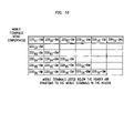
- FIG. 10 is a table illustrating for the portion of the system shown in FIG. 9 which terminals' signals are taken account of in compensating for interference in which other terminals' signals when the order and multi-user detection are used;
- FIG. 11 illustrates a wireless communication system similar to that shown in FIG. 1 where the order is imposed on the mobile terminals in the entire wireless communication system, pursuant to the principles of the invention, and dirty-paper coding is used on the downlink and multi-user detection is used on the uplink in accordance with an embodiment of the invention.
- FIG. 1 illustrates a portion of a wireless communication system 100 .
- the geographic area serviced by system 100 is divided into a plurality of spatially distinct areas called “cells.”
- cells 110 1 , . . . 100 15 are illustrated as a hexagon in a honeycomb pattern, each cell is actually of an irregular shape that depends on obstacles and topography in the geographical area.
- Each cell 110 1 , . . . 100 15 contains a base station 115 1 . . . 115 15 , respectively.
- Each base station 115 1 . . . 115 15 includes equipment to communicate with Mobile Switching Center (“MSC”) (not shown), which is connected to local and/or long-distance transmission network, such as a public switch telephone network (PSTN).
- MSC Mobile Switching Center
- PSTN public switch telephone network
- Each base station 115 1 . . . 115 15 also includes radios and antennas that the base station uses to communicate with mobile terminals.
- signals transmitted between base stations and mobile terminals within a wireless communication system interfere with one another to some extent, thereby negatively affecting the ability of the system to accurately receive and decode these signals.
- Various techniques are known to compensate for such interference. Among these techniques are multi-user detection and dirty paper coding.
- multi-user detection estimates the interference in a received signal and subtracts this estimated interference from the signal.
- multi-user detection see, for example, S. Verdu, MULTI USER DETECTION, Cambridge University Press, pp. 154–233, 1998, incorporated herein by this reference.
- FIG. 2 a illustrates cell 110 5 of wireless communication system 100 when multi-user detection is used to compensate for interference among signals within the cell.
- the cell is represented by 110 5 -M, with M used throughout the description and figures to represent that multi-user detection is used.
- Cell 110 5 -M includes base station 115 5 -M that communicates with mobile terminals 120 51 -M, 120 52 -M, and 120 53 -M over an uplink and a downlink.
- the uplink includes communication channels for transmitting signals 125 51 , 125 52 , and 125 53 —commonly referred to as uplink signals—from mobile terminals 120 51 -M, 120 52 -M, and 120 53 -M, respectively, to base station 115 5 -M.
- the downlink includes communication channels for transmitting signals 130 51 , 130 52 , and 130 53 —commonly referred to as downlink signals—from base station 115 5 -M to mobile terminals 120 51 -M, 120 52 -M, and 120 53 -M, respectively.
- Multi-user detection can be used on either the uplink, or the downlink, or both.
- base station 115 5 -M receives a received signal that includes all three uplink signals 125 51 , 125 52 , and 125 53 . Because these signals scatter off of objects in the environment and because they have a wide angle of propagation, typically somewhere between 60° and 360°, these signals interfere with one another, thereby negatively affecting the ability of base station 115 5 -M to use the received signal to accurately decode uplink signals 125 51 , 125 52 , and 125 53 . Multi-user detection can be used to compensate for some of such interference. To use multi-user detection the base station should decode these received signals in an order.
- the base station then can either 1) determine the theoretical highest system throughput when multi-user detection uses this order, as in the prior art, and assign the data rates and/or power levels based on this calculation or 2) use multi-user detection using this order and determine the data rates and/or power levels assigned to the mobile terminals based on the requirements of the mobile terminals without regard to the interference introduced by the terminals having a higher index in the order, as described in more detail below.
- the order of the signals is 125 51 first (it will not be interfered with by signals 125 52 and 125 53 ), signal 125 52 second (it can be interfered with by signal 125 51 , but it will not be interfered with by signal 125 53 ), and signal 125 53 third (it can be interfered with by both 125 51 and 125 52 ).
- base station 115 5 -M will decode signal 125 53 first, signal 125 52 second, and signal 125 51 third.
- signal 125 53 can be decoded even in the presence of signals 125 51 and 125 52 .
- the decoded signal is used to reconstruct signal 125 53 .
- Signal 125 53 is reconstructed into the form in which it was received by base station 115 5 -M.
- the signal is reconstructed by first encoding the decoded signal using the coding techniques used to originally encode the signal at the transmitter, and then adjusting this signal to reflect the effect that the channel between the mobile terminal and the base station had on the signal. The latter is accomplished using the channel characteristics of this channel. (Note, the channel characterizations are typically determined by the receiver prior to the start of the data bursts that make up the communications. After receiver determines them it transmits the channel characterization to transmitter. In some cases, for example, so-called time duplexed communication, the transmitter can determine the channel characteristics prior to the start of the data bursts.)
- the reconstructed signal is then subtracted from the received signal. This reduces the effect of interference for the remaining signals, i.e. 125 51 and 125 52 , since once signal 125 53 is subtracted it is effectively no longer interference for these other signals.
- signal 125 52 can be sent at a higher data rate and/or a lower power level than if there was no such interference compensation, and still be decoded with an acceptable error rate. This is because when signal 125 53 is subtracted out, the interference from this signal to signal 125 52 is eliminated, or at least substantially reduced.
- mobile terminal 120 53 is taken account of in mobile terminal 120 52 's signals, it is as though the former does not exist from the latter's standpoint and, as such, mobile terminal 120 53 is a “phantom” to mobile terminal 120 52 .
- FIG. 3 illustrates, for the cell shown in FIG. 2 a , which mobile terminals' signals are taken account of in compensating for interference in which other mobile terminals' signals, that is, which mobile terminals are phantoms to which other mobile terminals.
- signal 125 52 is decoded the decoded signal is used to reconstruct signal 125 52 into the form in which it was received by base station 115 5 -M. The reconstructed signal is then subtracted from the received signal. This further reduces the interference for remaining signal 125 51 , since once signals 125 52 and 125 53 are subtracted from the received signal they no longer interfere with signal 125 51 . Thus, signal 125 51 can be sent at higher data rate and/or a lower power level than if there was no such interference compensation, and still be decoded with an acceptable error rate. So, both mobile terminals 120 52 's and 120 53 's signals are compensated for in mobile terminal 120 51 's signal. So, as shown in FIG. 3 , mobile terminals 120 52 and 120 53 are phantoms to mobile terminal 120 51 .
- multi-user detection can be used on the uplink to allow signals to be transmitted within the system at, for example, increased data rates and/or at lower power levels, without increasing the error rates.
- This increases the overall system throughput, i.e., the rate of communication traffic the system can handle at any given time.
- the reduced interference could allow additional mobile terminals to be able to communicate with the base station.
- multi-user detection is not very effective in increasing the overall system throughput.
- the downlink signals scatter off of objects in the environment and have a wide angle of propagation. Thus, these signals interfere with one another.
- a particular mobile terminal may receive many of the downlink signals for communication with other mobile terminals, these signals are typically not received at power levels that allow the particular mobile terminal to detect them and to decode them acceptably enough to be able to subtract them out.
- multi-user detection can be used to compensate for only a few of the interfering signals that impinge upon it, and at other mobile terminals multi-user detection cannot be used at all on the downlink.
- Cell 210 5 -M of FIG. 2 b is similar to cell 110 5 -M of FIG. 2 a , except the base station and/or some of the mobile terminals of cell 210 5 -M have multiple transmit and/or receive antennas.
- Cell 210 5 -M can be used in wireless communication system 100 instead of cell 110 5 -M.
- Cell 210 5 -M includes base station 215 5 -M, which has two transmit/receive antennas 270 51 and 270 52 ; mobile terminals 220 51 -M and 220 53 -M, which have two transmit/receive antennas 275 51 and 275 52 , and 275 54 and 270 55 , respectively; and mobile terminal 220 52 , which has one transmit/receive antenna 275 53 .
- Each of the base station antennas 270 51 and 270 52 transmits a downlink signal to each of the mobile terminals.
- antennas 270 51 and 270 52 transmit signals 230 51 and 230 52 to mobile terminal 220 51 -M, signals 230 53 and 230 54 to mobile terminal 220 52 -M, and signals 230 55 and 230 56 to mobile terminal 220 53 -M.
- Each of the signals transmitted to a particular mobile terminal is received by each of its antennas. Additionally, some, or even all of the signals transmitted to the other mobile terminals are received by each of the particular mobile terminal's antennas.
- signals 230 55 and 230 56 transmitted to mobile terminal 220 53 -M, are transmitted at a power level and rate that will allow this mobile terminal to detect the signals considering the channel characteristics between the transmit and receive antennas ( 270 51 and 270 52 , and 275 55 and 275 56 , respectively) and the number of antennas at the transmitter (in this case base station 215 5 -M) and the receiver (in this case mobile terminal 220 53 -M).
- the signals transmitted to the other mobile terminals are transmitted at a power level and data rate that will allow those other mobile terminals to detect them, but not necessarily for mobile terminal 220 53 -M to detect them.
- the channel characteristics and interference are used to determine power levels/data rates for one set of antennas to be able to receive a signal, and the fact that the channel characteristics and interference are different for different sets of antenna, it is often unlikely that a signal that is sent at a power level/data rate that will allow it to be received by one set of antennas at one mobile terminal will also allow it to be received at an acceptable power level/data rate to decode at a different set of antennas that are at a different mobile terminal. Thus, it is highly unlikely that mobile terminal 220 53 -M will be able to detect signals 230 51 , 230 52 , or 230 53 that are transmitted to other mobile terminals.
- mobile terminal 220 53 -M will not be able to subtract out these signals, and so multi-user detection cannot be effectively used on the downlink to mobile terminal 220 53 -M. Similarly, multi-user detection cannot be used on the downlink to mobile terminals 220 51 -M and 220 52 -M.
- dirty paper coding often provides better interference reduction on the downlink.
- dirty paper coding compensates for interference by adjusting a signal, before it is transmitted, to take into account some of the interference the signal will encounter after it is transmitted.
- dirty paper coding see, for example, M. Costa, “Writing on Dirty paper”, IEEE Transactions on Information Theory, Vol. 29, No. 3, pp. 439, 1983 (Appendix A); and U. Erez, S. Shamai, R. Zamir, “Capacity and Lattice-Strategies for Canceling Known Interference”, ISIS, Honolulu Hi., USA, Nov. 5–8, 2000, both incorporated herein by this reference.
- FIG. 4 a illustrates in more detail cell 110 5 of wireless communication system 100 when dirty paper coding is used to compensate for interference among signals within the cell.
- the cell is represented by 110 5 -D, with D used throughout the description and figures to represent that dirty paper coding is used.
- cell 110 5 -D includes base station 115 5 -D that communicates with mobile terminals 120 51 -D, 120 52 -D, and 120 53 -D via uplink signals 145 51 , 145 52 , and 145 53 and downlink signals 150 5 , 150 52 , and 150 53 .
- each mobile terminal 120 51 -D, 120 52 -D, and 120 53 -D receives all of the downlink signals 150 51 , 150 52 , and 150 53 transmitted by base station 115 5 -D and needs to decode the particular signal directed to it. These signals interfere with one another, thereby negatively affecting the ability of the mobile terminals to accurately decode the signal directed to the mobile terminals. Dirty paper coding can be used to compensate for some of such interference. To use dirty paper coding, base station 115 5 -D should impose some sort of order on the mobile terminals before it transmits the signals to the terminal. The order determines who is being interfered with by whom.
- the base station then can either 1) determine the theoretical highest system throughput when dirty-paper coding uses this order, as in the prior art, and assign data rates and/or power covariance matrices based on this calculation, or 2) use dirty paper coding using this order and determine the data rates and/or power levels assigned to the mobile terminals based on the requirements of the mobile terminals without regard to the interference introduced by the terminals having a higher index in the order, as described in more detail below.
- the order imposed is mobile terminal 120 51 first, mobile terminal 120 52 second, and mobile terminal 120 53 third.
- Mobile terminals 120 51 will suffer no interference from 120 52 and 120 53 .
- Mobile terminal 120 52 will suffer no inference from 120 53 and can suffer interference from 120 51 .
- Mobile terminal 120 53 can suffer interference from both 120 51 and 120 52 .
- Signals 150 51 , 150 52 , and 150 53 are typically multi-dimensional. A simple explanation of dirty paper coding with one dimensional symbols is now provided with reference to FIGS. 4 a and 4 b , one skilled in the art can use this explanation and the reference cited above to implement dirty paper coding with multi-dimensional symbols.
- the signals are typically multi-dimensional due to the time coding of these signals prior to transmission and to the plurality of antennas used to transmit and/or receive them).
- the mobile terminal whose interference is being compensated for is used, as described below, to adjust the signal from the mobile terminal being interfered with.
- the signals of the mobile terminal with the last index order in this case three
- the second to last index order in this case two
- This adjusted signal is then used to adjust the signal of the mobile terminal with the third to last index order, and so on until the signal of the mobile terminal with order of one is so adjusted.
- each signal is transmitted using a voltage within a voltage interval.
- the voltage intervals are ranges of voltages, some of which are shown in FIG. 4 b .
- the voltage intervals are different for the different mobile terminals.
- the voltage intervals for 150 52 are 10 V apart, such as ⁇ 5V to 5V, 5V to 15V, 15 to 25, etc, and for 150 51 are 2 V apart, such as ⁇ 1V to 1V, 1V to 3V, 3 to 5, etc.
- Each of the voltage intervals includes a discrete number of voltages, each of which is mapped to a particular binary number.
- the discrete voltages in same location within each of the voltage intervals for the same mobile terminal correspond to the same binary number.
- 10 V intervals (voltage intervals 2 ) ⁇ 6.8V, 3.2V, and 13.2V are all mapped to the same binary number.
- 2V intervals (voltage intervals 1 ) ⁇ 3.2V, ⁇ 1.2V, 0.8V, 2.8V, 4.8V, 6.8V, 8.8V, 10.8V, 12.8V, 14.8V, and 16.8 are all mapped to the same binary number.
- base station 115 5 -D would transmit a transmit signal that included each of signals 150 51 , 150 52 , and 150 53 , typically with each signal at a different data rate or power level, and these signals would interfere with each other.
- First signal 150 52 is compensated for the interference of signal 150 53 .
- Int 1 shows the amount of interference provided by signal 150 53 , in order to eliminate this interference for signal 150 52 , yet not completely eliminate signal 150 53 , determine using the intervals related to 150 52 , i.e. voltage intervals 2 , the closest discrete voltage to the voltage of signal 150 53 , i.e. 11.4V that corresponds to the same binary number as the voltage of signal 150 52 , i.e. 3.2V.
- the closest binary voltages to 11.4V that correspond to the same binary number as 3.2V are 3.2V and 13.2V.
- 13.2V is closer to 11.4V than 3.2V is to 11.4V.
- 13.2V represents the compensated signal 150 52 , that is, signal 150 52 compensated for signal 150 53 .
- Compensated signal 150 52 is then used to compensate signal 150 51 .
- Int 2 shows the amount of interference provided by compensated signal 150 52 , in order to eliminate this interference for signal 150 51 , yet not completely eliminate signal 150 52 , determine the closest discrete voltage (using the intervals related to 150 51 , that is voltage intervals 1 ) to the voltage of compensated signal 150 52 , i.e. 13.2V that corresponds to the same binary number as the voltage of signal 150 51 , i.e. 0.8V.
- the closest binary voltages to 13.2V that correspond to the same binary number as 0.8V are 14.8V and 12.8V.
- 12.8V is closer to 13.2V than 14.8V is to 13.2V.
- 12.8V represents the compensated signal 150 51 , that is, signal 150 51 compensated for signals 150 52 and 150 53 . Therefore, 12.8V is the transmitted signal.
- mobile terminal 120 53 's signals are taken account of in mobile terminal 120 52 's signal, so mobile terminal 120 53 is a phantom to mobile terminal 120 52 .
- both mobile terminals 120 52 's and 120 52 's signals are taken account of in mobile terminal 120 51 's signals, so mobile terminals 120 52 and 120 53 are phantoms to mobile terminal 120 51 .
- the voltages transmitted are actually voltage vectors
- the interference voltage is a vector
- the voltage interval is a voltage lattice component
- dirty paper coding provides a better interference reduction on the downlink than multi-user detection.
- dirty paper coding is not currently practical on the uplink. The present inventors have thus realized that it is advantageous to use dirty paper coding on downlink signals and multi-user detection on uplink signals.
- FIG. 5 illustrates in more detail cell 110 5 of wireless communication system 100 when dirty paper coding is used on the downlink and multi-user detection is used on the uplink.
- the cell is represented by 110 5 -DM, with DM used throughout the description and figures to represent that dirty paper coding is used on the downlink and multi-user detection is used on the uplink.
- cell 110 5 -DM includes base station 115 5 -DM that communicates with mobile terminals 120 51 -DM, 120 52 -DM, and 120 53 -DM via uplink signals 125 51 , 125 52 , and 125 53 and downlink signals 150 51 , 150 52 , and 150 53 .
- the uplink operates as described above with reference to the uplink for multi-user detection and the downlink operates as described above with reference to the downlink for dirty paper coding.
- the present inventors have realized, that it is desirable to compensate particular terminals' signals for interference from other terminal's signals, and thus allow some mobile terminals to be phantoms to other mobile terminal.
- the present inventors have realized that it would be desirable to have a system that provides a readily implementable system where on both links mobile terminals are phantoms to each other, referred to herein as a “phantom net” system.
- phantom net system As described above, the present inventors have also realized that such a phantom net system can be achieved on the uplink and the downlink on a predictable basis by using multi-user detection on the uplink and dirty paper coding on the downlink.
- the present invention provides an implementable system where on both links mobile terminals are phantoms to each other. Furthermore, in accordance with the present invention, at least one mobile terminal will be compensated for the interference from all other mobile terminals on the uplink. Similarly, at least one mobile terminal, not necessarily the same one as on the downlink, will be so compensated on the downlink. Thus, all of the mobile terminals (except the terminal that has an index of one) in a particular portion of wireless system 100 will be phantoms to at least one mobile terminal.
- data rate and/or power covariance matrices are assigned based on the theoretical highest system throughput that can be achieved using the particular compensation technique at a particular instant in time given the conditions that then exist.
- the theoretical highest system throughput refers to the maxim theoretically obtainable throughput for the system or for the portion of the system being considered and not to the throughput of the individual mobile terminals.
- the conditions are typically, e.g., the number of terminals and their channel characteristics, the uplink and downlink transmit power levels, etc.
- the present inventors have realized that it is advantageous to assign an operating parameter, such as the data rate, the power level, the power covariance matrix, or the set of data rates, to the mobile terminals without determining the maximal system throughput, and without determining the maximal weighted system throughput.
- an operating parameter such as the data rate, the power level, the power covariance matrix, or the set of data rates. This can be accomplished by imposing an order on the terminals and assigning the operating parameter such that at least one of operating parameter values of terminals that have a lower index in the order will not be made worse due to the presence of terminals having a higher index in the order.
- the operating parameter values are assigned to the terminals in the order.
- the above means that the data rate and/or power covariance matrices are assigned such that the data rates of the terminals having a lower index in the order will not be decreased due to the presence of the terminals having a higher index in the order, and this is accomplished without changing the power covariance matrices of the antennas involved in the communication with the lower indexed terminals.
- a mobile terminals index in the order is its order number, so a mobile terminal that is first in the order has the lowest order index, of one; and a mobile terminal that is second in the order has an index of two, and thus has a higher index in the order than the mobile terminal whose index is one.
- the compensation scheme (such as dirty paper coding or multi-user detection) is used to compensate for interference among the signals.
- FIG. 6 illustrates in more detail cell 210 5 when the order is imposed on the mobile terminals in the cell, pursuant to the principles of the invention, and multi-user detection is used to compensate for interference among signals within the cell.
- the cell shown in FIG. 6 being represented by 210 5 -M S , with M S used throughout the description and figures to represent that multi-user detection with order is used.
- cell 110 5 -M can operate 1) using the assignment of data rates/power levels based on the highest obtainable system throughput for this particular system when multi-user detection uses this order or 2) using multi-user detection that uses this order and determining the data rates and/or power levels assigned to the mobile terminals based on the requirements of the mobile terminals without regard to the interference introduced by the terminals having a higher index in the order, and without the determination of the highest system throughput, in accordance with the invention.
- Cell 210 5 -M S shown in FIG. 6 , is the version of cell 110 5 -M that does not determine the highest system throughput and in which the base station and/or some of the mobile terminals have multiple transmit and/or receive antennas.
- Cell 210 5 -M can be used in wireless communication system 100 instead of cell 110 5 .
- the order used in cell 210 5 -M S is determined by processor 560 5 -M of base station 115 5 -M S .
- the order can be determined at any processor, controller, or other equipment within wireless system 100 , such as for example the Mobile Switching Center (MSC).
- MSC Mobile Switching Center
- the order can then be passed to base station 115 5 -M S .
- the order can be determined randomly or, alternatively, the order can be based on some predefined criterion or criteria that may prove advantageous in using as much system capacity as possible without actually having to calculate the theoretically highest system throughput.
- the order can be based on the order in which the mobile terminals initiated a communication session with the base station(s) (either ascending or descending); the order might be based on the amount of data to be transmitted to or from the various mobile terminals; or the order might be based on which mobile terminal could make best use of the communication resources on an individual basis (as opposed to the overall basis used in the prior art calculations).
- Maximizing a performance criteria can be, for example, by determining which mobile terminal achieves a required rate with least power when the determination is made for each mobile terminal assuming an absence of the other mobile terminals in the system. The mobile terminal that achieves this required rate with the least power is given the index in the order of one. This is then repeated for the remaining mobile terminals, except the assumption now is that they are interfered with by mobile terminals that have already been assigned on index in the order but not interfered by the mobile terminals that have not been assigned an index. The last step is repeated until all of the mobile terminals are assigned an order.
- maximizing a performance criteria can be, for example, achieving a maximum rate at specified power level per user.
- the order is based on the order in which mobile terminals initiated a communication session with the base station. If mobile terminal 220 51 initiated a communication session with base station 215 5 -M S first, mobile terminal 220 52 second, and mobile terminal 220 53 third, then the order of the mobile terminals is 220 51 first, 220 52 second, and 220 53 third. So, base station 215 5 -M will decode signals 225 54 and 225 55 first, signal 225 53 second, and signals 225 51 , 225 52 third.
- This order means that on the uplink mobile terminals 220 52 and 220 53 are phantoms to mobile terminal 220 51 , and mobile terminal 220 53 is a phantom to mobile terminal 220 52 . Note, that the signals from the same mobile terminal, even when there are several signals from the same mobile terminal, count as only one element in the scheme of the order, there can be exceptions when the signal are carrying files that have different performance needs.
- mobile terminals 220 52 and 220 53 are phantoms to mobile terminal 220 51 , the signals of mobile terminals 220 52 and 220 53 do not interfere with the signals of mobile terminal 220 51 , so the signals to mobile terminal 220 51 can be assigned a data rate and a power level based on its requirements without consideration of the signal to mobile terminals 220 52 and 220 53 and without consideration of the highest obtainable system throughput. So, for example, if mobile terminal 220 51 is constrained to a certain power level, then mobile terminal 220 51 gets the highest data rate that can be supported at this power level considering that the signals to mobile terminal 220 51 are not interfered with by the signals to mobile terminals 220 52 and 220 53 .
- This highest data rate can be determined using well-known techniques such as water pouring.
- Water pouring selects the power allotments used at the virtual antenna at various frequencies, for further information on water pouring see for example, J. J. Raleigh, and J. M. Cioffi “Spacial-Temporal Coding for Wireless Communication” IEEE Transaction on Communications, Vo. 46 March 1998, p. 357, R. R. Farrokhi, G. J, Foschini, R. A. Valenzuela “Link-Optimal Space-Time Processing with Multiple Transmit and Receive Antennas” IEEE Communications Letters, Vol. 5, No. 3 March 2001, p. 85, both incorporated herein by this reference.
- mobile terminal 220 51 gets the lowest power level needed to support this power level considering that the signals to mobile terminal 220 51 are not interfered with by the signals to mobile terminals 220 52 and 220 53 .
- This lowest power level can be determined using well-known techniques such as water pouring.
- mobile terminal 220 53 is a phantom to mobile terminal 220 52
- mobile terminal 220 52 can be assigned a data rate and/or power level based on its requirements without consideration of the signal to mobile terminal 220 53 and without consideration of the highest obtainable system throughput.
- cell 210 5 -M S operates similarly to cell 210 5 -M, described above with reference to FIG. 2 a , except to detect the signals the base station has to use techniques used to detect signals in multiple antenna environments.
- Such techniques are, for example, water pouring in the presence of interference, discussed in, for example, the J. J. Raleigh, and J. M. Cioffi “Spacial-Temporal Coding for Wireless Communication” reference, and the R. R. Farrokhi, G. J, Foschini, R. A. Valenzuela “Link-Optimal Space-Time Processing with Multiple Transmit and Receive Antennas” reference.
- the data rate and/or power level is assigned to the mobile terminals without determining the maximal system throughput, and without determining the maximal weighted system throughput. Additionally, the data rate and/or power level are assigned such that the data rates of the terminals having a lower index in the order will not be decreased due to the presence of the terminals having a higher index in the order, and this is accomplished without changing the power covariance matrixes of the antennas involved in the communication with the lower indexed terminals.
- the order can be imposed on the uplink, the downlink, or both, when multi-user detection is used on both the uplink and the downlink, it may be beneficial to impose the order on just the uplink. It may not be beneficial to impose the order on the downlink when multi-user detection is used on the downlink, since, as described above, on the downlink each mobile terminal may not be able to decode the downlink signals for communication with other mobile terminals. Thus, the mobile terminal may not be able to decode the signals in the order. Furthermore, because of the power level with which a particular mobile terminal receives all of the downlink signals it may be easier to decode them in an order different from the aforementioned order. Thus, it may or may not be beneficial to impose the order on the downlink when multi-user detection is used.
- FIG. 7 illustrates in more detail cell 210 5 when the order is imposed on the mobile terminals in the cell, pursuant to the principles of the invention, and dirty-paper coding is used to compensate for interference among signals within the cell.
- the cell is represented by 210 5 -D S , with D S used throughout the description and figures to represent that dirty paper coding with order is used.
- cell 110 5 -D can operate 1) using the assignment of data rates/power levels based on the highest obtainable system throughput for this particular system when multi-user detection uses this order, or 2) using multi-user detection that uses this order and determining the data rates and/or power levels assigned to the mobile terminals based on the requirements of the mobile terminals without regard to the interference introduced by the terminals having a lower index the order, and without the determination of the highest system throughput, in accordance with the invention.
- Cell 210 5 -D S shown in FIG.
- Cell 210 5 -M can be used in wireless communication system 100 instead of cell 110 5 .
- the order can be determined by processor 560 5 -D, or it can be determined by any processor or other equipment within wireless system 100 and then passed to base station 115 5 -D S .
- the order can be determined randomly or, alternatively, the order can be based on some predefined criterion or criteria that may prove advantageous in using as much system throughput as possible, as described above.
- the order is based on the amount of data to be transmitted to the various mobile terminals, with smallest amount of data being first and the largest being last. If at a particular time mobile terminal 220 51 has the smallest amount of data, mobile terminal 220 52 has the next smallest, and mobile terminal 220 53 has the largest, then the order of the mobile terminals is 220 51 first, 220 52 second, and 220 53 third. So, base station 215 5 -M will process signals 225 55 and 225 56 first, signals 225 53 and 225 54 second, and signals 225 51 and 225 52 third.
- This order means that on the downlink mobile terminals 220 52 and 220 53 are phantoms to mobile terminal 220 51 , and mobile terminal 220 53 is a phantom to mobile terminal 220 52 .
- the signal to mobile terminal 220 51 can be assigned a data rate and a power level based on its requirements without consideration of the signal to mobile terminals 220 52 and 220 53 and without consideration of the highest obtainable system throughput. So, as described above if mobile terminal 220 51 is constrained to a certain power level or certain data rate, then mobile terminal 220 51 s other criteria can be determined using the consideration that the signals to mobile terminal 220 51 are not interfered with by the signals to mobile terminals 220 52 and 220 53 .
- the data rate or power level can be determined using well-known techniques such as water pouring, described in the J. J. Raleigh, and J. M. Cioffi “Spacial-Temporal Coding for Wireless Communication” reference, and the R. R. Farrokhi, G. J, Foschini, R. A. Valenzuela “Link-Optimal Space-Time Processing with Multiple Transmit and Receive Antennas” reference.
- mobile terminal 220 53 is a phantom to mobile terminal 220 52
- mobile terminal 220 52 can be assigned a data rate and a power level based on its requirements without consideration of the signal to mobile terminal 220 53 and without consideration of the highest obtainable system throughput.
- the data rate and/or power level is assigned to the mobile terminals without determining the maximal system throughput, and without determining the maximal the weighted system throughput. Additionally, the data rate and/or power level are assigned such that the data rates of the terminals having a lower index in the order will not be decreased due to the presence of the terminals having a higher index in the order, and power levels of the terminals having a lower index in the order will not be increased due to the presence of the terminals having a higher index in the order.
- the base station On the downlink cell 210 5 -D S operates as described above with reference to FIG. 4 a , except to detect the signals the base station has to use techniques used to detect signals in multiple antenna environments. This can be accomplished as described above using water pouring. Note that the signals to the same mobile terminal, even when there are several signals to the same mobile terminal, count as only one element in the scheme of the order, there can be exceptions when the signal are carrying files that have different performance needs.
- dirty paper coding As described above, currently, it is impractical to use dirty paper coding on the uplink. However, if it were possible dirty paper coding is used on the uplink, the order can be imposed on the uplink in addition to or instead of on the downlink.
- both 1) assigning the data rate and/or power levels to the mobile terminals based on the requirements of the mobile terminals without regard to the interference introduced by the terminals having a higher index the order, and without the determination of the highest system throughput, in accordance with the invention, and 2) using dirty paper coding on the downlink and multi-user detection improves the overall performance of the wireless communication system, in accordance with co-pending U.S. patent application Ser. No. 10/005,506 filed concurrently herewith by Foschini et al., and assigned to the assignee hereof, entitled “Wireless Communication System With Interference Compensation”. In the preferred embodiment of the invention, the two are used together, as shown in FIG. 8 .
- FIG. 8 illustrates in more detail cell 210 5 when the order is imposed on the mobile terminals in the cell, pursuant to the principles of the invention, and dirty paper coding is used on the downlink and multi-user detection is used on the uplink.
- the cell is represented by 210 5 -DM S , with DM S used throughout the description and figures to represent that dirty paper coding with order is used on the downlink and multi-user detection with order is used on the uplink.
- cell 110 5 -DM can operate 1) using the assignment of data rates/power levels based on the highest obtainable system throughput for this particular system when multi-user detection uses this order, or 2) using multi-user detection that uses this order and determine the data rates and/or power levels assigned to the mobile terminals based on the requirements of the mobile terminals without regard to the interference introduced by the terminals having a higher index the order, and without the determination of the highest system throughput, in accordance with the invention.
- Cell 210 5 -DM S shown in FIG. 8 , is the version of cell 110 5 -DM that does not determine the highest system throughput and in which the base station and/or some of the mobile terminals of cell 210 5 have multiple transmit and/or receive antennas.
- Cell 210 5 -M can be used in wireless communication system 100 instead of cell 110 5 .
- the order can be determined by processor 560 5 -DM, or it can be determined by any processor or other equipment within wireless system 100 and then passed to base station 215 5 -DM S .
- the order can be determined randomly or, alternatively, the order can be based on some predefined criterion or criteria that may prove advantageous in using as much system throughput as possible, as described above.
- cell 210 5 -DM S order is imposed for both the downlink and the uplink.
- the same criteria can be used to determine the order on both downlink and uplink communications, or, alternatively, 2) different criteria can be used for downlink and uplink communication.
- the order can be based on the order in which the mobile terminals initiated a communication session with the base station, and on the downlink the order might be based on the amount of data to be transmitted to the various mobile terminals.
- FIGS. 6 , 7 , and 8 illustrate how the order can be imposed on each cell independently of the order imposed in other cells.
- the order in each cell can be the same or different from each other.
- the order can be imposed one both links in some cells, only one link in other cells, and not imposed at all in yet other cells.
- the order can be imposed on a portion, or all, or wireless communication system 100 .
- Using the order in the multi-cell context provides the advantage of an even larger throughput improvement than the one cell context.
- FIG. 9 illustrates in more detail multi-cell portion 910 -DM SP of wireless communication system 100 when the order is imposed on the mobile terminals in the entire portion and dirty paper coding is used on the downlink and multi-user detection is used on the uplink.
- Multi-cell portion 910 -DM SP includes cells 210 5 -DM SP , 210 8 -DM SP , and 210 9 -DM SP , with DM SP used throughout the description and figures to represent that in a portion of a wireless communication system dirty-paper coding with order is used on the downlink, and multi-user detection with order is used on the uplink.
- cell 210 5 -MD SP includes base station 215 5 -MD SP and mobile terminals 220 51 -MD, 220 52 -MD, and 220 56 -MD.
- Cell 210 8 -MD SP includes base station 215 8 -MD SP and mobile terminal 220 83 -MD.
- Cell 210 9 -MD SP includes base station 215 9 -MD SP and mobile terminals 220 94 -MD, and 220 95 -MD.
- Each of the base stations and mobile terminals can have one or more than one antennas.
- all of the base stations 215 5 -DM SP , 215 8 -DM SP , and 215 9 -DM SP communicate with all of the mobile terminals 220 51 -MD, 220 52 -DM, 220 56 -DM, 220 83 -DM, 220 94 -DM, and 220 95 -MD.
- Base stations 215 5 -DM SP , 215 8 -DM SP , and 215 9 -DM SP also communicate with MSC 960 .
- MSC 960 determines the selected downlink order—the order used on the downlink—and the selected uplink order—the order used on the uplink.
- On the downlink MSC 960 processes the signals to be transmitted in accordance with the selected downlink order using dirty paper coding.
- On the uplink MSC 960 decodes the received signals in accordance with the selected uplink order using multi-user detection.
- the order (the selected uplink order or the selected downlink order, or both) can be determined at any processor, controller, or other equipment within the wireless communication system, including one of the base station processors, such as for example, 560 5 -DM SP .
- the equipment that determines the order will either process the signals to be transmitted in accordance with the order, or will pass the order to other equipment that will process the signals.
- the equipment that process the signals to be transmitted has access to the signals to be transmitted to all of the mobile terminals in the plurality of mobile terminals on which a particular order is imposed.
- the equipment that determines the order will either decode the received signal in accordance with the order, or will pass the order to other equipment that will decode the received signal.
- the order can be determined as described above.
- the order on both the uplink and downlink is based on the order in which mobile terminals initiated a communication session with the base stations.
- the selected downlink order can be based on different criteria than the selected uplink order.
- mobile terminal 220 51 -DM initiated a communication session with the base stations first, mobile terminal 220 52 -DM second, mobile terminal 220 83 -DM third, mobile terminal 220 94 -DM fourth, mobile terminal 220 95 -DM fifth, and mobile terminal 220 56 -DM sixth, then this is the order of the mobile terminals.
- mobile terminal 220 56 -DM uses the signals to mobile terminal 220 56 -DM in determining the signal to mobile terminal 220 95 -DM, and mobile terminal 220 56 -DM is a phantom to mobile terminal 220 95 -DM.
- MSC 960 uses the signals to mobile terminals 220 95 -DM 220 56 -DM to determine the signal to mobile terminal 220 94 -DM, and so mobile terminals 220 95 -DM and 220 56 -DM are phantoms to mobile terminal 220 94 -DM.
- MSC 960 uses the signals to mobile terminals 220 52 -DM, 220 83 -DM, 220 94 -DM, 220 95 -DM and 220 56 -DM in determining the signal to mobile terminal 220 51 -DM, and so mobile terminals 220 52 -DM, 220 83 -DM, 220 94 -DM, 220 95 -DM and 220 56 -DM are phantoms mobile terminal 220 51 -DM.
- MSC 960 decodes the uplink the signals mobile terminal 220 56 -DM to all of the base stations first. MSC 960 then decodes the uplink signals from mobile terminal 220 95 -DM to all of the base stations second, from mobile terminal 220 94 -DM third, from 220 83 -DM fourth, from 220 52 -DM fifth, and from 220 51 -DM sixth.
- FIG. 10 illustrates, for the portion of the system shown in FIG. 9 , which mobile terminals' signals are taken account of in compensating for interference in which other terminals' signals, thus illustrating which mobile terminals are phantoms to which other mobile terminals.
- the signal to mobile terminal 220 51 can be assigned a data rate and a power level based on its requirements without consideration of the signal to mobile terminals 220 52 -DM, 220 83 -DM, 220 94 -DM, 220 95 -DM and 220 56 -DM and without consideration of the highest obtainable system throughput.
- mobile terminal 220 51 if mobile terminal 220 51 is constrained to a certain power level or requires a certain data rate, then mobile terminal 220 51 s other criteria can be determined using the consideration that the signals to mobile terminal 220 51 are not interfered with by the signals to mobile terminals 220 52 -DM, 220 83 -DM, 220 94 -DM, 220 95 -DM and 220 56 -DM.
- mobile terminal 220 52 can be assigned a data rate and a power level based on its requirements without consideration of the signal to mobile terminals 220 83 -DM, 220 94 -DM, 220 95 -DM and 220 56 -DM and without consideration of the highest obtainable system throughput.
- the data rate and/or power level is assigned to the mobile terminals without determining the maximal system throughput, and without determining the maximal the weighted system throughput. Additionally, the data rate and/or power level are assigned such that the data rates of the terminals having a lower index in the order will not be decreased due to the presence of the terminals having a higher index in the order, and power levels of the terminals having a lower index in the order will not be increased due to the presence of the terminals having a higher index in the order.
- FIG. 9 illustrates an embodiment of the invention where order can be imposed on both the downlink and the uplink in a portion of a wireless communication system when dirty paper coding is used on the downlink and multi-user detection is used on the uplink.
- order can be used to impose the order in which signals are taken into account in any compensation scheme that uses techniques that compensate for interference among signals within the system.
- the order can be imposed on the downlink and/or the uplink when multi-user detection is used on both the downlink and the uplink.
- the order can be imposed on the downlink and/or the uplink if dirty paper coding can be used on both the downlink and the uplink.
- the signals to and/or from the mobile terminals are processed in a similar manner regardless of whether the mobile terminals are communicating with one base station having many antennas or with many base stations having one or many antenna.
- the multi-cell portion can be viewed as one unit.
- the multi-cell portion can include some of the cells of a wireless communication system as shown in FIG. 9 , or the multi-cell portion can include all of the cells in a wireless communication as shown in FIG. 11 .
- FIG. 11 illustrates wireless communication system 900 where order is imposed on the mobile terminals in the entire wireless communication system pursuant to the principles of the invention, and dirty-paper coding is used on the downlink and multi-user detection is used on the uplink in accordance with an embodiment of the invention. As described above, order can be used to impose the order in which signals are taken into account in any compensation scheme that uses techniques that compensate for interference among signals within the system, regardless of whether the same of different compensation schemes are used on the uplink or downlink.
- the transmitter requires (must know) the channel characteristics of the channel over which it is about to transmit the signals. Knowing the channel allows transmission using the concept of so-called virtual antennas.
- the concept of virtual antennas allows the signals to and/or from multi transmit and/or receive antennas between the same mobile terminal and base station not to interfere with each other.
- virtual antennas eigenmodes
- the order is descending, that is the signal with the order of one suffer the least number interferers, namely none.
- the order can be ascending, that is, the signals with the order one suffer the most number interferers.
- the signals are processed from the mobile terminal with last index order to the mobile terminal with the order of one. (For example, when multi-user detection is used, the signal from the mobile terminal with the last index order will be decoded first; and when dirty paper coding is used, the signal with the last index order is processed first.)
- wireless communication system can contain any number of cells.
- the wireless communication system can include significantly more than fifteen cells, which can extend outward from the illustrated fifteen cell.
- the wireless communication system can include fewer than fifteen cells.
- the same compensation scheme is used on the downlink for all of the mobile terminals.
- one compensation scheme can be used for some of the mobile terminals and another compensation scheme can be used for other mobile terminals.
- one selected downlink order is imposed on the first group of terminal, and a different order is imposed on a different group of terminal.
- dirty paper coding can be used for most of the mobile terminals and multi-user detection can be used for other mobile terminals.
- multi-user detection for some mobile terminals may be beneficial when multi-user detection provides as good interference compensation as dirty paper coding for the particular mobile terminals.
- one compensation scheme can be used for some of the mobile terminals and another compensation scheme can be used for other mobile terminals.
- the same order is imposed on the same link (uplink or downlink) for all of the mobile terminals that are physically in a certain portion (whether one cell or multi-cell portion) of a wireless communication system.
- a first order can be imposed on a first plurality of mobile terminals and a second order can be imposed on a second plurality of terminals, were both pluralities of mobile terminals are in the same portion of the wireless communication system.
- the first and second orders can be based on the same or on different based on different criteria.
- a particular mobile terminal can belong to the first plurality at a first time and to the second plurality in a second time, regardless of whether the particular mobile terminal changed locations.
- Order can be used in a one cell or multi-cell portion of a wireless communication system where the mobile terminals, the base stations or both, can have either one or multiple transmit and/or receive antennas. Furthermore, the number of transmit and/or receive antennas can vary from mobile terminal to mobile terminals and/or from base station to base station.
- the antennas shown are both transmit and receive antennas, and equipment in the receiver separates received signals from the transmitted signals.
- the receive and transmit antennas can be separate antennas.
- the number of receive and transmit at a particular mobile terminals and/or base station can be equal to each other or different from each other.
- Additional compensation techniques can be used on the uplink, the downlink, or both to further improve the throughput.
- the well-known techniques of time-sharing can be used in conjunction with dirty paper coding and/or multi-user detection.
- time-sharing can be used, for example, to have the signals between a particular mobile terminal and base station transmitted at certain rates at one time and at different rates at another time.
- each cell is an omni sector
- the cell can be divided into a plurality of sectors, with each sector having its own antennas.
- the terminals are illustrated as mobile telephones, the mobile terminals can be any terminals capable of wireless communication, such as, for example, fixed telephones, or computers.
Abstract
Description
Claims (26)
Priority Applications (1)
| Application Number | Priority Date | Filing Date | Title |
|---|---|---|---|
| US10/005,650 US7006795B2 (en) | 2001-12-05 | 2001-12-05 | Wireless communication system with interference compensation |
Applications Claiming Priority (1)
| Application Number | Priority Date | Filing Date | Title |
|---|---|---|---|
| US10/005,650 US7006795B2 (en) | 2001-12-05 | 2001-12-05 | Wireless communication system with interference compensation |
Publications (2)
| Publication Number | Publication Date |
|---|---|
| US20030104784A1 US20030104784A1 (en) | 2003-06-05 |
| US7006795B2 true US7006795B2 (en) | 2006-02-28 |
Family
ID=21716972
Family Applications (1)
| Application Number | Title | Priority Date | Filing Date |
|---|---|---|---|
| US10/005,650 Expired - Lifetime US7006795B2 (en) | 2001-12-05 | 2001-12-05 | Wireless communication system with interference compensation |
Country Status (1)
| Country | Link |
|---|---|
| US (1) | US7006795B2 (en) |
Cited By (25)
| Publication number | Priority date | Publication date | Assignee | Title |
|---|---|---|---|---|
| US20070040704A1 (en) * | 2005-08-22 | 2007-02-22 | Smee John E | Reverse link interference cancellation |
| US20070079742A1 (en) * | 2005-10-07 | 2007-04-12 | University Of Washington | Dirty paper precoding with known interference structure at receiver |
| US20070218840A1 (en) * | 2006-03-20 | 2007-09-20 | Alcatel Lucent | Method for scheduling of user terminals to subcarriers in a multi-cell or multi-sector network using FDM transmission, a base station, a user terminal and a network therefor |
| WO2008060105A1 (en) * | 2006-11-15 | 2008-05-22 | Lg Electronics Inc. | Data transmission method using dirty paper coding in mimo system |
| US20080260051A1 (en) * | 2007-04-23 | 2008-10-23 | Federico Boccardi | Method and apparatus for transmitting information simultaneously to multiple destinations over shared wireless resources |
| US20090232052A1 (en) * | 2008-02-20 | 2009-09-17 | Qualcomm Incorporated | Frame termination |
| US20090252201A1 (en) * | 2005-08-22 | 2009-10-08 | Qualcomm Incorporated | Pilot interference cancellation |
| US20090303976A1 (en) * | 2008-06-09 | 2009-12-10 | Qualcomm Incorporated | Increasing capacity in wireless communication |
| US20100029213A1 (en) * | 2008-08-01 | 2010-02-04 | Qualcomm Incorporated | Successive detection and cancellation for cell pilot detection |
| US20100061496A1 (en) * | 2005-08-22 | 2010-03-11 | Qualcomm Incorporated | Interference cancellation for wireless communications |
| US20100097955A1 (en) * | 2008-10-16 | 2010-04-22 | Qualcomm Incorporated | Rate determination |
| US20100142479A1 (en) * | 2005-08-22 | 2010-06-10 | Qualcomm Incorporated | Interference cancellation for wireless communications |
| US20100310026A1 (en) * | 2009-06-04 | 2010-12-09 | Qualcomm Incorporated | Iterative interference cancellation receiver |
| US20110051859A1 (en) * | 2009-09-03 | 2011-03-03 | Qualcomm Incorporated | Symbol estimation methods and apparatuses |
| US20130268782A1 (en) * | 2012-04-06 | 2013-10-10 | Broadcom Corporation | System and Method for Power Control in a Physical Layer Device |
| KR101415417B1 (en) | 2007-03-23 | 2014-07-07 | 엘지전자 주식회사 | Multi user data transmitting method using multiple antennas and transmitter |
| US9160577B2 (en) | 2009-04-30 | 2015-10-13 | Qualcomm Incorporated | Hybrid SAIC receiver |
| US9277487B2 (en) | 2008-08-01 | 2016-03-01 | Qualcomm Incorporated | Cell detection with interference cancellation |
| US9509452B2 (en) | 2009-11-27 | 2016-11-29 | Qualcomm Incorporated | Increasing capacity in wireless communications |
| US9673837B2 (en) | 2009-11-27 | 2017-06-06 | Qualcomm Incorporated | Increasing capacity in wireless communications |
| US10334515B2 (en) | 2017-01-13 | 2019-06-25 | ENK Wireless, Inc. | Conveying information via auxiliary device selection |
| US10681716B2 (en) | 2018-05-07 | 2020-06-09 | ENK Wireless, Inc. | Systems/methods of providing increased wireless capacity, vehicular safety, electrical power wirelessly, and device control responsive to geographic position |
| US10804998B2 (en) | 2018-05-07 | 2020-10-13 | ENK Wireless, Inc. | Systems/methods of providing increased wireless capacity, vehicular safety, electrical power wirelessly, and device control responsive to geographic position |
| US11075740B2 (en) | 2018-05-07 | 2021-07-27 | ENK Wireless, Inc. | Systems/methods of communications using a plurality of cooperative devices |
| US11100796B2 (en) | 2018-05-07 | 2021-08-24 | ENK Wireless, Inc. | Systems/methods of improving vehicular safety |
Families Citing this family (3)
| Publication number | Priority date | Publication date | Assignee | Title |
|---|---|---|---|---|
| WO2008073335A2 (en) * | 2006-12-07 | 2008-06-19 | Nokia Siemens Networks Gmbh & Co. Kg | Cooperative relaying using dirty paper coding |
| US7984356B2 (en) * | 2006-12-07 | 2011-07-19 | Nokia Siemens Networks Oy | Acknowledgments or negative acknowledgments by relay stations and subscriber stations |
| EP2897425B1 (en) * | 2012-09-13 | 2016-11-23 | Fujitsu Limited | Wireless base station device, and communication method for controlling downlink power when a victim terminal is detected |
-
2001
- 2001-12-05 US US10/005,650 patent/US7006795B2/en not_active Expired - Lifetime
Non-Patent Citations (6)
| Title |
|---|
| F.R. Farrokhi, et al., "Link-Optimal Space-Time Processing with Multiple Transmit and Receive Antennas", IEEE Communications Letters vol. 5, No. 3, pp. 85-27, Mar. 2001. |
| G.G. Raleigh, "Spatio-Temporal Coding for Wireless Communication", IEEE Transactions on Communications, vol. 46, No. 3, pp. 357-366, Mar. 1998. |
| Max H. M. Costa, "Writing on Dirty Paper", IEEE Transactions on Information Theory, vol. IT-239, No. 3, pp. 439-441, May 1983. |
| S. Vishwanath, et al, "On The Capacity Of Multiple Input Multiple Output Broadcase Chann is" Dept. of Electrical Engineering, Stanford University, Stanford, CA 94304, http://wsl.stanford.edu/, Submitted to International , Cite last modified May 1, 2000. |
| Serio Verdu, Multiuser Detection, Cambridge University Press, NYC.,-"Optimum Multiuser Detection", pp. 154-233, 1998. |
| Uri Erez, et al., "Capacity and Lattice-Strategies For Cancelling Known Interference", International Symposium on Information Therory and its Applications, Hololulu, Hawaii, USA, Nov. 5-8, 2000. |
Cited By (58)
| Publication number | Priority date | Publication date | Assignee | Title |
|---|---|---|---|---|
| US8594252B2 (en) | 2005-08-22 | 2013-11-26 | Qualcomm Incorporated | Interference cancellation for wireless communications |
| US8630602B2 (en) | 2005-08-22 | 2014-01-14 | Qualcomm Incorporated | Pilot interference cancellation |
| US20100142479A1 (en) * | 2005-08-22 | 2010-06-10 | Qualcomm Incorporated | Interference cancellation for wireless communications |
| US20070040704A1 (en) * | 2005-08-22 | 2007-02-22 | Smee John E | Reverse link interference cancellation |
| US9055545B2 (en) | 2005-08-22 | 2015-06-09 | Qualcomm Incorporated | Interference cancellation for wireless communications |
| US9071344B2 (en) * | 2005-08-22 | 2015-06-30 | Qualcomm Incorporated | Reverse link interference cancellation |
| US20090252201A1 (en) * | 2005-08-22 | 2009-10-08 | Qualcomm Incorporated | Pilot interference cancellation |
| US20100061496A1 (en) * | 2005-08-22 | 2010-03-11 | Qualcomm Incorporated | Interference cancellation for wireless communications |
| US8611305B2 (en) | 2005-08-22 | 2013-12-17 | Qualcomm Incorporated | Interference cancellation for wireless communications |
| US8165189B2 (en) | 2005-10-07 | 2012-04-24 | University Of Washington Through Its Center For Commercialization | Dirty paper precoding with known interference structure at receiver |
| US20070079742A1 (en) * | 2005-10-07 | 2007-04-12 | University Of Washington | Dirty paper precoding with known interference structure at receiver |
| US7876841B2 (en) * | 2006-03-20 | 2011-01-25 | Alcatel Lucent | Method for scheduling of user terminals to subcarriers in a multi-cell or multi-sector network using FDM transmission, a base station, a user terminal and a network therefor |
| US20070218840A1 (en) * | 2006-03-20 | 2007-09-20 | Alcatel Lucent | Method for scheduling of user terminals to subcarriers in a multi-cell or multi-sector network using FDM transmission, a base station, a user terminal and a network therefor |
| US20090274235A1 (en) * | 2006-11-15 | 2009-11-05 | Wook Bong Lee | Data transmission method using dirty paper coding in mimo system |
| WO2008060105A1 (en) * | 2006-11-15 | 2008-05-22 | Lg Electronics Inc. | Data transmission method using dirty paper coding in mimo system |
| US8218667B2 (en) | 2006-11-15 | 2012-07-10 | Lg Electronics Inc. | Data transmission method using dirty paper coding in MIMO system |
| KR101415417B1 (en) | 2007-03-23 | 2014-07-07 | 엘지전자 주식회사 | Multi user data transmitting method using multiple antennas and transmitter |
| US20080260051A1 (en) * | 2007-04-23 | 2008-10-23 | Federico Boccardi | Method and apparatus for transmitting information simultaneously to multiple destinations over shared wireless resources |
| US8743909B2 (en) | 2008-02-20 | 2014-06-03 | Qualcomm Incorporated | Frame termination |
| US20090232052A1 (en) * | 2008-02-20 | 2009-09-17 | Qualcomm Incorporated | Frame termination |
| US9014152B2 (en) | 2008-06-09 | 2015-04-21 | Qualcomm Incorporated | Increasing capacity in wireless communications |
| US20090304024A1 (en) * | 2008-06-09 | 2009-12-10 | Qualcomm Incorporated | Increasing capacity in wireless communications |
| US20090303968A1 (en) * | 2008-06-09 | 2009-12-10 | Qualcomm Incorporation | Increasing capacity in wireless communications |
| US20090303976A1 (en) * | 2008-06-09 | 2009-12-10 | Qualcomm Incorporated | Increasing capacity in wireless communication |
| US9408165B2 (en) | 2008-06-09 | 2016-08-02 | Qualcomm Incorporated | Increasing capacity in wireless communications |
| US8995417B2 (en) | 2008-06-09 | 2015-03-31 | Qualcomm Incorporated | Increasing capacity in wireless communication |
| US9277487B2 (en) | 2008-08-01 | 2016-03-01 | Qualcomm Incorporated | Cell detection with interference cancellation |
| US20100029213A1 (en) * | 2008-08-01 | 2010-02-04 | Qualcomm Incorporated | Successive detection and cancellation for cell pilot detection |
| US9237515B2 (en) | 2008-08-01 | 2016-01-12 | Qualcomm Incorporated | Successive detection and cancellation for cell pilot detection |
| US20100097955A1 (en) * | 2008-10-16 | 2010-04-22 | Qualcomm Incorporated | Rate determination |
| US9160577B2 (en) | 2009-04-30 | 2015-10-13 | Qualcomm Incorporated | Hybrid SAIC receiver |
| US8787509B2 (en) | 2009-06-04 | 2014-07-22 | Qualcomm Incorporated | Iterative interference cancellation receiver |
| US20100310026A1 (en) * | 2009-06-04 | 2010-12-09 | Qualcomm Incorporated | Iterative interference cancellation receiver |
| US20110051859A1 (en) * | 2009-09-03 | 2011-03-03 | Qualcomm Incorporated | Symbol estimation methods and apparatuses |
| US8831149B2 (en) | 2009-09-03 | 2014-09-09 | Qualcomm Incorporated | Symbol estimation methods and apparatuses |
| US10790861B2 (en) | 2009-11-27 | 2020-09-29 | Qualcomm Incorporated | Increasing capacity in wireless communications |
| US9509452B2 (en) | 2009-11-27 | 2016-11-29 | Qualcomm Incorporated | Increasing capacity in wireless communications |
| US9673837B2 (en) | 2009-11-27 | 2017-06-06 | Qualcomm Incorporated | Increasing capacity in wireless communications |
| US9231655B2 (en) * | 2012-04-06 | 2016-01-05 | Broadcom Corporation | System and method for power control in a physical layer device |
| US20130268782A1 (en) * | 2012-04-06 | 2013-10-10 | Broadcom Corporation | System and Method for Power Control in a Physical Layer Device |
| US10856215B2 (en) | 2017-01-13 | 2020-12-01 | ENK Wireless, Inc. | Conveying information via auxiliary device selection |
| US11606742B2 (en) | 2017-01-13 | 2023-03-14 | ENK Wireless, Inc. | Systems/methods of providing a processing capability to a first device by a second device |
| US10595267B2 (en) | 2017-01-13 | 2020-03-17 | ENK Wireless, Inc. | Conveying information via auxiliary device selection |
| US11937176B2 (en) | 2017-01-13 | 2024-03-19 | ENK Wireless, Inc. | Systems/methods of an auxiliary device functioning in cooperation with a destination device |
| US10334515B2 (en) | 2017-01-13 | 2019-06-25 | ENK Wireless, Inc. | Conveying information via auxiliary device selection |
| US11889408B2 (en) | 2017-01-13 | 2024-01-30 | ENK Wireless, Inc. | Systems/methods of mode variability responsive to a size of data to be transmitted |
| US11765646B2 (en) | 2017-01-13 | 2023-09-19 | ENK Wireless, Inc. | Systems/methods of carrier aggregation |
| US11647451B2 (en) | 2017-01-13 | 2023-05-09 | ENK Wireless, Inc. | System(s)/method(s) of open access point(s) |
| US11343759B2 (en) | 2017-01-13 | 2022-05-24 | ENK Wireless, Inc. | Systems/methods of wearable auxiliary devices functioning in cooperation with a destination device |
| US11617131B2 (en) | 2017-01-13 | 2023-03-28 | ENK Wireless, Inc. | Systems/methods of an auxiliary device functioning in cooperation with a destination device |
| US11601872B2 (en) | 2017-01-13 | 2023-03-07 | ENK Wireless, Inc. | Systems/methods of carrier aggregation using cellular frequencies and microwave frequencies |
| US11075740B2 (en) | 2018-05-07 | 2021-07-27 | ENK Wireless, Inc. | Systems/methods of communications using a plurality of cooperative devices |
| US11438128B2 (en) | 2018-05-07 | 2022-09-06 | ENK Wireless, Inc. | Systems/methods of improving vehicular safety |
| US11100796B2 (en) | 2018-05-07 | 2021-08-24 | ENK Wireless, Inc. | Systems/methods of improving vehicular safety |
| US11089616B2 (en) | 2018-05-07 | 2021-08-10 | ENK Wireless, Inc. | Systems/methods of cooperative functioning of electronic devices |
| US11778432B2 (en) | 2018-05-07 | 2023-10-03 | ENK Wireless, Inc. | Systems/methods of improving vehicular safety |
| US10681716B2 (en) | 2018-05-07 | 2020-06-09 | ENK Wireless, Inc. | Systems/methods of providing increased wireless capacity, vehicular safety, electrical power wirelessly, and device control responsive to geographic position |
| US10804998B2 (en) | 2018-05-07 | 2020-10-13 | ENK Wireless, Inc. | Systems/methods of providing increased wireless capacity, vehicular safety, electrical power wirelessly, and device control responsive to geographic position |
Also Published As
| Publication number | Publication date |
|---|---|
| US20030104784A1 (en) | 2003-06-05 |
Similar Documents
| Publication | Publication Date | Title |
|---|---|---|
| US7006795B2 (en) | Wireless communication system with interference compensation | |
| US6937843B2 (en) | Wireless communication system with interference compensation | |
| Kizilirmak et al. | Non-orthogonal multiple access (NOMA) for 5G networks | |
| RU2378758C2 (en) | Notification on channel quality for adaptive sectorisation | |
| EP3560109B1 (en) | Bandwidth reduction with beamforming and data compression | |
| US8849353B2 (en) | Method of grouping users to reduce interference in MIMO-based wireless network | |
| JP4173137B2 (en) | MIMO signal processing method with rank adaptive adaptation of data transmission rate | |
| US6922445B1 (en) | Method and system for mode adaptation in wireless communication | |
| US20020183010A1 (en) | Wireless communication systems with adaptive channelization and link adaptation | |
| JP4865536B2 (en) | Dynamic spatial frequency division multiplexing communication system and method | |
| WO2002003568A1 (en) | Method and system for mode adaptation in wireless communication | |
| EP0804858A1 (en) | Spectrally efficient high capacity wireless communication systems | |
| WO1998030047A1 (en) | Channel assignment and call admission control for spatial division multiple access communication systems | |
| US7983710B2 (en) | Method of coordinated wireless downlink transmission | |
| US10090974B2 (en) | MIMO based adaptive beamforming over OFDMA architecture | |
| EP2478723B1 (en) | Apparatuses and methods for coordinated multipoint transmission using compressed feedback information | |
| US10715303B2 (en) | Apparatus and a method for managing full-duplex communication between a base station and a plurality of user equipments | |
| Hendraningrat et al. | Non-orthogonal multiple access in downlink coordinated multipoint transmissions | |
| EP1179229B1 (en) | A method and apparatus for antenna array beamforming | |
| US10666328B2 (en) | User communication device and method for cellular communication with a base station and D2D communication | |
| US8279821B2 (en) | Assigning channels to users in wireless networks that incorporate multi-user detection (MUD) | |
| Kim et al. | Robust Cognitive‐Radio‐Based OFDM Architecture with Adaptive Traffic Allocation in Time and Frequency | |
| KR20100064318A (en) | Apparatus for transmission in multiple input multiple output system | |
| KR100715753B1 (en) | Radio communication system, base station apparatus, downstream transmission directing characteristic control method used therefor, and recording medium | |
| Alavi | Resource Allocation Techniques for Non-Orthogonal Multiple Access Scheme for 5G and Beyond Wireless Networks |
Legal Events
| Date | Code | Title | Description |
|---|---|---|---|
| AS | Assignment |
Owner name: LUCENT TECHNOLOGIES INC., NEW JERSEY Free format text: ASSIGNMENT OF ASSIGNORS INTEREST;ASSIGNORS:FOSCHINI, GERARD J;JAFAR, SYED;REEL/FRAME:012359/0262 Effective date: 20011203 |
|
| AS | Assignment |
Owner name: LUCENT TECHNOLOGIES INC., NEW JERSEY Free format text: ASSIGNMENT OF ASSIGNORS INTEREST;ASSIGNOR:JAFAR, SYED ALI;REEL/FRAME:012687/0602 Effective date: 20020205 |
|
| STCF | Information on status: patent grant |
Free format text: PATENTED CASE |
|
| FEPP | Fee payment procedure |
Free format text: PAYOR NUMBER ASSIGNED (ORIGINAL EVENT CODE: ASPN); ENTITY STATUS OF PATENT OWNER: LARGE ENTITY |
|
| FPAY | Fee payment |
Year of fee payment: 4 |
|
| AS | Assignment |
Owner name: CREDIT SUISSE AG, NEW YORK Free format text: SECURITY INTEREST;ASSIGNOR:ALCATEL-LUCENT USA INC.;REEL/FRAME:030510/0627 Effective date: 20130130 |
|
| FPAY | Fee payment |
Year of fee payment: 8 |
|
| AS | Assignment |
Owner name: ALCATEL-LUCENT USA INC., NEW JERSEY Free format text: RELEASE BY SECURED PARTY;ASSIGNOR:CREDIT SUISSE AG;REEL/FRAME:033950/0001 Effective date: 20140819 |
|
| MAFP | Maintenance fee payment |
Free format text: PAYMENT OF MAINTENANCE FEE, 12TH YEAR, LARGE ENTITY (ORIGINAL EVENT CODE: M1553) Year of fee payment: 12 |
|
| AS | Assignment |
Owner name: PROVENANCE ASSET GROUP LLC, CONNECTICUT Free format text: ASSIGNMENT OF ASSIGNORS INTEREST;ASSIGNORS:NOKIA TECHNOLOGIES OY;NOKIA SOLUTIONS AND NETWORKS BV;ALCATEL LUCENT SAS;REEL/FRAME:043877/0001 Effective date: 20170912 Owner name: NOKIA USA INC., CALIFORNIA Free format text: SECURITY INTEREST;ASSIGNORS:PROVENANCE ASSET GROUP HOLDINGS, LLC;PROVENANCE ASSET GROUP LLC;REEL/FRAME:043879/0001 Effective date: 20170913 Owner name: CORTLAND CAPITAL MARKET SERVICES, LLC, ILLINOIS Free format text: SECURITY INTEREST;ASSIGNORS:PROVENANCE ASSET GROUP HOLDINGS, LLC;PROVENANCE ASSET GROUP, LLC;REEL/FRAME:043967/0001 Effective date: 20170913 |
|
| AS | Assignment |
Owner name: ALCATEL-LUCENT USA INC., NEW JERSEY Free format text: CHANGE OF NAME;ASSIGNOR:LUCENT TECHNOLOGIES INC.;REEL/FRAME:049887/0613 Effective date: 20081101 |
|
| AS | Assignment |
Owner name: NOKIA US HOLDINGS INC., NEW JERSEY Free format text: ASSIGNMENT AND ASSUMPTION AGREEMENT;ASSIGNOR:NOKIA USA INC.;REEL/FRAME:048370/0682 Effective date: 20181220 |
|
| AS | Assignment |
Owner name: PROVENANCE ASSET GROUP LLC, CONNECTICUT Free format text: RELEASE BY SECURED PARTY;ASSIGNOR:CORTLAND CAPITAL MARKETS SERVICES LLC;REEL/FRAME:058983/0104 Effective date: 20211101 Owner name: PROVENANCE ASSET GROUP HOLDINGS LLC, CONNECTICUT Free format text: RELEASE BY SECURED PARTY;ASSIGNOR:CORTLAND CAPITAL MARKETS SERVICES LLC;REEL/FRAME:058983/0104 Effective date: 20211101 Owner name: PROVENANCE ASSET GROUP LLC, CONNECTICUT Free format text: RELEASE BY SECURED PARTY;ASSIGNOR:NOKIA US HOLDINGS INC.;REEL/FRAME:058363/0723 Effective date: 20211129 Owner name: PROVENANCE ASSET GROUP HOLDINGS LLC, CONNECTICUT Free format text: RELEASE BY SECURED PARTY;ASSIGNOR:NOKIA US HOLDINGS INC.;REEL/FRAME:058363/0723 Effective date: 20211129 |
|
| AS | Assignment |
Owner name: RPX CORPORATION, CALIFORNIA Free format text: ASSIGNMENT OF ASSIGNORS INTEREST;ASSIGNOR:PROVENANCE ASSET GROUP LLC;REEL/FRAME:059352/0001 Effective date: 20211129 |
|
| AS | Assignment |
Owner name: BARINGS FINANCE LLC, AS COLLATERAL AGENT, NORTH CAROLINA Free format text: PATENT SECURITY AGREEMENT;ASSIGNOR:RPX CORPORATION;REEL/FRAME:063429/0001 Effective date: 20220107 |