US7158784B1 - Robust topology wireless communication using broadband access points - Google Patents
Robust topology wireless communication using broadband access points Download PDFInfo
- Publication number
- US7158784B1 US7158784B1 US09/540,674 US54067400A US7158784B1 US 7158784 B1 US7158784 B1 US 7158784B1 US 54067400 A US54067400 A US 54067400A US 7158784 B1 US7158784 B1 US 7158784B1
- Authority
- US
- United States
- Prior art keywords
- access points
- base station
- station controller
- customer premises
- premises equipment
- Prior art date
- Legal status (The legal status is an assumption and is not a legal conclusion. Google has not performed a legal analysis and makes no representation as to the accuracy of the status listed.)
- Expired - Lifetime
Links
Images


Classifications
-
- H—ELECTRICITY
- H04—ELECTRIC COMMUNICATION TECHNIQUE
- H04W—WIRELESS COMMUNICATION NETWORKS
- H04W88/00—Devices specially adapted for wireless communication networks, e.g. terminals, base stations or access point devices
- H04W88/08—Access point devices
- H04W88/085—Access point devices with remote components
-
- H—ELECTRICITY
- H04—ELECTRIC COMMUNICATION TECHNIQUE
- H04B—TRANSMISSION
- H04B7/00—Radio transmission systems, i.e. using radiation field
- H04B7/24—Radio transmission systems, i.e. using radiation field for communication between two or more posts
- H04B7/26—Radio transmission systems, i.e. using radiation field for communication between two or more posts at least one of which is mobile
- H04B7/2603—Arrangements for wireless physical layer control
- H04B7/2606—Arrangements for base station coverage control, e.g. by using relays in tunnels
-
- H—ELECTRICITY
- H04—ELECTRIC COMMUNICATION TECHNIQUE
- H04W—WIRELESS COMMUNICATION NETWORKS
- H04W16/00—Network planning, e.g. coverage or traffic planning tools; Network deployment, e.g. resource partitioning or cells structures
- H04W16/24—Cell structures
- H04W16/26—Cell enhancers or enhancement, e.g. for tunnels, building shadow
Definitions
- This invention relates to robust topology wireless communication using access points.
- Wireless communication between a sender and a receiver includes sending information using a wireless communication link, in which the sender modulates information onto a wireless communication channel (such as a frequency band reserved for wireless communication between the sender and the receiver), and the receiver demodulates that information from the wireless communication channel, so as to recover the original information.
- a wireless communication channel such as a frequency band reserved for wireless communication between the sender and the receiver
- wireless communication channels are subject to several communication problems that make them relatively unreliable in comparison to wireline communication channels.
- these communication problems are interference, random or pseudo random noise, and multi-path effects.
- a wireless communication channel can be subject to information sent on other wireless communication channels having nearby frequencies or other similar modulation formats.
- a wireless communication channel can be subject to random or pseudo random noise, such as might be generated by ambient noise sources.
- the information sent on a wireless communication channel can be reflected or refracted so as to arrive at its destination at more than one time and with varying degrees of attenuation.
- a most serious communication problem involves complete lack of communication between sender and receiver due to an obstruction on the line of sight path between sender and receiver.
- One known method to account for these communication problems is to attempt to determine the nature of the communication problems likely to plague the wireless communication channel between a selected sender and receiver, and to attempt to reverse the effects of these communication problems.
- the effects of interference and noise can be alleviated in part by error correcting codes and other known techniques of communication using noisy channels.
- multi-path effects can be alleviated in part by attempting to determine an impulse response of the wireless communication link, and to invert that impulse response at either the sender or the receiver, so as to cancel those multi-path effects in the signal eventually presented to the receiver.
- a wireless communication system includes a communication cell having a base station controller and at least one set of customer premises equipment.
- the customer premises equipment is disposed within a sector of the cell, and communication between the base station controller and the customer premises equipment is controlled by the base station controller is so as to prevent interference between multiple sets of customer premises equipment.
- one or more access points are disposed within the sector, so as to propagate or route communication between the base station controller and one or more sets of customer premises equipment.
- the access points may range in complexity from simple reflectors, to repeaters, to routing devices operative within the cell.
- the invention provides an enabling technology for a wide variety of applications for wireless communication, so as to obtain substantial advantages and capabilities that are novel and non-obvious in view of the known art. Examples described below primarily relate to cellular wireless communication systems, but the invention is broadly applicable to many different types of wireless and other communication systems.
- FIG. 1 shows a first block diagram of a system for wireless communication using robust topology.
- FIG. 2 shows a second block diagram of a system for wireless communication using robust topology.
- FIG. 3 shows a third block diagram of a system for wireless communication using robust topology.
- FIG. 4 shows a fourth block diagram of a system for wireless communication using robust topology.
- FIG. 5 shows a fifth block diagram of a system for wireless communication using robust topology.
- a system using point to multipoint wireless communication in a wireless communication system operates as part of a system in which devices coupled to a network (such as a computer network) send messages, route and switch messages, and receive messages.
- devices coupled to (and integrated with) the network send, route, and receive these messages as sequences of packets, each of which has a header including delivery information and a payload including data.
- packet format conforms to the OSI model, in which relatively higher-level protocols such as an application protocol (layer 5, such as FTP), use relatively lower-level protocols such as a transport protocol (layer 4, such as TCP), which uses a network protocol (layer 3, such as IP), which uses a media access control (MAC) protocol (layer 2), which uses a physical transport technique (layer 1).
- layer 5 an application protocol
- layer 4 relatively lower-level protocols
- layer 4 such as TCP
- IP network protocol
- MAC media access control
- packet format conforms to the OSI model, in which relatively lower-level protocols use higher-level protocols to recover from communication difficulties.
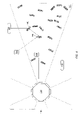
- FIG. 1 shows a first block diagram of a system for wireless communication using robust topology.
- a system 100 includes a wireless communication cell 110 , a base station controller 120 , and one or more sets of customer premises equipment 130 .
- the system 100 also includes a set of more than one sector 111 within the cell 110 , a set of zero or more access points 140 within each sector 111 , and a set of packets 150 sent among the elements of the system 100 .
- the wireless communication cell 110 includes a generally hexagon-shaped region of local surface area, such as might be found in a metropolitan region. Use of generally hexagon-shaped regions is known in the art of wireless communication because they are able to tile a local region with substantially no gaps. However, although in a preferred embodiment the wireless communication cell 110 includes a generally hexagon-shaped region, there is no particular requirement for using that particular shape; in alternative embodiments it may be useful to provide another shape or tiling of the local surface area.
- the base station controller 120 includes a processor, program and data memory, mass storage, and one or more antennas for sending or receiving information using wireless communication techniques.
- each set of customer premises equipment 130 includes a processor, program and data memory, mass storage, and one or more antennas for sending or receiving information using wireless communication techniques.
- Communication among devices within the wireless communication cell 110 is conducted on one-to-one basis between each set of customer premises equipment 130 and the base station controller 120 .
- the base station controller 120 communicates with each set of customer premises equipment 130
- each set of customer premises equipment 130 communicates with the base station controller 120 .
- Customer premises equipment 130 do not communicate directly with other customer premises equipment 130 .
- Communication between the base station controller 120 and each set of customer premises equipment 130 is conducted using a time division duplex technique, in which time duration is are divided into individual frames, each one of which includes a “downstream” portion and an “upstream” portion.
- the base station controller 120 controls tranmissions for both upstream and downstream directions, without specific requests from the customer premises equipment 130 .
- the base station controller 120 transmits, thus sending information to one or more sets of customer premises equipment 130 .
- the base station controller automatically allocates slots for upstream re-transmission. This occurs in the absence of an explicit request for a slot from the customer premises equipment 130 .
- Particular aspects of each frame are described in the Incorporated Disclosures. Time division duplex techniques are known in the art of wireless communication.
- each access point 140 includes a reflector 141 .
- Reflectors are known in the art of wireless communication.
- Each packet 150 sent from the base station controller 120 to the customer premises equipment 130 can be sent line-of-sight to an access point 140 , which can include a reflector 141 , rather than line-of-sight from the base station controller 120 to the customer premises equipment 130 .
- the reflector 141 at the access point 140 causes the electromagnetic signal carrying the packet 150 to be reflected from a first outbound path 151 to a second outbound path 152 , so that the packet 150 reaches the customer premises equipment 130 in better form than using a line-of-sight path between the base station controller 120 to the customer premises equipment 130 .
- each packet 150 sent from the customer premises equipment 130 to the base station controller 120 can be sent line-of-sight to an access point 140 , which can include a reflector 141 , rather than line-of-sight from the customer premises equipment 130 to the base station controller 120 .
- the reflector 141 at the access point 140 causes the electromagnetic signal carrying the packet 150 to be reflected from a first inbound path 153 to a second inbound path 154 , so that the packet 150 reaches the base station controller 120 in better form than using a line-of-sight path between the customer premises equipment 130 to the base station controller 120 .
- FIG. 2 shows a second block diagram of a system for wireless communication using robust topology.
- each access point 140 includes a repeater 142 .
- Repeaters are known in the art of wireless communication.
- Each repeater 142 includes a reconditioning element 143 , such as including amplifiers and noise-removal circuits.
- each packet 150 sent from the base station controller 120 to the customer premises equipment 130 can be sent line-of-sight to an access point 140 , rather than line-of-sight from the base station controller 120 to the customer premises equipment 130 .
- the packet 150 is received, reconditioned (for example, noise is reduced and the signal is re-amplified), and resent from the access point 140 to the destination customer premises equipment 130 , so that the packet 150 reaches the customer premises equipment 130 in better form than using a non-reconditioned path between the base station controller 120 and the customer premises equipment 130 .
- access points 140 using repeaters 142 can also be used for sending packets from the customer premises equipment 130 to the base station controller 120 .
- Access points 140 can include both reflectors 141 and repeaters 142 , and can include combinations thereof, so that a packet 150 can sent line-of-sight to an access point 140 , reconditioned at that access point 140 using a repeater 142 or variant thereof, and resent line-of-sight to its destination (either the base station controller 120 or the customer premises equipment 130 ).
- FIG. 3 shows a third block diagram of a system for wireless communication using robust topology.
- each access point 140 includes a routing or switching device 143 operative within a sector 111 or within a cell 110 .
- Routing or switching devices 143 are known in the art of communication networks.
- each packet 150 sent from the base station controller 120 to the customer premises equipment 130 can be sent line-of-sight to an access point 140 , rather than line-of-sight from the base station controller 120 to the customer premises equipment 130 .
- the packet 150 is received, routed (for example, the destination customer premises equipment 130 is determined and the packet 150 is resent line-of-sight to that destination customer premises equipment 130 ), and resent from the access point 140 to the destination customer premises equipment 130 , so that the packet 150 reaches the customer premises equipment 130 in better form than using a non-routed path between the base station controller 120 and the customer premises equipment 130 .
- access points 140 using routing or switching devices 143 can also be used for sending packets from the customer premises equipment 130 to the base station controller 120 .
- Access points 140 can include any one of reflectors 141 , repeaters 142 , and routing or switching devices 143 , and can include combinations thereof, so that a packet 150 can sent line-of-sight to an access point 140 , routed or switched at that access point 140 using a routing or switching device 143 or variant thereof, reconditioned at that access point 140 using a repeater 142 or variant thereof, and resent line-of-sight to its destination (either the base station controller 120 or the customer premises equipment 130 ).
- routing or switching devices 143 can be used to enforce restrictions on communication between the base station controller 120 and the customer premises equipment 130 , using either ACL (access control list) restrictions, QoS (quality of service) restrictions, or other restrictions known in the art of communication networks.
- ACL access control list
- QoS quality of service
- FIG. 4 shows a fourth block diagram of a system for wireless communication using robust topology.
- each access point 140 includes a routing or switching devices 143 operative within a sector 111 or within a cell 110 .
- each packet 150 sent from the base station controller 120 to the customer premises equipment 130 can be sent line-of-sight to an access point 140 , rather than line-of-sight from the base station controller 120 to the customer premises equipment 130 .
- the packet 150 is received, routed (for example, the destination customer premises equipment 130 is determined and the packet 150 is resent line-of-sight to a second access point 140 ), and resent from the access point 140 to that second access point 140 .
- the packet 150 is again received, routed (for example, the destination customer premises equipment 130 is determined and the packet 150 is resent line-of-sight to the destination customer premises equipment 130 ), so that the packet 150 reaches the customer premises equipment 130 in better form than using a non-routed path between the base station controller 120 and the customer premises equipment 130 .
- access points 140 using routing or switching devices 143 can also be used for sending packets from the customer premises equipment 130 to the base station controller 120 , by way of intermediate access points 140 (whether including routing or switching devices 143 or not).
- FIG. 5 shows a fifth block diagram of a system for wireless communication using robust topology.
- each access point 140 includes a routing or switching devices 143 operative within a sector 111 or within a cell 110 .
- those access points 140 including routing or switching devices 143 can route or switch packets 150 among themselves, so as to route or switch packets 150 from the base station controller 120 to a set of intermediate access points 140 to the customer premises equipment 130 .
- Multi-hop routing of packets 150 is known in the art of communication networks.
- the packet 150 is received, routed, and resent from the access point 140 to a next hop. From the next hop, the process is repeated, until the packet 150 is sent line-of-sight to the customer premises equipment 130 , and thus reaches the customer premises equipment 130 in better form than using a non-routed path between the base station controller 120 and the customer premises equipment 130 .
- each access point 140 includes a routing or switching device 143 capable of performing at least some of the following functions:
- Routing and switching devices 143 can also be configured so as to route or switch only within a single sector 111 within a cell 110 , or to route or switch among multiple sectors 111 within a cell 110 .
- the addition of access points 140 within a cell 110 allows the base station controller 120 to add additional capacity for sending and receiving messages in conjunction with customer premises equipment 130 .
- the set of access points 140 (using reflectors 141 , repeaters 142 , or routing or switching devices 143 ) can form a mesh network in which messages are routed between the base station controller 120 and customer premises equipment 130 , using the set of access points 140 as a communication sub-network.
- the communication sub-network is thus simultaneously (1) a distributed network of intermediate nodes in a switching network, and (2) a centralized switching system under control of the base station controller 120 .
- the set of access points 140 each operate independently to perform routing and switching (possibly including other aspects of routing and switching, such as scheduling, quality of service guarantees, and flow management), while the base station controller 120 controls the PHY and MAC parameters (as shown in the Incorporated Disclosures) of each of the access points 140 .
- the base station controller 120 can control each of the access points 140 separately, or can determine global parameters for use within a cell 110 or sector within a cell 110 .
- each access point 140 can perform some or all of the functions of the base station controller 120 , only limited to a portion of the cell 110 .
- the base station controller 120 and the set of access points 140 within that sector can cooperate to control traffic, so as to form a micro-cell within the cell 110 .
- any one micro-cell must be entirely within a single sector; micro-cells can span portions of multiple sectors or even portions of multiple cells 110 .
- This also allows the base station controller 120 and the set of access points 140 to cooperatively maintain a multi-tier cellular architecture, with each micro-cell each controlled by an associated access point 140 and cells 110 including multiple micro-cells controlled by the base station controller 120 .
- the addition of access points 140 within a cell 110 allows the base station controller 120 to add incremental additional capacity for sending and receiving messages and controlling the flow of messages within the cell 110 . This enables the wireless system to grow in incremental steps, rather than large jumps in capacity, so as to create a “pay as you grow” deployable system. There is no particular requirement that the addition of access points 140 within a cell 110 requires the base station controller 120 itself to have additional capacity or functionality.
- communication paths must be line of sight.
- electromagnetic communication is line of sight
- electromagnetic communication it is also possible for electromagnetic communication to include non line of sight components.
- a first example is differential penetration of barriers at different frequencies, such as buildings which pose a substantial reflection problem at a first frequency f 1 but do not pose a substantial reflection problem at a second frequency f 2 .
- a second example is refraction of electromagnetic communication at known frequencies so as to obtain a non line of sight path.
- a third example is multipath addition resulting in communication between a first peak and a second peak in a communication standing wave.
- the base station controller 120 can thus control QOS between the base station controller 120 and customer premises equipment 130 , either by (1) controlling specific PHY and MAC parameters for direct communication, (2) controlling specific PHY and MAC parameters for indirect communication using access points 140 , or (3) selection of the number and location of access points 140 for indirect communication with customer premises equipment 130 .
- the base station controller 120 can choose, instead of a shortest-path strategy, a best-QOS strategy for routing messages using access points 140 to customer premises equipment 130 .
- the base station controller 120 can be located in many additional locations, as can customer premises equipment 130 . Moreover, since the base station controller 120 controls the PHY, MAC and other parameters, it is easier to deploy the wireless communication system and obtain acceptable communication between the base station controller 120 and customer premises equipment 130 using access points 140 .
- access points 140 within a cell 110 makes it easier to use the wireless communication system in conjunction with requirements for QOS and flow management. Since the base station controller 120 controls the PHY, MAC and other parameters, it is easier to manage the wireless communication system for QOS and flow management and obtain acceptable communication between the base station controller 120 and customer premises equipment 130 using access points 140 .
- the invention has general applicability to various fields of use, not necessarily related to the services described above.
- these fields of use can include one or more of, or some combination of, the following:
Abstract
Description
-
- U.S. patent application Ser. No. 09/475,642, Express Mail Mailing No. EL524 780 018 US, filed Dec. 30, 1999, in the name of of Varma, Subir, Ngo, Khuong, Fuentes, Jean, Truong, Paul, and Majidi-Ahy, Reza, titled “Adaptive Link Layer for Point to Multipoint Communication System.”
- U.S. patent application Ser. No. 09/475,716, Express Mail Mailing No. EL 524 780 021 US, filed Dec. 30, 1999, in the name of Majidi-Ahy, Reza, Hakim, Joseph, and Varma, Subir, titled “Integrated Self-Optimizing Multi-Parameter and Multi-Variable Point to MultiPoint Communication System.”
-
- access point in general, a device for performing message forwarding (either passively or actively) within a wireless communication cell. There is no particular requirement that an access point must be a single device; in alternative embodiments, the access points can each include a portion of a single device, a combination of multiple devices, or some hybrid thereof. Access points are sometimes referred to herein as “broadband” access points, to indicate their generic ability to handle broadband communication instead of, or in addition to, narrowband communcation.
- base station controller—in general, a device for performing coordination and control for a wireless communication cell. There is no particular requirement that the base station controller must be a single device; in alternative embodiments, the base station controller can include a portion of a single device, a combination of multiple devices, or some hybrid thereof.
- cell—in general, a region associated with a base station controller in which customer premises equipment communicate with the base station controller and in which the base station controller exercises control over communication parameters. Although in a preferred embodiment, cells are each contiguous and compact, there is no particular requirement for either property; cells may include non-contiguous sub-regions and are not necessarily compact.
- communication link—in general, an element for sending information from a sender to a recipient. Although in a preferred embodiment the communication links referred to are generally wireless line of sight point-to-point communication links, there is no particular requirement that they are so restricted.
- customer premises equipment—in general, a device for performing communication processes and tasks at a customer location, and operating in conjunction with the base station controller within a wireless communication cell. There is no particular requirement that the customer premises equipment must be a single device; in alternative embodiments, the customer premises equipment can include a portion of a single device, a combination of multiple devices, or some hybrid thereof.
- MAC parameters—in general, with reference to a wireless communication link, a set of characteristics or parameters relating to media access control of a communication link. For example, MAC parameters can include (a) a number of payload data bytes assigned per message, (b) a frequency of acknowledgement messages and a number of message retransmission attempts, (c) a fraction of the communication link allocated to downstream versus upstream communication, and the like.
- physical parameters—in general, with reference to a wireless communication link, a set of characteristics or parameters relating to physical transmission of information on a communication link. For example, physical characteristics can include (a) a symbol transmission rate, (b) a number of payload data bits assigned per symbol, (c) a number of error detection or correction bits assigned per symbol, and the like.
- propagate or route—in general, to forward a message from a sender toward a destination using an intermediate point, such as an intermediate reflector, repeater, or routing or switching element
- sector—in general, a portion of a cell that is not the entire cell. For example, a cell can be divided into multiple sectors in response to an angle of direction or a distance from the base station controller. There is no particular requirement that sectors must be disjoint; they may be overlapping.
- wireless communication system—in general, a communication system including at least one communication link that uses wireless communication techniques.
- wireless transport layer—in general, a set of protocols and protocol parameters for sending and receiving information using wireless transport. In a preferred embodiment, the wireless transport layer is part of a multilayer systems architecture, in which the wireless transport layer is built using a physical transport layer, and the wireless transport layer is used by a logical transport layer such as IP.
-
- IP routing—routing or switching
devices 143 can routepackets 150 using IP layer routing or switching - MAC routing—routing or switching
devices 143 can routepackets 150 using MAC layer routing or switching - Re-Adaptation—routing or switching
devices 143 can re-adaptpackets 150, such as breakingpackets 150 into smaller units and collecting smaller units intolarger packets 150 - Mini-Scheduler—routing or switching
devices 143 can include a scheduling function for determining whichpackets 150 to give priority to in routing, re-adaptation, and resending
- IP routing—routing or switching
-
- The invention is applicable to other forms of wireless communication, such as code division multiple access (CDMA, also known as spread spectrum communication), frequency division multiple access (FDMA), space division multiple access (SDMA), time division multiple access (TDMA), and combinations thereof;
- The invention is applicable to wireline (that is, non-wireless) communication, in which now can be achieved from dynamically adjusting communication parameters, such as physical parameters or MAC parameters. For example, the invention can be generalized to wireline communication using modems in which equalization parameters are to be dynamically adjusted.
- The invention is applicable to other wireless communication systems, such as satellite communication systems and (microwave tower or other) point to point transmission systems.
- The invention is applicable to both fixed wireless communication systems, in which customer premises equipment do not move relative to the
base station controller 120, and to mobile wireless communication systems, and which customer premises equipment move substantially relative to thebase station controller 120.
Claims (19)
Priority Applications (8)
| Application Number | Priority Date | Filing Date | Title |
|---|---|---|---|
| US09/540,674 US7158784B1 (en) | 2000-03-31 | 2000-03-31 | Robust topology wireless communication using broadband access points |
| AU2001249666A AU2001249666B2 (en) | 2000-03-31 | 2001-03-30 | Robust topology wireless communication using broadband access points |
| PCT/US2001/010300 WO2001076289A2 (en) | 2000-03-31 | 2001-03-30 | Robust topology wireless communication using broadband access points |
| KR1020027013009A KR100730353B1 (en) | 2000-03-31 | 2001-03-30 | Robust topology wireless communication using broadband access points |
| AU4966601A AU4966601A (en) | 2000-03-31 | 2001-03-30 | Robust topology wireless communication using broadband access points |
| EP01922916A EP1269777A2 (en) | 2000-03-31 | 2001-03-30 | Robust topology wireless communication using broadband access points |
| JP2001573830A JP4779130B2 (en) | 2000-03-31 | 2001-03-30 | Robust wireless communication using broadband access points |
| US11/645,224 US20070184828A1 (en) | 2000-03-31 | 2006-12-22 | Robust topology wireless communication using broadband access points |
Applications Claiming Priority (1)
| Application Number | Priority Date | Filing Date | Title |
|---|---|---|---|
| US09/540,674 US7158784B1 (en) | 2000-03-31 | 2000-03-31 | Robust topology wireless communication using broadband access points |
Related Child Applications (1)
| Application Number | Title | Priority Date | Filing Date |
|---|---|---|---|
| US11/645,224 Continuation US20070184828A1 (en) | 2000-03-31 | 2006-12-22 | Robust topology wireless communication using broadband access points |
Publications (1)
| Publication Number | Publication Date |
|---|---|
| US7158784B1 true US7158784B1 (en) | 2007-01-02 |
Family
ID=24156462
Family Applications (2)
| Application Number | Title | Priority Date | Filing Date |
|---|---|---|---|
| US09/540,674 Expired - Lifetime US7158784B1 (en) | 2000-03-31 | 2000-03-31 | Robust topology wireless communication using broadband access points |
| US11/645,224 Abandoned US20070184828A1 (en) | 2000-03-31 | 2006-12-22 | Robust topology wireless communication using broadband access points |
Family Applications After (1)
| Application Number | Title | Priority Date | Filing Date |
|---|---|---|---|
| US11/645,224 Abandoned US20070184828A1 (en) | 2000-03-31 | 2006-12-22 | Robust topology wireless communication using broadband access points |
Country Status (6)
| Country | Link |
|---|---|
| US (2) | US7158784B1 (en) |
| EP (1) | EP1269777A2 (en) |
| JP (1) | JP4779130B2 (en) |
| KR (1) | KR100730353B1 (en) |
| AU (2) | AU2001249666B2 (en) |
| WO (1) | WO2001076289A2 (en) |
Cited By (3)
| Publication number | Priority date | Publication date | Assignee | Title |
|---|---|---|---|---|
| US20050068902A1 (en) * | 2003-07-09 | 2005-03-31 | Kamlesh Rath | Scalable broadband wireless mesh access network |
| US20080316986A1 (en) * | 2006-01-31 | 2008-12-25 | Koninklijke Philips Electronics N. V. | Remote Antenna for Wireless Access Point |
| US20120180094A1 (en) * | 2000-10-03 | 2012-07-12 | At&T Intellectual Property Ii, Lp | Intra-premises wireless broadband service using lumped and distributed wireless radiation from cable source input |
Families Citing this family (30)
| Publication number | Priority date | Publication date | Assignee | Title |
|---|---|---|---|---|
| US7158784B1 (en) | 2000-03-31 | 2007-01-02 | Aperto Networks, Inc. | Robust topology wireless communication using broadband access points |
| GB0200237D0 (en) * | 2002-01-07 | 2002-02-20 | Imec Inter Uni Micro Electr | Wireless cellular network architecture |
| EP1537744A1 (en) * | 2002-09-06 | 2005-06-08 | Koninklijke Philips Electronics N.V. | Parameter encoding for an improved atsc dtv system |
| US20040066787A1 (en) * | 2002-10-03 | 2004-04-08 | Agere Systems Inc. | Centralized concentrator and method of distributing wireless communications in a computer network |
| GB2440980A (en) | 2006-08-18 | 2008-02-20 | Fujitsu Ltd | Wireless multi-hop communication system |
| GB2443466A (en) * | 2006-11-06 | 2008-05-07 | Fujitsu Ltd | Relay station for multi-hop communication system |
| GB2440981A (en) | 2006-08-18 | 2008-02-20 | Fujitsu Ltd | Wireless multi-hop communication system |
| GB2440986A (en) | 2006-08-18 | 2008-02-20 | Fujitsu Ltd | Wireless multi-hop communication system |
| GB2440984A (en) | 2006-08-18 | 2008-02-20 | Fujitsu Ltd | Wireless multi-hop communication system |
| GB2440985A (en) | 2006-08-18 | 2008-02-20 | Fujitsu Ltd | Wireless multi-hop communication system |
| EP2136587A3 (en) | 2006-08-18 | 2012-05-02 | Fujitsu Limited | communication systems |
| GB2440982A (en) | 2006-08-18 | 2008-02-20 | Fujitsu Ltd | Wireless multi-hop communication system |
| GB2441574A (en) | 2006-09-08 | 2008-03-12 | Fujitsu Ltd | Network entry to a multi-hop wireless communication system |
| GB2442782A (en) | 2006-10-13 | 2008-04-16 | Fujitsu Ltd | Wireless communication systems |
| GB2442783A (en) | 2006-10-13 | 2008-04-16 | Fujitsu Ltd | Wireless communication systems |
| GB2443465A (en) | 2006-11-06 | 2008-05-07 | Fujitsu Ltd | Communication systems |
| FR2939268B1 (en) * | 2008-11-28 | 2011-06-17 | Canon Kk | METHOD FOR DETERMINING COMMUNICATION PATHS IN A WIRELESS COMMUNICATION NETWORK, COMPUTER PROGRAM PRODUCT, STORAGE MEANS, AND CORRESPONDING DEVICES |
| US10425905B1 (en) * | 2018-03-19 | 2019-09-24 | Pivotal Commware, Inc. | Communication of wireless signals through physical barriers |
| US10862545B2 (en) | 2018-07-30 | 2020-12-08 | Pivotal Commware, Inc. | Distributed antenna networks for wireless communication by wireless devices |
| US10522897B1 (en) | 2019-02-05 | 2019-12-31 | Pivotal Commware, Inc. | Thermal compensation for a holographic beam forming antenna |
| US10468767B1 (en) | 2019-02-20 | 2019-11-05 | Pivotal Commware, Inc. | Switchable patch antenna |
| US10734736B1 (en) | 2020-01-03 | 2020-08-04 | Pivotal Commware, Inc. | Dual polarization patch antenna system |
| US11069975B1 (en) | 2020-04-13 | 2021-07-20 | Pivotal Commware, Inc. | Aimable beam antenna system |
| KR20230017280A (en) | 2020-05-27 | 2023-02-03 | 피보탈 컴웨어 인코포레이티드 | RF signal repeater device management for 5G wireless networks |
| WO2022056024A1 (en) | 2020-09-08 | 2022-03-17 | Pivotal Commware, Inc. | Installation and activation of rf communication devices for wireless networks |
| US11843955B2 (en) | 2021-01-15 | 2023-12-12 | Pivotal Commware, Inc. | Installation of repeaters for a millimeter wave communications network |
| JP2024505881A (en) | 2021-01-26 | 2024-02-08 | ピヴォタル コムウェア インコーポレイテッド | smart repeater system |
| US11451287B1 (en) | 2021-03-16 | 2022-09-20 | Pivotal Commware, Inc. | Multipath filtering for wireless RF signals |
| CA3224854A1 (en) | 2021-07-07 | 2023-01-12 | Pivotal Commware, Inc. | Multipath repeater systems |
| US11937199B2 (en) | 2022-04-18 | 2024-03-19 | Pivotal Commware, Inc. | Time-division-duplex repeaters with global navigation satellite system timing recovery |
Citations (37)
| Publication number | Priority date | Publication date | Assignee | Title |
|---|---|---|---|---|
| US5243595A (en) * | 1990-01-30 | 1993-09-07 | Johnson Service Company | Combined connectionless and connection-oriented network control system |
| US5479400A (en) | 1994-06-06 | 1995-12-26 | Metricom, Inc. | Transceiver sharing between access and backhaul in a wireless digital communication system |
| US5546397A (en) | 1993-12-20 | 1996-08-13 | Norand Corporation | High reliability access point for wireless local area network |
| US5553316A (en) | 1992-07-03 | 1996-09-03 | Ncr Corporation | Power control method in a wireless communication system |
| US5592491A (en) * | 1992-10-26 | 1997-01-07 | Eon Corporation | Wireless modem |
| WO1997017768A1 (en) | 1995-11-10 | 1997-05-15 | Ionica International Limited | Method and apparatus for power control in a telephone system |
| US5657325A (en) | 1995-03-31 | 1997-08-12 | Lucent Technologies Inc. | Transmitter and method for transmitting information packets with incremental redundancy |
| US5850593A (en) * | 1994-07-13 | 1998-12-15 | Nec Corporation | Mobile communication for a mobile station near or outside a service area of a base station |
| WO1998059523A2 (en) | 1997-06-20 | 1998-12-30 | Tantivy Communications, Inc. | Dynamic bandwidth allocation to transmit a wireless protocol across a code division multiple access (cdma) radio link |
| DE19728469A1 (en) | 1997-07-03 | 1999-01-07 | Siemens Ag | Method and arrangement for coding digital data |
| US5883884A (en) * | 1996-04-22 | 1999-03-16 | Roger F. Atkinson | Wireless digital communication system having hierarchical wireless repeaters with autonomous hand-off |
| WO1999014975A2 (en) | 1997-09-16 | 1999-03-25 | Qualcomm Incorporated | Channel structure for communication systems |
| US5896373A (en) * | 1996-02-22 | 1999-04-20 | Nokia Mobile Phones, Ltd. | Method for executing handover in a radio extension of an ATM network |
| WO1999023844A2 (en) | 1997-11-03 | 1999-05-14 | Qualcomm Incorporated | Method and apparatus for high rate packet data transmission |
| US5907555A (en) | 1995-10-18 | 1999-05-25 | Telefonaktiebolaget Lm Ericsson | Method for compensating for time dispersion in a communication system |
| US5918176A (en) | 1996-05-23 | 1999-06-29 | Motorola, Inc. | Method and apparatus for controlling link quality in a wireless communication system |
| US5926761A (en) | 1996-06-11 | 1999-07-20 | Motorola, Inc. | Method and apparatus for mitigating the effects of interference in a wireless communication system |
| US5945948A (en) * | 1996-09-03 | 1999-08-31 | Motorola, Inc. | Method and apparatus for location finding in a communication system |
| WO1999044341A1 (en) | 1998-02-24 | 1999-09-02 | Tantivy Communications | Dynamic frame size setting for multichannel transmission |
| US5991345A (en) * | 1995-09-22 | 1999-11-23 | Qualcomm Incorporated | Method and apparatus for diversity enhancement using pseudo-multipath signals |
| US6006073A (en) | 1996-11-09 | 1999-12-21 | Robert Bosch Gmbh | Apparatus and method for improvement of transmission quality in a point-to-multipoint radio transmission system |
| US6049533A (en) * | 1995-10-04 | 2000-04-11 | Aironet Wireless Communications, Inc. | Network communication system with information rerouting capabilities |
| US6122513A (en) * | 1997-11-06 | 2000-09-19 | Nortel Networks Corporation | Method for extending hard-handoff boundaries within a mobile telephone communications network |
| US6141533A (en) * | 1997-11-13 | 2000-10-31 | Motorola, Inc. | Method and apparatus for a mobile repeater |
| US6212387B1 (en) * | 1995-10-18 | 2001-04-03 | Sc-Wireless Inc. | Method and apparatus for collector arrays of directional antennas co-located with zone managers in wireless communications systems |
| US6246861B1 (en) * | 1997-11-06 | 2001-06-12 | Telecommunications Research Lab. | Cellular telephone location system |
| WO2001050669A1 (en) | 1999-12-30 | 2001-07-12 | Aperto Networks, Inc. | Self-optimizing multi-variable point to multipoint communication system |
| WO2001050633A1 (en) | 1999-12-30 | 2001-07-12 | Aperto Networks, Inc. | Adaptive link layer for point to multipoint communication system |
| AU2496601A (en) | 2000-01-05 | 2001-07-16 | John Unsworth | Variable shape guide apparatus |
| US6292651B1 (en) * | 1995-02-06 | 2001-09-18 | Adc Telecommunications, Inc. | Communication system with multicarrier transport distribution network between a head end terminal and remote units |
| WO2001076289A2 (en) | 2000-03-31 | 2001-10-11 | Aperto Networks, Inc. | Robust topology wireless communication using broadband access points |
| US6317594B1 (en) * | 1996-09-27 | 2001-11-13 | Openwave Technologies Inc. | System and method for providing data to a wireless device upon detection of activity of the device on a wireless network |
| WO2002013447A2 (en) | 2000-07-21 | 2002-02-14 | Aperto Networks, Inc. | Integrated, self-optimizing, multi-parameter/multi-variable point-to-multipoint communication system (ii) |
| US6353729B1 (en) * | 1997-11-14 | 2002-03-05 | Nortel Networks Limited | Using an RF repeater in CDMA applications to combat interference caused by a non-collocated radio |
| WO2002025856A2 (en) | 2000-09-20 | 2002-03-28 | Aperto Networks, Inc. | Dynamic wireless link adaptation |
| US6584089B1 (en) * | 1997-05-05 | 2003-06-24 | Nokia Mobile Phones Ltd. | Method for scheduling packet data transmission |
| US6603753B1 (en) * | 1999-12-03 | 2003-08-05 | Lucent Technologies Inc. | Down-link transmission inter-cell scheduling in CDMA data networks |
Family Cites Families (9)
| Publication number | Priority date | Publication date | Assignee | Title |
|---|---|---|---|---|
| US4284848A (en) * | 1979-08-01 | 1981-08-18 | Frost Edward G | Switched network telephone subscriber distribution system |
| JP2531374B2 (en) * | 1993-11-29 | 1996-09-04 | 日本電気株式会社 | Mobile communication system |
| MY123040A (en) * | 1994-12-19 | 2006-05-31 | Salbu Res And Dev Proprietary Ltd | Multi-hop packet radio networks |
| US5787111A (en) * | 1996-05-28 | 1998-07-28 | Mci Communications Corporation | Transportable communication system |
| JPH1132072A (en) * | 1997-07-11 | 1999-02-02 | Nippon Telegr & Teleph Corp <Ntt> | Radio packet path determination method in radio network |
| JP2000049690A (en) * | 1998-07-31 | 2000-02-18 | Nec Yonezawa Ltd | Portable telephone and repeating method |
| JP2000083024A (en) * | 1998-09-04 | 2000-03-21 | Nippon Telegr & Teleph Corp <Ntt> | Electronic file transferring method and storage medium recording program of this method |
| US6831902B1 (en) * | 1999-09-08 | 2004-12-14 | Qwest Communications International, Inc. | Routing information packets in a distributed network |
| US6885868B1 (en) * | 1999-09-30 | 2005-04-26 | Nortel Networks Limited | Fair packet scheduler and scheduling method for packet data radio |
-
2000
- 2000-03-31 US US09/540,674 patent/US7158784B1/en not_active Expired - Lifetime
-
2001
- 2001-03-30 WO PCT/US2001/010300 patent/WO2001076289A2/en active IP Right Grant
- 2001-03-30 JP JP2001573830A patent/JP4779130B2/en not_active Expired - Fee Related
- 2001-03-30 AU AU2001249666A patent/AU2001249666B2/en not_active Ceased
- 2001-03-30 AU AU4966601A patent/AU4966601A/en active Pending
- 2001-03-30 EP EP01922916A patent/EP1269777A2/en not_active Withdrawn
- 2001-03-30 KR KR1020027013009A patent/KR100730353B1/en not_active IP Right Cessation
-
2006
- 2006-12-22 US US11/645,224 patent/US20070184828A1/en not_active Abandoned
Patent Citations (38)
| Publication number | Priority date | Publication date | Assignee | Title |
|---|---|---|---|---|
| US5243595A (en) * | 1990-01-30 | 1993-09-07 | Johnson Service Company | Combined connectionless and connection-oriented network control system |
| US5553316A (en) | 1992-07-03 | 1996-09-03 | Ncr Corporation | Power control method in a wireless communication system |
| US5592491A (en) * | 1992-10-26 | 1997-01-07 | Eon Corporation | Wireless modem |
| US5546397A (en) | 1993-12-20 | 1996-08-13 | Norand Corporation | High reliability access point for wireless local area network |
| US5479400A (en) | 1994-06-06 | 1995-12-26 | Metricom, Inc. | Transceiver sharing between access and backhaul in a wireless digital communication system |
| US5850593A (en) * | 1994-07-13 | 1998-12-15 | Nec Corporation | Mobile communication for a mobile station near or outside a service area of a base station |
| US6292651B1 (en) * | 1995-02-06 | 2001-09-18 | Adc Telecommunications, Inc. | Communication system with multicarrier transport distribution network between a head end terminal and remote units |
| US5657325A (en) | 1995-03-31 | 1997-08-12 | Lucent Technologies Inc. | Transmitter and method for transmitting information packets with incremental redundancy |
| US5991345A (en) * | 1995-09-22 | 1999-11-23 | Qualcomm Incorporated | Method and apparatus for diversity enhancement using pseudo-multipath signals |
| US6049533A (en) * | 1995-10-04 | 2000-04-11 | Aironet Wireless Communications, Inc. | Network communication system with information rerouting capabilities |
| US6212387B1 (en) * | 1995-10-18 | 2001-04-03 | Sc-Wireless Inc. | Method and apparatus for collector arrays of directional antennas co-located with zone managers in wireless communications systems |
| US5907555A (en) | 1995-10-18 | 1999-05-25 | Telefonaktiebolaget Lm Ericsson | Method for compensating for time dispersion in a communication system |
| WO1997017768A1 (en) | 1995-11-10 | 1997-05-15 | Ionica International Limited | Method and apparatus for power control in a telephone system |
| US5896373A (en) * | 1996-02-22 | 1999-04-20 | Nokia Mobile Phones, Ltd. | Method for executing handover in a radio extension of an ATM network |
| US5883884A (en) * | 1996-04-22 | 1999-03-16 | Roger F. Atkinson | Wireless digital communication system having hierarchical wireless repeaters with autonomous hand-off |
| US5918176A (en) | 1996-05-23 | 1999-06-29 | Motorola, Inc. | Method and apparatus for controlling link quality in a wireless communication system |
| US5926761A (en) | 1996-06-11 | 1999-07-20 | Motorola, Inc. | Method and apparatus for mitigating the effects of interference in a wireless communication system |
| US5945948A (en) * | 1996-09-03 | 1999-08-31 | Motorola, Inc. | Method and apparatus for location finding in a communication system |
| US6317594B1 (en) * | 1996-09-27 | 2001-11-13 | Openwave Technologies Inc. | System and method for providing data to a wireless device upon detection of activity of the device on a wireless network |
| US6006073A (en) | 1996-11-09 | 1999-12-21 | Robert Bosch Gmbh | Apparatus and method for improvement of transmission quality in a point-to-multipoint radio transmission system |
| US6584089B1 (en) * | 1997-05-05 | 2003-06-24 | Nokia Mobile Phones Ltd. | Method for scheduling packet data transmission |
| WO1998059523A2 (en) | 1997-06-20 | 1998-12-30 | Tantivy Communications, Inc. | Dynamic bandwidth allocation to transmit a wireless protocol across a code division multiple access (cdma) radio link |
| DE19728469A1 (en) | 1997-07-03 | 1999-01-07 | Siemens Ag | Method and arrangement for coding digital data |
| WO1999001959A2 (en) | 1997-07-03 | 1999-01-14 | Siemens Aktiengesellschaft | Method and system for coding digital data |
| WO1999014975A2 (en) | 1997-09-16 | 1999-03-25 | Qualcomm Incorporated | Channel structure for communication systems |
| WO1999023844A2 (en) | 1997-11-03 | 1999-05-14 | Qualcomm Incorporated | Method and apparatus for high rate packet data transmission |
| US6246861B1 (en) * | 1997-11-06 | 2001-06-12 | Telecommunications Research Lab. | Cellular telephone location system |
| US6122513A (en) * | 1997-11-06 | 2000-09-19 | Nortel Networks Corporation | Method for extending hard-handoff boundaries within a mobile telephone communications network |
| US6141533A (en) * | 1997-11-13 | 2000-10-31 | Motorola, Inc. | Method and apparatus for a mobile repeater |
| US6353729B1 (en) * | 1997-11-14 | 2002-03-05 | Nortel Networks Limited | Using an RF repeater in CDMA applications to combat interference caused by a non-collocated radio |
| WO1999044341A1 (en) | 1998-02-24 | 1999-09-02 | Tantivy Communications | Dynamic frame size setting for multichannel transmission |
| US6603753B1 (en) * | 1999-12-03 | 2003-08-05 | Lucent Technologies Inc. | Down-link transmission inter-cell scheduling in CDMA data networks |
| WO2001050669A1 (en) | 1999-12-30 | 2001-07-12 | Aperto Networks, Inc. | Self-optimizing multi-variable point to multipoint communication system |
| WO2001050633A1 (en) | 1999-12-30 | 2001-07-12 | Aperto Networks, Inc. | Adaptive link layer for point to multipoint communication system |
| AU2496601A (en) | 2000-01-05 | 2001-07-16 | John Unsworth | Variable shape guide apparatus |
| WO2001076289A2 (en) | 2000-03-31 | 2001-10-11 | Aperto Networks, Inc. | Robust topology wireless communication using broadband access points |
| WO2002013447A2 (en) | 2000-07-21 | 2002-02-14 | Aperto Networks, Inc. | Integrated, self-optimizing, multi-parameter/multi-variable point-to-multipoint communication system (ii) |
| WO2002025856A2 (en) | 2000-09-20 | 2002-03-28 | Aperto Networks, Inc. | Dynamic wireless link adaptation |
Non-Patent Citations (2)
| Title |
|---|
| Information Sciences Institute. "DARPA Internet Program Protocol Specification," Sep. 1981, pp. 1-45, Information Sciences Institute, University of Southern California, Marina del Rey, USA. |
| Seyhan Civanlar and Bharat T. Doshi. "Self-Healing in Wideband Packet Networks". IEEE Network vol. 4 (Jan. 1990) No. 1, New York, pp. 35-39. XP 000113853. |
Cited By (6)
| Publication number | Priority date | Publication date | Assignee | Title |
|---|---|---|---|---|
| US20120180094A1 (en) * | 2000-10-03 | 2012-07-12 | At&T Intellectual Property Ii, Lp | Intra-premises wireless broadband service using lumped and distributed wireless radiation from cable source input |
| US8660477B2 (en) * | 2000-10-03 | 2014-02-25 | At&T Intellectual Property Ii, Lp. | Intra-premises wireless broadband service using lumped and distributed wireless radiation from cable source input |
| US9264741B2 (en) | 2000-10-03 | 2016-02-16 | At&T Intellectual Property Ii, Lp | Intra-premises wireless broadband service using lumped and distributed wireless radiation from cable source input |
| US10080040B2 (en) | 2000-10-03 | 2018-09-18 | At&T Intellectual Property Ii, L.P. | Intra-premises wireless broadband service using lumped and distributed wireless radiation from cable source input |
| US20050068902A1 (en) * | 2003-07-09 | 2005-03-31 | Kamlesh Rath | Scalable broadband wireless mesh access network |
| US20080316986A1 (en) * | 2006-01-31 | 2008-12-25 | Koninklijke Philips Electronics N. V. | Remote Antenna for Wireless Access Point |
Also Published As
| Publication number | Publication date |
|---|---|
| US20070184828A1 (en) | 2007-08-09 |
| AU4966601A (en) | 2001-10-15 |
| WO2001076289A3 (en) | 2002-01-31 |
| KR100730353B1 (en) | 2007-06-20 |
| EP1269777A2 (en) | 2003-01-02 |
| AU2001249666B2 (en) | 2004-08-26 |
| JP4779130B2 (en) | 2011-09-28 |
| KR20020087449A (en) | 2002-11-22 |
| JP2003530044A (en) | 2003-10-07 |
| WO2001076289A2 (en) | 2001-10-11 |
Similar Documents
| Publication | Publication Date | Title |
|---|---|---|
| US7158784B1 (en) | Robust topology wireless communication using broadband access points | |
| AU2001249666A1 (en) | Robust topology wireless communication using broadband access points | |
| US8750172B2 (en) | Automatic retransmission and error recovery for packet oriented point-to-multipoint communication | |
| US7545765B2 (en) | Multi-user diversity forwarding | |
| JP4526533B2 (en) | Contention transfer with integrated multi-user detection | |
| US8385921B1 (en) | Backhaul aware radio access networks | |
| US7349426B2 (en) | Integrated, self-optimizing, multi-parameter/multi-variable point-to-multipoint communication system [II] | |
| US20060227720A1 (en) | High-capacity scalable integrated wireless backhaul for broadband access networks | |
| US9425985B1 (en) | Protection switching in radio networks | |
| Fujii et al. | Ad-hoc cognitive radio-development to frequency sharing system by using multi-hop network | |
| US6870816B1 (en) | Self-organizing network with decision engine and method | |
| KR20080090352A (en) | Method, wireless communication system, tangible machine-readable medium, and communication apparatus for transmitting downlink hybrid automatic repeat request packets based on a multi-hop relay standard | |
| Fujii et al. | Multi-band ad-hoc cognitive radio for reducing inter system interference | |
| Lee et al. | A cooperative ARQ scheme for multi-hop underwater acoustic sensor networks | |
| US8830906B1 (en) | Integrated quality of service interface for ethernet radio | |
| Schoenen | Multihop Extensions to Cellular Networks—the Benefit of Relaying for LTE | |
| Thangam et al. | A survey on cross-layer based approach for improving TCP performance in multi hop mobile adhoc networks | |
| US8379576B1 (en) | Call admission control systems and methods for wireless networks | |
| Guo et al. | Differentiated cooperative multiple access for multimedia communications over fading wireless networks | |
| Malliga et al. | TCP–AP and LRED over Single and Multiple TCP Flows in Multihop Wireless Channel | |
| Nguyen | A Cooperative Diversity-based Virtual MISO Framework for Multi-hop Wireless Networks | |
| Ramchitra | Performance enhancement in MANET for duo coverage broadcasting | |
| Wysocarski | Routing protocols for frequency-hop wireless networks | |
| Saban et al. | Wireless local loop and packet radio technology for developing communities | |
| Malliga et al. | Impact of Multihop Wireless Channel on TCP-AP with LRED |
Legal Events
| Date | Code | Title | Description |
|---|---|---|---|
| AS | Assignment |
Owner name: APERTO NETWORKS, INC. A CORPORATION OF CALIFORNIA, Free format text: ASSIGNMENT OF ASSIGNORS INTEREST;ASSIGNOR:REZA, MAJIDI-AHY;REEL/FRAME:010625/0951 Effective date: 20000412 |
|
| AS | Assignment |
Owner name: APERTO NETWORKS, INC., CALIFORNIA Free format text: ASSIGNMENT OF ASSIGNORS INTEREST;ASSIGNOR:MAJIDI-AHY, REZA;REEL/FRAME:010938/0568 Effective date: 20000415 |
|
| AS | Assignment |
Owner name: VENTURE BANKING GROUP, A DIVISION OF GREATER BAY B Free format text: SECURITY AGREEMENT;ASSIGNOR:APERTO NETWORKS, INC.;REEL/FRAME:017025/0624 Effective date: 20060106 |
|
| STCF | Information on status: patent grant |
Free format text: PATENTED CASE |
|
| AS | Assignment |
Owner name: APERTO NETWORKS, INC., CALIFORNIA Free format text: RELEASE BY SECURED PARTY;ASSIGNOR:GREATER BAY VENTURE BANKING, A DIVISION OF GREATER BAY BANK, N.A., FORMERLY VENTURE BANKING GROUP, A DIVISION OF GREATER BAY BANK N.A.;REEL/FRAME:019365/0274 Effective date: 20070508 |
|
| AS | Assignment |
Owner name: BRIDGE BANK, NATIONAL ASSOCIATION, CALIFORNIA Free format text: SECURITY AGREEMENT;ASSIGNOR:APERTO NETWORKS, INC.;REEL/FRAME:022380/0779 Effective date: 20081021 |
|
| AS | Assignment |
Owner name: WI-LAN INC.,CANADA Free format text: ASSIGNMENT OF ASSIGNORS INTEREST;ASSIGNOR:APERTO NETWORKS, INC.;REEL/FRAME:024599/0387 Effective date: 20100601 |
|
| FPAY | Fee payment |
Year of fee payment: 4 |
|
| FPAY | Fee payment |
Year of fee payment: 8 |
|
| FEPP | Fee payment procedure |
Free format text: MAINTENANCE FEE REMINDER MAILED (ORIGINAL EVENT CODE: REM.) |
|
| AS | Assignment |
Owner name: MONUMENT BANK OF INTELLECTUAL PROPERTY, LLC, TEXAS Free format text: ASSIGNMENT OF ASSIGNORS INTEREST;ASSIGNOR:WI-LAN INC.;REEL/FRAME:046867/0766 Effective date: 20160209 |
|
| FEPP | Fee payment procedure |
Free format text: 11.5 YR SURCHARGE- LATE PMT W/IN 6 MO, LARGE ENTITY (ORIGINAL EVENT CODE: M1556); ENTITY STATUS OF PATENT OWNER: LARGE ENTITY |
|
| MAFP | Maintenance fee payment |
Free format text: PAYMENT OF MAINTENANCE FEE, 12TH YEAR, LARGE ENTITY (ORIGINAL EVENT CODE: M1553); ENTITY STATUS OF PATENT OWNER: LARGE ENTITY Year of fee payment: 12 |