US7304649B2 - Object region data describing method and object region data creating apparatus - Google Patents
Object region data describing method and object region data creating apparatus Download PDFInfo
- Publication number
- US7304649B2 US7304649B2 US11/189,761 US18976105A US7304649B2 US 7304649 B2 US7304649 B2 US 7304649B2 US 18976105 A US18976105 A US 18976105A US 7304649 B2 US7304649 B2 US 7304649B2
- Authority
- US
- United States
- Prior art keywords
- object region
- data
- trajectory
- approximate
- function
- Prior art date
- Legal status (The legal status is an assumption and is not a legal conclusion. Google has not performed a legal analysis and makes no representation as to the accuracy of the status listed.)
- Expired - Lifetime, expires
Links
Images


Classifications
-
- G—PHYSICS
- G06—COMPUTING; CALCULATING OR COUNTING
- G06T—IMAGE DATA PROCESSING OR GENERATION, IN GENERAL
- G06T7/00—Image analysis
- G06T7/60—Analysis of geometric attributes
-
- G—PHYSICS
- G06—COMPUTING; CALCULATING OR COUNTING
- G06T—IMAGE DATA PROCESSING OR GENERATION, IN GENERAL
- G06T7/00—Image analysis
- G06T7/20—Analysis of motion
- G06T7/246—Analysis of motion using feature-based methods, e.g. the tracking of corners or segments
- G06T7/251—Analysis of motion using feature-based methods, e.g. the tracking of corners or segments involving models
-
- G—PHYSICS
- G06—COMPUTING; CALCULATING OR COUNTING
- G06T—IMAGE DATA PROCESSING OR GENERATION, IN GENERAL
- G06T7/00—Image analysis
- G06T7/20—Analysis of motion
- G06T7/246—Analysis of motion using feature-based methods, e.g. the tracking of corners or segments
-
- G—PHYSICS
- G06—COMPUTING; CALCULATING OR COUNTING
- G06T—IMAGE DATA PROCESSING OR GENERATION, IN GENERAL
- G06T2207/00—Indexing scheme for image analysis or image enhancement
- G06T2207/10—Image acquisition modality
- G06T2207/10016—Video; Image sequence
-
- G—PHYSICS
- G06—COMPUTING; CALCULATING OR COUNTING
- G06T—IMAGE DATA PROCESSING OR GENERATION, IN GENERAL
- G06T2207/00—Indexing scheme for image analysis or image enhancement
- G06T2207/30—Subject of image; Context of image processing
- G06T2207/30236—Traffic on road, railway or crossing
Definitions
- the present invention relates to an object region data describing method of describing information about the object region in a video and an object region data creating apparatus.
- Hyper media are configured such that related information called a hyper link is given in between mediums, such as videos, sounds or texts, to permit mutual reference.
- videos are mainly used, related information has been provided for each object which appears in the video.
- related information text information or the like
- the foregoing structure is a representative example of the hyper media.
- the object in the video is expressed by a frame number or a time stamp of the video, and information for identifying a region in the video which are recorded in video data or recorded as individual data.
- the mask image is a bit map image constituted by giving different pixel values between the inside portion of an identified region and the outside portion of the same.
- a simplest method has an arrangement that a pixel value of “1” is given to the inside portion of the region and “0” is given to the outside portion of the same.
- ⁇ values which are employed in computer graphics are sometimes employed. Since the ⁇ value is usually able to express 256 levels of gray, a portion of the levels is used. The inside portion of the specified region is expressed as 255, while the outside portion of the same is expressed as 0. The latter image is called an ⁇ map.
- the regions in the image are expressed by the mask images, determination whether or not a pixel in a frame is included in the specified region can easily be made by reading the value of the pixel of the mask image and by determining whether the value is 0 or 255.
- the mask image has freedom with which a region can be expressed regardless of the shape of the region and even a discontinuous region can be expressed.
- the mask image must have pixels, the size of which is the same as the size of the original image. Thus, there arises a problem in that the quantity of data cannot be reduced.
- the mask image is frequently compressed.
- the mask image is a binary mask image constituted by 0 and 1
- a process of a binary image can be performed. Therefore, the compression method employed in facsimile machines or the like is frequently employed.
- MPEG-4 in which ISO/IEC MPEG (Moving Picture Experts Group) has been standardized
- an arbitrary shape coding method is employed in which the mask image constituted by 0 and 1 and the mask image using the ⁇ value are compressed.
- the foregoing compression method is a method using motion compensation and capable of improving compression efficiency.
- complex compression and decoding processes are required.
- the mask image or the compressed mask image has usually been employed.
- data for identifying a region is required to permit easy and quick extraction, to be reduced in quantity and to permit easy handling.
- the mask image is not suitable for identifying the object region in the video since it has a large quantity of data.
- the compressed mask image has a drawback in that coding/decodig is complicated and directly accessing to the pixel of a predetermined frame cannot be performed causing handling to become difficult.
- the present invention is directed to method and apparatus that substantially obviates one or more of the problems due to limitations and disadvantages of the related art.
- the invention is directed to an object region data describing method and an object region data creating apparatus which enable the region of a desired object in an image to be described in a small amount of data and facilitate the creation and handling of the data.
- Another object of the invention is to provide an object region data describing method and an object region data creating apparatus which enable an object in an image to be searched for efficiently and effectively.
- a method of describing object region data about an object in video data over a plurality of frames comprising:
- the trajectories being obtained by arranging, in the frames advancing direction, position data about one of the plurality of points and relative position data about remaining points with reference to the one of the plurality of points;
- Another method of describing object region data about an object in video data over a plurality of frames comprising:
- the trajectories being obtained by arranging, in the frames advancing direction, position data about the plurality of points in a reference frame and relative position data about the plurality of points in a succeeding frame with reference to the position data about the plurality of points in the reference frame;
- a further method of describing object region data about an object in video data over a plurality of frames comprising:
- the trajectories being obtained by arranging, in the frames advancing direction, data indicating positions of the plurality of points;
- a still another method of describing object region data about an object in video data over a plurality of frames comprising:
- the trajectories being obtained by arranging, in the frames advancing direction, data indicating positions of the plurality of points;
- a still further method of describing object region data about an object in video data over a plurality of frames comprising:
- the trajectories being obtained by arranging, in the frames advancing direction, data indicating positions of the plurality of points;
- a still further method of describing object region data about an object moving in a panorama image formed by combining a plurality of frames with being overlapped comprising:
- the trajectories being obtained by arranging, in the frames advancing direction, data indicating positions of the plurality of points;
- FIG. 1 shows an object region data creating apparatus according to a first embodiment of the present invention
- FIG. 2 is a flowchart for processing in the object region data creating apparatus according to the first embodiment
- FIGS. 3A , 3 B, and 3 C are diagrams to help schematically explain the process of describing the object region in an image using object region data
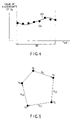
- FIG. 4 is a diagram to help explain an example of finding a function that approximates the value of the X-coordinate of a reference representative point
- FIG. 5 is a diagram to help explain differential vectors for depicting representative points other than the reference representative point
- FIG. 6 is a diagram to help explain an example of finding a function that approximates the values of the X components of the differential vectors for depicting representative points other than the reference representative point;
- FIG. 7 is a flowchart for the process of finding an approximate function from the coordinates of representative points or differential vectors
- FIG. 8 shows an example of the structure of object region data
- FIG. 9 shows an example of the structure of the representative point trajectory data in the object region data
- FIG. 10 is a diagram to help explain another example of differential vectors for depicting representative points other than the reference representative point
- FIGS. 11A and 11B are diagrams to help explain still other examples of differential vectors for depicting representative points other than the reference representative point;
- FIG. 12 is a diagram to help explain an example of differential vectors between frames
- FIG. 13 shows another example of the structure of the object region data
- FIG. 14 is a flowchart for the process of extracting the object region at a give time from the object region data
- FIG. 15 shows an object region data creating apparatus according to a second embodiment of the present invention.
- FIG. 16 shows an example of the structure of the representative point trajectory data in the object region data according to a second embodiment
- FIG. 17 shows still another example of the structure of the object region data
- FIG. 18 shows an example of the data structure of depth information
- FIG. 19 is an illustration to help explain the measurement of positional information in the direction of depth
- FIG. 20 is a flowchart for the process of searching for an object near the specified position
- FIGS. 21A and 21B are illustrations to help explain the measurement of positional information in the direction of depth
- FIG. 22 is a diagram to help explain the measurement of positional information in the direction of depth
- FIG. 23 is a diagram to help explain the measurement of positional information in the direction of depth
- FIG. 24 is a flowchart for the preprocess of determining the time when the moving body exists at the specified distance
- FIG. 25 is a flowchart for the process of determining the time when the moving body exists at the specified distance
- FIGS. 26A , 26 B, and 26 C are illustrations to help explain display flags according to a third embodiment
- FIG. 27 is a diagram to help explain the creation of representative point trajectory data
- FIG. 28 shows still another example of the structure of the object region data
- FIG. 29 shows an example of the structure of the display flag information
- FIG. 30 shows still another example of the structure of the representative point trajectory data in the object region data
- FIG. 31 is a flowchart for the process of searching
- FIGS. 32A , 32 B, and 32 C are diagrams to help explain information about the object passing range according to a fourth embodiment
- FIG. 33 shows an example of the structure of the information about the object passing range
- FIG. 34 shows a still another example of the structure of the information about the object passing range
- FIG. 35 is a flowchart for the process of selecting an object passing the specified coordinate
- FIG. 36 is a flowchart for the procedure for processing by an object region data describing method using mosaicking techniques according to a fifth embodiment
- FIGS. 37A and 37B are diagrams to help explain the object region data describing method using mosaicking techniques
- FIG. 38 shows an example of the structure of the information relating to a coordinate conversion
- FIGS. 39A , 39 B, 39 C, and 39 D are diagrams showing a procedure for describing an object region in a video with object region data according to a fourth embodiment
- FIG. 40 is a diagram showing an example of a process for approximating an object region with an ellipse
- FIG. 41 is a diagram showing an example of a process for detecting a representative point of an approximate ellipse of an object region
- FIG. 42 is a diagram showing an example of the structure of object region data
- FIG. 43 is a diagram showing an example of the structure of data of an approximate figure in object region data
- FIG. 44 is a diagram showing an example of the structure of data of a trajectory of a representative point in data of an approximate figure
- FIG. 45 is a diagram showing another example of the structure of data of an approximate figure in object region data
- FIG. 46 is a diagram showing an example of representative points when the approximate figure is a parallelogram
- FIG. 47 is a diagram showing an example in which the object region in a video is expressed with a plurality of ellipses
- FIG. 48 is a diagram showing an example of the structure of object region data including data of a plurality of approximate figures
- FIGS. 49A , 49 B, and 49 C are diagrams schematically showing another process for describing an object region in a video with object region data
- FIG. 50 is a flowchart showing an example of a procedure for obtaining an approximate rectangle
- FIG. 51 is a diagram showing a state in which an inclined and elongated object is approximated with a non-inclined rectangle
- FIG. 52 is a flowchart showing an example of a procedure for obtaining an approximate ellipse from an approximate rectangle
- FIG. 53 is a diagram showing the first half of another example of the structure of object region data
- FIG. 54 is a diagram showing the second half of the other example of the structure of object region data
- FIG. 55 is a diagram showing a still another example of the structure of object region data
- FIG. 56 is a diagram showing a still further example of the structure of object region data
- FIG. 57 shows an object region data creating apparatus according to a seventh embodiment of the present invention.
- FIG. 58 is a flow chart showing one example of processing procedure in the seventh embodiment.
- FIG. 59 is an explanatory view for one example of a method of calculating an object region optical flow
- FIG. 60 is an explanatory view for another example of the method of calculating an object region optical flow
- FIG. 61 is an explanatory view for an example of expressing a conversion parameter by an approximate temporal function
- FIG. 62 shows one example of an object region data description format if the reference object region is expressed by a bit map
- FIG. 63 shows an example of the constitution of the object region data creating apparatus in the seventh embodiment
- FIG. 64 is a flow chart showing another example of processing procedure in the seventh embodiment.
- FIG. 65 is an explanatory view for a method of making the representative points of an approximate figures of object regions correspond to each other;
- FIG. 66 shows the relationship between the types of approximate figures and conversion models for which conversion parameters can be obtained
- FIG. 67 shows one example of a description format for the object region data if the reference object region is approximated by a figure
- FIG. 68 shows one example of the description format of object region data including sampling information
- FIG. 69 is an explanatory view for a state in which one object is divided into regions having similar movement by an optical flow.
- FIG. 70 shows one example of an object region data description format for describing one object in a plurality of regions.
- FIG. 1 shows the configuration of an object region data creating apparatus (or an object region data converting system) according to the first embodiment of the present invention.
- the object region data creating apparatus comprises a video data storage device 100 , a region extracting device 101 , a region figure approximating device 102 , a figure representative point extracting device 103 , a representative point trajectory function approximating device 104 , and an object region data storage device 106 . It may further comprise a related information storage device 105 .
- FIG. 2 is a flowchart for processing in the object region data creating apparatus.
- the video data storage device 100 which stores video data, is composed of, for example, a hard disk, an optical disk, or a semiconductor memory.
- the region extracting device 101 extracts a partial region of the video data (step S 1 ).
- the partial region is generally the object region, such as a specific person, plant, animal, car, or building, in the image. Any thing in the video may be used as the object region, as long as it can be treated as an object in the video.
- the object may be an independent thing, part of a thing (e.g., the head of a person, the hood of a car, or the entrance of a building), a set of things (e.g., a flock of birds or a school of fish).
- the same object frequently appears on consecutive frames, whereas the region corresponding to the same object often varies from frame to frame mainly because of the movement of the object itself and/or the movement of the camera during shooting.
- the region extracting device 101 is for extracting the object region in each frame according to the movement or transformation of the target object.
- any one of the following methods can be used: a method of manually specifying the region all over the frames, a method of extracting the contour of an object consecutively using a dynamic contour model called Snakes as described in M. Kass, et al., “Snakes: Active contour models,” International Journal of Computer Vision, Vol. 1, No. 4, July, 1988, pp.
- the region figure approximating device 102 uses a specific figure, approximates the object region extracted by the region extracting device 101 (step S 2 ).
- Various types of figure including a rectangle, a circle, an ellipse, and a polygon, can be used.
- the type of figure used in approximation may be determined in advance.
- the type of figure may be specified by the user, using specific units, such as each of the objects to be approximated.
- the type of figure may be selected automatically according to the shape or the like of each of the objects to be approximated.
- the region figure approximating device 102 approximates the region frame by frame each time it receives the result of the extraction at the region extracting device 101 .
- the figure may be approximated using the result of extracting the regions in several frames before and after the present frame.
- changes in the size and position of the approximate figure are smoothed between several frames, which make it possible to smooth the movement or transformation of the approximate figure or make errors in region extraction inconspicuous.
- the size of the approximate figure may differ from frame to frame.
- the figure representative point extracting device 103 extracts representative points depicting the approximate figure outputted from the figure approximating device 102 (step S 3 ). What points are set as representative points depends on what approximate figure is used. For example, when the approximate figure is a rectangle, four or three vertexes can be set as representative points. When the approximate figure is a circle, the center and one point on the circumference or the both ends of the diameter can be set as representative points.
- the vertexes of a circumscribed rectangle for the ellipse may be set as representative points (in this case, too, three of the four vertexes are sufficient) or two foci of the ellipse and one point on the ellipse (e.g., one point on the minor axis) may be set as representative points.
- each vertex has only to be set as a representative point.
- Representative points are extracted in each frame each time the figure approximating device 102 outputs information about the approximate figure for one frame.
- Each representative point is represented by the horizontal coordinate axis X and the vertical coordinate axis Y.
- the representative point trajectory function approximating device 104 approximates a time series of the positions of the representative points extracted at the figure representative point extracting device 103 (or the amounts that enable the points to be determined) and arranged in the frames advancing direction, using a function (or approximate function) of time t (e.g., a time stamp assigned to an image) or frame number f (step S 4 ).
- This function is expressed for each representative point and differs in expression, depending on whether X-coordinate or Y-coordinate are used.
- a straight line or a spline curve may be used as a function representing a representative point trajectory.
- the determined approximate curve (including a straight line) is recorded as object region data according to a specific format in the object region data storage device 106 .
- the related information storage device 105 which is provided if necessary, is for storing information (related information) about the objects appearing in the video data stored in the video data storage device 100 and pointer information (including addresses in which related information has been recorded, file names, and URLs) used to acquire the related information from an external storage device or a server via a network.
- the related information may be characters, sound, still pictures, moving pictures, or a suitable combination of them.
- the related information may be programs or data that describes the operation of the computer (in this case, when the object is specified by the user, the computer carries out a desired operation).
- the related information storage device 105 is composed of, for example, a hard disk, an optical disk, or a semiconductor memory, as is the video data storage device 100 .
- the object region data storage device 106 is a storage medium into which object region data including the data that represents a curve equation approximating a time-sequential trajectory of the positions (the quantity that enables the positions to be determined) of the representative points outputted from the representative point trajectory function approximating device 104 .
- the related information storage device 105 when the related information about the object corresponding to the region expressed by the function is stored in the related information storage device 105 , the related information itself and the addresses in which the related information has been recorded can also be recorded in the object region data (when information about the addresses in which the related information has been recorded is stored in the related information storage device 105 , the address information can also be recorded).
- the object region data storage device 106 is composed of, for example, a hard disk, an optical disk, or a semiconductor memory, as is the video data storage device 100 .
- the video data storage device 100 , related information storage device 105 , and object region data storage device 106 may be composed of separate storage devices. Alternatively, all of them or part of them may be composed of the same storage device.
- Such an object region data creating apparatus may also be realized by executing software on the computer.
- a GUI is used to display the video data in, for example, frames and enable the user to input instructions (which part is omitted in FIG. 1 ).
- FIGS. 3A to 3C are diagrams to help give an outline of a series of processes ranging from the process of extracting the object region with the region extracting device 101 , the process of approximating the region using figures with the figure approximating device 102 , the process of extracting the representative points of the figure with the figure representative point extracting device 103 , to the process of approximating the representative point trajectory using a function by means of the representative point trajectory function approximating device 104 .
- numeral 200 indicates one frame in an image to be processed.
- Numeral 201 indicates the object region to be extracted. The process of extracting the region 201 of the object is carried at the region extracting device 101 .
- Numeral 202 indicates an approximate polygon obtained by approximating the object region using a polygon. The process of finding the approximate polygon 202 from the object region 201 is carried out at the figure approximating device 102 .
- FIG. 3B illustrates representative points of the approximate figure over a plurality of frames, or the change of the vertexes of the approximate polygon 202 in the example and an approximate curve of those vertexes.
- a specific representative point selected from a plurality of representative points on the approximate figure is called a reference representative point, which is denoted by V 0 (the reference representative point is supposed to be the same all over the frames).
- V 0 the reference representative point is supposed to be the same all over the frames.
- any one of a plurality of vertexes of the approximate polygon 202 be the reference representative point V 0 .
- selecting methods include a method of selecting the point having the largest or smallest X-coordinate or Y-coordinate and a method of selecting the top right point, bottom right point, bottom left point, or top left point.
- the reference representative point V 0 is selected by judging which one of a plurality of representative points in the present frame corresponds to the reference representative point V 0 corresponding to the preceding frame.
- judging which representative point corresponds to the reference representative point V 0 in the preceding frame includes a method of setting, as the reference representative point V 0 , the point in the present frame closest to the reference representative point V 0 in the preceding frame, a method of setting, as the reference representative point V 0 , the point in the present frame closest to the reference representative point V 0 in the preceding frame when the center of gravity of the approximate figure in the preceding frame is caused to coincide with the center of gravity of the approximate figure in the present frame, a method of finding the reference representative point V 0 in the present frame by checking a plurality of representative points of the approximate figure in the preceding figure against a plurality of representative points of the approximate figure in the present figure, and a method of finding the reference representative point V 0 in the present frame by checking the video data in the region of the target object in the preceding frame against the video data in the present frame.
- Methods of causing representative points other than the reference representative point V 0 to correspond to those in adjacent frames include methods similar to those described above and a method of causing other representative points to correspond to those in the adjacent frames, using the reference representative point as the starting point.
- the representative point trajectory function approximating device 104 finds an approximate function expressing the trajectory 203 from the coordinates of the reference representative point V 0 in each frame inputted one after another.
- numeral 203 indicates the trajectory obtained by connecting moving locations of the reference representative point V 0 in individual frames.
- the coordinates of the reference representative point V 0 include the X-coordinate and Y-coordinate. Each of the coordinates is approximated independently by a function of time t or frame number f.
- FIG. 4 shows an example of finding a function for approximating the value of the X-coordinate of the reference representative point V 0 .
- numeral 301 indicates the time section where the object exists.
- the black point 302 represents the value of the x-coordinate of the reference representative point V 0 .
- Numeral 303 indicates its approximate function.
- Representative points other than the reference representative point V 0 may be represented using the relative relationship with other representative points, or using differential vectors. They are described by the trajectory of the vectors.
- FIG. 5 is a diagram to help explain one vertex, the reference representative point V 0 , and individual differential vectors representing the other vertexes.
- the individual vertexes other than the reference representative point V 0 are denoted by V 1 , V 2 , . . . , V M ⁇ 1 , starting from the reference representative point V 0 in a predetermined order, for example, clockwise.
- the vector from vertex V 0 to V 1 is denoted by V 0,1 .
- Vector V 1,2 , V 2,3 , . . . , V M ⁇ 2,M ⁇ 1 are determined in the same manner. Each vector has the values (relative position data) of the X component and Y component viewed from the starting point of the vector.
- a string of black points 502 in FIG. 6 represents the value of the X-component of vector V 0,1 at each time.
- the process of finding these vectors is carried out at the representative point extracting device 103 .
- the representative point trajectory function approximating device 104 calculates an approximate function 503 that expresses the values of the X-component and Y-component of each vector.
- FIG. 7 is a flowchart for an example of the process of finding an approximate function for the coordinates of the representative points or the component values of the differential vectors from the coordinates of the representative points (in this example, the vertexes of the approximate polygon for the object region) inputted one after another to the representative point trajectory function approximating device 104 or from the component values of the differential vectors.
- ⁇ (0) t be the X-coordinate of V 0 at time t
- the largest of the times t corresponding to the knots of the determined spline function be t k .
- step S 601 the initial setting of t k and i is done.
- an approximate function of ⁇ (j) t (in the first embodiment, a quadratic polynomial) is found over the section ranging from t k to t i , each corresponding to a knot.
- a method of finding an approximate function by least squares is most widely used. In this case, however, a condition that the approximate function passes knots must be added. The reason is that, without this condition, a polynomial spline function becomes discontinuous at knots.
- step S 604 it is determined whether or not the approximation error is within a permitted limit.
- the range of the allowed errors may be set to the same value for all the vertexes. Alternatively, each vertex may be permitted in a different range. If any one exceeds the allowed error range, control proceeds to step S 605 . If all the vertexes are within the allowed error range, control goes to step S 606 .
- step S 606 the value of i is incremented by one.
- the same approximate function is applied for a section in which the error is within an allowable limit and a new approximate function is found if the error is not within the allowable limit.
- step S 607 if the coordinate (or the component value of its difference vector) of a new representative point is not be inputted in an end judging process, the process is completed. If the coordinate (or the component value) of a representative point is inputted, the processes at step S 602 and forward are carried out again.
- the process at the representative point trajectory function approximating device 104 may be carried out each time the coordinates (component values) of the representative points of each frame for the object region are obtained (for example, approximation is made each time the coordinates (component values) of the representative points for each frame are obtained and simultaneously an approximation error is determined. Knots are provided in such a manner that the approximation error lies in a specific range, thereby dividing the approximation section suitably) or after the coordinates (component values) of the representative points of all the frames for the object region have been obtained.
- the knots may be made the same for the coordinates of all the representative points. For example, when the coordinates (or component values) of the representative points are approximated, if a knot whose error exceeds an allowable value is provided in approximating a representative point, the same knot is forcibly provided for all the other representative points in the approximating process.
- the approximate function thus obtained is recorded in the object region data storage device 106 according to a predetermined data format.
- FIG. 8 shows an example of the format of the object region data.
- Figure type ID 700 determines the type of the figure used in approximating the object region. For instance, the center of gravity (centroid), rectangle, ellipse, or polygon can be specified.
- Number of representative points 703 indicates the number of representative points determined by the figure type.
- Representative point trajectory 704 describes the trajectory of a representative point. There are as many trajectory as equal the number of representative points M.
- the trajectory of the reference representative point V 0 is described in the first representative point trajectory (1) 704 ;
- the trajectory of V 0,1 is described in the second representative point trajectory (2) 704 ;
- the trajectory of V 1,2 is described in the third representative point trajectory (3) 704 ;
- the trajectory of V M ⁇ 2,M ⁇ 1 is described in the M-th representative point trajectory (M) 704 .
- the trajectory of V 0 is described in the first representative point trajectory (1) 704 ; the trajectory of V 1 is described in the second representative point trajectory (2) 704 ; the trajectory of V 2 is described in the third representative point trajectory (3) 704 ; and the trajectory of V M ⁇ 1 is described in the M-th representative point trajectory (M) 704 .
- Object appearing time 701 is the time when the desired object appeared.
- Object existing time period 702 is the length of time during which the object existed. Object disappearing time may be substituted for object existing time period 702 . Both object appearing time and object existing time period may be described by frame number and the number of frames instead of time. Since information about object appearing time 701 and object existing time period 702 can also be obtained from the knot time in representative point trajectory 704 , they need not necessarily be described.
- the object appearing time/object appearing frame, object existing time period/object exiting frame, and object disappearing time/object disappearing frame may be determined by the frames in which the object actually appeared or disappeared in the image.
- any frame number after the appearance of the object in the image may be set as the start frame number and any frame number after the start frame number and before the one in which the object disappeared in the image may be set as the end frame number.
- the object region data item may include an ID number, which is identification number assigned to each object.
- a single object may be approximated by a plurality of approximate figures.
- the object region data includes, for example, as many figure type IDs, representative points, and representative point trajectories as equal the number of figures used in approximation.
- FIG. 9 is a concrete example of the data format of the representative point trajectory.
- Number of knots 800 indicates the number of knots of a spline function that expresses a representative point trajectory.
- the frame corresponding to each knot is expressed in time and stored in knot time 801 . Since there are as many knot times as equal the number of knots, they are described in an arrangement form 802 .
- the value of the X-coordinate of each knot (or the quantity that enables the coordinate, such as the x-component value of its difference vector, to be determined) and the value of the Y-coordinate of each knot (or the quantity that enables the coordinate, such as the y-component value of its difference vector, to be determined) are described in the form of an arrangement 804 of X-coordinate of knots 803 and an arrangement 806 of Y-coordinate of knots 805 , respectively.
- Linear function flag 807 indicates whether only linear functions are used as spline functions between knots. When a quadratic polynomial is partially used, this flag is set off. Use of the flag 807 makes it unnecessary to describe any piece of function specifying information 808 , 812 , which will be explained below, when only linear function is used as an approximate function. This helps decrease the amount of data. The flag is not necessarily used.
- Function ID 809 , 813 and function parameter 810 , 814 included in the function specifying information 808 , 812 indicate the degree of each polynomial spline function and information for determining its coefficient, respectively. For example, when a linear polynomial is used, 1 is set; and when a quadratic polynomial is used, 2 is set (of course, the highest degree of a polynomial may be set to degree 3 or higher). Since information about only knots is sufficient in using a linear polynomial, function parameters are not described.
- a quadratic polynomial When a quadratic polynomial is used, a single value for determining a coefficient (for example, a quadratic coefficient or the coordinate of one point other than the knots on the quadratic curve (the component value when differential vectors are used)) is described in a function parameter. There are as many pieces of function specifying information as equal the number of knots minus one. They are described in arrangement form 811 , 815 .
- vector V 0,i from V 0 to V i is calculated for a representative point V i (in this case, each vertex of the approximate polygon) other than the reference representative point V 0 .
- This method has the advantage that, since any representative point other than the reference representative point V 0 can be described by the reference representative point V 0 and a single vector, errors in the values obtained from the descriptive data are not accumulated.
- Still another method is to provide a plurality of representative points expressed by vectors from the reference representative point V 0 and then find vectors between adjacent vectors, as shown in FIG. 11B .
- each of the representative points equal to 2 or more and (a ⁇ 1) or less may be set as the reference representative points and the remaining one or more representative points be expressed by differential vectors from the representative points.
- numeral 1100 indicates an object approximate figure (polygon) in the initial frame.
- Numeral 1102 indicates an object approximate figure in the frame at time t.
- Numeral 1101 indicates an object approximate figure just before 1102 .
- Numeral 1103 indicates one of the representative points of the object region at time t.
- Numeral 1104 indicates the representative point corresponding to the representative point 1103 in the preceding frame.
- Numeral 1105 indicates a motion vector from the representative point 1104 to the representative point 1103 , representing the movement of a representative point in the frame at time t. Since the motion vector is obtained at each time corresponding to each frame, it is possible to perform approximation using a function of time t as described above.
- the motion vector of V i at time t be V′ i .
- the motion vector of V 0 is calculated in the same manner as those of the other representative points and converted into an approximate function.
- the data format (corresponding to the example of FIG. 8 ) described in this method is as shown in FIG. 13 .
- the data format of FIG. 13 differs from that of FIG. 8 in that representative point initial position 1200 is added.
- the representative point initial position 1200 the coordinates of M representative points in the initial frame are described.
- the coordinates of all the representative points have only to be described directly.
- Another method is to describe only the coordinate of one representative point directly and further describe the coordinates of the other representative points using differential vectors from adjacent representative points as shown in, for example, FIG. 5 .
- Still another method is to describe representative points using differential vectors from one representative point V 0 as explained in FIG. 10 .
- Still another method of describing the object region data is to find directly the motion vector from the position of the initial representative point to the position of a representative point at time t and convert the motion vector into an approximate function.
- FIG. 14 is a flowchart for an example of the process in that case.
- step S 901 it is determined whether an object exists at a given time T. The determination can be made easily by referring to the object appearing time 701 and object existing time period 702 . If no object exists at time T, this means that there is no object region. Thus, the process is ended immediately.
- the approximate function can be reconstructed using the coordinates (or the component values of its difference vector) at t a and t b described at X-coordinate of knot 803 or Y-coordinate of knot 805 , function ID 809 , 813 , and function parameter 810 , 814 , as shown in FIG. 9 . That is, when a linear polynomial is used as the approximate function, it can be obtained as a straight line passing two knots. When a quadratic polynomial is used and a quadratic coefficient is described in the function parameter, the quadratic coefficient is determined from the value of the function parameter and the coefficient of lower than second order is determined in such a manner that the line passes knots.
- V 0 and V 1,2 , V 2,3 , . . . , V M ⁇ 2,M ⁇ 1 are added one after another, thereby calculating the coordinates of V 0 , V 1 , . . . , V M ⁇ 1 .
- the information processing system can carry out various processes. They include the process of creating a figure that approximates the object region, the process of showing the user the target object by depicting the region of the approximate figure in the object's video data in a specific representation form, and the process of, when the user specifies an image on the screen with a pointing device, such as a mouse, judging that the target object has been specified, if the approximate figure of the object region at that time (field) exists and the specified position is within the approximate figure.
- a pointing device such as a mouse
- the related information when related information is attached to the object region data of FIG. 8 , or when a database including related information about individual objects exists independently from the object region data, the related information is used for hypermedia or search of objects.
- the user when the user specifies the object with a mouse, it is determined whether the specified time and place are inside or outside the object region and, if it is determined that they are inside the object region, related information about the object is retrieved or displayed easily.
- the related information is the data that describes a program or the operation of the computer or its pointer, the user can specify the object to make the computer carry out a specific operation.
- any video and object may be used.
- videos are such content as movies
- objects are such characters as actors, or properties in a movie
- related information is explanation about the actors
- the viewer seeing a movie can read a description of the desired actor by just clicking on the actor's image.
- the related information can be applied to any type of electrical content, such as electronic encyclopedias or electronic catalogs.
- the passing position of the object, the non-passing position of the object, the size of the object at a certain position, and the stay time at a certain position can be used as search keys to search for an object that satisfies the condition.
- whether the condition is satisfied can be judged by extracting the coordinates of representative points one after another in the time period during which the object exists, judging whether a given point is inside or outside the figure composed of representative points, and calculating the area.
- describing a keyword in the related information enables the object to be searched for by the keyword.
- describing the amount of feature, such as shape, texture, activity, or color, extracted from the object in the related information enables the object to be searched for on the basis of the amount of feature.
- a surveillance system for watching for a dubious character can be realized.
- the provider needs to offer the object region data to the user by any suitable method.
- Various modes of the providing method can be considered as described below:
- the data items are offered mainly with a recording medium.
- part or all of the data items may be offered with a communication medium.
- the object region in the video can be described by the parameters of the curve that approximates the time-sequential trajectory of the representative points of the approximate figure (the trajectory of the coordinates (or the quantity that enables the values to be determined) of the representative points using the frame numbers or time stamps as variables). Therefore, the amount of data used to determine the object region is decreased effectively and handling is made easier.
- the relative position varies less than the absolute position and a function that approximates its trajectory can be described using a smaller amount of information.
- the amount of communication in transmitting the data can be reduced. It is easy to create an approximate figure from the parameters of the approximate curve.
- a second embodiment of the present invention is such that information on the direction of depth, in addition to the two-dimensional information on the screen, is included in the object region data about an object in the image in the first embodiment. Explanation will center on the difference between the second embodiment and the first embodiment.
- the object region data creating apparatus of the first embodiment has to be further provided with a processing device 108 for obtaining information about the direction of depth (hereinafter, referred to as depth information).
- the depth information processing device 108 is connected between the video data storage device 100 and the representative point trajectory function approximating device 104 , as shown in FIG. 15 .
- each value is based on the data obtained by measuring the object or is specified by the user.
- the video data is artificial (as in CG or animation), the video data is based on the value about depth, if this value is given, or is specified by the user.
- the depth information is given to each target object or to each representative point of an approximate figure of the target object.
- the depth information is given to all of the frames ranging from the object appearing frame to object disappearing frame or to all of the specific sections (e.g., the adjacent knot sections) of the frames ranging from the object appearing frame to object disappearing frame.
- the Z-coordinate of each representative point is subjected to the same process as are the X-coordinate and Y-coordinate of each representative point of the approximate figure of the target object in the first embodiment (this process is carried out at the representative point trajectory function approximating device 104 ).
- FIG. 16 differs from FIG. 9 in that an arrangement of Z-coordinates of knot 832 and an arrangement of function (Z) specifying information 836 are added to the X-coordinate and Y-coordinate.
- the Z-coordinate of the target object is subjected to the same process as are the X-coordinate and Y-coordinate of each representative point of the approximate figure of the target object in the first embodiment (this process is carried out at the representative point trajectory function approximating device 104 ).
- the depth information 705 or the trajectory of the value of the Z-coordinate of the target value, is added to the object region data (e.g., the object region data of FIG. 8 and its variations).
- An example of the data format of the depth information is shown in, for example, FIG. 18 .
- FIG. 18 differs from FIG. 9 in that only the value of the Z-coordinate is described.
- the level value discrete value
- the level value after the change and the number of the frame whose level value has changed may be described.
- the number of adjacent knot sections is not much larger than the number of all the frames ranging from the object appearing frame to disappearing frame. Therefore, the correspondence between all the values and the adjacent knot sections may be described.
- the depth information includes such absolute information as the distance from the camera or a coordinate in a coordinate system set in a three-dimensional space and such relative positional information as the moving distance from the initial object position or the numerical value representing the magnitude of the moving distance.
- the positional information is acquired by making measurements using a special range sensor as described in Iguchi and Sato, “Three-dimensional image measurement,” Shokodo, pp. 20-52, or using a plurality of cameras and a stereo method.
- a certain imaging condition can be assumed, however, the positional information can be obtained even from the image taken by a single camera. An example of this case will be given below.
- a car 1301 is imaged by a camera 1300 as shown in FIG. 19 . Since the camera is generally fixed, the camera 1300 can be calibrated in advance. A plane equation can be calculated in a three-dimensional space in advance, provided that the road surface on which the car runs is a flat surface. Under these preconditions, the position of a point 1306 where the tire section of the car touches the ground 1303 is determined. On an image pickup plane 1302 , the point 1306 is assumed to have been sensed at the position of a point 1305 . On this assumption, the intersection of the viewing line 1304 of the camera passing the point 1305 and the plane 1303 is determined, thereby finding the position of the point 1306 .
- the viewing line 1304 of the camera can be calculated from the camera parameter obtained from calibration. Although the road surface is known, the height of the car's bumper may be assumed to be known.
- an object close to the specified position can be searched for using these three-dimensional data items.
- FIG. 20 is a flowchart for such a searching process.
- step S 2700 positional information about the specified object to be searched for is inputted.
- step S 2701 the distance between its position and the object's three-dimensional position related to the whole object region data is calculated.
- the objects whose distance is smaller than a threshold value are found and outputted. Instead of determining the threshold value, the object whose distance is the smallest may be outputted as the result of the searching.
- FIG. 22 An ordinary camera optical system can be illustrated using a perspective transformation model based on a pinhole camera as shown in FIG. 22 .
- Numeral 1600 is the lens principal point of a camera and 1601 an imaging plane. It is assumed that an object 1602 is moving closer to the camera.
- FIG. 23 is a view of the situation taken from above. As shown in FIG. 23 , it is assumed that the object moves closer to the camera, while keeping parallel with the Z-axis.
- the width 1704 of the image of the front side of the object 1704 before movement increases to the width 1705 of the image of the front side of the object 1705 after movement.
- the smaller the distance between the object and the camera lens principal point 1700 the larger the image.
- changes in the relative position can be expressed using the size of the image.
- the width of the image at the initial position of the object be 1.
- the ratio of the initial width to that of a subsequent image is calculated. Since the width of the image can be considered to be proportional to the reciprocal of the distance from the lens principal point 1700 , the reciprocal of the value of the ratio is calculated and held as the depth information. In this case, the closer the car gets to the camera, the smaller the value. The farther the car goes away from the camera, the larger the value.
- the area of the image or the area of a characteristic texture of the object surface may be used.
- FIGS. 23 and 24 are flowcharts for examples of the process in this case.
- FIG. 24 is a flowchart for the preprocess of actually making a search.
- the depth value one moving object holds is normalized.
- the smallest value of the depth value be 1.
- the depth value is normalized by dividing the smallest value.
- step S 2900 in FIG. 25 the depth value is inputted.
- step S 2901 the difference between the input value and the depth value is calculated. After the input value has been compared with all the depth values (step S 2902 ), the time at which the difference is the smallest is outputted (step S 2903 ).
- adding information on depth as well as the two-dimensional positional information, plane information makes it possible to search for an object, taking into account the direction of depth, for example, the distance information from the camera.
- a third embodiment of the present invention is such that display flag information is further included in the object region data in the video in the first or second embodiment.
- the display flag information is related to a display flag that indicates whether an object (or part of the object) is visible or invisible because it hides behind another object. Explanation will center on the difference between the third embodiment and the first or second embodiment.
- a process related to the display flag is carried out at, for example, the representative point trajectory function approximating device 104 .
- an object 2101 may often disappear behind another object 2102 and appear from behind the object 2102 .
- display flag information is added to the object region data.
- the display flag When the display flag is given to each object, if the display flag is set, this means that the object does not hide behind another object. In this case, the object is displayed in reproduction. If the display flag is not set, this means that the object hides behind another object. In this case, the object is not displayed in reproduction.
- the display flag is given to each representative point of an approximate figure for the target object, if the display flags for all the representative points of an approximate figure for one target object are in the same state, the object is displayed or not displayed as described above. If the display flags for some representative points are set and those for the remaining ones are not set, the object is displayed, taking the situation into account (for example, only the corresponding part of the object is displayed).
- a display flag is given to each interval between key points. It is determined at the same time that representative point trajectory data about the object region is created. Key points may be provided independently of the knots of an approximate function or in such a manner that they never fail to fall on the knots. For instance, when a key point occurs, that point of time may be forcibly made a knot.
- a key point is set when the object changes from the visible state to the invisible state or vice versa.
- an object 2201 is visible until frame i and disappears from frame i to frame j. From frame j and forward, when the object appears again, a key point is placed at frame i and frame j. Then, the disappearing state is set to the display flags for frame i to frame j and the disappearing state is set to the display flags for the remaining frames. The same holds true when a display flag is given to each representative point of an approximate figure for the target object.
- the representative point trajectory data is created on the assumption that the object is visible over all the frames.
- the representative point trajectory data is created by supplementing the data with information about the representative points before and after the unknown representative points.
- a flag is set, depending on whether the object is visible or invisible. Therefore, even when an object appears and disappears, it can be expressed by a series of representative point trajectory data items.
- a display flag is normally set to each interval between key points, a start time stamp and an end time stamp may be added to a display flag itself. This has the merit of being able to set a visible range and an invisible range independently of key points.
- a display flag may be given to each object. Alternatively, it may be given independently to each representative point trajectory data item. For instance, when an object is represented by a polygon and its individual vertexes are expressed as representative points using trajectory data, giving a display flag to each representative point trajectory data item enables only an invisible part of the object to be represented.
- the display flag may take the value of an integer representing priority. When objects overlap with each other, this means that an object with lower priority hides behind an object with higher priority and only the object with higher priority is displayed. It is assumed that, when the priority is 0, the object is invisible, regardless of other objects.
- a display flag may be given to each object or to each representative point trajectory data item.
- FIGS. 27 and 28 show examples of the structure of the object region data including display flags.
- FIG. 28 shows an example of adding display flag information 706 to the object region data (for example, that in FIG. 8 or its variations) when a display flag is added to the target object (of course, there is an example of further adding related information to the object region data).
- FIG. 29 shows an example of the structure of display flag information 705 .
- each display flag 2304 has a start time stamp 2302 and an end time stamp 2303 . Since the number of display flags P 2301 has as many display flags as equal the number of key points minus 1 when the start time stamp 2302 and end time stamp 2303 are not used in the total number of display flags, the number of display flags P 2301 may be omitted. Display flag 2304 takes the value of 0 or 1 to indicate appearance or disappearance. It may take an integer value to represent priority.
- display flag information is added to, for example, each representative point trajectory of the object region data (for example, that in FIG. 8 or its variations).
- FIG. 30 is an example of the structure of the representative point trajectory data in that case.
- An example of the structure of display flag 900 in FIG. 30 is as described above.
- FIG. 31 is a flowchart for an example of the searching process at the information processing system that handles video data and its object region data.
- step S 251 the user enters a search key.
- step S 253 the distance between the key information for the object region being searched for and the search key is calculated.
- step S 254 it is determined whether or not the display flag for the object region corresponding to the search key is visible. If the display flag is invisible, matching is considered to be unsuccessful.
- step S 255 when a display flag is visible and the distance is smaller than a threshold value, matching is considered to be successful and recording is done.
- step S 252 When it is determined at step S 252 that calculations have been done for all the object regions, then the result of the calculations is outputted at step S 256 , which completes the process.
- the addition of display flags makes it possible to determine whether or not the object is occlusion (visible or invisible in reproduction), without making calculations from the relationship with other objects. This enables the displayed object to be searched for efficiently.
- a fourth embodiment of the present invention is such that information indicating the range over which an object in the video passed on the screen during the time from when it appeared on the screen until it disappeared (hereinafter, referred to as object passing range data) is also included in the object region data in the first, second, or third embodiment. Explanation will center on the difference between the fourth embodiment and the first, second, or third embodiment.
- a processing device for creating object passing range information which is connected between the region extracting device 101 and the region figure approximating device 102 .
- object passing range information about such a minimum rectangle or polygon as encloses the whole trajectory of the object is created. This information is added to the object region data.
- a rectangle When a rectangle is used, it may have or have not an inclination.
- Use of a rectangle with an inclination has the advantage that the trajectory of the object region can be approximated with smaller errors.
- Use of a rectangle with no inclination has the advantage that it is easy to calculate parameters for the rectangle.
- numeral 2402 shows an example of approximating the trajectory region of an object 2401 using a rectangle with no inclination.
- numeral 2403 shows an example of approximating the trajectory region of the object 2401 using a rectangle with an inclination.
- numeral 2404 shows an example of approximating the trajectory region of an object 2401 using a polygon.
- the region is found in each frame, then the logical sum of the regions over all the frames is calculated, and thereafter the resulting logical sum region is approximated by the smallest rectangle or polygon.
- the logical sum of the smallest rectangle or polygon that encloses the whole trajectory of the object region related to the already calculated frames and the object region in a newly added frame may be calculated and the resulting logical sum region may be approximated by the smallest rectangle or polygon.
- such a minimum rectangle or polygon as encloses the whole trajectory of the object is calculated, such a minimum rectangle or polygon as encloses the trajectory of each representative point may be calculated and then such a minimum rectangle or polygon as encloses the logical sum of the regions of the rectangles or polygons obtained over all the trajectory be calculated.
- FIG. 33 shows object passing range information added to the object region data.
- Circumscribing figure type 3401 indicates the rectangle with no inclination as shown in FIG. 32A if it is 0, the rectangle with an inclination as shown in FIG. 32B if it is 1, and the polygon as shown in FIG. 32C if it is 2.
- Number of apexes N 3402 is 2 if the circumscribing figure type 3401 is 0, 3 if the circumscribing figure type 3401 is 1, and arbitral number if the circumscribing figure type 3401 is 2. If the object has depth information, a three dimensional circumscribing figure is introduced and the object passing range information is added with the depth information as shown in FIG. 34 .
- FIG. 35 is a flowchart for an example of the process of, when the user specifies an coordinate, selecting such an object as passes the coordinate at the information processing system that handles, for example, video data and its object region data.
- step S 261 the user enters a coordinate to be searched for.
- step S 262 such a minimum rectangle or polygon as encloses the whole of each object trajectory is compared with the inputted coordinate and only objects included in the smallest rectangle or polygon which encloses the whole trajectory are extracted (the number of extracted objects may be 0, 1, or more).
- step S 263 it is determined for the extracted objects whether or not the coordinates inputted from the representative point trajectory are in the object region (for example, inside the approximate figure).
- judging the inside or outside of the smallest rectangle or polygon that encloses the whole trajectory requires a smaller amount of calculations than judging the inside or outside of the object based on the representative point trajectory.
- first judging the inside or outside of the smallest rectangle or polygon that encloses the whole trajectory enables an efficient search.
- adding information about the smallest rectangle or polygon that encloses the whole trajectory of the object enables the passing range of the object to be represented efficiently. This makes it easier to determine whether an object passes a certain point.
- the fifth embodiment of the present invention is such that the invention is applied to mosaicking.
- Mosaicking is a method of combining pictures taken in such a manner that they are partially overlapped with each other to form a single wide-range picture. Such a combined picture is called a panorama picture.
- a plurality of methods of forming a panorama picture from a plurality of pictures have been proposed (as described in, for example, M. Irani and P. Anandan, “Video Indexing Based on Mosaic Representations,” Proceedings of the IEEE, Vol. 86, No. 5, May 1998, pp. 905-921.).
- the configuration of the fifth embodiment is basically the same as that of each of the first to fourth embodiments.
- the fifth embodiment differs from the first to fourth embodiments in that the representative points of an approximate figure is represented by a coordinate system of the whole panorama picture not by coordinate systems of the respective pictures.
- FIG. 36 is a flowchart for an example of processing by an object region data describing method using mosaicking techniques.
- FIGS. 37A and 37B are diagrams to help explain the method.
- a panorama picture itself is a single picture.
- the coordinates of each pixel of the individual still pictures before combination are converted using a certain reference point (for example, the left bottom point in a frame) in a panorama image as the origin. Therefore, the individual representative points of an approximate figure for the object region in each still picture become a series of X-coordinates or a series of Y-coordinates in a coordinate system for the panorama image.
- a series of X-coordinates or Y-coordinates of the individual representative points of an approximate figure for the object region in each still picture is approximated using a function as in the first to fourth embodiments. For example, a difference vector is obtained in a single still picture or between still pictures. A series of the coordinates of the vector is approximated using a function.
- a panorama picture is formed from a plurality of still pictures inputted. These input images are shown as 2000 to 2005 in FIG. 35A . They were obtained by photographing a moving body, while moving a camera. Numeral 2006 is an object. Numerals 2000 to 2005 indicate frames in which the same object was photographed. These pictures are often consecutive frames in a moving picture or still pictures photographed in such a manner that the camera was so moved that the photographic ranges may overlap with each other.
- numeral 2007 indicates a panorama picture obtained by combining these input pictures.
- the individual object regions existing in the resulting panorama picture are approximated using figures.
- the panorama picture formation at step S 1900 and the figure approximation of the object region at step S 1901 may be reversed in order.
- the type of approximate figure for the object region may have to be changed. For example, in a case where the object region is approximated using a rectangle, when a panorama picture is formed by affine transformation, the resulting object region is not necessarily a rectangle. In this case, a panorama picture is formed earlier. Alternatively, the formed panorama picture is converted and the converted picture is modified.
- the representative points or characteristic points of an approximate figure for the object region obtained at step S 1901 are approximated using a function.
- the trajectory of the object region is obtained by determining a reference object region and finding the amount of change in each object region on the basis of the reference object region. For example, in FIG. 35B , the object region 2008 of a first input image is used as a reference and changes in the object region following the reference one are made a trajectory 2009 . In this example, the center of gravity of the object region is used as a representative point. The same holds true when a representative point of another approximate figure, such as a rectangle or an ellipse, is used, or when another characteristic point is used as a representative point.
- the amount of change can be approximated using a function.
- a change from the reference point can be approximated using a motion model, such as a parallel/rotational movement or affine transformation, not using the movement of representative points or characteristic points. Then, the movement of the object is described as the trajectory of its conversion coefficient. In this case, too, the trajectory of the conversion coefficient is approximated using a function.
- step S 1903 the parameter of the function that approximates the trajectory found at step S 1902 is described according to the format of the aforementioned data structure.
- the parameters used in forming a panorama picture from the individual input pictures can be described in the same manner, considering all the input pictures as object regions.
- FIG. 38 shows panorama parameters added to the object region data.
- the parameters indicate a coordinate system of the panorama picture using the coordinates of the representative points in the respective picture and a conversion coefficient from the coordinate system of the respective frames to the coordinate system of the panorama frame.
- the location of the origin of the coordinate system may freely set, it is assumed in this embodiment that the origin is set to the bottom left corner of the frame.
- the width and the length of the frames forming the panorama picture are constant and known.
- Panorama flag 3601 shows whether or not the coordinate system of the panorama picture is applied. If the flag is 0, the coordinate system of the panorama picture is not used (the bottom left corner of each picture is the origin). If the flag is 1, the coordinate system of the panorama picture is used (the coordinate of each picture is converted into that of the panorama picture).
- Model type M 3602 shows a conversion from the each frame to the panorama picture.
- the flag indicates no conversion if it is 0, translation if it is 2, rotation/scaling if it is 4, affine conversion if it is 6, perspective conversion if it is 8, and quadratic conversion if it is 12.
- the number of parameters of each model equals to the number of model types M.
- the origin for conversion is defined as X-coordinate 3603 and Y-coordinate 3604 which are represented by the coordinate system of the respective pictures.
- Number of conversion parameters N 3605 equals to the number of frames in the panorama picture.
- Frame interval time period 3606 is counted from the first frame.
- Set of parameters 3607 describes the M number of parameters depending on the model type. The trajectory of the object of each frame is described using this set of parameters.
- a panorama picture is formed by mosaicking, whereby consecutive frames are image-transformed and then tied together. Describing the object region information on the formed image makes it possible to describe the object region information uniquely in a coordinate system with a certain point on the mosaicking image as a cardinal point, even when the camera is moving.
- the second, third, fourth, and fifth embodiments are described in connection with the first embodiment in which the object region data is described using the differential vector of the representative points of the approximate figure.
- these embodiments for adding the depth information, display flag, passing range information, and panorama conversion parameters for mosaicking can be freely applied to any type of object region data.
- the following description will be focused on the variation of the object region data.
- the embodiments related to the combination of the depth information and object region data of other types will be described, it will be understood that the display flag, passing range information, and panorama conversion parameters for mosaicking can be applied to the object region data of the other types.
- the depth information is added to the object region data which is described using the trajectory of the coordinates of the representative points of the approximate figure.
- the configuration of the object region data creating apparatus of the sixth embodiment is the same as that of the first embodiment shown in FIG. 1 .
- the object region is approximated using the polygon in the first embodiment
- the object region is approximated using an ellipse in the sixth embodiment, as shown in FIGS. 39A to 39D .
- FIGS. 39A to 39D correspond to FIGS. 3A to 3C of the first embodiment.
- the region is approximated with an ellipse by extracting two focal points v 1 and v 2 of the ellipse and one point v 3 on the ellipse and the representative point trajectory curve is approximated with a spline function.
- FIG. 40 shows an example of the method of obtaining an approximate ellipse when the object region is expressed by a parallelogram.
- Points A, B, C and D shown in FIG. 40 are vertices of the parallelogram which is the object region. Calculations are performed so that which side AB or side BC is a longer side is determined. Then, a smallest rectangle having portions of its sides which are the longer side and its opposite side is determined. In the case shown in FIG. 40 , a rectangle having four points A, B′, C and D′ is the smallest rectangle.
- the approximate ellipse is a circumscribing ellipse similar to the ellipse inscribing the rectangle and passing the points A, B′, C and D′.
- reference numerals v 1 , v 2 , and v 3 represent representative points of a figure expressing an ellipse.
- the representative points v 1 and v 2 are two focal points of the ellipse and one point v 3 on the same (one point on the minor axis in the case shown in FIG. 39B ).
- the focal points of the ellipse can easily be determined from points on the two axes or a circumscribing rectangle of the ellipse.
- focal points F and G are determined from two points P 0 and P 1 on the major axis and point H on the minor axis shown FIG. 41 .
- G C ⁇ e ⁇ ( P 0 ⁇ C )
- the representative points F, G and H of the ellipse are determined.
- ambiguity is involved. That is, two combinations exist which make the two extracted focal points correspond to the two focal points in the previous frame. Since two interdevices exist between the minor axis and the ellipse, the interdevice corresponding to the one point on the ellipse extracted in the previous frame cannot be determined. A method of determining the combination and the interdevice will now be described.
- H When the former distance is shorter, H is selected. In a negative case, H′ is selected.
- the interdevice H between the minor axis and the ellipse in the first frame may be either of the two interdevices.
- the foregoing process for extracting the representative points from the ellipse is performed by the representative point extracting device 103 .
- the representative points extracted by the foregoing process are usually varied in the position among the successive frames owing to movement of the object of interest in the video or shaking of the image pick-up camera. Therefore, the corresponding representative points of the ellipses are time-sequentially arranged to perform approximation with a spline function for each of the X and Y axes.
- each of the three points F, G and H which are the representative points of the ellipse requires a spline function for the X- and Y-coordinates. Therefore, six spline functions are produced.
- the approximation to a curve with spline functions is performed by the representative point trajectory function approximating device 104 .
- the process which is performed by the representative point trajectory function approximating device 104 may be carried out whenever the coordinates of the representative points of each frame relating to the object region are obtained.
- the approximation is performed whenever the coordinates of the representative points in each frame are obtained.
- an approximation error is obtained to arbitrarily divide the approximation section in such a manner that the approximation error satisfies a predetermined range.
- Another method may be employed with which the process is performed after the coordinates of the representative points in all of the frames relating to the object region have been obtained.
- Reference numeral 203 shown in FIG. 39C represents the approximated spline function expressed three-dimensionally.
- the thus-obtained spline functions are recorded in the region data storage device 106 in a predetermined data format.
- this embodiment enables the object region in a video to be described as the parameter of a curve approximating a time-sequential trajectory (a trajectory of the coordinates of the representative points having the variable are the frame numbers or the time stamps) of the representative points of the approximate figure of the object region.
- the object region in a video can be expressed by only the parameters of the approximate function. Therefore, object region data, the quantity of which is small and which can easily be handled, can be created. Also extraction of representative points from the approximate figure and determination of parameters of the approximate curve can easily be performed. Moreover, reproduction of an approximate figure from the parameters of the approximate curve can easily be performed.
- a method may be employed with which a basic figure, for example, one or more ellipses are employed as the approximate figures and each ellipse is represented by two focal points and another point.
- a basic figure for example, one or more ellipses are employed as the approximate figures and each ellipse is represented by two focal points and another point.
- FIG. 42 shows an example of the data format of object region data for describing the spline function indicating the object region in a video and information related to the object.
- ID number 400 B is an identification number which is given to each object. Note that ID number 400 B may be omitted.
- a leading end frame number 401 B and a trailing end frame number 402 B are leading and trailing end frame numbers for defining existence of the object having the ID number 400 B.
- the numbers 401 B and 402 B are the frame number at which the object appears in the video and the frame number at which the object disappears.
- the frame numbers are not required to be the frame numbers at which the object actually appears and disappears in the video.
- an arbitrary frame number after the appearance of the object in the video may be the leading end frame number.
- An arbitrary frame number which follows the leading frame number and which precedes the frame of disappearance of the object in the video may be the trailing end frame number.
- the leading/trailing end time stamp may be substituted for the lading/trailing end frame number.
- the object existence frame number or object existence time may be substituted for the trailing end frame number 402 B.
- a pointer (hereinafter called a “related information pointer”) 403 B for related information is the address or the like of the data region in which data of information related to the object having the foregoing ID number.
- the related information pointer 403 B may be pointer for pointing data of description of a program or the operation of a computer. In the foregoing case, when the object has been specified by a user, the computer performs a predetermined operation.
- related information pointer 403 B may be omitted when the objects are not required to perform individual operations.
- related information pointer 403 B It is not necessary to have the related information pointer 403 B.
- related information itself may be described in the object region data. Further, it is possible to have the related information pointer 403 B or the related information itself in the object region data. In this case, a flag is required to indicate whether the related information pointer 403 B or related information has been described in object region data.
- the number of approximate FIGS. 404B is the number of the figures approximating the object region. In the example shown in FIG. 39A in which the object region is approximated with one ellipse, the number of the figures is 1.
- Approximate figure data 405 B is data (for example, the parameter of a spline function) of a trajectory of the representative point of the figure for expressing an approximate figure.
- approximate figure data 405 B exists by the number corresponding to the number of approximate FIGS. 404B (a case where the approximate figure number 404 B is two or larger will be described later).
- the number of the approximate FIGS. 404B for object region data may always be one (therefore, also approximate figure data 405 is always one) to omit the field for the approximate figure number 404 B.
- FIG. 43 shows the structure of approximate figure data 405 B (see FIG. 42 ).
- a figure type ID 1300 B is identification data for indicating the type of the approximate figure, the figure type ID 1300 B identifying a circle, an ellipse, a rectangle, and a polygon.
- the number of representative points 1301 B indicates the number of representative points of the figure specified by the figure type ID 1300 B. Note that the number of the representative points is expressed with M.
- a set of representative point trajectory data items 1302 B, 1303 B, and 1304 B are data regions relating to the spline function for expressing the trajectory of the representative points of the figure.
- the representative points of one figure require data of one set of spline functions for the X-, Y-, and Z-coordinates. Therefore, data of the trajectory of the representative points for specifying the spline function exists by representative point number (M) ⁇ 3.
- Z-coordinate of the representative point can be obtained by using methods shown in FIGS. 18 to 22 or any other methods.
- the type of the employed approximate figure may previously be limited to one type, for example, an ellipse.
- the field for the figure type ID 1300 B shown in FIG. 42 may be omitted.
- the representative point number When the representative point number is defined according to the figure type ID 1300 B, the representative point number may be omitted.
- FIG. 44 shows an example of the structure of representative point trajectory data 1302 B, 1303 B, and 1304 B.
- a knot frame number 1400 B indicates the knot of the spline function.
- polynomial data 1403 B is effective to the knot is indicated.
- the number of coefficient data 1402 B of the polynomial varies according to the highest order of the spline function (assuming that the highest order is K, the number of coefficient data is K+1). Therefore, reference to a polynomial order 1401 B is made. Subsequent to the polynomial order 1401 B, polynomial coefficients 1402 B by the number corresponding to the polynomial order (K+1) follows.
- FIG. 43 shows that the depth information is described for each of the representative points. However, it is possible to describe the depth information for each of the object region as shown in FIG. 17 in the second embodiment.
- FIG. 45 shows the object region data having one depth information for one object region data.
- the approximate figure data includes a depth information 1306 B in addition to the figure type ID 1300 B, representative point number 1301 B, and a pair of representative point trajectory data 1302 B and 1303 B.
- FIG. 46 is diagram showing the representative points in a case where a parallelogram is employed as the approximate figure.
- Points, A, B, C and D are vertices of the parallelogram. Since three points of the four vertices are determined, the residual one is determined. Therefore, three vertices among the four vertices are required to serve as the representative points. In the foregoing example, three points, which are A, B and C, are employed as the representative points.
- FIG. 47 shows an example in which a plurality of figures approximate one object region.
- a region of a person in the image is expressed with 6 ellipses 600 B to 605 B.
- a process for dividing the object region into a plurality of regions must be performed.
- the process may be performed by an arbitrary method.
- a method with which the object is directly divided with manpower may be employed.
- a pointing device such as a mouse
- the region is specified with a trajectory of the pointing device.
- a method may be employed with which clustering of movement of the object is performed to realize the division.
- the foregoing method is a method with which the movement of each region in the object among the successive frames is determined by a correlation method (refer to, for example, Image Analysis Handbook Chapter-3, Section II, Publish Conference of Tokyo University, 1991) or a method with gradient constraints (refer to, for example, Determining optical flow, B. K. P. Horn and B. G. Schunck, Artificial Intelligence, Vol. 17, pp. 185-203, 1981) to collect similar movements to form a region.
- a correlation method reference to, for example, Image Analysis Handbook Chapter-3, Section II, Publish Conference of Tokyo University, 1991
- a method with gradient constraints reference to, for example, Determining optical flow, B. K. P. Horn and B. G. Schunck, Artificial Intelligence, Vol. 17, pp. 185-203, 1981
- each of the divided regions is subjected to the above process so that data of the approximate figure is created.
- the spline function which must be described in object region data of one object increases as the number of the approximate figures increases. Therefore, the structure of data is formed which includes approximate figure data 405 B by the number (L in the foregoing case) corresponding to the approximate figure number 404 B, as shown in FIG. 48 .
- the field for the approximate figure number 404 B may be omitted by making the approximate figure number to always be one (therefore, data of the approximate figure is made to always be one) to the object region data.
- one object can be expressed with a plurality of figures when object region data is produced for each figure approximating one object (the same ID number is given).
- FIGS. 49A , 49 B, and 49 C are diagrams formed into the same shape as that of FIGS. 39A , 39 B, and 39 C.
- the region figure approximating device 102 employs a method of approximating a region with a rectangle.
- the representative point extracting device 103 employs a method of extracting the four vertices of the rectangle.
- the representative point trajectory function approximating device 104 employs an approximation method using a spline function.
- reference numeral 2800 B represents video data for one frame which is to be processed.
- Reference numeral 2801 B represents an object region which is to be extracted. A process for extracting the region 2801 B of the object is performed by the region extracting device 101 .
- Reference numeral 2802 B represents a result of approximation of the object region with the rectangle.
- the process for obtaining the rectangle 2802 B from the object region 2801 B is performed by the region figure approximating device 102 .
- FIG. 50 An example of the process for obtaining the rectangle 2802 B shown in FIG. 49A is shown in FIG. 50 . That is, a mask image of the frame 2800 B is raster-scanned (step S 60 B). When the subject pixel is included in the object region (step S 61 ), the minimum value is updated if each of the X- and Y-coordinates is smaller than the stored minimum value. If the values are larger than the maximum value, the maximum value is updated (step S 62 B).
- FIG. 51 shows that an approximate ellipse is obtained from the rectangle representing the object region.
- FIG. 52 shows the process of obtaining the approximate ellipse.
- step S 80 B the inscribing ellipse and the circumscribing ellipse of the approximate rectangle 3301 B are obtained (step S 80 B).
- an ellipse 3302 B is an inscribing ellipse of the rectangle 3301 B and the ellipse 3303 B is a circumscribing ellipse of the rectangle 3301 B.
- the size of the inscribing ellipse 3302 B is gradually brought closer to that of the circumscribing ellipse 3303 B (step S 81 B). Then, an ellipse 3304 B for completely including the object region 3300 B is obtained (step S 82 B) to employ the ellipse 3304 B as the approximate ellipse.
- the unit for enlarging the size of the inscribing ellipse 3302 B in each process of the repeated process may previously be determined. The unit may be determined in accordance with the difference between the size of the inscribing ellipse 3302 B and that of the circumscribing ellipse 3303 B.
- a reverse method may be employed with which the size of the circumscribing ellipse 3303 B is brought closer to the size of the inscribing ellipse 3302 B.
- the circumscribing ellipse 3303 B includes the object region 3300 B from the first. Therefore, the ellipse previous to the ellipse with which the portion which is not included in the object region 3300 B has first occurred in the repeated process is required to be the approximate ellipse 3304 B.
- FIGS. 52 and 53 show another example of a description format for data of the approximate figure and data of trajectories of representative points of the object region. Note that FIGS. 52 and 53 shows only one representative point for a section (section from knot number N 3902 B to a function specifying information arrangement 3923 B) of data of the trajectory of the representative point (in actual, a plurality of representative points are described to correspond to the number of the representative points).
- the figure type ID 3900 B shown in FIG. 53 specifies the type of the figure which has been used to approximate the shape of an object. For example, only the centroid, the rectangle, the ellipse or their combination can be specified.
- the number of representative points 3901 B indicates the number of the trajectories of the representative points which are determined in accordance with the type of the figure.
- the knot number N 3902 B indicates the number of knots of a spline function expressing the trajectory of the representative point.
- the frame corresponding to each knot is expressed as time so as to be stored in knot time (1) to knot time (N) 3903 B. Since a predetermined number of knot times have been provided, the knot times are described as knot time arrangement 3904 B.
- X-, Y-, and Z-coordinates of each knot are described as arrangements 3906 B, 3908 B, and 3910 B of X-coordinates of knots 3905 B, Y-coordinates of knots 3907 B, and Z-coordinates of knots 3909 B.
- a linear function flag 3910 B indicates whether or not only a linear function is employed as the spline function between knots. If second or higher order polynomial is partially employed, the linear function flag 3910 B is turned off. Since the linear function flag 3910 B is employed, description of function specifying information 3912 B, 3916 B, and 3920 B to be described later can be omitted when only the linear function is employed as the approximate function. Therefore, an advantage can be realized in that the quantity of data can be reduced. Note that the flag 3910 B may be omitted.
- Function IDS 3913 B, 3917 B, and 3921 B and function parameters 3914 B, 3918 B, and 3922 B contained in function specifying information 3912 B, 3916 B, and 3920 B indicate the order of the polynomial spline function and information for specifying the coefficient of the polynomial spline function, respectively.
- the number of function parameters 3914 B, 3918 B, and 3922 B for X-, Y-, and Z-coordinates are (knot number-1) so that they are described as the arrangements 3915 B, 3919 B, and 3923 B.
- the highest order of the polynomial is the quadratic order
- the highest order of the polynomial may, of course, be a cubic or higher order.
- FIGS. 52 and 53 show that the depth information is described for each of the representative points. However, it is possible to describe the depth information for each of the object region as shown in FIG. 17 in the second embodiment.
- FIGS. 54 and 55 show the object region data having one depth information for one object region data.
- FIG. 55 shows the object region data having the figure type ID 700 B, object appearing time 701 B, object existing time period 702 B, number of representative points M 703 B, representative point trajectory 704 B, and depth information 705 B, in the same manner as FIG. 8 .
- FIG. 56 shows the representative point trajectory 704 B which is obtained by excluding the figure type ID 3900 B, representative point number 3901 B, arrangement of knot Z 3910 B, and arrangement of function specifying information Z 3923 B.
- the sixth embodiment adds the depth information to the object region which is described using the trajectory of the coordinates of the representative points of the approximate figure, it is possible to add the display flag, passing range information, and panorama conversion parameters for mosaicking to the above described object region data.
- the depth information is added to another object region data.
- the object region data in an arbitrary frame of the seventh embodiment is described by a reference object region data in a reference frame and a conversion parameter indicating the conversion from the reference object region to an object region in the arbitrary frame.
- the configuration of the object region data creating apparatus of the seventh embodiment is shown in FIG. 57 .
- the object region data creating device comprises a video data storage device 2 C, object region processing device 4 C, conversion parameter calculation device 6 C, function approximation device 8 C, and object region data storage device 10 C.
- the video data storage device 2 C stores video data.
- the device 2 C is constituted by, for example, a hard disk device, an optical disk device or a semiconductor memory. It is noted that the video data storage device 2 C is not necessarily located at the same site as that of the other devices and may be located remotely through the Internet or the like.
- the object region processing device 4 C executes a processing for obtaining an object region in a frame serving as a reference (reference object region) and an object region in a frame serving as a target (target object region).
- the conversion parameter calculation device 6 C executes a processing for calculating the conversion parameters of the target object region based on the reference object region.
- the function approximation device 8 CC executes a processing for approximating a time series trajectory by a temporal function for each conversion parameter of the object region. As will be described later, if the conversion parameters themselves are described, this function approximation device 8 C is not necessary.
- the object region data storage device 10 C stores object region data including data for expressing a functional formula approximating the time series trajectory for each conversion parameter.
- the reference object region is updated, a device relating to the update processing is not shown in FIG. 57 .
- the video data storage device 2 C and the object region data storage device 10 C may be constituted by individual storage devices or media. Alternatively, all of or part of these devices may be constituted by a common storage device or medium.
- This object region data creating apparatus can be also realized by executing a software on a computer.
- FIG. 58 shows one example of the processing procedure of the object region data creating apparatus according to this embodiment.
- step S 101 C object regions in all frame in a video are inputted (while assuming that object regions are known). If the object regions are manually input through GUI, the contour of an object serving as a processing target in the video is specified by a pointing device such as a mouse or a touch panel. The interior of the contour of the object inputted manually may be set as an object region. Alternatively, after fitting an inputted contour to the contour line of the object in an image by means of a technique using a dynamic outline model referred to as Snakes (see, for example, M. Kass, A. Witkin and D. Terzopolus, “Snakes: Active contour models”, Processings of the 1st International Conference on Computer Vision, pp. 259-268, 1987), the interior of the contour thus fitted may be set as an object region. Instead of manually inputting the contour, object regions may be obtained automatically by executing an image processing. If data relating to the object regions are already present, it is possible to input such data.
- a dynamic outline model referred to as Snakes
- At least one of these object regions is registered as a reference object region.
- a method including generating and storing a binary bit map on which “1” corresponds to the interior of each object region and “0” corresponds to the outside of the region.
- a frame including the reference object region is registered as a reference frame.
- step S 102 C a conversion parameter for converting the reference object region into an object region in one frame serving as a processing target (to be referred to as “target object region” hereinafter) is calculated.
- This processing can be realized by a combination of, for example, a processing for calculating an optical flow in the target object region and a processing for converting the optical flow into the conversion parameter.
- the processing for calculating an optical flow in the target object region is to calculate the movement (optical flow) of each pixel (or a block formed of a plurality of pixels) in the object region from the reference frame to a present frame.
- FIG. 59 shows the schematic of a processing example for obtaining an optical flow in the object region in each frame.
- reference symbol 201 C denotes a reference frame
- 202 C denotes the next frame to the reference frame
- 203 C denotes the next frame to the frame 202 C.
- Reference symbols 204 C, 205 C and 206 C denote object regions in the respective frames.
- Reference symbol 207 C denotes the optical flow of the object region from the frame 201 C to the frame 202 C.
- Reference symbol 208 C denotes the optical flow of the object region from the frame 201 C to the frame 203 C.
- the optical flow obtaining method can directly associate the reference object region with an object region in an arbitrary frame. This facilitates procedure for calculating an object region in an arbitrary frame and for determining whether a specified coordinates indicate the interior or the exterior of the object.
- each pixel or each block formed of a plurality of pixels in the object region from the reference frame to the current frame is obtained.
- the optical flow of each pixel (or each block formed of a plurality of pixels) in the object region from one frame before the current frame and the current frame may be obtained.
- FIG. 60 shows the schematic of a processing example in the latter case.
- reference symbol 301 C denotes a reference frame
- 302 C denotes the next frame to the reference frame
- 303 C denotes the next frame to the frame 302 C.
- Reference symbols 304 C, 305 C and 306 C denote object regions in the respective frames.
- Reference symbol 307 C denotes the optical flow of the object region from the frames 301 C to 302 C.
- Reference symbol 308 C denotes the optical flow of the object region from the frame 302 C to 303 C.
- a processing for calculating a conversion parameter from an optical flow is executed. It is noted that a conversion parameter to be obtained varies according to conversion models which the parameters are based on.
- Composite model of enlargement & reduction/rotation/parallel translation models (to be referred herein as “4-parameter conversion model”) as a model when the number of parameters is 4;
- x′ x cos a 0 ⁇ y sin a 0
- y′ x cos a 0 +y sin a 0
- x′ x+a 0
- y′ y+a 1
- x′ a 0 x+a 1 y+a 2
- y′ a 1 x ⁇ a 0 y+a 3
- x′ a 0 x+a 1 y+a 2
- y′ a 3 x+a 4 y+a 5
- x ′ ( a 0 x+a 1 y+a 2 )/( a 3 x+a 4 y+ 1)
- y ′ ( a 5 x+a 6 y+a 7 )/( a 3 x+a 4 y+ 1)
- x′ a 0 x 2
- the mathematical formula (1) corresponds to the enlargement and reduction model
- the mathematical formula (2) corresponds to the rotation model
- the mathematical formula (3) corresponds to the parallel translation model
- the mathematical formula (4) corresponds to the 4-parameter conversion model
- the mathematical formula (5) corresponds to the Affine conversion model
- the mathematical formula (6) corresponds to the projection conversion model
- the mathematical formula (7) corresponds to the parabolic conversion model.
- (x, y) denotes coordinates in the reference object region
- (X′, y′) denotes the coordinates of the corresponding point of the object in the target object region.
- a parametric model other than the above-described models may be prepared.
- a method of least squares can be employed. This method is to determine the conversion parameter so that the sum of the squares of an error generated when a combination of (x, y) and (x′, y′) obtained by optical flow are substituted into the conversion model mathematical formula may become a minimum. This is an old, conventional method and can be easily executed by matrix operation.
- step S 103 C the calculated conversion parameter of the object region is converted to (approximated by) a temporal function.
- the time interval here is one including the frames for which an optical flow is calculated using the same reference object region.
- f i (t) may be a polynomial, a Spline function, a constant or the like.
- FIG. 61 shows a state in which a certain conversion parameter a i calculated from the optical flow is expressed by a function.
- reference symbol 401 C denotes a time interval in which a function is to be obtained
- 402 C denotes a value of a i calculated from the optical flow
- parameter a i by a function is that the quantity of data for describing object regions can be reduced. If a polynomial of second degree or lower is used as a function, for example, three real numbers suffice to describe all parameter values in a certain time interval since this function can be expressed by three real numbers.
- the conversion parameter a i is determined so that the error between the values of a i in the conversion target time interval and the values calculated by the function f i (t) may become small.
- the parameter can be easily calculated.
- This processing for obtaining an approximate function may be executed every time parameter values relating to the object region in each frame are obtained (e.g., a method of executing approximation and obtaining an approximate error every time parameter values in each frame are obtained, and appropriately dividing an approximate interval so that the approximate error may fall within a certain range).
- this processing may be executed simultaneously for all frames after the reference object region is updated and a reference frame interval is decided.
- step S 103 C The processing procedure of step S 103 C will be described in detail later.
- step S 104 C it is determined whether or not it is necessary to update the reference object region.
- an object region in an arbitrary frame is expressed by the reference object region in the reference frame and the conversion parameter of the reference object region.
- an object region to be expressed differ too greatly in shape from the reference object region, a shape similar to the object region to be expressed cannot be obtained even by moving/deforming the reference object region by the conversion parameter. In that case, it is effective to change the reference object region to an object region in another frame (to update the reference object region). In this embodiment, therefore, it is determined whether or not such a change is necessary in step S 104 C.
- the predicted object region means an object region in a certain frame which is calculated from the reference object region by using the conversion parameter.
- a ratio of the area of a common portion to both regions to the area of a part which is not common can be used.
- step S 105 C if it is determined at step S 104 C that it is necessary to update the reference object region, a reference object region update processing is executed.
- This processing is basically the same as the processing executed in step S 101 C. That is to say, in the processing in step S 105 C, the processing target frame for which the conversion parameter is calculated in step S 102 C is registered as a reference frame, and a binary bit map expressing the reference object region are generated. Further, an object region in the reference frame is registered as a reference object region.
- step S 106 C it is determined whether or not a processing for describing the object regions in the video is ended. This determination is based on, for example, whether or not a current object region is at the final frame of the video, whether or not a current object region is at the final frame of an object region existing time-interval, whether or not a user indicates the end of the description processing or the like.
- the processings from steps S 102 C to S 104 C or S 105 C are repeatedly executed for each frame until it is determined that the description processing is ended in step S 106 C.
- step S 107 C information on the description of the object region (parameter of the function approximating conversion parameter) calculated by the preceding processings is recorded according to a predetermined description format.
- the information is recorded by the object region data storage device 10 C such as, for example, a semiconductor memory inside or outside of a computer, a magnetic tape, a magnetic disk or an optical disk.
- FIG. 62 shows one example of an object region description format with respect to one object region in this embodiment.
- reference symbol 501 C denotes an object ID which is identification information (e.g., number or symbol) allotted to and peculiar to an object.
- Reference symbol 502 C denotes the number of constant reference object region time-intervals which is the number of frame intervals having the same reference object region (N in FIG. 62 ). This number N is also equal to the number of reference frames.
- Reference symbols 503 C and 504 C denote a start time and an end time of object region existing time-intervals, respectively. Each time is described by time itself or frame number. The length of the object region existing time-interval (a subtraction value of time or frame number) may be used instead of the end time.
- Reference symbol 505 C denotes object region description information.
- the object region description information 505 C is described for each reference object region interval, i.e., by the number of the constant reference object region time-intervals (N in the example of FIG. 62 ).
- Reference symbol 512 C denotes a depth information for the object which is the same as FIG. 18 .
- each object region data description information 505 C is indicated by reference symbols 506 C to 510 C shown in FIG. 62 .
- the reference symbols 506 C and 507 C denote a start time and an end time of the reference object region interval, respectively. Each time is described by a time itself or a frame number. The length of the reference object region interval can be used instead of the end time.
- the reference symbol 508 C denotes a conversion model ID. This is intended to specify which model, such as the enlargement and reduction model, the affine conversion model and the parabolic conversion model, is used to describe the object region.
- Reference symbol 511 C denotes the coordinates of an origin to determine where the coordinates of the origin of the conversion model is positioned in an image.
- the origin coordinate data can be omitted if such a rule as to set the position of the center of gravity of the reference object regions to be constantly at an origin, is predetermined.
- the reference symbol 509 C denotes reference object region data to specify a reference object region.
- the reference object region data include the time of the reference frame (or frame number), bit map data representing the reference object regions (or a pointer to the bit map data). It is preferable that the bit map data is compressed and then stored since the data size is large unless compressed.
- the reference symbol 510 C denotes conversion parameter information.
- the conversion parameter information are described by the number of parameters (M parameters in the example of FIG. 62 ) set by a conversion model (conversion model ID).
- the conversion parameters include an arrangement of parameter values in each frame, information for specifying an approximate function of the parameters (coefficient values) and the like. The conversion parameter information will be described later in detail.
- the object regions changing spatially and/or temporally in the video can be recorded, as simple description data.
- the object region is expressed by the bit map, and the conversion parameter for converting the reference object region into an object region in the processing target frame (target object region) is calculated.
- the conversion parameter for converting the reference object region into an object region in the processing target frame is calculated.
- FIG. 63 shows an example of the constitution of an object region data creating apparatus.
- the object region data creating apparatus comprises the video data storage device 2 C, object region processing device 4 C, a figure approximation device 5 C, the conversion parameter processing device 7 C, function approximation device 8 C, and object region data storage device 10 C. If processings executed by the creating apparatus are intervened by the operation of a user, a GUI for displaying video (moving image) data in, for example, units of frames and for receiving the input of a user's command and the like is employed (GUI is not shown in FIG. 63 ).
- the figure approximation device 5 C executes a processing for approximating an object region by an approximate figure and obtaining the representative points of the approximate figure.
- the conversion parameter calculation device 6 C calculates conversion parameters for converting the representative points of the approximate figure of a reference object region in a reference frame serving as a reference into the representative points of the approximate figure of a target object region in a target frame.
- the function approximation device 8 C approximates the time series trajectory of each of the conversion parameters for the representative points of the approximate figure of the object region to a temporal function.
- the function approximation device 8 C is not necessary if the conversion parameters themselves are described.
- this object region data creating apparatus can be realized by executing a software on a computer.
- FIG. 64 shows one example of processing procedure for the object region data creating apparatus in this embodiment.
- a step S 301 C is the same as step S 101 C in FIG. 58 .
- step S 302 C object regions are approximated by preset figures throughout the interval in which object regions exist.
- an approximate region as small as possible to surround the object region is found.
- various figures such as a rectangle (a square, a rectangle), a parallelogram with or without gradient, an ellipse (including a circle) and a polygon with or without gradient, can be employed.
- various methods such as a method of approximating a region by a circumscribed figure of the region, a method of approximating a region by an inscribed figure of the region, a method of setting the center of gravity of the region to the center of gravity of an approximate figure, a method of making the areas of the region and the approximate figure equal and a method of minimizing the area of a portion on which the region and an approximate figure do not overlap each other, may be employed.
- the type of a figure can be specified by a user for each target object.
- the type of a figure can be automatically selected according to the shape or the like of the object for each target object.
- the processing for obtaining the approximate figure of the object region may be executed for each frame or executed by object regions in several frames before and after the target frame.
- the changes of the size and position of the approximate figure are smoothed among several frames, thereby making it possible to smooth the movement or deformation of the approximate figure or to make the extraction error of the object region inconspicuous.
- the size of the approximate figure may vary according to the frame.
- the approximate figure of the object region is obtained, a processing for extracting representative points expressing this approximate figure is executed. Which points are used as representative points depends on which type of an approximate figure is used. If the approximate figure is, for example, a rectangle, four or three vertexes may be set at representative points. If the approximate figure is a circle, the center and one circumferential point or both end points of the diameter may be used as representative points. Further, if the approximate figure is an ellipse, the vertexes of the circumscribed rectangle of the ellipse, or two focuses and one point on the ellipse (e.g., one point on the short axis of the ellipse) may be used as representative points. If the approximate figure is an arbitrary closed polygon, it is necessary to use the respective vertexes of the polygon as representative points.
- the representative points are extracted in units of frames every time an approximate figure for one frame is obtained.
- the respective representative points are expressed by a horizontal coordinate x and a vertical coordinate y.
- a method of obtaining an approximate ellipse if the object region is expressed by a parallelogram is the same as that shown in FIG. 40 .
- a method of obtaining representative points from the ellipse is the same as that shown in FIG. 41 .
- the approximate figure is not limited to the ellipse but may be a parallelogram or a polygon.
- a reference object region and a reference frame are set.
- the reference object region is the approximate figure of an object region in the first frame (reference frame) in an object region existing time-interval.
- the positions of the representative points of the reference region approximate figure are stored, as well.
- step S 303 C the representative points of approximate figure of the object region in a processing target frame are made to correspond to those of the approximate figure of the reference object region.
- FIG. 65 shows one example of how to make the former representative points correspond to the latter representative points.
- reference symbol 1000 C denotes the centers of gravity of approximate rectangles.
- the approximate figure 1001C of the reference object region and the approximate FIG. 1002C of the target object region are obtained.
- FIG. 65 shows a state in which the positions of the centers of gravity are coincident with each other.
- distances d 1 to d 4 between the four vertexes of the FIG. 1001C and those of the FIG. 1002C are calculated, respectively and the sums of the distances are obtained from all combinations of the vertexes.
- step S 304 C conversion parameters are calculated from the moving vectors of the representative points of the approximate figure of the object region.
- step S 102 C shown in FIG. 58 .
- the conversion parameters cannot be always obtained.
- FIG. 66 shows the relationship between the types of figures used for approximation and conversion models for which conversion parameters can be obtained.
- symbol ⁇ denotes a combination capable of calculating parameters
- symbol ⁇ denotes a combination incapable of calculating parameters.
- step S 305 C the conversion parameters obtained in step S 304 C are approximated by a temporal function, which processing is the same as that in step S 103 C shown in FIG. 58 .
- step S 306 C it is determined whether or not it is necessary to update the reference object region.
- the reference object region is first converted by the conversion parameters and a predicted object region in a current frame is calculated. Needless to say, it is possible to calculate the same predicted object region by converting only the representative points of the reference object region using the conversion parameters and constituting a figure specified by the converted representative points. Next, the error between the predicted object region and the approximate figure of the target object region in the current frame is calculated and it is determined whether or not the reference object region needs to be updated by a threshold value.
- step S 307 C the reference object region is actually updated after it is determined at step S 306 C that the reference object region needs to be updated. While setting the processing target frame as a reference frame, the approximate figure of the object region in the frame is stored as a new reference object region and the coordinates of the representative points of the reference object region are stored, as well.
- step S 308 C it is determined whether or not the description of the object region in the video is ended as in the case of step S 106 C shown in FIG. 58 .
- step S 309 C information on the object region (function parameters approximating the conversion parameters) calculated as in the same manner as that of step S 107 C shown in FIG. 58 is recorded in a predetermined description format.
- FIG. 67 shows one example of a description format for the object region data.
- This description format is the same as that shown in FIG. 62 except for figure information 1109 C.
- the figure information 1109 C used instead of the reference object region information 509 C shown in FIG. 62 comprises an ID specifying a figure type and the coordinates of the representative points of the approximate figure of the reference object region.
- Symbol M denotes the number of representative points necessary for a figure specified by the ID.
- conversion parameters are obtained for all frames with respect to a certain object region.
- Frames for which conversion parameters are obtained may be sampled. For example, one frame out of three frames may be sampled and a reference object region in frame 1 as well as reference object regions in frames, 4 , 7 , . . . may be used.
- the object region data may be approximated by a function by the sampled parameter values as in the case of the above-described examples. In addition, it is not necessary to include information on sampling in the object region data.
- parameter values in the frames which have not been sampled can be interpolated, if necessary, by referring to the sampling information 520 C.
- one conversion parameter is obtained for one object.
- one object is expressed by a plurality of figures, it is required to execute a processing for dividing the object into a plurality of regions.
- This processing may be executed by any method such as a processing method of directly inputting figures manually. In that case, this processing can be realized by operations including using a pointing device such as a mouse, and allowing regions to be surrounded by rectangles or ellipses on an image or designating regions by the trajectory of the pointing mouse. Further, if input operation is carried out not manually but automatically, there is proposed a method of realizing the processing by, for example, clustering the movement of an object.
- the movements of the respective regions of the object between continuous frames are calculated by a correlation method (see, for example, Gazo Kaiseki Handbook (Image Analysis Handbook), Section II, Chapter 3, Tokyo University Publication, 1991) or a gradient method (see, for example, B. K. P. Horn and B. G. Schunck, “Determining optical flow”, Artificial Intelligence, vol. 17, pp. 185-203, 1981), and only the similar movements among them are gathered to thereby form regions.
- a correlation method see, for example, Gazo Kaiseki Handbook (Image Analysis Handbook), Section II, Chapter 3, Tokyo University Publication, 1991
- a gradient method see, for example, B. K. P. Horn and B. G. Schunck, “Determining optical flow”, Artificial Intelligence, vol. 17, pp. 185-203, 1981
- FIG. 69 shows a state in which regions having a similar optical flow are gathered together and an object is thereby divided into a plurality of regions.
- FIG. 70 shows one example of data structure for describing an object in a plurality of regions.
- the example of FIG. 70 is to expand the data structure ( FIG. 67 ) for describing the object in a single region and data following region ID data 2906 C are the same as those in FIG. 67 .
- the number of divided regions is stored in 2902 C and data on the respective divided regions are held in 2905 C and the following.
- the seventh embodiment adds the depth information to the object region of an arbitrary frame which is described using a reference object region data in a reference frame and a conversion parameter indicating the conversion from the reference object region to the object region in the arbitrary frame, it is possible to add the display flag, passing range information, and panorama conversion parameters for mosaicking to the above described object region data.
- the data format of the object region data is similar to that in the case of the representative points. Only the approximate figure data is changed to characteristic point data, the number of the representative points to the number of the characteristic points, and the representative point trajectory to the characteristic point trajectory. The number of the approximate figures and the figure type IS are omitted.
- the methods and apparatus of the present invention apply to a computer-readable recording medium in which a program is recorded that causes a computer to execute a procedure equivalent to the present invention (or to function as means equivalent to the present invention or to realize a function equivalent to the present invention).
- the region of the target object in the video is described as the parameters of the function that approximates the trajectory obtained by arranging, in the direction of frame advance, the quantity indicating the position of the representative points of an approximate figure for the object region.
Abstract
Description
e(j)=max|ν(j)th −F(j)tk,ti(t h)|
v x(x, y)=a 1
v y(x, y)=a 2
v x(x, y)=a 1 +a 3 x+a 4 y
v y(x, y)=a 2 −a 4 x+a 3 y
v x(x, y)=a 1 +a 3 x+a 4 y
v y(x, y)=a 2 +a 5 x+a 6 y
v x(x, y)=(a 1 +a 3 x+a 4 y)/(1+a 7 x+a 8 y)
v y(x, y)=(a 2 +a 5 x+a 6 y)/(1+a 7 x+a 8 y)
v x(x, y)=a 1 +a 3 x+a 4 y+a 7 xy+a 9 x 2 +a 10 y 2
v y(x, y)=a 2 +a 5 x+a 6 y+a 8 xy+a 11 x 2 +a 12 y 2
E(P 0 , P 1)=2×a
C=(P 0 +P 1)/2
E(C, H)=b
e=(1/a)×√{square root over ((a×a−b×b))}
where E (P, Q) is the Euclidean distance between the point P and the point Q. In accordance with the determined parameters, the focal points F and G can be determined as follows:
F=C+e×(P 0 −C)
G=C−e×(P 0 −C)
E((Gp−Fp)/2, (G−F)/2) and
E((Gp−Fp)/2, (F−G)/2)
E(Hp−(Gp+Fp)/2, H−(F+G)/2) and
E(Hp−(Gp+Fp)/2, H′−(F+G)/2)
x′=a 0 x,
y′=a 0 y (1)
x′=x cos a 0 −y sin a 0,
y′=x cos a 0 +y sin a 0 (2)
x′=x+a 0,
y′=y+a 1 (3)
x′=a 0 x+a 1 y+a 2,
y′=a 1 x−a 0 y+a 3 (4)
x′=a 0 x+a 1 y+a 2,
y′=a 3 x+a 4 y+a 5 (5)
x′=(a 0 x+a 1 y+a 2)/(a 3 x+a 4 y+1),
y′=(a 5 x+a 6 y+a 7)/(a 3 x+a 4 y+1) (6)
x′=a 0 x2+a 1 xy+a 2 y 2 +a 3 x+a 4 y+a 5,
y′=a 6 x 2 +a 7 xy+a 8 y 2 +a 9 x+a 10 y+a 11 (7)
a i =f i(t),
Claims (16)
f(t)=f a +v a(t−t a),
f(t)=f a +v a(t−t a)+½a a(t−t a)2,
Priority Applications (1)
| Application Number | Priority Date | Filing Date | Title |
|---|---|---|---|
| US11/189,761 US7304649B2 (en) | 2000-05-11 | 2005-07-27 | Object region data describing method and object region data creating apparatus |
Applications Claiming Priority (4)
| Application Number | Priority Date | Filing Date | Title |
|---|---|---|---|
| JP2000-138571 | 2000-05-11 | ||
| JP2000138571 | 2000-05-11 | ||
| US09/852,620 US7091988B2 (en) | 2000-05-11 | 2001-05-11 | Object region data describing method and object region data creating apparatus |
| US11/189,761 US7304649B2 (en) | 2000-05-11 | 2005-07-27 | Object region data describing method and object region data creating apparatus |
Related Parent Applications (1)
| Application Number | Title | Priority Date | Filing Date |
|---|---|---|---|
| US09/852,620 Continuation US7091988B2 (en) | 2000-05-11 | 2001-05-11 | Object region data describing method and object region data creating apparatus |
Publications (2)
| Publication Number | Publication Date |
|---|---|
| US20050280657A1 US20050280657A1 (en) | 2005-12-22 |
| US7304649B2 true US7304649B2 (en) | 2007-12-04 |
Family
ID=18646161
Family Applications (2)
| Application Number | Title | Priority Date | Filing Date |
|---|---|---|---|
| US09/852,620 Expired - Lifetime US7091988B2 (en) | 2000-05-11 | 2001-05-11 | Object region data describing method and object region data creating apparatus |
| US11/189,761 Expired - Lifetime US7304649B2 (en) | 2000-05-11 | 2005-07-27 | Object region data describing method and object region data creating apparatus |
Family Applications Before (1)
| Application Number | Title | Priority Date | Filing Date |
|---|---|---|---|
| US09/852,620 Expired - Lifetime US7091988B2 (en) | 2000-05-11 | 2001-05-11 | Object region data describing method and object region data creating apparatus |
Country Status (4)
| Country | Link |
|---|---|
| US (2) | US7091988B2 (en) |
| EP (1) | EP1154379A3 (en) |
| KR (1) | KR100415266B1 (en) |
| CN (1) | CN1194318C (en) |
Cited By (3)
| Publication number | Priority date | Publication date | Assignee | Title |
|---|---|---|---|---|
| US20110317009A1 (en) * | 2010-06-23 | 2011-12-29 | MindTree Limited | Capturing Events Of Interest By Spatio-temporal Video Analysis |
| US20120020525A1 (en) * | 2010-01-29 | 2012-01-26 | Shingo Miyamoto | Data processing apparatus and data processing method |
| US10332279B2 (en) * | 2017-03-03 | 2019-06-25 | Macau University Of Science And Technology | Methods and apparatus for image construction |
Families Citing this family (50)
| Publication number | Priority date | Publication date | Assignee | Title |
|---|---|---|---|---|
| JP2001266159A (en) * | 2000-03-17 | 2001-09-28 | Toshiba Corp | Method and device for generating object domain information, and method and device for generating approximate polygon |
| KR100415266B1 (en) | 2000-05-11 | 2004-01-16 | 가부시끼가이샤 도시바 | Object region information description method, object region information generating device and recording medium |
| JP4768143B2 (en) * | 2001-03-26 | 2011-09-07 | 株式会社リコー | Information input / output device, information input / output control method, and program |
| JP3790126B2 (en) * | 2001-05-30 | 2006-06-28 | 株式会社東芝 | Spatiotemporal domain information processing method and spatiotemporal domain information processing system |
| JP3735552B2 (en) * | 2001-09-28 | 2006-01-18 | 株式会社東芝 | Processing method of spatio-temporal region information |
| US7038676B2 (en) * | 2002-06-11 | 2006-05-02 | Sony Computer Entertainmant Inc. | System and method for data compression |
| EP1418546A1 (en) * | 2002-11-07 | 2004-05-12 | Mitsubishi Electric Information Technology Centre Europe B.V. | Method and apparatus for representing moving objects in a sequence of images |
| US20040091047A1 (en) * | 2002-11-11 | 2004-05-13 | Sony Corporation | Method and apparatus for nonlinear multiple motion model and moving boundary extraction |
| DE102004045010A1 (en) * | 2004-09-16 | 2006-04-06 | Fraunhofer-Gesellschaft zur Förderung der angewandten Forschung e.V. | information point |
| CN100403768C (en) * | 2005-03-02 | 2008-07-16 | 松下电器产业株式会社 | Image generating method, object detecting method, object detecting equipment, and image generating program |
| US8027512B2 (en) * | 2005-09-30 | 2011-09-27 | Robert Bosch Gmbh | Method and software program for searching image information |
| US8032840B2 (en) * | 2006-01-10 | 2011-10-04 | Nokia Corporation | Apparatus, method and computer program product for generating a thumbnail representation of a video sequence |
| WO2007096003A1 (en) * | 2006-02-27 | 2007-08-30 | Robert Bosch Gmbh | Trajectory-based video retrieval system, method and computer program |
| US8405661B2 (en) * | 2007-02-23 | 2013-03-26 | International Business Machines Corporation | Method for modeling and animating object trajectories in three-dimensional space |
| JP5100215B2 (en) * | 2007-06-20 | 2012-12-19 | キヤノン株式会社 | Image display apparatus, image display apparatus control method, and computer-readable program |
| TW200910147A (en) * | 2007-08-24 | 2009-03-01 | Univ Nat Chiao Tung | Control apparatus and method |
| JP4505760B2 (en) * | 2007-10-24 | 2010-07-21 | ソニー株式会社 | Information processing apparatus and method, program, and recording medium |
| US8254629B1 (en) * | 2008-08-26 | 2012-08-28 | Adobe Systems Incorporated | Methods and apparatus for measuring image stability in a video |
| WO2010038693A1 (en) * | 2008-10-01 | 2010-04-08 | 株式会社ソニー・コンピュータエンタテインメント | Information processing device, information processing method, program, and information storage medium |
| US8233664B2 (en) * | 2008-11-12 | 2012-07-31 | Eastman Kodak Company | Determining relative depth of points in multiple videos |
| EP2365694B1 (en) * | 2008-11-18 | 2017-01-04 | LG Electronics Inc. | Method and apparatus for processing image signal |
| US8582810B2 (en) * | 2009-01-28 | 2013-11-12 | Bae Systems Plc | Detecting potential changed objects in images |
| US8848802B2 (en) * | 2009-09-04 | 2014-09-30 | Stmicroelectronics International N.V. | System and method for object based parametric video coding |
| US10178396B2 (en) * | 2009-09-04 | 2019-01-08 | Stmicroelectronics International N.V. | Object tracking |
| US9626769B2 (en) | 2009-09-04 | 2017-04-18 | Stmicroelectronics International N.V. | Digital video encoder system, method, and non-transitory computer-readable medium for tracking object regions |
| KR100976138B1 (en) * | 2009-09-16 | 2010-08-16 | (주)올라웍스 | Method, system and computer-readable recording medium for matching building image hierarchically |
| JP5111627B2 (en) * | 2010-04-06 | 2013-01-09 | キヤノン株式会社 | Video processing apparatus and video processing method |
| KR101640948B1 (en) * | 2010-04-07 | 2016-07-19 | 한국전자통신연구원 | System and method for controlling panorama screen using viewer location information |
| JP6100635B2 (en) * | 2012-12-13 | 2017-03-22 | 株式会社デンソー | Moving body detection device |
| US9866900B2 (en) | 2013-03-12 | 2018-01-09 | The Nielsen Company (Us), Llc | Methods, apparatus and articles of manufacture to detect shapes |
| KR20150047225A (en) * | 2013-10-24 | 2015-05-04 | 엘지전자 주식회사 | Method and apparatus for processing a broadcast signal for panorama video service |
| TWI504252B (en) * | 2013-10-30 | 2015-10-11 | Vivotek Inc | Method for successively displaying sections of screen and computer-readable medium |
| JP6351240B2 (en) * | 2013-11-20 | 2018-07-04 | キヤノン株式会社 | Image processing apparatus, image processing method, and program |
| JP6256239B2 (en) * | 2014-07-25 | 2018-01-10 | 株式会社デンソー | Pedestrian detection device and pedestrian detection method |
| US9384396B2 (en) * | 2014-09-29 | 2016-07-05 | Xerox Corporation | System and method for detecting settle down time using computer vision techniques |
| US9355460B1 (en) * | 2015-03-20 | 2016-05-31 | Top Vicotry Investments Ltd. | Motion detection method based on grey relational analysis |
| CN106153031B (en) * | 2015-04-13 | 2019-08-30 | 骑记(厦门)科技有限公司 | Motion profile representation method and device |
| JP6536169B2 (en) * | 2015-05-21 | 2019-07-03 | カシオ計算機株式会社 | Image processing apparatus, image processing method and program |
| TWI582710B (en) * | 2015-11-18 | 2017-05-11 | Bravo Ideas Digital Co Ltd | The method of recognizing the object of moving image and the interactive film establishment method of automatically intercepting target image |
| KR20180068578A (en) * | 2016-12-14 | 2018-06-22 | 삼성전자주식회사 | Electronic device and method for recognizing object by using a plurality of senses |
| US10325373B2 (en) | 2017-09-07 | 2019-06-18 | Here Global B.V. | Method, apparatus, and system for constructing a polygon from edges for object detection |
| ES2881320T3 (en) | 2017-12-14 | 2021-11-29 | Canon Kk | Generation device, generation procedure and program for three-dimensional model |
| US10764494B2 (en) | 2018-05-25 | 2020-09-01 | Microsoft Technology Licensing, Llc | Adaptive panoramic video streaming using composite pictures |
| US10666863B2 (en) * | 2018-05-25 | 2020-05-26 | Microsoft Technology Licensing, Llc | Adaptive panoramic video streaming using overlapping partitioned sections |
| CN110473504B (en) * | 2019-08-06 | 2020-12-29 | 深圳创维-Rgb电子有限公司 | Method and device for adjusting MINI LED backlight television picture |
| CN111507354B (en) * | 2020-04-17 | 2023-12-12 | 北京百度网讯科技有限公司 | Information extraction method, device, equipment and storage medium |
| US11599253B2 (en) * | 2020-10-30 | 2023-03-07 | ROVl GUIDES, INC. | System and method for selection of displayed objects by path tracing |
| KR102532019B1 (en) * | 2020-12-03 | 2023-05-15 | 숭실대학교 산학협력단 | Method for high speed video object tracking based on snake and optical flow, recording medium and device for performing the method |
| CN114384813B (en) * | 2021-11-30 | 2023-06-20 | 重庆电子工程职业学院 | Early warning prompt system of intelligent house |
| CN115810042B (en) * | 2023-02-14 | 2023-05-05 | 成都数联云算科技有限公司 | Image IOU acquisition method, device, medium and equipment based on target detection |
Citations (10)
| Publication number | Priority date | Publication date | Assignee | Title |
|---|---|---|---|---|
| US5778098A (en) | 1996-03-22 | 1998-07-07 | Microsoft Corporation | Sprite coding |
| EP1024667A2 (en) | 1999-01-28 | 2000-08-02 | Kabushiki Kaisha Toshiba | Method of describing object region data, apparatus for generating object region data, video processing apparatus and video processing method |
| US6147709A (en) * | 1997-04-07 | 2000-11-14 | Interactive Pictures Corporation | Method and apparatus for inserting a high resolution image into a low resolution interactive image to produce a realistic immersive experience |
| US20010048753A1 (en) | 1998-04-02 | 2001-12-06 | Ming-Chieh Lee | Semantic video object segmentation and tracking |
| US6462754B1 (en) | 1999-02-22 | 2002-10-08 | Siemens Corporate Research, Inc. | Method and apparatus for authoring and linking video documents |
| US20020181741A1 (en) | 2001-05-30 | 2002-12-05 | Koichi Masukura | Spatiotemporal locator processing method and apparatus |
| US6504569B1 (en) | 1998-04-22 | 2003-01-07 | Grass Valley (U.S.), Inc. | 2-D extended image generation from 3-D data extracted from a video sequence |
| US20030063670A1 (en) | 2001-09-28 | 2003-04-03 | Koichi Masukura | Image data processing method and article of manufacture |
| US6968004B1 (en) | 1999-08-04 | 2005-11-22 | Kabushiki Kaisha Toshiba | Method of describing object region data, apparatus for generating object region data, video processing method, and video processing apparatus |
| US20050280657A1 (en) | 2000-05-11 | 2005-12-22 | Osamu Hori | Object region data describing method and object region data creating apparatus |
Family Cites Families (2)
| Publication number | Priority date | Publication date | Assignee | Title |
|---|---|---|---|---|
| KR0181029B1 (en) * | 1995-03-15 | 1999-05-01 | 배순훈 | Apparatus for selecting a feature point by using edge |
| KR0171147B1 (en) * | 1995-03-20 | 1999-03-20 | 배순훈 | Apparatus for selecting feature point by means of gradient |
-
2001
- 2001-05-10 KR KR10-2001-0025563A patent/KR100415266B1/en not_active IP Right Cessation
- 2001-05-11 US US09/852,620 patent/US7091988B2/en not_active Expired - Lifetime
- 2001-05-11 EP EP01304221A patent/EP1154379A3/en not_active Withdrawn
- 2001-05-11 CN CNB011233397A patent/CN1194318C/en not_active Expired - Fee Related
-
2005
- 2005-07-27 US US11/189,761 patent/US7304649B2/en not_active Expired - Lifetime
Patent Citations (11)
| Publication number | Priority date | Publication date | Assignee | Title |
|---|---|---|---|---|
| US5778098A (en) | 1996-03-22 | 1998-07-07 | Microsoft Corporation | Sprite coding |
| US6147709A (en) * | 1997-04-07 | 2000-11-14 | Interactive Pictures Corporation | Method and apparatus for inserting a high resolution image into a low resolution interactive image to produce a realistic immersive experience |
| US20010048753A1 (en) | 1998-04-02 | 2001-12-06 | Ming-Chieh Lee | Semantic video object segmentation and tracking |
| US6504569B1 (en) | 1998-04-22 | 2003-01-07 | Grass Valley (U.S.), Inc. | 2-D extended image generation from 3-D data extracted from a video sequence |
| EP1024667A2 (en) | 1999-01-28 | 2000-08-02 | Kabushiki Kaisha Toshiba | Method of describing object region data, apparatus for generating object region data, video processing apparatus and video processing method |
| US6940997B1 (en) | 1999-01-28 | 2005-09-06 | Kabushiki Kaisha Toshiba | Method of describing object region data, apparatus for generating object region data, video processing apparatus and video processing method |
| US6462754B1 (en) | 1999-02-22 | 2002-10-08 | Siemens Corporate Research, Inc. | Method and apparatus for authoring and linking video documents |
| US6968004B1 (en) | 1999-08-04 | 2005-11-22 | Kabushiki Kaisha Toshiba | Method of describing object region data, apparatus for generating object region data, video processing method, and video processing apparatus |
| US20050280657A1 (en) | 2000-05-11 | 2005-12-22 | Osamu Hori | Object region data describing method and object region data creating apparatus |
| US20020181741A1 (en) | 2001-05-30 | 2002-12-05 | Koichi Masukura | Spatiotemporal locator processing method and apparatus |
| US20030063670A1 (en) | 2001-09-28 | 2003-04-03 | Koichi Masukura | Image data processing method and article of manufacture |
Non-Patent Citations (3)
| Title |
|---|
| "Panoramic Image Mosaics", Heung-Yeung Shum and Richard Szeliski, Microsoft Research, Technical Report MSR-TR-97-23 1997, [retrieved on Jun. 4, 2003]. Retrieved from the internet:<URL:http://www.apl.jhu.edu/Notes/Beser/. . . /shum97panoramic.pdf, abstract, p. 2. |
| U.S. Appl. No. 09/612,497, filed Jul. 7, 2000, Hori et al. |
| U.S. Appl. No. 09/808,988, filed Mar. 16, 2001, Masukura et al. |
Cited By (5)
| Publication number | Priority date | Publication date | Assignee | Title |
|---|---|---|---|---|
| US20120020525A1 (en) * | 2010-01-29 | 2012-01-26 | Shingo Miyamoto | Data processing apparatus and data processing method |
| US8705794B2 (en) * | 2010-01-29 | 2014-04-22 | Panasonic Corporation | Data processing apparatus and data processing method |
| US20110317009A1 (en) * | 2010-06-23 | 2011-12-29 | MindTree Limited | Capturing Events Of Interest By Spatio-temporal Video Analysis |
| US8730396B2 (en) * | 2010-06-23 | 2014-05-20 | MindTree Limited | Capturing events of interest by spatio-temporal video analysis |
| US10332279B2 (en) * | 2017-03-03 | 2019-06-25 | Macau University Of Science And Technology | Methods and apparatus for image construction |
Also Published As
| Publication number | Publication date |
|---|---|
| CN1194318C (en) | 2005-03-23 |
| CN1327208A (en) | 2001-12-19 |
| EP1154379A2 (en) | 2001-11-14 |
| KR100415266B1 (en) | 2004-01-16 |
| EP1154379A3 (en) | 2004-12-01 |
| US20010040924A1 (en) | 2001-11-15 |
| KR20010104256A (en) | 2001-11-24 |
| US7091988B2 (en) | 2006-08-15 |
| US20050280657A1 (en) | 2005-12-22 |
Similar Documents
| Publication | Publication Date | Title |
|---|---|---|
| US7304649B2 (en) | Object region data describing method and object region data creating apparatus | |
| CN110515452B (en) | Image processing method, image processing device, storage medium and computer equipment | |
| JP4226730B2 (en) | Object region information generation method, object region information generation device, video information processing method, and information processing device | |
| US6278460B1 (en) | Creating a three-dimensional model from two-dimensional images | |
| US6917653B2 (en) | Method of describing object region data, apparatus for generating object region data, video processing method, and video processing apparatus | |
| JP4112819B2 (en) | Object area information generation apparatus and object area information description program | |
| JP2005071344A (en) | Image processing method, image processor and recording medium recording image processing program | |
| JP4031184B2 (en) | Object region information description method, object region information generation device, video information processing method, and video information processing device | |
| GB2571307A (en) | 3D skeleton reconstruction from images using volumic probability data | |
| US11461956B2 (en) | 3D representation reconstruction from images using volumic probability data | |
| Inamoto et al. | Free viewpoint video synthesis and presentation of sporting events for mixed reality entertainment | |
| JPH08149461A (en) | Moving image processor and method therefor | |
| Afzal et al. | Incremental reconstruction of moving object trajectory | |
| US11961266B2 (en) | Multiview neural human prediction using implicit differentiable renderer for facial expression, body pose shape and clothes performance capture | |
| US20220319055A1 (en) | Multiview neural human prediction using implicit differentiable renderer for facial expression, body pose shape and clothes performance capture | |
| JP3594754B2 (en) | Spatio-temporal management, display and access method and apparatus for video | |
| Anjos et al. | Video-Based Rendering Techniques: A Survey | |
| Li et al. | Supplementary Mateiral DynIBaR: Neural Dynamic Image-Based Rendering | |
| JP2004078430A (en) | Image generation method and device |
Legal Events
| Date | Code | Title | Description |
|---|---|---|---|
| STCF | Information on status: patent grant |
Free format text: PATENTED CASE |
|
| FPAY | Fee payment |
Year of fee payment: 4 |
|
| FPAY | Fee payment |
Year of fee payment: 8 |
|
| MAFP | Maintenance fee payment |
Free format text: PAYMENT OF MAINTENANCE FEE, 12TH YEAR, LARGE ENTITY (ORIGINAL EVENT CODE: M1553); ENTITY STATUS OF PATENT OWNER: LARGE ENTITY Year of fee payment: 12 |
|
| AS | Assignment |
Owner name: HISENSE VISUAL TECHNOLOGY CO., LTD., CHINA Free format text: ASSIGNMENT OF ASSIGNORS INTEREST;ASSIGNOR:TOSHIBA VISUAL SOLUTIONS CORPORATION;REEL/FRAME:051493/0333 Effective date: 20191225 |
|
| AS | Assignment |
Owner name: MAXELL, LTD., JAPAN Free format text: ASSIGNMENT OF ASSIGNORS INTEREST;ASSIGNOR:HISENSE VISUAL TECHNOLOGY CO., LTD.;REEL/FRAME:056681/0441 Effective date: 20210531 |
|
| AS | Assignment |
Owner name: MAXELL HOLDINGS, LTD., JAPAN Free format text: MERGER;ASSIGNOR:MAXELL, LTD.;REEL/FRAME:058255/0579 Effective date: 20211001 |
|
| AS | Assignment |
Owner name: MAXELL, LTD., JAPAN Free format text: CHANGE OF NAME;ASSIGNOR:MAXELL HOLDINGS, LTD.;REEL/FRAME:058666/0407 Effective date: 20211001 |