US7433359B2 - Application of an Ethernet/MPLS half bridge to provide Ethernet multiplexing functions (EMF) in SONET network elements (NEs) - Google Patents

Application of an Ethernet/MPLS half bridge to provide Ethernet multiplexing functions (EMF) in SONET network elements (NEs) Download PDF

Info

Publication number
US7433359B2
US7433359B2 US10/856,586 US85658604A US7433359B2 US 7433359 B2 US7433359 B2 US 7433359B2 US 85658604 A US85658604 A US 85658604A US 7433359 B2 US7433359 B2 US 7433359B2
Authority
US
United States
Prior art keywords
packet
vpn
mpls
network
sonet
Prior art date
Legal status (The legal status is an assumption and is not a legal conclusion. Google has not performed a legal analysis and makes no representation as to the accuracy of the status listed.)
Expired - Fee Related, expires
Application number
US10/856,586
Other versions
US20050265329A1 (en
Inventor
Paul F Havala
Samuel V. Lisle
Biaodong Cai
Floyd D. Ferguson
Current Assignee (The listed assignees may be inaccurate. Google has not performed a legal analysis and makes no representation or warranty as to the accuracy of the list.)
Fujitsu Ltd
Original Assignee
Fujitsu Ltd
Priority date (The priority date is an assumption and is not a legal conclusion. Google has not performed a legal analysis and makes no representation as to the accuracy of the date listed.)
Filing date
Publication date
Application filed by Fujitsu Ltd filed Critical Fujitsu Ltd
Priority to US10/856,586 priority Critical patent/US7433359B2/en
Assigned to FUJITSU LIMITED reassignment FUJITSU LIMITED ASSIGNMENT OF ASSIGNORS INTEREST (SEE DOCUMENT FOR DETAILS). Assignors: CAI, BIAODONG, FERGUSON, FLOYD D., HAVALA, PAUL F., LISLE, SAMUEL V.
Priority to JP2005155304A priority patent/JP2005341591A/en
Publication of US20050265329A1 publication Critical patent/US20050265329A1/en
Application granted granted Critical
Publication of US7433359B2 publication Critical patent/US7433359B2/en
Expired - Fee Related legal-status Critical Current
Adjusted expiration legal-status Critical

Links

Images

Classifications

    • HELECTRICITY
    • H04ELECTRIC COMMUNICATION TECHNIQUE
    • H04LTRANSMISSION OF DIGITAL INFORMATION, e.g. TELEGRAPHIC COMMUNICATION
    • H04L45/00Routing or path finding of packets in data switching networks
    • H04L45/50Routing or path finding of packets in data switching networks using label swapping, e.g. multi-protocol label switch [MPLS]
    • HELECTRICITY
    • H04ELECTRIC COMMUNICATION TECHNIQUE
    • H04LTRANSMISSION OF DIGITAL INFORMATION, e.g. TELEGRAPHIC COMMUNICATION
    • H04L12/00Data switching networks
    • H04L12/28Data switching networks characterised by path configuration, e.g. LAN [Local Area Networks] or WAN [Wide Area Networks]
    • H04L12/46Interconnection of networks
    • H04L12/4641Virtual LANs, VLANs, e.g. virtual private networks [VPN]
    • H04L12/4645Details on frame tagging
    • HELECTRICITY
    • H04ELECTRIC COMMUNICATION TECHNIQUE
    • H04JMULTIPLEX COMMUNICATION
    • H04J2203/00Aspects of optical multiplex systems other than those covered by H04J14/05 and H04J14/07
    • H04J2203/0001Provisions for broadband connections in integrated services digital network using frames of the Optical Transport Network [OTN] or using synchronous transfer mode [STM], e.g. SONET, SDH
    • H04J2203/0073Services, e.g. multimedia, GOS, QOS
    • H04J2203/0082Interaction of SDH with non-ATM protocols
    • H04J2203/0085Support of Ethernet

Definitions

  • the present invention relates generally to communication networks, and more particularly to an application of an Ethernet/MPLS half bridge to provide Ethernet multiplexing functions (EMF) in SONET network elements (NEs).
  • EMF Ethernet multiplexing functions
  • VPNs Virtual Private Networks
  • This shared network may be a wide-area network (WAN) such as the Internet.
  • the VPN may include a Multiservice Provisioning Platforms (MSPPs), a WAN router and a VPN-dedicated device at each geographic site.
  • VPNs may utilize a Virtual Local Area Network (VLAN), a multiprotocol label switching (MPLS) over SONET network or other network.
  • VLAN Virtual Local Area Network
  • MPLS multiprotocol label switching
  • VLANs group network connected devices without relation to their physical wiring and constructions.
  • the sending and receiving of frames is performed within the same group and the broadcasting of frames also takes place within the same group.
  • Communication with a different VLAN group generally uses the intermediary of a router.
  • MPLS provides a virtual communication path in an Internet Protocol (IP WAN), which may include a SONET network.
  • IP WAN Internet Protocol
  • MPLS adds a label onto an IP packet that identifies a connection.
  • the network router transmits the IP packet by popping, pushing or swapping the value of the label. In this way, an IP connection-type service is provided.
  • IP WAN Internet Protocol
  • MPLS standards do not address integration of all aspects of MPLS switching into a SONET network.
  • a virtual private network includes a core network.
  • the core network includes a SONET over shared label switching network.
  • a plurality of Virtual Local Access Networks (VLANs) are each coupled to a Multiservice Provisioning Platform (MSPP) of the core network.
  • MSPP Multiservice Provisioning Platform
  • Each VLAN communicates traffic with a corresponding MSPP utilizing Ethernet over a plurality of Ethernet interfaces.
  • the MSPP interfaces the VLANs with the core network based, in part, on the plurality of Ethernet interfaces.
  • Technical advantages of one or more embodiments may include providing an MPLS/SONET network to emulate a LAN as compared to a switch/bridge.
  • the MPLS/SONET network passes complex bridging control protocols transparently, so this implementation dramatically reduces complexity and simplifies interoperability. The cost of ownership may be significantly lowered.
  • Yet other technical advantages may include an ability to cross an arbitrary number of SONET rings and may provide efficient support of point-to-point, multipoint services.
  • Still yet other technical advantages may be Quality of Service (QoS) options per customer port and/or VLAN. Additional technical advantages may include the ability to perform service multiplexing—the ability to provide Ethernet service attributes based on the customer-assigned VID in each Ethernet VLAN frame.
  • FIG. 1 illustrates one embodiment of virtual local area networks (VLANs) with access to a shared label switching over SONET network;
  • VLANs virtual local area networks
  • FIG. 2 illustrates one embodiment of a Multiservice Provisioning Platform (MSPP) of FIG. 1 ;
  • MSPP Multiservice Provisioning Platform
  • FIG. 3 illustrates another embodiment of an MSPP of FIG. 1
  • FIG. 4 illustrates one embodiment of conversion of a VLAN packet to a MPLS packet to a VLAN packet in the network of FIG. 1 ;
  • FIG. 5A illustrate one embodiment of conversion tables of the subrouter of FIG. 2 ;
  • FIG. 5B illustrate one embodiment of conversion tables of the subrouter of FIG. 3 ;
  • FIG. 6 illustrates one embodiment of the Ethernet line card of FIG. 2 ;
  • FIG. 7A illustrates one embodiment of the MSPP of FIG. 2 ;
  • FIG. 7B illustrates one embodiment of the MSPP of FIG. 3 ;
  • FIGS. 8A-B illustrate one embodiment of the VPN tables of FIG. 9 ;
  • FIG. 9 illustrates one embodiment of a first part of a method for VLAN-mapped MPLS/SONET transmit processing
  • FIG. 10 illustrates one embodiment of a second part of the method for VLAN-mapped MPLS/SONET transmit processing
  • FIGS. 11A-B illustrate one embodiment of correspondence between user priority and a VLAN and IP precedence and MPLS/SONET;
  • FIG. 12 illustrates exemplary transmission of packets between MSPPs of MPLS/SONET network of FIG. 1 ;
  • FIG. 13 illustrates exemplary processing of packets by the MSPP illustrated in FIG. 3 .
  • FIG. 1 illustrates one embodiment of a shared label switching over SONET system 100 .
  • system 100 includes a shared label switching over SONET network 110 coupled to virtual local area networks (VLANs) 101 - 104 and a disparate shared label switching network 105 to form a plurality of virtual private networks (VPNs) and provide Ethernet Multiplexing Functions (EMF).
  • the VPNs are Layer- 2 (L 2 ) VPNs. Layer- 3 or other layer VPN could be used.
  • each shared label switching over SONET network is a multiprotocol label switching over SONET (MPLS/SONET) network.
  • MPLS provides a path (a virtual communication path) into an IP network.
  • the shared network may comprise other label switching networks, Internet Protocol (IP) networks or other suitable networks with tunneling or other functionality to support geographically distributed VPNs and/or EMF.
  • IP Internet Protocol
  • non-IP such as IPX, FNA, AppleTalk and the like may be implemented.
  • a mixed network comprises a shared MPLS network 110 , VLANs 101 - 104 and a IP/IMPLS network 105 .
  • Schemes for implementing a VLAN include (1) port-based VLAN, (2) MAC-address based database VLAN and (3) policy-based VLAN.
  • An MPLS/SONET network may comprise Label Switching Routing (LSRs).
  • LSRs Label Switching Routing
  • the VLANs 101 - 104 are managed by prescribed VLAN IDs (VIDs).
  • VIPs VLAN IDs
  • Each VID may be associated with a VPN, such as a L 3 or L 2 VPN, or, alternatively, a network service such as, for example, Internet, Voice-over-IP (VoIP), or other suitable services.
  • VPN such as a L 3 or L 2 VPN
  • VoIP Voice-over-IP
  • the shared MPLS/SONET network 110 is managed by labels and may be constructed on the Internet or other Wide Area Network (WAN).
  • the edges of the MPLS network 110 are provided with Multiservice Provisioning Platforms (MSPPs) 111 - 114 .
  • MSPPs 111 - 114 may be any suitable device within or connected to the shared core network and operable to interface between a VLAN 101 - 104 (or other suitable LAN) and the shared core network 110 and to switch, route, direct, bridge, convert or otherwise process and/or send traffic. Additionally, MSPPs 111 - 114 may be operable to interface between a IP/MPLS network and the Shared core network 110 .
  • MSPPs 111 - 114 may comprise Label Edge Routers (LERs).
  • send means to forward, allow or initiate forwarding or sending, transmitting or otherwise directing.
  • LERs Label Edge Routers
  • Each MSPP 111 - 114 converts ingress packets, such as VLAN packets from the VLANs 101 - 104 or IP packets from network 105 , to MPLS packets and transmits the MPLS packets over one or more SONET paths in the MPLS/SONET network 110 .
  • Each MSPP 111 - 114 is further operable to convert MPLS packets to egress VLAN packets or IP packets and output the packets to prescribed VLANs or to disparate MPLS network respectively.
  • each MSPP 111 - 114 finds a VPN label, which is a VPN identifier associated within an ingress Ethernet interface of a VLAN packet, finds a forwarding label, for forwarding the packet along a prescribed route on the basis of the destination of the VLAN packet, impose these labels to generate an MPLS packet, and sends the MPLS packet to the MPLS/SONET network 110 by mapping the MPLS packet into one or more SONET paths.
  • find means to look-up, determine, retrieve or otherwise become aware of.
  • the MPLS/SONET network 110 routes the MPLS packet to the target MSPP 111 - 114 over a preset route while the forwarding label of the packet, if included, is replaced.
  • the preset route is based on the ingress Ethernet interface, such as the ingress port.
  • a MSPP 111 - 114 receiving the MPLS packet removes any included forwarding label, converts the VPN label to a VID, adds the VID to the packet in place of the label to generate a VLAN packet and sends the VLAN packet to the VLAN 101 - 104 indicated by the VID.
  • system 100 provides EMF.
  • MSPP 111 - 114 may additionally convert the VLAN packet to an MPLS packet for transmission through a disparate MPLS network such as, for example, IP/MPLS network 105 .
  • system 100 provides service multiplexing.
  • a packet can be transmitted from a VLAN 101 - 104 transmitting a packet belonging to a certain VPN to a disparate VLAN 101 - 104 (or IP/MPLS network 105 ) receiving the packet and belonging to the same VPN.
  • MSPP 111 - 114 may generate a MPLS packet for transmission over a disparate MPLS/SONET network, such as network 105 . In this case, if the VID is not associated with VLAN 102 , then MSPP 112 generates a MPLS packet and sends it to network 105 via edge router 115 .
  • the VLANs 101 - 104 are each connected to MPLS/SONET network 110 by Ethernet interfaces. As used herein, each means every one of at least a subset of the identified items.
  • SONET means Synchronous Optical Networks including Synchronous Signal Digital Hierarchy (SDH) networks.
  • SDH Synchronous Signal Digital Hierarchy
  • the network elements of each VLAN 101 - 104 or network 105 may include MSPPs 111 - 114 which map Ethernet services over one or more SONET paths.
  • a SONET path or a virtual concatenation of SONET paths provides a point-to-point tunnel.
  • Traditional SONET paths include STS-1 (51.84 Mbps), STS-Nc (e.g., 622.08 Mbps for STS-12c) and VT1.5 (1.728 Mbps) paths.
  • Virtual concatenation combines a number of SONET paths (e.g., 5 STS-3c, virtually concatenated into STS-3c-5v) to present a single payload to the EoS adaptation layer.
  • Virtual concatenation provides additional bandwidth granularity for tunnels (i.e., at integer multiples of traditional SONET rates) in a manner that is transparent to the SONET network as virtual concatenation is visible only to SONET path terminating elements and the SONET network operates at the SONET section and line layers.
  • edge network elements of the VLANs 101 - 104 and of the MPLS/SONET network 110 includes SONET interfaces that support physical layer channelization in which Synchronous Transport Signal (STS) or Virtual Tributary (VT) paths are multiplexed onto a single physical interface.
  • STS Synchronous Transport Signal
  • VT Virtual Tributary
  • FIG. 2 illustrates one embodiment of MSPP 111 of FIG. 1 .
  • the other MSPPs may be identically or similarly constructed.
  • MSPP 111 may be otherwise suitably constructed with disparate elements and/or with its functionality otherwise distributed or combined.
  • the functionality of MSPP 111 and other components of the network may be performed by logic and encoded in media.
  • the logic may be hardware or software based.
  • MSPP 111 has one or more Ethernet line cards 121 equipped with an Ethernet interface function for receiving a VLAN packet from a certain VLAN.
  • Each Ethernet line card 121 may be associated with a separate VPN identification unit 122 .
  • a single VPN identification unit 122 may be associated with the plurality or all of the Ethernet line cards 121 of the MSPP 111 .
  • tag/label converter subrouter
  • the subrouter 123 i corresponding to the identified VPN has a conversion table 124 which, in one embodiment, sorts the correspondence between (1) Ethernet interfaces and (2) VPN identifiers (VPN labels) that specify VPNs to which the VLAN packet belongs. Details of the conversion table 124 are illustrated in FIG. 5A .
  • MSPP 111 may further include a route decision unit 131 for deciding beforehand a route to a MSPP 111 - 114 receiving an MPLS packet using a routing protocol 132 and storing in a MPLS/SONET network routing table (forwarding-memory) 133 a forwarding label and an egress interface.
  • the egress interface may include a SONET path and an outgoing interface.
  • the forwarding label may comprise a null forwarding label or an IP forwarding label (a push label).
  • the null forwarding label has 0 bytes and is included when the egress interface provides sufficient context for a corresponding VPN.
  • MSPP 111 comprises a half bridge.
  • a half bridge is any software, hardware, or firmware operable to only replicate data toward MPLS/SONET network 110 , only learns layer 2 address information from the MPLS/SONET network 110 , and performs split horizon forwarding (i.e., does not forward data received from the MPLS/SONET network 110 back to the MPLS/SONET network 110 ).
  • MPLS/SONET network 110 emulates Ethernet LAN functions and thus does not participate in the Ethernet switch control plane, thereby passing Ethernet switch control traffic transparently. In so doing, MPLS/SONET network 110 eliminates redundant bridging functions.
  • Each MPLS/SONET line card 128 is coupled to route decision unit 131 and MPLS/SONET network 110 .
  • MPLS/SONET line card 128 is operable to receive an MPLS packet from route decision unit 131 and communicate an MPLS packet to MPLS/SONET network 110 by mapping the MPLS packet into one or more SONET paths.
  • each MPLS/SONET line card 128 may be associated with a VLAN identification unit 129 .
  • the VLAN identification unit 129 identifies, in one embodiment, a VPN by referring to the VPN label of the received MPLS packet and inputs the packet to subrouter 123 i corresponding to the VPN.
  • Line card 128 may be any software, hardware, or firmware operable to map an MPLS packet into a one or more SONET paths, using methods that include, but not limited to, SONET virtual concatenation.
  • Ethernet line card 121 receives a VLAN packet from VLAN 101 over an ingress Ethernet interface which passes the received VLAN to VPN identification unit 122 .
  • VPN identification unit identifies the VPN by reference to the Ethernet interface and inputs the VLAN packet to the subrouter 123 i corresponding to the identified VPN.
  • Subrouter 123 i imposes a VPN label associated with the ingress Ethernet interface.
  • route decision unit 131 retrieves a forwarding label and egress interface associated with the ingress interface from forwarding memory 133 . If the egress interface does not provide sufficient content for routing the packet through MPLS/SONET network 110 , route decision unit 131 imposes a push label on layer 1 .
  • route decision unit 131 forwards the MPLS packet egress MPLS/SONET based line card 128 .
  • MPLS/SONET line card 128 maps a received MPLS packet into a SONET path for transmission of the MPLS packet over MPLS/SONET network 110 .
  • FIG. 3 illustrates one embodiment of MSPP 112 of FIG. 1 .
  • the other MSPPs may be identically or similarly constructed.
  • MSPP 112 may be otherwise suitably constructed with disparate elements and/or with its functionality otherwise distributed or combined.
  • the functionality of MSPP 112 and other components of the network may be performed by logic and encoded in media.
  • the logic may be hardware or software based.
  • MSPP 112 includes a first half bridge 342 and a second half bridge 344 .
  • the first half bridge 342 receives MPLS packets from MPLS/SONET network 110 via MPLS/SONET line card 128 A and generates a VLAN packet based, in part, on the ingress Ethernet interface which may be forwarded to VLAN 102 or second half bridge 344 .
  • the second half bridge 344 receives the generated VLAN packet and generates an MPLS packet for transmission over MPLS/SONET network 105 via MPLS/SONET line card 128 B.
  • the first half bridge 342 converts based on the ingress Ethernet interface between MPLS packets and VLAN packets and thus includes analogous features and functions of MSPP 111 illustrated in FIG. 2 . In this case, any included forwarding label is removed. Accordingly, the description of MSPP 111 above analogously applies to the first half bridge 342 and Ethernet line card 121 .
  • the first half bridge 342 has one or more MPLS/SONET line card 128 is equipped with a SONET interface function for receiving a MPLS packet from MPLS/SONET network 110 .
  • Each MPLS/SONET line card 128 may be associated with a VLAN identification unit 129 .
  • a single VLAN identification unit 129 may be associated with a plurality or all of the MPLS/SONET line cards 128 , coupled to route decision unit 131 and MPLS/SONET network 110 .
  • the VLAN identification unit 129 identifies, in one embodiment, a VPN by referring to the VPN label of the received MPLS packet and inputs the packet to subrouter 123 Ai corresponding to the VPN.
  • the subrouter 123 Ai corresponding to the identified VPN has a conversion table 124 which, in one embodiment, sorts the correspondence between (1) VLAN IDs (VIDs) and (2) VPN identifiers (VPN labels) that specify VPNs to which the VLANs specified by the VIDs belong and switches between the VPN label and VID.
  • VIDs VLAN IDs
  • VPN labels VPN identifiers
  • both the VID and VPN labels are associated with the ingress Ethernet interface and these VIDs will be referred to as outer VIDs as compared with the VID included in the original VLAN packet.
  • the VID included in the original VLAN packet will be referred to as the inner VID. Details of the conversion table 124 are illustrated in FIG. 5B .
  • the first half bridge includes may further include a route decision unit 131 A that provides the forwarding label and egress interface for transmission through MPLS/SONET network 110 and thus includes the same features and functions of MSPP 111 as described above.
  • route decision unit 131 A determines an ingress interface for the VLAN packet constructed from the MPLS packet. In one embodiment, if the combined inner and outer VIDs of a VLAN packet are identified, then the VLAN packet is forward to the second half bridge 344 via an internal interface 134 , for conversion to an MPLS packet for transmission over MPLS network 105 . Otherwise, route decision unit 131 A forwards the VLAN packet to Ethernet line card 121 .
  • the second half bridge includes route decision unit 131 B, subrouter 123 Bi, and VPN identification unit 129 .
  • the one or more MPLS/SONET line cards 128 B is equipped with a SONET interface function for transmitting receiving MPLS packets to and from MPLS/SONET network 105 .
  • Each MPLS/SONET line cards 128 B may be associated with a separate VPN identification unit 129 .
  • a single VPN identification unit 129 may be associated with the plurality or all of MPLS/SONET line cards 128 B of the MSPP 112 .
  • the subrouter 123 Bi corresponding to the identified VPN has a conversion table 124 B which, in one embodiment, sorts the correspondence between (1) outer VIDs and (2) VPN labels that specify VPNs associated with an Ethernet interface. Details of the conversion table 124 B are illustrated in FIG. 5B .
  • Route decision unit 131 B decides beforehand a route to a MSPP of network 105 receiving an MPLS packet using a routing protocol 132 B based on an associated inner and outer VIDs and storing in a forwarding-memory 133 B a forwarding label and an egress interface.
  • the egress interface may include a SONET path and an outgoing interface.
  • the forwarding label may comprise a null forwarding label or a push label.
  • the null forwarding label has 0 bytes and is included when the egress interface provides sufficient context for a corresponding VPN.
  • the MPLS packet are forwarded to the appropriate egress interface, i.e., MPLS/SONET line card 128 B.
  • MPLS/SONET line cared 128 B communicates the packet to network 105 by mapping the MPLS packet on to a SONET path.
  • MPLS/SONET line card 128 is operable to receive an MPLS packet from route decision unit 131 and communicate an MPLS packet to an MPLS/SONET network 105 by mapping the MPLS packet into a SONET path.
  • Line card 128 may be any software, hardware, or firmware operable to map an MPLS packet into one or more SONET paths, a forwarding label (a push label), which specifies the decided route, in an MPLS network routing table (forwarding-memory) 133 in correspondence with the IP address of the receiving MSPP.
  • MSPP 112 receives a packet from MPLS/SONET network 110 .
  • the received MPLS packet is received by MPLS/SONET line card 128 and VPN identification unit 129 A.
  • VPN identification unit 129 A identifies the associated VPN and forwards the MPLS packet to the appropriate subrouter 123 Ai.
  • Subrouter 123 Ai removes the VPN label and adds an outer tag including an outer VID associated with the ingress Ethernet Interface.
  • the packet now includes an inner and an outer VID.
  • subrouter 123 Ai forwards the packet to route decision unit 131 A that removes any forwarding label and determines whether the combined inner and outer VID are recognized for determining an egress interface.
  • the VLAN packet is forward to Ethernet line card 121 . If recognized, the VLAN packet is forwarded to the second half bridge 344 for conversion to an MPLS packet. Based on the outer VID, route decision unit 131 B forwards the VLAN packet to a subrouter 123 Bi associated with the outer VID. Subrouter 123 Bi converts the VID to VPN label where both are associated with the ingress Ethernet interface. Once converted, the packet is then forwarded to route decision unit 131 B for determining a forwarding label and egress interface. Route decision unit 131 B imposes the forwarding label and forwards the MPLS packet to MPLS/SONET line card 128 B for mapping onto one or more SONET paths.
  • FIG. 4 illustrates one embodiment of conversion of a VLAN packet to an MPLS packet and to VLAN packet.
  • conversion means to swap, translate, transition or otherwise modify addressing information in a packet.
  • a VPN label and a forwarding label are added to a VLAN packet to generate the MPLS packet.
  • the VLAN packet may be otherwise suitably converted to an MPLS or other label switching packet.
  • the VPN label is swapped for an outer tag and the forwarding label is removed.
  • the subrouter 123 i of, for example, MSPP 111 refers to conversion table 124 to find the VPN identifier (VPN label) 156 corresponding to the ingress Ethernet interface.
  • Route decision unit 131 finds the receiving MSPP 111 - 114 based upon the ingress Ethernet interface and finds, if appropriate, forwarding label 158 , which has been stored in correspondence with the ingress Ethernet interface, from the MPLS network routing table 133 .
  • Subrouter 123 i inserts VPN label 156 and route decision unit 131 inserts forwarding label 158 into VLAN packet 150 to generate MPLS packet 154 .
  • MPLS packet 154 is sent to MPLS network 110 via MPLS/SONET line card 128 .
  • MPLS/SONET line card 128 may be equipped with an MPLS over SONET interface function for receiving a MPLS packet from route decision unit 131 and mapping the received MPLS packet into one or more SONET paths.
  • MPLS/SONET network 110 routes MPLS packet 154 to the target MSPP 114 over the preset route while replacing, where appropriate, forwarding label 158 .
  • MPLS/SONET line card 128 of the receiving MSPP 111 - 114 receives an MPLS packet 154 from MPLS/SONET network 110 the MPLS/SONET line card 128 converts the received MPLS packet to a VLAN packet 160 .
  • Subrouter 123 i refers to conversion table 124 to find the outer VID that corresponds to VPN label 156 . Subrouter 123 i then generates a VLAN packet 160 by adding an outer tag 162 , which includes the VID found, in place of the VPN label 156 . If route decision unit 131 A does not identify the combined inner and outer VID, then route decision unit 131 A forwards VLAN packet 160 to Ethernet line card 121 for transmission over VLAN 102 . If the combination is identified, route decision unit 131 A forwards VLAN packet 160 to the second half bridge 344 . The second half bridge generates an MPLS packet for transmission over MPLS/SONET network 105 , as discussed above.
  • table 124 the contents of table 124 are not the same in each MSPP 111 - 114 and that the VID values of VLANs that belong to the same VPN are not necessarily the same. Further, though not shown clearly in FIG. 2 , a subrouter may exist for every VPN, as illustrated in FIG. 6 .
  • VLAN packet 150 that enters from VLAN 101 side is changed to an MPLS packet 154 by MSPP 111 , MPLS packet 154 is transmitted through MPLS/SONET network 110 and is converted to a VLAN packet 160 by MSPP 112 , and this VLAN packet is then transmitted to a VLAN 102 belonging to a VPN identical with that on the transmit side.
  • FIG. 6 illustrates one embodiment of Ethernet line card 121 of FIG. 2 .
  • an Ethernet interface is provided for each Ethernet channel.
  • the Ethernet line card 121 may be otherwise suitably configured in its functionality otherwise distributed or otherwise distributed or combined.
  • Ethernet line card 121 includes a plurality of Ethernet interfaces, where each interface carries at least one Ethernet channel. In this embodiment, each Ethernet interface need not be coupled to a corresponding VPN identification unit 122 .
  • an Ethernet channel is received by an ingress Ethernet interface.
  • the ingress Ethernet interface forwards each channel directly to a corresponding subrouter 123 i for connection.
  • subrouter 123 i determines an outgoing interface (port) and sub-interface (channels) based on the egress interface provided by the subrouter 123 i.
  • FIG. 7A-B illustrate one embodiment of MSPP 111 of FIG. 2 and MSPP 112 of FIG. 3 , respectively.
  • Components in FIG. 7A-B that are identical to those of FIGS. 2 and 3 are designated by like reference characters.
  • Ethernet line card 121 which has an Ethernet interface function, receives a VLAN packet from a prescribed VLAN 101 - 104 . As previously described, the VLAN packet is received via Ethernet channels and forwarded to the corresponding VPN identification unit 122 .
  • the VPN identification unit 122 identifies the VPN either by referring to the VID or ingress Ethernet interface of the received VLAN packet and inputs the packet to the subrouter 123 i that corresponds to this VPN. As shown in (a) of FIGS.
  • the L 2 label table 124 of the subrouter 123 i stores, in one embodiment, the correspondence among (1) VPN labels (VPN identifiers), (2) L 2 addresses (MAC addresses) of CPE routers under control, (3) output-side interfaces, (4) identifiers (VIDs) of VLANs connected to MSPPs, and (5) VPNi (VPN Instance): a convenient name for VPN identifier.
  • the outgoing interface field may include a physical interface and one or more SONET paths.
  • FIG. 8A illustrates the initial state and FIG. 8B the state that results after various data have been set.
  • a L 2 VPN routing table 125 stores (1) a L 2 address (MAC address) of the CPE router within a VLAN, (2) a loopback address (IP address) of the MSPP to which the CPE router is connected, and (3) an identifier (VID) of the VLAN to which the CPE router belongs, as shown in (B) of FIGS. 8A and 8B .
  • the MPLS network routing table (forwarding-label memory) 133 stores forwarding labels which specify the route to the received MSPP 111 - 114 and egress interfaces.
  • the route decision unit for deciding the route within the MPLS/SONET network 200 searches for routes from the transmitting MSPP 111 - 114 to the receiving MSPP 111 - 114 and assigns a forwarding label and an egress interface to each route in accordance with the LDP (label distribution protocol) in such a manner that the VLANs belonging to the same VPN can communicate with one another.
  • LDP label distribution protocol
  • route decision unit 131 decides the route to the receiving MSPP 111 - 114 using routing protocol 132 and stores forwarding label 158 (push label), where appropriate, in SONET path, and outgoing interface, in the forwarding label table 133 in a form mapped to the loopback address (IP address) of the receiving MSPP 111 - 114 .
  • forwarding label 158 push label
  • IP address loopback address
  • subrouter 123 i imposes VPN label 156 and forwarding label 158 to generate an MPLS packet 154 , as shown in FIG. 4 , and passes MPLS packet 154 to MPLS/SONET line card 128 to map MPLS packet 154 into one or more SONET paths.
  • MPLS packet 154 arrives at the receiving MSPP 111 - 114 along the preset route through the MPLS/SONET network 110 while its forwarding label 158 , if included, is replaced.
  • MPLS/SONET line card 128 of the receiving MSPP 111 - 114 terminates the SONET path(s), receives the MPLS packet 154 from MPLS/SONET network 110 , and passes a corresponding MPLS packet to VPN identification unit 129 .
  • Subrouter 123 i removes the forwarding label 158 , if included, and refers to the VPN label table 124 to find the VID corresponding to VPN label 156 .
  • Subrouter 123 i then swaps tag 162 , which contains the VID, for VPN label 156 to thereby generate a VLAN packet 160 and sends this VLAN packet 150 via line card 121 to the VLAN if the combined inner and outer VIDs are not identified.
  • the VLAN packet may be forwarded to a second half bridge 344 for conversion to an MPLS packet destined for a disparate MPLS/SONET network if the combined inner and outer VIDs are identified.
  • the VPN label tables 124 and MSPPs 111 - 114 are not identical in content and that the VID values of VLANs that belong to the same VPN are not necessarily the same. Further, though not shown clearly in FIG.
  • a route is established beforehand between MSPPs 111 - 114 to which these VLANs are connected to and forwarding labels and egress interfaces are stored in forwarding label table 133 ( FIG. 7A-B ) of the router along the route, and the VPN label table 124 and L 2 VPN routing table 125 are created.
  • FIGS. 9-10 illustrate one embodiment of the method for VLAN-mapped MPLS/SONET transmit processing.
  • VLAN packets 150 are received via Ethernet channels and transmitted as MPLS packets over one or more SONET paths in MPLS/SONET network 110 of FIG. 1 .
  • MSPP 111 - 114 determines the ingress Ethernet interface at step 302 .
  • subrouter 123 i refers to the VPN label table at step 304 .
  • the MSPP adds a VPN label value (VPN label) 156 associated with the ingress Ethernet interface at step 306 .
  • step 308 If a forwarding label is required at step 308 , then the execution proceeds to step 310 .
  • MSPP 111 - 114 refers to forwarding label table 133 to find the forwarding label (push label) and imposes the push label on MPLS packet 154 . If the forwarding label is not required, then execution proceeds to step 314 .
  • the MPLS packet is passed to an MPLS/SONET line card 128 based on the ingress Ethernet interface.
  • step 316 the packet 154 is sent to MPLS/SONET line card 128 to map the MPLS packet 154 into a SONET path.
  • MPLS packet 154 is forwarded to the target MSPP 111 - 114 , along the set route through MPLS/SONET network 110 while forwarding label 158 , if included, is replaced at step 318 .
  • the receiving MSPP 111 - 114 removes any included forwarding label 158 at step 320 .
  • step 344 If a forwarding label is required at step 344 , then the execution proceeds to step 346 .
  • MSPP 112 refers to forwarding label table 133 to find the forwarding label (push label) at step 346 and imposes the push label at step 348 . If the forwarding label is not required, then execution proceeds to step 350 .
  • the MPLS packet is passed to an MPLS/SONET line card 128 B based on the VPN label and the MPLS packet 154 is mapped to one or more SONET paths for transmission over network 105 .
  • FIGS. 11A-B illustrate one embodiment of correspondence between user priority and a VLAN and IP precedence and MPLS.
  • tag 152 of a VLAN packet 150 includes three-bit user priority and it is arranged so that the priority value stipulated by each MAC is entered using these three bits.
  • a priority value can take on eight values of 0-7. User priority is low if the value is small (e.g., zero) and high if the value is large.
  • the label of an MPLS packet 154 includes a three-bit experimental field EXP, as shown in FIG. 17B .
  • IP precedence is expressed using these three bits.
  • IP precedence also is a priority value that can take on eight levels of 0-7. Priority is low if the value is small (e.g., zero) and high if the value is large. Accordingly, when a conversion is made from a VLAN packet 150 to an MPLS packet 154 in an MSPP 211 - 213 , the three-bit user priority is inserted into the EXP field. When a conversion is made from an MPLS packet 154 to a VLAN packet 150 , the IP precedence of the three-bit EXP field is inserted into the user-priority field.
  • priority control in a VLAN can be continued as IP precedence control in an MPLS network. Further, it is possible to return from IP precedence control to the original priority control in a VLAN.
  • FIG. 12 illustrates exemplary transmission of packets between MSPPs of MPLS/SONET network 110 of FIG. 1 .
  • FIG. 12 illustrates example STS paths in which MPLS packets are transmitted from MSPP 111 and 114 to MSPP 112 .
  • MSPP 111 receives ingress VLAN packets 150 over ports 1 to 4 .
  • the router When each packet 150 enters MSPP 111 , the router generates an MPLS packet 154 by adding VPN label 156 associated with the ingress Ethernet interface and forwarding label 158 (push label), where appropriate, and maps the MPLS packet over a SONET path such as, for example, STS path number 1-3.
  • MPLS packet 154 subsequently arrives at the receiving MSPP 112 along the preset path through MPLS/SONET network 110 while its forwarding label 158 , if included, is replaced.
  • the receiving MSPP 112 creates VLAN packet 160 by removing labels 156 and 158 and adding an outer tag 162 including an outer VID that is associated with the ingress interface.
  • MSPP 112 sends the VLAN packet 160 to the appropriate interface based on the combined inner and outer VID, which may be an internal interface 134 or an Ethernet line card 121 .
  • FIG. 13 illustrates exemplary processing of packets of MSPP 112 of FIG. 3 .
  • FIG. 13 illustrates example label switch paths (LSPs) in which MPLS packets are transmitted from MSPP 112 to MPLS network 105 of FIG. 1 .
  • LSPs label switch paths
  • MSPP 112 receives MPLS packets 154 over STS paths number 1 and 3.
  • the first half bridge 342 When each packet 154 enters MSPP 112 , the first half bridge 342 generates a VLAN packet 160 by removing VPN label 156 associated with the ingress Ethernet interface and forwarding label 158 (push label), where appropriate, and adding an outer tag 162 including an outer VID.
  • the first half bridge 342 looks up the conversion of the VPN label in the table illustrated in FIG. 5B .
  • the first half bridge 342 refers to the inner and outer VID of each VLAN packet 160 to determine if the combination of VIDs are identified. If the combine VIDs are not identified, the first half bridge 342 forwards the VLAN packet 160 to VLAN 102 via Ethernet line card 121 .
  • the first half bridge If the first half bridge does identify the combined VIDs, the first half bridge forwards the VLAN packet 160 to the second half bridge 344 for conversion to an MPLS packet for transmission over network 105 .
  • the second half bridge removes the outer tag 162 and replaces it with a VPN label and forwarding label and maps the MPLS packet on to one or more SONET paths in network 105 .

Abstract

A system and method for providing an application of an Ethernet/MPLS half bridge to provide Ethernet multiplexing functions (EMF) in SONET network elements (NEs). In one embodiment, a virtual private network includes a core network. The core network includes a SONET over shared label switching network. A plurality of Virtual Local Access Networks (VLANs) are each coupled to a Multiservice Provisioning Platform (MSPP) of the core network. Each VLAN communicates traffic with a corresponding MSPP utilizing Ethernet over a plurality of Ethernet interfaces. The MSPP interfaces the VLANs with the core network based, in part, on the plurality of Ethernet interfaces.

Description

TECHNICAL FIELD
The present invention relates generally to communication networks, and more particularly to an application of an Ethernet/MPLS half bridge to provide Ethernet multiplexing functions (EMF) in SONET network elements (NEs).
BACKGROUND
Virtual Private Networks (VPNs) are used to interconnect geographically remote offices, campuses, factories, research labs and other factories of an Enterprise Across a shared network. This shared network may be a wide-area network (WAN) such as the Internet. The VPN may include a Multiservice Provisioning Platforms (MSPPs), a WAN router and a VPN-dedicated device at each geographic site. VPNs may utilize a Virtual Local Area Network (VLAN), a multiprotocol label switching (MPLS) over SONET network or other network.
VLANs group network—connected devices without relation to their physical wiring and constructions. The sending and receiving of frames is performed within the same group and the broadcasting of frames also takes place within the same group. Communication with a different VLAN group generally uses the intermediary of a router.
MPLS provides a virtual communication path in an Internet Protocol (IP WAN), which may include a SONET network. In particular, MPLS adds a label onto an IP packet that identifies a connection. The network router transmits the IP packet by popping, pushing or swapping the value of the label. In this way, an IP connection-type service is provided. However, the MPLS standards do not address integration of all aspects of MPLS switching into a SONET network.
SUMMARY
A system and method for providing an application of an Ethernet/MPLS half bridge to provide Ethernet multiplexing functions (EMF) in SONET network elements (NEs). In one embodiment, a virtual private network includes a core network. The core network includes a SONET over shared label switching network. A plurality of Virtual Local Access Networks (VLANs) are each coupled to a Multiservice Provisioning Platform (MSPP) of the core network. Each VLAN communicates traffic with a corresponding MSPP utilizing Ethernet over a plurality of Ethernet interfaces. The MSPP interfaces the VLANs with the core network based, in part, on the plurality of Ethernet interfaces.
Technical advantages of one or more embodiments may include providing an MPLS/SONET network to emulate a LAN as compared to a switch/bridge. In this case the MPLS/SONET network passes complex bridging control protocols transparently, so this implementation dramatically reduces complexity and simplifies interoperability. The cost of ownership may be significantly lowered. Yet other technical advantages may include an ability to cross an arbitrary number of SONET rings and may provide efficient support of point-to-point, multipoint services. Still yet other technical advantages may be Quality of Service (QoS) options per customer port and/or VLAN. Additional technical advantages may include the ability to perform service multiplexing—the ability to provide Ethernet service attributes based on the customer-assigned VID in each Ethernet VLAN frame.
Other technical advantages will be readily apparent to one skilled in the art from the following figures, descriptions and claims. Moreover, while specific advantages have been enumerated above, various embodiments may include all, some or none of the enumerated advantages.
BRIEF DESCRIPTION OF THE DRAWINGS
FIG. 1 illustrates one embodiment of virtual local area networks (VLANs) with access to a shared label switching over SONET network;
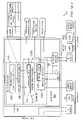
FIG. 2 illustrates one embodiment of a Multiservice Provisioning Platform (MSPP) of FIG. 1;
FIG. 3 illustrates another embodiment of an MSPP of FIG. 1
FIG. 4 illustrates one embodiment of conversion of a VLAN packet to a MPLS packet to a VLAN packet in the network of FIG. 1;
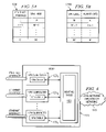
FIG. 5A illustrate one embodiment of conversion tables of the subrouter of FIG. 2;
FIG. 5B illustrate one embodiment of conversion tables of the subrouter of FIG. 3;
FIG. 6 illustrates one embodiment of the Ethernet line card of FIG. 2;
FIG. 7A illustrates one embodiment of the MSPP of FIG. 2;
FIG. 7B illustrates one embodiment of the MSPP of FIG. 3;
FIGS. 8A-B illustrate one embodiment of the VPN tables of FIG. 9;
FIG. 9 illustrates one embodiment of a first part of a method for VLAN-mapped MPLS/SONET transmit processing;
FIG. 10 illustrates one embodiment of a second part of the method for VLAN-mapped MPLS/SONET transmit processing;
FIGS. 11A-B illustrate one embodiment of correspondence between user priority and a VLAN and IP precedence and MPLS/SONET;
FIG. 12 illustrates exemplary transmission of packets between MSPPs of MPLS/SONET network of FIG. 1; and
FIG. 13 illustrates exemplary processing of packets by the MSPP illustrated in FIG. 3.
DETAILED DESCRIPTION OF THE DRAWINGS
FIG. 1 illustrates one embodiment of a shared label switching over SONET system 100. At a high level, system 100 includes a shared label switching over SONET network 110 coupled to virtual local area networks (VLANs) 101-104 and a disparate shared label switching network 105 to form a plurality of virtual private networks (VPNs) and provide Ethernet Multiplexing Functions (EMF). In this embodiment, the VPNs are Layer-2 (L2) VPNs. Layer-3 or other layer VPN could be used. In this embodiment, each shared label switching over SONET network is a multiprotocol label switching over SONET (MPLS/SONET) network. MPLS provides a path (a virtual communication path) into an IP network. It will be understood that the shared network may comprise other label switching networks, Internet Protocol (IP) networks or other suitable networks with tunneling or other functionality to support geographically distributed VPNs and/or EMF. For example, non-IP such as IPX, FNA, AppleTalk and the like may be implemented.
Referring to FIG. 1, a mixed network comprises a shared MPLS network 110, VLANs 101-104 and a IP/IMPLS network 105. Schemes for implementing a VLAN include (1) port-based VLAN, (2) MAC-address based database VLAN and (3) policy-based VLAN. An MPLS/SONET network may comprise Label Switching Routing (LSRs). As described in more detail below, the VLANs 101-104 are managed by prescribed VLAN IDs (VIDs). Each VID may be associated with a VPN, such as a L3 or L2 VPN, or, alternatively, a network service such as, for example, Internet, Voice-over-IP (VoIP), or other suitable services. The shared MPLS/SONET network 110 is managed by labels and may be constructed on the Internet or other Wide Area Network (WAN). The edges of the MPLS network 110 are provided with Multiservice Provisioning Platforms (MSPPs) 111-114. MSPPs 111-114 may be any suitable device within or connected to the shared core network and operable to interface between a VLAN 101-104 (or other suitable LAN) and the shared core network 110 and to switch, route, direct, bridge, convert or otherwise process and/or send traffic. Additionally, MSPPs 111-114 may be operable to interface between a IP/MPLS network and the Shared core network 110. For example, MSPPs 111-114 may comprise Label Edge Routers (LERs). As used herein, send means to forward, allow or initiate forwarding or sending, transmitting or otherwise directing.
Each MSPP 111-114 converts ingress packets, such as VLAN packets from the VLANs 101-104 or IP packets from network 105, to MPLS packets and transmits the MPLS packets over one or more SONET paths in the MPLS/SONET network 110. Each MSPP 111-114 is further operable to convert MPLS packets to egress VLAN packets or IP packets and output the packets to prescribed VLANs or to disparate MPLS network respectively.
In a particular embodiment, as described in more detail below, each MSPP 111-114 finds a VPN label, which is a VPN identifier associated within an ingress Ethernet interface of a VLAN packet, finds a forwarding label, for forwarding the packet along a prescribed route on the basis of the destination of the VLAN packet, impose these labels to generate an MPLS packet, and sends the MPLS packet to the MPLS/SONET network 110 by mapping the MPLS packet into one or more SONET paths. As used herein, find means to look-up, determine, retrieve or otherwise become aware of. The MPLS/SONET network 110 routes the MPLS packet to the target MSPP 111-114 over a preset route while the forwarding label of the packet, if included, is replaced. In the illustrated embodiment, the preset route is based on the ingress Ethernet interface, such as the ingress port. Upon receiving the MPLS packet from the MPLS/SONET network 110, a MSPP 111-114 receiving the MPLS packet removes any included forwarding label, converts the VPN label to a VID, adds the VID to the packet in place of the label to generate a VLAN packet and sends the VLAN packet to the VLAN 101-104 indicated by the VID. In the case where MSPP 100 sends VLAN packets that originated in VLANs 101, 103, or 104 to VLAN 102, system 100 provides EMF. Or, alternatively, MSPP 111-114 may additionally convert the VLAN packet to an MPLS packet for transmission through a disparate MPLS network such as, for example, IP/MPLS network 105. In this embodiment, system 100 provides service multiplexing. A packet can be transmitted from a VLAN 101-104 transmitting a packet belonging to a certain VPN to a disparate VLAN 101-104 (or IP/MPLS network 105) receiving the packet and belonging to the same VPN. As mentioned above, after the VID is added to the packet in place of the VPN label, MSPP 111-114 may generate a MPLS packet for transmission over a disparate MPLS/SONET network, such as network 105. In this case, if the VID is not associated with VLAN 102, then MSPP 112 generates a MPLS packet and sends it to network 105 via edge router 115.
The VLANs 101-104 are each connected to MPLS/SONET network 110 by Ethernet interfaces. As used herein, each means every one of at least a subset of the identified items. SONET means Synchronous Optical Networks including Synchronous Signal Digital Hierarchy (SDH) networks. To support EMF/SONET, the network elements of each VLAN 101-104 or network 105 may include MSPPs 111-114 which map Ethernet services over one or more SONET paths.
A SONET path or a virtual concatenation of SONET paths provides a point-to-point tunnel. Traditional SONET paths include STS-1 (51.84 Mbps), STS-Nc (e.g., 622.08 Mbps for STS-12c) and VT1.5 (1.728 Mbps) paths. Virtual concatenation combines a number of SONET paths (e.g., 5 STS-3c, virtually concatenated into STS-3c-5v) to present a single payload to the EoS adaptation layer. Virtual concatenation provides additional bandwidth granularity for tunnels (i.e., at integer multiples of traditional SONET rates) in a manner that is transparent to the SONET network as virtual concatenation is visible only to SONET path terminating elements and the SONET network operates at the SONET section and line layers.
In the mixed network, edge network elements of the VLANs 101-104 and of the MPLS/SONET network 110 includes SONET interfaces that support physical layer channelization in which Synchronous Transport Signal (STS) or Virtual Tributary (VT) paths are multiplexed onto a single physical interface.
FIG. 2 illustrates one embodiment of MSPP 111 of FIG. 1. The other MSPPs may be identically or similarly constructed. MSPP 111 may be otherwise suitably constructed with disparate elements and/or with its functionality otherwise distributed or combined. The functionality of MSPP 111 and other components of the network may be performed by logic and encoded in media. The logic may be hardware or software based.
Referring to FIG. 2, MSPP 111 has one or more Ethernet line cards 121 equipped with an Ethernet interface function for receiving a VLAN packet from a certain VLAN. Each Ethernet line card 121 may be associated with a separate VPN identification unit 122. Alternatively, a single VPN identification unit 122 may be associated with the plurality or all of the Ethernet line cards 121 of the MSPP 111. The VPN identification unit 122 identifies, in one embodiment, a VPN by referring to the ingress Ethernet interface and inputs the packet to a tag/label converter (subrouter) 123 i(i=1, 2, . . . ) that corresponds to the VPN. The subrouter 123 i corresponding to the identified VPN has a conversion table 124 which, in one embodiment, sorts the correspondence between (1) Ethernet interfaces and (2) VPN identifiers (VPN labels) that specify VPNs to which the VLAN packet belongs. Details of the conversion table 124 are illustrated in FIG. 5A.
MSPP 111 may further include a route decision unit 131 for deciding beforehand a route to a MSPP 111-114 receiving an MPLS packet using a routing protocol 132 and storing in a MPLS/SONET network routing table (forwarding-memory) 133 a forwarding label and an egress interface. The egress interface may include a SONET path and an outgoing interface. The forwarding label may comprise a null forwarding label or an IP forwarding label (a push label). The null forwarding label has 0 bytes and is included when the egress interface provides sufficient context for a corresponding VPN. In one embodiment, MSPP 111 comprises a half bridge. As used herein, a half bridge is any software, hardware, or firmware operable to only replicate data toward MPLS/SONET network 110, only learns layer 2 address information from the MPLS/SONET network 110, and performs split horizon forwarding (i.e., does not forward data received from the MPLS/SONET network 110 back to the MPLS/SONET network 110). In this embodiment, MPLS/SONET network 110 emulates Ethernet LAN functions and thus does not participate in the Ethernet switch control plane, thereby passing Ethernet switch control traffic transparently. In so doing, MPLS/SONET network 110 eliminates redundant bridging functions.
Each MPLS/SONET line card 128 is coupled to route decision unit 131 and MPLS/SONET network 110. MPLS/SONET line card 128 is operable to receive an MPLS packet from route decision unit 131 and communicate an MPLS packet to MPLS/SONET network 110 by mapping the MPLS packet into one or more SONET paths. For conversion from MPLS/SONET packet to VLAN packet, each MPLS/SONET line card 128 may be associated with a VLAN identification unit 129. The VLAN identification unit 129 identifies, in one embodiment, a VPN by referring to the VPN label of the received MPLS packet and inputs the packet to subrouter 123 i corresponding to the VPN. Line card 128 may be any software, hardware, or firmware operable to map an MPLS packet into a one or more SONET paths, using methods that include, but not limited to, SONET virtual concatenation.
In one aspect of operation, Ethernet line card 121 receives a VLAN packet from VLAN 101 over an ingress Ethernet interface which passes the received VLAN to VPN identification unit 122. VPN identification unit identifies the VPN by reference to the Ethernet interface and inputs the VLAN packet to the subrouter 123 i corresponding to the identified VPN. Subrouter 123 i imposes a VPN label associated with the ingress Ethernet interface. Based upon the ingress Ethernet interface route decision unit 131 retrieves a forwarding label and egress interface associated with the ingress interface from forwarding memory 133. If the egress interface does not provide sufficient content for routing the packet through MPLS/SONET network 110, route decision unit 131 imposes a push label on layer 1. In either case, route decision unit 131 forwards the MPLS packet egress MPLS/SONET based line card 128. MPLS/SONET line card 128 maps a received MPLS packet into a SONET path for transmission of the MPLS packet over MPLS/SONET network 110.
FIG. 3 illustrates one embodiment of MSPP 112 of FIG. 1. The other MSPPs may be identically or similarly constructed. MSPP 112 may be otherwise suitably constructed with disparate elements and/or with its functionality otherwise distributed or combined. The functionality of MSPP 112 and other components of the network may be performed by logic and encoded in media. The logic may be hardware or software based.
Referring to FIG. 3, MSPP 112 includes a first half bridge 342 and a second half bridge 344. In general, the first half bridge 342 receives MPLS packets from MPLS/SONET network 110 via MPLS/SONET line card 128A and generates a VLAN packet based, in part, on the ingress Ethernet interface which may be forwarded to VLAN 102 or second half bridge 344. The second half bridge 344 receives the generated VLAN packet and generates an MPLS packet for transmission over MPLS/SONET network 105 via MPLS/SONET line card 128B. The first half bridge 342 converts based on the ingress Ethernet interface between MPLS packets and VLAN packets and thus includes analogous features and functions of MSPP 111 illustrated in FIG. 2. In this case, any included forwarding label is removed. Accordingly, the description of MSPP 111 above analogously applies to the first half bridge 342 and Ethernet line card 121.
The first half bridge 342 has one or more MPLS/SONET line card 128 is equipped with a SONET interface function for receiving a MPLS packet from MPLS/SONET network 110. Each MPLS/SONET line card 128 may be associated with a VLAN identification unit 129. Alternatively, a single VLAN identification unit 129 may be associated with a plurality or all of the MPLS/SONET line cards 128, coupled to route decision unit 131 and MPLS/SONET network 110. The VLAN identification unit 129 identifies, in one embodiment, a VPN by referring to the VPN label of the received MPLS packet and inputs the packet to subrouter 123Ai corresponding to the VPN. The subrouter 123Ai corresponding to the identified VPN has a conversion table 124 which, in one embodiment, sorts the correspondence between (1) VLAN IDs (VIDs) and (2) VPN identifiers (VPN labels) that specify VPNs to which the VLANs specified by the VIDs belong and switches between the VPN label and VID. In this embodiment, both the VID and VPN labels are associated with the ingress Ethernet interface and these VIDs will be referred to as outer VIDs as compared with the VID included in the original VLAN packet. The VID included in the original VLAN packet will be referred to as the inner VID. Details of the conversion table 124 are illustrated in FIG. 5B.
The first half bridge includes may further include a route decision unit 131A that provides the forwarding label and egress interface for transmission through MPLS/SONET network 110 and thus includes the same features and functions of MSPP 111 as described above. In the case of a MPLS packet received from MPLS/SONET network 110, route decision unit 131A determines an ingress interface for the VLAN packet constructed from the MPLS packet. In one embodiment, if the combined inner and outer VIDs of a VLAN packet are identified, then the VLAN packet is forward to the second half bridge 344 via an internal interface 134, for conversion to an MPLS packet for transmission over MPLS network 105. Otherwise, route decision unit 131A forwards the VLAN packet to Ethernet line card 121.
The second half bridge includes route decision unit 131B, subrouter 123Bi, and VPN identification unit 129. The one or more MPLS/SONET line cards 128B is equipped with a SONET interface function for transmitting receiving MPLS packets to and from MPLS/SONET network 105. Each MPLS/SONET line cards 128B may be associated with a separate VPN identification unit 129. Alternatively, a single VPN identification unit 129 may be associated with the plurality or all of MPLS/SONET line cards 128B of the MSPP 112. The VPN identification unit 129 identifies, in one embodiment, a VPN that extends between networks 105 and 110 by referring to the VPN label of the received MPLS packet and inputs the packet to a tag/label converter (subrouter) 123Bi (i=1, 2, . . . ) that corresponds to the VPN. The subrouter 123Bi corresponding to the identified VPN has a conversion table 124B which, in one embodiment, sorts the correspondence between (1) outer VIDs and (2) VPN labels that specify VPNs associated with an Ethernet interface. Details of the conversion table 124B are illustrated in FIG. 5B.
Route decision unit 131B decides beforehand a route to a MSPP of network 105 receiving an MPLS packet using a routing protocol 132B based on an associated inner and outer VIDs and storing in a forwarding-memory 133B a forwarding label and an egress interface. The egress interface may include a SONET path and an outgoing interface. The forwarding label may comprise a null forwarding label or a push label. The null forwarding label has 0 bytes and is included when the egress interface provides sufficient context for a corresponding VPN. After imposing any forwarding label, the MPLS packet are forwarded to the appropriate egress interface, i.e., MPLS/SONET line card 128B. MPLS/SONET line cared 128B communicates the packet to network 105 by mapping the MPLS packet on to a SONET path.
MPLS/SONET line card 128 is operable to receive an MPLS packet from route decision unit 131 and communicate an MPLS packet to an MPLS/SONET network 105 by mapping the MPLS packet into a SONET path. Line card 128 may be any software, hardware, or firmware operable to map an MPLS packet into one or more SONET paths, a forwarding label (a push label), which specifies the decided route, in an MPLS network routing table (forwarding-memory) 133 in correspondence with the IP address of the receiving MSPP.
In one aspect of operation, MSPP 112 receives a packet from MPLS/SONET network 110. The received MPLS packet is received by MPLS/SONET line card 128 and VPN identification unit 129A. VPN identification unit 129A identifies the associated VPN and forwards the MPLS packet to the appropriate subrouter 123Ai. Subrouter 123Ai removes the VPN label and adds an outer tag including an outer VID associated with the ingress Ethernet Interface. As a result, the packet now includes an inner and an outer VID. After adding the outer VID, subrouter 123Ai forwards the packet to route decision unit 131A that removes any forwarding label and determines whether the combined inner and outer VID are recognized for determining an egress interface. If the combination is not recognized, the VLAN packet is forward to Ethernet line card 121. If recognized, the VLAN packet is forwarded to the second half bridge 344 for conversion to an MPLS packet. Based on the outer VID, route decision unit 131B forwards the VLAN packet to a subrouter 123Bi associated with the outer VID. Subrouter 123Bi converts the VID to VPN label where both are associated with the ingress Ethernet interface. Once converted, the packet is then forwarded to route decision unit 131B for determining a forwarding label and egress interface. Route decision unit 131B imposes the forwarding label and forwards the MPLS packet to MPLS/SONET line card 128B for mapping onto one or more SONET paths.
FIG. 4 illustrates one embodiment of conversion of a VLAN packet to an MPLS packet and to VLAN packet. As used in herein, conversion means to swap, translate, transition or otherwise modify addressing information in a packet. In this embodiment, a VPN label and a forwarding label are added to a VLAN packet to generate the MPLS packet. The VLAN packet may be otherwise suitably converted to an MPLS or other label switching packet. Once received by a destination MSPP, the VPN label is swapped for an outer tag and the forwarding label is removed.
Referring to FIG. 4, when a VLAN packet 150 enter, the subrouter 123 i of, for example, MSPP 111 refers to conversion table 124 to find the VPN identifier (VPN label) 156 corresponding to the ingress Ethernet interface. Route decision unit 131 finds the receiving MSPP 111-114 based upon the ingress Ethernet interface and finds, if appropriate, forwarding label 158, which has been stored in correspondence with the ingress Ethernet interface, from the MPLS network routing table 133.
Subrouter 123 i inserts VPN label 156 and route decision unit 131 inserts forwarding label 158 into VLAN packet 150 to generate MPLS packet 154. MPLS packet 154 is sent to MPLS network 110 via MPLS/SONET line card 128. MPLS/SONET line card 128 may be equipped with an MPLS over SONET interface function for receiving a MPLS packet from route decision unit 131 and mapping the received MPLS packet into one or more SONET paths. MPLS/SONET network 110 routes MPLS packet 154 to the target MSPP 114 over the preset route while replacing, where appropriate, forwarding label 158. MPLS/SONET line card 128 of the receiving MSPP 111-114 receives an MPLS packet 154 from MPLS/SONET network 110 the MPLS/SONET line card 128 converts the received MPLS packet to a VLAN packet 160. The VPN identification unit 129A identifies the VPN by referring to VPN label 156 of MPLS packet 154 and inputs the packet to the subrouter 123 i (i=1, 2, . . . ) that corresponds to the VPN.
Subrouter 123 i refers to conversion table 124 to find the outer VID that corresponds to VPN label 156. Subrouter 123 i then generates a VLAN packet 160 by adding an outer tag 162, which includes the VID found, in place of the VPN label 156. If route decision unit 131A does not identify the combined inner and outer VID, then route decision unit 131A forwards VLAN packet 160 to Ethernet line card 121 for transmission over VLAN 102. If the combination is identified, route decision unit 131A forwards VLAN packet 160 to the second half bridge 344. The second half bridge generates an MPLS packet for transmission over MPLS/SONET network 105, as discussed above. It should be noted that the contents of table 124 are not the same in each MSPP 111-114 and that the VID values of VLANs that belong to the same VPN are not necessarily the same. Further, though not shown clearly in FIG. 2, a subrouter may exist for every VPN, as illustrated in FIG. 6.
Thus, for example, when communication is initiated from VLAN 101 to VLAN 102 in FIG. 1, label 156 is imposed by MSPP 111 and label 156 and tag 162 are swapped by MSPP 112 in the manner shown in FIG. 4. As a result, VLAN packet 150 that enters from VLAN 101 side is changed to an MPLS packet 154 by MSPP 111, MPLS packet 154 is transmitted through MPLS/SONET network 110 and is converted to a VLAN packet 160 by MSPP 112, and this VLAN packet is then transmitted to a VLAN 102 belonging to a VPN identical with that on the transmit side.
FIG. 6 illustrates one embodiment of Ethernet line card 121 of FIG. 2. In this embodiment, an Ethernet interface is provided for each Ethernet channel. The Ethernet line card 121 may be otherwise suitably configured in its functionality otherwise distributed or otherwise distributed or combined. Referring to FIG. 6, Ethernet line card 121 includes a plurality of Ethernet interfaces, where each interface carries at least one Ethernet channel. In this embodiment, each Ethernet interface need not be coupled to a corresponding VPN identification unit 122.
In operation, an Ethernet channel is received by an ingress Ethernet interface. The ingress Ethernet interface forwards each channel directly to a corresponding subrouter 123 i for connection. For egress traffic from MSPP 111, subrouter 123 i determines an outgoing interface (port) and sub-interface (channels) based on the egress interface provided by the subrouter 123 i.
FIG. 7A-B illustrate one embodiment of MSPP 111 of FIG. 2 and MSPP 112 of FIG. 3, respectively. Components in FIG. 7A-B that are identical to those of FIGS. 2 and 3 are designated by like reference characters.
Ethernet line card 121, which has an Ethernet interface function, receives a VLAN packet from a prescribed VLAN 101-104. As previously described, the VLAN packet is received via Ethernet channels and forwarded to the corresponding VPN identification unit 122. The VPN identification unit 122 identifies the VPN either by referring to the VID or ingress Ethernet interface of the received VLAN packet and inputs the packet to the subrouter 123 i that corresponds to this VPN. As shown in (a) of FIGS. 10A and 10B, the L2 label table 124 of the subrouter 123 i stores, in one embodiment, the correspondence among (1) VPN labels (VPN identifiers), (2) L2 addresses (MAC addresses) of CPE routers under control, (3) output-side interfaces, (4) identifiers (VIDs) of VLANs connected to MSPPs, and (5) VPNi (VPN Instance): a convenient name for VPN identifier. The outgoing interface field may include a physical interface and one or more SONET paths.
FIG. 8A illustrates the initial state and FIG. 8B the state that results after various data have been set. A L 2 VPN routing table 125, in one embodiment, stores (1) a L2 address (MAC address) of the CPE router within a VLAN, (2) a loopback address (IP address) of the MSPP to which the CPE router is connected, and (3) an identifier (VID) of the VLAN to which the CPE router belongs, as shown in (B) of FIGS. 8A and 8B.
The MPLS network routing table (forwarding-label memory) 133 stores forwarding labels which specify the route to the received MSPP 111-114 and egress interfaces. Using a routing protocol, the route decision unit for deciding the route within the MPLS/SONET network 200 searches for routes from the transmitting MSPP 111-114 to the receiving MSPP 111-114 and assigns a forwarding label and an egress interface to each route in accordance with the LDP (label distribution protocol) in such a manner that the VLANs belonging to the same VPN can communicate with one another. Accordingly, route decision unit 131 decides the route to the receiving MSPP 111-114 using routing protocol 132 and stores forwarding label 158 (push label), where appropriate, in SONET path, and outgoing interface, in the forwarding label table 133 in a form mapped to the loopback address (IP address) of the receiving MSPP 111-114.
If VPN label 156 and push label 158 have been found, subrouter 123 i imposes VPN label 156 and forwarding label 158 to generate an MPLS packet 154, as shown in FIG. 4, and passes MPLS packet 154 to MPLS/SONET line card 128 to map MPLS packet 154 into one or more SONET paths. MPLS packet 154 arrives at the receiving MSPP 111-114 along the preset route through the MPLS/SONET network 110 while its forwarding label 158, if included, is replaced. MPLS/SONET line card 128 of the receiving MSPP 111-114, terminates the SONET path(s), receives the MPLS packet 154 from MPLS/SONET network 110, and passes a corresponding MPLS packet to VPN identification unit 129. VPN identification unit 129 identifies the VPN by referring to VPN label 156 of MPLS packet 154 and inputs packet 154 to the subrouter 123 i (i=1, 2, . . . ) corresponding to the VPN and the SONET path(s) over which MPLS packet 154 was received. Subrouter 123 i removes the forwarding label 158, if included, and refers to the VPN label table 124 to find the VID corresponding to VPN label 156. Subrouter 123 i then swaps tag 162, which contains the VID, for VPN label 156 to thereby generate a VLAN packet 160 and sends this VLAN packet 150 via line card 121 to the VLAN if the combined inner and outer VIDs are not identified. Alternatively, the VLAN packet may be forwarded to a second half bridge 344 for conversion to an MPLS packet destined for a disparate MPLS/SONET network if the combined inner and outer VIDs are identified. It should be noted that the VPN label tables 124 and MSPPs 111-114 are not identical in content and that the VID values of VLANs that belong to the same VPN are not necessarily the same. Further, though not shown clearly in FIG. 7A-B, subrouter 123 i (i=1, 2, . . . ) and forwarding label table 123 may exist per every VPN. In order to arrange it so that VLANs belonging to a VPN can communicate with each other, a route is established beforehand between MSPPs 111-114 to which these VLANs are connected to and forwarding labels and egress interfaces are stored in forwarding label table 133 (FIG. 7A-B) of the router along the route, and the VPN label table 124 and L2 VPN routing table 125 are created.
FIGS. 9-10 illustrate one embodiment of the method for VLAN-mapped MPLS/SONET transmit processing. In this embodiment, VLAN packets 150 are received via Ethernet channels and transmitted as MPLS packets over one or more SONET paths in MPLS/SONET network 110 of FIG. 1.
Referring to FIGS. 9-10, when a packet arrives as an input via an ingress Ethernet interface, MSPP 111-114 determines the ingress Ethernet interface at step 302. Next, at step 306, subrouter 123 i refers to the VPN label table at step 304. The MSPP adds a VPN label value (VPN label) 156 associated with the ingress Ethernet interface at step 306.
If a forwarding label is required at step 308, then the execution proceeds to step 310. At step 310, MSPP 111-114 refers to forwarding label table 133 to find the forwarding label (push label) and imposes the push label on MPLS packet 154. If the forwarding label is not required, then execution proceeds to step 314. At step 314, the MPLS packet is passed to an MPLS/SONET line card 128 based on the ingress Ethernet interface. At step 316, the packet 154 is sent to MPLS/SONET line card 128 to map the MPLS packet 154 into a SONET path.
The above is the processing executed by MSPP 111-114 on the transmitting side. This is followed by execution of processing for routing MPLS packet 154 through MPLS/SONET network 110. MPLS packet 154 is forwarded to the target MSPP 111-114, along the set route through MPLS/SONET network 110 while forwarding label 158, if included, is replaced at step 318.
The receiving MSPP 111-114 removes any included forwarding label 158 at step 320. Next, MSPP 111-114 extracts the VPN label 156 at step 322, refers to table 124 indicating the correspondence between the outer VLAN ID (=VID) and VPN label at step 324 and checks to see whether the VID has been found at step 326. If the outer VID was not found, MSPP 111-114 discards packet 154 at step 328. If the VID has been found, however, MSPP 111-114 removes VPN label 156 and adds an outer tag 152 that contains the outer VID to create a VLAN packet 160 at step 330. Next, MSPP 111-114 refers to the combined inner and outer VIDs at step 332 to determine if the combined VIDs is identified. If the combination is not identified at decisional step 334, then, at step 336, MSPP 114 forwards the VLAN packet 160 to an Ethernet line card 121 for transmission through VLAN 102. If the combination is identified at decisional step 334, then MSPP 114 refers to the outer VID at step 338. Next, at step 340, MSPP 112 extracts the value of the outer VLAN ID (=VID) contained in tag 160. The MSPP removes tag 162 and imposes a VPN label at step 342. If a forwarding label is required at step 344, then the execution proceeds to step 346. MSPP 112 refers to forwarding label table 133 to find the forwarding label (push label) at step 346 and imposes the push label at step 348. If the forwarding label is not required, then execution proceeds to step 350. At step 350, the MPLS packet is passed to an MPLS/SONET line card 128B based on the VPN label and the MPLS packet 154 is mapped to one or more SONET paths for transmission over network 105.
FIGS. 11A-B illustrate one embodiment of correspondence between user priority and a VLAN and IP precedence and MPLS. Referring to FIG. 17A, tag 152 of a VLAN packet 150 includes three-bit user priority and it is arranged so that the priority value stipulated by each MAC is entered using these three bits. A priority value can take on eight values of 0-7. User priority is low if the value is small (e.g., zero) and high if the value is large.
The label of an MPLS packet 154, on the other hand, includes a three-bit experimental field EXP, as shown in FIG. 17B. IP precedence is expressed using these three bits. IP precedence also is a priority value that can take on eight levels of 0-7. Priority is low if the value is small (e.g., zero) and high if the value is large. Accordingly, when a conversion is made from a VLAN packet 150 to an MPLS packet 154 in an MSPP 211-213, the three-bit user priority is inserted into the EXP field. When a conversion is made from an MPLS packet 154 to a VLAN packet 150, the IP precedence of the three-bit EXP field is inserted into the user-priority field. Thus, in one embodiment, priority control in a VLAN can be continued as IP precedence control in an MPLS network. Further, it is possible to return from IP precedence control to the original priority control in a VLAN.
FIG. 12 illustrates exemplary transmission of packets between MSPPs of MPLS/SONET network 110 of FIG. 1. In particular, FIG. 12 illustrates example STS paths in which MPLS packets are transmitted from MSPP 111 and 114 to MSPP 112.
MSPP 111 receives ingress VLAN packets 150 over ports 1 to 4. When each packet 150 enters MSPP 111, the router generates an MPLS packet 154 by adding VPN label 156 associated with the ingress Ethernet interface and forwarding label 158 (push label), where appropriate, and maps the MPLS packet over a SONET path such as, for example, STS path number 1-3. MPLS packet 154 subsequently arrives at the receiving MSPP 112 along the preset path through MPLS/SONET network 110 while its forwarding label 158, if included, is replaced. The receiving MSPP 112 creates VLAN packet 160 by removing labels 156 and 158 and adding an outer tag 162 including an outer VID that is associated with the ingress interface. MSPP 112 sends the VLAN packet 160 to the appropriate interface based on the combined inner and outer VID, which may be an internal interface 134 or an Ethernet line card 121.
FIG. 13 illustrates exemplary processing of packets of MSPP 112 of FIG. 3. In particular, FIG. 13 illustrates example label switch paths (LSPs) in which MPLS packets are transmitted from MSPP 112 to MPLS network 105 of FIG. 1.
MSPP 112 receives MPLS packets 154 over STS paths number 1 and 3. When each packet 154 enters MSPP 112, the first half bridge 342 generates a VLAN packet 160 by removing VPN label 156 associated with the ingress Ethernet interface and forwarding label 158 (push label), where appropriate, and adding an outer tag 162 including an outer VID. In one embodiment, the first half bridge 342 looks up the conversion of the VPN label in the table illustrated in FIG. 5B. The first half bridge 342 refers to the inner and outer VID of each VLAN packet 160 to determine if the combination of VIDs are identified. If the combine VIDs are not identified, the first half bridge 342 forwards the VLAN packet 160 to VLAN 102 via Ethernet line card 121. If the first half bridge does identify the combined VIDs, the first half bridge forwards the VLAN packet 160 to the second half bridge 344 for conversion to an MPLS packet for transmission over network 105. The second half bridge removes the outer tag 162 and replaces it with a VPN label and forwarding label and maps the MPLS packet on to one or more SONET paths in network 105.
Although the present invention has been described in detail, various changes and modifications may be suggested to one skilled in the art. It is intended that the present invention encompass such changes and modifications as falling within the scope of the appended claims.

Claims (16)

1. A virtual private network (VPN), comprising:
a first core network and a second core network, each core network comprising a SONET over shared label switching network;
a plurality of Virtual Local Access Networks (VLANs), each coupled to a Multiservice Provisioning Platform (MSPP) of the first and second core networks, the VLANs each communicating traffic with a corresponding MSPP utilizing Ethernet over a plurality of Ethernet interfaces; and
the MSPP interfacing the VLANs with the first and second core networks based, in part, on the plurality of Ethernet interfaces, wherein the MSPP comprises a first half bridge operable to only replicate traffic entering the first core network, only learn layer 2 address information from the first core network, and perform split horizon forwarding, and wherein the MSPP comprises a second half bridge operable to only replicate traffic entering the second core network, only learn layer 2 address information from the second core network, and perform split horizon forwarding.
2. The VPN of claim 1, wherein the shared label switching comprises Multiprotocol Label Switching (MPLS).
3. The VPN of claim 2, the MSPP each operable to convert an ingress VLAN packet received from a first VLAN and associated with an ingress Ethernet interface to an MPLS packet and to send the MPLS packet to the SONET network based on the ingress Ethernet interface; and convert the MPLS packet over SONET packet received from the SONET network to either an egress MPLS packet associated with a disparate SONET network or an egress VLAN packet.
4. The VPN of claim 3, the MSPP each comprising a first table storing correspondence between VLAN identifiers (VIDs) contained in VLAN packets and VPN labels contained in MPLS packets.
5. The VPN of claim 4, wherein an MSPP transmitting traffic entering one of the core networks is operable to determine a VPN label, the VPN correspondence to a VLAN identifier (VID) of a VLAN packet, from the first table, generates an MPLS packet having the VPN label and transmits the MPLS packet over the core network.
6. The VPN of claim 5, wherein an MSPP receiving traffic exiting one of the core networks is operable to determine a VID, which corresponds to a VPN label contained in an MPLS packet received from the SONET network, from the first table, generates a VLAN packet having the VID and transmits the VLAN packet to a VLAN indicated by the VID.
7. The VPN network of claim 6, wherein each MSPP comprises:
a route decision unit for determining an outgoing interface which directs an MPLS packet to an egress MSPP associated with the Ethernet interface and is operable to receive egress traffic exiting one of the core networks; and
a second table for storing egress interfaces mapped to addresses of egress MSPPs.
8. The VPN of claim 7, wherein an MSPP transmitting ingress traffic entering one of the core networks is operable to determine an outgoing interface, which corresponds to the egress MSPP, from the second table, generates an MPLS packet that contains the VPN label and sends the MPLS packet to the SONET network.
9. The VPN network of claim 7, wherein the egress interface comprises a physical interface and a SONET path.
10. The VPN of claim 7, wherein the route decision unit further determines a forwarding label based on a corresponding Ethernet interface.
11. The VPN of claim 1, the core network operable to pass Ethernet control traffic transparently.
12. The VPN of claim 1, wherein the core network does not participate in a Ethernet switch control plane.
13. The VPN of claim 1, wherein the MSPP is further operable to interface the core networks with a disparate SONET network based, in part, on an associated VLAN identifier.
14. An Multiservice Provisioning Platform (MSPP) of a shared label switching over SONET network, comprising:
a first VPN subrouter coupled to an Ethernet interface and operable to convert a Virtual Local Access Network (VLAN) packet to a label switching packet based, in part, on the Ethernet interface and to send the label switching packet to a corresponding label switching over SONET line card;
a first label switching over SONET line card operable to receive a label switching packet from a first shared label switching over SONET network and map the label switching packet into one or more SONET paths for transmission over the first shared label switching over SONET network; and
a second label switching over SONET line card operable to receive a label switching over SONET packet from a second shared label switching over SONET network;
a shared label switching interface coupled to the second label switching over SONET line card and operable to receive a label switching over SONET packet from the second label switching over SONET line card;
a VPN unit coupled to the shared label switching interface and operable to identify a VPN for a label switching over SONET packet received by the interface and to send the label switching over SONET packet to a second VPN subrouter based on the VPN; and p1 the second VPN subrouter operable to convert the label switching packet to a VLAN based, in part, on a VLAN identifier and to send the VLAN packet to the first subrouter via the Ethernet interface for converting the VLAN packet to a label switching over SONET line packet based, in part, on the shared label switching interface.
15. The MSPP of claim 14, wherein the label switching over SONET network comprises a Multi Protocol Label Switching (MPLS) network.
16. The MSPP of claim 15, wherein each VPN subrouter is operable to convert a VLAN packet to an MPLS packet by replacing a tag of the VLAN packet with a VPN label and a forwarding label, or by retaining the tag of the VLAN packet and adding a VPN label and a forwarding label.
US10/856,586 2004-05-28 2004-05-28 Application of an Ethernet/MPLS half bridge to provide Ethernet multiplexing functions (EMF) in SONET network elements (NEs) Expired - Fee Related US7433359B2 (en)

Priority Applications (2)

Application Number Priority Date Filing Date Title
US10/856,586 US7433359B2 (en) 2004-05-28 2004-05-28 Application of an Ethernet/MPLS half bridge to provide Ethernet multiplexing functions (EMF) in SONET network elements (NEs)
JP2005155304A JP2005341591A (en) 2004-05-28 2005-05-27 Virtual private network, and multi-service provisioning platform and method

Applications Claiming Priority (1)

Application Number Priority Date Filing Date Title
US10/856,586 US7433359B2 (en) 2004-05-28 2004-05-28 Application of an Ethernet/MPLS half bridge to provide Ethernet multiplexing functions (EMF) in SONET network elements (NEs)

Publications (2)

Publication Number Publication Date
US20050265329A1 US20050265329A1 (en) 2005-12-01
US7433359B2 true US7433359B2 (en) 2008-10-07

Family

ID=35425157

Family Applications (1)

Application Number Title Priority Date Filing Date
US10/856,586 Expired - Fee Related US7433359B2 (en) 2004-05-28 2004-05-28 Application of an Ethernet/MPLS half bridge to provide Ethernet multiplexing functions (EMF) in SONET network elements (NEs)

Country Status (2)

Country Link
US (1) US7433359B2 (en)
JP (1) JP2005341591A (en)

Cited By (3)

* Cited by examiner, † Cited by third party
Publication number Priority date Publication date Assignee Title
US20060165087A1 (en) * 2004-12-06 2006-07-27 Nexagent Ltd. Interconnect system for supply chain management of virtual private network services
US20070253432A1 (en) * 2006-05-01 2007-11-01 Cisco Technology, Inc. Network device providing access to both layer 2 and layer 3 services on a single physical interface
US10855660B1 (en) * 2020-04-30 2020-12-01 Snowflake Inc. Private virtual network replication of cloud databases

Families Citing this family (23)

* Cited by examiner, † Cited by third party
Publication number Priority date Publication date Assignee Title
SE0200640D0 (en) * 2002-02-28 2002-02-28 Ericsson Telefon Ab L M Arrangement and method for routing in virtual private network
US20050220096A1 (en) 2004-04-06 2005-10-06 Robert Friskney Traffic engineering in frame-based carrier networks
US7430210B2 (en) * 2004-05-26 2008-09-30 Fujitsu Limited Application of an Ethernet/MPLS “half bridge” to provide emulated Ethernet LAN functions in SONET networks
US7433359B2 (en) 2004-05-28 2008-10-07 Fujitsu Limited Application of an Ethernet/MPLS half bridge to provide Ethernet multiplexing functions (EMF) in SONET network elements (NEs)
US8422500B2 (en) 2004-07-02 2013-04-16 Rockstar Consortium Us Lp VLAN support of differentiated services
US20060187924A1 (en) * 2005-02-18 2006-08-24 Broadcom Corporation Ingress handling of data in a network device
JP4173866B2 (en) * 2005-02-21 2008-10-29 富士通株式会社 Communication device
US9088669B2 (en) 2005-04-28 2015-07-21 Cisco Technology, Inc. Scalable system and method for DSL subscriber traffic over an Ethernet network
US8194656B2 (en) 2005-04-28 2012-06-05 Cisco Technology, Inc. Metro ethernet network with scaled broadcast and service instance domains
US8213435B2 (en) 2005-04-28 2012-07-03 Cisco Technology, Inc. Comprehensive model for VPLS
US8094663B2 (en) 2005-05-31 2012-01-10 Cisco Technology, Inc. System and method for authentication of SP ethernet aggregation networks
CN100377548C (en) * 2005-07-15 2008-03-26 华为技术有限公司 Method and device for realizing virtual exchange
US8554232B2 (en) * 2005-08-17 2013-10-08 Apple Inc. Method and system for a wireless multi-hop relay network
US20070140271A1 (en) * 2005-12-21 2007-06-21 Amante Shane M Method and system for terminating SONET/SDH circuits in an IP network
US7633956B1 (en) * 2006-01-19 2009-12-15 Cisco Technology, Inc. System and method for providing support for multipoint L2VPN services in devices without local bridging
US7986915B1 (en) * 2006-02-24 2011-07-26 Nortel Networks Limited Method and system for a wireless multi-hop relay network
US8054840B2 (en) * 2007-06-12 2011-11-08 International Business Machines Corporation Data center virtual local area network system and method
EP2190145A4 (en) * 2007-08-14 2012-06-13 Fujitsu Ltd Transmitting apparatus and transmitting method
EP2071861B1 (en) * 2007-12-12 2014-10-22 ADVA Optical Networking SE A method and a network for bidirectional transport of data
CN101277245B (en) * 2008-05-06 2012-05-23 华为技术有限公司 Method, system and apparatus for implementing L2VPN field across
US8411681B2 (en) * 2008-12-10 2013-04-02 Electronics And Telecommunications Research Institute Multicasting method in network including T-MPLS network and WDM network and apparatus therefor
US8427937B1 (en) * 2009-03-06 2013-04-23 Dragonwave, Inc. Bridging for SONET/SDH automatic protection switching
WO2018020447A1 (en) * 2016-07-27 2018-02-01 Megaport (Services) Pty Ltd Extending an mpls network using commodity network devices

Citations (22)

* Cited by examiner, † Cited by third party
Publication number Priority date Publication date Assignee Title
US6339595B1 (en) 1997-12-23 2002-01-15 Cisco Technology, Inc. Peer-model support for virtual private networks with potentially overlapping addresses
US20020110087A1 (en) * 2001-02-14 2002-08-15 David Zelig Efficient setup of label-switched connections
US20020176450A1 (en) 2001-01-31 2002-11-28 Sycamore Networks, Inc. System and methods for selectively transmitting ethernet traffic over SONET/SDH optical network
US20030110268A1 (en) 2001-12-07 2003-06-12 Francois Kermarec Methods of establishing virtual circuits and of providing a virtual private network service through a shared network, and provider edge device for such network
US20030174706A1 (en) 2002-03-15 2003-09-18 Broadcom Corporation Fastpath implementation for transparent local area network (LAN) services over multiprotocol label switching (MPLS)
US20030185223A1 (en) 2002-03-28 2003-10-02 Michael Tate Signaling methods for a telecommunication system and devices for implementing such methods
US6633571B1 (en) 1999-05-27 2003-10-14 Hitachi, Ltd. VPN composing method, interwork router, packet communication method, data communication apparatus, and packet relaying apparatus
US20040037279A1 (en) 2002-08-23 2004-02-26 David Zelig Virtual private LAN service using a multicast protocol
US20040076166A1 (en) 2002-10-21 2004-04-22 Patenaude Jean-Marc Guy Multi-service packet network interface
US20040081172A1 (en) 2002-09-13 2004-04-29 Hamid Ould-Brahim Generalized Layer-2 VPNs
US6757298B1 (en) 2000-10-10 2004-06-29 Cisco Technology, Inc. VLAN trunking over ATM PVCs (VTAP)
US20040146058A1 (en) 2002-12-12 2004-07-29 Sachiko Nemoto Frame transmission method
US6771662B1 (en) 2000-05-30 2004-08-03 Hitachi, Ltd. Label switching type of packet forwarding apparatus
US20040170713A1 (en) 1992-05-19 2004-09-02 Novogen Research Pty Ltd. Methods of cholesterol reduction using isoflavones
US6788681B1 (en) 1999-03-16 2004-09-07 Nortel Networks Limited Virtual private networks and methods for their operation
US20040174887A1 (en) 2003-02-21 2004-09-09 Alcatel Hybrid virtual private LAN extensions
US20050053079A1 (en) 2003-09-06 2005-03-10 Havala Paul F. Virtual private network (VPN) with channelized ethernet over sonet (EoS) interface and method
US20050265355A1 (en) 2004-05-26 2005-12-01 Fujitsu Limited Application of an ethernet/MPLS "half bridge" to provide emulated ethernet LAN functions in SONET networks
US20050265329A1 (en) 2004-05-28 2005-12-01 Fujitsu Limited Application of an Ethernet/MPLS half bridge to provide Ethernet multiplexing functions (EMF) in SONET network elements (NEs)
US6985488B2 (en) 2003-01-15 2006-01-10 Ciena Corporation Method and apparatus for transporting packet data over an optical network
US7079544B2 (en) 2000-06-02 2006-07-18 Hitachi, Ltd. Apparatus and method for interworking between MPLS network and non-MPLS network
US7242665B2 (en) 2001-01-25 2007-07-10 Ericsson Ab Network device virtual interface

Family Cites Families (3)

* Cited by examiner, † Cited by third party
Publication number Priority date Publication date Assignee Title
US6331978B1 (en) * 1999-03-09 2001-12-18 Nokia Telecommunications, Oy Generic label encapsulation protocol for carrying label switched packets over serial links
JP4183379B2 (en) * 2000-11-27 2008-11-19 富士通株式会社 Network and edge router
WO2004043013A1 (en) * 2002-11-07 2004-05-21 Tpack A/S Virtual ethernet mac switching

Patent Citations (22)

* Cited by examiner, † Cited by third party
Publication number Priority date Publication date Assignee Title
US20040170713A1 (en) 1992-05-19 2004-09-02 Novogen Research Pty Ltd. Methods of cholesterol reduction using isoflavones
US6339595B1 (en) 1997-12-23 2002-01-15 Cisco Technology, Inc. Peer-model support for virtual private networks with potentially overlapping addresses
US6788681B1 (en) 1999-03-16 2004-09-07 Nortel Networks Limited Virtual private networks and methods for their operation
US6633571B1 (en) 1999-05-27 2003-10-14 Hitachi, Ltd. VPN composing method, interwork router, packet communication method, data communication apparatus, and packet relaying apparatus
US6771662B1 (en) 2000-05-30 2004-08-03 Hitachi, Ltd. Label switching type of packet forwarding apparatus
US7079544B2 (en) 2000-06-02 2006-07-18 Hitachi, Ltd. Apparatus and method for interworking between MPLS network and non-MPLS network
US6757298B1 (en) 2000-10-10 2004-06-29 Cisco Technology, Inc. VLAN trunking over ATM PVCs (VTAP)
US7242665B2 (en) 2001-01-25 2007-07-10 Ericsson Ab Network device virtual interface
US20020176450A1 (en) 2001-01-31 2002-11-28 Sycamore Networks, Inc. System and methods for selectively transmitting ethernet traffic over SONET/SDH optical network
US20020110087A1 (en) * 2001-02-14 2002-08-15 David Zelig Efficient setup of label-switched connections
US20030110268A1 (en) 2001-12-07 2003-06-12 Francois Kermarec Methods of establishing virtual circuits and of providing a virtual private network service through a shared network, and provider edge device for such network
US20030174706A1 (en) 2002-03-15 2003-09-18 Broadcom Corporation Fastpath implementation for transparent local area network (LAN) services over multiprotocol label switching (MPLS)
US20030185223A1 (en) 2002-03-28 2003-10-02 Michael Tate Signaling methods for a telecommunication system and devices for implementing such methods
US20040037279A1 (en) 2002-08-23 2004-02-26 David Zelig Virtual private LAN service using a multicast protocol
US20040081172A1 (en) 2002-09-13 2004-04-29 Hamid Ould-Brahim Generalized Layer-2 VPNs
US20040076166A1 (en) 2002-10-21 2004-04-22 Patenaude Jean-Marc Guy Multi-service packet network interface
US20040146058A1 (en) 2002-12-12 2004-07-29 Sachiko Nemoto Frame transmission method
US6985488B2 (en) 2003-01-15 2006-01-10 Ciena Corporation Method and apparatus for transporting packet data over an optical network
US20040174887A1 (en) 2003-02-21 2004-09-09 Alcatel Hybrid virtual private LAN extensions
US20050053079A1 (en) 2003-09-06 2005-03-10 Havala Paul F. Virtual private network (VPN) with channelized ethernet over sonet (EoS) interface and method
US20050265355A1 (en) 2004-05-26 2005-12-01 Fujitsu Limited Application of an ethernet/MPLS "half bridge" to provide emulated ethernet LAN functions in SONET networks
US20050265329A1 (en) 2004-05-28 2005-12-01 Fujitsu Limited Application of an Ethernet/MPLS half bridge to provide Ethernet multiplexing functions (EMF) in SONET network elements (NEs)

Non-Patent Citations (7)

* Cited by examiner, † Cited by third party
Title
European Search Report in European Patent Application No. EP 04 02 0905, Jan. 4, 2005, 2 pages.
Hama et al., U.S. Appl. No. 09/805,868, "Network and Edge Router," Filed Mar. 14, 2001, 51 pages, 25 drawings.
Jamieson et al., "MPLS VPN Architecture," Nortel Telecom Ltd., Aug. 7, 1998, 16 pages.
Lee et al., "End to End QoS Architecture for VPNs: MPLS VPN Development in a Backbone Network,", Electronics and Telecommunications Research Institute, IEEE 2000, pp. 479-483.
Paul F. Havala et al., U.S. Appl. No. 10/856,408, entitled "Application of an Ethernet/MPLS Half Bridge" to Provide Emulated Ethernet LAN Functions in Sonet Networks, May 26, 2004.
Rosen et al., "BGP/MPLS VPN's," Cisco Systems, Inc., Mar. 1999, 25 pages.
Vivace Networks, "Delivering Ethernet Traffic in MAN/WAN, Practical Ways to Offer Managed Ethernet Services," 2001, pp. 1-19.

Cited By (12)

* Cited by examiner, † Cited by third party
Publication number Priority date Publication date Assignee Title
US20060165087A1 (en) * 2004-12-06 2006-07-27 Nexagent Ltd. Interconnect system for supply chain management of virtual private network services
US7715429B2 (en) * 2004-12-06 2010-05-11 Hewlett-Packard Development Company, L.P. Interconnect system for supply chain management of virtual private network services
US20070253432A1 (en) * 2006-05-01 2007-11-01 Cisco Technology, Inc. Network device providing access to both layer 2 and layer 3 services on a single physical interface
US7881314B2 (en) * 2006-05-01 2011-02-01 Cisco Technology, Inc. Network device providing access to both layer 2 and layer 3 services on a single physical interface
US10855660B1 (en) * 2020-04-30 2020-12-01 Snowflake Inc. Private virtual network replication of cloud databases
US10999252B1 (en) * 2020-04-30 2021-05-04 Snowflake Inc. Private virtual network replication of cloud databases
US11063911B1 (en) 2020-04-30 2021-07-13 Snowflake Inc. Private virtual network replication of cloud databases
US11134061B1 (en) 2020-04-30 2021-09-28 Snowflake Inc. Private virtual network replication of cloud databases
US11223603B2 (en) 2020-04-30 2022-01-11 Snowflake Inc. Private virtual network replication of cloud databases
US11374908B2 (en) 2020-04-30 2022-06-28 Snowflake Inc. Private virtual network replication of cloud databases
US11539672B2 (en) 2020-04-30 2022-12-27 Snowflake Inc. Private virtual network replication of cloud databases
US11943203B2 (en) 2020-04-30 2024-03-26 Snowflake Inc. Virtual network replication using staggered encryption

Also Published As

Publication number Publication date
US20050265329A1 (en) 2005-12-01
JP2005341591A (en) 2005-12-08

Similar Documents

Publication Publication Date Title
US7430210B2 (en) Application of an Ethernet/MPLS “half bridge” to provide emulated Ethernet LAN functions in SONET networks
US7433359B2 (en) Application of an Ethernet/MPLS half bridge to provide Ethernet multiplexing functions (EMF) in SONET network elements (NEs)
US7366181B2 (en) Virtual private network (VPN) with channelized ethernet over sonet (EoS) interface and method
CA2413570C (en) Address resolution method for a virtual private network, and customer edge device for implementing the method
US6789121B2 (en) Method of providing a virtual private network service through a shared network, and provider edge device for such network
JP5106100B2 (en) Differential transfer in addressed carrier networks
EP1943785B1 (en) Multilink trunking for encapsulated traffic
US7733812B2 (en) Method for enabling multipoint network services over a ring topology network
US20030174706A1 (en) Fastpath implementation for transparent local area network (LAN) services over multiprotocol label switching (MPLS)
US20050129059A1 (en) Method of implementing PSEUDO wire emulation edge-to-edge protocol
US20010049739A1 (en) Apparatus and method for interworking between MPLS network and non-MPLS network
US7499449B2 (en) Virtual Ethernet MAC switching
US20050271036A1 (en) Method for providing efficient multipoint network services
US20070140271A1 (en) Method and system for terminating SONET/SDH circuits in an IP network
EP1318631B1 (en) Address resolution method for a virtual private network, and customer edge device for implementing the method
US9258140B2 (en) Architecture for routing data of a customer network over provider's network in provider backbone bridges
EP1351450B1 (en) Fastpath implementation for transparent local area network (LAN) services over multiprotocol label switching (MPLS)
CN116886663A (en) E-TREE implementation mode, device and communication equipment based on RFC 8317
Berger Delivering Ethernet services in the Metro

Legal Events

Date Code Title Description
AS Assignment

Owner name: FUJITSU LIMITED, JAPAN

Free format text: ASSIGNMENT OF ASSIGNORS INTEREST;ASSIGNORS:HAVALA, PAUL F.;LISLE, SAMUEL V.;CAI, BIAODONG;AND OTHERS;REEL/FRAME:015410/0926

Effective date: 20040527

STCF Information on status: patent grant

Free format text: PATENTED CASE

FEPP Fee payment procedure

Free format text: PAYOR NUMBER ASSIGNED (ORIGINAL EVENT CODE: ASPN); ENTITY STATUS OF PATENT OWNER: LARGE ENTITY

CC Certificate of correction
FPAY Fee payment

Year of fee payment: 4

FPAY Fee payment

Year of fee payment: 8

FEPP Fee payment procedure

Free format text: MAINTENANCE FEE REMINDER MAILED (ORIGINAL EVENT CODE: REM.); ENTITY STATUS OF PATENT OWNER: LARGE ENTITY

LAPS Lapse for failure to pay maintenance fees

Free format text: PATENT EXPIRED FOR FAILURE TO PAY MAINTENANCE FEES (ORIGINAL EVENT CODE: EXP.); ENTITY STATUS OF PATENT OWNER: LARGE ENTITY

STCH Information on status: patent discontinuation

Free format text: PATENT EXPIRED DUE TO NONPAYMENT OF MAINTENANCE FEES UNDER 37 CFR 1.362

FP Lapsed due to failure to pay maintenance fee

Effective date: 20201007