US7706432B2 - Data transfer system, wireless communication device, wireless communication method, and computer program - Google Patents
Data transfer system, wireless communication device, wireless communication method, and computer program Download PDFInfo
- Publication number
- US7706432B2 US7706432B2 US11/496,430 US49643006A US7706432B2 US 7706432 B2 US7706432 B2 US 7706432B2 US 49643006 A US49643006 A US 49643006A US 7706432 B2 US7706432 B2 US 7706432B2
- Authority
- US
- United States
- Prior art keywords
- distance
- uwb
- communication
- predetermined range
- wireless
- Prior art date
- Legal status (The legal status is an assumption and is not a legal conclusion. Google has not performed a legal analysis and makes no representation as to the accuracy of the status listed.)
- Expired - Fee Related, expires
Links
Images


Classifications
-
- H—ELECTRICITY
- H04—ELECTRIC COMMUNICATION TECHNIQUE
- H04W—WIRELESS COMMUNICATION NETWORKS
- H04W4/00—Services specially adapted for wireless communication networks; Facilities therefor
- H04W4/02—Services making use of location information
- H04W4/023—Services making use of location information using mutual or relative location information between multiple location based services [LBS] targets or of distance thresholds
-
- H—ELECTRICITY
- H04—ELECTRIC COMMUNICATION TECHNIQUE
- H04B—TRANSMISSION
- H04B1/00—Details of transmission systems, not covered by a single one of groups H04B3/00 - H04B13/00; Details of transmission systems not characterised by the medium used for transmission
- H04B1/69—Spread spectrum techniques
- H04B1/7163—Spread spectrum techniques using impulse radio
-
- H—ELECTRICITY
- H04—ELECTRIC COMMUNICATION TECHNIQUE
- H04W—WIRELESS COMMUNICATION NETWORKS
- H04W4/00—Services specially adapted for wireless communication networks; Facilities therefor
- H04W4/02—Services making use of location information
-
- H—ELECTRICITY
- H04—ELECTRIC COMMUNICATION TECHNIQUE
- H04W—WIRELESS COMMUNICATION NETWORKS
- H04W4/00—Services specially adapted for wireless communication networks; Facilities therefor
- H04W4/50—Service provisioning or reconfiguring
-
- H—ELECTRICITY
- H04—ELECTRIC COMMUNICATION TECHNIQUE
- H04W—WIRELESS COMMUNICATION NETWORKS
- H04W64/00—Locating users or terminals or network equipment for network management purposes, e.g. mobility management
Definitions
- the present invention contains subject matter related to Japanese Patent Application JP 2005-238018 filed with the Japanese Patent Office on Aug. 18, 2005, the entire contents of which being incorporated herein by reference.
- the present invention relates to a data transfer system, a wireless communication device, a wireless communication method, and a computer program that each allow high-capacity data to be transmitted between information apparatuses at a high speed in a short period.
- the invention particularly relates to a data transfer system, a wireless communication device, a wireless communication method, and a computer program that each allow consumer apparatuses very close to each other to mutually transmit high-capacity data such as image data and music data by wireless at a high speed.
- the invention relates to a data transfer system, a wireless communication device, a wireless communication method, and a computer program that each allow construction of a device area network for implementing high-quality data transmission that employs UWB communication and has a high transmission rate and a low error rate.
- the invention particularly relates to a data transfer system, a wireless communication device, a wireless communication method, and a computer program that each allow high-transmission-rate and high-quality data transmission in a device area network employing the UWB communication, with avoiding deterioration of the signal quality in the wireless section associated with an increase in the distance between the apparatuses.
- UWB ultra wideband
- PAN Personal Area Network
- the UWB communication which is contemplated to be used for a PAN (Personal Area Network) in which the communication distance is about 10 m, has a transmission speed of about 100 Mbps, and the practical use thereof as a wireless communication system realizing short-range ultra-high-speed transmission is expected (refer to e.g. Nikkei Electronics Issue No. 2002. 3. 11. “Ubugoe wo ageru musen no kakumeiji Ultra Wideband” p. 55 to 66).
- a transmission system for data with a packet structure including a preamble is devised as an access control system in the UWB communication.
- Intel Corporation U.S.
- USB Universal Serial Bus
- the UWB communication is a wireless communication system for short-range communication because of its regulated low transmission power, but allows high-speed wireless transmission. Therefore, as a consumer-use system, the UWB communication can couple, by wireless, mobile digital apparatuses such as digital cameras and music reproduction apparatuses to televisions and personal computers with short distances therebetween, and permits high-speed data transmission of music content and image content therebetween.
- the UWB communication system is used for the wireless data exchange between apparatuses, wireless transmission of high-capacity data at a transmission rate of about 10 Mbps can be realized although the allowable communication distance is short.
- infrared communication or an IEEE802 wireless LAN system of course.
- the UWB communication is a short-range and high-capacity wireless communication system, high-speed data transmission in an ultra-short-distance area, such as an ultra-high-speed and short-range DAN (Device Area Network) including a storage device, can be realized by the UWB communication.
- the UWB communication allows high-capacity data such as moving image data and music data corresponding to music in one CD to be transferred at a high speed in a short period.
- Transmission systems employing a UWB low band of 3.1 to 4.9 GHz are also being intensively developed because of advantages thereof that data transmission over 100 Mbps is possible without occupying the transmission band of 3.1 to 10.6 GHz, and that an RF circuit can be fabricated easily.
- the present inventor is considering the data transmission system utilizing the UWB low band as one of effective wireless communication techniques incorporated into mobile apparatuses.
- Another need of the invention is to provide excellent data transfer system, wireless communication device, wireless communication method, and computer program that each allow construction of a device area network for implementing high-quality data transmission that employs the UWB communication and has a high transmission rate and a low error rate.
- Another need of the invention is to provide excellent data transfer system, wireless communication device, wireless communication method, and computer program that each allow high-transmission-rate and high-quality data transmission in a device area network employing the UWB communication, with avoiding deterioration of the signal quality in the wireless section associated with an increase in the distance between the apparatuses.
- a data transfer system in which wireless data transmission is carried out between a first device and a second device that each includes a UWB wireless device.
- the data transfer system includes ranging means that is provided in the UWB wireless device of at least one of the first and second devices and measures the distance to the other of the first and second devices, and distance determination means that determines, based on a measurement result by the ranging means, whether or not the distance between the first and second devices has been within such a predetermined range that a predetermined transmission rate and a predetermined transmission quality can be obtained by UWB communication.
- the data transfer system also includes data transfer means that executes data transmission between the first and second devices in response to a determination by the distance determination means that the distance between the first and second devices has been within the predetermined range.
- system refers to an entity arising from logical collection of a plurality of devices (or functional modules that realize specified functions), and it does not matter whether or not the respective devices or functional modules are included in a single casing. This point also applies to the following descriptions.
- the present invention relates to a data transfer system for constructing a short-range device area network by use of UWB communication.
- data can be transferred between apparatuses by use of wireless interfaces. Therefore, there is no need to change the connectors and route a cable therebetween every data transmission, which offers high convenience.
- the UWB communication allows realization of high-speed data transmission in an ultra-short-distance area. For example, high-capacity data such as moving image data and music data corresponding to music in one CD can be transferred at a high speed in a short period.
- the data transfer system utilizes a characteristic that the distance between wireless devices can be measured at high accuracy since communication by use of UWB wireless signals employs high-frequency (4 GHz) signals.
- high-capacity data such as music data and image data is transferred in a short period at a high speed when consumer apparatuses each including a UWB wireless communication device have come within a predetermined distance from each other.
- the UWB communication employs ultra-short pulses and thus has a high time resolution, which permits implementation of ranging in which radar and positioning are executed. That is, the system employing the UWB communication is allowed to have both a function of high-speed data transmission over 100 Mbps and a ranging function.
- data transfer is started in response to merely the operation of “bringing closer” for the apparatus by utilizing the ranging function of the UWB wireless device. Accordingly, high-transmission-rate communication and high-quality transmission with a low error rate can be achieved.
- wireless transmission can be executed in the state in which the apparatuses are very close to each other, wireless transmission at a high transmission rate is allowed without the dependency of the transmission on the peripheral environment, such as deterioration of the signal quality in the wireless section associated with influence of peripheral reflectors and an increase in the distance between the apparatuses carrying out the communication.
- the data transfer system can be applied to a system in which each of a small mobile apparatus such as a digital camera or digital audio player and an apparatus such as a casing or cradle that houses this kind of a mobile apparatus with fixing it is provided with a UWB wireless device so that high-capacity data such as image data and music data is transmitted between these apparatuses.
- a small mobile apparatus such as a digital camera or digital audio player
- an apparatus such as a casing or cradle that houses this kind of a mobile apparatus with fixing it is provided with a UWB wireless device so that high-capacity data such as image data and music data is transmitted between these apparatuses.
- antennas in the UWB wireless devices included in both the apparatuses are fixed in such a posture that the main radio wave directions thereof are oriented toward each other and with such an ultra-short distance therebetween that the peripheral environment has no effect on the communication between the antennas. Accordingly, when the digital audio player is housed in the cradle, the state in which the apparatuses have come within a predetermined distance from each other is detected by the ranging function of the UWB wireless device, and hence wireless data transmission operation is started, so that high-transmission-rate communication and high-quality transmission with a low error rate can be achieved.
- a computer program that is described in a computer readable format so that processing for carrying out wireless data transmission between apparatuses by use of UWB communication is executed on a computer system.
- the computer program causes the computer system to execute the steps of measuring the distance to a communication target apparatus based on a transmitted or received UWB signal, determining, based on a measurement result in the measuring, whether or not the distance to the communication target apparatus has been within such a predetermined range that a predetermined transmission rate and a predetermined transmission quality are obtained by UWB communication, and executing short-range data transmission with a throughput equal to or higher than a predetermined throughput by UWB communication in response to a determination in the determining that the distance to the communication target apparatus has been within the predetermined range.
- the computer program according to the second embodiment is defined as a computer program that is described in a computer readable format so as to realize predetermined processing on a computer system.
- the computer program according to the second embodiment when installed in a computer system, cooperative effects are exerted on the computer system, so that the system operates as a wireless communication device.
- the same effects and advantages as those by the data transfer system according to the first embodiment can be achieved.
- the embodiments of the invention can provide excellent data transfer system, wireless communication device, wireless communication method, and computer program that each allow construction of a device area network for implementing high-quality data transmission that employs UWB communication and has a high transmission rate and a low error rate.
- the embodiments of the invention can provide excellent data transfer system, wireless communication device, wireless communication method, and computer program that each allow high-transmission-rate and high-quality data transmission in a device area network employing the UWB communication, with avoiding deterioration of the signal quality in the wireless section associated with an increase in the distance between the apparatuses.
- the data transfer system allows data to be transferred rapidly and easily without the need to provide a wire cable between the apparatuses to carry out the data transfer.
- apparatuses to carry out data transfer each employs a UWB wireless device, and thus data transfer can be executed at a higher speed in a shorter period than the speeds and periods in other wireless data transmission systems.
- data transfer can be started merely by implementing the operation of “bringing closer” for apparatuses by utilizing the ranging function of a UWB wireless device. Therefore, by providing UWB wireless devices for both of a mobile apparatus such as a digital camera or digital audio player and a cradle that fixes or houses the mobile apparatus, wireless transmission can be executed in the state in which the mobile apparatus is fixed to the cradle and thus they are very close to each other. Accordingly, wireless transmission at a high transmission rate can be carried out across such an ultra-short distance that the wireless transmission does not depend on the peripheral environment.
- FIG. 1 is a diagram illustrating a data transfer system according to one embodiment of the present invention
- FIG. 2 is a diagram illustrating the state in which a digital audio player 1001 has been housed in a cradle 1002 ;
- FIG. 3 is a block diagram schematically illustrating the functional configuration inside the digital audio player 1001 and the cradle 1002 including a UWB wireless device;
- FIG. 4 is a flowchart showing a processing procedure for carrying out data transfer after detection of a distance by an apparatus
- FIG. 5 is a diagram illustrating one practical use example in which data transfer is started in response to operation of “bringing closer” for an apparatus
- FIG. 6 is a diagram illustrating another practical use example in which data transfer is started in response to operation of “bringing closer” for an apparatus
- FIG. 7 is a diagram illustrating the surface structure of a slot antenna that can be applied to the data transfer system according to an embodiment of the invention.
- FIG. 8 is a diagram showing simulation results about S-parameters of the ultra-short-range UWB antennas shown in FIG. 7 that are separated from each other by 5 mm;
- FIG. 9 is a diagram showing simulation results about S-parameters of the ultra-short-range UWB antennas shown in FIG. 7 that are separated from each other by 10 mm.
- FIG. 1 illustrates a data transfer system according to one embodiment of the invention.
- the system shown in the drawing is constructed of a digital audio player 1001 that includes a UWB wireless device and a cradle 1002 that also includes a UWB wireless device.
- the cradle 1002 houses the digital audio player with fixing it therein.
- the cradle 1002 is coupled via a wire cable 1003 or the like to a personal computer (now shown) as a storage unit for music data.
- FIG. 2 illustrates the state in which the digital audio player 1001 has been housed in the cradle 1002 .
- antennas 2001 and 2002 in the UWB wireless devices contained in both the apparatuses 1001 and 1002 are fixed in such a posture that the main radio wave directions thereof are oriented toward each other and with such an ultra-short distance therebetween that the peripheral environment has no effect on the communication between the antennas.
- the UWB communication allows high-transmission-rate and high-quality data transmission in an ultra-short-distance area. Furthermore, the UWB communication employs ultra-short pulses and thus has a high time resolution, which permits implementation of ranging. That is, the UWB communication is allowed to have both a function of high-speed data transmission over 100 Mbps and a ranging function.
- an information apparatus such as a mobile apparatus utilizes the ranging function of the UWB wireless device to thereby measure the distance to the communication target, and the data transfer is started in response to the operation of “bringing closer” for the apparatus. Accordingly, when the digital audio player 1001 is housed in the cradle 1002 , the state in which the apparatuses have come within a predetermined distance from each other is detected by the ranging function of the UWB wireless device, and hence wireless data transmission operation is started, so that high-transmission-rate communication and high-quality transmission with a low error rate can be achieved.
- wireless transmission can be implemented in the state in which the apparatuses are very close to each other as described above, wireless transmission at a high transmission rate is allowed without the dependency of the transmission on the peripheral environment, such as deterioration of the signal quality in the wireless section associated with influence of peripheral reflectors and an increase in the distance between the apparatuses carrying out the communication.
- FIG. 3 schematically illustrates the functional configuration inside the digital audio player 1001 and the cradle 1002 including a UWB wireless device.
- the apparatus shown in the drawing includes a UWB transmission unit 401 , a UWB reception unit 402 , a distance measurement unit 403 , an ultra-short-range wideband antenna 404 , and an apparatus main unit 405 .
- the apparatus has a function for starting data transfer in response to the detection of a distance by the apparatus.
- the UWB transmission unit 401 and the UWB reception unit 402 execute the following processing: UWB RF processing of executing modulation/demodulation processing for transmission signals; UWB baseband processing that includes modulation/demodulation processing, synchronization processing and propagation path measurement for baseband signals; UWB MAC (Media Access Control) layer processing of executing access control and adaptive control of the transmission rate; and UWB DLC (Data Link Control) layer processing of executing management of neighboring nodes, encryption, and authentication processing.
- UWB RF processing of executing modulation/demodulation processing for transmission signals
- UWB baseband processing that includes modulation/demodulation processing, synchronization processing and propagation path measurement for baseband signals
- UWB MAC Media Access Control
- UWB DLC Data Link Control
- the ranging function for measuring the distance between the apparatuses every time information transmission is implemented is realized through the UWB baseband processing in the UWB transmission unit 401 and the UWB reception unit 402 .
- a ranging method employing the UWB communication is described in detail in e.g. Japanese Patent Laid-open 2004-258009, which has been already assigned to the present assignee.
- the UWB wireless device contained in the apparatus such as a digital camera or cradle, that starts data transmission, be provided with the ranging function
- the ranging method thereof is not limited to any method.
- the transmission and reception of UWB signals by the UWB transmission unit 401 and the UWB reception unit 402 are carried out via the ultra-short-range wideband antenna 404 . It is necessary that the ultra-short-range wideband antennas 404 disposed close to each other obtain favorable characteristics regarding both the reflection characteristic and coupling characteristic. This point will be described later.
- the apparatus main unit 405 is constructed of a hardware module unique to control of communication operation in upper protocol layers and the apparatus itself such as a digital camera or cradle.
- the apparatus main unit 405 executes processing of sending transmission data to the UWB transmission unit 401 , processing for received data sent from the UWB reception unit 402 , and overall control of the entire device.
- This operation procedure is based on an assumption that an RTS/CTS procedure is employed. Specifically, initially an RTS packet is transmitted from the UWB transmission unit 401 of the apparatus as the data transmission source to the apparatus as the data transmission destination, followed by return of a CTS packet from the data transmission destination apparatus that has received the RTS packet.
- the UWB reception unit 402 Upon reception of the CTS packet, the UWB reception unit 402 recognizes that the data transmission destination has been ready to receive packets, and the distance measurement unit 403 measures the distance from the data transmission destination apparatus based on the UWB signal that has carried the CTS packet.
- the UWB transmission unit 401 executes transmission processing for transmission data prepared from the upper layer protocol.
- the apparatus to carry out data communication includes an antenna and a UWB wireless device that allow transmission of UWB wireless signals even across an ultra-short distance. Furthermore, the apparatus utilizes its UWB ranging function to thereby measure the distance between the terminals, and starts data transfer when the distance becomes the predetermined value.
- the RTS/CTS procedure is a communication method for solving the hidden terminal problem in a wireless system by starting data transmission in response to sending of a transmission request packet RTS (Request To Send) from the data transmission source and receiving of an acknowledgement packet CTS (Clear To Send) from the data transmission destination.
- RTS Request To Send
- CTS Clear To Send
- FIG. 4 shows, in a flowchart format, a processing procedure for carrying out data transfer after detection of a distance by an apparatus.
- This flowchart is based on an assumption that data is transmitted from the digital audio player 1001 housed in the cradle 1002 . However, it should be understood that the same procedure is available also when data is transmitted from the cradle 1002 .
- transmission operation is started (step S 1 ).
- the apparatus to start the transmission operation notifies the other terminal of this start. Furthermore, authentication processing is executed between both the apparatuses if necessary (step S 2 ). If the authentication processing for carrying out communication between the terminals results in failure, the subsequent data transmission processing is cancelled (step S 3 ).
- the detailed procedure of the authentication processing has no direct relation to the gist of the present invention, and hence a description therefor is omitted.
- the apparatuses need to be fixed with an ultra-short distance therebetween like when the digital audio player 1001 is set in the cradle 1002 , in order to ensure high-speed and high-quality transfer operation for high-capacity data (i.e., the maximum throughput).
- the distance and throughput it is sufficient for the distance and throughput to be such that wireless communication is possible, and an ultra-short distance and the maximum throughput are unnecessary.
- Japanese Patent Laid-open No. 2004-298815 discloses a wireless communication system in which one terminal sends a registration request to the other terminal if the distance between the terminals is within a predetermined range.
- the authentication processing in the step S 2 corresponds to this registration request. It should be well understood that the registration request and acknowledgment processing in this patent document are not implemented across such a distance between the terminals that the maximum throughput is obtained, and are different from the high-speed and high-quality data transfer across an ultra-short distance, set forth in the present invention.
- step S 4 the distance between the apparatus to transmit data and the cradle fixing it is measured by the ranging function.
- step S 5 If it is determined that the distance to the terminal as the data transmission destination is equal to or smaller than a predetermined distance (e.g., 10 cm) due to the ranging function (step S 5 ), the apparatus is triggered by this determination to start data transmission to the cradle (step S 6 ).
- a predetermined distance e.g. 10 cm
- step S 7 plural times of ranging are repeatedly tried thereafter (step S 7 ), and the apparatus waits until the cradle comes into the area within the predetermined distance (e.g., until the apparatus is fixed to the cradle).
- step S 8 data transmission is cancelled (step S 8 ), and the processing routine is terminated.
- step S 6 when the transmission of desired data selected by the user through a user interface in advance has been completed, the other terminal sends a wireless signal indicating that the data has been normally received, and the data transfer processing is ended (step S 9 ).
- the apparatus implements data transmission again after a certain time interval (step S 10 ). This retransmission operation is repeatedly carried out by a specified number of times. If the signal indicating the data reception is not sent even after this repetition, the data transmission processing is stopped (step S 11 ), and the processing routine is terminated.
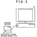
- FIG. 5 shows one practical use example in which data transfer is started in response to the operation of “bringing closer” for an apparatus.
- each of a digital camera and a cradle includes a UWB wireless device.
- the cradle is coupled to a television or personal computer via a cable, and transfers image data by use of UWB short-range communication.
- the digital camera By disposing the digital camera on the cradle, they can be fixed with such a short distance therebetween that high-transmission-rate and high-quality transmission is allowed therebetween.
- the digital camera After still images and moving images are captured by the digital camera, the digital camera is set to the cradle. Subsequently, in accordance with a processing procedure like one shown in FIG. 4 , the data of the images is transmitted from the digital camera to the cradle by UWB communication, followed by being transferred from the cradle to the television or personal computer.
- FIG. 6 shows another practical use example in which data transfer is started in response to the operation of “bringing closer-” for an apparatus.
- each of a digital audio player and a cradle includes a UWB wireless device.
- the cradle is coupled to a personal computer via a cable, and transfers music data.
- each of a digital audio player and a music distribution terminal includes a UWB wireless device, and music data is transferred therebetween.
- the former system by disposing the digital audio player on the cradle, they can be fixed with such a short distance therebetween that high-transmission-rate and high-quality transmission is allowed therebetween.
- music data Stored in the personal computer and music distribution terminal is music data that can be reproduced by the digital audio player.
- the digital audio player is set to the cradle, or is brought closer to the music distribution terminal.
- music data is transmitted from the personal computer to the digital audio player via the cradle by UWB communication.
- the music data is directly transmitted from the music distribution terminal to the digital audio player. It should be obvious that not only the music data but also game data and other data can be transferred.
- the apparatuses each including a UWB wireless device are often brought close to each other so that the distance therebetween becomes 10 mm or less, or so that the casings of the apparatuses are brought into contact with each other. Therefore, the antenna used in the UWB wireless device should be small enough to be contained in the apparatus. In addition, the antenna needs to have such a wideband property as to be capable of transmitting wireless signals of a transmission rate of 100 Mbps or more, and needs to maintain the property even in an ultra-short range.
- each of the antennas receives radio waves reflected by the ground layer of the opposite antenna, and therefore fails to obtain favorable characteristics regarding both the reflection characteristic and coupling characteristic. Furthermore, in electromagnetic waves in a near field within one wavelength from the generation source of the electromagnetic waves, the electric field and magnetic field are independent of each other, and hence the space impedance does not take a constant value. Accordingly, it is difficult to design an antenna so that desired properties are achieved in the operating frequency band.
- patch antennas and slot antennas have been known.
- both are basically a narrowband antenna of which operating band is about several percentages, and therefore widening of the band should be achieved.
- the slot antenna can offer a wider band than the patch antenna if the sizes of the both are the same. Therefore, the present inventor considers that the slot antenna is more suitable as an ultra-short-range UWB antenna used in a consumer apparatus.
- FIG. 7 illustrates the surface structure of a slot antenna that can be applied to the data transfer system according to the embodiment of the present invention.
- the slot antenna shown in the drawing includes a dielectric substrate 301 , a conductive pattern 306 formed on one face of the dielectric substrate 301 , and a ground layer 302 formed on the other face of the dielectric substrate 301 .
- the dielectric substrate 301 is composed of e.g. a material called FR4, and has a dielectric constant ⁇ of 4.2 to 4.8.
- the conductive pattern 306 is made up of a copper foil pattern that is formed along the periphery of the one face of the dielectric substrate 301 .
- a large number of through holes penetrating the dielectric substrate 301 are formed into a ring shape. These through holes are filled so that the conductive pattern 306 is coupled to the ground layer 302 formed on the backside of the dielectric substrate 301 .
- the through holes are arranged with an interval of 4 mm.
- the microstrip line 304 is provided on the center line that halves the area of the rectangular dielectric substrate, and has a width of 1.2 mm for example.
- a pattern separation part having a width of 5 mm is provided near the end of the microstrip line 304 on the peripheral part, so that the copper foil pattern is adequately separated.
- the end of the microstrip line 304 on the peripheral part is located at substantially the center of the pattern separation part for the conductive pattern 306 , and serves as a power feed point 303 for the conductive pattern 306 .
- the ground layer 302 is made up of a copper foil pattern that is formed on almost the entire face of the dielectric substrate 301 opposite to the face having the conductive pattern 306 thereon.
- a thin-line pattern is opened in substantially the center of the ground layer 302 so as to form a slot 305 .
- the slot 305 is substantially perpendicular to the extension direction of the microstrip line 304 , which is formed on the opposite face.
- the basic operational principle of the slot antenna is that an electromagnetic field is discharged mainly from the slot. Specifically, when power is fed to the microstrip line 304 via the power feed point 303 , an electromagnetic field is discharged from the slot 305 and thus an electric field traversing the slot 305 is formed. This electric field produces stationary waves to resonate.
- the slot 305 opened in the ground layer 302 is disposed in such a manner as to traverse the center line of the substrate passing through the power feed point 303 . It is preferable that the specific layout of the slot 305 , i.e., the lateral lengths from the power feed point 305 and the width, be optimized so that stable antenna properties are achieved.
- the slot 305 has a width of 1 mm, and a total length of 37.5 mm. Furthermore, the slot 305 ranges from the position apart from the center of the ground layer 302 by 21 mm to the position apart from the center by 16. 5 mm.
- electric resistors 107 are mounted on the slot 305 opened in the ground layer 302 .
- the electric resistors 307 have a resistance value of e.g. 100 ⁇ or more, and are disposed so that both the ends thereof are connected to the ground layer 302 .
- the electric resistors 307 have an effect of suppressing reflection at the ground layer 302 to thereby exploit a wideband characteristic.
- two electric resistors 307 are mounted at adequate positions near the center of the slot 305 . Thus, flexibility in adjustment of the impedance match is achieved, and the antenna properties can be improved.
- the slot antenna shown in FIG. 7 When the slot antenna shown in FIG. 7 is applied as a built-in antenna in an apparatus, there is a need to remove influence of electromagnetic waves from peripheral circuits in the apparatus and influence of reflectors around the apparatus. Furthermore, there is also a need to consider influence given to peripheral high-frequency circuits by high-frequency components of the emitted wideband waves. Therefore, when the slot antenna is incorporated into a consumer apparatus or the like, a metal shield case (not shown) covering the conductive pattern 306 may be provided.
- an antenna is incorporated into a portable apparatus such as a small digital camera or music player, the situation in which communication is carried out while the apparatus is grasped by a user's hand is possible. Furthermore, when a small apparatus is provided with a wireless communication function, circuits other than an antenna are also incorporated into the apparatus. Even if communication is implemented while the environment around the antenna is changing, and metal reflectors exist around the apparatus, the provision of a metal shield case allows stable achievement of desired antenna properties.
- Main purposes of the slot antenna shown in FIG. 7 are to be used with being included in a consumer apparatus as e.g. a low band (3.1 to 4.9 GHz) UWB antenna, and to be applied to wireless data transmission across an ultra-short distance.
- the antenna needs to be designed so that the following requirements are satisfied: the reflection characteristic is such that the reflection coefficient is lower than ⁇ 10 dB in a wideband of the predetermined specification; there is no sharp gain attenuation in the coupling characteristic; and the entire gain is higher than a certain level.
- FIG. 8 shows simulation results about S-parameters of the ultra-short-range UWB antennas shown in FIG. 7 that are separated from each other by 5 mm.
- the reflection coefficient is under ⁇ 10 dB and the propagation loss is as high as ⁇ 20 dB in a band of 3.1 to 4.9 GHz, which is the use band of the UWB low band.
- transmission in the maximum transmission rate mode 500 Mbps is possible in a range of the propagation loss up to ⁇ 64 dB.
- FIG. 9 shows simulation results about S-parameters of the ultra-short-range UWB antennas shown in FIG. 7 that are separated from each other by 10 mm. As is apparent from FIG. 9 , also when the distance between the antennas is 10 mm, the reflection coefficient is lower than ⁇ 10 dB, and a favorable coupling characteristic is achieved similarly.
- antennas having the same structure are used as a coupler (one pair) for transmission and reception, influence when the slots 305 of both the slot antennas are not opposed to each other is of concern. However, it has been confirmed that similar antenna properties can be obtained even when there is an offset of the orientation direction and angle of the antennas.
- UWB wireless signal transmission can be implemented without suffering from deterioration of antenna properties even when the terminals for communication are very close to each other. Furthermore, since antenna properties are ensured even when the terminals are close to each other, transmission with a small propagation loss and a high transmission rate is possible.
- the gist of the invention is not limited thereto.
- the present invention can be similarly applied to a system in which mobile or consumer apparatuses that each include a UWB wireless device and are close to each other transmit high-capacity data by wireless at a high speed and with a high quality.
Abstract
Description
Claims (17)
Priority Applications (1)
| Application Number | Priority Date | Filing Date | Title |
|---|---|---|---|
| US11/544,761 US8126035B2 (en) | 2005-08-18 | 2006-10-10 | Data transfer system, wireless communication device, wireless communication method, and computer program |
Applications Claiming Priority (2)
| Application Number | Priority Date | Filing Date | Title |
|---|---|---|---|
| JP2005-238018 | 2005-08-18 | ||
| JP2005238018 | 2005-08-18 |
Related Child Applications (1)
| Application Number | Title | Priority Date | Filing Date |
|---|---|---|---|
| US11/544,761 Continuation-In-Part US8126035B2 (en) | 2005-08-18 | 2006-10-10 | Data transfer system, wireless communication device, wireless communication method, and computer program |
Publications (2)
| Publication Number | Publication Date |
|---|---|
| US20070041426A1 US20070041426A1 (en) | 2007-02-22 |
| US7706432B2 true US7706432B2 (en) | 2010-04-27 |
Family
ID=37767281
Family Applications (2)
| Application Number | Title | Priority Date | Filing Date |
|---|---|---|---|
| US11/496,430 Expired - Fee Related US7706432B2 (en) | 2005-08-18 | 2006-08-01 | Data transfer system, wireless communication device, wireless communication method, and computer program |
| US11/544,761 Expired - Fee Related US8126035B2 (en) | 2005-08-18 | 2006-10-10 | Data transfer system, wireless communication device, wireless communication method, and computer program |
Family Applications After (1)
| Application Number | Title | Priority Date | Filing Date |
|---|---|---|---|
| US11/544,761 Expired - Fee Related US8126035B2 (en) | 2005-08-18 | 2006-10-10 | Data transfer system, wireless communication device, wireless communication method, and computer program |
Country Status (3)
| Country | Link |
|---|---|
| US (2) | US7706432B2 (en) |
| JP (1) | JP2008178114A (en) |
| CN (1) | CN101243636A (en) |
Cited By (4)
| Publication number | Priority date | Publication date | Assignee | Title |
|---|---|---|---|---|
| US20070149124A1 (en) * | 2005-11-30 | 2007-06-28 | Katsuyuki Onozawa | Wireless communication device |
| US8140015B2 (en) | 2009-01-16 | 2012-03-20 | Kabushiki Kaisha Toshiba | Electronic apparatus and communication state notification function control method |
| US20150091702A1 (en) * | 2013-09-27 | 2015-04-02 | Qualcomm Incorporated | Power efficient and flexible update rate positioning system |
| US11960016B2 (en) | 2021-10-15 | 2024-04-16 | Hyundai Mobis Co., Ltd. | Apparatus and method for detecting location of UWB module installed in vehicle |
Families Citing this family (28)
| Publication number | Priority date | Publication date | Assignee | Title |
|---|---|---|---|---|
| KR20080106759A (en) * | 2007-06-04 | 2008-12-09 | 삼성전자주식회사 | Video signal processing apparatus and display apparatus and video signal processing method |
| JP4987586B2 (en) * | 2007-06-22 | 2012-07-25 | 株式会社東芝 | Information processing apparatus and control method |
| US9019934B2 (en) * | 2007-10-24 | 2015-04-28 | Hmicro, Inc. | Systems and networks for half and full duplex wireless communication using multiple radios |
| US7830817B1 (en) | 2007-12-05 | 2010-11-09 | Sprint Spectrum L.P. | Vocoder selection based on location of client device |
| WO2009100401A2 (en) * | 2008-02-06 | 2009-08-13 | Hmicro, Inc. | Wireless communications systems using multiple radios |
| EP2357566B1 (en) * | 2008-11-17 | 2018-02-21 | Sony Interactive Entertainment Inc. | Radio communication terminal, method for controlling the same, and information storage medium |
| CN101944959A (en) * | 2010-07-01 | 2011-01-12 | 北京泛在电子标签技术有限公司 | Wireless short distance communication method and system based on distance control |
| CN102412869B (en) * | 2010-09-21 | 2014-05-28 | 国民技术股份有限公司 | System and method for fast accessing near field communication with controllable communication range |
| CN102412870A (en) * | 2010-09-21 | 2012-04-11 | 国民技术股份有限公司 | Fast-access near field wireless communication module used for controlling communication range |
| US20130217334A1 (en) * | 2010-09-21 | 2013-08-22 | Nationz Technologies Inc. | Fast access short-range communication system and method |
| KR101702361B1 (en) * | 2010-11-03 | 2017-02-03 | 삼성전자주식회사 | Method and apparatus for connecting wireless network in a digital device |
| JP5664332B2 (en) | 2011-02-25 | 2015-02-04 | 富士通株式会社 | Support device and system |
| CN102957484A (en) * | 2011-08-18 | 2013-03-06 | 国民技术股份有限公司 | Method and device for implementing communication within safe distance by real-time radiofrequency detection |
| JP5855924B2 (en) * | 2011-12-09 | 2016-02-09 | 桑原 雅人 | Server apparatus, communication system, control method, and program |
| CN106162947B (en) | 2012-02-10 | 2020-02-14 | 日本电气株式会社 | Base station system |
| WO2014142818A1 (en) | 2013-03-13 | 2014-09-18 | Intel Corporation | Sharing information between computing devices |
| US9596560B2 (en) * | 2013-06-20 | 2017-03-14 | Fossil Group, Inc. | Systems and methods for data transfer |
| US11814088B2 (en) | 2013-09-03 | 2023-11-14 | Metrom Rail, Llc | Vehicle host interface module (vHIM) based braking solutions |
| US9921657B2 (en) * | 2014-03-28 | 2018-03-20 | Intel Corporation | Radar-based gesture recognition |
| WO2016163923A1 (en) * | 2015-04-07 | 2016-10-13 | Nidatech Sweden Ab | Enhanced time of arrival positioning system |
| WO2017145789A1 (en) * | 2016-02-26 | 2017-08-31 | ソニー株式会社 | Positioning device, communication device and positioning system |
| US11349589B2 (en) | 2017-08-04 | 2022-05-31 | Metrom Rail, Llc | Methods and systems for decentralized rail signaling and positive train control |
| KR102499917B1 (en) * | 2017-12-07 | 2023-02-16 | 삼성전자주식회사 | Electronic device performing positioning and method for controlling thereof |
| DE102020101733A1 (en) | 2020-01-24 | 2021-07-29 | Bundesdruckerei Gmbh | Authorization management using UWB tokens |
| CN111536913B (en) * | 2020-04-24 | 2022-02-15 | 芜湖职业技术学院 | House layout graph measuring device and measuring method thereof |
| CN112243290B (en) * | 2020-10-19 | 2023-05-23 | Oppo广东移动通信有限公司 | WIFI transmitting power adjustment method, device, equipment and medium |
| CN112291708B (en) * | 2020-11-27 | 2023-06-23 | 歌尔科技有限公司 | Data transmission method, device, equipment and computer readable storage medium |
| WO2023050332A1 (en) * | 2021-09-30 | 2023-04-06 | 华为技术有限公司 | Ranging rate switching control method and communication apparatus |
Citations (13)
| Publication number | Priority date | Publication date | Assignee | Title |
|---|---|---|---|---|
| JP2001506066A (en) | 1996-10-29 | 2001-05-08 | クゥアルコム・インコーポレイテッド | Method and apparatus for high-speed data communication in a mobile phone environment |
| JP2002204239A (en) | 2000-10-24 | 2002-07-19 | Sony Corp | Device and method for information processing, electronic equipment, information processing system, and recording medium |
| US20030220765A1 (en) * | 2002-05-24 | 2003-11-27 | Overy Michael Robert | Method and apparatus for enhancing security in a wireless network using distance measurement techniques |
| JP2004015179A (en) | 2002-06-04 | 2004-01-15 | Fujitsu Ltd | Wireless apparatus mounted with impedance matching unit corresponding to a plurality of antennas |
| WO2004038959A1 (en) | 2002-10-28 | 2004-05-06 | Siemens Aktiengesellschaft | Method for decentralised synchronisation in a self-organising radio communication system |
| JP2004151179A (en) | 2002-10-29 | 2004-05-27 | Kyocera Corp | Optical thin film filter |
| JP2004258009A (en) | 2003-02-28 | 2004-09-16 | Sony Corp | Range-finding/positioning system, range-finding/ positioning method, and radio communication device |
| JP2004298815A (en) | 2003-04-01 | 2004-10-28 | Inoue Kinzoku Kogyo Co Ltd | Coating method and coating apparatus |
| JP2005086531A (en) | 2003-09-09 | 2005-03-31 | Sony Corp | Wireless communication unit |
| JP2005130292A (en) | 2003-10-24 | 2005-05-19 | Ykc:Kk | Ultra-wideband antenna and ultra-wideband high-frequency module |
| JP2005136897A (en) | 2003-10-31 | 2005-05-26 | Sony Corp | Communication system, information processing apparatus and method, and program |
| US20050169232A1 (en) * | 2003-10-24 | 2005-08-04 | Sony Corporation | Wireless communication system, wireless communication device and wireless communication method, and computer program |
| US20050288003A1 (en) * | 2004-06-29 | 2005-12-29 | Kabushiki Kaisha Toshiba | Wireless communication system and communication terminal |
Family Cites Families (6)
| Publication number | Priority date | Publication date | Assignee | Title |
|---|---|---|---|---|
| US6111536A (en) | 1998-05-26 | 2000-08-29 | Time Domain Corporation | System and method for distance measurement by inphase and quadrature signals in a radio system |
| US6937667B1 (en) | 2000-03-29 | 2005-08-30 | Time Domain Corporation | Apparatus, system and method for flip modulation in an impulse radio communications system |
| US8127326B2 (en) * | 2000-11-14 | 2012-02-28 | Claussen Paul J | Proximity detection using wireless connectivity in a communications system |
| JP2003224569A (en) | 2002-01-29 | 2003-08-08 | Sharp Corp | Radio communication system |
| US20050147130A1 (en) * | 2003-12-23 | 2005-07-07 | Intel Corporation | Priority based synchronization of data in a personal area network |
| GB0428046D0 (en) * | 2004-12-22 | 2005-01-26 | Artimi Ltd | Contactless connector systems |
-
2006
- 2006-08-01 US US11/496,430 patent/US7706432B2/en not_active Expired - Fee Related
- 2006-08-14 CN CNA2006800301252A patent/CN101243636A/en active Pending
- 2006-10-10 US US11/544,761 patent/US8126035B2/en not_active Expired - Fee Related
-
2008
- 2008-01-31 JP JP2008020251A patent/JP2008178114A/en active Pending
Patent Citations (18)
| Publication number | Priority date | Publication date | Assignee | Title |
|---|---|---|---|---|
| US6496543B1 (en) | 1996-10-29 | 2002-12-17 | Qualcomm Incorporated | Method and apparatus for providing high speed data communications in a cellular environment |
| JP2001506066A (en) | 1996-10-29 | 2001-05-08 | クゥアルコム・インコーポレイテッド | Method and apparatus for high-speed data communication in a mobile phone environment |
| US20060194541A1 (en) | 2000-10-24 | 2006-08-31 | Sony Corporation | Information processing apparatus and information processing method having communication function |
| JP2002204239A (en) | 2000-10-24 | 2002-07-19 | Sony Corp | Device and method for information processing, electronic equipment, information processing system, and recording medium |
| US7139529B2 (en) | 2000-10-24 | 2006-11-21 | Sony Corporation | Information processing method and information processing apparatus having communication function |
| US20030220765A1 (en) * | 2002-05-24 | 2003-11-27 | Overy Michael Robert | Method and apparatus for enhancing security in a wireless network using distance measurement techniques |
| JP2004015179A (en) | 2002-06-04 | 2004-01-15 | Fujitsu Ltd | Wireless apparatus mounted with impedance matching unit corresponding to a plurality of antennas |
| WO2004038959A1 (en) | 2002-10-28 | 2004-05-06 | Siemens Aktiengesellschaft | Method for decentralised synchronisation in a self-organising radio communication system |
| JP2004151179A (en) | 2002-10-29 | 2004-05-27 | Kyocera Corp | Optical thin film filter |
| JP2004258009A (en) | 2003-02-28 | 2004-09-16 | Sony Corp | Range-finding/positioning system, range-finding/ positioning method, and radio communication device |
| US20040235499A1 (en) | 2003-02-28 | 2004-11-25 | Sony Corporation | Ranging and positioning system, ranging and positioning method, and radio communication apparatus |
| JP2004298815A (en) | 2003-04-01 | 2004-10-28 | Inoue Kinzoku Kogyo Co Ltd | Coating method and coating apparatus |
| JP2005086531A (en) | 2003-09-09 | 2005-03-31 | Sony Corp | Wireless communication unit |
| US20050169232A1 (en) * | 2003-10-24 | 2005-08-04 | Sony Corporation | Wireless communication system, wireless communication device and wireless communication method, and computer program |
| JP2005130292A (en) | 2003-10-24 | 2005-05-19 | Ykc:Kk | Ultra-wideband antenna and ultra-wideband high-frequency module |
| JP2005136897A (en) | 2003-10-31 | 2005-05-26 | Sony Corp | Communication system, information processing apparatus and method, and program |
| US20050117750A1 (en) | 2003-10-31 | 2005-06-02 | Junichi Rekimoto | Communication system, information processing apparatus, method and computer program |
| US20050288003A1 (en) * | 2004-06-29 | 2005-12-29 | Kabushiki Kaisha Toshiba | Wireless communication system and communication terminal |
Non-Patent Citations (2)
| Title |
|---|
| http://pcweb.mycom.co.jp/news/2002/09/03/10.html. |
| Nikkei Electronics Issue No. 2002.3.11, "Ubugoe wo ageru musen no kakumeiji Ultra Wideband" pp. 55 to 66. |
Cited By (7)
| Publication number | Priority date | Publication date | Assignee | Title |
|---|---|---|---|---|
| US20070149124A1 (en) * | 2005-11-30 | 2007-06-28 | Katsuyuki Onozawa | Wireless communication device |
| US8150449B2 (en) | 2005-11-30 | 2012-04-03 | Canon Kabushiki Kaisha | Wireless communication device |
| US8548519B2 (en) | 2005-11-30 | 2013-10-01 | Canon Kabushiki Kaisha | Wireless communication device |
| US8140015B2 (en) | 2009-01-16 | 2012-03-20 | Kabushiki Kaisha Toshiba | Electronic apparatus and communication state notification function control method |
| US8463187B2 (en) | 2009-01-16 | 2013-06-11 | Kabushiki Kaisha Toshiba | Electronic apparatus and communication state notification function control method |
| US20150091702A1 (en) * | 2013-09-27 | 2015-04-02 | Qualcomm Incorporated | Power efficient and flexible update rate positioning system |
| US11960016B2 (en) | 2021-10-15 | 2024-04-16 | Hyundai Mobis Co., Ltd. | Apparatus and method for detecting location of UWB module installed in vehicle |
Also Published As
| Publication number | Publication date |
|---|---|
| CN101243636A (en) | 2008-08-13 |
| JP2008178114A (en) | 2008-07-31 |
| US20070041426A1 (en) | 2007-02-22 |
| US20070053412A1 (en) | 2007-03-08 |
| US8126035B2 (en) | 2012-02-28 |
Similar Documents
| Publication | Publication Date | Title |
|---|---|---|
| US7706432B2 (en) | Data transfer system, wireless communication device, wireless communication method, and computer program | |
| EP1916791B1 (en) | Data transferring system, wireless communication apparatus, wireless communication method, and computer program | |
| US6507322B2 (en) | Space diversity slot antennas and apparatus using the same | |
| US8013795B2 (en) | Communication system and communication apparatus | |
| JP4915358B2 (en) | Power transmission device, power reception device, and power transmission system | |
| KR101091393B1 (en) | Antenna and radio communication unit | |
| JP5724439B2 (en) | Electronic devices and modules mounted on electronic devices | |
| US9478866B2 (en) | Orientation agnostic millimeter-wave radio link | |
| JP2008099236A (en) | Communication system, communication device, and high-frequency coupler | |
| JP2008182714A (en) | Communication system, communication apparatus, and high-frequency coupler | |
| US20050117545A1 (en) | RF circuitry and compact hybrid for wireless communication devices | |
| WO2020014363A1 (en) | Surface-link antenna architecture | |
| JP2007060127A (en) | Slot antenna | |
| US8212727B2 (en) | Antenna and wireless transceiver using the same | |
| US20160380346A1 (en) | Waveguide Structure | |
| JP4067041B2 (en) | Plate antenna and communication terminal equipped with the antenna | |
| US11962071B2 (en) | Electronic device provided with antenna | |
| JP2003037541A (en) | Wireless apparatus and wireless communication system | |
| JP2008311816A (en) | Communication device | |
| TW202341676A (en) | Gain pattern overlap reduction | |
| JP2006005498A (en) | System, device and method for radio communication and computer program | |
| JP2004227422A (en) | Wireless module device and communication device | |
| JP2007318616A (en) | Radio communication device, and information communication equipment |
Legal Events
| Date | Code | Title | Description |
|---|---|---|---|
| AS | Assignment |
Owner name: SONY CORPORATION,JAPAN Free format text: ASSIGNMENT OF ASSIGNORS INTEREST;ASSIGNOR:HASHIMOTO, YUHEI;REEL/FRAME:018382/0608 Effective date: 20061004 Owner name: SONY CORPORATION, JAPAN Free format text: ASSIGNMENT OF ASSIGNORS INTEREST;ASSIGNOR:HASHIMOTO, YUHEI;REEL/FRAME:018382/0608 Effective date: 20061004 |
|
| FEPP | Fee payment procedure |
Free format text: PAYOR NUMBER ASSIGNED (ORIGINAL EVENT CODE: ASPN); ENTITY STATUS OF PATENT OWNER: LARGE ENTITY |
|
| FEPP | Fee payment procedure |
Free format text: PAYOR NUMBER ASSIGNED (ORIGINAL EVENT CODE: ASPN); ENTITY STATUS OF PATENT OWNER: LARGE ENTITY Free format text: PAYER NUMBER DE-ASSIGNED (ORIGINAL EVENT CODE: RMPN); ENTITY STATUS OF PATENT OWNER: LARGE ENTITY |
|
| STCF | Information on status: patent grant |
Free format text: PATENTED CASE |
|
| FPAY | Fee payment |
Year of fee payment: 4 |
|
| MAFP | Maintenance fee payment |
Free format text: PAYMENT OF MAINTENANCE FEE, 8TH YEAR, LARGE ENTITY (ORIGINAL EVENT CODE: M1552) Year of fee payment: 8 |
|
| FEPP | Fee payment procedure |
Free format text: MAINTENANCE FEE REMINDER MAILED (ORIGINAL EVENT CODE: REM.); ENTITY STATUS OF PATENT OWNER: LARGE ENTITY |
|
| LAPS | Lapse for failure to pay maintenance fees |
Free format text: PATENT EXPIRED FOR FAILURE TO PAY MAINTENANCE FEES (ORIGINAL EVENT CODE: EXP.); ENTITY STATUS OF PATENT OWNER: LARGE ENTITY |
|
| STCH | Information on status: patent discontinuation |
Free format text: PATENT EXPIRED DUE TO NONPAYMENT OF MAINTENANCE FEES UNDER 37 CFR 1.362 |
|
| FP | Lapsed due to failure to pay maintenance fee |
Effective date: 20220427 |