US7760701B2 - Arrangement in a router for distributing a routing rule used to generate routes based on a pattern of a received packet - Google Patents
Arrangement in a router for distributing a routing rule used to generate routes based on a pattern of a received packet Download PDFInfo
- Publication number
- US7760701B2 US7760701B2 US10/429,851 US42985103A US7760701B2 US 7760701 B2 US7760701 B2 US 7760701B2 US 42985103 A US42985103 A US 42985103A US 7760701 B2 US7760701 B2 US 7760701B2
- Authority
- US
- United States
- Prior art keywords
- address
- router
- routing
- gateway
- prescribed
- Prior art date
- Legal status (The legal status is an assumption and is not a legal conclusion. Google has not performed a legal analysis and makes no representation as to the accuracy of the status listed.)
- Expired - Fee Related, expires
Links
Images


Classifications
-
- H—ELECTRICITY
- H04—ELECTRIC COMMUNICATION TECHNIQUE
- H04L—TRANSMISSION OF DIGITAL INFORMATION, e.g. TELEGRAPHIC COMMUNICATION
- H04L45/00—Routing or path finding of packets in data switching networks
- H04L45/56—Routing software
- H04L45/566—Routing instructions carried by the data packet, e.g. active networks
-
- H—ELECTRICITY
- H04—ELECTRIC COMMUNICATION TECHNIQUE
- H04L—TRANSMISSION OF DIGITAL INFORMATION, e.g. TELEGRAPHIC COMMUNICATION
- H04L45/00—Routing or path finding of packets in data switching networks
- H04L45/02—Topology update or discovery
-
- H—ELECTRICITY
- H04—ELECTRIC COMMUNICATION TECHNIQUE
- H04L—TRANSMISSION OF DIGITAL INFORMATION, e.g. TELEGRAPHIC COMMUNICATION
- H04L45/00—Routing or path finding of packets in data switching networks
- H04L45/02—Topology update or discovery
- H04L45/025—Updating only a limited number of routers, e.g. fish-eye update
-
- H—ELECTRICITY
- H04—ELECTRIC COMMUNICATION TECHNIQUE
- H04L—TRANSMISSION OF DIGITAL INFORMATION, e.g. TELEGRAPHIC COMMUNICATION
- H04L45/00—Routing or path finding of packets in data switching networks
- H04L45/02—Topology update or discovery
- H04L45/033—Topology update or discovery by updating distance vector protocols
-
- H—ELECTRICITY
- H04—ELECTRIC COMMUNICATION TECHNIQUE
- H04L—TRANSMISSION OF DIGITAL INFORMATION, e.g. TELEGRAPHIC COMMUNICATION
- H04L45/00—Routing or path finding of packets in data switching networks
- H04L45/54—Organization of routing tables
-
- H—ELECTRICITY
- H04—ELECTRIC COMMUNICATION TECHNIQUE
- H04L—TRANSMISSION OF DIGITAL INFORMATION, e.g. TELEGRAPHIC COMMUNICATION
- H04L45/00—Routing or path finding of packets in data switching networks
- H04L45/74—Address processing for routing
- H04L45/745—Address table lookup; Address filtering
- H04L45/74591—Address table lookup; Address filtering using content-addressable memories [CAM]
-
- H—ELECTRICITY
- H04—ELECTRIC COMMUNICATION TECHNIQUE
- H04L—TRANSMISSION OF DIGITAL INFORMATION, e.g. TELEGRAPHIC COMMUNICATION
- H04L61/00—Network arrangements, protocols or services for addressing or naming
-
- H—ELECTRICITY
- H04—ELECTRIC COMMUNICATION TECHNIQUE
- H04L—TRANSMISSION OF DIGITAL INFORMATION, e.g. TELEGRAPHIC COMMUNICATION
- H04L61/00—Network arrangements, protocols or services for addressing or naming
- H04L61/35—Network arrangements, protocols or services for addressing or naming involving non-standard use of addresses for implementing network functionalities, e.g. coding subscription information within the address or functional addressing, i.e. assigning an address to a function
-
- H—ELECTRICITY
- H04—ELECTRIC COMMUNICATION TECHNIQUE
- H04W—WIRELESS COMMUNICATION NETWORKS
- H04W8/00—Network data management
- H04W8/02—Processing of mobility data, e.g. registration information at HLR [Home Location Register] or VLR [Visitor Location Register]; Transfer of mobility data, e.g. between HLR, VLR or external networks
- H04W8/08—Mobility data transfer
- H04W8/087—Mobility data transfer for preserving data network PoA address despite hand-offs
Definitions
- the present invention relates to distribution of routing information by an Internet Protocol (IP) based router that enables aggregation of routes in another IP router.
- IP Internet Protocol
- Routing protocols are used to exchange routing information between networks, allowing routing tables to be built dynamically.
- Traditional Internet Protocol (IP) based routing uses next-hop routing, where a router only needs to consider where it sends the packet, and does not need to consider the subsequent path of the packet on the remaining hops. This form of dynamic routing provides substantial flexibility in the Internet, and has enabled the Internet to grow in size by more than eight orders of magnitude over the last thirty years.
- IP Internet Protocol
- Link-state routing protocols enable a router to inform other routers of its “neighbors” (i.e., adjacent routers).
- Distance-vector routing protocols enable a router to describe the network topology to its “neighbors”.
- IP Internet Protocol
- MANET Mobile Ad-hoc Networks
- NEMO mobile networks
- MIP Mobile IP
- the “mobile ad hoc network” is an autonomous system of mobile routers (and associated hosts) connected by wireless links—the union of which form an arbitrary graph.
- the routers are free to move randomly and organize themselves arbitrarily; thus, the network's wireless topology may change rapidly and unpredictably.
- Such a network may operate in a standalone fashion, or may be connected to the larger Internet.
- a “Mobile IPv6” protocol is disclosed in an Internet Draft by Johnson et al., entitled “Mobility Support in IPv6”, available on the World Wide Web at the address: http://www.ietf.org/internet-drafts/draft-ietf-mobileip-ipv6-20.txt (the disclosure of which is incorporated in its entirety herein by reference).
- the Mobile IPv6 protocol enables a mobile node to move from one link to another without changing the mobile node's IP address.
- the mobile node is assigned a “home address”.
- the “home address” is an IP address assigned to the mobile node within its home subnet prefix on its home link. While a mobile node is at home, packets addressed to its home address are routed to the mobile node's home link, using conventional Internet routing mechanisms.
- the mobile node also is assigned a home agent for registering any care-of address used by the mobile node at its point of attachment to the Internet while the mobile node is away from its home link.
- a care-of address is an IP address associated with a mobile node that has the subnet prefix of a particular link away from its home link (i.e., a foreign link).
- a home agent is a router on a mobile node's home link with which the mobile node has registered its current care-of address. While the mobile node is away from its home link, the home agent intercepts packets on the home link destined to the mobile node's home address; the home agent encapsulates the packets, and tunnels the packets to the mobile node's registered care-of address.
- a mobile node is always addressable by its “home address”: packets may be routed to the mobile node using this address regardless of the mobile node's current point of attachment to the Internet.
- the mobile node also may continue to communicate with other nodes (stationary or mobile) after moving to a new link. The movement of a mobile node away from its home link is thus transparent to transport and higher-layer protocols and applications.
- routers in a conventional Internet-based network topology are configured for aggregating routes based on groupings of subnets according to a hierarchy of common addresses.
- a top-level router e.g., a primary router of an organization configured as an entry point to the organization for all Internet traffic
- the top-level router includes a routing table that includes including routing entries. Each routing entry includes a corresponding prefix key and a next hop field.
- the prefix key is used to match the destination address of an incoming packet (typically applying a net mask to the destination address); hence, the router identifies the entry having the corresponding prefix key that matches the masked destination address, and routes the packet to the router specified in the corresponding next hop field.
- a single router may aggregate multiple routes for reaching routers configured for serving the subnets having subnet address prefix values within the aggregated value of 127/8 (e.g., 127.192/10, 127.192/10, 127.192/10, and 127.192/10, etc.).
- Each subnet typically will include additional routers configured for routing packets within the corresponding prescribed address space.
- the home agent would require a routing table entry for each mobile prefix via a mobile router that serves as a point of attachment for a corresponding mobile network.
- IP Internet Protocol
- a router is configured for sharing routing rules with other routers, the routing rules defining aggregated routes according to a prescribed topology.
- Each routing rule used by the router for routing a packet having a corresponding matching destination address prefix, specifies a corresponding address prefix pattern rule for extracting an identified pattern from a portion of the destination address, and a gateway address pattern rule for generating a gateway address, for a gateway providing reachability to the destination address, based on applying the identified pattern to a specified portion of the gateway address.
- the router generates a routing update message that describes the address prefix pattern rule and the gateway address pattern rule, and outputs the routing update message to a second router according to a prescribed routing protocol.
- the second router can route a packet according to the prescribed topology used by the routing rule.
- IP Internet Protocol
- the method includes storing a routing rule that defines routes aggregated according to a prescribed topology.
- the routing rule specifies an address prefix pattern rule for extracting an identified pattern from a first portion of a destination address, and a gateway address pattern rule for generating a gateway address based on applying the identified pattern to a specified second portion of the gateway address.
- the gateway address specifies a gateway providing reachability to the destination address.
- the method also includes generating a routing update message that describes the address prefix pattern rule and the gateway address pattern rule, outputting the routing update message to a second router according to a prescribed routing protocol. The second router is able to use the routing update message in routing a corresponding received packet according to the prescribed topology.
- the router includes a table, a routing protocol resource, and an IP interface.
- the table is configured for storing a routing rule that defines routes aggregated according to a prescribed topology.
- the routing rule specifies an address prefix pattern rule for extracting an identified pattern from a first portion of a destination address, and a gateway address pattern rule for generating a gateway address, specifying a gateway providing reachability to the destination address, based on applying the identified pattern to a specified second portion of the gateway address.
- the routing protocol resource is configured generating a routing update message, that describes the address prefix pattern rule and the gateway address pattern rule, for use by a second router in routing a corresponding received packet according to the prescribed topology.
- the IP interface is configured for outputting the routing update message to the second router according to a prescribed routing protocol.
- FIG. 1 is a diagram illustrating a routing table configured for generating pattern-based automatic routes, according to an embodiment of the present invention.
- FIG. 2 is a diagram illustrating the method of generating a route based on the route table entry of FIG. 1 .
- FIG. 3 is a diagram illustrating the transfer of pattern-based automatic routes between route servers and route-server clients, according to an embodiment of the present invention.
- FIG. 4 is a diagram illustrating deployment of the route servers and route server-clients of FIG. 3 in a wide area network, including a mobile networks having respective mobile routers in communication with a prescribed home agent within, wherein the home agent includes a routing table for pattern-based automatic routes according to an embodiment of the present invention.
- FIG. 5 is a diagram illustrating in detail the home agent of FIG. 4 .
- FIG. 6 is a diagram illustrating an exemplary function from the routing field of FIG. 5 , used to calculate the home address of the via router of FIG. 4 .
- FIG. 7 is a diagram illustrating the method of generating the address for the via router, according to an embodiment of the present invention.
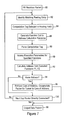
- FIG. 8 is a diagram illustrating the method by a router of outputting, to a second router, a routing update message specifying a routing rule for generating an pattern-based automatic route, according to an embodiment of the present invention.
- FIG. 9 is a diagram illustrating the method of receiving a routing update message and in response implementing the routing rule for generating the pattern-based automatic route, according to an embodiment of the present invention.
- the disclosed embodiment is directed to a router configured for distributing routing update messages that specify routing rules for generating pattern-based automatic routes, enabling different routers within a wide area network to share routing rules for aggregation of routes within the respective routers.
- the router is configured for determining a “via” router (e.g., the IPv6 mobile router) for a received packet based on accessing a routing table having multiple routing entries: each routing entry includes a routing key and a routing field that specifies either a prescribed address specifying the via router or a computation tag, also referred to herein as a routing rule.
- the via router is a router within the path to a destination node, and will be able to route the packet along the path.
- the computation tag i.e., routing rule
- the router identifies, for each received packet, the matching routing entry based on the corresponding routing key, and in response to detecting the computation tag in the routing field, selectively executes the corresponding function to calculate the determined address for the via router.
- the attributes associated with the above-described computation tag are distributed to other routers using a prescribed distance vector routing protocol, enabling other routers to use the routing rule for their own routing operations.
- routing rules enables other routers to automatically establish optimized routes between subnetworks in a scaleable manner, where the optimized routes between subnetworks can be established using a single routing rule.
- a description will be provided of the routing operations based on generation of pattern-based automatic routes using the routing rules, as well as the arrangement for distributing the routing rules to other routers. A description also will be provided of how a router, having received the routing rule, can implement the rule to provide route optimization in a scaleable manner.
- FIG. 1 is a diagram illustrating a routing table 102 configured for generating pattern-based automatic routes using routing rules, according to an embodiment of the present invention.
- the routing table 102 includes a prefix field 104 that specifies a prefix key P, also referred to as a routing key, a routing field 106 that specifies a rule (e.g., a prescribed function) R, and a parameter field 108 that specifies parameters (p) for execution of the rule R according to the function R(D, packet, P, p).
- the next hop gateway address is obtained by execution of the function R(D, packet, P, p).
- the “routing rule” includes information from the routing field 106 and the parameter field 108 .
- FIG. 2 is a diagram illustrating the method of generating a route based on the route table entry of FIG. 1 .
- a router having the routing table 102 extracts in step 112 from the received packet the destination address D, and a prescribed parameter list L (e.g., explicit header values specified in the received packet).
- the router executes in step 114 a best-match algorithm search against the routing table 102 , using the destination address D as a key, in order to locate in step 116 a matching entry (Entry “E”) 118 .
- the router retrieves in step 120 the corresponding prefix P from the prefix field 104 , the corresponding rule R from the routing field 106 , and the corresponding parameter list p from the parameters field 108 .
- the router computes in step 122 the gateway address G based on executing the function R based on the destination address D, the parameters P from the received packet, the matching address prefix P from the prefix field 104 , and/or the corresponding stored parameters p from the parameter field 108 .
- the router performs in step 124 a recursive lookup in the routing table 102 (e.g., repeat steps 114 through 122 using the gateway address) to obtain the next hop router to reach the gateway.
- the packet is then forwarded to the next hop router (NH) in step 126 .
- router entries can be simplified based on storing routing rules specifying prescribed functions for calculating the destination address. Moreover, these route entries are distributed among different routers according to a prescribed routing protocol, enabling the routers to route received packets based on calculating the destination address.
- FIG. 3 is a diagram illustrating the distribution of routing rules among different network nodes, according to an embodiment of the present invention.
- the network 300 includes an ingress router 302 that receives a packet for transfer, an egress router 304 that serves as a via router for the received packet, and route servers 306 a and 306 b .
- the route servers 306 a and 306 b may be implemented as routers that also perform routing of packets.
- the ingress router 302 is configured for receiving routing information from the route server 306 a , for routing the packet directly via the path 308 b .
- the ingress route server 306 a receives routing rules from the egress route server 306 b , enabling the ingress route server 306 a to generate routing information for use by the ingress router 302 .
- the egress route server 306 b may be configured by an external source 310 with the routing rule, or may receive either the routing rule or other routing information from the egress router 304 using a prescribed routing protocol 312 a.
- the egress route server 306 b distributes the routing rule using a prescribed routing protocol 312 b to the ingress route server 306 a .
- the egress route server 306 b may distribute the routing rule in response to a request from the ingress route server 306 a (described below), or in response to detecting a threshold amount of traffic along the path 308 a.
- the ingress route server 306 a in response to receiving the routing rule from the egress route server 306 b according to the routing protocol 312 b , can then instantiate (i.e., generate, calculate) a complete route that explicitly specifies an IP address for reaching the egress router 304 via the path 308 b .
- the ingress route server 306 a may instantiate the complete route and supply the ingress router 302 with the complete route in response to a request from the ingress router 302 for an optimum route (based on the ingress router 302 detecting that the traffic is reaching a prescribed threshold).
- the ingress route server 306 a or egress route server 306 b also may instantiate the complete route based on its own corresponding detection that the traffic along path 308 a is exceeding a prescribed threshold, in which case the complete route would be supplied to the ingress router according to a routing protocol 312 c to direct the ingress router 302 to use the path 308 b.
- the supply of routing information may occur automatically by the egress route server 306 b “pushing” the routing rule to the ingress route server 306 a in response to detecting that traffic along the path 308 a exceeds a prescribed threshold; the ingress route server 306 a can then generate the complete routing information for the ingress router 302 to route packets via the path 308 b .
- the ingress route server 306 a may instantiate the routing information in response to a request from the ingress router 302 . In either case, the routing rules are distributed between the route servers 306 , which instantiate complete routes for routing packets.
- the disclosed arrangement for calculating the destination address using a rule specified in the routing table is particularly beneficial for mobile IP.
- FIG. 4 is a diagram illustrating a wide area network 10 having a router 12 configured for using a routing rule for calculating a determined address for routing of a received packet to a via router (e.g., 14 a 14 b , 14 c , etc.), and distributing that routing rule for use by other routers (e.g., 13 a , 13 b ) according to an embodiment of the present invention.
- a via router e.g., 14 a 14 b , 14 c , etc.
- FIG. 4 is a diagram illustrating a wide area network 10 having a router 12 configured for using a routing rule for calculating a determined address for routing of a received packet to a via router (e.g., 14 a 14 b , 14 c , etc.), and distributing that routing rule for use by other routers (e.g., 13 a , 13 b ) according to an embodiment of the present invention.
- FIG. 4 is a diagram illustrating a wide area
- the router 12 is implemented as a home agent (HA) and the via routers 14 a , 14 b , and 14 c are implemented as mobile routers serving as attachment points to the wide area network 10 for respective mobile networks 16 a , 16 b , and 16 c , in accordance with the above-incorporated Internet Draft by Johnson et al. Also note that the mobile router 14 d is currently at its home network 18 , where the mobile router 14 d has a home link 20 within the home network 18 to the home agent 12 .
- HA home agent
- the routers 13 a and 13 b also are configured as peer routers capable of exchanging routing information 15 between each other and the router 12 by specifying a new address family according to Multiprotocol Extension for Border Gateway Protocol (MP-BGP) as specified by the IETF Request for Comments (RFC) 2283, 2842, and 2858, incorporated in their entirety herein by reference.
- MP-BGP Multiprotocol Extension for Border Gateway Protocol
- the home network 18 has an IPv6 home subnet prefix value 28 of “ABCD::/64”, using the address notation specified by the IETF Request for Comments (RFC) 2373, incorporated in its entirety herein by reference.
- a 128-bit IPv6 address is represented as having eight (8) sixteen bit portions separated by a “:” symbol; hence, the 128-bit address value “1080:0:0:0:0:0:0:417A” specifies an address where the first sixteen bits are “1080” (hexadecimal), and the last sixteen bits are “417A”.
- this address value can be truncated to “1080::417A” using a double-colon symbol “::”, indicating that all bits between the specified values are all zero's.
- the mobile networks 16 a , 16 b , and 16 c have address prefix values 21 of DE:AB:0:0/64, DE:AB:0:1/64, and DE:AB:0:2/64, respectively.
- the respective attachment routers 14 a , 14 b , and 14 c providing an attachment point for the mobile networks 16 a , 16 b , and 16 c have home address values 42 of ABCD::0, ABCD::1, and ABCD::2, respectively.
- the care of addresses 44 for the mobile routers 14 a , 14 b and 14 c are FBCD::10AA, FAEC::0211, and F0A1::22, respectively.
- Existing approaches for routing packets between a mobile host (e.g., 22 a , 22 c ) and a correspondent node (CN) 24 involve the corresponding mobile router (e.g., 14 a , 14 c ) sending the packets via a home agent home agent 12 through a corresponding bidirectional tunnel (e.g., 26 a , 26 c ).
- the home agent 12 upon receiving the packets via the tunnel (e.g., 26 a , 26 c ), routes the packet to an Internet router identified by existing routing protocols to provide reachability for the correspondent node 24 .
- the correspondent router (CR) 13 b which provides reachability for the correspondent node 24 : if the existing routing protocols identify the CR 13 b , the packet will be routed to the CR 13 b ; however, if the existing routing protocols do not identify the CR 13 b , the packet may be routed to the CN 24 via another router providing reachability to the CN 24 for incoming packets.
- the correspondent node sends a reply to the mobile host 22 by outputting a packet that specifies in its destination address field the address of the mobile host 22 (e.g., “DE:AB:0:2::FC0A”).
- the home agent 12 also has sent router advertisement messages to routers in the Internet 10 specifying that the home network 18 (i.e., the network having the home subnet prefix ABCD::/64) is configured for routing packets having the destination network prefix “DE:AB::/32”, where the first 32 bits of the 128 bit address equal “DE:AB”.
- the correspondent router 13 b will route the packet from the CN 24 and destined for the mobile node 22 to the home agent 12 .
- aggregation is not possible using conventional aggregation techniques, since all the mobile routers 14 present to the home agent 12 a flat topology that is not suitable for aggregation. Hence, the home agent 12 would normally require a routing table entry for each mobile prefix 21 via the mobile router 25 that serves as a point of attachment for a corresponding mobile network. Consequently, conventional routing tables can quickly become overwhelmed by a large number of mobile networks, for example installation of a mobile network in each vehicle manufactured by a vehicle manufacturer, resulting in millions of mobile subnets generated per year.
- the home agent 12 includes a routing module 30 configured for calculating a determined address for a via router, based on executing a prescribed function f(D) (i.e., routing rule) specified within a matching routing table entry.
- f(D) i.e., routing rule
- the routing rule is used to characterize the mapping between the mobile routers 14 and their respective mobile networks 16 , enabling the routing information for all the mobile networks 16 to the specified by a single routing entry.
- the routing rule f(D) can be distributed to other routers 13 a , 13 b , to provide route optimization.
- the home agent 12 may send the routing rule f(D) to a route server 13 a according to a prescribed routing protocol 15 .
- the route server is a device (e.g., another router) with which the home agent 12 has a prescribed security relationship (i.e., a trusted relationship that verifies authenticity of any shared information).
- a prescribed security relationship i.e., a trusted relationship that verifies authenticity of any shared information.
- any other device e.g., another distributed route server, a recognized router 13 b
- any other device e.g., another distributed route server, a recognized router 13 b
- the route server 13 a can share information with the route server 13 a in a trusted manner.
- the correspondent router 13 b can obtain the routing rule f(D) from the route server 13 a in order to establish an optimized route 25 with a mobile router 14 a , based on mapping the determined home address 42 of the mobile router 14 a (determined by the routing rule f(D)) with the corresponding care-of address 44 (specified within a binding cache entry in the correspondent router 13 b ): the correspondent router 13 b can then use that optimized route 25 to reach a mobile host 22 a in the corresponding mobile network 16 a , bypassing the home agent 12 . Additional details related to establishing an optimized route between the correspondent router 13 b and a mobile router 14 a serving a corresponding mobile network 16 a are described in commonly-assigned, copending application Ser. No.
- the routing rule f(D) supplied to the correspondent router 13 b defines the routes to all mobile networks 16 via their respective mobile routers 14 .
- the correspondent router 13 b can use the single routing rule f(D) for reaching any one of the mobile networks 16 via its corresponding mobile router 14 .
- the correspondent router 13 b can use the same routing rule to send a packet to the mobile host 22 a of mobile network 16 a , or the mobile host 22 c of mobile network 16 c.
- the correspondent router 13 b is equivalent to the ingress router 302 of FIG. 3 and the mobile router 14 a terminating the path 25 is equivalent to the egress router 304 of FIG. 3 terminating the path 308 b ;
- the home agent 12 serves as the egress route server 306 b of FIG. 3
- the route server 13 a of FIG. 4 serves as the ingress route server 306 a of FIG. 3 .
- the mobile router 14 a can serve as an ingress router 302 and the correspondent router 13 b as the egress router 304 during establishment of a reverse path 25 ′ opposite to the direction of the path 25 , in which case the mobile router 14 a may obtain the routing rules associated with reaching the correspondent node 24 from the route server 13 a which serves as the ingress route server 306 a . Additional details regarding establishing the paths 25 and 25 ′ are disclosed in the above-incorporated application Ser. No. 10/361,512.
- FIG. 5 is a diagram illustrating in detail the router 12 , according to an embodiment of the present invention.
- the description of the router 12 in FIG. 5 is applicable to the route server 13 a and the correspondent router 13 b , and all the nodes of FIG. 3 .
- the router 12 includes an Internet protocol interface 32 and the routing module 30 .
- the IP interface 32 is configured for sending and receiving data packets, and sending and receiving reachable route messages specifying routing rules, according to a distance-vector routing protocol 15 such as MP-BGP.
- the routing module 30 includes a routing table 34 , and a routing resource 36 .
- the routing module 30 also includes a binding cache 38 that includes binding cache entries 40 that specify a home address 42 and a care of address 44 .
- the routing table 34 includes multiple routing entries (e.g., 46 a , 46 b , 46 c , and 46 d ), each specifying a corresponding routing key 48 and a routing field 50 .
- Each routing key 48 specifies a corresponding IP subnet prefix, depending on existing network topology and aggregation characteristics.
- the routing keys 48 for the routing entries 46 a , 46 b , and 46 c specify address prefix values “124::/32”, “125:125:500::/64”, and “125:125::/48” for respective subnets (not shown) having the associated prefix values.
- the routing fields 50 for the routing entries 46 a , 46 b and 46 c specify explicit addresses for next-hop routers connected to the router 12 .
- the routing table 34 also includes a routing entry 46 d having a routing key 48 that specifies the address prefix 47 of the aggregated mobile networks 16 (e.g., “DE:AB::/32”); in other words, the mobile networks 16 share the address prefix used as the routing key 46 d .
- the routing entry 46 d also includes a routing field 50 that specifies a computation tag 52 .
- the computation tag 52 specifies that at least one function (F) (i.e., routing rule) is to be executed in order to calculate with a determined address for the via router. As illustrated in FIG. 5 , the computation tag 52 has the form: ⁇ Address Type> ⁇ First Input Variable> ⁇ Second Input Variable> ⁇ Function Call> ⁇ Cost Dec>.
- the ⁇ Address Type> parameter specifies that the field includes an extended entry, in this case for calculating an IPv6 generic route using the supplied parameters.
- the input variables (“DE:AB:*::/32” and “ABCD::*/64) specify the variables to be used during execution of the function calls of the specified functions “F 1 ” and “F 2 ”, subject to prescribed cost limitations specified in the cost declaration. As illustrated below with respect to FIG. 6 , the character “*” represents a variable to be extracted/inserted in the parameter, depending on the specified function.
- the computation tag 52 it is illustrated solely as an exemplary illustration of specifying parameters and functions within the routing field 50 .
- the routing resource 36 includes a key index resource 54 , an address calculation resource 56 , and a routing protocol resource 57 .
- the key index resource 54 is configured for identifying a matching routing entry from the routing table 34 for a received IP data packet based on detecting a match between the destination address and the corresponding routing key 48 .
- the address calculation resource 56 is configured for calculating the address to be used for forwarding the data packet to a via router; in the case of the router 12 being implemented as a home agent, the address calculation resource 56 is configured for calculating the home address of the mobile router 14 serving the destination host 22 .
- the routing protocol resource 57 is configured for generating a routing update message, that describes the routing rule 52 , and sending the routing update message to other routers sharing the same address family according to MP-BGP protocol.
- FIG. 6 is a diagram illustrating execution of the functions specified in the routing entry 46 d by the address calculation resource 56 .
- the routing resource 36 issues a function call to the address calculation resource 56 in response to detecting the computation tag 52 in the routing field 50 of the matching routing entry (e.g., 46 d ).
- the address calculation resource 56 parses the computation tag 52 , and executes the prescribed functions specified in the computation tag 52 .
- the address calculation resource 56 includes context definition information 60 within its application runtime environment that defines the functions F 1 and F 2 : as illustrated in FIG. 6 , the context definition information 60 specifies that the function F 1 extracts prescribed bits of the supplied destination address, in this case the bits 33 - 64 of the argument; the context definition information 60 also specifies that the function F 2 applies the first argument (x) to bits 97 - 128 of the second argument (y).
- the context definition information 60 is applied to provide the functional operations 62 , where the function F 1 (destination address) is used to determine the mobile router identifier (MR_ID); the mobile router identifier is then used as an argument for the second function F 2 (MR_ID, generic_next_hop) to determine the next hop address (e.g., the home address).
- Actual execution 64 of the computation tag 52 by the address calculation resource 56 results in the calculated address 66 based on determining the mobile router identifier 68 .
- the bits 33 - 64 are within the 64-bit address prefix range of the home subnet prefix 28 .
- the address calculation resource 56 then executes the function F 2 by replacing the variable “*” of the prescribed address prefix (e.g., the home subnet prefix “ABCD::*/64”) 28 with a mobile router identifier 68 (“0:2”), resulting in the determined home address “ABCD::2” 66 of the mobile router 14 c serving as the attachment router for the destination host 22 .
- the prescribed address prefix e.g., the home subnet prefix “ABCD::*/64
- FIG. 7 is a diagram illustrating the method by the home agent 12 of calculating a home address for routing a received packet, according to an embodiment of the present invention.
- the steps described in FIGS. 2 and 7 - 9 can be implemented as executable code stored on a computer readable medium (e.g., a hard disk drive, a floppy drive, a random access memory, a read only memory, an EPROM, a compact disk, etc.), or propagated via a computer readable medium (e.g., a transmission wire, an optical fiber, a wireless transmission medium utilizing an electromagnetic carrier wave, etc.). Also note that these methods are applicable to the route server 13 a and the correspondent router 13 b.
- a computer readable medium e.g., a hard disk drive, a floppy drive, a random access memory, a read only memory, an EPROM, a compact disk, etc.
- a computer readable medium e.g., a transmission wire, an optical fiber, a wireless transmission medium utilizing
- the method begins in step 80 , where the home agent 12 receives a packet from the correspondent node 24 via the wide area network 10 .
- the key index resource 54 identifies in step 82 a matching routing entry (e.g., 46 d ) based on the destination address of the received packet (e.g., “DE:AB:0:2::FC0A”).
- the routing resource 36 detects in step 84 that the corresponding routing field 50 of the matching routing entry 46 d specifies a computation tag 52 , and in response generates in step 86 a function call to the address calculation resource 56 .
- the address calculation resource 56 parses the computation tag 52 in step 88 , and accesses the relevant parameters from its application runtime environment in step 90 , for example the definitions for the functions F 1 and F 2 .
- the address calculation resource 56 calculates in step 92 the determined address 66 based on execution of the prescribed functions F 1 and F 2 , as illustrated in FIG. 6 , and supplies the determined address 66 (e.g., “ABCD::2”) to the routing resource 36 .
- the routing resource 36 retrieves in step 96 the corresponding care of address for the mobile router 14 c from the binding cache 40 , and outputs in step 98 the data packet to the mobile router 14 c via its corresponding tunnel 26 c.
- step 94 Assuming in step 94 that the determined address 66 is not for a mobile router, for example in the case where the router 12 is implemented as a generic router, then if in step 100 the determined address does not identify another router directly connected as a next hop to the subject router 12 , the routing resource 36 repeats the address lookup, including identifying a matching routing entry, using the determined address as an address key. The repeating of the address lookup is performed in cases where the determined address 66 identifies an intermediate router between the subject router 12 and the destination node, enabling the router 12 to identify the next hop address for forwarding the packet.
- FIG. 8 is a diagram illustrating the method by the home agent 12 (or the route server 306 b of FIG. 3 ) of generating and outputting a routing update message, that describes a routing rule for use by the route server 13 a and the correspondent router 13 b (or the route server 306 a of FIG. 3 ), according to an embodiment of the present invention.
- the following description assumes for simplicity that the home agent 13 sends a routing update message directly to the correspondent router 13 b to enable the correspondent router 13 b to apply the routing rule.
- the method begins in step 140 , where the routing table 34 stores the routing rules 52 based on obtaining routing rules 52 that specify recognized topology patterns in the aggregated network 16 of FIG. 4 .
- the routing rules 52 may be obtained, for example, by manual configuration in step 140 a by a network administrator, based on computation by a network discovery and topology resource in step 140 b , or by receiving in step 140 c a routing update message from another router according to MP-BGP protocol.
- the routing protocol resource 57 of FIG. 5 decomposes in step 144 the routing rule 52 into components for transfer in a routing update message.
- the routing rule “route any prefix with xyz in position 4:6 to xyz1111::1” can be divided into an address prefix pattern rule (Pp) 146 , a gateway address pattern rule (also called a Next Hop (NH) Pattern) (NHp) 148 , and optionally an argument list 150 .
- the rule also includes a rule identifier 152 (R).
- R rule identifier 152
- the original routing rule 52 can be reconstructed using the attributes specified by the prefix pattern rule 146 , the gateway address pattern rule 148 , and the argument list 150 .
- the argument list 150 can be omitted if the argument values for X, Y, and Z are specified explicitly in the prefix pattern rule 146 and the gateway address pattern rule 148 .
- the routing protocol resource 57 creates in step 154 the routing update message for the routing rule “Pp via NHp” by inserting the attributes for the prefix pattern rule 146 and the gateway address pattern rule 148 .
- the routing protocol resource 57 forwards in step 156 the routing update message by specifying an “Incomplete Route” address family, in accordance with MP-BGP protocol, for output by the IP interface 32 .
- FIG. 9 is a diagram illustrating the reception of the routing update message by the correspondent router 13 b or the ingress route server 306 a of FIG. 3 .
- the correspondent router 13 b receives in step 160 the update message.
- the routing protocol resource 57 of the correspondent router 13 b extracts the rule, the next hop pattern 148 , the prefix pattern 146 , and the argument list 150 .
- routing protocol resource 57 also may regenerate the address prefix pattern rule and the gateway address pattern rule based on prescribed semantics that may be used to interpret the argument list 150 ; as such, the routing rule may be reconstructed based on applying prescribed semantics to a routing update message that describes the address prefix pattern rule and the gateway address pattern rule solely based on a list of prescribed arguments (i.e., parameters).
- the routing protocol resource 57 creates in step 164 a routing entry in the routing table 34 for implementation of the routing rule.
- the address prefix used as an index key may be obtained separately from the routing update message, based on the prescribed topology of the network and in accordance with route optimization procedures as described in the above-incorporated application Ser. No. 10/361,512.
- addresses for next hop routers are determined based on calculating the determined address according to routing rules within a matching routing entry, enabling a via router for a packet to be calculated as the packet is received. Further, the routing rules are distributed to other routers, enabling the effective aggregation of routes to be applied to multiple routers.
Abstract
Description
<Address Type><First Input Variable><Second Input Variable><Function Call><Cost Dec>.
The <Address Type> parameter specifies that the field includes an extended entry, in this case for calculating an IPv6 generic route using the supplied parameters. The input variables (“DE:AB:*::/32” and “ABCD::*/64) specify the variables to be used during execution of the function calls of the specified functions “F1” and “F2”, subject to prescribed cost limitations specified in the cost declaration. As illustrated below with respect to
Claims (27)
Priority Applications (5)
| Application Number | Priority Date | Filing Date | Title |
|---|---|---|---|
| US10/429,851 US7760701B2 (en) | 2003-05-06 | 2003-05-06 | Arrangement in a router for distributing a routing rule used to generate routes based on a pattern of a received packet |
| CN2004800097707A CN1839586B (en) | 2003-05-06 | 2004-05-05 | Method based on router of IP and the route |
| EP04751245.4A EP1627486B1 (en) | 2003-05-06 | 2004-05-05 | Arrangement in a router for distributing a routing rule used to generate routes based on a pattern of a received packet |
| CA2520560A CA2520560C (en) | 2003-05-06 | 2004-05-05 | Arrangement in a router for distributing a routing rule used to generate routes based on a pattern of a received packet |
| PCT/US2004/013757 WO2004102849A2 (en) | 2003-05-06 | 2004-05-05 | Routes based on a pattern of a received packet |
Applications Claiming Priority (1)
| Application Number | Priority Date | Filing Date | Title |
|---|---|---|---|
| US10/429,851 US7760701B2 (en) | 2003-05-06 | 2003-05-06 | Arrangement in a router for distributing a routing rule used to generate routes based on a pattern of a received packet |
Publications (2)
| Publication Number | Publication Date |
|---|---|
| US20040223491A1 US20040223491A1 (en) | 2004-11-11 |
| US7760701B2 true US7760701B2 (en) | 2010-07-20 |
Family
ID=33416131
Family Applications (1)
| Application Number | Title | Priority Date | Filing Date |
|---|---|---|---|
| US10/429,851 Expired - Fee Related US7760701B2 (en) | 2003-05-06 | 2003-05-06 | Arrangement in a router for distributing a routing rule used to generate routes based on a pattern of a received packet |
Country Status (5)
| Country | Link |
|---|---|
| US (1) | US7760701B2 (en) |
| EP (1) | EP1627486B1 (en) |
| CN (1) | CN1839586B (en) |
| CA (1) | CA2520560C (en) |
| WO (1) | WO2004102849A2 (en) |
Cited By (9)
| Publication number | Priority date | Publication date | Assignee | Title |
|---|---|---|---|---|
| US20060143703A1 (en) * | 2003-12-10 | 2006-06-29 | Chris Hopen | Rule-based routing to resources through a network |
| US20070061887A1 (en) * | 2003-12-10 | 2007-03-15 | Aventail Corporation | Smart tunneling to resources in a network |
| US20110141976A1 (en) * | 2007-07-12 | 2011-06-16 | Intel Corporation | Fast path packet destination mechanism for network mobility via secure pki channel |
| US20110167101A1 (en) * | 2004-06-24 | 2011-07-07 | Chris Hopen | End Point Control |
| US20120231800A1 (en) * | 2007-02-26 | 2012-09-13 | Claudio Marcelo Lopez | Updating routing patterns in an enterprise network |
| US8572281B1 (en) * | 2006-03-24 | 2013-10-29 | Ciena Corporation | Leaking routes among routing engines in a highly scalable router |
| US20150052247A1 (en) * | 2013-08-14 | 2015-02-19 | Verizon Patent And Licensing Inc. | Private cloud topology management system |
| US10848390B2 (en) | 2018-04-16 | 2020-11-24 | Cisco Technology, Inc. | Prioritized rule set identification and on-demand constrained deployment in constrained network devices |
| US11811642B2 (en) | 2018-07-27 | 2023-11-07 | GoTenna, Inc. | Vine™: zero-control routing using data packet inspection for wireless mesh networks |
Families Citing this family (27)
| Publication number | Priority date | Publication date | Assignee | Title |
|---|---|---|---|---|
| US20050021836A1 (en) * | 2003-05-01 | 2005-01-27 | Reed Carl J. | System and method for message processing and routing |
| ATE392081T1 (en) * | 2004-04-19 | 2008-04-15 | Telecom Italia Spa | ROUTING METHOD AND SYSTEM EXAMPLE FOR IP-BASED MOBILE NETWORKS, CORRESPONDING NETWORK AND COMPUTER PROGRAM PRODUCTS |
| US7512071B2 (en) * | 2004-06-15 | 2009-03-31 | Sun Microsystems, Inc. | Distributed flow enforcement |
| WO2006006706A1 (en) * | 2004-07-09 | 2006-01-19 | Matsushita Electric Industrial Co., Ltd. | Network mobility management method and corresponding apparatus |
| US7539202B2 (en) * | 2004-11-02 | 2009-05-26 | Cisco Technology, Inc. | Maintaining secrecy of assigned unique local addresses for IPv6 nodes within a prescribed site during access of a wide area network |
| US20060117020A1 (en) * | 2004-12-01 | 2006-06-01 | John Toebes | Arrangement for selecting a server to provide distributed services from among multiple servers based on a location of a client device |
| US7433320B2 (en) * | 2005-02-01 | 2008-10-07 | Cisco Technology, Inc. | System and methods for network path detection |
| US7366111B2 (en) * | 2005-04-08 | 2008-04-29 | Cisco Technology, Inc. | Arrangement for providing optimized connections between peer routers in a tree-based ad hoc mobile network |
| US8027289B2 (en) * | 2005-04-27 | 2011-09-27 | Raytheon Bbn Technologies Corp. | Ultra-low latency packet transport in ad hoc networks |
| US20070008949A1 (en) * | 2005-07-07 | 2007-01-11 | Nokia Corporation | Method for automatic route aggregation in a communication system |
| CN100407815C (en) * | 2006-02-24 | 2008-07-30 | 华为技术有限公司 | Method for insertion point obtaining insertion gateway address in mobile communication network |
| US8254396B2 (en) * | 2006-10-13 | 2012-08-28 | Cisco Technology, Inc. | Fast border gateway protocol synchronization |
| US7633921B2 (en) * | 2006-11-21 | 2009-12-15 | Cisco Technology, Inc. | Mobile network automatic tunnels |
| CN100531141C (en) * | 2006-12-26 | 2009-08-19 | 华为技术有限公司 | A routing method and system for realizing the same |
| CN101588291B (en) * | 2008-05-22 | 2013-01-09 | 原创信通电信技术(北京)有限公司 | Method for determining packet transmission route in IP telecommunication network system |
| CN101997898B (en) * | 2009-08-19 | 2013-01-23 | 华为技术有限公司 | Method and system for M2M (Machine to Machine) application server to send data packet |
| KR101503450B1 (en) * | 2010-03-17 | 2015-03-18 | 닛본 덴끼 가부시끼가이샤 | Communication system, node, control server and communication method |
| US8451837B1 (en) * | 2010-06-16 | 2013-05-28 | Cisco Technology, Inc. | Discovery of MPLS VPN links |
| US8804735B2 (en) * | 2011-07-18 | 2014-08-12 | Juniper Networks, Inc. | Scalable forwarding table with overflow address learning |
| CN102413391B (en) * | 2011-12-28 | 2014-07-02 | 烽火通信科技股份有限公司 | Method and device for realizing grouping and joint self-routing of OTN (Optical Transport Network) signal |
| WO2014057310A2 (en) * | 2012-10-11 | 2014-04-17 | Pismo Labs Technology Limited | Managing policies of a device through a manual information input module |
| WO2016082184A1 (en) | 2014-11-28 | 2016-06-02 | 华为技术有限公司 | Method and device for transmitting control signalling |
| CN110611615B (en) * | 2018-11-28 | 2021-08-24 | 新华三技术有限公司 | Routing information transmission method and device |
| CN110278150B (en) * | 2019-06-02 | 2020-05-19 | 北京航空航天大学 | Inter-domain aggregation path analysis method based on edge node request information characteristics |
| US11902166B2 (en) * | 2020-08-04 | 2024-02-13 | Cisco Technology, Inc. | Policy based routing in extranet networks |
| US11750498B2 (en) * | 2021-07-15 | 2023-09-05 | Microsoft Technology Licensing, Llc | Guarantying SLA thru edge cloud path orchestration |
| CN115378862B (en) * | 2022-08-24 | 2023-08-11 | 大陆汽车研发(重庆)有限公司 | Method, device, equipment and medium for route configuration with grouping function |
Citations (13)
| Publication number | Priority date | Publication date | Assignee | Title |
|---|---|---|---|---|
| US6341130B1 (en) | 1998-02-09 | 2002-01-22 | Lucent Technologies, Inc. | Packet classification method and apparatus employing two fields |
| US6392997B1 (en) * | 1999-03-16 | 2002-05-21 | Cisco Technology, Inc. | Technique for group-based routing update with limited per neighbor/adjacency customization |
| US20020069294A1 (en) | 2000-09-22 | 2002-06-06 | Ibm Corporation | Method and system for application specific packet forwarding |
| US20020126337A1 (en) | 2001-03-01 | 2002-09-12 | Kiyoshi Uematsu | Optical transmission apparatus with an optimal routing and data transmitting capability and a method of determining an optimal route on optical transmission |
| US20020141378A1 (en) | 2001-03-28 | 2002-10-03 | Bays Robert James | Methods, apparatuses and systems facilitating deployment, support and configuration of network routing policies |
| US20020152209A1 (en) * | 2001-01-26 | 2002-10-17 | Broadcom Corporation | Method, system and computer program product for classifying packet flows with a bit mask |
| US20020172203A1 (en) | 2000-11-16 | 2002-11-21 | Hongbin Ji | Fast IP route lookup with 16/K and 16/Kc compressed data structures |
| US20030031179A1 (en) | 2001-08-08 | 2003-02-13 | Jintae Oh | Self-updateable longest prefix matching method and apparatus |
| WO2003079618A2 (en) | 2002-03-15 | 2003-09-25 | Globespan Virata Incorporated | System and method for longest prefix match internet protocol lookup |
| US20040088389A1 (en) * | 2002-11-05 | 2004-05-06 | Tenor Networks, Inc. | Methods and apparatus for automated edge device configuration in a heterogeneous network |
| US20040196854A1 (en) * | 2003-04-02 | 2004-10-07 | Pascal Thubert | Arrangement in a router for generating a route based on a pattern of a received packet |
| US6845091B2 (en) * | 2000-03-16 | 2005-01-18 | Sri International | Mobile ad hoc extensions for the internet |
| US7139242B2 (en) * | 2001-03-28 | 2006-11-21 | Proficient Networks, Inc. | Methods, apparatuses and systems facilitating deployment, support and configuration of network routing policies |
-
2003
- 2003-05-06 US US10/429,851 patent/US7760701B2/en not_active Expired - Fee Related
-
2004
- 2004-05-05 CA CA2520560A patent/CA2520560C/en not_active Expired - Fee Related
- 2004-05-05 WO PCT/US2004/013757 patent/WO2004102849A2/en active Application Filing
- 2004-05-05 CN CN2004800097707A patent/CN1839586B/en not_active Expired - Fee Related
- 2004-05-05 EP EP04751245.4A patent/EP1627486B1/en not_active Not-in-force
Patent Citations (13)
| Publication number | Priority date | Publication date | Assignee | Title |
|---|---|---|---|---|
| US6341130B1 (en) | 1998-02-09 | 2002-01-22 | Lucent Technologies, Inc. | Packet classification method and apparatus employing two fields |
| US6392997B1 (en) * | 1999-03-16 | 2002-05-21 | Cisco Technology, Inc. | Technique for group-based routing update with limited per neighbor/adjacency customization |
| US6845091B2 (en) * | 2000-03-16 | 2005-01-18 | Sri International | Mobile ad hoc extensions for the internet |
| US20020069294A1 (en) | 2000-09-22 | 2002-06-06 | Ibm Corporation | Method and system for application specific packet forwarding |
| US20020172203A1 (en) | 2000-11-16 | 2002-11-21 | Hongbin Ji | Fast IP route lookup with 16/K and 16/Kc compressed data structures |
| US20020152209A1 (en) * | 2001-01-26 | 2002-10-17 | Broadcom Corporation | Method, system and computer program product for classifying packet flows with a bit mask |
| US20020126337A1 (en) | 2001-03-01 | 2002-09-12 | Kiyoshi Uematsu | Optical transmission apparatus with an optimal routing and data transmitting capability and a method of determining an optimal route on optical transmission |
| US20020141378A1 (en) | 2001-03-28 | 2002-10-03 | Bays Robert James | Methods, apparatuses and systems facilitating deployment, support and configuration of network routing policies |
| US7139242B2 (en) * | 2001-03-28 | 2006-11-21 | Proficient Networks, Inc. | Methods, apparatuses and systems facilitating deployment, support and configuration of network routing policies |
| US20030031179A1 (en) | 2001-08-08 | 2003-02-13 | Jintae Oh | Self-updateable longest prefix matching method and apparatus |
| WO2003079618A2 (en) | 2002-03-15 | 2003-09-25 | Globespan Virata Incorporated | System and method for longest prefix match internet protocol lookup |
| US20040088389A1 (en) * | 2002-11-05 | 2004-05-06 | Tenor Networks, Inc. | Methods and apparatus for automated edge device configuration in a heterogeneous network |
| US20040196854A1 (en) * | 2003-04-02 | 2004-10-07 | Pascal Thubert | Arrangement in a router for generating a route based on a pattern of a received packet |
Non-Patent Citations (8)
| Title |
|---|
| Altman et al., "Telnet Kermit Option", Network Working Group, Request for Comments: 2840, May 2000. |
| Bates et al., "Multiprotocol Extensions for BGP-4", Network Working Group, Request for Comments: 2283, Feb. 1998. |
| Bates et al., "Multiprotocol Extensions for BGP-4", Network Working Group, Request for Comments: 2858, Jun. 2000. |
| Cisco Internetworking Technologies Handbook, Chapter 39, "Border Gateway Protocol", Cisco Press [online], 2004 [retrieved on April 14, 2009]. Retrieved from the Internet: , p. 39-1 to p. 39-10. |
| Cisco Internetworking Technologies Handbook, Chapter 39, "Border Gateway Protocol", Cisco Press [online], 2004 [retrieved on April 14, 2009]. Retrieved from the Internet: <URL: http://www.cisco.com/en/US/docs/internetworking/technology/handbook/bgp.pdf>, p. 39-1 to p. 39-10. |
| Hinden et al., "IP Version 6 Addressing Architecture", Network Working Group, Request for Comments: 2373, Jul. 1998. |
| Johnson et al., "Mobility Support in IPv6", IETF Mobile IP Working Group, Internet Draft, draft-ietf-mobileip-ipv6-20.txt, Jan. 20, 2003. |
| Rekhter et al., "A Border Gateway Protocol 4 (BGP-4)", Network Working Group, Request for Comments: 1771, Mar. 1995, pp. 1-57. |
Cited By (29)
| Publication number | Priority date | Publication date | Assignee | Title |
|---|---|---|---|---|
| US9407456B2 (en) * | 2003-12-10 | 2016-08-02 | Aventail Llc | Secure access to remote resources over a network |
| US9397927B2 (en) | 2003-12-10 | 2016-07-19 | Aventail Llc | Rule-based routing to resources through a network |
| US8661158B2 (en) | 2003-12-10 | 2014-02-25 | Aventail Llc | Smart tunneling to resources in a network |
| US20100036955A1 (en) * | 2003-12-10 | 2010-02-11 | Chris Hopen | Creating Rules For Routing Resource Access Requests |
| US10313350B2 (en) | 2003-12-10 | 2019-06-04 | Sonicwall Inc. | Remote access to resources over a network |
| US20110167475A1 (en) * | 2003-12-10 | 2011-07-07 | Paul Lawrence Hoover | Secure Access to Remote Resources Over a Network |
| US20060143703A1 (en) * | 2003-12-10 | 2006-06-29 | Chris Hopen | Rule-based routing to resources through a network |
| US10135827B2 (en) | 2003-12-10 | 2018-11-20 | Sonicwall Inc. | Secure access to remote resources over a network |
| US20070061887A1 (en) * | 2003-12-10 | 2007-03-15 | Aventail Corporation | Smart tunneling to resources in a network |
| US9300670B2 (en) | 2003-12-10 | 2016-03-29 | Aventail Llc | Remote access to resources over a network |
| US8590032B2 (en) | 2003-12-10 | 2013-11-19 | Aventail Llc | Rule-based routing to resources through a network |
| US10003576B2 (en) | 2003-12-10 | 2018-06-19 | Sonicwall Inc. | Rule-based routing to resources through a network |
| US8613041B2 (en) | 2003-12-10 | 2013-12-17 | Aventail Llc | Creating rules for routing resource access requests |
| US8615796B2 (en) | 2003-12-10 | 2013-12-24 | Aventail Llc | Managing resource allocations |
| US20100024008A1 (en) * | 2003-12-10 | 2010-01-28 | Chris Hopen | Managing Resource Allocations |
| US9906534B2 (en) | 2003-12-10 | 2018-02-27 | Sonicwall Inc. | Remote access to resources over a network |
| US9628489B2 (en) | 2003-12-10 | 2017-04-18 | Sonicwall Inc. | Remote access to resources over a network |
| US9197538B2 (en) | 2003-12-10 | 2015-11-24 | Aventail Llc | Rule-based routing to resources through a network |
| US20110167101A1 (en) * | 2004-06-24 | 2011-07-07 | Chris Hopen | End Point Control |
| US8601550B2 (en) | 2004-06-24 | 2013-12-03 | Aventail Llc | Remote access to resources over a network |
| US8572281B1 (en) * | 2006-03-24 | 2013-10-29 | Ciena Corporation | Leaking routes among routing engines in a highly scalable router |
| US8565394B2 (en) * | 2007-02-26 | 2013-10-22 | Service Bureau Intetel S.A. | Updating routing patterns in an enterprise network |
| US9014354B2 (en) | 2007-02-26 | 2015-04-21 | Service Bureau Intetel S.A. | Updating routing patterns in an enterprise network |
| US20120231800A1 (en) * | 2007-02-26 | 2012-09-13 | Claudio Marcelo Lopez | Updating routing patterns in an enterprise network |
| US20110141976A1 (en) * | 2007-07-12 | 2011-06-16 | Intel Corporation | Fast path packet destination mechanism for network mobility via secure pki channel |
| US9338223B2 (en) * | 2013-08-14 | 2016-05-10 | Verizon Patent And Licensing Inc. | Private cloud topology management system |
| US20150052247A1 (en) * | 2013-08-14 | 2015-02-19 | Verizon Patent And Licensing Inc. | Private cloud topology management system |
| US10848390B2 (en) | 2018-04-16 | 2020-11-24 | Cisco Technology, Inc. | Prioritized rule set identification and on-demand constrained deployment in constrained network devices |
| US11811642B2 (en) | 2018-07-27 | 2023-11-07 | GoTenna, Inc. | Vine™: zero-control routing using data packet inspection for wireless mesh networks |
Also Published As
| Publication number | Publication date |
|---|---|
| CA2520560A1 (en) | 2004-11-25 |
| WO2004102849A2 (en) | 2004-11-25 |
| EP1627486A4 (en) | 2010-03-17 |
| CA2520560C (en) | 2012-01-03 |
| WO2004102849A3 (en) | 2006-04-06 |
| CN1839586A (en) | 2006-09-27 |
| US20040223491A1 (en) | 2004-11-11 |
| EP1627486B1 (en) | 2016-01-20 |
| EP1627486A2 (en) | 2006-02-22 |
| CN1839586B (en) | 2010-05-26 |
Similar Documents
| Publication | Publication Date | Title |
|---|---|---|
| US7760701B2 (en) | Arrangement in a router for distributing a routing rule used to generate routes based on a pattern of a received packet | |
| US6917618B2 (en) | Arrangement in a router for generating a route based on a pattern of a received packet | |
| EP1627503B1 (en) | Arrangement for retrieving routing information for establishing a bidirectional tunnel between a mobile router and a correspondent router | |
| US7552234B2 (en) | Arrangement for establishing a bidirectional tunnel between a mobile router and a correspondent node | |
| US7333461B2 (en) | Arrangement in a router of a mobile network for generating a local router prefix for anonymous route connections | |
| US7039035B2 (en) | Arrangement in an access router for optimizing mobile router connections based on delegated network prefixes | |
| US8441958B2 (en) | Directed acyclic graph discovery and network prefix information distribution relative to a clusterhead in an ad hoc mobile network | |
| US7519071B2 (en) | Arrangement in a gateway for registering mobile routers of a mobile AD HOC network to respective home agents | |
| US7366111B2 (en) | Arrangement for providing optimized connections between peer routers in a tree-based ad hoc mobile network | |
| US7668119B2 (en) | Ad hoc network formation and management based on aggregation of ad hoc nodes according to an aggregation hierarchy | |
| Gladisch et al. | Node-oriented Internet Protocol: A novel concept for enhancement of mobility and multi-homing in Future Internet |
Legal Events
| Date | Code | Title | Description |
|---|---|---|---|
| AS | Assignment |
Owner name: CISCO TECHNOLOGY, INC., CALIFORNIA Free format text: ASSIGNMENT OF ASSIGNORS INTEREST;ASSIGNORS:LEVY-ABEGNOLI, ERIC M.;THUBERT, PASCAL;MOLTENI, MARCO;AND OTHERS;REEL/FRAME:014046/0708;SIGNING DATES FROM 20030430 TO 20030506 Owner name: CISCO TECHNOLOGY, INC., CALIFORNIA Free format text: ASSIGNMENT OF ASSIGNORS INTEREST;ASSIGNORS:LEVY-ABEGNOLI, ERIC M.;THUBERT, PASCAL;MOLTENI, MARCO;AND OTHERS;SIGNING DATES FROM 20030430 TO 20030506;REEL/FRAME:014046/0708 |
|
| STCF | Information on status: patent grant |
Free format text: PATENTED CASE |
|
| FPAY | Fee payment |
Year of fee payment: 4 |
|
| MAFP | Maintenance fee payment |
Free format text: PAYMENT OF MAINTENANCE FEE, 8TH YEAR, LARGE ENTITY (ORIGINAL EVENT CODE: M1552) Year of fee payment: 8 |
|
| FEPP | Fee payment procedure |
Free format text: MAINTENANCE FEE REMINDER MAILED (ORIGINAL EVENT CODE: REM.); ENTITY STATUS OF PATENT OWNER: LARGE ENTITY |
|
| LAPS | Lapse for failure to pay maintenance fees |
Free format text: PATENT EXPIRED FOR FAILURE TO PAY MAINTENANCE FEES (ORIGINAL EVENT CODE: EXP.); ENTITY STATUS OF PATENT OWNER: LARGE ENTITY |
|
| STCH | Information on status: patent discontinuation |
Free format text: PATENT EXPIRED DUE TO NONPAYMENT OF MAINTENANCE FEES UNDER 37 CFR 1.362 |
|
| FP | Lapsed due to failure to pay maintenance fee |
Effective date: 20220720 |