US7826337B2 - Communication node, wireless communication system and data relay method - Google Patents

Communication node, wireless communication system and data relay method Download PDF

Info

Publication number
US7826337B2
US7826337B2 US11/565,958 US56595806A US7826337B2 US 7826337 B2 US7826337 B2 US 7826337B2 US 56595806 A US56595806 A US 56595806A US 7826337 B2 US7826337 B2 US 7826337B2
Authority
US
United States
Prior art keywords
node
relay
signal
interference
relay node
Prior art date
Legal status (The legal status is an assumption and is not a legal conclusion. Google has not performed a legal analysis and makes no representation as to the accuracy of the status listed.)
Expired - Fee Related, expires
Application number
US11/565,958
Other versions
US20070129008A1 (en
Inventor
Hui Shi
Takahiro Asai
Hitoshi Yoshino
Current Assignee (The listed assignees may be inaccurate. Google has not performed a legal analysis and makes no representation or warranty as to the accuracy of the list.)
NTT Docomo Inc
Original Assignee
NTT Docomo Inc
Priority date (The priority date is an assumption and is not a legal conclusion. Google has not performed a legal analysis and makes no representation as to the accuracy of the date listed.)
Filing date
Publication date
Application filed by NTT Docomo Inc filed Critical NTT Docomo Inc
Assigned to NTT DOCOMO, INC. reassignment NTT DOCOMO, INC. ASSIGNMENT OF ASSIGNORS INTEREST (SEE DOCUMENT FOR DETAILS). Assignors: ASAI, TAKAHIRO, SHI, HUI, YOSHINO, HITOSHI
Publication of US20070129008A1 publication Critical patent/US20070129008A1/en
Application granted granted Critical
Publication of US7826337B2 publication Critical patent/US7826337B2/en
Expired - Fee Related legal-status Critical Current
Adjusted expiration legal-status Critical

Links

Images

Classifications

    • HELECTRICITY
    • H04ELECTRIC COMMUNICATION TECHNIQUE
    • H04BTRANSMISSION
    • H04B7/00Radio transmission systems, i.e. using radiation field
    • H04B7/14Relay systems
    • H04B7/15Active relay systems
    • H04B7/155Ground-based stations
    • H04B7/15564Relay station antennae loop interference reduction
    • H04B7/15585Relay station antennae loop interference reduction by interference cancellation
    • HELECTRICITY
    • H04ELECTRIC COMMUNICATION TECHNIQUE
    • H04BTRANSMISSION
    • H04B7/00Radio transmission systems, i.e. using radiation field
    • H04B7/24Radio transmission systems, i.e. using radiation field for communication between two or more posts
    • H04B7/26Radio transmission systems, i.e. using radiation field for communication between two or more posts at least one of which is mobile
    • H04B7/2603Arrangements for wireless physical layer control
    • H04B7/2606Arrangements for base station coverage control, e.g. by using relays in tunnels

Definitions

  • the present invention generally relates to a wireless communication technical field. More particularly, the present invention relates to a communication node, a wireless communicant system and a data relay method that use the multi-hop scheme, the relay scheme and the MIMO (Multi-Input Multi-Output) scheme.
  • MIMO Multi-Input Multi-Output
  • the conventional relay method is described with reference to FIG. 1 .
  • the reason why the communication capacity is largely limited is described in the following.
  • K a number of usable relay nodes
  • H k a k-th channel between source node and relay node (backward channel), 1 ⁇ k ⁇ K
  • G k a k-th channel between relay node and receive node (forward channel), 1 ⁇ k ⁇ K
  • W k weight matrix in the k-th relay node, 1 ⁇ k ⁇ K
  • E k power limit coefficient in the k-th relay node 1 ⁇ k ⁇ K (for limiting maximum power in each relay node)
  • n k noise component in the k-th relay node
  • a receive signal that is sent from a source node 1 using plural antennas and that is received by each relay node 2 can be represented as an equation (1).
  • y k H k s+n k (1)
  • the relay node 2 multiplies this signal by the power limit coefficient E k and the weight matrix W k to produce a relay transmit signal as shown in the following equation (2).
  • X k E k W k y k (2)
  • a receive signal at a destination node 3 can be represented as the following equation (3).
  • each relay node When transmission and receiving are performed simultaneously in each relay node, a signal sent from a relay node is received by another relay node so that interference occurs. As a result, the relay node cannot properly receive a signal sent from the source node 1 .
  • Non patent document 1 Rohit U. Nabar, et al., “Capacity Scaling Laws in MIMO Wireless networks”, Allerton Conference on Communication, Control, and Computing, Monticello, Ill. pp. 378-389, October 2003.
  • Non patent document 2 Hui Shi, et al., “A Relaying Scheme using QR Decomposion with Phase Control for MIMO Wireless Networks,” IEEE International Conference on Communications, Volume 4, 16-20 May 2005 Page(s): 2705-2711.
  • Non patent document 3 G. D. Golden, G. J. Foschini, R. A. Valenzuela, and P. W. Wolniansky, “Detection Algorithm and Initial Laboratory Results using the V-Blast Space-Time Communication Architecture”, Electronic Letters, Vol. 35, No. 1, Jan. 7, 1999.
  • the above-mentioned conventional technique has a following problem.
  • the time slot in which the source node 1 sends a signal and the relay node receives the signal, and the time slot in which the relay node sends a signal and the destination node 3 receives the signal are separately used.
  • the time slot in which the relay node sends a signal and the destination node 3 receives the signal are separately used.
  • An object of the present invention is to provide a relay node, a destination node and a communication method for improving the communication capacity in the multi-hop scheme or the relay scheme using the MIMO scheme.
  • the object can be achieved by a communication node for relaying a signal between a source node and a destination node, including:
  • a relay signal generation unit configured to generate a transmit signal by reducing, from a receive signal, an interference signal from another communication node and performing a process such that the transmit signal is not received as an interference signal by another communication node.
  • the present invention can be also configured as a communication node for receiving a signal sent from a source node via a relay node, including:
  • an interference canceling unit configured to cancel an interference signal caused between the relay nodes.
  • the present invention can be also configured as a wireless communication system including a communication node for relaying a signal between a source node and a destination node, the communication node including:
  • a relay signal generation unit configured to generate a transmit signal by reducing, from a receive signal, an interference signal from another communication node and performing a process such that the transmit signal is not received as an interference signal by another communication node.
  • the present invention can be configured as a wireless communication system including a communication node for receiving a signal sent from a source node via a relay node, and the communication node including:
  • an interference canceling unit for canceling an interference signal between the relay nodes.
  • the present invention can be configured as a data relay method in a wireless communication system including a relay node for relaying a signal between a source node and a destination node, the method including:
  • a relay signal sending step of sending the relay signal a relay signal sending step of sending the relay signal.
  • the present invention can be configured as a data relay method in a wireless communication system including a destination node for receiving a signal sent from a source node via a relay node, including:
  • a channel estimation step of estimating channel information which is a product of a channel between relay nodes and a channel between the destination node and the relay node, and estimating channel information between the destination node and the relay node;
  • interference between relay nodes that send and receive signals can be cancels so that a relay node for receiving and a relay node for transmitting can coexist. Therefore, the communication capacity can be increased compared with the conventional relay method.
  • a communication node, a wireless communication system and a communication method for improving the communication capacity in the multi-hop scheme or the relay scheme using the MIMO scheme can be realized.
  • FIG. 1 is a block diagram of a wireless communication system
  • FIG. 2 is a block diagram of a wireless communication system of an embodiment of the present invention.
  • FIG. 3 is a block diagram of a relay node of an embodiment of the present invention.
  • FIG. 4 is a flowchart showing a data relay method of an embodiment of the present invention.
  • FIG. 5 is a block diagram of a destination node of an embodiment of the present invention.
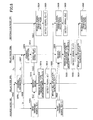
  • FIG. 6 is a flowchart showing a data relay method of an embodiment of the present invention.
  • FIG. 7 is a block diagram of a relay node of an embodiment of the present invention.
  • FIG. 8 is a flowchart showing a data relay method of an embodiment of the present invention.
  • FIG. 9 is a block diagram of a wireless communication system of an embodiment of the present invention.
  • FIG. 10 is a flowchart showing a data relay method of an embodiment of the present invention.
  • FIG. 11 is a block diagram of a destination node of an embodiment of the present invention.
  • FIG. 12 is a flowchart showing a data relay method of an embodiment of the present invention.
  • FIG. 13 is a block diagram of a relay node of an embodiment of the present invention.
  • FIG. 14 is a flowchart showing a data relay method of an embodiment of the present invention.
  • interference canceling stands for canceling a signal from another communication node that is received as interference.
  • Causing interference suppression stands for suppressing an influence to another relay node caused by a signal sent from a relay node.
  • a matrix (interference canceling matrix) used for canceling a signal from another relay node is obtained by obtaining a Moor-Penrose inverse matrix using channel information (backward channel) between a relay node and a source node and channel information (inter-relay node channel) between the relay node and another relay node.
  • a matrix (causing interference suppressing matrix) used for suppressing the influence to another relay node as interference caused by a signal sent from a relay node is obtained by obtaining a Moor-Penrose inverse matrix using channel information (forward channel) between the relay node and the destination node.
  • a relay signal is detected in the destination node by multiplying a receive signal received by the destination node by the Moor-Penrose inverse matrix of the channel information (forward channel) between the destination node and the relay node.
  • interference cancellation is performed in the destination node by subtracting, from the receive signal, a result obtained by multiplying the estimated relay signal by the inter-relay node channel and the backward channel.
  • interference cancellation is performed in the relay node by multiplying the relay receive signal by the Moor-Penrose inverse matrix of a product of the backward channel and the inter-relay node channel.
  • a signal can be detected in the destination node using a sequential type interference canceling method, for example (refer to the non-patent document 3, for example).
  • K a number of usable relay nodes
  • H k k-th channel between source node and relay node (backward channel), 1 ⁇ k ⁇ K
  • G k k-th channel between relay node and receive node (forward channel), 1 ⁇ k ⁇ K
  • A an inter-relay node channel matrix
  • W k a weight matrix in the k-th relay node, 1 ⁇ k ⁇ K
  • n k noise component of the k-th relay node
  • ⁇ r 2 noise power of a relay node (common to all relay nodes)
  • the wireless communication system of this embodiment is described with reference to FIG. 2 .
  • the wireless communication system of the embodiment includes plural communication nodes.
  • the plural communication nodes can be divided to source nodes, relay nodes and destination nodes (receive nodes).
  • a transmit signal sent from the source node is transmitted to a target node via one or more relay node.
  • the wireless communication system of the present embodiment includes a source node 100 , relay nodes 200 1 and 200 2 and a destination node 300 .
  • the number K of the relay nodes is 2, the number of antennas of each of the source node 100 and the destination node 300 is M, the number N 1 of antennas of the relay node 200 1 is 2M, and the number N 2 of antennas of the relay node 200 2 is M.
  • the number K of the relay nodes may be 1 or more than 2.
  • the relay node 200 1 receives a signal (a signal vector may be referred to as a “signal” for the sake of simplicity of explanation) sent from the source node 100 , and at the same time, the relay node 200 2 sends a signal to the destination node 300 .
  • a signal a signal vector may be referred to as a “signal” for the sake of simplicity of explanation
  • the relay node 200 1 sends a signal to the destination node 300 , and at the same time, the relay node 200 2 receives a signal sent from the source node 100 .
  • each time slot at least equal to or more than one relay node of the plural relay nodes receives a transmit signal from the source node, and at least equal to or more than one relay node that is different from the relay node that receives the transmit signal from the source node sends a signal to the destination node in the same time slot.
  • the relay node 200 1 when neither interference cancellation nor causing interference suppression is performed, the relay node 200 1 receives an influence caused by a signal as an interference signal component sent from the relay node 200 2 in the time slot n.
  • the relay node 200 2 receives an influence caused by a signal as an interference signal component sent from the relay node 200 1 .
  • the relay node 200 includes an interference canceling function and a causing interference suppressing function so that the influence of the interference can be reduced.
  • each of the relay nodes 200 1 and 200 2 may include the interference canceling function and the causing interference suppressing function.
  • the relay node 200 is a communication node for relaying a signal between the source node and the destination node.
  • the relay node 200 includes an interference canceling unit 202 that receives a signal sent from the source node 100 , a causing interference suppressing unit 204 that receives an output signal of the interference canceling unit 202 , a weight multiplying unit 206 that receives an output signal of the causing interference suppressing unit 204 and that outputs a transmit signal, and a channel estimation unit 208 that receives a signal sent from the source node 100 .
  • the output signal of the channel estimation unit 208 is supplied to the interference canceling unit 202 and the causing interference suppressing unit 204 .
  • the channel estimation unit 208 estimates channel information (forward channel) between the relay node and the destination node 300 , channel information (backward channel) between the relay node and the source node 100 , and channel information (inter-relay node channel) between the relay node and another relay node. In addition, the channel estimation unit 208 supplies the backward channel and the inter-relay node channel to the interference canceling unit 202 , and supplies the forward channel to the causing interference suppressing unit 204 .
  • the interference canceling unit 202 obtains a matrix (interference canceling matrix B -kM ) for canceling a signal from another node using the supplied backward channel and inter-relay node channel.
  • the interference canceling unit 202 supplies the interference canceling matrix B -kM and a rely receive signal to the causing interference suppressing unit 204 .
  • the causing interference suppressing unit 204 obtains a matrix (causing interference suppressing matrix C k ) using the supplied forward channel for suppressing causing interference such that a signal sent from the own relay node is not received by another relay node as an interference signal.
  • the causing interference suppressing unit 204 supplies the interference canceling matrix B -kM , the causing interference suppressing matrix C k , and the relay receive signal to the weight multiplying unit 206 .
  • the weight multiplying unit 206 multiplies the relay receive signal by the interference canceling matrix obtained by the interference canceling unit 202 and the causing interference suppressing matrix obtained by the causing interference suppressing unit 204 .
  • the source node 100 sends a pilot signal L 1 in step S 402 .
  • the relay node 200 2 sends a pilot signal Z 21 in step S 404 .
  • the channel estimation unit 210 of the relay node 200 1 performs channel estimation based on the pilot signals L 1 and Z 21 received from the source node 100 and the relay node 200 2 respectively in step S 406 .
  • the source node 100 sends a signal s[n] to the relay node 200 1 in step S 408 .
  • the relay node 200 2 sends a signal X 2 [n] including information of s[n ⁇ 1] to the destination node 300 in step S 410 .
  • the relay node 200 1 receives the signal s[n] sent from the source node 100 .
  • the relay node 200 1 receives the signal X 2 [n] sent from the relay node 200 2 in step S 412 . Therefore, a signal y 1 [n] received by the relay node 200 1 in the time slot n is represented as the following equation (5) as a sum of the signal sent from the source node 100 and the signal sent from the relay node 200 2 .
  • y 1 [n] H 1 [n]s[n]+n 1 [n]+A[n]X 2 [n] (5)
  • n 1 [n] stands for a white noise component added in a receive amplifier in the relay node 200 1 .
  • the interference canceling unit 202 of the relay node 200 1 calculates the interference canceling matrix B -kM using the backward channel and the inter-relay node channel in step S 414 .
  • the interference canceling unit 202 of the relay node 200 1 supplies the interference canceling matrix B -kM and the relay receive signal to the causing interference suppressing unit 204 .
  • the causing interference suppressing unit 204 in the relay node 200 1 calculates the causing interference suppressing matrix C k using the forward channel in step S 416 .
  • the causing interference suppressing unit 204 supplies the interference canceling matrix B -kM , causing interference suppressing matrix C k and the relay receive signal to the weight multiplying unit 206 .
  • the weight multiplying unit 206 in the relay node 200 1 generates a relay signal X 1 [n+1] by multiplying the relay receive signal by the supplied interference canceling matrix and causing interference suppressing matrix.
  • the generated relay signal is sent to the destination node 300 in step S 418 .
  • the source node 100 sends s[n+1] to the relay node 200 2 in step S 420 .
  • the weight multiplying unit 206 of the relay node 200 1 multiplies the receive signal y 1 [n] by the interference canceling matrix as shown in the following expression (6) so as to cancel a signal component received from the relay node 200 2 as interference.
  • B[n] (H 1 [n]A[n]), and the number of elements of the matrix is 2M ⁇ 2M.
  • the following expression (7) shows a matrix obtained by performing Moor-Penrose inverse matrix conversion on the matrix B[n], and after that, converting elements from an (M+1)-th low to a 2M-th low to 0.
  • B[n] ⁇ M + (7) As a result, a receive signal after multiplication by the interference canceling matrix is represented as the following equation (8).
  • T indicates transpose of the matrix.
  • the weight multiplying unit 206 of the relay node 200 1 multiplies the receive signal after multiplication by the interference canceling matrix by the causing interference suppressing matrix C[n] as shown in the following expression (9) such that interference is not provided to the relay node 200 2 in generating a transmit signal of the relay node 200 1 .
  • C[n] is represented as the following equation (10)
  • C[n] V[n] H (10)
  • C[n] is defined by a matrix representing a signal part space of the inter-relay node channel A[n+1].
  • C[n] can be obtained by performing singular value decomposition on the inter-relay node channel A[n+1].
  • a ⁇ [ n + 1 ] [ U ⁇ ⁇ [ n ] , U ⁇ [ n ] ] ⁇ [ ⁇ [ n ] 0 0 ] ⁇ [ V ⁇ ⁇ [ n ] H ⁇ V ⁇ [ n ] H ] ( 11 )
  • A[n+1] indicates the inter-relay node channel when the relay node 200 1 sends a signal in the time slot n+1. Instead of A[n+1], A[n] can be used when time variation of the channel is small.
  • a transmit signal X 1 [n+1] in a next time slot in the relay node 200 1 can be represented as the following equation (12).
  • x 1 [n+ 1 ] C[n]B[n] ⁇ M + y 1 [n] (12)
  • the destination node 300 receives the signal X 2 [n] including information of s[n ⁇ 1] sent from the relay node 200 2 in step S 422 .
  • the signal sent from the source node 100 in step S 420 is received by the relay node 200 2 in step S 426 .
  • the receive signal of the relay node 200 2 in the time slot n+1 is represented by the following equation (14).
  • y 2 [n+ 1] H 2 [n+ 1 ]s[n+ 1 ]+n 2 [n+ 1] (14)
  • H 2 [n+1] indicates a matrix representing channel state of the backward channel between the source node 100 and the relay node 200 2 .
  • the relay node 200 2 sends the receive signal y 2 [n+1] as X 2 [n+ 2 ] in step S 428 .
  • step S 430 the destination node 300 receives the relay signal X 1 [n+1] sent from the relay node 200 1 in step S 418 .
  • step S 434 the destination node 300 receives the relay signal sent from the relay node 200 2 in step S 428 .
  • the destination node 300 detects s[n+1] from the receive signal in step S 436 .
  • the receive signals in the destination node 300 that are sent from the source node 100 in time slots n and n+1 are represented as the equations (15) and (16) respectively.
  • r[n+ 1 ] G 1 [n+ 1 ]X 1 [n+ 1 ]+z[n+ 1]
  • r[n+ 2 ] G 2 [n+ 2 ]X 2 [n+ 2 ]+z[n+ 2] (16)
  • z indicates a noise component added in the receive amplifier in the destination node 300 .
  • signals s[n] and s[n+1] are detected from the equations (15) and (16).
  • the interference canceling (reducing) function canceling influence of the signal from the relay node 200 2 and the causing interference canceling function for canceling interference provided to the relay node 200 2 receiving by the relay node 200 1 and sending by the relay node 200 2 can be performed simultaneously.
  • the number of the antennas of a relay node that does not include the interference canceling function and the causing interference suppressing function is M and that the number of antennas of the source node 100 is M
  • the relay node having the interference canceling function and the causing interference suppressing function performs zero-forcing type signal processing for realizing the interference canceling function and the causing interference suppressing function
  • the number of the antennas is equal to or greater than M ⁇ (number of relay nodes that does not have the interference canceling function and the causing interference suppressing function).
  • the relay node 200 sends a received signal as it is.
  • a part of relay nodes perform receiving processes, and at the same time, other relay nodes perform sending processes.
  • the configuration of the wireless communication system of this embodiment is the same as that of the wireless communication system described with reference to FIG. 2 .
  • the destination node 300 is a communication node that receives a signal sent from the source node via the relay node.
  • the destination node 300 includes a transmit signal estimation unit 302 that receives a signal sent from the relay node 200 , an estimated signal storing unit 304 that receives an output signal of the transmit signal estimation unit 302 , an interference canceling unit 306 that receives an output signal of the estimated signal storing unit 304 , and a source node signal detection unit 308 that receives an output signal from the interference canceling unit 306 , and a channel estimation unit 310 that receives the signal sent from the relay node 200 .
  • An output signal of the channel estimation unit 310 is supplied to the transmit signal estimation unit 302 , the interference canceling unit 306 and the source node signal detection unit 308 .
  • the transmit signal estimation unit 302 estimates the signal from the relay node 200 using the forward channel, and supplies the estimated signal to the estimated signal storing unit 304 .
  • the estimated signal storing unit 304 stores the signal estimated by the transmit signal estimation unit 302 .
  • the interference canceling unit 306 cancels interference using the signal stored in the estimated signal storing unit 304 and channel information obtained by multiplying the inter-node channel by the backward channel. For example, the interference canceling unit 306 cancels interference in a current time slot using the signal stored in the estimated signal storing unit 304 in a previous time slot.
  • the source node signal detection unit 308 detects a signal from the source node 100 .
  • the channel estimation unit 310 estimates channel information that is a product of the forward channel, the inter-relay node channel and the backward channel. For example, the channel estimation unit 310 estimates channel information obtained by multiplying the inter-relay node channel by the channel between the destination node and the relay node, and estimates channel information between the destination node and the relay node.
  • the relay node 200 after the relay node 200 adjusts power of a received signal, the relay node 200 sends the signal to the destination node 300 without performing either interference canceling or causing interference suppression.
  • the source node 100 sends a transmit signal s[n] to the relay node 200 1 in step S 602 .
  • the relay node 200 2 sends a relay signal X 2 [n] to the destination node 300 in step S 604 .
  • the relay node 200 1 receives a transmit signal s[n] and a relay signal X 2 [n] in step S 606 .
  • the receive signal of the relay node 200 1 is represented as the following equation (17).
  • y 1 [n] H 1 [n]s[n]+n 1 [n]+A[n]X 2 [n] (17)
  • the source node 100 sends a transmit signal s[n+1] to the relay node 200 2 in step S 610 .
  • step S 612 the destination node 300 receives the relay signal sent from the relay node 200 2 in step S 604 .
  • This receive signal is represented as the following equation (18).
  • r[n] G 2 [n]X 2 [n]+z[n] (18)
  • the transmit signal estimation unit 302 of the destination node 300 detects the relay signal X 2 [n] from the receive signal r[n] and stores the detected signal in the estimated signal storing unit 304 in step S 613 .
  • the destination node 300 cancels interference occurring between relay nodes using the receive signal in the previous time slot in step S 614 .
  • the receive signal in the previous time slot n is represented as the following equation (19).
  • r[n ⁇ 1 ] G 1 [n ⁇ 1 ]X 1 [n ⁇ 1 ]+z[n ⁇ 1] (19)
  • X 1 [n ⁇ 1] is estimated using channel information G 1 [n ⁇ 1].
  • the interference occurring between relay nodes included in the receive signal in the time slot n can be canceled using the estimated value. More particularly, the interference signal component X 1 [n ⁇ 1] is canceled from the receive signal.
  • step S 616 the transmit signal s[n ⁇ 1] from the source node 100 is detected in step S 616 .
  • step S 618 the relay signal X 1 [n+1] sent in step S 608 is received by the destination node 300 in a time slot n+1.
  • the receive signal is represented by the following equation (20).
  • the transmit signal estimation unit 302 of the destination node 300 detects the relay signal X 1 [n+1] from the receive signal r[n+1] and stores the detected signal in the estimated signal storing unit 304 in step S 619 .
  • the destination node 300 cancels interference occurring between the relay nodes using the receive signal in the previous time slot in step S 620 .
  • the receive signal in a previous time slot n is represented as the following equation (21).
  • r[n] G 1 [n]X 2 [n]+z[n] (21)
  • X 2 [n] is estimated using channel information G 1 [n].
  • the estimated value of X 2 [n] can be represented as the following equation (22).
  • step S 622 the destination node 300 detects the transmit signal s[n] from the source node 100 using the equation (23).
  • n err is a difference between a real value of X 2 [n] and the estimated value.
  • step S 624 the relay node 200 2 receives s[n+1] sent in step S 610 and X 1 [n+1] sent in step S 608 .
  • the receive signal received by the relay node 200 2 is represented as the equation (24).
  • y 2 [n+ 1 ] H 2 [n+ 1 ]s[n+ 1 ]+n 2 [n+ 1 ]+A[n+ 1 ]X 1 [n+ 1] (24)
  • the transmit signal X 2 [n+2] is also received by the relay node 200 1 .
  • signal transmission by the relay node 200 1 and signal receiving by the relay node 200 2 can be performed simultaneously.
  • each relay node performs signal detection so as to cancel interference between relay nodes. Accordingly, the signal from which interference is canceled in the relay nodes can be sent without performing causing interference suppression. In addition, it is not necessary that the destination node 300 performs interference cancellation between relay nodes.
  • the configuration of the wireless communication system of this embodiment is the same as that shown in FIG. 2 .
  • the relay node 200 is a communication node for relaying a signal between the source node and the destination node.
  • the relay node 200 includes an interference canceling unit 202 that receives a receive signal, a signal detection unit 210 that receives an output signal of the interference canceling unit 202 , a weight multiplying unit 206 that receives an output signal of the signal detection unit 210 , and a channel estimation unit 208 that receives the receive signal.
  • An output signal of the channel estimation unit 208 is supplied to the interference canceling unit 202 and the signal detection unit 210 .
  • the interference canceling unit 202 cancels a signal from another node when receiving a signal from the source node using channel information (backward channel) between the source node 100 and the relay node 200 and channel information (inter-relay node channel) between the own relay node and another relay node. In addition, the interference canceling unit 202 supplies the receive signal from which interference is canceled to the signal detection unit 210 .
  • the weight multiplying unit 206 multiplies an output of the signal detection unit 210 by a weight to generate a transmit signal.
  • the channel estimation unit 208 estimates channel information of the backward channel and the inter-relay node channel.
  • non-regenerative relay is described in the first and second embodiments
  • regenerative relay is described in this embodiment.
  • the source node 100 sends a pilot signal L 1 in step S 802 .
  • the relay node 200 2 sends a pilot signal Z 21 in step S 804 .
  • the channel estimation unit 210 of the relay node 200 1 performs channel estimation based on the pilot signals L 1 and Z 21 sent from the source node 100 and the relay node 200 2 respectively in step S 806 .
  • the relay node 200 1 sends a pilot signal Z 12 in step S 807 .
  • the relay node 200 1 may send the pilot signal Z 12 before performing the channel estimation in step S 806 .
  • the source node 100 sends a pilot signal L 2 in step S 808 .
  • the pilot signal L 2 may be the same as the pilot signal L 1 .
  • the channel estimation unit 210 of the relay node 200 2 performs channel estimation based on the pilot signals L 2 and Z 12 sent from the source node 100 and the relay node 200 1 respectively in step S 809 .
  • the source node 100 sends a signal s[n] to the relay node 200 1 in step S 810 .
  • the relay node 200 2 sends a signal X 2 [n] including information of s[n ⁇ 1] to the destination node 300 in step S 812 .
  • the relay node 200 1 receives the signal s[n] sent from the source node 100 .
  • the relay node 200 1 receives the signal X 2 [n] sent from the relay node 200 2 in step S 814 . Therefore, a signal y 1 [n] received by the relay node 200 1 in the time slot n is obtained by summing the signal sent from the source node 100 and the signal sent from the relay node 200 2 and is represented as the following equation (25).
  • y 1 [n] H 1 [n]s[n]+n 1 [n]+A[n]X 2 [n] (25)
  • n 1 [n] is a white nose component added in the receiving amplifier in the relay node 200 1 .
  • the interference canceling unit 202 of the relay node 200 1 cancels a signal from another node using the backward channel and the inter-relay node channel.
  • the interference canceling unit 202 supplies the relay receive signal after interference is canceled to the signal detection unit 210 in step 816 .
  • the signal detection unit 210 detects the signal s[n] sent from the source node 100 by performing signal decision using the signal from which interference is canceled in step S 818 .
  • the weight multiplying unit 206 multiplies an output of the signal detection unit 210 by a weight to generate a transmit signal X 1 [n+1].
  • the generated relay signal is sent to the destination node 300 in step S 820 .
  • the source node 100 sends s[n+1] to the relay node 200 2 in step S 822 .
  • the transmit signal X 2 [n] from the relay node 200 2 in the time slot n can be represented as the following equation (26).
  • x 2 [n] w 2 [n ⁇ 1 ] ⁇ tilde over (s) ⁇ [n ⁇ 1] (26)
  • w 2 [n] is a transmit weight of the relay node 200 2 .
  • the expression (27) indicates a decision value of s[n ⁇ 1].
  • ⁇ tilde over (s) ⁇ [n ⁇ 1] (27) Transmit weights w 1 and w 2 of the relay nodes 200 1 and 200 2 can be represented as follows.
  • s[n] can be detected using the sequential type interference canceling method and the like for the equation (26).
  • the relay node 200 1 multiplies the detected s[n] by a weight matrix w 1 [n] so as to generate a transmit signal X 1 [n+1].
  • w 1 [n] w 1 [n] ⁇ tilde over (s) ⁇ [n]
  • step S 824 the destination node 300 receives the signal X 2 [n] including information of s[n ⁇ 1] sent from the relay node 200 2 in step S 812 .
  • the destination node 300 detects S[n ⁇ 1] from the receive signal in step S 826 .
  • the relay node 200 2 receives a signal s[n+1] sent from the source node 100 .
  • the relay node 200 2 receives the signal X 1 [n+1] sent from the relay node 200 1 in step S 828 . Therefore, a signal y 2 [n+1] received by the relay node 200 2 in the time slot n+1 is obtained by summing the signal sent from the source node 100 and the signal sent from the relay node 200 1 and is represented as the following equation (32).
  • n 2 [n+1] is a white nose component added in the receiving amplifier in the relay node 200 2 .
  • the interference canceling unit 202 of the relay node 200 2 cancels a signal from another node using the backward channel and the inter-relay node channel.
  • the interference canceling unit 202 supplies the relay receive signal after interference is canceled to the signal detection unit 210 in step 830 .
  • the signal detection unit 210 detects the signal s[n+1] sent from the source node 100 by performing signal decision using the signal from which interference is canceled in step S 832 .
  • the weight multiplying unit 206 multiplies an output of the signal detection unit 210 by a weight to generate a transmit signal X 2 [n+1].
  • the generated relay signal is sent to the destination node 300 in step S 834 .
  • the source node 100 sends s[n+2] to the relay node 200 2 .
  • step S 836 the destination node 300 receives the relay signal X 1 [n+1] sent from the relay node 200 1 .
  • the destination node 300 detects S[n] from the receive signal in step S 838 .
  • the destination node 300 receives the relay signal sent from the relay node 200 2 in step S 840 . After that, similar processes are performed.
  • the relay node including the interference canceling function the more the number of the antennas is, the better. For example, assuming that the number of the antennas of each of the source node and the destination node is M, when the relay node performs zero-forcing type signal processing for realizing the interference canceling function, it is necessary that the number of the antennas is equal to or greater than twice as that of the antennas of the source node.
  • the wireless communication system of this embodiment is divided into two relay groups 1 and 2 , wherein each group includes more than one relay node.
  • Each relay node sends a received signal as it is or after amplifying it.
  • one relay group performs receiving processes at the same time when another relay group performs transmission processes.
  • a ij a channel matrix between an i-th relay node of the relay group 1 and a j-th relay node of the relay group 2
  • n ij noise component of the j-th relay node of the i-th relay group
  • ⁇ r 2 noise power of a relay node (common to all relay nodes)
  • the wireless communication system of this embodiment is described with reference to FIG. 9 .
  • the wireless communication system of this embodiment includes plural communication nodes that are divided into a source node 100 , relay nodes and a destination node (receive node) 300 .
  • a transmit signal sent from the source node 100 is transmitted to the destination node 300 via one or more relay nodes.
  • the wireless communication system of this embodiment includes a source node 100 , a relay group 1 including plural relay nodes (more than one), a relay group 2 including plural relay nodes (more than one), and a destination node 300 .
  • each of the numbers K and L of the relay nodes in the relay groups may be more than two.
  • the number of antennas of the destination node 300 is MAX (K,L) ⁇ N, wherein MAX (K,L) is a function that returns a larger value between K and L.
  • the number of the relay nodes may be different between the two relay groups.
  • the relay nodes 11 and 12 belonging to the relay group 1 receives a signal sent from the source node 100 , and at the same time, the relay nodes 21 and 22 belonging to the relay group 2 sends a signal to the destination node 300 .
  • the relay nodes 11 and 12 belonging to the relay group 1 sends a signal to the destination node 300 , and at the same time, the relay nodes 21 and 22 belonging to the relay group 2 receives a signal sent from the source node 100 .
  • each time slot at least equal to or more than two of the plural relay nodes belonging to one relay group receive a transmit signal from the source node 100 , and at least equal to or more than two of the plural relay nodes belonging to another relay group sends a signal to the destination node 300 in the same time slot.
  • the relay nodes 11 and 12 belonging to the relay group 1 receives an influence of the signal sent from the relay nodes 21 and 22 belonging to the relay group 2 as an interference signal component.
  • the relay nodes 21 and 22 belonging to the relay group 2 receives an influence of the signal sent from the relay nodes 11 and 12 belonging to the relay group 1 as an interference signal component.
  • the destination node 300 of this embodiment has the same configuration as one shown in FIG. 5 , and includes a transmit signal estimation unit 302 that receives a signal sent from the relay nodes ( 11 , 12 ) belonging to the relay group 1 or the relay nodes ( 21 , 22 ) belonging to the relay group 2 , an estimated signal storing unit 304 that receives an output signal of the transmit signal estimation unit 302 , an interference canceling unit 306 that receives an output signal of the estimated signal storing unit 304 , a source node signal detection unit 308 that receives an output signal from the interference canceling unit 306 , and a channel estimation unit 310 that receives the signal sent from the relay node.
  • An output signal of the channel estimation unit 310 is supplied to the transmit signal estimation unit 302 , the interference canceling unit 306 and the source node signal detection unit 308 .
  • the transmit signal estimation unit 302 estimates the signal from each relay node ( 11 , 12 , 21 , 22 ) using the forward channel between the destination node 300 and the relay node, and supplies the estimated signal to the estimated signal storing unit 304 .
  • the estimated signal storing unit 304 stores the signal estimated by the transmit signal estimation unit 302 .
  • the interference canceling unit 306 realizes interference cancellation using products of the signals stored in the estimated signal storing unit 304 for each relay node, channels between each relay node and relay nodes of another relay group, and channels between the relay nodes and the destination node by subtracting, from the receive signal, a sum (estimated value) of signals obtained by multiplying the signals stored in the estimated signal storing unit 304 for each node by the combined channels.
  • the source node signal detection unit 308 detects a signal from the source node 100 using the signal from which interference is canceled from the receive signal by the interference removing unit 306 .
  • the channel estimation unit 310 estimates forward channels for each relay node, and products of channels between each relay node and each relay node of another relay group and channels between relay nodes of another relay group and the destination node. For example, the channel estimation unit 310 estimates, as estimation of combined channel information on the relay node 11 , a product of a channel between the relay node 11 and the relay node 21 and a forward channel between the relay node 21 and the destination node, and estimates a product of a channel between the relay node 11 and the relay node 22 and a forward channel between the relay node 22 and the destination node.
  • the relay node after the relay node ( 11 , 12 , 21 , 22 ) adjusts power of a received signal, the relay node sends the signal to the destination node 300 .
  • the source node sends a transmit signal s[n] to the relay nodes 11 and 12 belonging to the relay group 1 .
  • the relay nodes 21 and 22 send relay signals X 21 [n], X 22 [n] to the destination node respectively.
  • Each of the relay nodes 11 and 12 receives a transmit signal s[n] and relay signals X 21 [n] and X 22 [n] from the relay group 2 .
  • the receive signal of the relay node 11 is represented as the following equation (34).
  • the receive signals at the destination node in the time slots n, n+1 and n+2 are represented as the following equations (36), (37) and (38) respectively.
  • the transmit signal estimation unit 302 of the destination node 300 estimates the relay signals X 21 [n] and X 22 [n] from the receive signal r[n] and stores the estimated signals in the estimated signal storing unit 304 .
  • the relay signals X 21 [n] and X 22 [n] can be estimated using the Moore-Penrose inverse matrix of the forward channels of the relay group 2 as shown in the equation (39).
  • the destination node 300 cancels interference occurring between relay nodes using the receive signals in the previous time slot.
  • interference occurring between relay nodes included in the receive signal in the time slot n+1 can be canceled using X 21 [n] and X 22 [n] estimated from the equation (39) for the equation (37). More particularly, the interference signal components X 21 [n] and X 22 [n] are canceled from the receive signal as follows.
  • each group includes more than one relay node.
  • Each relay node sends a received signal as it is or after amplifying it.
  • one relay group performs receiving processes at the same time when another relay group performs transmission process.
  • a ij channel matrix between an i-th relay node of the relay group 1 and a j-th relay node of the relay group 2
  • n ij noise component of the j-th relay node of the i-th relay group
  • ⁇ r 2 noise power of a relay node (common to all relay nodes)
  • the wireless communication system of this embodiment is described with reference to FIG. 9 .
  • the wireless communication system of this embodiment includes plural communication nodes that are divided into a source node (source node) 100 , relay nodes and a destination node (receive node) 300 .
  • a transmit signal sent from the source node 100 is transmitted to the destination node 300 via one or more relay node.
  • the wireless communication system of this embodiment includes a source node 100 , a relay group 1 including plural relay nodes (more than one), a relay group 2 including plural relay nodes (more than one), and a destination node 300 .
  • each of the numbers K and L of the relay nodes in the relay groups may be more than two.
  • the relay nodes 11 and 12 belonging to the relay group 1 receives a signal sent from the source node 100 , and at the same time, the relay nodes 21 and 22 belonging to the relay group 2 sends a signal to the destination node 300 .
  • the relay nodes 11 and 12 belonging to the relay group 1 sends a signal to the destination node 300 , and at the same time, the relay nodes 21 and 22 belonging to the relay group 2 receives a signal sent from the source node 100 .
  • each time slot at least equal to or more than two of the plural relay nodes belonging to one relay group receives a transmit signal from the source node 100 , and at least equal to or more than two of the plural relay nodes belonging to another relay group sends a signal to the destination node 300 at the same time slot.
  • the relay nodes 11 and 12 belonging to the relay group 1 receives an influence of a signal sent from the relay nodes 21 and 22 belonging to the relay group 2 as an interference signal component.
  • the relay nodes 21 and 22 belonging to the relay group 2 receives an influence of a signal sent from the relay nodes 11 and 12 belonging to the relay group 1 as an interference signal component.
  • the destination node includes a channel estimation unit 318 that receives a signal sent from a relay node, a source node signal detection unit 312 that receives an output of the channel estimation unit 318 and a signal sent from the relay node, an estimated signal storing unit 314 that receives an output signal from the source node signal detection unit 312 , and an interference canceling unit 316 that receives an output of the estimated signal storing unit 314 and an output of the channel estimation unit 318 .
  • the output signal of the interference canceling unit 316 is supplied to the source node signal detection unit 312 .
  • the source node signal detection unit 312 detects a signal sent from the source node 100 using the signal sent from each relay node ( 11 , 12 , 21 , 22 ) using the forward channel of each relay node, and supplies the detected signal into the estimated signal storing unit 314 .
  • the estimated signal storing unit 314 stores the signal estimated by the source node signal detection unit 312 .
  • the interference canceling unit estimates a signal that causes interference using the estimated source node transmit signal estimated by the source node signal detection unit 312 and channel information obtained by multiplying the inter-relay node channel by the forward channel, and supplies the signal to the source node signal detection unit 312 .
  • the interference canceling unit 316 realizes interference cancellation by canceling a sum of all relay signals (estimated value) that cause interference from the receive signal.
  • the source node signal detection unit 312 detects the signal from the source node using the signal from which interference is canceled.
  • the channel estimation unit 318 estimates a product of channels between all relay nodes in the relay node 1 and each relay node in the relay group 2 and channels between the destination node and each relay nodes in the relay group 2 , a product of channels between the source node 100 and all relay nodes in the relay group 2 , channels between all relay nodes in the relay group 2 and each relay node in the relay group 1 , and channels between the destination node and all relay nodes in the relay group 1 , and a product of channels between the source node 100 and each relay node and channels between the destination node and each relay node, and a product of channels between the source node 100 and each relay node and channels between the destination node and each relay node.
  • the channel estimation unit 318 estimates a product of a sum of a channel between the relay node 11 and the relay node 21 and a channel between the relay node 11 and the relay node 22 , and the forward channel between the relay node 11 and the destination node, and estimates a product of a channel between the relay node 11 and the source node and the forward channel between the relay node 11 and the destination node.
  • each of the relay nodes 11 , 12 , 21 and 22 sends a received signal to the destination node 300 after adjusting the power of the received signal.
  • the source node 100 sends a transmit signal s[n] to the relay nodes 11 and 12 belonging to the relay group 1 .
  • the relay nodes 21 and 22 belonging to the relay group 2 sends relay signals X 21 [n] and X 22 [n] to the destination node 300 .
  • the relay nodes 11 and 12 belonging to the relay group 1 receive the transmit signal s[n] and the relay signals X 21 [n] and X 22 [n].
  • a receive signal of the relay node 11 is represented as the following equation (41).
  • a receive signal of the relay node 12 is represented as the following equation (42).
  • Receive signals received by the destination node 300 in time slots n, n+1, and n+2 are represented as the following equations (43), (44) and (45) respectively.
  • the destination node 300 cancels interference occurring between relay nodes using the stored estimated source node transmit signal in the previous slot.
  • the interference occurring between relay nodes included in the receive signal in the time slot n+1 can be canceled using the s[n ⁇ 1] estimated from the equation (43) for the equation (44). More particularly, the interference signal component is canceled from the receive signal as shown in the following equation (46).
  • each group includes more than one relay node.
  • Each relay node sends a received signal as it is or after amplifying it.
  • one relay group performs receiving processes at the same time when another relay group performs sending processes.
  • a ij channel matrix between an i-th relay node of the relay group 1 and a j-th relay node of the relay group 2
  • n ij noise component of the j-th relay node of the i-th relay group
  • ⁇ r 2 noise power of a relay node (common to all relay nodes)
  • the wireless communication system of this embodiment is described with reference to FIG. 9 .
  • the wireless communication system of this embodiment includes plural communication nodes that are divided into a source node (source node) 100 , relay nodes and a destination node (receive node) 300 .
  • a transmit signal sent from the source node 100 is transmitted to the destination node 300 via one or more relay nodes.
  • the wireless communication system of this embodiment includes a source node 100 , a relay group 1 including plural relay nodes (more than one), a relay group 2 including plural relay nodes (more than one), and a destination node 300 .
  • each of the numbers K and L of the relay nodes in the relay groups may be more than two.
  • the relay nodes 11 and 12 belonging to the relay group 1 receives a signal sent from the source node 100 , and at the same time, the relay nodes 21 and 22 belonging to the relay group 2 sends a signal to the destination node 300 .
  • the relay nodes 11 and 12 belonging to the relay group 1 sends a signal to the destination node 300 , and at the same time, the relay nodes 21 and 22 belonging to the relay group 2 receives a signal sent from the source node 100 .
  • each time slot at least equal to or more than two of the plural relay nodes belonging to one relay group receives a transmit signal from the source node 100 , and at least equal to or more than two of the plural relay nodes belonging to another relay group sends a signal to the destination node 300 at the same time slot.
  • the relay nodes 11 and 12 belonging to the relay group 1 receives an influence of a signal sent from the relay nodes 21 and 22 belonging to the relay group 2 as an interference signal component.
  • the relay nodes 21 and 22 belonging to the relay group 2 receives an influence of a signal sent from the relay nodes 11 and 12 belonging to the relay group 1 as an interference signal component.
  • the relay node includes a channel estimation unit 218 for estimating a channel between the source node 100 and the relay node and channels between the relay node and relay nodes of the different relay group, an interference canceling unit 210 for performing interference cancellation on a signal from the source node 100 , a source node signal detection unit (source signal detection unit) 212 for receiving an output signal of the interference canceling unit 210 and detecting the source node signal, a transmit power control unit 214 that receives an output signal of the source node signal detection unit 212 , and a weight calculation unit 216 that receives an output signal of the channel estimation unit 218 .
  • An output signal of the weight calculation unit 216 is supplied to the interference canceling unit, the source node signal detection unit 212 , and the transmit power control unit 214 .
  • the relay node belongs to the relay group 1 or the relay group 2 .
  • the channel estimation unit 218 of the relay node estimates channel information between the own relay node and the source node and estimates channel information between the own relay node and all relay nodes belonging to the relay group 2 when the own relay node belongs to the relay group 1
  • the channel estimation unit 218 of the relay node estimates channel information between the own relay node and the source node and estimates channel information between the own relay node and all relay nodes belonging to the relay group 1 when the relay node belongs to the relay group 2 .
  • the interference canceling unit 210 cancels an interference signal from other relay nodes based on the channel information estimated by the channel estimation unit 218 .
  • the source node signal detection unit 212 detects a signal sent from the source node from the signal from which the interference signal is canceled.
  • each of the relay nodes 11 , 12 , 21 and 22 restores the source node transmit signal from a received signal, and sends the restored signal to the destination node.
  • the source node 100 sends a transmit signal s[n] to the relay nodes 11 and 12 .
  • the relay nodes 21 and 22 sends relay signals X 21 [n] and X 22 [n] respectively after adjusting the power to the destination node 300 .
  • the signals are represented as follows.
  • X 21 [n] E 21 [n] ( s[n ⁇ 1 ],s[n ⁇ 1]) H (47)
  • X 22 [n] E 22 [n] ( s[n ⁇ 1 ],s[n ⁇ 1]) H (48) That is, the relay node that has N antennas that is more than twice the number M of antennas of the source node 100 copies the estimated source node transmit signal s[n ⁇ 1] that was sent by the M antennas so as to send the relay signal using the N antennas, wherein the estimated source node transmit signal s[n ⁇ 1] is stored in the previous time slot.
  • Each of the relay nodes 11 and 12 receives the transmit signal s[n] and the relay signals X 21 [n] and X 22 [n] of the relay group 2 .
  • the receive signal of the relay node 11 is represented by the following equation (49).
  • the equation (49) can be represented as follows from the equations (47) and (48)
  • B 11 indicates a channel matrix of N ⁇ M
  • an i-th (1 ⁇ i ⁇ M) column is a sum of an i-th column and an (i+M) ⁇ the column of A 12 (N ⁇ N).
  • the interference component can be deleted by multiplying the receive signal (51) by the expression (53).
  • the receive signal received by the destination node 300 in the time slot n can be represented as the equation (54).
  • the destination node 300 detects a transmit signal s[n ⁇ 1] sent from the source node 100 using the receive signal shown as the equation (54).
  • the communication node, the wireless communication system and the data relay method of the present invention can be applied to wireless communication systems.
  • a communication node for receiving a signal sent from a source node via a relay node includes an interference canceling unit configured to cancel an interference signal caused between the relay nodes.
  • the communication node receives the signal sent from the source node via plural relay nodes, and the plural relay nodes are divided into a first relay group including more than one relay node and a second relay group including more than one relay node, and the communication node further includes: a channel estimation unit configured to estimate channel information between the communication node and relay nodes in the first relay group, channel information between the communication node and relay nodes in the second relay group, channel information obtained by multiplying channels between the source node and each relay node by channels between the communication node and each relay node, channel information obtained by multiplying channels between each relay node in the first relay group and each relay node in the second relay group by channels between the communication node and each relay node in the second relay group, and channel information obtained by multiplying channels between each relay node in the first relay group and each relay node in the second relay group by channels
  • the may include: a channel estimation unit configured to estimate channel information that is a product of channels between the source node and relay nodes in the first relay group, channels between relay nodes in the first relay group and each relay node in the second relay group, and channels between the communication node and each relay node in the second relay group, estimate channel information that is a product of channels between the source node and relay nodes in the second relay group, channels between relay nodes in the second relay group and each relay node in the first relay group, and channels between the communication node and each relay node in the first relay group, and estimate channel information that is a product of channels between the source node and each relay node and channels between the communication node and each relay node; a transmit detection unit configured to detect a transmit signal from the source node based on the channel information estimated by the channel estimation unit; and a storing unit configured to store the transmit signal detected by the transmit signal detection unit, wherein the interference canceling unit cancels the interference signal based on the signal stored in the storing unit and the
  • a communication node for relaying a signal between a source node and a destination node includes: a relay signal generation unit configured to generate a transmit signal by reducing, from a receive signal, an interference signal from another communication node and performing a process such that the transmit signal is not received as an interference signal by another communication node.
  • the communication node is one of plural relay nodes for relaying a signal between the source node and the destination node, and the plural relay nodes are divided into a first relay group including more than one relay node and a second relay group including more than one relay node, and the communication node belongs to the first relay group or the second relay group, and the communication node may further includes: a channel estimation unit configured to estimate channel information between the communication node and the source node and channel information between the communication node and relay nodes in the second relay group when the communication node belongs to the first relay group, and estimate channel information between the communication node and the source node and channel information between the communication node and relay nodes in the first relay group when the communication node belongs to the second relay group; an interference canceling unit configured to cancel an interference signal from another relay node based on channel the information estimated by the channel estimation unit, and wherein the relay signal generation unit detects the signal sent from the source node from the signal from which the interference signal is canceled.
  • a channel estimation unit configured to estimate channel information between the

Abstract

A communication node for relaying a signal between a source node and a destination node is disclosed. The communication node includes: a relay signal generation unit configured to generate a transmit signal by reducing, from a receive signal, an interference signal from another communication node and performing a process such that the transmit signal is not received as an interference signal by another communication node.

Description

BACKGROUND OF THE INVENTION
1. Field of the Invention
The present invention generally relates to a wireless communication technical field. More particularly, the present invention relates to a communication node, a wireless communicant system and a data relay method that use the multi-hop scheme, the relay scheme and the MIMO (Multi-Input Multi-Output) scheme.
2. Description of the Related Art
In a conventional relay method, signal transmission and signal receiving are performed in a time division manner such that a transmit signal and a receive signal does not interfere with each other at the relay node. However, communication capacity is largely reduced due to the time division scheme so that the communication capacity of the relay system is limited.
The conventional relay method is described with reference to FIG. 1. The reason why the communication capacity is largely limited is described in the following.
In FIG. 1, following parameters are defined.
s: a transmit signal vector sent from a source node
r: a receive signal vector
K: a number of usable relay nodes
Hk: a k-th channel between source node and relay node (backward channel), 1≦k≦K
Gk: a k-th channel between relay node and receive node (forward channel), 1≦k≦K
Wk: weight matrix in the k-th relay node, 1≦k≦K
Ek: power limit coefficient in the k-th relay node 1≦k≦K (for limiting maximum power in each relay node)
nk: noise component in the k-th relay node
z: noise component of receive node
E(·): ensemble mean value of variable
As shown in FIG. 1, a receive signal that is sent from a source node 1 using plural antennas and that is received by each relay node 2 can be represented as an equation (1).
y k =H k s+n k  (1)
The relay node 2 multiplies this signal by the power limit coefficient Ek and the weight matrix Wk to produce a relay transmit signal as shown in the following equation (2).
X k =E k W k y k  (2)
As a result, a receive signal at a destination node 3 can be represented as the following equation (3).
r = k = 1 K G k x k + z ( 3 )
When transmission and receiving are performed simultaneously in each relay node, a signal sent from a relay node is received by another relay node so that interference occurs. As a result, the relay node cannot properly receive a signal sent from the source node 1.
Therefore, in the conventional relay method, as shown in FIG. 1, a time slot in which the source node 1 sends a signal and the relay node receives the signal and a time slot in which the relay node sends a signal and the destination node 3 receives the signal are separately provided. Thus, two time sols are necessary for information sent from the source node 1 to arrive at the destination node 3. Communication capacity of this case is represented as the following equation (4).
C upper =E (Hk,Gk){(½)I(s;y 1 . . . ,y K , r|X 1 , . . . , X K)}  (4)
The term of “½” in the equation (4) is caused by the fact that the two time slots are used. Therefore, the communication capacity is limited as a whole.
By the way, there are following documents relating to the technical field of the present invention.
Non patent document 1: Rohit U. Nabar, et al., “Capacity Scaling Laws in MIMO Wireless networks”, Allerton Conference on Communication, Control, and Computing, Monticello, Ill. pp. 378-389, October 2003.
Non patent document 2: Hui Shi, et al., “A Relaying Scheme using QR Decomposion with Phase Control for MIMO Wireless Networks,” IEEE International Conference on Communications, Volume 4, 16-20 May 2005 Page(s): 2705-2711.
Non patent document 3: G. D. Golden, G. J. Foschini, R. A. Valenzuela, and P. W. Wolniansky, “Detection Algorithm and Initial Laboratory Results using the V-Blast Space-Time Communication Architecture”, Electronic Letters, Vol. 35, No. 1, Jan. 7, 1999.
The above-mentioned conventional technique has a following problem.
As mentioned above, in the conventional relay system, the time slot in which the source node 1 sends a signal and the relay node receives the signal, and the time slot in which the relay node sends a signal and the destination node 3 receives the signal are separately used. By separately providing the time for the relay node to send a signal and the time for the relay node to receive a signal, interference among plural antennas in a relay node and interference among relay nodes can be avoided. However, as represented by the multiplication of “½” in the equation (4) representing the communication capacity, there is a problem in that the communication capacity is reduced.
SUMMARY OF THE INVENTION
An object of the present invention is to provide a relay node, a destination node and a communication method for improving the communication capacity in the multi-hop scheme or the relay scheme using the MIMO scheme.
The object can be achieved by a communication node for relaying a signal between a source node and a destination node, including:
a relay signal generation unit configured to generate a transmit signal by reducing, from a receive signal, an interference signal from another communication node and performing a process such that the transmit signal is not received as an interference signal by another communication node.
The present invention can be also configured as a communication node for receiving a signal sent from a source node via a relay node, including:
an interference canceling unit configured to cancel an interference signal caused between the relay nodes.
The present invention can be also configured as a wireless communication system including a communication node for relaying a signal between a source node and a destination node, the communication node including:
a relay signal generation unit configured to generate a transmit signal by reducing, from a receive signal, an interference signal from another communication node and performing a process such that the transmit signal is not received as an interference signal by another communication node.
In addition, the present invention can be configured as a wireless communication system including a communication node for receiving a signal sent from a source node via a relay node, and the communication node including:
an interference canceling unit for canceling an interference signal between the relay nodes.
Further, the present invention can be configured as a data relay method in a wireless communication system including a relay node for relaying a signal between a source node and a destination node, the method including:
a channel estimation step of estimating channel information between the relay node and the source node, channel information between the relay node and another relay node, and channel information between the relay node and the destination node;
an interference canceling matrix calculation step of obtaining an interference canceling matrix for canceling an interference signal from another relay node based on the channel information between the relay node and the source node and the channel information between the relay node and another relay node; and
a causing interference suppressing matrix calculation step of obtaining a causing interference suppressing matrix for suppressing interference to be caused by a transmitted signal sent by the relay node in another relay node based on the channel information between the relay node and the destination node;
a relay signal generation step of generating a relay signal by multiplying a receive signal by the interference canceling matrix and the causing interference suppressing matrix; and
a relay signal sending step of sending the relay signal.
In addition, the present invention can be configured as a data relay method in a wireless communication system including a destination node for receiving a signal sent from a source node via a relay node, including:
a channel estimation step of estimating channel information which is a product of a channel between relay nodes and a channel between the destination node and the relay node, and estimating channel information between the destination node and the relay node;
a transmit signal estimation step of estimating a transmit signal based on the channel information estimated in the channel estimation step;
a storing step of storing the transmit signal estimated in the transmit signal estimation step;
an interference canceling step of canceling the interference signal based on the signal stored in the storing step and the channel information estimated in the channel estimation step; and
a signal detection step of detecting the signal sent from the source node based on the receive signal from which interference is canceled.
According to the present invention, interference between relay nodes that send and receive signals can be cancels so that a relay node for receiving and a relay node for transmitting can coexist. Therefore, the communication capacity can be increased compared with the conventional relay method.
According to embodiments of the present invention, a communication node, a wireless communication system and a communication method for improving the communication capacity in the multi-hop scheme or the relay scheme using the MIMO scheme can be realized.
BRIEF DESCRIPTION OF THE DRAWINGS
Other objects, features and advantages of the present invention will become more apparent from the following detailed description when read in conjunction with the accompanying drawings, in which:
FIG. 1 is a block diagram of a wireless communication system;
FIG. 2 is a block diagram of a wireless communication system of an embodiment of the present invention;
FIG. 3 is a block diagram of a relay node of an embodiment of the present invention;
FIG. 4 is a flowchart showing a data relay method of an embodiment of the present invention;
FIG. 5 is a block diagram of a destination node of an embodiment of the present invention;
FIG. 6 is a flowchart showing a data relay method of an embodiment of the present invention;
FIG. 7 is a block diagram of a relay node of an embodiment of the present invention;
FIG. 8 is a flowchart showing a data relay method of an embodiment of the present invention;
FIG. 9 is a block diagram of a wireless communication system of an embodiment of the present invention;
FIG. 10 is a flowchart showing a data relay method of an embodiment of the present invention;
FIG. 11 is a block diagram of a destination node of an embodiment of the present invention;
FIG. 12 is a flowchart showing a data relay method of an embodiment of the present invention;
FIG. 13 is a block diagram of a relay node of an embodiment of the present invention;
FIG. 14 is a flowchart showing a data relay method of an embodiment of the present invention.
DETAILED DESCRIPTION OF THE PREFERRED EMBODIMENTS
In the following, embodiments of the present invention are described with reference to figures. In all of the figures, same reference symbols are used for parts having the same function.
In embodiments of the present invention, interference canceling stands for canceling a signal from another communication node that is received as interference. Causing interference suppression stands for suppressing an influence to another relay node caused by a signal sent from a relay node.
In addition, in embodiments of the present invention, a matrix (interference canceling matrix) used for canceling a signal from another relay node is obtained by obtaining a Moor-Penrose inverse matrix using channel information (backward channel) between a relay node and a source node and channel information (inter-relay node channel) between the relay node and another relay node.
In addition, in embodiments of the present invention, a matrix (causing interference suppressing matrix) used for suppressing the influence to another relay node as interference caused by a signal sent from a relay node is obtained by obtaining a Moor-Penrose inverse matrix using channel information (forward channel) between the relay node and the destination node.
In the embodiments of the present invention, a relay signal is detected in the destination node by multiplying a receive signal received by the destination node by the Moor-Penrose inverse matrix of the channel information (forward channel) between the destination node and the relay node.
In addition, in the embodiments of the present invention, interference cancellation is performed in the destination node by subtracting, from the receive signal, a result obtained by multiplying the estimated relay signal by the inter-relay node channel and the backward channel.
In addition, in the embodiments of the present invention, interference cancellation is performed in the relay node by multiplying the relay receive signal by the Moor-Penrose inverse matrix of a product of the backward channel and the inter-relay node channel.
Further, in embodiments of the present invention, a signal can be detected in the destination node using a sequential type interference canceling method, for example (refer to the non-patent document 3, for example).
Following parameters are defined before describing a wireless communication system of the present embodiment.
[n]: a variable of time provided to each variable, indicating a n-th time slot
s: a transmit signal vector from a source node
r: a receive signal vector
K: a number of usable relay nodes
Hk: k-th channel between source node and relay node (backward channel), 1≦k≦K
Gk: k-th channel between relay node and receive node (forward channel), 1≦k≦K
A: an inter-relay node channel matrix
Wk: a weight matrix in the k-th relay node, 1≦k≦K
nk: noise component of the k-th relay node
z: noise component of the receive node
σr 2: noise power of a relay node (common to all relay nodes)
σd 2: noise power of a receive node
P: transmit power
E(·): ensemble mean value of variable
B-kM: interference canceling matrix
Ck: interference suppressing matrix
Lk: pilot signal sent to k-th relay node
Zkl: pilot signal sent from k-th relay node to l-th relay node
The wireless communication system of this embodiment is described with reference to FIG. 2.
The wireless communication system of the embodiment includes plural communication nodes. The plural communication nodes can be divided to source nodes, relay nodes and destination nodes (receive nodes). A transmit signal sent from the source node is transmitted to a target node via one or more relay node.
The wireless communication system of the present embodiment includes a source node 100, relay nodes 200 1 and 200 2 and a destination node 300.
In this embodiment, an example is described in which the number K of the relay nodes is 2, the number of antennas of each of the source node 100 and the destination node 300 is M, the number N1 of antennas of the relay node 200 1 is 2M, and the number N2 of antennas of the relay node 200 2 is M. But, the number K of the relay nodes may be 1 or more than 2.
As shown in FIG. 2, in a time slot n, the relay node 200 1 receives a signal (a signal vector may be referred to as a “signal” for the sake of simplicity of explanation) sent from the source node 100, and at the same time, the relay node 200 2 sends a signal to the destination node 300.
In a next time slot n+1, the relay node 200 1 sends a signal to the destination node 300, and at the same time, the relay node 200 2 receives a signal sent from the source node 100.
That is, in each time slot, at least equal to or more than one relay node of the plural relay nodes receives a transmit signal from the source node, and at least equal to or more than one relay node that is different from the relay node that receives the transmit signal from the source node sends a signal to the destination node in the same time slot.
In the relay node, when neither interference cancellation nor causing interference suppression is performed, the relay node 200 1 receives an influence caused by a signal as an interference signal component sent from the relay node 200 2 in the time slot n.
In addition, in the time slot n+1, the relay node 200 2 receives an influence caused by a signal as an interference signal component sent from the relay node 200 1.
In the wireless communication system in this embodiment, the relay node 200 includes an interference canceling function and a causing interference suppressing function so that the influence of the interference can be reduced.
In this embodiment, a configuration is described in which the relay node 200 1 includes the interference canceling function and the causing interference suppressing function, and the relay node 200 2 does not require the interference canceling function and the causing interference suppressing function. But, instead of this configuration, another configuration can be adopted in which the relay node 200 2 includes the interference canceling function and the causing interference suppressing function, and the relay node 200 1 does not require the interference canceling function and the causing interference suppressing function. In addition, each of the relay nodes 200 1 and 200 2 may include the interference canceling function and the causing interference suppressing function.
A configuration of the relay node 200 in this embodiment is described with reference to FIG. 3. The relay node 200 is a communication node for relaying a signal between the source node and the destination node.
The relay node 200 includes an interference canceling unit 202 that receives a signal sent from the source node 100, a causing interference suppressing unit 204 that receives an output signal of the interference canceling unit 202, a weight multiplying unit 206 that receives an output signal of the causing interference suppressing unit 204 and that outputs a transmit signal, and a channel estimation unit 208 that receives a signal sent from the source node 100. The output signal of the channel estimation unit 208 is supplied to the interference canceling unit 202 and the causing interference suppressing unit 204.
The channel estimation unit 208 estimates channel information (forward channel) between the relay node and the destination node 300, channel information (backward channel) between the relay node and the source node 100, and channel information (inter-relay node channel) between the relay node and another relay node. In addition, the channel estimation unit 208 supplies the backward channel and the inter-relay node channel to the interference canceling unit 202, and supplies the forward channel to the causing interference suppressing unit 204.
The interference canceling unit 202 obtains a matrix (interference canceling matrix B-kM) for canceling a signal from another node using the supplied backward channel and inter-relay node channel. The interference canceling unit 202 supplies the interference canceling matrix B-kM and a rely receive signal to the causing interference suppressing unit 204.
The causing interference suppressing unit 204 obtains a matrix (causing interference suppressing matrix Ck) using the supplied forward channel for suppressing causing interference such that a signal sent from the own relay node is not received by another relay node as an interference signal. In addition, the causing interference suppressing unit 204 supplies the interference canceling matrix B-kM, the causing interference suppressing matrix Ck, and the relay receive signal to the weight multiplying unit 206.
The weight multiplying unit 206 multiplies the relay receive signal by the interference canceling matrix obtained by the interference canceling unit 202 and the causing interference suppressing matrix obtained by the causing interference suppressing unit 204.
Next, signal processing in the wireless communication system of this embodiment is described with reference to FIG. 4.
In this embodiment, since only the relay node 200 1 generates the interference canceling matrix and the causing interference suppressing matrix, “k” is not shown in B-km and Ck in the following descriptions.
First, the source node 100 sends a pilot signal L1 in step S402. The relay node 200 2 sends a pilot signal Z21 in step S404.
The channel estimation unit 210 of the relay node 200 1 performs channel estimation based on the pilot signals L1 and Z21 received from the source node 100 and the relay node 200 2 respectively in step S406.
Next, in a n-th time slot, the source node 100 sends a signal s[n] to the relay node 200 1 in step S408. At the same time, the relay node 200 2 sends a signal X2[n] including information of s[n−1] to the destination node 300 in step S410.
The relay node 200 1 receives the signal s[n] sent from the source node 100. In addition, the relay node 200 1 receives the signal X2[n] sent from the relay node 200 2 in step S412. Therefore, a signal y1[n] received by the relay node 200 1 in the time slot n is represented as the following equation (5) as a sum of the signal sent from the source node 100 and the signal sent from the relay node 200 2.
y 1 [n]=H 1 [n]s[n]+n 1 [n]+A[n]X 2 [n]  (5)
In the equation (5), n1[n] stands for a white noise component added in a receive amplifier in the relay node 200 1.
Next, the interference canceling unit 202 of the relay node 200 1 calculates the interference canceling matrix B-kM using the backward channel and the inter-relay node channel in step S414. The interference canceling unit 202 of the relay node 200 1 supplies the interference canceling matrix B-kM and the relay receive signal to the causing interference suppressing unit 204.
Next, the causing interference suppressing unit 204 in the relay node 200 1 calculates the causing interference suppressing matrix Ck using the forward channel in step S416. In addition, the causing interference suppressing unit 204 supplies the interference canceling matrix B-kM, causing interference suppressing matrix Ck and the relay receive signal to the weight multiplying unit 206.
The weight multiplying unit 206 in the relay node 200 1 generates a relay signal X1[n+1] by multiplying the relay receive signal by the supplied interference canceling matrix and causing interference suppressing matrix. The generated relay signal is sent to the destination node 300 in step S418. At the same time, the source node 100 sends s[n+1] to the relay node 200 2 in step S420.
More particularly, the weight multiplying unit 206 of the relay node 200 1 multiplies the receive signal y1[n] by the interference canceling matrix as shown in the following expression (6) so as to cancel a signal component received from the relay node 200 2 as interference.
B[n]−M +y1[n]  (6)
In the expression (6), B[n]=(H1[n]A[n]), and the number of elements of the matrix is 2M×2M. The following expression (7) shows a matrix obtained by performing Moor-Penrose inverse matrix conversion on the matrix B[n], and after that, converting elements from an (M+1)-th low to a 2M-th low to 0.
B[n]−M +  (7)
As a result, a receive signal after multiplication by the interference canceling matrix is represented as the following equation (8).
B [ n ] - M + y 1 [ n ] = { ( s [ n ] + B [ n ] - M + n 1 [ n ] ) T , 0 1 × M } T ( 8 )
In the equation (8), T indicates transpose of the matrix.
Next, the weight multiplying unit 206 of the relay node 200 1 multiplies the receive signal after multiplication by the interference canceling matrix by the causing interference suppressing matrix C[n] as shown in the following expression (9) such that interference is not provided to the relay node 200 2 in generating a transmit signal of the relay node 200 1.
C[n]B[n]−M +y1[n]  (9)
In the expression (9), C[n] is represented as the following equation (10)
C[n]=V[n]H  (10)
In addition, as show in the equation (11), C[n] is defined by a matrix representing a signal part space of the inter-relay node channel A[n+1]. C[n] can be obtained by performing singular value decomposition on the inter-relay node channel A[n+1].
A [ n + 1 ] = [ U ~ [ n ] , U [ n ] ] [ [ n ] 0 0 0 ] [ V ~ [ n ] H V [ n ] H ] ( 11 )
A[n+1] indicates the inter-relay node channel when the relay node 200 1 sends a signal in the time slot n+1. Instead of A[n+1], A[n] can be used when time variation of the channel is small.
As described above, a transmit signal X1[n+1] in a next time slot in the relay node 200 1 can be represented as the following equation (12).
x 1 [n+1]=C[n]B[n] −M + y 1 [n]  (12)
On the other hand, the destination node 300 receives the signal X2[n] including information of s[n−1] sent from the relay node 200 2 in step S422. The receive signal is represented as the following equation (13).
r[n]=G 2 [n]X 2 [n]+z[n]  (13)
Then, the destination node 300 detects S[n−1] from the receive signal in step S424.
The signal sent from the source node 100 in step S420 is received by the relay node 200 2 in step S426. The receive signal of the relay node 200 2 in the time slot n+1 is represented by the following equation (14).
y 2 [n+1]=H2 [n+1]s[n+1]+n 2 [n+1]  (14)
In the equation (14), H2[n+1] indicates a matrix representing channel state of the backward channel between the source node 100 and the relay node 200 2. The relay node 200 2 sends the receive signal y2[n+1] as X2[n+2] in step S428.
On the other hand, in step S430, the destination node 300 receives the relay signal X1[n+1] sent from the relay node 200 1 in step S418. This receive signal is represented by the following equation (15).
r[n+1]=G 1 [n+1]X 1 [n+1]+z[n+1]  (15)
Then, the destination node 300 detects S[n] from the receive signal in step S432.
Next, in step S434, the destination node 300 receives the relay signal sent from the relay node 200 2 in step S428. The receive signal is represented by the equation (16).
r[n+2]=G 2 [n+2]X 2 [n+2]+z[n+2]  (16)
The destination node 300 detects s[n+1] from the receive signal in step S436.
As mentioned above, the receive signals in the destination node 300 that are sent from the source node 100 in time slots n and n+1 are represented as the equations (15) and (16) respectively.
r[n+1]=G 1 [n+1]X 1 [n+1]+z[n+1]  (15)
r[n+2]=G 2 [n+2]X 2 [n+2]+z[n+2]  (16)
In the equations, z indicates a noise component added in the receive amplifier in the destination node 300. In the destination node 300, signals s[n] and s[n+1] are detected from the equations (15) and (16).
As mentioned above, by providing, in the relay node 200 1, the interference canceling (reducing) function canceling influence of the signal from the relay node 200 2 and the causing interference canceling function for canceling interference provided to the relay node 200 2, receiving by the relay node 200 1 and sending by the relay node 200 2 can be performed simultaneously.
In addition, since sending by the relay node 200 1 and receiving by the relay node 200 2 can be performed simultaneously, communication capacity can be increased compared with the conventional method in which sending and receiving are performed in different times in the relay node.
In this embodiment, as to the relay node including the interference canceling function and the causing interference suppressing function, the more the number of the antennas is, the better.
For example, assuming that the number of the antennas of a relay node that does not include the interference canceling function and the causing interference suppressing function is M and that the number of antennas of the source node 100 is M, when the relay node having the interference canceling function and the causing interference suppressing function performs zero-forcing type signal processing for realizing the interference canceling function and the causing interference suppressing function, it is necessary that the number of the antennas is equal to or greater than M×(number of relay nodes that does not have the interference canceling function and the causing interference suppressing function).
Next, a wireless communication system of a second embodiment of the present invention is described.
In the wireless communication system in this embodiment, the relay node 200 sends a received signal as it is. In addition, in the wireless communication system in this embodiment, a part of relay nodes perform receiving processes, and at the same time, other relay nodes perform sending processes.
In this situation, the destination node 300 of this embodiment cancels interference occurring between the relay nodes.
The configuration of the wireless communication system of this embodiment is the same as that of the wireless communication system described with reference to FIG. 2.
A configuration of the destination node 300 of this embodiment is described with reference to FIG. 5. The destination node 300 is a communication node that receives a signal sent from the source node via the relay node.
The destination node 300 includes a transmit signal estimation unit 302 that receives a signal sent from the relay node 200, an estimated signal storing unit 304 that receives an output signal of the transmit signal estimation unit 302, an interference canceling unit 306 that receives an output signal of the estimated signal storing unit 304, and a source node signal detection unit 308 that receives an output signal from the interference canceling unit 306, and a channel estimation unit 310 that receives the signal sent from the relay node 200. An output signal of the channel estimation unit 310 is supplied to the transmit signal estimation unit 302, the interference canceling unit 306 and the source node signal detection unit 308.
The transmit signal estimation unit 302 estimates the signal from the relay node 200 using the forward channel, and supplies the estimated signal to the estimated signal storing unit 304.
The estimated signal storing unit 304 stores the signal estimated by the transmit signal estimation unit 302.
The interference canceling unit 306 cancels interference using the signal stored in the estimated signal storing unit 304 and channel information obtained by multiplying the inter-node channel by the backward channel. For example, the interference canceling unit 306 cancels interference in a current time slot using the signal stored in the estimated signal storing unit 304 in a previous time slot.
The source node signal detection unit 308 detects a signal from the source node 100.
The channel estimation unit 310 estimates channel information that is a product of the forward channel, the inter-relay node channel and the backward channel. For example, the channel estimation unit 310 estimates channel information obtained by multiplying the inter-relay node channel by the channel between the destination node and the relay node, and estimates channel information between the destination node and the relay node.
Next, signal processing in the wireless communication system of this embodiment is described with reference to FIG. 6.
In this embodiment, after the relay node 200 adjusts power of a received signal, the relay node 200 sends the signal to the destination node 300 without performing either interference canceling or causing interference suppression.
In a time slot n, the source node 100 sends a transmit signal s[n] to the relay node 200 1 in step S602. At the same time, the relay node 200 2 sends a relay signal X2[n] to the destination node 300 in step S604.
The relay node 200 1 receives a transmit signal s[n] and a relay signal X2[n] in step S606. In this case, the receive signal of the relay node 200 1 is represented as the following equation (17).
y 1 [n]=H 1 [n]s[n]+n 1 [n]+A[n]X 2 [n]  (17)
After adjusting the power of the receive signal, the relay node 200 1 sends a transmit signal X1[n+1]=y1[n] to the destination node 300 in step S608. At the same time, the source node 100 sends a transmit signal s[n+1] to the relay node 200 2 in step S610.
On the other hand, in step S612, the destination node 300 receives the relay signal sent from the relay node 200 2 in step S604. This receive signal is represented as the following equation (18).
r[n]=G 2 [n]X 2 [n]+z[n]  (18)
The transmit signal estimation unit 302 of the destination node 300 detects the relay signal X2[n] from the receive signal r[n] and stores the detected signal in the estimated signal storing unit 304 in step S613.
Next, the destination node 300 cancels interference occurring between relay nodes using the receive signal in the previous time slot in step S614. For example, for the equation (19), the receive signal in the previous time slot n is represented as the following equation (19).
r[n−1]=G 1 [n−1]X 1 [n−1]+z[n−1]  (19)
X1[n−1] is estimated using channel information G1[n−1].
The interference occurring between relay nodes included in the receive signal in the time slot n can be canceled using the estimated value. More particularly, the interference signal component X1[n−1] is canceled from the receive signal.
Next, the transmit signal s[n−1] from the source node 100 is detected in step S616.
In step S618, the relay signal X1[n+1] sent in step S608 is received by the destination node 300 in a time slot n+1. The receive signal is represented by the following equation (20).
r[n+1]=G 1 [n+1]X 1 [n+1]+z[n+1]=G 1 [n+1](H 1 [n]s[n]+n 1 [n]+A[n]X 2 [n])+z[n+1]  (20)
The transmit signal estimation unit 302 of the destination node 300 detects the relay signal X1[n+1] from the receive signal r[n+1] and stores the detected signal in the estimated signal storing unit 304 in step S619.
Next, the destination node 300 cancels interference occurring between the relay nodes using the receive signal in the previous time slot in step S620. For example, for the equation (20), the receive signal in a previous time slot n is represented as the following equation (21).
r[n]=G 1 [n]X 2 [n]+z[n]  (21)
X2[n] is estimated using channel information G1[n]. For example, when Zero-forcing type signal detection is performed, the estimated value of X2[n] can be represented as the following equation (22).
x ~ 2 [ n ] = G 1 [ n ] + r [ n ] = G 1 [ n ] + G 1 [ n ] x 2 [ n ] + G 1 [ n ] + z [ n ] = x 2 [ n ] + G 1 [ n ] + z [ n ] ( 22 )
By using the estimated value, interference occurring between the relay nodes included in the receive signal in the time slot n+1 can be canceled. More particularly, an interference signal component X2[n] is canceled from the receive signal using the equations (20) and (22) as follows.
r [ n + 1 ] - G 1 [ n + 1 ] E 1 [ n ] A [ n ] x ~ 2 [ n ] = G 1 [ n + 1 ] E 1 [ n ] ( H 1 [ n ] s [ n ] + n 1 [ n ] ) + z [ n + 1 ] + n err ( 23 )
In step S622, the destination node 300 detects the transmit signal s[n] from the source node 100 using the equation (23). In the equation, nerr is a difference between a real value of X2[n] and the estimated value.
In step S624, the relay node 200 2 receives s[n+1] sent in step S610 and X1[n+1] sent in step S608. In this case, the receive signal received by the relay node 200 2 is represented as the equation (24).
y 2 [n+1]=H 2 [n+1]s[n+1]+n 2 [n+1]+A[n+1]X 1 [n+1]  (24)
After adjusting power of the receive signal, the relay node 200 2 sends a transmit signal X2[n+2]=y2[n+1] to the destination node 300 in step S626.
In addition, the transmit signal X2[n+2] is also received by the relay node 200 1.
As mentioned above, since the destination node 300 cancels interference occurring between the relay nodes, the relay nodes 200 1 and 200 2 can perform signal transmission simultaneously.
In addition, signal transmission by the relay node 200 1 and signal receiving by the relay node 200 2 can be performed simultaneously.
Thus, compared with the conventional method in which transmission and receiving are performed in different times in the relay nodes 200, communication capacity can be increased.
Different from the first embodiment, in the wireless communication system of this embodiment, there is no limitation for the numbers N and M of the antennas.
Next, a wireless communication system of a third embodiment is described.
In the wireless communication system of this embodiment, each relay node performs signal detection so as to cancel interference between relay nodes. Accordingly, the signal from which interference is canceled in the relay nodes can be sent without performing causing interference suppression. In addition, it is not necessary that the destination node 300 performs interference cancellation between relay nodes.
The configuration of the wireless communication system of this embodiment is the same as that shown in FIG. 2.
A configuration of the relay node 200 of this embodiment is described with reference to FIG. 7. The relay node 200 is a communication node for relaying a signal between the source node and the destination node.
The relay node 200 includes an interference canceling unit 202 that receives a receive signal, a signal detection unit 210 that receives an output signal of the interference canceling unit 202, a weight multiplying unit 206 that receives an output signal of the signal detection unit 210, and a channel estimation unit 208 that receives the receive signal. An output signal of the channel estimation unit 208 is supplied to the interference canceling unit 202 and the signal detection unit 210.
The interference canceling unit 202 cancels a signal from another node when receiving a signal from the source node using channel information (backward channel) between the source node 100 and the relay node 200 and channel information (inter-relay node channel) between the own relay node and another relay node. In addition, the interference canceling unit 202 supplies the receive signal from which interference is canceled to the signal detection unit 210.
The signal detection unit 210 detects a signal sent from the source node by performing signal decision using the signal from which interference is canceled. For example, the signal detection unit 210 detects a desired signal using channel information of the backward channel.
The weight multiplying unit 206 multiplies an output of the signal detection unit 210 by a weight to generate a transmit signal.
The channel estimation unit 208 estimates channel information of the backward channel and the inter-relay node channel.
Next, signal processing of the wireless communication system of this embodiment is described with reference to FIG. 8.
Although non-regenerative relay is described in the first and second embodiments, regenerative relay is described in this embodiment. In this embodiment, the number of the antennas of each relay node is N(N=2M).
First, the source node 100 sends a pilot signal L1 in step S802. The relay node 200 2 sends a pilot signal Z21 in step S804.
The channel estimation unit 210 of the relay node 200 1 performs channel estimation based on the pilot signals L1 and Z21 sent from the source node 100 and the relay node 200 2 respectively in step S806.
Next, the relay node 200 1 sends a pilot signal Z12 in step S807. By the way, the relay node 200 1 may send the pilot signal Z12 before performing the channel estimation in step S806.
Next, the source node 100 sends a pilot signal L2 in step S808. The pilot signal L2 may be the same as the pilot signal L1.
The channel estimation unit 210 of the relay node 200 2 performs channel estimation based on the pilot signals L2 and Z12 sent from the source node 100 and the relay node 200 1 respectively in step S809.
Next, in the same way as the first embodiment, in the time slot n, the source node 100 sends a signal s[n] to the relay node 200 1 in step S810. At the same time, the relay node 200 2 sends a signal X2[n] including information of s[n−1] to the destination node 300 in step S812.
The relay node 200 1 receives the signal s[n] sent from the source node 100. In addition, the relay node 200 1 receives the signal X2[n] sent from the relay node 200 2 in step S814. Therefore, a signal y1[n] received by the relay node 200 1 in the time slot n is obtained by summing the signal sent from the source node 100 and the signal sent from the relay node 200 2 and is represented as the following equation (25).
y 1 [n]=H 1 [n]s[n]+n 1 [n]+A[n]X 2 [n]  (25)
In the equation, n1[n] is a white nose component added in the receiving amplifier in the relay node 200 1.
Next, the interference canceling unit 202 of the relay node 200 1 cancels a signal from another node using the backward channel and the inter-relay node channel. In addition, the interference canceling unit 202 supplies the relay receive signal after interference is canceled to the signal detection unit 210 in step 816.
Next, the signal detection unit 210 detects the signal s[n] sent from the source node 100 by performing signal decision using the signal from which interference is canceled in step S818.
Next, the weight multiplying unit 206 multiplies an output of the signal detection unit 210 by a weight to generate a transmit signal X1[n+1]. The generated relay signal is sent to the destination node 300 in step S820. At the same time, the source node 100 sends s[n+1] to the relay node 200 2 in step S822.
More particularly, the transmit signal X2[n] from the relay node 200 2 in the time slot n can be represented as the following equation (26).
x 2 [n]=w 2 [n−1]{tilde over (s)}[n−1]  (26)
In the equation, w2[n] is a transmit weight of the relay node 200 2. The expression (27) indicates a decision value of s[n−1].
{tilde over (s)}[n−1]  (27)
Transmit weights w1 and w2 of the relay nodes 200 1 and 200 2 can be represented as follows.
w 2 [ i ] = w 1 [ i ] = [ I M I M ] i = 0 , 1 , 2 ( 28 )
By deforming the equation (25) using the equation (26), the receive signal of the relay node 200 1 can be represented as the following equation (29).
y 1 [ n ] = H 1 [ n ] s [ n ] + n 1 [ n ] + A [ n ] ( w 2 [ n - 1 ] s ~ [ n - 1 ] ) = ( H 1 [ n ] A [ n ] w 2 [ n - 1 ] ) ( s [ n ] s ~ [ n - 1 ] ) + n 1 [ n ] ( 29 )
Accordingly, s[n] can be detected using the sequential type interference canceling method and the like for the equation (26). After that, the relay node 200 1 multiplies the detected s[n] by a weight matrix w1[n] so as to generate a transmit signal X1[n+1]. As a result, the following equation (30) can be obtained.
x 1 [n+1]=w 1 [n]{tilde over (s)}[n]  (30)
On the other hand, in step S824, the destination node 300 receives the signal X2[n] including information of s[n−1] sent from the relay node 200 2 in step S812. The receive signal is represented by the equation (31)
r[n]=G 2 [n]X 2 [n]+z[n]  (31)
The destination node 300 detects S[n−1] from the receive signal in step S826.
On the other hand, the relay node 200 2 receives a signal s[n+1] sent from the source node 100. In addition, the relay node 200 2 receives the signal X1[n+1] sent from the relay node 200 1 in step S828. Therefore, a signal y2[n+1] received by the relay node 200 2 in the time slot n+1 is obtained by summing the signal sent from the source node 100 and the signal sent from the relay node 200 1 and is represented as the following equation (32).
y 2 [n+1]=H 2 [n+1]s[n+1]+n 2 [n+1]+A[n+1]X 1 [n+1]  (32)
In the equation, n2[n+1] is a white nose component added in the receiving amplifier in the relay node 200 2.
Next, the interference canceling unit 202 of the relay node 200 2 cancels a signal from another node using the backward channel and the inter-relay node channel. In addition, the interference canceling unit 202 supplies the relay receive signal after interference is canceled to the signal detection unit 210 in step 830.
Next, the signal detection unit 210 detects the signal s[n+1] sent from the source node 100 by performing signal decision using the signal from which interference is canceled in step S832.
Next, the weight multiplying unit 206 multiplies an output of the signal detection unit 210 by a weight to generate a transmit signal X2[n+1]. The generated relay signal is sent to the destination node 300 in step S834. At the same time, the source node 100 sends s[n+2] to the relay node 200 2.
On the other hand, in step S836, the destination node 300 receives the relay signal X1[n+1] sent from the relay node 200 1. The receive signal is represented as the equation (33)
r[n+1]=G 1 [n+1]X 1 [n+1]+z[n+1]  (33)
The destination node 300 detects S[n] from the receive signal in step S838.
Next, the destination node 300 receives the relay signal sent from the relay node 200 2 in step S840. After that, similar processes are performed.
In this embodiment, as to the relay node including the interference canceling function, the more the number of the antennas is, the better. For example, assuming that the number of the antennas of each of the source node and the destination node is M, when the relay node performs zero-forcing type signal processing for realizing the interference canceling function, it is necessary that the number of the antennas is equal to or greater than twice as that of the antennas of the source node.
Next, a wireless communication system of a fourth embodiment of the present invention is described.
The wireless communication system of this embodiment is divided into two relay groups 1 and 2, wherein each group includes more than one relay node. Each relay node sends a received signal as it is or after amplifying it. In addition, in the wireless communication system of this embodiment, one relay group performs receiving processes at the same time when another relay group performs transmission processes.
Following parameters are defined before describing the wireless communication system of the present embodiment.
[n]: a variable of time provided to each variable, indicating a n-th time slot
s: a transmit signal vector from a source node
r: a receive signal vector
K: a number of usable relay nodes in the relay group 1
L: a number of usable relay nodes in the relay group 2
Hij: a channel (backward channel) between a source node and a j-th relay node in an i-th relay group, 1≦i≦2, 1≦j≦K when i=1, 1≦j≦L when i=2
Gij: a channel (forward channel) between a destination node and a j-th relay node in an i-th relay group, 1≦i≦2, 1≦j≦K when i=1, 1≦j≦L when i=2
Aij: a channel matrix between an i-th relay node of the relay group 1 and a j-th relay node of the relay group 2
nij: noise component of the j-th relay node of the i-th relay group
z: noise component of the receive node
σr 2: noise power of a relay node (common to all relay nodes)
σd 2: noise power of the receive node
P: transmit power
E(·): ensemble mean value of variable
The wireless communication system of this embodiment is described with reference to FIG. 9.
The wireless communication system of this embodiment includes plural communication nodes that are divided into a source node 100, relay nodes and a destination node (receive node) 300. A transmit signal sent from the source node 100 is transmitted to the destination node 300 via one or more relay nodes.
The wireless communication system of this embodiment includes a source node 100, a relay group 1 including plural relay nodes (more than one), a relay group 2 including plural relay nodes (more than one), and a destination node 300.
In this embodiment, an example is described in which the number of the relay nodes in each of the relay groups 1 and 2 is 2, the number of antennas of the source node is M, the number of antennas of the relay node is N, and the number of the antenna of the destination node is 2×N. But, each of the numbers K and L of the relay nodes in the relay groups may be more than two.
In the case, it is necessary that the number of antennas of the destination node 300 is MAX (K,L)×N, wherein MAX (K,L) is a function that returns a larger value between K and L. The number of the relay nodes may be different between the two relay groups.
As shown in FIG. 9, in the time slot n, the relay nodes 11 and 12 belonging to the relay group 1 receives a signal sent from the source node 100, and at the same time, the relay nodes 21 and 22 belonging to the relay group 2 sends a signal to the destination node 300.
In a next time slot n+1, the relay nodes 11 and 12 belonging to the relay group 1 sends a signal to the destination node 300, and at the same time, the relay nodes 21 and 22 belonging to the relay group 2 receives a signal sent from the source node 100.
That is, in each time slot, at least equal to or more than two of the plural relay nodes belonging to one relay group receive a transmit signal from the source node 100, and at least equal to or more than two of the plural relay nodes belonging to another relay group sends a signal to the destination node 300 in the same time slot.
In the time slot n, the relay nodes 11 and 12 belonging to the relay group 1 receives an influence of the signal sent from the relay nodes 21 and 22 belonging to the relay group 2 as an interference signal component.
In the time slot n+1, the relay nodes 21 and 22 belonging to the relay group 2 receives an influence of the signal sent from the relay nodes 11 and 12 belonging to the relay group 1 as an interference signal component.
The destination node 300 of this embodiment has the same configuration as one shown in FIG. 5, and includes a transmit signal estimation unit 302 that receives a signal sent from the relay nodes (11, 12) belonging to the relay group 1 or the relay nodes (21, 22) belonging to the relay group 2, an estimated signal storing unit 304 that receives an output signal of the transmit signal estimation unit 302, an interference canceling unit 306 that receives an output signal of the estimated signal storing unit 304, a source node signal detection unit 308 that receives an output signal from the interference canceling unit 306, and a channel estimation unit 310 that receives the signal sent from the relay node. An output signal of the channel estimation unit 310 is supplied to the transmit signal estimation unit 302, the interference canceling unit 306 and the source node signal detection unit 308.
The transmit signal estimation unit 302 estimates the signal from each relay node (11, 12, 21, 22) using the forward channel between the destination node 300 and the relay node, and supplies the estimated signal to the estimated signal storing unit 304.
The estimated signal storing unit 304 stores the signal estimated by the transmit signal estimation unit 302.
The interference canceling unit 306 realizes interference cancellation using products of the signals stored in the estimated signal storing unit 304 for each relay node, channels between each relay node and relay nodes of another relay group, and channels between the relay nodes and the destination node by subtracting, from the receive signal, a sum (estimated value) of signals obtained by multiplying the signals stored in the estimated signal storing unit 304 for each node by the combined channels.
The source node signal detection unit 308 detects a signal from the source node 100 using the signal from which interference is canceled from the receive signal by the interference removing unit 306.
The channel estimation unit 310 estimates forward channels for each relay node, and products of channels between each relay node and each relay node of another relay group and channels between relay nodes of another relay group and the destination node. For example, the channel estimation unit 310 estimates, as estimation of combined channel information on the relay node 11, a product of a channel between the relay node 11 and the relay node 21 and a forward channel between the relay node 21 and the destination node, and estimates a product of a channel between the relay node 11 and the relay node 22 and a forward channel between the relay node 22 and the destination node.
Next, signal processing in the wireless communication system of this embodiment is described with reference to FIG. 10.
In this embodiment, after the relay node (11, 12, 21, 22) adjusts power of a received signal, the relay node sends the signal to the destination node 300.
In a time slot n, the source node sends a transmit signal s[n] to the relay nodes 11 and 12 belonging to the relay group 1. At the same time, the relay nodes 21 and 22 send relay signals X21[n], X22[n] to the destination node respectively.
Each of the relay nodes 11 and 12 receives a transmit signal s[n] and relay signals X21[n] and X22[n] from the relay group 2. In this case, the receive signal of the relay node 11 is represented as the following equation (34).
y 11 [ n ] = H 11 s [ n ] + n 11 + l = 1 2 A l 1 [ n ] x 2 l [ n ] ( 34 )
The receive signal received by the relay node 12 is represented as the following equation (35).
y 12 [ n ] = H 12 s [ n ] + n 12 + l = 1 2 A l 1 [ n ] x 2 l [ n ] ( 35 )
Since similar processing is performed in the relay nodes 11 and 12, only the processes of the relay node 11 are described in the following.
After multiplying the receive signal by E11[n+1] for adjusting the power of the receive signal, the relay node 11 sends a transmit signal X11[n+1]=E11[n+1]y11[n] to the destination node 300. At the same time, the source node 100 sends a transmit signal s[n+1] to the relay nodes 21 and 22 in the time slot n+1.
On the other hand, the receive signals at the destination node in the time slots n, n+1 and n+2 are represented as the following equations (36), (37) and (38) respectively.
r [ n ] = l = 1 2 G 2 l [ n ] x 2 l [ n ] + z ( 36 ) r [ n + 1 ] = k = 1 2 G 1 k [ n + 1 ] x 1 k [ n + 1 ] + z ( 37 ) r [ n + 2 ] = l = 1 2 G 2 l [ n + 2 ] x 2 l [ n + 2 ] + z ( 38 )
The transmit signal estimation unit 302 of the destination node 300 estimates the relay signals X21[n] and X22[n] from the receive signal r[n] and stores the estimated signals in the estimated signal storing unit 304. As an example, the relay signals X21[n] and X22[n] can be estimated using the Moore-Penrose inverse matrix of the forward channels of the relay group 2 as shown in the equation (39).
( x ~ 21 [ n ] x ~ 22 [ n ] ) = ( G 21 + [ n ] G 22 + [ n ] ) r [ n ] ( 39 )
Next, the destination node 300 cancels interference occurring between relay nodes using the receive signals in the previous time slot. For example, interference occurring between relay nodes included in the receive signal in the time slot n+1 can be canceled using X21[n] and X22[n] estimated from the equation (39) for the equation (37). More particularly, the interference signal components X21[n] and X22[n] are canceled from the receive signal as follows.
r [ n + 1 ] - k = 1 2 G 1 k E 1 k [ n ] l = 1 2 E 2 l [ n - 1 ] A l 1 [ n - 1 ] H 2 l s [ n - 1 ] = k = 1 2 G 1 k E 1 k [ n ] ( H 1 k s [ n ] + n 1 k + l = 1 2 A l 1 [ n ] x 2 l [ n ] ) + z - k = 1 2 G 1 k E 1 k [ n ] l = 1 2 A l 1 [ n ] x ~ 2 l [ n ] ( 40 )
By performing the process shown in the equation (40), signal components on X21[n] and X22[n] are canceled so that interference is canceled. After that, the destination node 300 detects the transmit signal s[n] from the source node 100 using the signal from which the interference is canceled.
Next, a wireless communication system of a fifth embodiment of the present invention is described.
In the wireless communication system of this embodiment is divided into two relay groups 1 and 2, wherein each group includes more than one relay node. Each relay node sends a received signal as it is or after amplifying it. In addition, in the wireless communication system of this embodiment, one relay group performs receiving processes at the same time when another relay group performs transmission process.
Following parameters are defined before describing the wireless communication system of the present embodiment.
[n]: a variable of time provided to each variable, indicating a n-th time slot
s: a transmit signal vector from a source node
r: a receive signal vector
K: number of usable relay nodes in the relay group 1
L: number of usable relay nodes in the relay group 2
Hij: channel (backward channel) between a source node and a j-th relay node in an i-th relay group, 1≦i≦2, 1≦j≦K when i=1, 1≦j≦L when i=2
Gij: channel (forward channel) between a destination node and a j-th relay node in an i-th relay group, 1≦i≦2, 1≦j≦K when i=1, 1≦j≦L when i=2
Aij: channel matrix between an i-th relay node of the relay group 1 and a j-th relay node of the relay group 2
nij: noise component of the j-th relay node of the i-th relay group
z: noise component of receive node
σr 2: noise power of a relay node (common to all relay nodes)
σd 2: noise power of a receive node
P: transmit power
E(·): ensemble mean value of variable
The wireless communication system of this embodiment is described with reference to FIG. 9.
The wireless communication system of this embodiment includes plural communication nodes that are divided into a source node (source node) 100, relay nodes and a destination node (receive node) 300. A transmit signal sent from the source node 100 is transmitted to the destination node 300 via one or more relay node.
The wireless communication system of this embodiment includes a source node 100, a relay group 1 including plural relay nodes (more than one), a relay group 2 including plural relay nodes (more than one), and a destination node 300.
In this embodiment, an example is described in which the number of the relay nodes in each of the relay groups 1 and 2 is 2, the number of antennas of each of the source node 100 and the destination node is M, the number of antennas of the relay node is N. But, each of the numbers K and L of the relay nodes in the relay groups may be more than two.
As shown in FIG. 9, in the time slot n, the relay nodes 11 and 12 belonging to the relay group 1 receives a signal sent from the source node 100, and at the same time, the relay nodes 21 and 22 belonging to the relay group 2 sends a signal to the destination node 300.
In a next time slot n+1, the relay nodes 11 and 12 belonging to the relay group 1 sends a signal to the destination node 300, and at the same time, the relay nodes 21 and 22 belonging to the relay group 2 receives a signal sent from the source node 100.
That is, in each time slot, at least equal to or more than two of the plural relay nodes belonging to one relay group receives a transmit signal from the source node 100, and at least equal to or more than two of the plural relay nodes belonging to another relay group sends a signal to the destination node 300 at the same time slot.
In the time slot n, the relay nodes 11 and 12 belonging to the relay group 1 receives an influence of a signal sent from the relay nodes 21 and 22 belonging to the relay group 2 as an interference signal component.
In the time slot n+1, the relay nodes 21 and 22 belonging to the relay group 2 receives an influence of a signal sent from the relay nodes 11 and 12 belonging to the relay group 1 as an interference signal component.
A configuration of the destination node of this embodiment is shown in FIG. 11. The destination node includes a channel estimation unit 318 that receives a signal sent from a relay node, a source node signal detection unit 312 that receives an output of the channel estimation unit 318 and a signal sent from the relay node, an estimated signal storing unit 314 that receives an output signal from the source node signal detection unit 312, and an interference canceling unit 316 that receives an output of the estimated signal storing unit 314 and an output of the channel estimation unit 318. The output signal of the interference canceling unit 316 is supplied to the source node signal detection unit 312.
The source node signal detection unit 312 detects a signal sent from the source node 100 using the signal sent from each relay node (11, 12, 21, 22) using the forward channel of each relay node, and supplies the detected signal into the estimated signal storing unit 314.
The estimated signal storing unit 314 stores the signal estimated by the source node signal detection unit 312.
The interference canceling unit estimates a signal that causes interference using the estimated source node transmit signal estimated by the source node signal detection unit 312 and channel information obtained by multiplying the inter-relay node channel by the forward channel, and supplies the signal to the source node signal detection unit 312. The interference canceling unit 316 realizes interference cancellation by canceling a sum of all relay signals (estimated value) that cause interference from the receive signal.
The source node signal detection unit 312 detects the signal from the source node using the signal from which interference is canceled.
The channel estimation unit 318 estimates a product of channels between all relay nodes in the relay node 1 and each relay node in the relay group 2 and channels between the destination node and each relay nodes in the relay group 2, a product of channels between the source node 100 and all relay nodes in the relay group 2, channels between all relay nodes in the relay group 2 and each relay node in the relay group 1, and channels between the destination node and all relay nodes in the relay group 1, and a product of channels between the source node 100 and each relay node and channels between the destination node and each relay node, and a product of channels between the source node 100 and each relay node and channels between the destination node and each relay node.
For example, as estimation of channel information on the relay node 11, the channel estimation unit 318 estimates a product of a sum of a channel between the relay node 11 and the relay node 21 and a channel between the relay node 11 and the relay node 22, and the forward channel between the relay node 11 and the destination node, and estimates a product of a channel between the relay node 11 and the source node and the forward channel between the relay node 11 and the destination node.
Next, signal processing of the wireless communication system of this embodiment is described with reference to FIG. 12.
In this embodiment, each of the relay nodes 11, 12, 21 and 22 sends a received signal to the destination node 300 after adjusting the power of the received signal.
In a time slot n, the source node 100 sends a transmit signal s[n] to the relay nodes 11 and 12 belonging to the relay group 1. At the same time, the relay nodes 21 and 22 belonging to the relay group 2 sends relay signals X21[n] and X22[n] to the destination node 300.
The relay nodes 11 and 12 belonging to the relay group 1 receive the transmit signal s[n] and the relay signals X21[n] and X22 [n]. In this case, a receive signal of the relay node 11 is represented as the following equation (41).
y 11 [ n ] = H 11 s [ n ] + n 11 + l = 1 2 A l 1 [ n ] x 2 l [ n ] ( 41 )
And, a receive signal of the relay node 12 is represented as the following equation (42).
y 12 [ n ] = H 12 s [ n ] + n 12 + l = 1 2 A l 1 [ n ] x 2 l [ n ] ( 42 )
Since the same processes are performed in the relay nodes 11 and 12, only the processes of the relay node 11 are described hereinafter.
After multiplying the receive signal by E11[n+1] for adjusting the power of the receive signal, the relay node 11 sends a transmit signal X11[n+1]=E11[n+1]y11[n] to the destination node 300 in a time slot n+1. At the same time, the source node 100 sends a transmit signal s[n+1] to the relay nodes 21 and 22 in the time slot n+1.
Receive signals received by the destination node 300 in time slots n, n+1, and n+2 are represented as the following equations (43), (44) and (45) respectively.
r [ n ] = l = 1 2 G 2 l [ n ] x 2 l [ n ] + z ( 43 ) r [ n + 1 ] = k = 1 2 G 1 k [ n + 1 ] x 1 k [ n + 1 ] + z ( 44 ) r [ n + 2 ] = l = 1 2 G 2 l [ n + 2 ] x 2 l [ n + 2 ] + z ( 45 )
Next, the destination node 300 cancels interference occurring between relay nodes using the stored estimated source node transmit signal in the previous slot.
For example, the interference occurring between relay nodes included in the receive signal in the time slot n+1 can be canceled using the s[n−1] estimated from the equation (43) for the equation (44). More particularly, the interference signal component is canceled from the receive signal as shown in the following equation (46).
r [ n + 1 ] - k = 1 2 G 1 k E 1 k [ n ] l = 1 2 E 2 l [ n - 1 ] A l 1 [ n - 1 ] H 2 l s [ n - 1 ] = k = 1 2 G 1 k E 1 k [ n ] ( H 1 k s [ n ] + n 1 k + l = 1 2 A l 1 [ n ] x 2 l [ n ] ) + z - k = 1 2 G 1 k E 1 k [ n ] l = 1 2 E 2 l [ n - 1 ] A l 1 [ n - 1 ] H 2 l s [ n - 1 ] = k = 1 2 G 1 k E 1 k [ n ] ( H 1 k s [ n ] + n 1 k + l = 1 2 A l 1 [ n ] n 2 l ) ( 46 )
By performing the process shown in the equation (46), the interference signal component is canceled. After that, the transmit signal s[n] from the source node is detected. The result is used for detecting a signal s[n+1].
Next, a wireless communication system of a sixth embodiment of the present invention is described.
In the wireless communication system of this embodiment is divided into two relay groups 1 and 2, wherein each group includes more than one relay node. Each relay node sends a received signal as it is or after amplifying it. In addition, in the wireless communication system of this embodiment, one relay group performs receiving processes at the same time when another relay group performs sending processes.
Following parameters are defined before describing a wireless communication system of the present embodiment.
[n]: a variable of time provided to each variable, indicating a n-th time slot
s: a transmit signal vector from a source node
r: a receive signal vector
K: number of usable relay nodes in the relay group 1
L: number of usable relay nodes in the relay group 2
Hij: channel (backward channel) between a source node and a j-th relay node in an i-th relay group, 1≦i≦2, 1≦j≦K when i=1, 1≦j≦L when i=2
Gij: channel (forward channel) between a destination node and a j-th relay node of an i-th relay group, 1≦i≦2, 1≦j≦K when i=1, 1≦j≦L when i=2
Aij: channel matrix between an i-th relay node of the relay group 1 and a j-th relay node of the relay group 2
nij: noise component of the j-th relay node of the i-th relay group
z: noise component of a receive node
σr 2: noise power of a relay node (common to all relay nodes)
σd 2: noise power of a receive node
P: transmit power
E(·): ensemble mean value of variable
The wireless communication system of this embodiment is described with reference to FIG. 9.
The wireless communication system of this embodiment includes plural communication nodes that are divided into a source node (source node) 100, relay nodes and a destination node (receive node) 300. A transmit signal sent from the source node 100 is transmitted to the destination node 300 via one or more relay nodes.
The wireless communication system of this embodiment includes a source node 100, a relay group 1 including plural relay nodes (more than one), a relay group 2 including plural relay nodes (more than one), and a destination node 300.
In this embodiment, an example is described in which the number of the relay nodes in each of the relay groups 1 and 2 is 2, the number of antennas of each of the source node 100 and the destination node 300 is M, the number of antennas of the relay node is N, and N is equal to or more than twice M. But, each of the numbers K and L of the relay nodes in the relay groups may be more than two.
As shown in FIG. 9, in the time slot n, the relay nodes 11 and 12 belonging to the relay group 1 receives a signal sent from the source node 100, and at the same time, the relay nodes 21 and 22 belonging to the relay group 2 sends a signal to the destination node 300.
In a next time slot n+1, the relay nodes 11 and 12 belonging to the relay group 1 sends a signal to the destination node 300, and at the same time, the relay nodes 21 and 22 belonging to the relay group 2 receives a signal sent from the source node 100.
That is, in each time slot, at least equal to or more than two of the plural relay nodes belonging to one relay group receives a transmit signal from the source node 100, and at least equal to or more than two of the plural relay nodes belonging to another relay group sends a signal to the destination node 300 at the same time slot.
In the time slot n, the relay nodes 11 and 12 belonging to the relay group 1 receives an influence of a signal sent from the relay nodes 21 and 22 belonging to the relay group 2 as an interference signal component.
In the time slot n+1, the relay nodes 21 and 22 belonging to the relay group 2 receives an influence of a signal sent from the relay nodes 11 and 12 belonging to the relay group 1 as an interference signal component.
A configuration of the relay node of this embodiment is shown in FIG. 13. The relay node includes a channel estimation unit 218 for estimating a channel between the source node 100 and the relay node and channels between the relay node and relay nodes of the different relay group, an interference canceling unit 210 for performing interference cancellation on a signal from the source node 100, a source node signal detection unit (source signal detection unit) 212 for receiving an output signal of the interference canceling unit 210 and detecting the source node signal, a transmit power control unit 214 that receives an output signal of the source node signal detection unit 212, and a weight calculation unit 216 that receives an output signal of the channel estimation unit 218. An output signal of the weight calculation unit 216 is supplied to the interference canceling unit, the source node signal detection unit 212, and the transmit power control unit 214.
In the following, a case is described as an example in which the plural relay nodes are divided to the relay group 1 including more than one relay node and the relay group 2 including more than one relay node. In this case, the relay node belongs to the relay group 1 or the relay group 2.
The channel estimation unit 218 of the relay node estimates channel information between the own relay node and the source node and estimates channel information between the own relay node and all relay nodes belonging to the relay group 2 when the own relay node belongs to the relay group 1, and the channel estimation unit 218 of the relay node estimates channel information between the own relay node and the source node and estimates channel information between the own relay node and all relay nodes belonging to the relay group 1 when the relay node belongs to the relay group 2.
The interference canceling unit 210 cancels an interference signal from other relay nodes based on the channel information estimated by the channel estimation unit 218.
The source node signal detection unit 212 detects a signal sent from the source node from the signal from which the interference signal is canceled.
Next, signal processing of the wireless communication system of this embodiment is described with reference to FIG. 14.
In this embodiment, each of the relay nodes 11, 12, 21 and 22 restores the source node transmit signal from a received signal, and sends the restored signal to the destination node.
In a time slot n, the source node 100 sends a transmit signal s[n] to the relay nodes 11 and 12. At the same time, the relay nodes 21 and 22 sends relay signals X21[n] and X22[n] respectively after adjusting the power to the destination node 300. The signals are represented as follows.
X 21 [n]=E 21 [n](s[n−1],s[n−1])H  (47)
X 22 [n]=E 22 [n](s[n−1],s[n−1])H  (48)
That is, the relay node that has N antennas that is more than twice the number M of antennas of the source node 100 copies the estimated source node transmit signal s[n−1] that was sent by the M antennas so as to send the relay signal using the N antennas, wherein the estimated source node transmit signal s[n−1] is stored in the previous time slot.
Each of the relay nodes 11 and 12 receives the transmit signal s[n] and the relay signals X21[n] and X22[n] of the relay group 2. In this case, the receive signal of the relay node 11 is represented by the following equation (49).
y 11 [ n ] = H 11 s [ n ] + n 11 + l = 1 2 A l 1 [ n ] x 2 l [ n ] ( 49 )
The receive signal of the relay node 12 is represented by the following equation (50).
y 12 [ n ] = H 12 s [ n ] + n 12 + l = 1 2 A l 1 [ n ] x 2 l [ n ] ( 50 )
Since the same processes are performed in the relay nodes 11 and 12, only the processes of the relay node 11 are described hereinafter.
After adjusting the power of the receive signal, the relay node 11 sends a transmit signal X11[n+1]=E11[n+1](s[n],s[n])H to the destination node 300. At the same time, the source node 100 sends a transmit signal s[n+1] to the relay nodes 21 and 22.
The equation (49) can be represented as follows from the equations (47) and (48)
y 11 [ n ] = H 11 s [ n ] + n 11 + l = 1 2 A l 1 [ n ] E 2 l ( s [ n - 1 ] s [ n - 1 ] ) = H 11 s [ n ] + n 11 + B l 1 [ n ] E 2 l s [ n - 1 ] ( 51 )
In the equation, B11 indicates a channel matrix of N×M, and an i-th (1≦i≦M) column is a sum of an i-th column and an (i+M)−the column of A12(N×N).
Next, singular value decomposition (SVD) is performed on B11[n] as follows.
B 11 [ n ] = ( U ~ [ n ] , U [ n ] ) ( Σ [ n ] 0 ) V ~ H [ n ] ( 52 ) U ~ [ n ] H ( 53 )
The interference component can be deleted by multiplying the receive signal (51) by the expression (53).
The receive signal received by the destination node 300 in the time slot n can be represented as the equation (54).
r [ n ] = l = 1 2 G 2 l [ n ] s [ n - 1 ] + z ( 54 )
The destination node 300 detects a transmit signal s[n−1] sent from the source node 100 using the receive signal shown as the equation (54). The communication node, the wireless communication system and the data relay method of the present invention can be applied to wireless communication systems.
As mentioned above, according to the fourth-sixth embodiments a communication node for receiving a signal sent from a source node via a relay node is provide. The communication node includes an interference canceling unit configured to cancel an interference signal caused between the relay nodes. The communication node receives the signal sent from the source node via plural relay nodes, and the plural relay nodes are divided into a first relay group including more than one relay node and a second relay group including more than one relay node, and the communication node further includes: a channel estimation unit configured to estimate channel information between the communication node and relay nodes in the first relay group, channel information between the communication node and relay nodes in the second relay group, channel information obtained by multiplying channels between the source node and each relay node by channels between the communication node and each relay node, channel information obtained by multiplying channels between each relay node in the first relay group and each relay node in the second relay group by channels between the communication node and each relay node in the second relay group, and channel information obtained by multiplying channels between each relay node in the second relay group and each relay node in the first relay group by channels between the communication node and each relay node in the first relay group; a transmit signal estimation unit configured to estimate a transmit signal based on the channel information estimated by the channel estimation unit; and a storing unit configured to store the transmit signal estimated by the transmit signal estimation unit, wherein the interference canceling unit cancels the interference signal based on the signal stored in the storing unit and the channel information estimated by the channel estimation unit so as to detect the signal sent from the source node.
In the above communication node, the may include: a channel estimation unit configured to estimate channel information that is a product of channels between the source node and relay nodes in the first relay group, channels between relay nodes in the first relay group and each relay node in the second relay group, and channels between the communication node and each relay node in the second relay group, estimate channel information that is a product of channels between the source node and relay nodes in the second relay group, channels between relay nodes in the second relay group and each relay node in the first relay group, and channels between the communication node and each relay node in the first relay group, and estimate channel information that is a product of channels between the source node and each relay node and channels between the communication node and each relay node; a transmit detection unit configured to detect a transmit signal from the source node based on the channel information estimated by the channel estimation unit; and a storing unit configured to store the transmit signal detected by the transmit signal detection unit, wherein the interference canceling unit cancels the interference signal based on the signal stored in the storing unit and the channel information estimated by the channel estimation unit so as to detect the signal sent from the source node.
A communication node for relaying a signal between a source node and a destination node is also provided and the communication node includes: a relay signal generation unit configured to generate a transmit signal by reducing, from a receive signal, an interference signal from another communication node and performing a process such that the transmit signal is not received as an interference signal by another communication node.
The communication node is one of plural relay nodes for relaying a signal between the source node and the destination node, and the plural relay nodes are divided into a first relay group including more than one relay node and a second relay group including more than one relay node, and the communication node belongs to the first relay group or the second relay group, and the communication node may further includes: a channel estimation unit configured to estimate channel information between the communication node and the source node and channel information between the communication node and relay nodes in the second relay group when the communication node belongs to the first relay group, and estimate channel information between the communication node and the source node and channel information between the communication node and relay nodes in the first relay group when the communication node belongs to the second relay group; an interference canceling unit configured to cancel an interference signal from another relay node based on channel the information estimated by the channel estimation unit, and wherein the relay signal generation unit detects the signal sent from the source node from the signal from which the interference signal is canceled.
The present invention is not limited to the specifically disclosed embodiments, and variations and modifications may be made without departing from the scope of the invention.
The present application contains subject matter related to Japanese patent application No. 2005-349727, filed in the JPO on Dec. 2, 2005, and Japanese patent application No. 2006-069777, filed in the JPO on Mar. 14, 2006, the entire contents of which are incorporated herein by reference.

Claims (13)

1. A communication node for relaying a signal between a source node and a destination node, the communication node being used as a first relay node in a system which includes the first relay node, a second relay node, the source node and the destination node, the communication node comprising:
a relay signal generation unit configured to generate a transmit signal by reducing, from a receive signal, an interference signal received from the second relay node and by performing a process such that the transmit signal is not received as an interference signal by the second relay node,
wherein the first relay node receives a first transmit signal from the source node in a first time slot, and the second relay node transmits a first relay signal to the destination node in the first time slot, and
the second relay node receives a second transmit signal from the source node in a second time slot, which is the next time slot relative to the first time slot, and the first relay node transmits a second relay signal generated based on the first transmit signal to the destination node in the second time slot.
2. The communication node as claimed in claim 1, further comprising:
a channel estimation unit configured to estimate channel information between the communication node and the source node, and channel information between the communication node and second relay node; and
an interference canceling unit configured to cancel the interference signal sent from the second relay node from the receive signal based on the channel information between the communication node and the source node, and channel information between the communication node and the second relay node;
wherein the relay signal generation unit detects a signal sent from the source node from the receive signal from which the interference signal is canceled.
3. A communication node as claimed in claim 2, wherein the relay signal generation unit multiplies the detected signal sent from the source node by a weight.
4. A communication node for relaying a signal between a source node and a destination node, the communication node being used as a first relay node in a system which includes the first relay node, a second relay node, the source node and the destination node, the communication node comprising:
a relay signal generation unit configured to generate a transmit signal by reducing, from a receive signal, an interference signal received from the second relay node and by performing a process such that the transmit signal is not received as an interference signal by the second relay node;
a channel estimation unit configured to estimate channel information between the communication node and the source node, channel information between the communication node and the second relay node, and channel information between the communication node and the destination node;
an interference canceling matrix calculation unit configured to obtain an interference canceling matrix for canceling the interference signal received from the second relay node based on the channel information between the communication node and the source node and the channel information between the communication node and the second relay node; and
a causing interference suppressing matrix calculation unit configured to obtain a causing interference suppressing matrix for suppressing interference to be caused by the transmit signal in the second relay node based on the channel information between the communication node and the destination node,
wherein the relay signal generation unit multiplies the receive signal by the interference canceling matrix and the causing interference suppression matrix.
5. A communication node, which is used as a destination node in a system which includes a first relay node, a second relay node, a source node and the destination node, the communication node comprising:
an estimation unit configured to estimate a relay signal sent by the first relay node based on a first received signal received from the first relay node;
a storing unit configured to store the relay signal estimated by the estimation unit;
an interference canceling unit configured to cancel an interference signal from a second received signal received from the second relay node by using the relay signal stored in the storing unit in order to detect a signal sent from the source node,
wherein the first relay node receives a first transmit signal from the source node in a first time slot, and the second relay node transmits a first relay signal to the destination node in the first time slot, and
the second relay node receives a second transmit signal from the source node in a second time slot, which is the next time slot relative to the first time slot, and the first relay node transmits a second relay signal generated based on the first transmit signal to the destination node in the second time slot.
6. The communication node as claimed in claim 5, the communication node further comprising:
a channel estimation unit configured to estimate channel information which is obtained by multiplying a channel between the first and the second relay nodes by a channel between the communication node and the first relay node, and estimate channel information between the communication node and the first relay node;
a transmit signal estimation unit configured to estimate a transmit signal based on the plural channel information estimated by the channel estimation unit; and
the storing unit being configured to store the transmit signal estimated by the transmit signal estimation unit,
wherein the interference canceling unit cancels the interference signal based on the transmit signal which is estimated by the transmit signal estimation unit and which is stored in the storing unit, and the channel information is estimated by the channel estimation unit so as to detect the signal sent from the source node.
7. The communication node as claimed in claim 5, wherein the communication node receives the signal sent from the source node via plural relay nodes, and the plural relay nodes are divided into a first relay group including more than one relay node and a second relay group including more than one relay node, the communication node further comprising:
a channel estimation unit configured to estimate channel information between the communication node and relay nodes in the first relay group, channel information between the communication node and relay nodes in the second relay group, channel information obtained by multiplying channels between the source node and each relay node of the plural relay nodes by respective channels between the communication node and each relay node of the plural relay nodes, channel information obtained by multiplying channels between each relay node in the first relay group and each relay node in the second relay group by channels between the communication node and each relay node in the second relay group, and channel information obtained by multiplying channels between each relay node in the second relay group and each relay node in the first relay group by channels between the communication node and each relay node in the first relay group;
a transmit signal estimation unit configured to estimate a transmit signal based on the plural channel information estimated by the channel estimation unit; and
the storing unit being configured to store the transmit signal estimated by the transmit signal estimation unit,
wherein the interference canceling unit cancels the interference signal based on the transmit signal which is estimated by the transmit signal estimation unit and which is stored in the storing unit, and the channel information is estimated by the channel estimation unit so as to detect the signal sent from the source node.
8. The communication node as claimed in claim 5, wherein the communication node receives the signal sent from the source node via plural relay nodes, and plural relay nodes are divided into a first relay group including more than one relay node and a second relay group including more than one relay node, the communication node further comprising:
a channel estimation unit configured to
estimate channel information that is obtained by multiplying channels between the source node and relay nodes in the first relay group with each other, multiplying channels between relay nodes in the first relay group and each relay node in the second relay group with each other, and multiplying channels between the communication node and each relay node in the second relay group with each other,
estimate channel information that is obtained by multiplying channels between the source node and relay nodes in the second relay group with each other, multiplying channels between relay nodes in the second relay group and each relay node in the first relay group with each other, and multiplying channels between the communication node and each relay node in the first relay group with each other, and
estimate channel information that is obtained by multiplying channels between the source node and each relay node of the plural relay nodes by respective channels between the communication node and each relay node of the plural relay nodes;
a transmit detection unit configured to detect a transmit signal from the source node based on the plural channel information estimated by the channel estimation unit; and
the storing unit being configured to store the transmit signal detected by the transmit signal detection unit,
wherein the interference canceling unit cancels the interference signal based on the transmit signal which is detected by the transmit signal detection unit and which is stored in the storing unit, and the plural channel information is estimated by the channel estimation unit so as to detect the signal sent from the source node.
9. A wireless communication system comprising:
a source node;
a destination node;
a first relay node for relaying a signal between the source node and the destination node; and
a second relay node,
wherein the first relay node includes a relay signal generation unit configured to generate a transmit signal by reducing, from a receive signal, an interference signal received from the second relay node and by performing a process such that the transmit signal is not received as an interference signal by the second relay node,
wherein the first relay node receives a first transmit signal from the source node in a first time slot, and the second relay node transmits a first relay signal to the destination node in the first time slot, and
the second relay node receives a second transmit signal from the source node in a second time slot, which is the next time slot relative to the first time slot, and the first relay node transmits a second relay signal generated based on the first transmit signal to the destination node in the second time slot.
10. A wireless communication system comprising:
a source node;
a first relay node;
a second relay node; and
a destination node for receiving a signal sent from the source node via the first relay node, the destination node comprising:
an estimation unit configured to estimate a relay signal sent by the first relay node based on a first received signal received from the first relay node;
a storing unit configured to store the relay signal estimated by the estimation unit; and
an interference canceling unit configured to cancel an interference signal from a second received signal received from the second relay node by using the relay signal stored in the storing unit in order to detect a signal sent from the source node,
wherein the first relay node receives a first transmit signal from the source node in a first time slot, and the second relay node transmits a first relay signal to the destination node in the first time slot, and
the second relay node receives a second transmit signal from the source node in a second time slot, which is the next time slot relative to the first time slot, and the first relay node transmits a second relay signal generated based on the first transmit signal to the destination node in the second time slot.
11. A data relay method in a wireless communication system comprising a first relay node, a second relay node, a source node, and a destination node, the first relay node for relaying a signal between the source node and the destination node, the method comprising:
generating, at the first relay node, a transmit signal by reducing, from a receive signal, an interference signal received from the second relay node and by performing a process such that the transmit signal is not received as an interference signal by the second relay node,
wherein the first relay node receives a first transmit signal from the source node in a first time slot, and the second relay node transmits a first relay signal to the destination node in the first time slot, and
the second relay node receives a second transmit signal from the source node in a second time slot, which is the next time slot relative to the first time slot, and the first relay node transmits a second relay signal generated based on the first transmit signal to the destination node in the second time slot.
12. A data relay method in a wireless communication system comprising a first relay node, a second relay node, a source node, and a destination node, the destination node for receiving a signal sent from the source node via the first relay node, the method comprising:
estimating, at an estimation unit of the destination node, a relay signal sent by the first relay node based on a first received signal received from the first relay node;
storing, at a storing unit of the destination node, the relay signal estimated by the estimation unit; and
canceling, at an interference canceling unit of the destination node, an interference signal from a second received signal received from the second relay node by using the relay signal stored in the storing unit in order to detect a signal sent from the source node,
wherein the first relay node receives a first transmit signal from the source node in a first time slot, and the second relay node transmits a first relay signal to the destination node in the first time slot, and
the second relay node receives a second transmit signal from the source node in a second time slot, which is the next time slot relative to the first time slot, and the first relay node transmits a second relay signal generated based on the first transmit signal to the destination node in the second time slot.
13. A communication node for relaying a signal between a source node and a destination node, the communication node being used as a first relay node in a system which includes the first relay node, a second relay node, the source node and the destination node, the communication node comprising:
a relay signal generation unit configured to generate a transmit signal by reducing, from a receive signal, an interference signal received from the second relay node and by performing a process such that the transmit signal is not received as an interference signal by the second relay node,
wherein the communication node is one of plural relay nodes for relaying a signal between the source node and the destination node, and the plural relay nodes are divided into a first relay group including more than one relay node and a second relay group including more than one relay node, and the communication node belongs to the first relay group or the second relay group, the communication node further comprising:
a channel estimation unit configured to estimate channel information between the communication node and the source node and channel information between the communication node and relay nodes in the second relay group when the communication node belongs to the first relay group, and estimate channel information between the communication node and the source node and channel information between the communication node and relay nodes in the first relay group when the communication node belongs to the second relay group;
an interference canceling unit configured to cancel an interference signal from the second relay node based on the channel information estimated by the channel estimation unit, and
wherein the relay signal generation unit detects the signal sent from the source node from the signal from which the interference signal is canceled.
US11/565,958 2005-12-02 2006-12-01 Communication node, wireless communication system and data relay method Expired - Fee Related US7826337B2 (en)

Applications Claiming Priority (4)

Application Number Priority Date Filing Date Title
JP2005-349727 2005-12-02
JP2005349727 2005-12-02
JP2006069777A JP4799228B2 (en) 2005-12-02 2006-03-14 Communication node, radio communication system, and data relay method
JP2006-069777 2006-03-14

Publications (2)

Publication Number Publication Date
US20070129008A1 US20070129008A1 (en) 2007-06-07
US7826337B2 true US7826337B2 (en) 2010-11-02

Family

ID=37814591

Family Applications (1)

Application Number Title Priority Date Filing Date
US11/565,958 Expired - Fee Related US7826337B2 (en) 2005-12-02 2006-12-01 Communication node, wireless communication system and data relay method

Country Status (4)

Country Link
US (1) US7826337B2 (en)
EP (2) EP2575268A3 (en)
JP (1) JP4799228B2 (en)
CN (1) CN101714888B (en)

Cited By (14)

* Cited by examiner, † Cited by third party
Publication number Priority date Publication date Assignee Title
US20100039980A1 (en) * 2006-12-22 2010-02-18 Timo Marcus Unger Multi-antenna relay station with two-way channel
US20100062708A1 (en) * 2008-09-09 2010-03-11 Ntt Docomo, Inc. Radio relay apparatus and method
US20100103858A1 (en) * 2008-10-23 2010-04-29 Qualcomm Incorporated Method and apparatus for communicating in a relay communication network
US20100105320A1 (en) * 2008-10-23 2010-04-29 Fujitsu Limited Wireless relay device
US20130208654A1 (en) * 2010-10-20 2013-08-15 The University Of Electro-Communications Communication device, communication method and communication system
EP1793510B1 (en) * 2005-12-02 2014-11-05 Ntt Docomo, Inc. Communication node, wireless communication system and data relay method
US20150181484A1 (en) * 2013-12-19 2015-06-25 Echostar Technologies L.L.C. Methods and systems for placeshifting data with interference mitigation
US9083421B2 (en) 2009-03-19 2015-07-14 Telefonaktiebolaget Lm Ericsson (Publ) Transceiver and a repeater
US9763111B2 (en) 2012-06-29 2017-09-12 Samsung Electronics Co., Ltd. Method for determining pair of target receiver and target transmitter distributedly and concentratedly using cooperation header in a multi-hop network performing interference neutralization
US10389414B1 (en) 2016-08-24 2019-08-20 Marvell International Ltd. Methods and apparatus for matrix compensation to prevent rank deficiency
US10397933B1 (en) 2017-01-10 2019-08-27 Marvell International Ltd. Interference cancellation for receivers with multiple antennas
US10574312B2 (en) * 2018-02-13 2020-02-25 Nxp Usa, Inc. Apparatus and methods for interference cancellation in multi-antenna receivers
US10804945B1 (en) * 2018-06-29 2020-10-13 Nxp Usa, Inc. Apparatus and methods of dynamic interference cancellation for wireless receivers
CN112020088A (en) * 2019-05-29 2020-12-01 瑞萨电子株式会社 Relay node, signal relay method and communication system

Families Citing this family (25)

* Cited by examiner, † Cited by third party
Publication number Priority date Publication date Assignee Title
CN101106807B (en) * 2006-07-12 2012-04-11 株式会社Ntt都科摩 A cellular network based on relay and space division duplex communication method
KR100941491B1 (en) * 2007-08-31 2010-02-10 한국과학기술원 System of echo cancellation and echo channel estimation using the multiple antennas
KR101386188B1 (en) * 2007-09-21 2014-04-18 삼성전자주식회사 Method of communicating with user cooperation and terminal device of enabling the method
KR101400240B1 (en) * 2007-10-18 2014-06-30 포항공과대학교 산학협력단 System for generating space frequency block code relay signal and method thereof
US8184737B2 (en) 2007-11-27 2012-05-22 Korea Advanced Institute Of Science And Technology Echo cancellation and echo channel estimation system using multiple antennas
US8064823B2 (en) * 2007-11-30 2011-11-22 Nokia Corporation Apparatus, method and computer program product for determining transmit weights in relay networks
CN101505206B (en) * 2008-02-04 2013-03-13 上海贝尔股份有限公司 Relay method, base station and user equipment for combined analog network coding
US8855040B1 (en) * 2008-04-21 2014-10-07 Google Inc. Cross-cell MIMO
KR101495103B1 (en) * 2008-09-10 2015-03-18 삼성전자주식회사 Apparatus and method for canceling inter symbol interference of othogonal coded signal
US8634769B2 (en) * 2008-10-23 2014-01-21 Qualcomm Incorporated Data reception with interference cancellation in a relay communication network
KR101485808B1 (en) 2008-11-28 2015-01-23 삼성전자주식회사 A method for Alternate transmission relaying with interference cancellation in a wireless communication network and a system thereof
KR101513528B1 (en) * 2008-12-04 2015-04-21 삼성전자주식회사 Method Apparatus and System for transmit data in multi hop relay system
US7796630B2 (en) * 2009-02-05 2010-09-14 Mitsubishi Electric Research Laboratories, Inc. Method for estimating channels in two-hop MIMO AF networks
CN102845030A (en) * 2010-01-27 2012-12-26 新加坡科技研究局 A method of communication
EP2550757A4 (en) * 2010-03-23 2013-08-28 Ericsson Telefon Ab L M Partial relaying of message based on interference in wireless network
US9503174B2 (en) * 2011-03-04 2016-11-22 Nokia Solutions And Networks Oy Divide-and-conquer approach to mitigating relay-to-relay interference
JP5706283B2 (en) * 2011-09-14 2015-04-22 日本電信電話株式会社 Destination station and channel estimation method
KR20130036937A (en) * 2011-10-05 2013-04-15 삼성전자주식회사 A method of managind interference of relay node and a relay node managing interference in a multi-hop network
JP5810899B2 (en) * 2011-12-26 2015-11-11 富士通株式会社 Wireless communication apparatus, wireless communication program, and wireless communication method
JP5753519B2 (en) * 2012-07-24 2015-07-22 日本電信電話株式会社 Wireless communication system and wireless communication method
KR101756234B1 (en) 2012-11-26 2017-07-10 삼성전자주식회사 Method of relaying data using a plurality of relay nodes and system thereof
CN104219021A (en) * 2013-05-31 2014-12-17 中兴通讯股份有限公司 Downlink data transmission method, apparatus, and system for virtual multi-antenna system
CN104244337A (en) * 2014-09-02 2014-12-24 余凤莲 Optimized transmission system for LTE dual-mode relay network
KR102129063B1 (en) * 2015-12-31 2020-07-01 주식회사 쏠리드 Repeater and method for attenuating a signal
KR102222671B1 (en) * 2020-07-24 2021-03-04 세종대학교 산학협력단 MIMO-OFDM System to Improve Reliability

Citations (5)

* Cited by examiner, † Cited by third party
Publication number Priority date Publication date Assignee Title
US20050141644A1 (en) * 2003-12-31 2005-06-30 Sadowsky John S. Symbol de-mapping methods in multiple-input multiple-output systems
US20050170802A1 (en) * 2004-02-02 2005-08-04 Samsung Electronics Co., Ltd. Apparatus and method for receiving signal in a multiple-input multiple-output communication system
US20060229017A1 (en) * 2003-05-15 2006-10-12 Peter Larsson Interference cancellation in wireless relaying networks
US20060274836A1 (en) * 2005-06-01 2006-12-07 Hemanth Sampath Sphere decoding apparatus
US7430397B2 (en) * 2003-12-05 2008-09-30 Ntt Docomo, Inc. Radio repeater and radio relay transmission method

Family Cites Families (8)

* Cited by examiner, † Cited by third party
Publication number Priority date Publication date Assignee Title
JP2001186073A (en) * 1999-12-24 2001-07-06 Japan Radio Co Ltd Wireless repeater and wireless relay system
JP2003174392A (en) * 2001-12-06 2003-06-20 Mitsubishi Electric Corp Radio repeater
CN100442681C (en) * 2002-10-11 2008-12-10 松下电器产业株式会社 Wraparound canceller, relay system, and wraparound cancelling method
JP3940062B2 (en) * 2002-11-18 2007-07-04 株式会社神戸製鋼所 Wireless communication relay device, wireless communication system
JP4523817B2 (en) * 2003-12-05 2010-08-11 株式会社エヌ・ティ・ティ・ドコモ Wireless relay device
JP4398752B2 (en) * 2004-02-19 2010-01-13 株式会社エヌ・ティ・ティ・ドコモ Wireless relay system, wireless relay device, and wireless relay method
JP4754906B2 (en) * 2004-08-31 2011-08-24 株式会社エヌ・ティ・ティ・ドコモ Communication system, communication node, and communication method
JP4799228B2 (en) * 2005-12-02 2011-10-26 株式会社エヌ・ティ・ティ・ドコモ Communication node, radio communication system, and data relay method

Patent Citations (5)

* Cited by examiner, † Cited by third party
Publication number Priority date Publication date Assignee Title
US20060229017A1 (en) * 2003-05-15 2006-10-12 Peter Larsson Interference cancellation in wireless relaying networks
US7430397B2 (en) * 2003-12-05 2008-09-30 Ntt Docomo, Inc. Radio repeater and radio relay transmission method
US20050141644A1 (en) * 2003-12-31 2005-06-30 Sadowsky John S. Symbol de-mapping methods in multiple-input multiple-output systems
US20050170802A1 (en) * 2004-02-02 2005-08-04 Samsung Electronics Co., Ltd. Apparatus and method for receiving signal in a multiple-input multiple-output communication system
US20060274836A1 (en) * 2005-06-01 2006-12-07 Hemanth Sampath Sphere decoding apparatus

Non-Patent Citations (4)

* Cited by examiner, † Cited by third party
Title
G.D. Golden, et al., "Detection Algorithm and Initial Laboratory Results Using V-BLAST Space-Time Communication Architecture", Electronics Letters, vol. 35, No. 1, Jan. 7, 1999, pp. 14-16.
Hui Shi, et al., "A Relaying Scheme Using QR Decomposition with Phase Control for MIMO Wireless Networks", IEEE International Conference on Communications, vol. 4, May 16-20, 2005, pp. 2705-2711.
Hui Shi, et al., "A 'Spatial Division Duplex' Relaying Approach for MIMO Relay Networks", IEICE Technical Report, RCS2005-167, vol. 105, No. 560, Jan. 20, 2006, pp. 71-76.
Rohit U. Nabar, et al., "Capacity Scaling Laws in MIMO Wireless Networks", Allerton Conference on Communication, Control, and Computing, Monticello, IL., Oct. 2003, pp. 378-389.

Cited By (21)

* Cited by examiner, † Cited by third party
Publication number Priority date Publication date Assignee Title
EP1793510B1 (en) * 2005-12-02 2014-11-05 Ntt Docomo, Inc. Communication node, wireless communication system and data relay method
US20100039980A1 (en) * 2006-12-22 2010-02-18 Timo Marcus Unger Multi-antenna relay station with two-way channel
US8644208B2 (en) * 2006-12-22 2014-02-04 Nokia Siemens Networks Gmbh & Co. Kg Multi-antenna relay station with two-way channel
US8422942B2 (en) * 2008-09-09 2013-04-16 Ntt Docomo, Inc. Radio relay apparatus and method
US20100062708A1 (en) * 2008-09-09 2010-03-11 Ntt Docomo, Inc. Radio relay apparatus and method
US9031053B2 (en) * 2008-10-23 2015-05-12 Qualcomm Incorporated Method and apparatus for communicating in a relay communication network
US8238815B2 (en) * 2008-10-23 2012-08-07 Fujitsu Limited Wireless relay device
US20100105320A1 (en) * 2008-10-23 2010-04-29 Fujitsu Limited Wireless relay device
US20100103858A1 (en) * 2008-10-23 2010-04-29 Qualcomm Incorporated Method and apparatus for communicating in a relay communication network
US9083421B2 (en) 2009-03-19 2015-07-14 Telefonaktiebolaget Lm Ericsson (Publ) Transceiver and a repeater
US20130208654A1 (en) * 2010-10-20 2013-08-15 The University Of Electro-Communications Communication device, communication method and communication system
US9282468B2 (en) * 2010-10-20 2016-03-08 The University Of Electro-Communications Communication device, communication method and communication system
US9763111B2 (en) 2012-06-29 2017-09-12 Samsung Electronics Co., Ltd. Method for determining pair of target receiver and target transmitter distributedly and concentratedly using cooperation header in a multi-hop network performing interference neutralization
US20150181484A1 (en) * 2013-12-19 2015-06-25 Echostar Technologies L.L.C. Methods and systems for placeshifting data with interference mitigation
US9491772B2 (en) * 2013-12-19 2016-11-08 Echostar Technologies L.L.C. Methods and systems for placeshifting data with interference mitigation
US10389414B1 (en) 2016-08-24 2019-08-20 Marvell International Ltd. Methods and apparatus for matrix compensation to prevent rank deficiency
US10397933B1 (en) 2017-01-10 2019-08-27 Marvell International Ltd. Interference cancellation for receivers with multiple antennas
US10849133B1 (en) 2017-01-10 2020-11-24 Marvell Asia Pte, Ltd. Interference cancellation for receivers with multiple antennas
US10574312B2 (en) * 2018-02-13 2020-02-25 Nxp Usa, Inc. Apparatus and methods for interference cancellation in multi-antenna receivers
US10804945B1 (en) * 2018-06-29 2020-10-13 Nxp Usa, Inc. Apparatus and methods of dynamic interference cancellation for wireless receivers
CN112020088A (en) * 2019-05-29 2020-12-01 瑞萨电子株式会社 Relay node, signal relay method and communication system

Also Published As

Publication number Publication date
EP1793510B1 (en) 2014-11-05
US20070129008A1 (en) 2007-06-07
JP2007181166A (en) 2007-07-12
CN101714888B (en) 2014-03-19
JP4799228B2 (en) 2011-10-26
CN101714888A (en) 2010-05-26
EP2575268A2 (en) 2013-04-03
EP1793510A3 (en) 2012-06-27
EP2575268A3 (en) 2013-07-10
EP1793510A2 (en) 2007-06-06

Similar Documents

Publication Publication Date Title
US7826337B2 (en) Communication node, wireless communication system and data relay method
US7525939B2 (en) Communication system and method using a relay node
JP4754906B2 (en) Communication system, communication node, and communication method
JP4384151B2 (en) Relay node and relay method
US20100067362A1 (en) Mimo mesh network
CN101444054B (en) Method for obtaining channel reciprocity, transceiver and MIMO communication system
JP5341131B2 (en) Communication node, radio communication system, and data relay method
JP2010252292A (en) Radio-communication system, base station, relay station, and terminal
Rong et al. Optimal beamforming for non-regenerative MIMO relays with direct link
Antonio-Rodríguez et al. SINR optimization in wideband full-duplex MIMO relays under limited dynamic range
US20040142665A1 (en) Method and apparatus for diversity combining using a least squares approach
JP4990510B2 (en) Method for a receiver to process a CDMA signal in a CDMA system
Zou et al. Transceiver design for AF MIMO two-way relay systems with imperfect channel estimation
KR101756234B1 (en) Method of relaying data using a plurality of relay nodes and system thereof
Ximenes Unified joint symbol and channel estimation with interference subtraction for one-way and two-way MIMO relaying systems
JP3869402B2 (en) MIMO radio signal transmission device
Lameiro et al. A distributed algorithm for two-way multiple-relay networks
Kim et al. Optimal beamforming with combining for the non-orthogonal amplify-and-forward (NAF) protocol in cooperative communication systems
de Lamare et al. Study of Buffer-Aided Distributed Space-Time Coding for Cooperative Wireless Networks
Long et al. Distributed spatial-temporal precoding and power allocation in MIMO relay systems with limited feedback

Legal Events

Date Code Title Description
AS Assignment

Owner name: NTT DOCOMO, INC., JAPAN

Free format text: ASSIGNMENT OF ASSIGNORS INTEREST;ASSIGNORS:SHI, HUI;ASAI, TAKAHIRO;YOSHINO, HITOSHI;REEL/FRAME:018869/0610

Effective date: 20061207

FEPP Fee payment procedure

Free format text: PAYOR NUMBER ASSIGNED (ORIGINAL EVENT CODE: ASPN); ENTITY STATUS OF PATENT OWNER: LARGE ENTITY

FPAY Fee payment

Year of fee payment: 4

FEPP Fee payment procedure

Free format text: MAINTENANCE FEE REMINDER MAILED (ORIGINAL EVENT CODE: REM.)

LAPS Lapse for failure to pay maintenance fees

Free format text: PATENT EXPIRED FOR FAILURE TO PAY MAINTENANCE FEES (ORIGINAL EVENT CODE: EXP.); ENTITY STATUS OF PATENT OWNER: LARGE ENTITY

STCH Information on status: patent discontinuation

Free format text: PATENT EXPIRED DUE TO NONPAYMENT OF MAINTENANCE FEES UNDER 37 CFR 1.362

FP Lapsed due to failure to pay maintenance fee

Effective date: 20181102