US8072322B1 - Interpreting data from a site - Google Patents
Interpreting data from a site Download PDFInfo
- Publication number
- US8072322B1 US8072322B1 US11/669,062 US66906207A US8072322B1 US 8072322 B1 US8072322 B1 US 8072322B1 US 66906207 A US66906207 A US 66906207A US 8072322 B1 US8072322 B1 US 8072322B1
- Authority
- US
- United States
- Prior art keywords
- site
- alert
- criteria
- input data
- alert criteria
- Prior art date
- Legal status (The legal status is an assumption and is not a legal conclusion. Google has not performed a legal analysis and makes no representation as to the accuracy of the status listed.)
- Active, expires
Links
- 238000000034 method Methods 0.000 claims abstract description 106
- 238000004891 communication Methods 0.000 claims description 31
- 230000000007 visual effect Effects 0.000 claims description 5
- 238000012544 monitoring process Methods 0.000 description 32
- 238000010586 diagram Methods 0.000 description 28
- 238000001514 detection method Methods 0.000 description 15
- 238000012806 monitoring device Methods 0.000 description 9
- 230000006870 function Effects 0.000 description 7
- 239000000779 smoke Substances 0.000 description 7
- XLYOFNOQVPJJNP-UHFFFAOYSA-N water Substances O XLYOFNOQVPJJNP-UHFFFAOYSA-N 0.000 description 7
- 230000001413 cellular effect Effects 0.000 description 5
- UGFAIRIUMAVXCW-UHFFFAOYSA-N Carbon monoxide Chemical compound [O+]#[C-] UGFAIRIUMAVXCW-UHFFFAOYSA-N 0.000 description 4
- 229910002091 carbon monoxide Inorganic materials 0.000 description 4
- 238000005516 engineering process Methods 0.000 description 4
- 230000004044 response Effects 0.000 description 4
- 230000005236 sound signal Effects 0.000 description 4
- 239000004606 Fillers/Extenders Substances 0.000 description 3
- 239000002131 composite material Substances 0.000 description 3
- 230000008569 process Effects 0.000 description 3
- 238000012545 processing Methods 0.000 description 3
- 230000008859 change Effects 0.000 description 2
- 238000013461 design Methods 0.000 description 2
- 230000008676 import Effects 0.000 description 2
- 230000003287 optical effect Effects 0.000 description 2
- 239000002245 particle Substances 0.000 description 2
- 238000009423 ventilation Methods 0.000 description 2
- 241001465754 Metazoa Species 0.000 description 1
- 230000006399 behavior Effects 0.000 description 1
- 230000003247 decreasing effect Effects 0.000 description 1
- 239000000383 hazardous chemical Substances 0.000 description 1
- 230000036541 health Effects 0.000 description 1
- 230000000977 initiatory effect Effects 0.000 description 1
- 230000003993 interaction Effects 0.000 description 1
- 238000012986 modification Methods 0.000 description 1
- 230000004048 modification Effects 0.000 description 1
- 230000000737 periodic effect Effects 0.000 description 1
- 230000002265 prevention Effects 0.000 description 1
- 230000000135 prohibitive effect Effects 0.000 description 1
- 238000012552 review Methods 0.000 description 1
- 239000000344 soap Substances 0.000 description 1
- 230000009182 swimming Effects 0.000 description 1
Images


Classifications
-
- G—PHYSICS
- G08—SIGNALLING
- G08B—SIGNALLING OR CALLING SYSTEMS; ORDER TELEGRAPHS; ALARM SYSTEMS
- G08B25/00—Alarm systems in which the location of the alarm condition is signalled to a central station, e.g. fire or police telegraphic systems
- G08B25/14—Central alarm receiver or annunciator arrangements
Definitions
- the present invention relates generally to computers and computer-related technology. More specifically, the present invention relates to interpreting data from a site.
- the price of electronic devices has continued to decrease dramatically.
- the types of electronic components that can be purchased have continued to increase.
- DVD players, large screen TVs, multi-carousel CD and DVD players, MP3 players, video game consoles, video cameras, security cameras, monitoring devices, and other electronic items have become more widely available while continuing to drop in price.
- Some of these applications may include security system, home automation, health care, child care, and loss prevention applications.
- One method for using image sensing systems is to establish a viewing station where a member of a security staff constantly monitors a set of video feeds and looks for intruders or suspicious behavior. The monitoring personnel may also be looking for environmental hazards such as smoke, flooding, or fire.
- Having a full-time employee watching video feeds may result in significant security costs. In some cases, these costs may be prohibitively expensive for many companies and/or individuals.
- One solution to this problem may include contracting with a security company to maintain constant surveillance for a set monthly fee. Although a monthly contract may be much less expensive than the hourly costs of a full-time employee, set monthly fees for continuous monitoring may still be prohibitive for some companies and/or individuals. Therefore, a need may exist for less expensive systems and methods for interpreting data from a site.
- FIG. 1 is a block diagram illustrating a system for interpreting data from a site
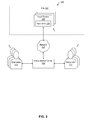
- FIG. 2 is a block diagram illustrating another system for interpreting data from a site
- FIG. 3 is a flow diagram of an embodiment of a method for interpreting data from a site
- FIG. 4 is a block diagram illustrating a system for interpreting data from a site
- FIG. 5 is a flow diagram of an embodiment of a method for interpreting data from a site
- FIG. 6 is a flow diagram of an embodiment of a method for interpreting data from a site
- FIG. 7 is a flow diagram of an embodiment of a method for interpreting data from a site
- FIG. 8 is a flow diagram of an embodiment of a method for interpreting data from a site
- FIG. 9 is a block diagram illustrating an embodiment of a site in which the present systems and methods may be implemented.
- FIG. 10 is a block diagram illustrating an exemplary home automation site in which the present systems and methods may be implemented.
- FIG. 11 is a block diagram illustrating various hardware components that may be used in an embodiment of an embedded device that may be found in the site;
- FIG. 12 is a front view of a block diagram illustrating the various features available on an exemplary site controller
- FIG. 13 is a rear view of a block diagram illustrating the various features available on an exemplary site controller.
- FIG. 14 is a flow diagram of an embodiment of a method for registering site devices at a site.
- a method for interpreting data from a site includes acquiring input data to be interpreted.
- the input data is sent to an interpreter.
- Alert criteria are sent to the interpreter.
- a determination is received that indicates whether the alert criteria was satisfied. If the determination indicates that the alert criteria was satisfied, an alert procedure is performed.
- a system that is configured for interpreting data from a site includes a processor.
- the system also includes memory in electronic communication with the processor. Instructions are stored in the memory.
- the instructions are executable to acquire input data.
- the instructions are also executable to send the input data to an interpreter.
- the instructions are further executable to send alert criteria to the interpreter.
- the instructions are executable to receive a determination that indicates whether the alert criteria was satisfied. If the determination indicates that the alert criteria was satisfied, the instructions are executable to perform an alert procedure.
- the interpretation center is in electronic communication with a plurality of interpreters.
- the interpretation center includes a processor.
- the interpretation center also includes memory in electronic communication with the processor. Instructions are stored in the memory.
- the instructions are executable to register the interpreters with the interpretation center.
- the instructions are also executable to acquire input data that originated from an input device.
- the input device is in electronic communication with the interpretation center.
- the instructions are executable to send the input data to the interpreters.
- the instructions are also executable to send alert criteria to the interpreters.
- the instructions are further executable to receive a determination that indicates whether the alert criteria was satisfied from at least one of the interpreters. If the determination indicates that the alert criteria was satisfied, the instructions are executable to perform an alert procedure.
- the input data is acquired from an input device.
- a visual image is provided to the interpreter.
- the alert criteria includes explicit criteria. In other embodiments, the alert criteria includes implicit criteria. In further embodiments, the alert criteria comprises a list. In other embodiments, the alert criteria comprises a list of statements. In some embodiments, the alert procedure initiates an alert. In other embodiments, the alert procedure cancels an alert.
- the determination that indicates whether the alert criteria was satisfied is stored. In other embodiments, it is determined to which interpreter to send the input data and the alert criteria. In further embodiments, it is determined whether a triggering event was detected.
- a site controller sends the input data to the interpreter.
- a visual image is provided to the interpreter.
- the site controller that receives the input data from the input device and sends the input data to the interpretation center.
- the site controller is an embedded system that includes built-in audio ports, built-in video ports, and built-in infrared in and out ports and wherein the site controller does not require an external exclusive computer monitor for standard operation.
- Such software may include any type of computer instruction or computer executable code located within a memory device and/or transmitted as electronic signals over a system bus or network.
- Software that implements the functionality associated with components described herein may comprise a single instruction, or many instructions, and may be distributed over several different code segments, among different programs, and across several memory devices.
- an embodiment means “one or more (but not necessarily all) embodiments of the disclosed invention(s),” unless expressly specified otherwise.
- determining (and grammatical variants thereof) is used in an extremely broad sense.
- the term “determining” encompasses a wide variety of actions and therefore “determining” can include calculating, computing, processing, deriving, investigating, looking up (e.g., looking up in a table, a database or another data structure), ascertaining and the like.
- determining can include receiving (e.g., receiving information), accessing (e.g., accessing data in a memory) and the like.
- determining can include resolving, selecting, choosing, establishing, and the like.
- FIG. 1 is a block diagram illustrating a system 100 for interpreting data from a site.
- the system 100 may include a site 101 , a network 107 , an interpretation center 102 , and multiple interpreters 111 .
- the site 101 may include a site controller 103 .
- the site controller 103 may include site controller software 122 .
- the site controller software 122 may be used to control the input devices 106 in the site 101 .
- the site controller software 122 may be used to send and/or receive data to and/or from the input devices 106 .
- the site controller software 122 may be used to send and/or receive data to and/or from the interpretation center 102 .
- the system 100 may include multiple input devices 106 .
- the input devices 106 may be used to detect and/or monitor situations at a site 101 .
- the input devices 106 may include input data 124 .
- the input devices 106 may send the input data 124 to the network 107 .
- the input devices 106 may have a connection to a network outside of the control of the site controller 103 .
- the input devices 106 may not have a connection to a network outside of the control of the site controller 103 .
- the input devices 106 may not be in direct electronic communication with the network 107 ; rather, the input devices 106 may connect to the network 107 through the site controller 103 via a site network 108 .
- the site controller 103 may be in electronic communication with the input devices 106 .
- the input devices 106 may communicate with the site controller 103 over the site network 108 .
- the site network 108 may be a wired or wireless network.
- the input devices 106 may communicate with the site controller 103 via an infrared (IR) connection, an Ethernet connection, a wireless connection using the 802.11g (WiFi) standard, a wireless connection using the 802.15.4 (ZigBee) standard, or other wired or wireless connections.
- IR infrared
- WiFi 802.11g
- ZiigBee 802.15.4
- the interpretation center 102 may be in electronic communication with the site 101 via the network 107 .
- the network 107 may include a computer network.
- the network 107 may operate using wired protocols, such as an Ethernet connection; wireless protocols, such as WiFi, ZigBee, Bluetooth, Ultra Wideband, Wimax; cellular protocols, such as GSM or EVDO; and/or any other protocol.
- the site controller 103 is in electronic communication with the interpretation center 102 via the network 107 .
- the interpretation center 102 may include interpretation center software 120 and an interpretation center database 121 .
- the interpreters 111 may use the interpretation center 102 to interpret input data 124 from the site 101 .
- the interpretation center software 120 may be used to facilitate communication between the site controller 103 and the interpretation center 102 .
- the interpretation center software 120 may also be used to determine to which interpreter 111 to send the input data 124 .
- FIG. 2 is a block diagram illustrating a system 100 for interpreting data from a site.
- the system 100 may include a site 101 , a network 107 , an interpretation center 102 , and multiple interpreters 111 .
- the site 101 may include multiple input devices 106 .
- the input devices 106 may be used to detect and/or monitor situations at a site 101 .
- the input devices 106 may include input data 124 .
- the input devices 106 may send the input data 124 to the network 107 .
- the interpretation center 102 may be in electronic communication with the site 101 via the network 107 .
- the network 107 may include a computer network.
- the network 107 may operate using wired protocols, such as an Ethernet connection; wireless protocols, such as WiFi, ZigBee, Bluetooth, Ultra Wideband, Wimax; cellular protocols, such as GSM or EVDO; and/or any other protocol.
- the input devices 106 are in electronic communication with the interpretation center 102 via the network 107 .
- the interpreters 111 may use the interpretation center 102 to interpret input data 124 from the site 101 .
- FIG. 3 is a flow diagram of an embodiment of a method 200 for interpreting data from a site 101 .
- the method 200 may include an input device 106 detecting 202 a triggering event.
- An input device 106 may monitor 204 the site 101 . Monitoring 204 the site 101 may include generating input data 124 . In some embodiments, the site 101 may be monitored 204 in response to a triggering event. In other embodiments, detecting 202 a triggering event may be omitted and an input device 106 may monitor 204 the site 101 periodically, continuously, and/or using other monitoring configurations.
- Input data 124 may be sent 206 to the interpreter 111 .
- the interpreter 111 may interpret 208 the input data 124 .
- Interpreting 208 the input data 124 may include determining whether the input data 124 satisfies predetermined criteria.
- the interpreter 111 may include a human that may interpret input data 124 .
- FIG. 4 is a block diagram illustrating a system 300 for interpreting data from a site 301 .
- the system 300 may include a site 301 , a network 307 , an interpretation center 302 , and multiple interpreters 311 .
- the site 301 may include a site controller 303 .
- the site controller 303 may include site controller software 322 .
- the system 300 may include multiple input devices 106 .
- the input devices 106 may include detection devices 330 and/or monitoring devices 332 .
- Detection devices 330 may be used to detect situations (i.e. alert criteria) at the site 301 .
- Monitoring devices 332 may be used to monitor 204 a site 301 .
- An input device 106 may be both a detection device 330 and/or a monitoring device 332 .
- an input device 106 may be capable of both detecting and/or monitoring situations at a site 301 .
- the detection devices 330 and/or monitoring devices 332 may include input data 324 .
- Input data 324 may include data from the input devices 106 such as sensor data, monitoring data, and/or other input data 324 .
- the site 301 may also include various site devices 304 .
- the input devices 106 may send the input data 324 to the network 307 .
- the site controller 303 may be in electronic communication with the input devices 106 and site devices 304 .
- site devices 304 may include input devices 106 , such as detection devices 330 and/or monitoring devices 332 .
- the site devices 304 may communicate with the site controller 303 over the site network 308 .
- the site network 308 may be a wired or wireless network.
- the site devices 304 may communicate with the site controller 303 via an infrared (IR) connection, an Ethernet connection, a wireless connection using the 802.11g (WiFi) standard, a wireless connection using the 802.15.4 (ZigBee) standard, or other wired or wireless connections.
- IR infrared
- WiFi 802.11g
- ZigBee 802.15.4
- the interpretation center 302 may be in electronic communication with the site 301 via the network 307 .
- the network 307 may operate using wired protocols, wireless protocols, cellular protocols, and/or any other protocol.
- the site controller 303 is in electronic communication with the interpretation center 302 via the network 307 .
- the interpretation center 302 may include interpretation center software 320 and an interpretation center database 321 .
- the interpretation center database 321 may include triggering events 348 , alert criteria 350 , alert procedures 352 , interpreter information 354 , site information 356 , site device information 358 , and/or subscription information 360 .
- Triggering events 348 may include events that may occur at a site 301 .
- Triggering events 348 may be associated with the alert criteria 350 and/or the alert procedures 352 .
- a triggering event 348 may include a motion sensor detecting motion, an IR sensor detecting heat, a perimeter sensor detecting a breach of the perimeter, a smoke and/or carbon monoxide sensor detecting smoke and/or carbon monoxide, an audio sensor detecting sound, a temperature sensor detecting a change in temperature, a water level sensor detecting the level of water, etc.
- the alert criteria 350 may include criteria that may be used by an interpreter 311 to determine whether to perform an alert procedure 352 .
- the alert criteria 350 may include explicit and implicit criteria. Explicit criteria may be less subjective. For example, explicit criteria might include a statement such as “is the window broken?” Implicit criteria may be more subjective. For example, implicit criteria may include “is the area secure?” The alert criteria 350 may include multiple criteria, such as a list.
- the alert procedures 352 may include information such as instructions for an interpreter 311 if the alert criteria 350 are satisfied.
- the alert criteria 350 may include a single statement that an interpreter 311 may determine is true or false.
- the alert criteria 350 may include a list of statements that an interpreter 311 may choose from to determine which is most accurate.
- the alert criteria 350 may be a list of statements, such as does this person look (A) very suspicious, (B) somewhat suspicious, (C) not very suspicious, or (D) not suspicious, from which the interpreter 311 may select the most accurate statement.
- Interpreter information 354 may include information about the interpreter 311 .
- the interpreter information 354 may include the contact information for the interpreter 311 .
- Contact information may include the physical address, telephone number, email address, network address, and/or other contact information for the interpreter 311 .
- the site information 356 may include information about the site 301 .
- the site information 356 may include a prior interpretation history (i.e. data relating to prior site monitoring), various site zones, contact information for the site, the location of the site, and/or other information regarding the site 301 .
- the contact information may include the site telephone number, name of the user, and/or other contact and user information.
- Site device information 358 may include the types of site devices 304 at the site 301 .
- the site device information 358 may include identifications, capabilities, locations, software versions, and other information for each site device 304 .
- the site device information 358 may include which site devices 304 are capable of detecting and/or monitoring the site 301 .
- the subscription information 360 may include information regarding a subscription for the site 301 .
- the user may have a subscription from the site 301 .
- the subscription information 360 may include the duration of the subscription, the type of subscription, and/or other subscription information 360 .
- the subscription information 360 may include the amounts of money that may be paid to an interpreter 311 for interpreting 208 input data 324 .
- the subscription information 360 may include billing information.
- Billing information may include information used to bill a user for a subscription from a site 301 .
- billing information may include credit card information for the user, payment history for the user, and/or other billing information.
- the interpreters 311 may use the interpretation center 302 to interpret input data 324 from the site 301 .
- the interpretation center software 320 may be used to facilitate communication between the site controller 303 and the interpretation center 302 .
- the interpretation center software 320 may be used to determine to which interpreter 311 to send the input data 324 .
- the interpretation center software 320 may be used to determine other information in the interpretation center database 321 .
- the interpretation center software 320 may be used to facilitate communication between the interpreter 311 and the interpretation center 302 .
- FIG. 5 is a flow diagram of an embodiment of a method 400 for interpreting data from a site 101 .
- the method 400 may include a user subscribing 402 to a site monitoring service.
- a site monitoring service may include monitoring a site 101 .
- Subscribing 402 to a site monitoring service may include creating an account with the site monitoring service.
- the user may subscribe 402 to the site monitoring service over the Internet.
- the interpretation center 102 may store the subscription information 360 in the interpretation center database 321 .
- the user may con figure 404 the input devices 106 to monitor the site 101 .
- Configuring 404 the input devices 106 may include determining where to locate the input devices 106 in a site 101 .
- Configuring 404 the input devices 106 may include connecting the input devices 106 to the interpretation center 102 .
- the input devices 106 may be configured 404 to connect directly to the interpretation center 102 and/or indirectly through a site controller 103 .
- Configuring 404 the input devices 106 may include storing the triggering events 348 , alert criteria 350 , and/or alert procedures 352 on the input devices 106 .
- Configuring 404 the input devices 106 may include storing the site information 356 , site device information 358 , and/or any other information in the interpretation center database 321 .
- the input device 106 may be a detection device 330 , such as a motion sensor.
- the motion sensor may be configured 404 with a triggering event 348 .
- the triggering event 348 may occur when the motion sensor detects motion within an area of the site 101 .
- the triggering event 348 may be based on the speed, direction, other aspects of the motion of an object, and/or customizable aspects of the triggering event 348 .
- the triggering event 348 may be determined such that small animals may not satisfy the triggering event 348 .
- the input device 106 may detect 406 a triggering event 348 .
- the motion sensor may detect 406 the movement of a person within a designated area of the site 101 .
- the input device 106 may store the data associated with the detection 406 as input data 124 .
- the input data 124 may be sent to the site controller 103 .
- the input device 106 may monitor 408 the site 101 .
- the input device 106 that detected 406 the triggering event 348 may be the same input device 106 that monitors 408 the site.
- the input device 106 that detected 406 the triggering event 348 may be a different input device 106 than the input device 106 that monitors 408 the site.
- the input device 106 that monitors 408 the site 101 may do so without a triggering event 348 being detected 406 (i.e. continuous, periodic, and/or other monitoring configurations).
- the input device 106 that monitors 408 the site 101 may be a camera.
- the input data 124 may be used to determine that an input device 106 should monitor 408 the site 101 .
- the camera may be instructed to monitor 408 the site 101 .
- the input device 106 may monitor 408 the site 101 for a predetermined amount of time, may take a predetermined number of pictures, etc.
- the data generated by monitoring 408 the site 101 may include input data 124 .
- the pictures taken by the camera while monitoring 408 the site 101 may be input data 124 .
- the data which may include input data 124 , obtained during the detection 406 of a triggering event 348 and/or the monitoring 408 of the site 101 , may be sent 410 to the interpretation center 102 .
- the input data 124 may be sent 410 directly from the site 101 to the interpreter 111 .
- the input data 124 may be sent 410 indirectly to the interpreter 111 .
- the input device 106 may send the input data 124 to the site controller 103 , which may send the input data 124 to the interpretation center 102 , which may send the input data 124 to the interpreter 111 .
- the site controller 103 may receive the input data 124 from the input device 106 and may send 410 the input data 124 to the interpretation center 102 .
- An interpreter 111 may interpret 412 the input data 124 .
- the interpreter 111 may receive input data 124 obtained during the detection 406 of a triggering event 348 or the monitoring 408 of the site 101 and may interpret 412 the input data 124 .
- Interpreting 412 the input data 124 may include looking at the input data 124 .
- the input data 124 may be a picture taken by an input device 106 , such as a camera, while monitoring 408 the site 101 .
- the interpreter 111 may determine 414 whether the input data 124 satisfies the alert criteria 350 .
- the alert criteria 350 may include whether the input data 124 indicates that a person is in the picture taken by the camera.
- the interpreter 111 may interpret 412 the picture by looking at the picture and determining 414 if there is a person in the picture.
- the alert criteria 350 may include whether the person in the picture is authorized to be present at the site, such that the interpreter 111 may compare the picture taken by the camera with pictures of authorized persons that may be stored as site information 356 in the interpretation center database 321 .
- the alert criteria 350 may also include whether the person in the picture looks suspicious.
- Alert criteria 350 may be subjective. Typically, computing devices may have difficulty determining 414 alert criteria 350 that is subjective like, “does the person look suspicious?” In some embodiments, the interpretation center 102 may determine 414 whether the input data 124 satisfies the alert criteria 350 .
- the interpretation center 102 may perform 416 the alert procedure 352 .
- the interpreter 111 may indicate that the alert criteria 350 was satisfied, which may prompt the interpretation center 102 to perform 416 the alert procedure 352 .
- the alert procedure 352 may include notifying the site 101 of an alert.
- the interpretation center 102 may communicate to the site 101 that an unauthorized person has been detected.
- the alert procedure 352 may be performed 416 by the interpreter 111 and/or the site controller 103 .
- the alert procedure 352 may include communicating that the alert criteria 350 have been satisfied to a third party, such as a security service, property management service, and/or other third party.
- the alert procedure 352 may include initiating and/or cancelling an alert.
- the input devices 106 may continue monitoring the site 101 until the input devices 106 detect 406 a triggering event 348 .
- the interpretation center 102 may store any information related to the triggering event 348 , input data 124 , interpretation 412 , and/or other data as site information 356 in the interpretation center database 321 .
- the input device 106 may wait for a period of time before detecting 406 another triggering event 348 .
- FIG. 6 is a flow diagram of an embodiment of a method 500 for interpreting data from a site 101 .
- the method may include a user subscribing 502 to a site monitoring service.
- Subscribing 502 to a site monitoring service may include creating an account with the site monitoring service.
- the user may con figure 504 the various input devices 106 to monitor the site 101 .
- Configuring 504 the input devices 106 may include registering the devices with a site controller 103 .
- Configuring 504 the input devices 106 may include determining where to locate the input devices 106 in a site 101 ; connecting the input devices 106 to the interpretation center 102 ; storing the triggering events 348 , alert criteria 350 , and/or alert procedures 352 on the input devices 106 ; storing the site information 356 , site device information 358 , and/or any other information in the interpretation center database 321 ; and/or other configuration processes.
- a triggering event 348 may include an event that may occur at a site 101 . Triggering events 348 may be associated with the alert criteria 350 and/or the alert procedures 352 .
- a triggering event 348 may include a motion sensor detecting motion, an IR sensor detecting heat, a perimeter sensor detecting a breach of the perimeter, a smoke and/or carbon monoxide sensor detecting smoke and/or carbon monoxide, an audio sensor detecting sound, a temperature sensor detecting a change in temperature, a water level sensor detecting the level of water, etc.
- the triggering event 348 may be based on the speed, direction, other aspects of the motion of an object, and/or customizable aspects of the triggering event 348 .
- An alert procedure 352 may include information such as instructions for an interpreter 111 if the alert criteria 350 are satisfied.
- the alert procedure 352 may include notifying the site 101 of an alert.
- the interpretation center 102 may communicate to the site 101 that an unauthorized person has been detected.
- the alert procedure may be performed 416 by the interpreter 111 and/or the site controller 103 .
- FIG. 7 is a flow diagram of an embodiment of a method 600 for interpreting data from a site 101 .
- the method 600 may include an interpreter registering 602 with the interpretation center 102 .
- Registering 602 with the interpretation center 102 may include providing contact information, such as an address, telephone number, etc.
- Registering 602 with the interpretation center 102 may include providing a username and password.
- Registering 602 with the interpretation center 102 may include providing a network address, email address, and/or other electronic address information.
- Registering 602 with the interpretation center 102 may include providing payroll information, tax information, and/or other business information.
- the interpretation center 102 may receive 604 input data 124 .
- the interpretation center 102 may receive 604 input data 124 directly and/or indirectly from an input device 106 .
- the input device 106 may send the input data 124 indirectly to the interpretation center 102 by sending the input data 124 to a site controller 103 and the site controller 103 may send 410 the input data 124 to the interpretation center 102 .
- the interpretation center 102 may determine 606 to which interpreter 111 to send 608 the input data 124 .
- the interpretation center 102 may consider interpreter information 354 to determine 606 to which interpreter 111 to send 608 the input data 124 .
- the interpretation center 102 may consider the interpreter's experience, background, past assignments, service reviews, and/or other interpreter information 354 in determining 606 to which interpreter 111 to send 608 the input data 124 .
- the interpretation center 102 may send 608 input data 124 to the interpreter 111 .
- the interpretation center 102 may consider the interpreter information 354 to determine which method to use to send 608 the input data 124 .
- the interpretation center 102 may send 608 input data 124 to the interpreter 111 via the Internet, email, cellular technologies, wireless, etc.
- the interpretation center 102 may notify the interpreter 111 that input data 124 has been received and needs to be interpreted.
- the input data 124 may be sent only to interpreters 111 that are currently available to receive input data 124 .
- the input data 124 may be sent to multiple interpreters 111 until the input data 124 has been adequately interpreted.
- the input data 124 may be sent to multiple interpreters 111 until a predetermined number, percentage, and/or some other criteria of determinations is satisfied.
- the alert criteria 350 may specify that a predetermined percentage of determinations must be made before the alert criteria 350 is satisfied, such that when, for example, 80% of the received determinations indicate a certain response, the alert criteria 350 may be satisfied.
- the interpreter 111 may interpret 610 the input data 124 .
- Interpreting 610 the input data 124 may include determining whether the input data 124 satisfies predetermined criteria. For example, interpreting 610 the input data 124 may include reviewing the input data 124 in preparation for determining 612 whether the input data 124 satisfies the alert criteria 350 .
- Interpreting 610 the input data 124 generally includes steps that are not typically performed well and/or inexpensively by a computer or other machine.
- the interpreter 111 may perform 614 the alert procedure 352 .
- Performing 614 the alert procedure 352 may include contacting the site 101 , using site devices 304 to alert users at the site 101 , and/or other alert procedures 352 .
- the alert procedure 352 may be performed 614 by the interpreter 111 and/or the site controller 103 .
- the interpretation center 102 may communicate to the site 101 , the fire department, and/or a third party service that a fire has been detected.
- the interpretation center 102 may also communicate with a site controller 103 , in response to the alert procedure 352 .
- the interpretation center 102 may instruct the site controller 103 to turn on lights at the site 101 , turn off all ventilation systems, send an audio announcement over audio enabled site devices 304 , turn anti-fire systems (i.e. sprinklers, etc.) on, and/or other alert procedures 352 .
- FIG. 8 is a flow diagram of an embodiment of a method 700 for interpreting data from a site 101 .
- the method 700 may include a user configuring 702 the input devices 106 to monitor the site 101 .
- Configuring 702 the input devices 106 may include determining where to locate the input devices 106 in a site.
- Configuring 702 the input devices 106 may include connecting the input devices 106 indirectly to the interpretation center 102 through a site controller 103 .
- Configuring 702 the input devices 106 may include storing the triggering events 348 , alert criteria 350 , and/or alert procedures 352 on the input devices 106 and/or the site controller 103 .
- Configuring 702 the input devices 106 may include storing the site information 356 , site device information 358 , and/or any other information in the interpretation center database 321 .
- a detection device 330 may detect 406 a triggering event 348 and may send input data 124 relating to the detection 406 to the site controller 103 .
- the site controller 103 may determine 704 that the received input data 124 indicates that a triggering event 348 was detected 406 .
- a site device 304 may be a detection device 330 .
- the detection device 330 may be a water sensor in a basement.
- the triggering event 348 may be if the water sensor detects water above a certain level in the basement.
- the site controller 103 may be notified 706 of the triggering event 348 .
- the site controller 103 may be notified 706 of the triggering event 348 by the input device 106 that detected the triggering event 348 .
- Notifying 706 of the triggering event 348 may include sending the input data 124 .
- a monitoring request may be sent 708 to an input device 106 .
- the site controller 103 may send 708 the monitoring request to an input device 106 .
- a monitoring request may include requesting that an input device 106 begin monitoring a portion of the site 101 .
- An input device 106 may monitor 710 the site 101 .
- the input device 106 that received a monitor request may monitor 710 the site 101 .
- Monitoring 710 the site 101 may include recording audio and/or video data, taking still pictures, recording temperature data, recording humidity data, and/or other monitoring processes.
- Monitoring 710 the site 101 may include storing input data 124 relating to monitoring 710 the site 101 .
- the input data 124 may be sent.
- the input data 124 is sent 712 by the input device 106 to the site controller 103 .
- the site controller 103 may send 714 the input data 124 to the interpretation center 102 .
- the site controller 103 may determine 716 whether an alert procedure 352 was activated. Determining 716 whether an alert procedure 352 was activated may include reviewing data received from the interpretation center 102 to determine 716 whether an alert procedure 352 was activated.
- Alert procedures 352 may be received 718 .
- the site controller 103 may receive 718 an alert procedure 352 .
- Receiving 718 alert procedures 352 may include receiving instructions from the interpretation center 102 regarding an activated alert procedure 352 .
- the alert procedures 352 may be processed 720 .
- the site controller 103 may process 720 the alert procedures 352 .
- Processing 720 the alert procedures 352 may include turning on lights at the site 101 , turning off all ventilation systems, sending an audio announcement over audio enabled site devices 304 , turning anti-fire systems (i.e. sprinklers, etc.) on, and/or performing other alert procedures 352 .
- FIG. 9 is a block diagram illustrating an embodiment of a site 801 in which the present systems and methods may be implemented.
- the site 801 in the present embodiment, includes a site controller 803 and other site devices 304 .
- the site controller 803 may be in electronic communication with the site devices 304 .
- a site 801 may include multiple site controllers 103 , but typically requires that one of the site controllers 103 is designated as the primary site controller 803 .
- the site controller 803 may be connected to the site devices 304 via wireless or wired connections.
- the site controller 803 may be connected to the site devices via an Ethernet connection 826 , a WiFi connection 827 , a ZigBee connection 828 , or a combination of the three.
- the site controller 803 may be capable of communicating via these network connections, i.e. Ethernet, WiFi, or ZigBee connections 826 , 827 , 828 or other connections.
- the site devices 304 may include lighting devices 812 , temperature control devices 813 , security system devices 814 , intercom system devices 815 , audio devices 816 , video devices 817 , landscape devices 818 , and control devices 819 .
- Lighting devices 812 may include light switches, dimmers, window blinds, etc.
- Temperature control devices 813 may include thermostats, fans, fireplaces, and the like.
- Security system devices 814 may include security cameras, motion detectors, door sensors, window sensors, gates, or other security devices.
- Intercom system devices 815 may include intercom microphones, intercom related video devices, and other devices typically associated with an intercom system.
- Audio devices 816 may include AM/FM radio receivers, XM radio receivers, CD players, MP3 players, cassette tape players, and other site devices 304 capable of producing an audio signal.
- Video devices 817 may include televisions, monitors, projectors, and other site devices 304 capable of producing a video signal.
- Landscape devices 818 may include sprinkler system devices, drip system devices, and other landscape related devices.
- the control devices 819 may include touch screens, keypads, and remote controls. For example, control devices 819 may include site remote controls, LCD keypads, mini touch screens, or other control devices 819 capable of controlling a site controller 103 .
- FIG. 10 is a block diagram illustrating an exemplary home automation site 901 in which the present systems and methods may be implemented.
- the home automation site 901 may include various areas, such as a living room 942 , kitchen 944 , den 945 , and a patio 946 .
- other sites 101 may also implement the present systems and methods.
- the present systems and methods may be implemented in an office building, warehouse, or other site 101 .
- a site 101 may not be limited to a particular building or space. Rather, a site 101 may include a site controller 103 and various site devices 304 in electronic communication with the site controller 103 .
- a home for example, may include more than one site 101 .
- multiple site controllers 103 may be used within the same site, though one site controller 103 is typically designated as the primary site controller 903 .
- Additional site devices 304 may also be used in the present embodiment of a site 901 .
- the security system devices 814 may include input devices 106 .
- the input devices 106 may include detection devices 930 and/or monitoring devices 932 .
- Other security system devices 814 may also be used.
- the audio devices 816 include speakers 949 and speaker points 939 .
- control devices 819 may include site remote controls 924 , LCD keypads 937 , mini touch screens 938 , or other control devices 819 .
- the lighting devices 812 may include switch/dimmers 933 and outlet switch/dimmers 934 .
- Other lighting devices 812 and landscape devices 818 may also be used with the present systems and methods.
- the site controller 903 in the present embodiment of a site 901 , may be located in the den 945 .
- the site controller 903 may be in electronic communication with various site devices 304 over the site network 108 .
- some site devices 304 such as audio switches, amplifiers, and tuners may be connected to the site controller 903 via Ethernet connections 826 .
- Site remote controls 924 may be connected to the site controller 903 via ZigBee connections 828 .
- Switch/dimmers 933 , outlet switch/dimmers 934 , multiple button keypads (not shown), and LCD keypads 937 may be connected to the site controller 903 via Ethernet connections 826 and ZigBee connections 828 .
- Mini touch screens 938 and contact relay extenders 935 may be connected to the site controller 903 via an Ethernet connection 826 , a ZigBee connection 828 , and a WiFi connection 827 .
- Speaker points 939 may be connected to the site controller 903 via an Ethernet connection 826 and a WiFi connection 827 .
- Touch screens 940 may be connected to the site controller 903 via a ZigBee connection 828 and a WiFi connection 827 .
- the detection devices 930 and/or monitoring devices 932 may be connected to the site controller 903 via a contact relay extender, an Ethernet connection 826 , a ZigBee connection 828 , and/or a WiFi connection 827 .
- the den 945 may include the site controller 903 , a switch/dimmer 933 , an outlet switch/dimmer 934 , and speakers 949 .
- the speakers 949 in the den 945 may be connected directly to the site controller 903 .
- a site remote control 924 and a touch screen 940 may also be located in the den 945 .
- speakers 949 that are not directly connected to the site controller 903 may be connected to one of the speaker points 939 .
- the speaker points 939 may allow the speakers 949 not directly connected to the site controller 903 to be controlled by the site controller 903 .
- the site controller 903 may transmit audio signals to the speakers 949 via the speaker points 939 .
- the audio signals in the present embodiment, may be transmitted to the speaker points 939 over an Ethernet connection 826 or a WiFi connection 827 .
- any connection capable of the bandwidth necessary to transmit audio signals may be used. Similar connections may be used for transmitting video signals over a site 901 .
- the site remote control 924 and touch screen 940 in the den 945 , the LCD keypads 937 located in the living room 942 and on the patio 946 , and the mini touch screen 938 located in the kitchen 944 may be used to control all of the site devices 304 in the site 901 that are connected to the site controller 903 .
- the LCD keypad 937 in the living room 942 may control the site controller 903 in the den 945 to play music over the speakers 949 in the living room 942 via the speaker point 939 in the living room 942 .
- the LCD keypad 937 in the living room 942 may also, for example, control the site controller 903 in the den 945 to play music over all speakers 949 in the site 901 via their respective speaker points 939 or a direct connection to the site controller 903 .
- Typical devices like the window blinds, fireplaces, or sprinkler systems may not be capable of communication using an Ethernet, WiFi, or ZigBee connection 826 , 827 , 828 .
- the contacts, relays, or other connections that control their function may be connected to a site device 304 that is capable of communication with a site controller 903 .
- FIG. 11 is a block diagram illustrating various hardware components that may be used in an embodiment of an embedded device 1005 that may be found in the site 101 .
- the site controller 103 , input devices 106 , site devices 304 , and control devices 819 may be embedded devices 1005 .
- the embedded device 1005 may include a processor 1063 that is in electronic communication with memory 1064 .
- the memory 1064 may include volatile and/or non-volatile memory.
- the embedded device 1005 may include a power supply 1065 .
- the embedded device 1005 may include a CD-RW drive 1066 .
- the CD-RW drive 1066 may not be a writeable drive, but may only be a CD-ROM drive.
- the CD-RW drive 1066 may be a DVD-RW or a DVD-ROM drive.
- the CD-RW drive 1066 may also be a Blu-ray disk or a HD DVD drive.
- the embedded device 1005 may be capable of using the CD-RW drive 1066 to rip audio or video data from CDs and DVDs.
- the embedded device 1005 may include a network interface 1067 that allows the embedded device 1005 to connect using wired connections, such as Ethernet connections 826 .
- the network interface 1067 may use various protocols to enable the embedded device 1005 to interface with any wired network.
- the embedded device 1005 may include wireless transceivers 1068 .
- the embedded device 1005 may include a WiFi transceiver and a ZigBee transceiver.
- the embedded device 1005 may include any type of wireless transceiver 1068 .
- the wireless transceiver 1068 may allow the embedded device 1005 to transmit and receive data using any wireless protocol, such as WiFi, ZigBee, Bluetooth, Ultra Wideband, Wimax, and/or cellular protocols, such as GSM or EVDO.
- the embedded device 1005 may include I/O interfaces 1069 .
- the I/O interfaces 1069 may include inputs and/or outputs such as buttons, selection dials, serial ports, contact ports, relay ports, IR windows, IR ports, video sense loop ports, audio ports, and video ports.
- the embedded device 1005 may include communication ports 1070 .
- the communication ports 1070 may include USB ports, firewire ports, or other ports for communicating with other devices.
- Some site controllers 103 and site devices 304 may not include all of the illustrated components. Other site controllers 103 and site devices 304 may include additional components. For example, many site devices 304 may not include a CD-RW drive 1066 .
- FIG. 12 is a front view of a block diagram illustrating the various features available on an exemplary site controller 1103 . Specifically, FIG. 12 shows the front of an exemplary site controller 1103 .
- the site controller 1103 may include a display area 1172 .
- the display area 1172 in the present embodiment may be used to display settings, playlist sections, title sections, media information, receiver status, and system menus.
- the site controller 1103 may also include various buttons 1173 for selecting options displayed in the display area 1172 .
- the site controller 1103 may also include an IR in window 1174 .
- the IR in window 1174 may be used to receive IR codes from the site remote control 924 or from any other device capable of sending IR signals, including other remote controls (not shown) used to control devices that are not capable of communication with the site controller 1103 .
- the site controller 1103 may include a selection dial 1175 .
- the selection dial 1175 may be used to scroll through menus and media lists displayed in the display area 1172 .
- the site controller 1103 may include a reset button 1176 .
- the reset button 1176 may be used to refresh the site controller software 122 .
- the site controller 1103 may also include a WiFi antenna 1177 .
- the WiFi antenna 1177 may be used with an extender (not shown) to improve reception of wireless signals.
- a ZigBee antenna (not shown) may also be used to extend the range of a wireless transceiver 1068 using a ZigBee connection 828 .
- the site controller 1103 may also include a CD-RW drive 1166 .
- the CD-RW drive 1166 may be replaced with any drive that is capable of playing CD or DVD related media.
- the CD-RW drive 1166 may be used to import CD or DVD data into the memory 1064 of the site controller 1103 .
- the site controller 1103 may also include a USB port 1178 .
- the USB port 1178 may be used to import data from USB enabled devices.
- FIG. 13 is a rear view of a block diagram illustrating the various features available on an exemplary site controller 1203 . Specifically, FIG. 13 shows the back of an exemplary site controller 1203 . Most connectors and ports are typically found on the back of the site controller 1203 leaving the front more aesthetically pleasing. However, the location of the various connectors and ports is typically not functionally important.
- the site controller 1203 may include serial ports 1279 .
- the serial ports 1279 may include standard serial ports and configurable serial ports.
- the standard serial ports may be used for RS-232 or other I/O devices, which include hardware flow control.
- the site controller 1203 may include two standard serial ports.
- the configurable serial ports may be used for RS-232, RS-422, or RS-485 devices or for other serial I/O devices.
- the site controller 1203 may include two configurable serial ports.
- the site controller 1203 may include contact ports 1280 .
- the contact ports 1280 may include a pluggable terminal block connector that may be used for dry contact closure, or logic input connections, such as door switches or motion sensors.
- the site controller 1203 may include six contact ports 1280 .
- the site controller 1203 may include relay ports 1281 .
- the relay ports 1281 may include a pluggable terminal block connector that may be used for normally closed or normally opened switchable connections, such as blinds, fireplace, or projector screens.
- the site controller 1203 may include six relay ports 1281 .
- the site controller 1203 may include IR ports 1282 .
- the IR ports 1282 may include IR in ports and IR out ports.
- the IR in ports may include a pluggable terminal block connector that may be used for handheld IR devices, such as device specific remote controls (not shown).
- the site controller 1203 may include four IR in ports.
- the IR out ports may include 3.5 mm earphone jacks.
- the IR out ports may be used for IR sticky emitters that can be placed over IR readers on media players, TVs, or other targets to transmit an IR signal from site controller 1203 to the target.
- the site controller 1203 may include eight IR out ports.
- the site controller 1203 may include video sense loop in/out ports 1283 .
- the video sense loop in/out ports 1283 may be composite ports for video sources, such as DVD players or VCRs, which allow the site controller 1203 to detect the On/Off status of devices that use the same IR code for both on and off commands.
- the site controller 1203 in the present embodiment, may include four pairs of video sense loop in/out ports 1283 (four in and four out).
- the site controller 1203 may include an Ethernet connector 1284 for establishing an Ethernet connection 826 with the site devices 304 in a site 101 .
- the Ethernet connector 1284 may be connected to the network interface 1067 on the site controller 1203 .
- the Ethernet connector 1284 may be an RJ-45 for a 10/100 BaseT Ethernet connector.
- the site controller 1203 may include an additional USB port 1278 on the back of the site controller 1203 .
- a modem port 1285 may be included with the site controller 1203 .
- the modem port 1285 may be an RJ-11 port for a modem to support caller ID or a voice menu system.
- the site controller 1203 may also include audio in/out ports 1286 .
- the audio in ports may be RCA jacks for stereo channel input for stereo analog sources.
- the site controller may include three audio in ports.
- the audio out ports may be RCA jacks for stereo channel output.
- the site controller 1203 may include three audio out ports.
- the audio in/out ports 1286 may include digital audio in/out ports.
- the digital audio in/out ports may be designed for a ToslinkTM optical cable for digital audio in/out, like MP3 players, CD players, DVD players, etc.
- the site controller 1203 may include various video ports 1287 .
- the video ports 1287 may be in/out ports and may include composite video ports, S-Video ports, component video ports, and/or VGA ports.
- the video ports 1287 may be used to display navigation menus on a monitor or TV.
- the video ports 1287 include a composite video out port, an S-Video out port, a component video out port, and a VGA out port.
- a power plug port 1288 may be included in the site controller 1203 .
- the site controller 1203 is different than a personal computer for a number of reasons.
- the site controller 1203 is an embedded system that is specialized for the functions and purposes set forth herein.
- the site controller 1203 generally does not include a keyboard or mouse for standard operation.
- the site controller 1203 may not contain an expandable motherboard.
- the site controller 1203 may not include expandable memory slots or expandable ports, such as a PCI, AGP, or PCI Express card slot.
- the site controller 1203 may also not have an exclusive computer monitor.
- typically a personal computer may include a relatively large monitor or display that is primarily for viewing an operating system user interface and executed programs.
- the site controller 1203 may merely use a television or monitor for brief periods of time, although the television or monitor may primarily be used for viewing television programming, DVDs, etc. In another example, the site controller 1203 may be used without a separate monitor; the site controller 1203 may use the display area 1272 . Typically, a personal computer with such a small display area would be incapable of the multiple interfaces and ports that may be found on a site controller 1203 .
- the site controller 1203 may also not have the capability to install and run third party software, such as word processing software.
- the site controller 1203 typically does not allow a user to install and run third party software on the controller 1203 . Unlike a personal computer, a typical user generally could not install a different operating system on the site controller 1203 .
- FIG. 14 is a flow diagram of an embodiment of a method 1300 for registering site devices 304 at a site 101 .
- a site device 304 may be added 1332 to the site 101 .
- a switch/dimmer 933 may be installed in a home or a thermostat may be installed in an office building.
- a site remote control 924 or LCD keypad 937 may be installed in a home or office.
- adding 1332 a device to a site 101 may include connecting the device over an Ethernet connection 826 .
- the user may connect 1334 the device with the site controller 103 . Connecting 1334 the device with the site controller 103 may include turning on the device to enable wired or wireless communication with the site controller 103 .
- the user may store 1336 a device identification for the site device 304 on the site controller 103 by accessing the site controller 103 .
- the device identification may be stored in a site database on the site controller 103 .
- the site controller 103 may store 1338 the device functionality of the site device 304 .
- the device functionality may be stored in the device database on the site controller 103 .
- the site controller 103 may store 1340 a device type for the site device 304 on the site controller 103 (e.g., in the device database on the site controller 103 ).
- the site controller 103 may store 1342 the connection types available for the site device 304 on the site controller 103 .
- the site device 304 is capable only of an Ethernet connection 826 and a ZigBee connection 828 , this may be stored 1342 on the site controller 103 .
- the site controller 103 may store 1344 the location of the site device 304 .
- the device location may indicate if the site device 304 is located in the living room 942 , kitchen 944 , den 945 , or on the patio 946 , etc.
- the device identification, device type, available connection types i.e., an Ethernet connection 826 , a WiFi connection 827 , a ZigBee connection 828 , or other connection types
- device location may be stored 1336 , 1338 , 1340 , 1342 , 1344 in the device database on the site controller 103 .
- the site controller 103 may determine and store the device identification, device type, device functionality, available connection types, or device location without user input. For example, the site controller 103 may attempt to determine the available connection types by pinging the site device 304 , the device location by comparing the device's response time to requests, the device type or device functionality by attempting to perform functions typically performed by the various device types, etc.
- Information and signals may be represented using any of a variety of different technologies and techniques.
- data, instructions, commands, information, signals, bits, symbols, and chips that may be referenced throughout the above description may be represented by voltages, currents, electromagnetic waves, magnetic fields or particles, optical fields or particles, or any combination thereof.
- DSP digital signal processor
- ASIC application specific integrated circuit
- FPGA field programmable gate array signal
- a general purpose processor may be a microprocessor, but in the alternative, the processor may be any conventional processor, controller, microcontroller, or state machine.
- a processor may also be implemented as a combination of computing devices, e.g., a combination of a DSP and a microprocessor, a plurality of microprocessors, one or more microprocessors in conjunction with a DSP core, or any other such configuration.
- Web services may include software systems designed to support interoperable machine-to-machine interaction over a computer network, such as the Internet. Web services may include various protocols and standards that may be used to exchange data between applications or systems.
- the web services may include messaging specifications, security specifications, reliable messaging specifications, transaction specifications, metadata specifications, XML specifications, management specifications, and/or business process specifications. Commonly used specifications like SOAP, WSDL, XML, and/or other specifications may be used.
- a software module may reside in RAM memory, flash memory, ROM memory, EPROM memory, EEPROM memory, registers, hard disk, a removable disk, a CD-ROM, or any other form of storage medium known in the art.
- An exemplary storage medium is coupled to the processor such that the processor can read information from, and write information to, the storage medium.
- the storage medium may be integral to the processor.
- the processor and the storage medium may reside in an ASIC.
- the ASIC may reside in a user terminal.
- the processor and the storage medium may reside as discrete components in a user terminal.
- the methods disclosed herein comprise one or more steps or actions for achieving the described method.
- the method steps and/or actions may be interchanged with one another without departing from the scope of the present invention.
- the order and/or use of specific steps and/or actions may be modified without departing from the scope of the present invention.
Abstract
Description
Claims (28)
Priority Applications (1)
| Application Number | Priority Date | Filing Date | Title |
|---|---|---|---|
| US11/669,062 US8072322B1 (en) | 2007-01-30 | 2007-01-30 | Interpreting data from a site |
Applications Claiming Priority (1)
| Application Number | Priority Date | Filing Date | Title |
|---|---|---|---|
| US11/669,062 US8072322B1 (en) | 2007-01-30 | 2007-01-30 | Interpreting data from a site |
Publications (1)
| Publication Number | Publication Date |
|---|---|
| US8072322B1 true US8072322B1 (en) | 2011-12-06 |
Family
ID=45034416
Family Applications (1)
| Application Number | Title | Priority Date | Filing Date |
|---|---|---|---|
| US11/669,062 Active 2030-01-09 US8072322B1 (en) | 2007-01-30 | 2007-01-30 | Interpreting data from a site |
Country Status (1)
| Country | Link |
|---|---|
| US (1) | US8072322B1 (en) |
Cited By (6)
| Publication number | Priority date | Publication date | Assignee | Title |
|---|---|---|---|---|
| US20170302741A1 (en) * | 2015-11-11 | 2017-10-19 | ARK-LA-TEX Remote Monitoring and Control, LLC | Systems and methods for process monitoring and control |
| US20180342139A1 (en) * | 2018-05-11 | 2018-11-29 | Louis Ukuni Otavio | Lifesaverhd: a computer hardware and software program for safety, detection, alert system and asset tracking |
| US10834201B2 (en) * | 2018-11-27 | 2020-11-10 | International Business Machines Corporation | Device identification and reconfiguration in a network |
| US11170622B2 (en) * | 2019-04-25 | 2021-11-09 | Drägerwerk AG & Co. KGaA | Device and process for monitoring sound and gas exposure |
| US11392841B2 (en) | 2017-10-20 | 2022-07-19 | Hartford Fire Insurance Company | System to monitor and process water-related data |
| USD999176S1 (en) | 2021-07-29 | 2023-09-19 | Ohc Ip Holdings, Llc | Outdoor electronics enclosure |
Citations (6)
| Publication number | Priority date | Publication date | Assignee | Title |
|---|---|---|---|---|
| US20020080938A1 (en) * | 2000-05-19 | 2002-06-27 | Alexander Wade H. | Method and apparatus for generating dynamic graphical representations and real-time notification of the status of a remotely monitored system |
| US6710715B2 (en) * | 2001-01-25 | 2004-03-23 | Douglas Arthur Deeds | Alarm system with integrated weather alert function |
| US6833787B1 (en) * | 1999-10-07 | 2004-12-21 | Asap Software Express, Inc. | Method and system for device tracking |
| US6847892B2 (en) * | 2001-10-29 | 2005-01-25 | Digital Angel Corporation | System for localizing and sensing objects and providing alerts |
| US20050134450A1 (en) * | 2003-12-23 | 2005-06-23 | Honeywell International, Inc. | Integrated alarm detection and verification device |
| US7643834B2 (en) * | 2001-07-16 | 2010-01-05 | Wavemarket, Inc. | System for providing alert-based services to mobile stations in a wireless communications network |
-
2007
- 2007-01-30 US US11/669,062 patent/US8072322B1/en active Active
Patent Citations (6)
| Publication number | Priority date | Publication date | Assignee | Title |
|---|---|---|---|---|
| US6833787B1 (en) * | 1999-10-07 | 2004-12-21 | Asap Software Express, Inc. | Method and system for device tracking |
| US20020080938A1 (en) * | 2000-05-19 | 2002-06-27 | Alexander Wade H. | Method and apparatus for generating dynamic graphical representations and real-time notification of the status of a remotely monitored system |
| US6710715B2 (en) * | 2001-01-25 | 2004-03-23 | Douglas Arthur Deeds | Alarm system with integrated weather alert function |
| US7643834B2 (en) * | 2001-07-16 | 2010-01-05 | Wavemarket, Inc. | System for providing alert-based services to mobile stations in a wireless communications network |
| US6847892B2 (en) * | 2001-10-29 | 2005-01-25 | Digital Angel Corporation | System for localizing and sensing objects and providing alerts |
| US20050134450A1 (en) * | 2003-12-23 | 2005-06-23 | Honeywell International, Inc. | Integrated alarm detection and verification device |
Non-Patent Citations (5)
| Title |
|---|
| "Amazon's Mechanical Turk," http://blog.outer-court.com/archive/2005-11-04-n69.html, pp. 1-2. |
| "CHI Image Sorting," http://blog.outer-court.com/archive/2005-03-28-n53.html, pp. 1-4. |
| "CHI, a Collaborative Human Interpreter," http://blog.outer-court.com/archive/2005-03-25-n43.html, pp. 1-5. |
| "Collaborative human interpreter," http://en.wikipedia.org/wiki/Collaborative-human-interpreter, May 2006. |
| "Mycroft-Technology Needs People," http://mycroftnetwork.com/, pp. 1-2, Accessed Sep. 1, 2006. |
Cited By (6)
| Publication number | Priority date | Publication date | Assignee | Title |
|---|---|---|---|---|
| US20170302741A1 (en) * | 2015-11-11 | 2017-10-19 | ARK-LA-TEX Remote Monitoring and Control, LLC | Systems and methods for process monitoring and control |
| US11392841B2 (en) | 2017-10-20 | 2022-07-19 | Hartford Fire Insurance Company | System to monitor and process water-related data |
| US20180342139A1 (en) * | 2018-05-11 | 2018-11-29 | Louis Ukuni Otavio | Lifesaverhd: a computer hardware and software program for safety, detection, alert system and asset tracking |
| US10834201B2 (en) * | 2018-11-27 | 2020-11-10 | International Business Machines Corporation | Device identification and reconfiguration in a network |
| US11170622B2 (en) * | 2019-04-25 | 2021-11-09 | Drägerwerk AG & Co. KGaA | Device and process for monitoring sound and gas exposure |
| USD999176S1 (en) | 2021-07-29 | 2023-09-19 | Ohc Ip Holdings, Llc | Outdoor electronics enclosure |
Similar Documents
| Publication | Publication Date | Title |
|---|---|---|
| US7738870B2 (en) | Systems and methods for instant messaging using a control device | |
| US10917618B2 (en) | Providing status information for secondary devices with video footage from audio/video recording and communication devices | |
| US20220329762A1 (en) | Methods and Systems for Presenting Smart Home Information in a User Interface | |
| US10558323B1 (en) | Systems and methods for smart home automation using a multifunction status and entry point icon | |
| US20220114880A1 (en) | Securing Property | |
| US10217090B2 (en) | Methods for providing notifications for follow-up actions in response to events detected by an automation system, and systems and devices related thereto | |
| US9882989B2 (en) | Systems and methods for providing remote assistance for controlling a site | |
| US10263802B2 (en) | Methods and devices for establishing connections with remote cameras | |
| US10630943B1 (en) | Smart surveillance systems | |
| US10540884B1 (en) | Systems and methods for operating remote presence security | |
| US7991866B2 (en) | Systems and methods for updating a site | |
| JP5634964B2 (en) | Method, system and computer program product for automatically managing components in a controlled environment | |
| US8072322B1 (en) | Interpreting data from a site | |
| US8441350B2 (en) | Apparatus and method for operation of a display device to provide a home security alarm | |
| US11153637B2 (en) | Sharing video footage from audio/video recording and communication devices to smart TV devices | |
| JP2022546438A (en) | Method, electronic device, server system, and program for providing event clips | |
| US8761712B1 (en) | Location based remote controller for controlling different electronic devices located in different locations | |
| US20230119043A1 (en) | Operating-system-level permission management for multi-ecosystem smart-home devices | |
| US8170183B2 (en) | Systems and methods for providing a message service for a site | |
| JP2002142271A (en) | Remote control system for electronic and electric equipment | |
| CN110995551A (en) | Storage medium, intelligent panel and interaction method thereof | |
| KR20160033390A (en) | Crime and Disaster Prevention System and Operating Method thereof | |
| CN111126163A (en) | Intelligent panel, interaction method based on face angle detection and storage medium | |
| CN105791918A (en) | Home audio video display device (AVDD) as sensor monitor | |
| WO2023069622A1 (en) | Operating-system-level permission management for multi-ecosystem smart home devices |
Legal Events
| Date | Code | Title | Description |
|---|---|---|---|
| AS | Assignment |
Owner name: CONTROL4 CORPORATION, UTAH Free format text: ASSIGNMENT OF ASSIGNORS INTEREST;ASSIGNOR:HOWARD, MICHAEL L.;REEL/FRAME:018849/0648 Effective date: 20070129 |
|
| STCF | Information on status: patent grant |
Free format text: PATENTED CASE |
|
| CC | Certificate of correction | ||
| FPAY | Fee payment |
Year of fee payment: 4 |
|
| FEPP | Fee payment procedure |
Free format text: ENTITY STATUS SET TO UNDISCOUNTED (ORIGINAL EVENT CODE: BIG.); ENTITY STATUS OF PATENT OWNER: LARGE ENTITY |
|
| MAFP | Maintenance fee payment |
Free format text: PAYMENT OF MAINTENANCE FEE, 8TH YEAR, LARGE ENTITY (ORIGINAL EVENT CODE: M1552); ENTITY STATUS OF PATENT OWNER: LARGE ENTITY Year of fee payment: 8 |
|
| AS | Assignment |
Owner name: UBS AG, STAMFORD BRANCH, AS COLLATERAL AGENT, CONN Free format text: SECURITY INTEREST;ASSIGNOR:CONTROL4 CORPORATION;REEL/FRAME:049948/0911 Effective date: 20190801 Owner name: UBS AG, STAMFORD BRANCH, AS COLLATERAL AGENT, CONNECTICUT Free format text: SECURITY INTEREST;ASSIGNOR:CONTROL4 CORPORATION;REEL/FRAME:049948/0911 Effective date: 20190801 |
|
| AS | Assignment |
Owner name: WIREPATH HOME SYSTEMS, LLC, NORTH CAROLINA Free format text: ASSIGNMENT OF ASSIGNORS INTEREST;ASSIGNOR:CONTROL4 CORPORATION;REEL/FRAME:051446/0868 Effective date: 20191220 |
|
| AS | Assignment |
Owner name: SNAP ONE, LLC, UTAH Free format text: CHANGE OF NAME;ASSIGNOR:WIREPATH HOME SYSTEMS, LLC;REEL/FRAME:057298/0014 Effective date: 20210623 |
|
| AS | Assignment |
Owner name: MORGAN STANLEY SENIOR FUNDING INC., MARYLAND Free format text: SECURITY INTEREST;ASSIGNOR:SNAP ONE, LLC;REEL/FRAME:058439/0014 Effective date: 20211208 Owner name: CONTROL4 CORPORATION, UTAH Free format text: RELEASE BY SECURED PARTY;ASSIGNOR:UBS AG, STAMFORD BRANCH;REEL/FRAME:058438/0975 Effective date: 20211208 |
|
| MAFP | Maintenance fee payment |
Free format text: PAYMENT OF MAINTENANCE FEE, 12TH YEAR, LARGE ENTITY (ORIGINAL EVENT CODE: M1553); ENTITY STATUS OF PATENT OWNER: LARGE ENTITY Year of fee payment: 12 |