US8254840B2 - Auto configuration for a dial-up networking system - Google Patents
Auto configuration for a dial-up networking system Download PDFInfo
- Publication number
- US8254840B2 US8254840B2 US12/954,195 US95419510A US8254840B2 US 8254840 B2 US8254840 B2 US 8254840B2 US 95419510 A US95419510 A US 95419510A US 8254840 B2 US8254840 B2 US 8254840B2
- Authority
- US
- United States
- Prior art keywords
- dun
- control module
- electronic device
- portable electronic
- configuration parameter
- Prior art date
- Legal status (The legal status is an assumption and is not a legal conclusion. Google has not performed a legal analysis and makes no representation as to the accuracy of the status listed.)
- Expired - Fee Related, expires
Links
Images


Classifications
-
- H—ELECTRICITY
- H04—ELECTRIC COMMUNICATION TECHNIQUE
- H04W—WIRELESS COMMUNICATION NETWORKS
- H04W12/00—Security arrangements; Authentication; Protecting privacy or anonymity
- H04W12/06—Authentication
-
- H—ELECTRICITY
- H04—ELECTRIC COMMUNICATION TECHNIQUE
- H04L—TRANSMISSION OF DIGITAL INFORMATION, e.g. TELEGRAPHIC COMMUNICATION
- H04L41/00—Arrangements for maintenance, administration or management of data switching networks, e.g. of packet switching networks
- H04L41/08—Configuration management of networks or network elements
- H04L41/0803—Configuration setting
- H04L41/0806—Configuration setting for initial configuration or provisioning, e.g. plug-and-play
-
- H—ELECTRICITY
- H04—ELECTRIC COMMUNICATION TECHNIQUE
- H04L—TRANSMISSION OF DIGITAL INFORMATION, e.g. TELEGRAPHIC COMMUNICATION
- H04L41/00—Arrangements for maintenance, administration or management of data switching networks, e.g. of packet switching networks
- H04L41/08—Configuration management of networks or network elements
- H04L41/0876—Aspects of the degree of configuration automation
- H04L41/0883—Semiautomatic configuration, e.g. proposals from system
-
- H—ELECTRICITY
- H04—ELECTRIC COMMUNICATION TECHNIQUE
- H04L—TRANSMISSION OF DIGITAL INFORMATION, e.g. TELEGRAPHIC COMMUNICATION
- H04L63/00—Network architectures or network communication protocols for network security
- H04L63/04—Network architectures or network communication protocols for network security for providing a confidential data exchange among entities communicating through data packet networks
- H04L63/0428—Network architectures or network communication protocols for network security for providing a confidential data exchange among entities communicating through data packet networks wherein the data content is protected, e.g. by encrypting or encapsulating the payload
- H04L63/0492—Network architectures or network communication protocols for network security for providing a confidential data exchange among entities communicating through data packet networks wherein the data content is protected, e.g. by encrypting or encapsulating the payload by using a location-limited connection, e.g. near-field communication or limited proximity of entities
-
- H—ELECTRICITY
- H04—ELECTRIC COMMUNICATION TECHNIQUE
- H04L—TRANSMISSION OF DIGITAL INFORMATION, e.g. TELEGRAPHIC COMMUNICATION
- H04L67/00—Network arrangements or protocols for supporting network services or applications
- H04L67/01—Protocols
- H04L67/12—Protocols specially adapted for proprietary or special-purpose networking environments, e.g. medical networks, sensor networks, networks in vehicles or remote metering networks
Definitions
- the present invention relates to a Dial-Up Networking (DUN) system and method, and in particular to a DUN system and method for communicating a wireless cellular signal from a personal electronic device to a control module using a wireless network connection.
- DUN Dial-Up Networking
- a personal electronic device such as, for example, a smartphone typically has the capability to send and receive data over a wireless cellular network as well as a short-range wireless network.
- the wireless cellular network can be any type of wireless network allowing a telecommunication device to transmit and receive speech and data signals through a transmitting tower.
- the short-range wireless network is any type of wireless signal intended for creating personal area networks between electronic devices that are in proximity to one another.
- One example of a short-range wireless network is a Bluetooth® wireless signal.
- Dial-Up Networking (DUN) is one approach that can be used for establishing a wireless connection in an Internet-ready device, such as a laptop computer, using both the wireless cellular network and the short-range wireless network.
- the personal electronic device obtains data over the wireless cellular network.
- the DUN approach allows for data from the personal electronic device to be transmitted to the Internet-ready device over the short-range wireless network.
- DUN approach requires a user to enter detailed configuration information, such as a username, password, and a dial-up number that are specific to their wireless cellular provider before a DUN connection can be established. Some users do not know the information, or how to obtain the information. Therefore, all of the necessary configuration information needed to establish the DUN connection is not provided, which can lead to warranty claims and technical support requests. Also, some users may decide not to utilize the DUN approach at all if they believe it is too time consuming to enter the configuration information. Accordingly, there is a need in the art for a system that will provide a quicker and less complex approach for establishing a DUN connection between an Internet-ready device and a personal electronic device.
- the present invention provides a system and method for a Dial-Up Networking (DUN) connection for authenticating a wireless network connection to a wireless service carrier associated with a portable electronic device utilizing a DUN configuration parameter.
- the DUN system includes a transceiver and a control module.
- the transceiver is in bi-directional communication with the portable electronic device to establish a data connection.
- the control module has a memory and is in bi-directional communication with the transceiver to send and receive information from the data connection.
- the control module includes a first control logic for associating a plurality of values with the DUN configuration parameter.
- the memory of the control module includes the plurality of values associated with the DUN configuration parameter.
- the control module further includes a second control logic determining the wireless service carrier associated with the portable electronic device.
- the control module further includes a third control logic for selecting one of the plurality of values associated with the DUN configuration parameter. Selection of one of the plurality of values is based on the wireless service carrier associated with the portable electronic device.
- the control module fourth a third control logic for associating the selected one of the plurality of values of associated with the DUN configuration parameter into the field.
- the control module also includes a fifth control logic establishing the wireless network connection between the control module and the portable electronic device, where associating the selected one of the plurality of values associated with the DUN configuration parameter authenticates the short-range wireless network connection.
- control module includes a sixth control logic for monitoring the data connection from the transceiver.
- the data connection from the transceiver includes information indicating the wireless service carrier associated with the portable electronic device.
- the second control logic of the control module determines the wireless service provider based on information from the data connection from the transceiver.
- the DUN system comprises a display unit, where the control module includes a seventh control logic for generating a graphical data signal that is shown on the display unit.
- the graphical data signal represents the value of the DUN configuration parameter.
- a user input control is in communication with the control module.
- the user input control receives external input and communicates the external input to the control module.
- the external input includes data indicating the wireless service carrier.
- the control module includes a seventh control logic for receiving the external input and determining the wireless service carrier based on the external input.
- the value of the DUN configuration parameter is at least one of a user name, a password, and a Dial Up number.
- a plurality of DUN configuration parameters are used to authenticate the short-range wireless signal connection.
- control module is one of an infotainment module, a telematics module and a human machine interface (HMI) module of a vehicle.
- infotainment module a telematics module
- HMI human machine interface
- the data connection between the control module and the portable electronic device is a short-range wireless signal based on the IEEE Standard 802.15.
- FIG. 1 is a schematic illustration of an exemplary vehicle having a DUN system, where the DUN system includes a control module that is in communication with a portable electronic device;
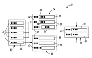
- FIG. 2 is a diagram of a DUN configuration profile that is stored in a memory of the control module illustration in FIG. 1 ;
- FIG. 3 is a flow diagram illustrating a method of setting up the DUN configuration profile to establish a network connection between the control module and the portable electronic device.
- a schematic view of a vehicle is generally indicated by reference number 10 , where an exemplary Dial-Up Networking (DUN) system 20 for establishing a wireless network connection is connected to the vehicle 10 .
- the DUN system 20 includes a personal electronic device 24 , an antenna 26 , a transceiver 28 , a control module 30 , an in-vehicle display 32 and a user input control 34 .
- the antenna 26 , the transceiver 28 , the control module 30 , the in-vehicle display 32 , and the user input control 34 are each integrated or connected with the vehicle 10 , and the personal electronic device 24 is a stand-alone or separate device.
- the portable electronic device 24 is any type of portable electronic device capable of sending and receiving radio frequency (RF) signals from an external RF source 40 .
- the portable electronic device 24 sends and receives RF signals from the external RF source 40 in a form compatible with a wireless cellular network.
- the wireless cellular signals allow for simultaneous use of speech and data services.
- the wireless cellular signals comply with fourth generation wireless standards (4G network), however it is understood that other types of mobile communication frequency signals could be used such as, for example, third generation mobile communication wireless standards.
- 4G network fourth generation wireless standards
- the portable electronic device 24 is a smartphone, however it is understood that other types of portable electronic devices such as, for example, a personal navigation device (PND) may be used as well.
- PND personal navigation device
- the external RF device 40 is any type of structure capable of transmitting and receiving RF signals, and is located in the environment outside of an interior cabin 42 of the vehicle 10 .
- the external RF device is a cellular telephone tower.
- the external RF device 40 is operated by at least one wireless service provider.
- the wireless service provider can be any type of cellular provider that providers speech and data services such as, for example, Verizon Wireless®, T-Mobile®, AT&T® or Sprint®.
- the RF signals sent from the external RF source 40 to the personal electronic device 24 contain information indicating the wireless service provider that is associated with the personal electronic device 24 . For example, if the personal electronic device 24 uses Verizon Wireless® as the wireless service carrier, the RF signal sent from the external RF device 40 to the personal electronic device 24 includes data indicating that Verizon Wireless® is the wireless service provider.
- the personal electronic device 24 further includes circuitry and/or software (not shown) for converting RF signals compatible with a wireless cellular network into RF signals compatible with a short-range wireless network.
- the RF signals compatible with a short-range wireless network can be any type of wireless signal intended for short-range usage such as, for example, a Bluetooth® wireless communication standard based on the IEEE Standard 802.15.
- the personal electronic device 24 is also in bi-directional communication with the antenna 26 of the vehicle 10 .
- the antenna 26 is connected to the transceiver 28 .
- the antenna 26 could be integrated with the transceiver 28 .
- the antenna 26 allows for a data connection to be established between the portable electronic device 24 and the transceiver 28 .
- the transceiver 28 is any device capable of sending and receiving RF signals.
- the transceiver 28 also includes circuitry and/or software for demodulating RF signals into non-modulated signals as well as circuitry and/or software for modulating non-modulated signals into RF signals.
- the antenna 26 allows for the transceiver 28 to transmit and receive RF signals to and from the personal electronic device 24 .
- the antenna 26 is sized to transmit and receive short-range wireless network signals that are emitted from the personal electronic device 24 .
- the transceiver 28 receives the short-range wireless signals from the antenna 26 and demodulates the short-range wireless communication signals into non-modulated signals.
- the transceiver 28 of the vehicle 10 receives data sent by external RF device 40 through the personal electronic device 24 .
- the transceiver 28 is integrated with the control module 30 , however it is understood that the transceiver 28 and the control module 30 may be separate components as well.
- the control module 30 is preferably an electronic control device having a preprogrammed digital computer or processor, control logic, memory used to store data, and at least one I/O peripheral.
- the control logic includes a plurality of logic routines for monitoring, manipulating, and generating data.
- the control module 30 is any type of control module having a memory for storing and supporting a DUN configuration profile such as, for example, an infotainment module, a telematics module or a human machine interface (HMI) module of a vehicle.
- HMI human machine interface
- FIG. 1 illustrates the control module 30 connected to the vehicle 10
- the control module 30 could also be used in a variety of Internet-ready devices as well, such as, for example, an Internet-ready television set.
- the reference number 50 refers to a DUN configuration profile stored in the memory of the control module 30 .
- the DUN configuration profile 50 is used to automatically configure and authenticate the short-range wireless network connection between the control module 30 and the portable electronic device 24 .
- the control module 30 sends and receives non-modulated signals from the transceiver 28 .
- the control module 30 is in communication with the display 32 .
- the display 32 is a screen such as, for example, a liquid crystal display (LCD) that electronically displays graphics such as text, images, and moving pictures.
- the display 32 is located in an area that can be viewed by a driver such as, for example, in the center console (not shown) located within the interior cabin 42 of the vehicle 10 .
- the display 32 is used to show graphical data generated by the control module 30 such as, for example, Internet webpages or moving pictures.
- the display 32 is also in communication with the user input control 34 .
- the user input control 34 is a device for receiving external input from a user, and communicating the external input to the control module 30 .
- the user input control 34 includes tactile controls for a user to manipulate such as, for example, pushbuttons or a keyboard.
- the user input control 34 is a voice-activated system that includes a microphone for detecting a user's voice. The user input control 34 then sends the external input in the form of electronic signals to the control module 30 .
- the control module 30 is in communication with both the display and the user input control 34 .
- the control module 30 includes control logic for converting the electronic signals received from the user input control 34 into graphical data that produces images shown on the display 32 .
- FIG. 2 an illustration of the DUN configuration profile 50 is shown having a first screen 52 , a second screen 54 , a third screen 56 , and a fourth screen 58 .
- a list of possible wireless service carriers 70 are listed on the first screen 52 .
- the DUN configuration profile 50 also includes a plurality of DUN configuration parameters 62 that are listed on the second, third and fourth screens 54 , 56 , 58 .
- a value 64 is associated with each DUN configuration parameter 62 .
- each DUN configuration parameter 62 includes a field 66 , where the value 64 is entered into the field 66 .
- Each value 64 entered into the field 66 of the DUN configuration parameter 62 is used to authenticate the short-range wireless network connection between the portable electronic device 24 and the control module 30 .
- the value 64 of the DUN configuration parameter 62 depends on which wireless service carrier 70 is associated with the portable electronic device 24 .
- the DUN configuration parameters 62 include a User Name, a password, and a Dial Up Number.
- the value 64 for the User Name is based on the assigned user name of the individual associated with the portable electronic device 24 .
- the User Name could also be based on the ten digit telephone number that is associated with the portable electronic device 24 .
- the portable electronic device 24 has a telephone number of 555-555-1212 and a wireless service carrier 70 of Verizon Wireless®, then the User Name would be 5555551212@vzv3g.com.
- the wireless service carrier 70 is Sprint®, and if the assigned user name is john.doe, then the User Name would be john.doe@sprintpcs.com.
- the value 64 for the password is typically a string of characters that depend on the wireless service carrier 70 of the portable electronic device 24 . For example, if Verizon Wireless® is the wireless service carrier 70 of the portable electronic device 24 , then the password would be ‘vzv’.
- the value 64 for the Dial Up Number depends on the wireless service carrier 70 of the portable electronic device 24 . For example, if Verizon Wireless® is the wireless service carrier 70 of the portable electronic device 24 , then the Dial Up Number would be #777.
- the control module 30 (shown in FIG. 1 ) includes control logic for monitoring the transceiver 28 (shown in FIG. 1 ) for non-modulated data signals.
- the control module 30 further includes control logic for determining the wireless service carrier 70 of the portable electronic device 24 .
- the non-modulated data signal received from the transceiver 28 includes data indicating which wireless service carrier 70 is associated with the portable electronic device 24 .
- the control module 30 includes control logic for determining the wireless service carrier associated with the portable electronic device 24 . With this approach, a user does not need to manually select which wireless service carrier 70 is associated with the portable electronic device 24 . However, sometimes the control module 30 is unable to determine the wireless service carrier 70 from the non-modulated signal.
- a user can still manually select which wireless service provider 70 is associated with the portable electronic device 24 .
- a user may manually enter the name of the wireless service carrier 70 using the display 32 and the user input control 34 .
- the display 32 may show the first screen 52 (shown in FIG. 2 ).
- the user may then select the appropriate wireless service carrier 70 by manipulating the user input control 34 .
- a user may have to manually enter all of the values 64 .
- an option 80 labeled “Other” is selected by a user if the wireless service provider is not listed. This selection will then bring up the fourth screen 58 , which allows for a user to manually enter information into the fields 66 .
- the memory of control module 30 stores the specific values 64 of the corresponding DUN configuration parameters 62 for each of the wireless service carriers 70 that are listed on the first screen 52 .
- the memory of the control module 30 would contain data indicating that the ten digit telephone number of the portable electronic device 24 is 555-555-1212.
- the control module 30 further includes control logic for retrieving the value 64 of the DUN configuration parameter from the memory of the control module 30 .
- the control module 30 also includes control logic for entering or populating the value 64 of the DUN configuration parameter 62 into the corresponding field 66 . Specifically, referring to FIG.
- the control logic of the control module 30 enters each of the values 64 into the corresponding field 66 of the DUN configuration parameter 62 . Entering the value 64 into the field 66 of the DUN configuration parameter 62 authenticates the short-range wireless network connection between the control module 30 and the portable electronic device 24 . Thus, a data connection is established between the control module 30 and the portable electronic device 24 .
- the control module 30 may include control logic for generating graphical data that shows at least the first screen 52 of the DUN configuration profile 50 on the display 32 .
- the second and third screens 54 and 56 are not shown on the display 32 , and remain hidden to a user.
- the control module 30 includes control logic for generating graphical data that shows at least one of the second and third screens 54 and 56 on the display 32 .
- only the second screen 54 is shown on the display 32 .
- the control module 30 includes control logic for generating graphical data on the display 32 representative of the second screen 54 .
- the control module 30 also includes control logic for showing a message on the display 32 that indicates whether the values 64 should be confirmed or rejected.
- a user may confirm or reject the values 64 using the user input control 34 .
- only the third screen 56 is shown on the display 32 , where a user confirms their DUN configuration parameters 62 by manually entering the values 64 into the fields 66 .
- DUN configuration parameters 62 for a User Name, Password, and Dial Up Number
- the DUN configuration parameters can be customized or personalized depending on their vehicle identification number (VIN) or the Bluetooth® address.
- the control module 30 of the DUN system 20 includes control logic that automatically enters or populates the fields 66 of the DUN configuration profile 50 .
- a user manually enters the values of the DUN configuration parameters. Some users do not know or believe that it is too time-consuming and tedious to enter all of the DUN configuration parameters. If a user does not enter the correct DUN configuration parameters the short-range wireless network connection can not be established.
- One advantage of the DUN system 20 is that the control module 30 includes an algorithm that automatically establishes the short-range wireless network connection with limited or no input from a user.
- the DUN configuration parameters 62 stored in the memory of the control module 30 can be uploaded and updated periodically during the vehicle's lifecycle to ensure that the DUN configuration parameters 62 are accurate.
- the control module 30 may include control logic for periodically monitoring and updating the DUN configuration parameters 62 if needed.
- the control module 30 obtains the data needed for the update through a wireless data connection such as, for example, the vehicle's OnStar® system.
- a method of authenticating a short-range wireless network using a DUN system 20 is generally indicated by reference number 100 .
- the method 100 begins at step 102 , where a wireless cellular signal is provided.
- the wireless cellular signal is provided by an external RF device 40 , which is illustrated as a cellular telephone tower.
- the external RF device 40 is operated or associated with at least one wireless service provider.
- the method 100 may then proceed to step 104 .
- step 104 the method 100 determines if a portable electronic device 24 is provided, where the portable electronic device 24 receives the wireless cellular signal from the external RF device 40 . If a portable electronic device 24 is not provided, the method 100 remains at step 104 until a portable electronic device 24 is provided at step 105 . Once the portable electronic device 24 is provided and a connection between the external RF device 40 and the portable electronic device 24 is established, the method proceeds to step 106 .
- a control module 30 of the DUN system includes control logic for monitoring a non-modulated data signal emitted from a transceiver 28 .
- the non-modulated data signal includes data indicating the wireless service carrier of the portable electronic device 24 .
- the DUN system 20 includes an antenna 26 that is connected to the transceiver 28 , and the portable electronic device 24 includes circuitry for converting the wireless cellular signal provided by the external RF device 40 into a short-range wireless signal.
- the transceiver 26 receives the short-range wireless signals from the portable electronic device 24 through the antenna 26 and demodulates the short-range wireless communication signals into the non-modulated data signals.
- the control module 30 receives the non-modulated data signal from the transceiver 28 .
- the non-modulated data signal may include data indicating the wireless service carrier that is associated with the portable electronic device 24 .
- Method 100 may then proceed to step 108 .
- the control module 30 determines the wireless service carrier of the portable electronic device 24 .
- the control module 30 includes control logic for determining the wireless service carrier.
- the control module 30 includes control logic for determining the wireless service carrier based on data received from the non-modulated data signal. If the control module 30 successfully determines the wireless service carrier based on the non-modulated data signal, then method 100 proceeds to step 118 . If the control module 30 is unable to determine the wireless service carrier based on the non-modulated signal, then method 100 proceeds to step 110 .
- the control module 30 includes control logic for displaying a list of wireless service carriers on a display 32 .
- a first screen 52 of a DUN configuration profile 50 displays a list of wireless service providers 70 .
- the method 100 determines if the wireless service provider 70 specific to the portable electronic device 24 is shown on the display 32 . If the wireless service provider 70 specific to the portable electronic device 24 is not shown on the display 32 , then method 100 proceeds to step 112 .
- the control module includes control logic for displaying the fourth screen 58 , where fields 66 of the DUN configuration parameters 62 are blank and have no values entered into the fields 66 .
- a user may then manually enter values into the field 66 .
- Method 100 may then proceed to step 126 .
- step 116 a user manually selects the wireless service provider 70 using a user input control 34 .
- Method 100 may then proceed to step 118 .
- the control module 30 includes control logic for selecting one of the values 64 associated with the DUN configuration parameter 62 into the field 66 .
- the memory of control module 30 stores the specific values 64 of the corresponding DUN configuration parameters 62 for each of the wireless service carriers 70 that are listed on the first screen 52 , and the control logic selects one of the values 64 . Selection of the value 64 associated the DUN configuration parameter 62 is dependent on the wireless service carrier. The method 100 may then proceed to step 120 .
- control module 30 includes control logic for entering or populating the value 64 of the DUN configuration parameter 62 into the field 66 .
- Method 100 may then proceed to step 122 .
- the control module 30 includes control logic for generating graphical data that shows the second and third screens 54 and 56 on the display 32 .
- the fields 66 show the values 64 of the DUN configuration parameters 62 that are generated by the control logic of the control module 30 .
- a user is able to view the values 64 on the display 32 .
- Method 100 may then proceed to step 124 .
- control module 30 includes control logic for generating graphical data on the display 32 that indicates whether the values 64 should be confirmed or rejected. A user may confirm or reject the values 64 using the user input control 34 . Method 100 may then proceed to step 126 .
- the control module 30 includes control logic for establishing the short-range wireless network connection between the control module 30 and the portable electronic device 24 . Entering the value 64 into the field 66 of the DUN configuration parameter 62 authenticates the short-range wireless network connection between the control module 30 and the portable electronic device 24 . Once the short-range wireless network connection is established, method 100 may then proceed to step 128 .
- the control module 30 includes control logic for establishing additional DUN configuration parameters.
- DUN configuration parameters 62 for a User Name, Password, and Dial Up Number
- other types of DUN configuration parameters may be used as well to authenticate the short-range wireless network connection between the control module 30 and the portable electronic device 24 .
- the DUN configuration parameters can be customized or personalized depending on such factors such as the vehicle identification number (VIN) or the Bluetooth® address.
- Method 100 may then proceed to step 130 .
- step 130 data is sent over the short-range wireless network connection between the portable electronic device 24 and the control module 30 .
- the short-range wireless network connection provides the control module 30 with Internet access.
- data representative of an Internet webpage could be sent from the external RF device 40 in the form of wireless cellular signals.
- the portable electronic device 24 converts the wireless cellular signals into short-range wireless signals.
- Data is then sent over the short-range wireless network connection from the portable electronic device 24 to the antenna 26 , and to the transceiver 28 .
- the transceiver 28 converts the short-range wireless signals into non-modulated data signals.
- the non-modulated data signals are then sent to the control module 30 .
- the control module 30 includes control logic for converting the non-modulated data signals into data representative of graphical images. This data is sent to the display 32 .
- the Internet webpage is then shown on the display 32 .
- Method 100 may then terminate.
Abstract
Description
Claims (20)
Priority Applications (3)
| Application Number | Priority Date | Filing Date | Title |
|---|---|---|---|
| US12/954,195 US8254840B2 (en) | 2010-11-24 | 2010-11-24 | Auto configuration for a dial-up networking system |
| DE102011119078A DE102011119078A1 (en) | 2010-11-24 | 2011-11-21 | Self-configuration for a dial-up networking system |
| CN201110378002.0A CN102480750B (en) | 2010-11-24 | 2011-11-24 | Dial-up networking system and method for validating dial-up networking system |
Applications Claiming Priority (1)
| Application Number | Priority Date | Filing Date | Title |
|---|---|---|---|
| US12/954,195 US8254840B2 (en) | 2010-11-24 | 2010-11-24 | Auto configuration for a dial-up networking system |
Publications (2)
| Publication Number | Publication Date |
|---|---|
| US20120129494A1 US20120129494A1 (en) | 2012-05-24 |
| US8254840B2 true US8254840B2 (en) | 2012-08-28 |
Family
ID=46021577
Family Applications (1)
| Application Number | Title | Priority Date | Filing Date |
|---|---|---|---|
| US12/954,195 Expired - Fee Related US8254840B2 (en) | 2010-11-24 | 2010-11-24 | Auto configuration for a dial-up networking system |
Country Status (3)
| Country | Link |
|---|---|
| US (1) | US8254840B2 (en) |
| CN (1) | CN102480750B (en) |
| DE (1) | DE102011119078A1 (en) |
Citations (11)
| Publication number | Priority date | Publication date | Assignee | Title |
|---|---|---|---|---|
| US20050048919A1 (en) * | 2003-08-28 | 2005-03-03 | Alcatel | Distributed pairing between different terminals |
| US20050070336A1 (en) * | 2003-09-30 | 2005-03-31 | Kabushiki Kaisha Toshiba | Method for communication control and wireless communication system |
| US7389334B2 (en) * | 2000-04-24 | 2008-06-17 | Microsoft Corporation | Exposing bluetooth compliant wireless device connection as modems or sockets |
| US7463861B2 (en) * | 2005-03-07 | 2008-12-09 | Broadcom Corporation | Automatic data encryption and access control based on bluetooth device proximity |
| US20090075697A1 (en) * | 2007-09-13 | 2009-03-19 | Research In Motion Limited | System and method for interfacing between a mobile device and a personal computer |
| US7551593B2 (en) * | 2001-11-21 | 2009-06-23 | Ixi Mobile (R&D), Ltd. | Device, system, method and computer readable medium for pairing of devices in a short distance wireless network |
| US20100216401A1 (en) * | 2009-02-23 | 2010-08-26 | Fujitsu Ten Limited | In-vehicle device and communication control method |
| US7796572B2 (en) * | 2003-04-29 | 2010-09-14 | Telenor Asa | Virtual device |
| US7925212B2 (en) * | 2005-03-07 | 2011-04-12 | Broadcom Corporation | Automatic network and device configuration for handheld devices based on bluetooth device proximity |
| US7979028B2 (en) * | 2004-10-21 | 2011-07-12 | Denso Corporation | Bluetooth communicator, short range wireless communicator and communication method |
| US8112037B2 (en) * | 2008-09-02 | 2012-02-07 | Nissaf Ketari | Bluetooth assistant |
Family Cites Families (3)
| Publication number | Priority date | Publication date | Assignee | Title |
|---|---|---|---|---|
| FI111494B (en) * | 2001-06-29 | 2003-07-31 | Nokia Corp | Wireless interface extension |
| US9084282B2 (en) * | 2008-10-17 | 2015-07-14 | Qualcomm Incorporated | Apparatus and method for providing a portable broadband service using a wireless convergence platform |
| CN101702836A (en) * | 2009-11-17 | 2010-05-05 | 中兴通讯股份有限公司 | Method and device for establishing dial-up service |
-
2010
- 2010-11-24 US US12/954,195 patent/US8254840B2/en not_active Expired - Fee Related
-
2011
- 2011-11-21 DE DE102011119078A patent/DE102011119078A1/en not_active Withdrawn
- 2011-11-24 CN CN201110378002.0A patent/CN102480750B/en not_active Expired - Fee Related
Patent Citations (11)
| Publication number | Priority date | Publication date | Assignee | Title |
|---|---|---|---|---|
| US7389334B2 (en) * | 2000-04-24 | 2008-06-17 | Microsoft Corporation | Exposing bluetooth compliant wireless device connection as modems or sockets |
| US7551593B2 (en) * | 2001-11-21 | 2009-06-23 | Ixi Mobile (R&D), Ltd. | Device, system, method and computer readable medium for pairing of devices in a short distance wireless network |
| US7796572B2 (en) * | 2003-04-29 | 2010-09-14 | Telenor Asa | Virtual device |
| US20050048919A1 (en) * | 2003-08-28 | 2005-03-03 | Alcatel | Distributed pairing between different terminals |
| US20050070336A1 (en) * | 2003-09-30 | 2005-03-31 | Kabushiki Kaisha Toshiba | Method for communication control and wireless communication system |
| US7979028B2 (en) * | 2004-10-21 | 2011-07-12 | Denso Corporation | Bluetooth communicator, short range wireless communicator and communication method |
| US7463861B2 (en) * | 2005-03-07 | 2008-12-09 | Broadcom Corporation | Automatic data encryption and access control based on bluetooth device proximity |
| US7925212B2 (en) * | 2005-03-07 | 2011-04-12 | Broadcom Corporation | Automatic network and device configuration for handheld devices based on bluetooth device proximity |
| US20090075697A1 (en) * | 2007-09-13 | 2009-03-19 | Research In Motion Limited | System and method for interfacing between a mobile device and a personal computer |
| US8112037B2 (en) * | 2008-09-02 | 2012-02-07 | Nissaf Ketari | Bluetooth assistant |
| US20100216401A1 (en) * | 2009-02-23 | 2010-08-26 | Fujitsu Ten Limited | In-vehicle device and communication control method |
Non-Patent Citations (1)
| Title |
|---|
| TREO 650 smartphone. Using Dial-up Networking, user's manual, by palmOne, 2004. * |
Also Published As
| Publication number | Publication date |
|---|---|
| CN102480750B (en) | 2015-04-01 |
| US20120129494A1 (en) | 2012-05-24 |
| DE102011119078A1 (en) | 2012-05-24 |
| CN102480750A (en) | 2012-05-30 |
Similar Documents
| Publication | Publication Date | Title |
|---|---|---|
| US10159098B2 (en) | Efficient headunit communication integration | |
| US8660549B2 (en) | Avoiding battery depletion of a mobile device | |
| US20110045842A1 (en) | Method and System For Updating A Social Networking System Based On Vehicle Events | |
| US20150224876A1 (en) | Mobile terminal device, on-vehicle device, and on-vehicle system | |
| US9576474B2 (en) | Providing cellular data to a vehicle over different data channels | |
| US9467179B2 (en) | Vehicle head unit priority | |
| CN107925866B (en) | System and method for contacting occupants of remote vehicles using DSRC | |
| US8874163B2 (en) | Method and apparatus for managing sound volume of wireless connection device in mobile communication terminal | |
| CN107666698A (en) | Automobile wireless access point is operated to be selectively connected to wireless vehicle device | |
| US9560470B2 (en) | Updating a vehicle head unit with content from a wireless device | |
| KR20130113283A (en) | Acquiring method vehicle contents, displaying method vehicle contents, displaying system for vehicle contents and automotive electronic device | |
| US20180043903A1 (en) | Wirelessly communicating user-controlled vehicle preference settings with a remote location | |
| KR100830303B1 (en) | Portable terminal device, site access method using thereof and computer readable medium | |
| JP5726008B2 (en) | Display control apparatus and display control method for connected device list | |
| KR101427717B1 (en) | Taxi call service system using display communicating with smart mobile device and method using these | |
| US11093202B2 (en) | Method and apparatus for dual display and dual SIM operations | |
| US20150365519A1 (en) | Providing tty services in a vehicle | |
| US8254840B2 (en) | Auto configuration for a dial-up networking system | |
| KR101438835B1 (en) | Method for using phonebook in vehicle | |
| KR101525704B1 (en) | Apparatus for vehicle cluster controlling with smartphone linkage | |
| US10104602B2 (en) | Coordination of cellular data through a selected cellular device | |
| KR20080082194A (en) | Car navigation system, upgrade terminal, upgrade system and a control method thereof | |
| JP5896451B2 (en) | In-vehicle communication device, communication system, communication method, and program | |
| KR100871117B1 (en) | Position information providing system and mehtod using sms | |
| KR100724639B1 (en) | Digital multimedia broadcasting receiver having location registration and notification function and registration and notification method using the same |
Legal Events
| Date | Code | Title | Description |
|---|---|---|---|
| AS | Assignment |
Owner name: GM GLOBAL TECHNOLOGY OPERATIONS, INC., MICHIGAN Free format text: ASSIGNMENT OF ASSIGNORS INTEREST;ASSIGNORS:QUINN, MICHAEL J.;POP, DAVID P.;LOBAZA, ANTHONY G.;REEL/FRAME:025427/0495 Effective date: 20101108 |
|
| AS | Assignment |
Owner name: GM GLOBAL TECHNOLOGY OPERATIONS LLC, MICHIGAN Free format text: CHANGE OF NAME;ASSIGNOR:GM GLOBAL TECHNOLOGY OPERATIONS, INC.;REEL/FRAME:025780/0482 Effective date: 20101202 |
|
| AS | Assignment |
Owner name: WILMINGTON TRUST COMPANY, DELAWARE Free format text: SECURITY AGREEMENT;ASSIGNOR:GM GLOBAL TECHNOLOGY OPERATIONS LLC;REEL/FRAME:026499/0267 Effective date: 20101027 |
|
| FEPP | Fee payment procedure |
Free format text: PAYOR NUMBER ASSIGNED (ORIGINAL EVENT CODE: ASPN); ENTITY STATUS OF PATENT OWNER: LARGE ENTITY |
|
| STCF | Information on status: patent grant |
Free format text: PATENTED CASE |
|
| AS | Assignment |
Owner name: GM GLOBAL TECHNOLOGY OPERATIONS LLC, MICHIGAN Free format text: RELEASE BY SECURED PARTY;ASSIGNOR:WILMINGTON TRUST COMPANY;REEL/FRAME:034287/0159 Effective date: 20141017 |
|
| FPAY | Fee payment |
Year of fee payment: 4 |
|
| FEPP | Fee payment procedure |
Free format text: MAINTENANCE FEE REMINDER MAILED (ORIGINAL EVENT CODE: REM.); ENTITY STATUS OF PATENT OWNER: LARGE ENTITY |
|
| LAPS | Lapse for failure to pay maintenance fees |
Free format text: PATENT EXPIRED FOR FAILURE TO PAY MAINTENANCE FEES (ORIGINAL EVENT CODE: EXP.); ENTITY STATUS OF PATENT OWNER: LARGE ENTITY |
|
| STCH | Information on status: patent discontinuation |
Free format text: PATENT EXPIRED DUE TO NONPAYMENT OF MAINTENANCE FEES UNDER 37 CFR 1.362 |
|
| FP | Lapsed due to failure to pay maintenance fee |
Effective date: 20200828 |