US8499874B2 - Gas turbine energy storage and conversion system - Google Patents
Gas turbine energy storage and conversion system Download PDFInfo
- Publication number
- US8499874B2 US8499874B2 US12/777,916 US77791610A US8499874B2 US 8499874 B2 US8499874 B2 US 8499874B2 US 77791610 A US77791610 A US 77791610A US 8499874 B2 US8499874 B2 US 8499874B2
- Authority
- US
- United States
- Prior art keywords
- working fluid
- energy
- pressurized working
- thermal
- combustor
- Prior art date
- Legal status (The legal status is an assumption and is not a legal conclusion. Google has not performed a legal analysis and makes no representation as to the accuracy of the status listed.)
- Active, expires
Links
Images


Classifications
-
- F—MECHANICAL ENGINEERING; LIGHTING; HEATING; WEAPONS; BLASTING
- F01—MACHINES OR ENGINES IN GENERAL; ENGINE PLANTS IN GENERAL; STEAM ENGINES
- F01D—NON-POSITIVE DISPLACEMENT MACHINES OR ENGINES, e.g. STEAM TURBINES
- F01D25/00—Component parts, details, or accessories, not provided for in, or of interest apart from, other groups
- F01D25/08—Cooling; Heating; Heat-insulation
- F01D25/10—Heating, e.g. warming-up before starting
-
- B—PERFORMING OPERATIONS; TRANSPORTING
- B60—VEHICLES IN GENERAL
- B60K—ARRANGEMENT OR MOUNTING OF PROPULSION UNITS OR OF TRANSMISSIONS IN VEHICLES; ARRANGEMENT OR MOUNTING OF PLURAL DIVERSE PRIME-MOVERS IN VEHICLES; AUXILIARY DRIVES FOR VEHICLES; INSTRUMENTATION OR DASHBOARDS FOR VEHICLES; ARRANGEMENTS IN CONNECTION WITH COOLING, AIR INTAKE, GAS EXHAUST OR FUEL SUPPLY OF PROPULSION UNITS IN VEHICLES
- B60K3/00—Arrangement or mounting of steam or gaseous-pressure propulsion units
- B60K3/04—Arrangement or mounting of steam or gaseous-pressure propulsion units of turbine type
-
- B—PERFORMING OPERATIONS; TRANSPORTING
- B60—VEHICLES IN GENERAL
- B60K—ARRANGEMENT OR MOUNTING OF PROPULSION UNITS OR OF TRANSMISSIONS IN VEHICLES; ARRANGEMENT OR MOUNTING OF PLURAL DIVERSE PRIME-MOVERS IN VEHICLES; AUXILIARY DRIVES FOR VEHICLES; INSTRUMENTATION OR DASHBOARDS FOR VEHICLES; ARRANGEMENTS IN CONNECTION WITH COOLING, AIR INTAKE, GAS EXHAUST OR FUEL SUPPLY OF PROPULSION UNITS IN VEHICLES
- B60K6/00—Arrangement or mounting of plural diverse prime-movers for mutual or common propulsion, e.g. hybrid propulsion systems comprising electric motors and internal combustion engines ; Control systems therefor, i.e. systems controlling two or more prime movers, or controlling one of these prime movers and any of the transmission, drive or drive units Informative references: mechanical gearings with secondary electric drive F16H3/72; arrangements for handling mechanical energy structurally associated with the dynamo-electric machine H02K7/00; machines comprising structurally interrelated motor and generator parts H02K51/00; dynamo-electric machines not otherwise provided for in H02K see H02K99/00
- B60K6/08—Prime-movers comprising combustion engines and mechanical or fluid energy storing means
- B60K6/12—Prime-movers comprising combustion engines and mechanical or fluid energy storing means by means of a chargeable fluidic accumulator
-
- F—MECHANICAL ENGINEERING; LIGHTING; HEATING; WEAPONS; BLASTING
- F01—MACHINES OR ENGINES IN GENERAL; ENGINE PLANTS IN GENERAL; STEAM ENGINES
- F01K—STEAM ENGINE PLANTS; STEAM ACCUMULATORS; ENGINE PLANTS NOT OTHERWISE PROVIDED FOR; ENGINES USING SPECIAL WORKING FLUIDS OR CYCLES
- F01K15/00—Adaptations of plants for special use
- F01K15/02—Adaptations of plants for special use for driving vehicles, e.g. locomotives
-
- F—MECHANICAL ENGINEERING; LIGHTING; HEATING; WEAPONS; BLASTING
- F01—MACHINES OR ENGINES IN GENERAL; ENGINE PLANTS IN GENERAL; STEAM ENGINES
- F01K—STEAM ENGINE PLANTS; STEAM ACCUMULATORS; ENGINE PLANTS NOT OTHERWISE PROVIDED FOR; ENGINES USING SPECIAL WORKING FLUIDS OR CYCLES
- F01K3/00—Plants characterised by the use of steam or heat accumulators, or intermediate steam heaters, therein
- F01K3/02—Use of accumulators and specific engine types; Control thereof
-
- F—MECHANICAL ENGINEERING; LIGHTING; HEATING; WEAPONS; BLASTING
- F02—COMBUSTION ENGINES; HOT-GAS OR COMBUSTION-PRODUCT ENGINE PLANTS
- F02C—GAS-TURBINE PLANTS; AIR INTAKES FOR JET-PROPULSION PLANTS; CONTROLLING FUEL SUPPLY IN AIR-BREATHING JET-PROPULSION PLANTS
- F02C1/00—Gas-turbine plants characterised by the use of hot gases or unheated pressurised gases, as the working fluid
- F02C1/04—Gas-turbine plants characterised by the use of hot gases or unheated pressurised gases, as the working fluid the working fluid being heated indirectly
- F02C1/05—Gas-turbine plants characterised by the use of hot gases or unheated pressurised gases, as the working fluid the working fluid being heated indirectly characterised by the type or source of heat, e.g. using nuclear or solar energy
-
- F—MECHANICAL ENGINEERING; LIGHTING; HEATING; WEAPONS; BLASTING
- F02—COMBUSTION ENGINES; HOT-GAS OR COMBUSTION-PRODUCT ENGINE PLANTS
- F02C—GAS-TURBINE PLANTS; AIR INTAKES FOR JET-PROPULSION PLANTS; CONTROLLING FUEL SUPPLY IN AIR-BREATHING JET-PROPULSION PLANTS
- F02C6/00—Plural gas-turbine plants; Combinations of gas-turbine plants with other apparatus; Adaptations of gas- turbine plants for special use
- F02C6/14—Gas-turbine plants having means for storing energy, e.g. for meeting peak loads
- F02C6/16—Gas-turbine plants having means for storing energy, e.g. for meeting peak loads for storing compressed air
-
- B—PERFORMING OPERATIONS; TRANSPORTING
- B60—VEHICLES IN GENERAL
- B60K—ARRANGEMENT OR MOUNTING OF PROPULSION UNITS OR OF TRANSMISSIONS IN VEHICLES; ARRANGEMENT OR MOUNTING OF PLURAL DIVERSE PRIME-MOVERS IN VEHICLES; AUXILIARY DRIVES FOR VEHICLES; INSTRUMENTATION OR DASHBOARDS FOR VEHICLES; ARRANGEMENTS IN CONNECTION WITH COOLING, AIR INTAKE, GAS EXHAUST OR FUEL SUPPLY OF PROPULSION UNITS IN VEHICLES
- B60K1/00—Arrangement or mounting of electrical propulsion units
-
- B—PERFORMING OPERATIONS; TRANSPORTING
- B60—VEHICLES IN GENERAL
- B60W—CONJOINT CONTROL OF VEHICLE SUB-UNITS OF DIFFERENT TYPE OR DIFFERENT FUNCTION; CONTROL SYSTEMS SPECIALLY ADAPTED FOR HYBRID VEHICLES; ROAD VEHICLE DRIVE CONTROL SYSTEMS FOR PURPOSES NOT RELATED TO THE CONTROL OF A PARTICULAR SUB-UNIT
- B60W2710/00—Output or target parameters relating to a particular sub-units
- B60W2710/06—Combustion engines, Gas turbines
-
- B—PERFORMING OPERATIONS; TRANSPORTING
- B60—VEHICLES IN GENERAL
- B60Y—INDEXING SCHEME RELATING TO ASPECTS CROSS-CUTTING VEHICLE TECHNOLOGY
- B60Y2400/00—Special features of vehicle units
- B60Y2400/15—Pneumatic energy storages, e.g. pressure air tanks
-
- F—MECHANICAL ENGINEERING; LIGHTING; HEATING; WEAPONS; BLASTING
- F05—INDEXING SCHEMES RELATING TO ENGINES OR PUMPS IN VARIOUS SUBCLASSES OF CLASSES F01-F04
- F05D—INDEXING SCHEME FOR ASPECTS RELATING TO NON-POSITIVE-DISPLACEMENT MACHINES OR ENGINES, GAS-TURBINES OR JET-PROPULSION PLANTS
- F05D2220/00—Application
- F05D2220/60—Application making use of surplus or waste energy
- F05D2220/62—Application making use of surplus or waste energy with energy recovery turbines
-
- F—MECHANICAL ENGINEERING; LIGHTING; HEATING; WEAPONS; BLASTING
- F05—INDEXING SCHEMES RELATING TO ENGINES OR PUMPS IN VARIOUS SUBCLASSES OF CLASSES F01-F04
- F05D—INDEXING SCHEME FOR ASPECTS RELATING TO NON-POSITIVE-DISPLACEMENT MACHINES OR ENGINES, GAS-TURBINES OR JET-PROPULSION PLANTS
- F05D2260/00—Function
- F05D2260/90—Braking
-
- Y—GENERAL TAGGING OF NEW TECHNOLOGICAL DEVELOPMENTS; GENERAL TAGGING OF CROSS-SECTIONAL TECHNOLOGIES SPANNING OVER SEVERAL SECTIONS OF THE IPC; TECHNICAL SUBJECTS COVERED BY FORMER USPC CROSS-REFERENCE ART COLLECTIONS [XRACs] AND DIGESTS
- Y02—TECHNOLOGIES OR APPLICATIONS FOR MITIGATION OR ADAPTATION AGAINST CLIMATE CHANGE
- Y02E—REDUCTION OF GREENHOUSE GAS [GHG] EMISSIONS, RELATED TO ENERGY GENERATION, TRANSMISSION OR DISTRIBUTION
- Y02E60/00—Enabling technologies; Technologies with a potential or indirect contribution to GHG emissions mitigation
- Y02E60/16—Mechanical energy storage, e.g. flywheels or pressurised fluids
-
- Y—GENERAL TAGGING OF NEW TECHNOLOGICAL DEVELOPMENTS; GENERAL TAGGING OF CROSS-SECTIONAL TECHNOLOGIES SPANNING OVER SEVERAL SECTIONS OF THE IPC; TECHNICAL SUBJECTS COVERED BY FORMER USPC CROSS-REFERENCE ART COLLECTIONS [XRACs] AND DIGESTS
- Y02—TECHNOLOGIES OR APPLICATIONS FOR MITIGATION OR ADAPTATION AGAINST CLIMATE CHANGE
- Y02T—CLIMATE CHANGE MITIGATION TECHNOLOGIES RELATED TO TRANSPORTATION
- Y02T10/00—Road transport of goods or passengers
- Y02T10/60—Other road transportation technologies with climate change mitigation effect
- Y02T10/62—Hybrid vehicles
Definitions
- the present invention relates generally to the field of regenerative braking and energy storage in gas turbine engines.
- the gas turbine or Brayton cycle power plant has demonstrated many attractive features which make it a candidate for advanced vehicular propulsion.
- the gas turbine does not allow the normal “engine braking” or “compression braking” feature that is extensively used in piston-type engines.
- many modern regenerative braking systems rely on batteries or other electrical storage subsystems to receive and absorb excess braking energy (others utilize pneumatic or hydraulic storage). In most cases, the cost of this energy storage is significant. Sizing a typical battery or ultra-capacitor energy storage system to absorb energy at high power associated with a long down-hill decent, for example, is prohibitively expensive.
- Gas turbine engines have the additional advantage of being highly fuel flexible and fuel tolerant.
- gas turbines can be operated on a variety of fuels such as diesel, gasoline, ethanol, methanol, natural gas, biofuels and hydrogen.
- the performance of gas turbine engines can be improved by making use of electrical energy recovered by a regenerative braking system. These improvements may include extending component lifetimes, pre-heating of fuels and providing an engine braking capability analogous to the Jacobs brake used by piston engines.
- the present invention is directed to a gas turbine engine that uses high temperature materials such as ceramic and/or metallic elements to store heat energy derived from a regenerative braking capability.
- the embodiment combines the principles of a gas turbine or Brayton cycle engine with an electric or hybrid transmission system. New techniques of thermal energy storage and thermal energy manipulation that can recover substantial amounts of energy normally discarded in braking are disclosed.
- a method that includes the steps of:
- a turbine power plant that includes:
- a turbine power plant that includes:
- a vehicle in another configuration, includes:
- a vehicle in another configuration, includes:
- gas turbines to vehicular propulsion demands a wide range of power production from the engine. Further, improved driving economies are derived from recovering energy normally lost in braking. In some cases, associated with long down-hill decent, the engine can be configured to absorb considerable energy, so as to prevent the excessive load on other braking systems.
- An electric drive-train uses electric traction motors to drive the wheels. During braking the flow of power reverses as the wheels drive the traction motors, thereby generating electricity derived from the energy of braking (referred to commonly as regenerative braking).
- This principal is prior art and may be incorporated into a vehicle with either an Otto cycle, Diesel cycle, Brayton (gas turbine) cycle, or any propulsion power plant.
- Embodiments of the subject invention use this regenerated electricity in a manner that provides economic advantages over normal battery or other electrical storage methods, which are typically charge-rate and capacity limited.
- Embodiments of the present invention are referred to herein as thermal energy storage modules and incorporate one or more electric resistor/heat storage elements located within the engine's fluid conduit and pressure boundary to absorb over-flow braking energy from an electrical generator that is typically part of an electric or hybrid transmission.
- the electric resistor element converts electrical energy by resistive or Joule heating and delivers thermal energy to gas turbine's air flow during normal driving.
- These electric resistor elements may be located, for example, upstream of combustor, in the combustor, upstream of the free power turbine, upstream of the hot side of a recuperator, or any combination of these locations. Residual thermal energy remaining after braking or stopping may be used to assist combustor relight or ignition.
- each of the expressions “at least one of A, B and C”, “at least one of A, B, or C”, “one or more of A, B, and C”, “one or more of A, B, or C” and “A, B, and/or C” means A alone, B alone, C alone, A and B together, A and C together, B and C together, or A, B and C together.
- Dynamic braking is implemented when the electric propulsion motors are switched to generator mode during braking to augment the braking force.
- the electrical energy generated is typically dissipated in a resistance grid system. If the electrical energy generated is recaptured and stored in an electrical energy storage system, dynamic braking is then typically referred to as regenerative braking.
- An energy storage system refers to any apparatus that acquires, stores and distributes mechanical, electrical or thermal energy which is produced from another energy source such as a prime energy source, a regenerative braking system, a third rail and a catenary and any external source of electrical energy. Examples are a heat block, a battery pack, a bank of capacitors, a compressed air storage system and a bank of flywheels or a combination of storage systems.
- An engine refers to any device that uses energy to develop mechanical power, such as motion in some other machine. Examples are diesel engines, gas turbine engines, microturbines, Stirling engines and spark ignition engines.
- a gear box as used herein is a housing that includes at least one gear set.
- a gear set as used herein is a single ratio gear assembly.
- a heat block is a solid volume of material with a high heat capacity and high melting temperature to which heat can be added by electrical resistive or inductive heating and from which heat can be extracted by heat transfer to a fluid.
- a hybrid vehicle combines an energy storage system, a prime power unit, and a vehicle propulsion system.
- a parallel hybrid vehicle is configured so that propulsive power can be provided by the prime power source only, the energy storage source only, or both.
- propulsive power is provided by the energy storage unit only and the prime power source is used to supply energy to the energy storage unit.
- the hybrid may be referred to as a power-assist hybrid.
- an electric drive may be used primarily for starting and power assist while an internal combustion engine used primarily for propulsion.
- These vehicles are typically parallel hybrids.
- the energy storage and prime power are approximately balanced.
- a dual-mode hybrid can operate on electric drive only, on engine power only, or on a combination of both. These vehicles are typically parallel hybrids.
- Jake brake or Jacobs brake describes a particular brand of engine braking system. It is used generically to refer to engine brakes or compression release engine brakes in general, especially on large vehicles or heavy equipment.
- An engine brake is a braking system used primarily on semi-trucks or other large vehicles that modifies engine valve operation to use engine compression to slow the vehicle. They are also known as compression release engine brakes.
- a mechanical-to-electrical energy conversion device refers to an apparatus that converts mechanical energy to electrical energy or electrical energy to mechanical energy. Examples include but are not limited to a synchronous alternator such as a wound rotor alternator or a permanent magnet machine, an asynchronous alternator such as an induction alternator, a DC generator, and a switched reluctance generator.
- a traction motor is a mechanical-to-electrical energy conversion device used primarily for propulsion.
- Module as used herein in conjunction with a computer refers to any known or later developed hardware, software, firmware, artificial intelligence, fuzzy logic, or combination of hardware and software that is capable of performing the functionality associated with that element. Also, while the invention is described in terms of exemplary embodiments, it should be appreciated that individual aspects of the invention can be separately claimed.
- a permanent magnet motor is a synchronous rotating electric machine where the stator is a three phase stator like that of an induction motor and the rotor has surface-mounted permanent magnets.
- the permanent magnet synchronous motor is equivalent to an induction motor where the air gap magnetic field is produced by a permanent magnet.
- the use of a permanent magnet to generate a substantial air gap magnetic flux makes it possible to design highly efficient motors.
- a standard 3-phase permanent magnet synchronous motor a standard 3-phase power stage is used. The power stage utilizes six power transistors with independent switching. The power transistors are switched in ways to allow the motor to generate power, to be free-wheeling or to act as a generator by controlling pulse frequency or pulse width.
- a prime power source refers to any device that uses energy to develop mechanical or electrical power, such as motion in some other machine. Examples are diesel engines, gas turbine engines, microturbines, Stirling engines, spark ignition engines and fuel cells.
- Power density as used herein is power per unit volume (watts per cubic meter).
- a range-extended hybrid has a large energy storage capacity and a small prime power source.
- An example would be an electric drive vehicle with a small engine used for charging an electrical energy storage unit. These vehicles are typically series hybrids.
- a recuperator is a heat exchanger that transfers heat through a network of tubes, a network of ducts or walls of a matrix wherein the flow on the hot side of the heat exchanger is typically exhaust gas and the flow on cold side of the heat exchanger is typically a gas such as air entering the combustion chamber. The flow of heat is from the hot side of the recuperator to the cold side of the recuperator.
- Regenerative braking is the same as dynamic braking except the electrical energy generated is recaptured and stored in an energy storage system for future use.
- Specific power as used herein is power per unit mass (watts per kilogram).
- Spool means a group of turbo machinery components on a common shaft.
- a thermal energy storage module is a device that includes either a metallic heat storage element or a ceramic heat storage element with embedded electrically conductive wires.
- a thermal energy storage module is similar to a heat storage block but is typically smaller in size and energy storage capacity.
- a traction motor is a motor used primarily for propulsion such as commonly used in a locomotive. Examples are an AC or DC induction motor, a permanent magnet motor and a switched reluctance motor.
- a turbine is any machine in which mechanical work is extracted from a moving fluid by expanding the fluid from a higher pressure to a lower pressure.
- a vehicle is any device, apparatus or system for carrying, conveying, or otherwise transporting animate and/or inanimate objects, such as persons, including without limitation land conveyances (such as cars, trucks, buses, trains, and the like), maritime and other types of water vessels (such as ships, boats, and other watercraft), and aircraft.
- land conveyances such as cars, trucks, buses, trains, and the like
- maritime and other types of water vessels such as ships, boats, and other watercraft
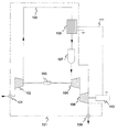
- FIG. 1 is a schematic of a simple cycle gas turbine with electrically heated resistor bank integrated within the engine conduit.
- FIG. 2 is a schematic of an intercooled recuperated gas turbine with bypass around recuperator to increase thermal capacity of resistively heated thermal storage.
- FIG. 3 is a schematic of an intercooled recuperated gas turbine cycle with reheat.
- FIG. 4 is a schematic of an electric transmission suitable for regenerative braking with a gas turbine engine.
- FIG. 5 is a schematic of an alternate electric transmission suitable for regenerative braking with a gas turbine engine.
- FIG. 6 a is a sectional view of an electrically heated thermal energy storage module representation.
- FIG. 6 b is a first sectional view of the energy storage module representation taken along line A-A of FIG. 6 a.
- FIG. 6 c is a second sectional view of the energy storage module representation taken along line A-A of FIG. 6 a.
- FIG. 7 is a schematic of an electrically heated thermal storage module representation with surface combustion thermal reactor.
- FIG. 8 is an isometric view of a first configuration of a thermal energy storage module.
- FIG. 9 a shows an end view of the thermal energy storage module of FIG. 8 .
- FIG. 9 b is a sectional view along line A-A of FIG. 9 a of the thermal energy storage module representation of FIG. 8 .
- FIG. 9 c is an end view of the energy storage module representation of FIG. 8 .
- FIG. 10 is an isometric view of a second configuration of a thermal energy storage module.
- FIG. 11 a shows an end view of the thermal energy storage module of FIG. 10 .
- FIG. 11 b is a sectional view along A-A of FIG. 11 a of the thermal energy storage module representation of FIG. 10 .
- FIG. 11 c is an end view of the energy storage module representation of FIG. 10 .
- FIG. 12 is an isometric view of a third configuration of a thermal energy storage module.
- FIG. 13 shows an end view of the thermal energy storage module of FIG. 12 .
- FIG. 13 b is a sectional view along line A-A of FIG. 13 a of the thermal energy storage module representation of FIG. 13 a .
- FIG. 14 is a schematic of a regenerative braking energy distribution control system for a gas turbine with at least one thermal energy storage module.
- Heat energy storage technology is known. For example, this technology has been proposed for non-nuclear submarines allowing them to operate for several hours to days while underwater.
- One of these technologies is the use of a graphite heat block as a heat source for a closed-cycle gas turbine power plant.
- a graphite block heated to 2,750 K in an induction furnace to provide energy in place of a combustor has been disclosed.
- An inert gas flows through the block, picks up heat, spins the turbine and returns to complete the loop.
- the energy storage possible with this technology is substantially higher than other forms of energy storage and, in particular, is compatible with gas turbines as a source of supplementary energy derived, for example, from regenerative braking.
- Capacitors, inductors, some batteries and flywheels can release their energy at very high rates but typically at the expense of energy storage capacity.
- Graphite at high temperatures has a specific energy capacity comparable to chemical explosives and is a very compact form of energy storage compared to capacitors, inductors, flywheels and batteries commonly used in regenerative braking energy storage systems. Typical specific energy capacities associated with several energy storage technologies are shown in Table 1 below.
- the properties of carbon and other materials such as ceramics make them useful for the collection and storage of thermal energy. These properties include: (1) a high heat capacity, especially at elevated temperatures; (2) a high melting point; and (3) a high thermal conductivity.
- Preferred heat storage materials for example, have a density of at least about 1,800 kg/m 3 , even more preferably of at least about 3,500 kg/m 3 , and even more preferably ranging from about 1,800 to about 7,500 kg/m 3 ; and a heat capacity of at least about 400 J/kg-K, even more preferably of at least about 700 J/kg-K, and even more preferably ranging from about 400 to about 1,700 J/kg-K.
- the material should provide a high heat transfer efficiency.
- the ratio of the thermal power transferred to the working fluid to the electrical power generated by regenerative braking is at least about 0.20 and even more preferably ranges from about 0.30 to about 0.70.
- This ratio is a function of working fluid flow velocity and density, surface area of the material, its thermal conductivity and its electrical resistivity
- the material preferably has a thermal conductivity of at least about 5 W/m-K, more preferably of at least about 10 W/m-K, and even more preferably of at least about 20 W/m-K.
- a preferred heat storage material also has a melting temperature in excess of the maximum temperature in the combustor (usually the combustor outlet temperature), even more preferably at least about 120% of the maximum temperature in the combustor, and even more preferably at least about 150% of the maximum temperature in the combustor.
- a number of suitable materials such as graphite, boron nitride, boron carbide, silicon carbide, silicon dioxide, magnesium oxide, tungsten carbide and alumina can be used for heat storage.
- suitable materials such as graphite, boron nitride, boron carbide, silicon carbide, silicon dioxide, magnesium oxide, tungsten carbide and alumina.
- High working temperature metals are required for electrical conduits embedded in ceramics and other non-conducting heat storage materials.
- Such electrical conductors may be formed from tungsten wire, for example.
- Kanthal A1 is a preferable choice.
- the material when the heat storage material also converts electrical energy into thermal energy (for example, Kanthal or Inconel alloys), the material should have an appropriate electrical resistivity.
- the electrical resistivity is at least about 0.1 ⁇ 10 ⁇ 6 ohm-meters, even more preferably at least about 0.5 ⁇ 10 ⁇ 6 ohm-meters.
- Kanthal A1 and Kanthal APM are density of about 7,100 kg/cu m, heat capacity of about 460 J/kg-K, thermal conductivity of about 13 W/m-K.
- the practical maximum continuous operating temperature for Kanthal A1 (and Kanthal AF) is about 1,670 K.
- a Kanthal heat storage module of the present invention would be cycled between a low temperature of about 780 K (discharged) up to a fully charged temperature for short periods of about 1,700 K.
- the present invention integrates one or more electrical resistance heater elements into the gas turbine engine, receiving the regenerated electrical power and converting it to thermal storage and then to energy of the gas turbine's working fluid.
- the electrical heater is located within the engine's fluid conduit and pressure boundary, thereby eliminating the need for secondary transport fluids and facilitating the transport of the power through the engine's structural casing.
- FIG. 1 is a schematic representation of this basic principal for a single stage gas turbine engine.
- Compressor 102 pressurizes the engine working fluid, typically air or a lean air-fuel mixture.
- Conduit 105 is employed to transport the fluid to an electrically heated thermal storage module 106 , combustor 109 and turbine 104 .
- conduits such as conduit 105 , connecting the various components are denoted by solid lines.
- a free power turbine 108 is connected to a drive train 110 which includes gear assemblies, electrical generator/motors, drive shafts, differentials and axles.
- Drive train 110 transmits mechanical or electrical propulsion power while motoring and generates electrical power while braking. Examples of these drive trains configured as electrical transmissions are described in FIGS. 4 and 5 .
- the electrical power generated within drive train 110 while braking is carried by conductor 111 (denoted by dashed lines) and passes through pressure boundary 131 (denoted by dot-dash lines) using a low resistance connector, well-known as an electrical feed-through.
- the electrical current causes Joule heating to occur in resistive element 106 .
- This resistive heating element 106 may be fabricated from metallic wire or ceramic materials in which conductive wires are embedded. The temperature of heating element 106 will rise as electrical energy is delivered and absorbed. During periods of power demand from the engine, the absorbed thermal energy is convected to the gas turbine working fluid to offset energy that would otherwise be required from the fuel burned in the down-stream combustor 109 .
- the electrical power is delivered to the resistively heated thermal storage module 106 from an electrical generator, located somewhere within drive train 110 , which derives its power from regenerative braking.
- FIG. 2 shows a schematic of an intercooled recuperated Brayton cycle gas turbine.
- conduits such as conduit 219 , connecting the various components are denoted by solid lines
- the electrical conductors, such as conductor 214 are denoted by dashed lines
- the pressure boundary 231 is denoted by dot-dash lines.
- This figure shows an intercooled, recuperated gas turbine engine which is comprised of a low pressure compressor 202 , an intercooler 205 , a high pressure compressor 206 , a recuperator 210 , a thermal storage module 212 , a combustor 215 , a high pressure turbine 208 , a low pressure turbine 204 , a free power turbine 216 which is connected to drive train 218 which includes gear assemblies, electrical generator/motors, drive shafts, differentials and axles.
- Drive train 110 transmits mechanical or electrical propulsion power while motoring and electrical power generation while braking. Examples of these drive trains configured as electrical transmissions are described in FIGS. 4 and 5 .
- a regenerative braking system within drive train 218 delivers electrical to a heat energy storage module 212 .
- inlet air which may be controlled by a valve such as 201
- low pressure compressor 202 is compressed by low pressure compressor 202 , then cooled at approximately constant pressure in intercooler 205 , compressed by high pressure compressor 206 to approximately maximum working pressure.
- the inlet air is heated by passing through recuperator 210 and heat storage module 212 and then heated to full working temperature by fuel energy added in combustor 215 .
- the hot, high pressure working fluid then expands in high pressure turbine 208 powering high pressure compressor 206 via mechanical coupling 207 , further expands in low pressure turbine 204 powering low pressure compressor 202 via mechanical coupling 203 and finally expanding in free power turbine 216 delivering mechanical shaft power to drive train 218 .
- recuperator 210 The exhaust gases are then passed through the hot side of recuperator 210 giving up heat energy to the inlet air passing through the cool side of recuperator 210 before being vented to the atmosphere possibly by a valve 221 .
- Fuel is added to the air flow just upstream of or in combustor 215 .
- gaseous or vaporized fuels may be injected with the inlet air.
- transmission 218 When the vehicle brakes, transmission 218 is disengaged and a mechanical to electrical conversion device within drive train 218 is engaged to generate electrical energy via conductors 213 where it is converted to heat energy by Joule heating within the resistive elements in thermal storage module 212 .
- a portion or all of the compressed inlet air heated by recuperator 210 can now be passed through thermal storage module 212 to gain further energy and temperature at approximately constant pressure before being delivered to combustor 215 . If the air entering combustor 215 is at the desired temperature or temperature set point for the combustor exit, no fuel need be added. If the injected air is at a lower temperature than the desired temperature or temperature set point for the combustor exit, an appropriate amount of fuel is added. As can be appreciated, when heat is added to the combustor inlet air via thermal storage module 212 , less fuel is required by combustor 215 than without the regenerative braking capability.
- the regenerative braking system described herein can have a modest or a large effect on the overall efficiency of the gas turbine.
- a delivery van or bus normally has a duty cycle with many stops and starts and so a regenerative braking system could substantially increase overall fuel efficiency.
- a long-haul Class 8 semi-trailer truck may have a duty cycle with few stops and starts.
- a regenerative braking system would provide some increase overall fuel efficiency by capturing energy from downhill travel or the occasional stop and go traffic conditions. Additionally, as discussed below, this system of regenerative braking can also assist the truck's normal braking system as serve the function of a Jacob's brake for a gas turbine engine.
- the temperature of the thermal element will tend to follow the flow temperature and so may have an effect, for example, on combustor outlet temperature.
- a temperature sensor located just upstream of the combustor can be used to affect small adjustments in fuel-air ration to compensate for this effect.
- a battery or other electrical energy storage device may be used to heat the thermal storage element to assist in engine start-up. That is, a thermal energy storage element, located for example just upstream of the combustor, can be used to add heat to the working fluid to assist an engine starter device for a gas turbine engine used in a vehicle.
- an electrically heated resistor bank thermal storage module 212 is integrated into the engine circuit upstream of combustor 215 , configured to receive regenerated electricity and pre-heat gas on route to combustor 215 .
- a recuperator 210 significantly improves the engine conversion efficiency, relative to the simple gas turbine cycle shown in FIG. 1 , by recovering thermal energy from the free power (last stage) turbine duct to pre-heat the combustion gas.
- the thermodynamic availability of energy from the electrically heated resistor and thermal storage module is reduced in proportion to the increased gas inlet temperature.
- a simple by-pass duct 211 controlled by a solenoid valve 220 may be activated to introduce cool air over the resistor elements.
- This recuperator bypass allows for increased power dissipation from the thermal storage module by rapidly dropping combustor inlet temp.
- a thermal storage module may be located in by-pass duct 211 .
- FIG. 3 A further embodiment of the integrated resistance-heated thermal storage system is shown in FIG. 3 .
- conduits, such as conduit 319 connecting the various components are denoted by solid lines
- the electrical conductors, such as conductor 314 are denoted by dashed lines
- the pressure boundary 331 is denoted by dot-dash lines.
- This Brayton cycle gas turbine is essentially the same as that of FIG. 2 , except that the thermal storage element 312 is located between low pressure turbine 304 and free power turbine 316 . By locating thermal storage element 312 as a re-heater between turbine stages, it is possible to derive thermodynamic benefits which improve overall efficiency and specific power (power/mass flow rate).
- two electrically-heated thermal storage modules can be utilized in the gas turbine cycle.
- one electrically-heated thermal storage module can be located upstream of the combustor (such as in FIG. 2 ) and a second between the low pressure and free power turbines (such as in FIG. 3 ).
- the principal embodied herein may be extended to include multiple electrically heated thermal storage modules, each re-heating the engine's working fluid prior to entering each of a multiplicity of turbine stages.
- electrically-heated thermal storage modules can be located in the bypass duct (duct 211 in FIG. 2 ) or even the recuperator (item 210 in FIG. 2 ) hot side inlet manifolds. These last two locations would not require any growth in size of the engines.
- the free power turbine In a gas turbine engine in the power range of up to about 700 kW, the free power turbine typically rotates in the range from about 70,000 to about 120,000 rpm.
- the transmission must couple the output shaft of the free power turbine to the wheels of the vehicle which rotate in the range from about zero to about 500 rpm. This is preferably accomplished by one of a number of possible electric transmissions, although a purely mechanical transmission is feasible. However, an electric transmission offers the possibility of recovering some of the energy of braking by regenerative braking methods.
- FIG. 4 is a schematic of a possible electric transmission suitable for regenerative braking with a gas turbine engine.
- a free power turbine 401 is shown with its output shaft connected to a reduction gearset 402 which might have a reducing gear ratio in the range of about 6:1 to about 10:1.
- gearset 402 is connected to traction motor 403 which can transmit mechanical shaft power via a clutch assembly 404 to a second gearset 405 .
- Gearset 405 reduces the rpms of the transmission and might have a reducing gear ratio in the range of about 4:1 to about 10:1.
- Gearset 405 is connected to drive shaft 406 , which is turn connected to differentials 407 which drive wheels 408 .
- Traction motor 403 is electrically connected to a DC bus 412 by inverter 411 .
- Vehicle auxiliary power 415 , an electrical energy storage system 413 and a resistive heating element 414 are shown connected to DC bus 412 .
- the electrical energy storage system 413 may be a battery pack, a capacitor bank or a flywheel apparatus, for example.
- the resistive heating element 414 may be a dissipative resistive grid (in which heat energy is removed by convection and discarded to ambient air) or a resistance-heated thermal storage system (in which heat energy is utilized such as described in FIGS. 1 through 3 ).
- electrical energy from electrical energy storage system 413 may be used to provide some or all of the propulsive power for the vehicle via traction motor 403 .
- traction motor 403 becomes an electrical generator and can charge the energy storage system 413 or be dissipated in resistive dissipative grid 414 or both.
- electrical energy derived from regenerative braking could be first directed to charge a battery pack. Once the battery pack is fully charged, electrical energy may be re-directed to a resistance-heated thermal storage system such as described in FIGS. 6 through 12 .
- Clutch assembly 404 allows the rotor of the traction motor to be disengaged during high speed motoring to reduce windage losses while engaging a separate shaft that continues to transmit mechanical power through the traction motor.
- a traction motor is a mechanical-to-electrical energy conversion device used primarily for propulsion.
- Examples of traction motors include but are not limited to AC or DC induction motors, permanent magnet machines and a switched reluctance generators.
- FIG. 5 is a schematic of an alternate electric transmission suitable for regenerative braking with a gas turbine engine. This configuration is similar to that of FIG. 4 except there is a high speed alternator and a traction motor which can be operated electrically or mechanically depending on vehicle speed.
- a free power turbine 501 is shown with its output shaft connected to a reduction gearset 502 which might have a reducing gear ratio in the range of about 6:1 to about 10:1.
- gearset 502 is connected to alternator 503 which can output mechanical shaft power to a clutch assembly 504 .
- clutch assembly 504 connects alternator 503 to traction motor 505 .
- Traction motor 505 can output mechanical shaft power via a clutch assembly 506 to a second gearset 507 .
- Gearset 507 reduces the rpms of the transmission and might have a reducing gear ratio in the range of about 4:1 to about 10:1.
- Gearset 507 is connected to drive shaft 508 , which is turn connected to differentials 509 which drive wheels 510 .
- Alternator 503 and traction motor 505 are both electrically connected to a DC bus 513 by their respective inverters 511 and 512 .
- Vehicle auxiliary power 523 , an electrical energy storage system 521 and a resistive heating element 522 are shown connected to DC bus 513 .
- the electrical energy storage system 521 may be a battery pack, a capacitor bank or a flywheel apparatus, for example.
- the resistive heating element 522 may be a dissipative resistive grid (in which heat energy is removed by convection and discarded to ambient air) or a resistance-heated thermal storage system (in which heat energy is utilized such as described in FIGS. 6 through 12 ).
- alternator 503 and/or electrical energy storage system 521 may be used to provide propulsive power electrically for the vehicle via traction motor 505 .
- propulsive power may be provided mechanically via the shafts of alternator 503 and traction motor 505 which are locked together.
- Clutch assemblies 504 and 506 also allow the rotors of alternator 503 and traction motor 505 to be disengaged during high speed motoring to reduce windage losses while engaging a separate shaft that continues to transmit mechanical power through the alternator and traction motor which are locked together mechanically.
- the efficiency of the transmission in high speed motoring mode is typically higher (about 96% to about 98%) than the efficiency of the transmission in low speed motoring mode (about 92% to about 96%).
- High speed motoring mode is typically utilized for long distance driving where a higher transmission efficiency has its maximum efficiency benefit.
- Traction motor 505 becomes an electrical generator and can charge the energy storage system 521 or be dissipated in resistive dissipative grid 522 or both.
- electrical energy derived from regenerative braking could be directed first to charge a battery pack. Once the battery pack is fully charged, electrical energy may be re-directed to a resistance-heated thermal storage system such as described in FIGS. 6 through 12 .
- clutch assembly 504 may also be re-engaged to allow the rotor of alternator 503 to allow it become an electrical generator and can charge the energy storage system 521 or be dissipated in resistive dissipative grid 522 or both.
- An alternator is a mechanical-to-electrical energy conversion device. Examples include but are not limited to a synchronous alternator such as a wound rotor alternator or a permanent magnet machine, an asynchronous alternator such as an induction alternator, a DC generator, and a switched reluctance generator.
- FIGS. 4 and 5 are known. These drive trains are examples of electric or hybrid transmissions which may be used in gas turbine engines to provide electrical power during motoring and braking and therefore provide the gas turbine engine a dynamic braking capability.
- the electrical energy generated during dynamic braking may be dissipated or it may be used to return heat energy to the engine as described in FIGS. 1 through 3 and FIGS. 6 through 12 .
- conduit 601 confines the pressurized working fluid to flow between two engine components such as in FIG. 1 , 2 or 3 .
- Electrode feed-through 603 permits the electrical connection to be made through the pressure boundary and communicate with the resistively heated elements 602 .
- An electrical ground 604 is required to complete the electrical circuit through the heating elements.
- the resistive elements within conduit 611 may be a wire grid 612 .
- the resistive elements within conduit 612 may be a wire or ceramic matrix 622 .
- resistive conductors such as Kanthal or tungsten would be embedded in the ceramic elements.
- working fluid 605 enters the conduit at end 606 and exits the conduit at end 607 .
- This working fluid is commonly air, but may be another gas, such as helium, nitrogen, argon, or xenon, or other gas or gas combination employed in open or closed cycle gas turbines (for example, a fuel-air mixture).
- the resistor wire or matrix elements are positioned within the gas turbine conduit to achieve high convective heat exchange between the fluid and the heating element while leaving sufficient flow cross-sectional area to maintain a selected pressure drop through the thermal energy storage module.
- FIG. 7 another configuration for utilizing an electrically activated thermal storage module combines the principals described above with a combustion system.
- the gas turbine working fluid is air and a compressor 712 delivers air to a combustor assembly 701 .
- a recuperator 715 may also be employed as an energy savings device, but un-recuperated variations are equally feasible.
- combustor vessel 701 contains an electrically heated thermal storage module 703 , arranged as described in FIG. 6 to serve as an effective heat exchanger, and a combustor unit 704 .
- the combustor 704 may be a conventional metallic combustor or it may be a ceramic matrix combustor. In the configuration illustrated in FIG.
- gaseous or vaporized fuel is introduced from conduit 716 , preferably upstream of the combustor assembly 701 .
- thermal storage module 703 When thermal storage module 703 is not operating, the pre-mixed fuel and air passing through the combustor 704 is reacted.
- combustor 704 is a ceramic matrix combustor, the pre-mixed fuel and air passing through matrix will react on the high temperature surfaces, releasing the heat of combustion.
- This ceramic matrix reactor has certain advantages in a gas turbine combustor, providing very low pressure drop, low levels of NOx emissions, an a homogenous temperature distribution to the flow entering the turbine section down-stream.
- the use of an electrically heated thermal storage system provides a convenient means of controlling the conditions of the reaction of a lean fuel-air in a ceramic matrix combustor.
- a battery or other electrical energy storage device may be used to heat the thermal storage element to assist in engine start-up. That is, a thermal energy storage element, located for example just upstream of the combustor, can be used to add heat to the working fluid to assist an engine starter device for a gas turbine engine used in a vehicle. Such a starter device has been disclosed in U.S. patent application Ser. No. 12/115,134 entitled “Multi-Spool Intercooled Recuperated Gas Turbine”.
- FIG. 8 is an isometric view with a cutaway section of a first configuration of a thermal energy storage module.
- the module casing 801 contains a metallic heating element 802 . Electrical energy flows in via conductor 804 , through each Kanthal spiral and out via conductor 805 . The flow direction of the gas turbine working gas is indicated by arrow 803 .
- Heating element 803 can be made of a material such as, for example, Kanthal A1 which is a material commonly used in automobile cigarette lighters.
- the module shown in FIG. 8 is about 0.33 meters in diameter with a cylindrical section about 0.4 meters long.
- the Kanthal heat storage element is formed by 18 spirals joined together, each about 10 mm wide by about 1.0 mm thick by about 17 meters long for a total length of Kanthal of about 306 meters.
- the Kantal spirals are all connected in series to form a single long resistive element. The connections are shown as alternately at the center of each spiral then at the outside of adjacent spirals.
- the storage module which weighs about 15 kg can store about 5 to 6 MJ in the form of useable heat energy.
- the spirals are separated by an air gap of about 3 to 10 mm.
- FIGS. 9 a - c show various views of the thermal energy storage module of FIG. 8 .
- This thermal energy storage module is designed for a gas turbine engine with an approximate peak power of 375 kW.
- the 15 kg Kanthal thermal strip configured as a series of spiral windings, is housed in an approximately 0.334 meter diameter steel housing 901 with a wall thickness in the range of about 9.5 to about 11 mm.
- the cylindrical portion of the housing 911 is about 0.395 meters long and tapers down from about a 0.334 meter diameter at about 30 degrees to about a 0.12 meter diameter 922 .
- FIG. 10 is an isometric view with a cutaway section of a second configuration of a thermal energy storage module.
- the module casing 1001 contains a heating element 1003 .
- Heating element spirals 1003 contained within housing 1001 are interspersed with ceramic honeycomb discs 1002 to increase the thermal mass of the module while reducing the overall module mass.
- Ceramic honeycomb discs 1002 may be made of alumina or silicon carbide, for example.
- Electrical energy flows in via conductor 1005 , through each Kanthal spiral and out via conductor 1006 .
- the flow direction of the gas turbine working gas is indicated by arrow 1004 .
- the heating element 1003 is made of a material such as Kanthal A1 which is a material commonly used in automobile cigarette lighters.
- the Kanthal heat storage element 10 is about 0.33 meters in diameter with a cylindrical section about 0.4 meters long.
- the Kanthal heat storage element is formed by a number of spirals joined together, each about 10 mm wide by about 1.0 mm thick by about 17 meters long for a total length of Kanthal of about 150 meters.
- the Kantal spirals are all connected in series to form a single long resistive element. The connections are shown as alternately at the center of each spiral then at the outside of adjacent spirals.
- the storage module which weighs about 15 kg can store about 5 to 6 MJ in the form of useable heat energy.
- the metallic spirals are separated by ceramic layers which range from about 5 mm to about 30 mm wide.
- the ratio of metallic strip width to ceramic strip width can be varied to change the ratio of active heating element storage capacity to passive thermal storage capacity and to adjust the overall weight of the thermal storage module.
- FIGS. 11 a - c show various views of the thermal energy storage module of FIG. 10 .
- This thermal energy storage module is designed for a gas turbine engine with an approximate peak power of 375 kW.
- a 7 kg Kanthal thermal strip is housed in a 0.334 meter diameter steel housing 1111 with a wall thickness in the range of about 9.5 to about 11 mm.
- the cylindrical portion of the housing 1111 is about 0.395 meters long and tapers down from about a 0.334 meter diameter at about 30 degrees to about a 0.12 meter diameter 1122 .
- FIG. 12 is an isometric view with a cutaway section of a third configuration of a thermal energy storage module.
- This thermal energy storage module is also designed for a gas turbine engine with an approximate peak power rating of about 375 kW.
- the thermal storage is formed by a porous metal pebble bed in a metallic pellet configuration.
- Higher resistance sintered Kanthal metal pellets 1202 are held between lower resistance bonded metal conductor end caps 1203 at both ends, all contained in cylindrical housing 1201 .
- Metal conductor end caps 1203 are preferably made from lower resistance Kanthal.
- the void fraction air cross-section to solid material cross-section) is adjusted for a selected, tolerable low pressure drop and compact size.
- FIGS. 13 a - b show various views of the thermal energy storage module of FIG. 12 .
- the diameter of housing 1301 is about 0.1684 meters in diameter with the sintered Kanthal bed contained inside.
- the cylindrical housing 1311 is about 0.368 meters long with electrically positive end cap 1314 and electrically negative (ground) end cap 1315 .
- electrical energy recovered from braking for a 375 kW gas turbine engine is assumed to be recovered at a rate of about 200 kWe from the braking electrical generator system. If this system is operated for about 30 seconds, the total energy recovered is about 6 MJ, which is typical of a short descent down a modest hill.
- This performance is typical of a thermal energy storage system of about 15 kg of Kanthal coiled into a 1 mm thick by 10 mm wide by 306 meter long spiral structure located between the recuperator and combustor as shown in FIG. 2 . Such a structure is shown, for example, in FIG. 8 .
- the maximum energy stored is the mass of the thermal storage element times its average heat capacity times the temperature change and is typically about 6 MJ for the size of engine assumed.
- the total energy input to the thermal storage element may be larger than 6 MJ as the working fluid flow through the thermal storage element simultaneously removes heat during the charging cycle.
- the maximum useful energy storage capacity is about 0.3 to about 0.4 MJ/kg.
- a 15 kg Kanthal heat storage module will store about 6 MJ.
- More energy than this (approximately 20% to about 50% depending on the design of the thermal storage element) can be received from the braking system as some energy is simultaneously transferred out of the thermal storage element by convection to the air flow through the thermal storage module during charging.
- the overall volume of a thermal storage module is on the order of 0.01 cubic meters.
- the reduction in flow volume by the thermal storage element causes a pressure drop. It is desired to minimize this pressure drop while maximizing the convective heat transfer surface area. The design problems related to these considerations are discussed in FIG. 14 .
- the initial flow conditions over the Kanthal are typically about 1.2 kg/s at about 8 m/s and flow density of about 6.5 kg/m3 (corresponding to inlet conditions of about 1,450 kPa and about 775 K).
- the initial flow conditions over the Kanthal are typically about 0.3 kg/s at about 8 m/s and flow density of about 1.6 kg/m3 (corresponding to inlet conditions of about 360 kPa and about 775 K).
- the convection heat transfer coefficient for the “cigarette lighter” design as shown in FIG. 8 is that characteristic of a flat plate since the flow length through the channels is too short for the flow to develop and transition to fully turbulent.
- the flow over the Kanthal can be approximated as initially laminar flow transitioning to turbulent flow near the end of the flat plate where the length of the flat plate assumed in the analysis is approximately the width of the Kanthal strip or about 10 mm.
- the average convective heat transfer coefficient ranges from about 200 to about 400 W/sq m-K over operating flow conditions.
- the active convective heat transfer area is about 6 square meters (10 mm wide strips, about 306 meters long, both sides).
- the energy transfer out of the heat storage module to the flow occurs at about 75 kW or about 35% of the electrical power input to the thermal storage element.
- flow temperature and pressure at the entry to the thermal storage module are about 360 kPa and about 775 K and the thermal storage element is at about 775 K.
- the temperature of the Kanthal from front to back of the thermal storage module is approximately constant at about 1,000 K while the air flow temperature ranges from about 780 K at the entry to about 920 K at the exit.
- the temperature of the Kanthal from front to back of the thermal storage module ranges from about 1,500 K at the entry to about 1,750 K at the exit while the corresponding air flow temperatures range from about 780 K to about 1,310 K.
- the temperature of the Kanthal from front to back of the thermal storage module ranges from about 1,045 K at the entry to about 1,370 K at the exit while the corresponding air flow temperatures range from about 780 K to about 1,060 K. From these calculations, it can be seen that the thermal storage module raises inlet temperature to the combustor to nearly the desired combustor outlet temperature so that very little fuel is required to achieve the desired combustor outlet temperature, thus resulting in a reduction of fuel consumption.
- FIG. 14 is a schematic of a regenerative braking energy distribution control system for a gas turbine powered vehicle with at least one thermal energy storage module.
- This figure shows a computer 1401 in communication with electrical components 1402 of a drive train such as shown in FIGS. 4 and 5 .
- Computer 1401 is also in communication with one or more energy storage systems 1403 , one or more thermal storage modules 1404 and a resistive grid 1405 that can dissipate its thermal energy to ambient air.
- Examples of electrical energy storage systems 1403 are battery packs, capacitor banks or flywheels.
- Thermal storage modules 1404 are those shown, for example, in FIGS. 8 through 13 which convert electrical energy to thermal energy by Joule heating within the pressure boundary of a gas turbine engine.
- An example of a resistive grid 1405 is the roof-mounted resistive braking grid typically used for dynamic braking of locomotives.
- choppers 1406 , 1407 and 1408 are included and may be used as on/off switches and current regulators to the energy storage pack 1403 , thermal storage module(s) 1404 and resistive dissipater grid 1405 respectively. These choppers may be controlled by the controller in computer 1401 . This is a known method of control for energy storage packs and resistive dissipater grids.
- a chopper 1407 can be used to regulate the desired current flow to the storage element in module 1404 consistent with the resistance of the storage element and the voltage of the DC bus 1402 .
- the chopper may be pulse width modulated or pulse frequency modulated. Alternatively or additionally, the voltage of the DC bus may be altered to regulate the desired current flow to the storage element.
- a voltage and/or current sensor 1411 on the DC bus is monitored by computer 1401 and a controller in computer 1401 determines where to distribute the electrical power generated by dynamic braking. If energy storage system 1403 is a battery pack or capacitor bank, its state-of-charge is determined typically by a voltage sensor 1412 which is monitored by computer 1401 . Any suitable voltage or current sensor may be employed. Examples of voltage sensors include voltmeters, other common voltage transducers or voltage sensing devices. Examples of current sensors include ammeters, current-sensing resistors, Hall current sensors, current-sensing transformers, current transducers, Rogowski coils or other common current measuring devices.
- the controller in computer 1401 directs electrical power to energy storage system 1403 until state-of-charge sensor 1412 communicates to computer 1401 that the state-of-charge of the battery pack or capacitor bank is at its selected operating (e.g., maximum) voltage. If energy storage system 1403 is a flywheel, then sensor 1413 may be an rpm indicator and addition of energy to the flywheel would be terminated by the controller of computer 1401 when rpm sensor 1412 communicates to computer 1401 that the rpm of the flywheel is at its selected operating rpm. Examples of rotary speed sensors include tachometers such as axle alternators or reluctance pickups.
- thermal storage module 1404 If braking power is still being generated and if temperature sensor 1413 indicates that the temperature of thermal storage module 1404 is below its operating (e.g., maximum acceptable) temperature, then the controller in computer 1401 directs electrical power to thermal storage module 1404 until temperature sensor 1413 communicates to computer 1401 that the temperature of the thermal energy storage module is at its selected operating temperature.
- operating e.g., maximum acceptable
- the controller in computer 1401 directs electrical power to the resistive grid dissipater 1405 until temperature sensor 1414 communicates to computer 1401 that the temperature is at its selected operating (e.g., maximum) temperature.
- temperature sensor 1414 communicates to computer 1401 that the temperature is at its selected operating (e.g., maximum) temperature.
- the controller in computer 1401 may direct electrical power electrical power to thermal storage module 1404 from energy storage system 1403 until temperature sensor 1413 communicates to computer 1401 that the temperature of the thermal energy storage module is at its selected operating temperature.
- the present invention in various embodiments, includes components, methods, processes, systems and/or apparatus substantially as depicted and described herein, including various embodiments, sub-combinations, and subsets thereof. Those of skill in the art will understand how to make and use the present invention after understanding the present disclosure.
- the present invention in various embodiments, includes providing devices and processes in the absence of items not depicted and/or described herein or in various embodiments hereof, including in the absence of such items as may have been used in previous devices or processes, for example for improving performance, achieving ease and/or reducing cost of implementation.
Abstract
Description
-
- (a) receiving electrical energy from a regenerative braking system;
- (b) converting at least a portion of the received electrical energy into thermal energy;
- (c) transferring, directly and/or indirectly, the thermal energy to a pressurized working fluid to form a heated pressurized working fluid; and
- (d) introducing the heated pressurized working fluid into at least one turbine to propel a vehicle.
-
- (a) a source of compressed fluid;
- (b) a turbine;
- (c) a mechanical linkage for extracting power from an output shaft of the turbine; and
- (d) a sensible thermal storage and/or thermal transfer medium contained within a pressure boundary of the turbine power plant, wherein the sensible thermal storage and/or thermal transfer medium transfers, by convection, thermal energy to the compressed fluid.
-
- (a) a turbine power plant;
- (b) a mechanical-to-electrical conversion device in mechanical communication with the turbine power plant to generate electrical energy from braking of the vehicle;
- (c) a direct current (“DC”) bus in electrical communication with the mechanical-to-electrical conversion device to receive the electrical energy; and
- (d) at least one of a sensible thermal storage and/or thermal transfer medium
-
- (a) a mechanical-to-electrical conversion device in mechanical communication with an output shaft plant to generate electrical energy from braking of the vehicle;
- (b) a thermal energy storage medium to convert at least a portion of the electrical energy into thermal energy and store the thermal energy for use by a vehicle operation; an electrical energy storage system for storing at least a portion of the electrical energy; and
- (c) a controller to regulate, based on at least one of a state-of-charge of the electrical energy storage system and a temperature of the thermal energy storage and transfer medium, an amount of electrical energy sent to each of the thermal energy storage and transfer medium and electrical energy storage medium.
-
- (a) a conduit for transporting a gas-fuel mixture;
- (b) at least one of a combustor and re-heater for receiving and combusting the gas-fuel mixture to form a heated gas;
- (c) a turbine to receive the heated gas from the at least one of a combustor and re-heater;
- (d) an electrical storage system to store electrical energy;
- (e) at least one of a sensible thermal storage and/or thermal transfer medium contained within a pressure boundary of the turbine power plant to receive the electrical energy from the electrical energy storage system to heat at least one of the gas and gas-fuel mixture; and
- (f) a controller operable to direct transfer of electrical energy from the electrical energy storage system to the at least one of a sensible thermal storage and/or thermal transfer medium.
| TABLE 1 |
| Specific Energy Capacities of Some Storage Technologies |
| Maximum Specific Energy | |||
| Energy Storage Technology | Capacity (MJ/kg) | ||
| Capacitors | 0.0004 to 0.001 | ||
| Inductors - Room Temperature | 0.001 | ||
| Inductors - Cryogenic | 0.003 | ||
| Homopolar Generator (flywheel) | 0.0085 | ||
| Energy Storage Batteries | 0.2 | ||
| Kanthal Heat Storage at 1,700 K | 0.4 | ||
| Graphite Heat Block at 1,500 K | 2.0 | ||
| Graphite Heat Block at 2,000 K | 3.0 | ||
| Chemical Explosive (Octol) | 4.8 | ||
Some Thermal Properties of Heat Storage Materials
| TABLE 2 |
| Some Properties of Heat Energy Storage Materials |
| Silicon | Silicon | Boron | |||||||
| Alumina | Cordierite | Carbide | Nitride | Graphite | Nitride | Kanthal | Mullite | ||
| Density (kg/m3) | 3,700-3,970 | 2,600 | 3,210 | 3,310 | 2,250 | 1,900 | 7,100 | 2,800 |
| Specific Heat (J/kg-K) | 670 | 1,465 | 628 | 712 | 712 | 1,610 | 460 | 963 |
| Thermal Conductivity | 24 | 3 | 41 | 27 | 24 | 30 | 11 | 3.5 |
| (W/m-K) | ||||||||
| Coefficient Thermal | 8.39 | 1.7 | 5.12 | 3.14 | — | — | — | 5.3 |
| Expansion (μm/m/K) | ||||||||
| Thermal Shock | 200-250 | 500 | 350-500 | 750 | — | — | — | 300 |
| Resistance ΔT (K) | ||||||||
| Maximum Use | 2,060 | 1,640 | 1,670 | 1,770 | 2,270 | 2,100 | 1,670 | 2,000 |
| Temperature (K) | ||||||||
Claims (15)
Priority Applications (2)
| Application Number | Priority Date | Filing Date | Title |
|---|---|---|---|
| US12/777,916 US8499874B2 (en) | 2009-05-12 | 2010-05-11 | Gas turbine energy storage and conversion system |
| US13/911,832 US8708083B2 (en) | 2009-05-12 | 2013-06-06 | Gas turbine energy storage and conversion system |
Applications Claiming Priority (3)
| Application Number | Priority Date | Filing Date | Title |
|---|---|---|---|
| US17749309P | 2009-05-12 | 2009-05-12 | |
| US32798810P | 2010-04-26 | 2010-04-26 | |
| US12/777,916 US8499874B2 (en) | 2009-05-12 | 2010-05-11 | Gas turbine energy storage and conversion system |
Related Child Applications (1)
| Application Number | Title | Priority Date | Filing Date |
|---|---|---|---|
| US13/911,832 Division US8708083B2 (en) | 2009-05-12 | 2013-06-06 | Gas turbine energy storage and conversion system |
Publications (2)
| Publication Number | Publication Date |
|---|---|
| US20100288571A1 US20100288571A1 (en) | 2010-11-18 |
| US8499874B2 true US8499874B2 (en) | 2013-08-06 |
Family
ID=43067615
Family Applications (2)
| Application Number | Title | Priority Date | Filing Date |
|---|---|---|---|
| US12/777,916 Active 2031-01-06 US8499874B2 (en) | 2009-05-12 | 2010-05-11 | Gas turbine energy storage and conversion system |
| US13/911,832 Active US8708083B2 (en) | 2009-05-12 | 2013-06-06 | Gas turbine energy storage and conversion system |
Family Applications After (1)
| Application Number | Title | Priority Date | Filing Date |
|---|---|---|---|
| US13/911,832 Active US8708083B2 (en) | 2009-05-12 | 2013-06-06 | Gas turbine energy storage and conversion system |
Country Status (6)
| Country | Link |
|---|---|
| US (2) | US8499874B2 (en) |
| EP (1) | EP2430292A1 (en) |
| AU (1) | AU2010247851B2 (en) |
| BR (1) | BRPI1007723A2 (en) |
| CA (1) | CA2762184A1 (en) |
| WO (1) | WO2010132439A1 (en) |
Cited By (12)
| Publication number | Priority date | Publication date | Assignee | Title |
|---|---|---|---|---|
| US20130299641A1 (en) * | 2012-05-11 | 2013-11-14 | The Boeing Company | Multiple Space Vehicle Launch System |
| US20140053552A1 (en) * | 2012-08-24 | 2014-02-27 | Korea Institute Of Energy Research | Adiabatic compressed air energy storage for automotive vehicle and energy storage method using the same |
| US8708083B2 (en) | 2009-05-12 | 2014-04-29 | Icr Turbine Engine Corporation | Gas turbine energy storage and conversion system |
| US20150027099A1 (en) * | 2013-07-26 | 2015-01-29 | Kabushiki Kaisha Toshiba | Gas turbine facility |
| US9284178B2 (en) | 2011-10-20 | 2016-03-15 | Rht Railhaul Technologies | Multi-fuel service station |
| US9604527B2 (en) | 2015-07-14 | 2017-03-28 | Saudi Arabian Oil Company | Series-parallel electric hybrid powertrain with multi fuel capabilities |
| US9643739B2 (en) | 2012-05-11 | 2017-05-09 | The Boeing Company | Methods and apparatus for performing propulsion operations using electric propulsion systems |
| US10094288B2 (en) | 2012-07-24 | 2018-10-09 | Icr Turbine Engine Corporation | Ceramic-to-metal turbine volute attachment for a gas turbine engine |
| US10480353B2 (en) | 2014-02-21 | 2019-11-19 | University Of Florida Research Foundation, Inc. | Cryogenic power extraction |
| US10794274B2 (en) | 2013-08-27 | 2020-10-06 | 8 Rivers Capital, Llc | Gas turbine facility with supercritical fluid “CO2” recirculation |
| US10837312B2 (en) | 2015-02-27 | 2020-11-17 | Pratt & Whitney Canada Corp. | System for braking a low pressure spool in a gas turbine engine |
| WO2022187624A1 (en) * | 2021-03-04 | 2022-09-09 | Harp Jon Scott | Parallel mass transfer electric power generator system and process |
Families Citing this family (53)
| Publication number | Priority date | Publication date | Assignee | Title |
|---|---|---|---|---|
| US8215437B2 (en) | 2008-03-17 | 2012-07-10 | Icr Turbine Engine Corporation | Regenerative braking for gas turbine systems |
| US7866157B2 (en) | 2008-05-12 | 2011-01-11 | Cummins Inc. | Waste heat recovery system with constant power output |
| US8544274B2 (en) | 2009-07-23 | 2013-10-01 | Cummins Intellectual Properties, Inc. | Energy recovery system using an organic rankine cycle |
| US8627663B2 (en) | 2009-09-02 | 2014-01-14 | Cummins Intellectual Properties, Inc. | Energy recovery system and method using an organic rankine cycle with condenser pressure regulation |
| WO2011109514A1 (en) | 2010-03-02 | 2011-09-09 | Icr Turbine Engine Corporatin | Dispatchable power from a renewable energy facility |
| US20110308901A1 (en) * | 2010-06-21 | 2011-12-22 | Paccar Inc | Regenerative brake system for a vehicle |
| US8984895B2 (en) | 2010-07-09 | 2015-03-24 | Icr Turbine Engine Corporation | Metallic ceramic spool for a gas turbine engine |
| WO2012019161A1 (en) | 2010-08-05 | 2012-02-09 | Cummins Intellectual Properties, Inc. | Emissions-critical charge cooling using an organic rankine cycle |
| CN103180553B (en) | 2010-08-09 | 2015-11-25 | 康明斯知识产权公司 | Comprise Waste Heat Recovery System (WHRS) and the internal-combustion engine system of rankine cycle RC subtense angle |
| WO2012021757A2 (en) | 2010-08-11 | 2012-02-16 | Cummins Intellectual Property, Inc. | Split radiator design for heat rejection optimization for a waste heat recovery system |
| CN103180554B (en) | 2010-08-13 | 2016-01-20 | 康明斯知识产权公司 | Transducing head bypass valve is used to carry out Rankine cycle condenser pressure control |
| WO2012031297A2 (en) | 2010-09-03 | 2012-03-08 | Icr Turbine Engine Corporation | Gas turbine engine configurations |
| JP2012126197A (en) * | 2010-12-14 | 2012-07-05 | Ygk:Kk | Hybrid vehicle |
| US8826662B2 (en) | 2010-12-23 | 2014-09-09 | Cummins Intellectual Property, Inc. | Rankine cycle system and method |
| WO2012088532A1 (en) | 2010-12-23 | 2012-06-28 | Cummins Intellectual Property, Inc. | System and method for regulating egr cooling using a rankine cycle |
| DE102012000100A1 (en) | 2011-01-06 | 2012-07-12 | Cummins Intellectual Property, Inc. | Rankine cycle-HEAT USE SYSTEM |
| US9021808B2 (en) | 2011-01-10 | 2015-05-05 | Cummins Intellectual Property, Inc. | Rankine cycle waste heat recovery system |
| EP2665907B1 (en) | 2011-01-20 | 2017-05-10 | Cummins Intellectual Properties, Inc. | Rankine cycle waste heat recovery system and method with improved egr temperature control |
| WO2012108906A1 (en) * | 2011-02-08 | 2012-08-16 | Icr Turbine Engine Corporation | Gas turbine engine braking method |
| US8707914B2 (en) | 2011-02-28 | 2014-04-29 | Cummins Intellectual Property, Inc. | Engine having integrated waste heat recovery |
| US9051873B2 (en) | 2011-05-20 | 2015-06-09 | Icr Turbine Engine Corporation | Ceramic-to-metal turbine shaft attachment |
| US9540998B2 (en) * | 2011-05-27 | 2017-01-10 | Daniel K. Schlak | Integral gas turbine, flywheel, generator, and method for hybrid operation thereof |
| CN103582747B (en) * | 2011-05-30 | 2017-02-15 | Fpt发动机研究公司 | Supercharged turbocompound engine apparatus |
| FR2983246B1 (en) * | 2011-11-25 | 2013-11-29 | Asah Lm | ISOBARE COMPRESSED GAS ENERGY STORAGE AND RESTITUTION INSTALLATION AND CORRESPONDING ENERGY STORAGE AND RESTITUTION METHOD |
| US9470148B2 (en) * | 2012-03-21 | 2016-10-18 | Virgil Dewitt Perryman, Jr. | Non-combustion energy source and configuration for brayton cycle heat engines |
| US8893495B2 (en) | 2012-07-16 | 2014-11-25 | Cummins Intellectual Property, Inc. | Reversible waste heat recovery system and method |
| US9322295B2 (en) * | 2012-10-17 | 2016-04-26 | General Electric Company | Thermal energy storage unit with steam and gas turbine system |
| US9140209B2 (en) | 2012-11-16 | 2015-09-22 | Cummins Inc. | Rankine cycle waste heat recovery system |
| US9376962B2 (en) | 2012-12-14 | 2016-06-28 | General Electric Company | Fuel gas heating with thermal energy storage |
| US20140318410A1 (en) * | 2013-04-26 | 2014-10-30 | Progress Rail Services Corporation | Locomotive with variable power modules |
| US9385575B2 (en) * | 2013-05-15 | 2016-07-05 | Kohler Co. | Cooling and control of a load bank used in a power generation system |
| US9845711B2 (en) | 2013-05-24 | 2017-12-19 | Cummins Inc. | Waste heat recovery system |
| JP6217426B2 (en) * | 2014-02-07 | 2017-10-25 | いすゞ自動車株式会社 | Waste heat recovery system |
| US10364743B2 (en) * | 2014-09-25 | 2019-07-30 | Powerphase Llc | Grid scale energy storage systems using reheated air turbine or gas turbine expanders |
| US11105258B2 (en) | 2015-02-03 | 2021-08-31 | Williams International Co., L.L.C. | Turbo-electric turbo-compounding system |
| US11105259B2 (en) | 2015-02-03 | 2021-08-31 | Williams International Co., L.L.C. | Turbo-electric turbo-compounding method |
| JP6630834B2 (en) * | 2016-02-12 | 2020-01-15 | シーメンス アクティエンゲゼルシャフト | Gas turbine section with starting motor |
| CA3029070C (en) * | 2016-06-22 | 2023-01-17 | Enermotion Inc. | Method and apparatus for hybrid power trailer refrigeration |
| US20180077821A1 (en) * | 2016-09-12 | 2018-03-15 | Hcl Technologies Limited | Energy Conversion Apparatus and Method for Generating Electric Energy from Waste Heat Source |
| JP7070972B2 (en) * | 2016-12-08 | 2022-05-18 | アトラス コプコ コンプテック, エルエルシー | Waste heat recovery system |
| FR3064670B1 (en) * | 2017-03-28 | 2020-11-06 | Safran Power Units | ELECTRICAL PRODUCTION INSTALLATION WITH FREE TURBINE |
| US20190190306A1 (en) * | 2017-10-09 | 2019-06-20 | FreeWire Technologies, Inc. | Systems for and methods of transporting energy storage systems |
| US10647203B2 (en) | 2018-01-02 | 2020-05-12 | Ge Global Sourcing Llc | Vehicle battery charging system |
| CN111655989B (en) * | 2018-01-31 | 2023-06-20 | E2S电力公司 | Energy storage device and system |
| CN108953121B (en) * | 2018-06-29 | 2019-11-12 | 山东大学 | From back pressure constant pressure compressed-air energy-storage system and method |
| DE102018222890A1 (en) * | 2018-12-21 | 2020-06-25 | Rolls-Royce Deutschland Ltd & Co Kg | Engine assembly and operating procedures |
| FR3101377B1 (en) | 2019-09-30 | 2021-11-19 | Psa Automobiles Sa | THERMODYNAMIC ELECTRIC ENERGY PRODUCTION SYSTEM IMPLEMENTING SEVERAL TURBOMACHINES INCLUDING A COMMON RECOVERY |
| FR3101378B1 (en) | 2019-09-30 | 2021-10-15 | Psa Automobiles Sa | THERMODYNAMIC ELECTRIC ENERGY PRODUCTION SYSTEM INCLUDING A TURBOMACHINE AND A MACHINE IMPLEMENTING WATER VAPOR |
| GB201915309D0 (en) * | 2019-10-23 | 2019-12-04 | Rolls Royce Plc | Turboshaft |
| FR3106620A1 (en) | 2020-01-24 | 2021-07-30 | Psa Automobiles Sa | THERMODYNAMIC ENERGY PRODUCTION SYSTEM CONTAINING TWO TURBOMACHINES EACH PRESENT A DRIVE SHAFT |
| FR3107558A1 (en) | 2020-02-26 | 2021-08-27 | Psa Automobiles Sa | THERMODYNAMIC SYSTEM INCLUDING TWO TURBOMACHINES EACH PRESENT A DRIVE SHAFT AND AN ELECTRIC MACHINE |
| US11473442B1 (en) * | 2020-09-22 | 2022-10-18 | Aetherdynamic Power Systems Llc | Re-circulating heat pump turbine |
| WO2023224728A1 (en) * | 2022-05-19 | 2023-11-23 | Lake Stoney | Electric braking resistor-based heat generator for process fluids and emulsions |
Citations (527)
| Publication number | Priority date | Publication date | Assignee | Title |
|---|---|---|---|---|
| GB612817A (en) | 1944-04-28 | 1948-11-18 | Elliott Co | Improvements in gas turbine plants |
| US2463964A (en) | 1945-11-03 | 1949-03-08 | Sulzer Ag | Gas turbine plant employing makup air precompression for peak loads |
| US2543677A (en) | 1945-12-22 | 1951-02-27 | Sulzer Ag | Gas turbine plant |
| GB671379A (en) | 1949-03-23 | 1952-05-07 | Rolls Royce | Improvements in or relating to fuel systems for gas-turbine aircraft engines |
| GB673961A (en) | 1949-04-05 | 1952-06-18 | Rolls Royce | Improvements relating to gas turbine power plant installations |
| GB706743A (en) | 1952-02-20 | 1954-04-07 | Su Carburetter Co Ltd | Improvements relating to mechanism for controlling the speed of prime movers |
| US2696711A (en) | 1948-08-13 | 1954-12-14 | Bristol Aeroplane Co Ltd | Gas turbine engine and the starting thereof |
| GB731735A (en) | 1953-01-30 | 1955-06-15 | Rolls Royce | Control means for internal combustion turbine engines for aircraft |
| US2711071A (en) | 1950-07-18 | 1955-06-21 | English Electric Co Ltd | Arrangement for starting a prime mover by independently driven lubricating pump |
| GB761955A (en) | 1953-11-25 | 1956-11-21 | Gen Electric | Improvements in angular motion reproducing systems |
| GB768047A (en) | 1953-11-30 | 1957-02-13 | Gen Electric | Improvements in and relating to control systems for electric power networks |
| GB784119A (en) | 1952-10-28 | 1957-10-02 | Rolls Royce | Improvements in or relating to vehicle driving arrangements |
| GB786001A (en) | 1954-10-25 | 1957-11-06 | Gen Electric | Improvements in fuel supply systems for thermal power plants |
| GB789589A (en) | 1955-09-06 | 1958-01-22 | Gen Electric | Improvements in and relating to power operated bending tools |
| GB807267A (en) | 1955-02-28 | 1959-01-14 | Rolls Royce | Improvements in or relating to fluid pressure valves |
| GB817507A (en) | 1955-09-01 | 1959-07-29 | Rolls Royce | Improvements in or relating to aircraft |
| GB834550A (en) | 1955-12-13 | 1960-05-11 | Rolls Royce | Fuel control system for a jet reaction engine provided with a thrust reversing mechanism |
| GB864712A (en) | 1957-11-08 | 1961-04-06 | Rolls Royce | Improved load-balancing servo device and gas turbine engine fuel system embodying the same |
| GB874251A (en) | 1958-09-25 | 1961-08-02 | Rolls Royce | Improvements relating to fuel systems |
| GB877838A (en) | 1959-08-20 | 1961-09-20 | Rolls Royce | Improvements relating to gas turbine engine air intakes |
| GB878552A (en) | 1957-11-27 | 1961-10-04 | Rolls Royce | Improvements in or relating to power transmission systems |
| GB885184A (en) | 1959-08-10 | 1961-12-20 | Rolls Royce | Power plant which includes two engines |
| US3032987A (en) | 1957-02-19 | 1962-05-08 | Thompson Ramo Wooldridge Inc | Automobile gas turbine control system |
| GB917392A (en) | 1958-07-15 | 1963-02-06 | Rolls Royce | Improvements in or relating to gas turbine engine fuel systems |
| GB919540A (en) | 1960-03-08 | 1963-02-27 | Rolls Royce | Improvements in or relating to gas turbine engines |
| GB920408A (en) | 1958-04-02 | 1963-03-06 | Honeywell Regulator Co | Improvements in or relating to electrical regulating apparatus, primarily for electrical generating plant |
| GB924078A (en) | 1961-12-22 | 1963-04-24 | Rolls Royce | Aircraft |
| US3091933A (en) | 1960-12-07 | 1963-06-04 | Gen Electric | Control system |
| GB931926A (en) | 1960-10-26 | 1963-07-24 | Gen Electric | Improvements in turbine engine fuel control |
| GB937278A (en) | 1962-07-20 | 1963-09-18 | Rolls Royce | Improvements relating to electric motors |
| GB937681A (en) | 1961-02-07 | 1963-09-25 | Rolls Royce | Method and apparatus for the electrolytic removal of metal |
| GB950015A (en) | 1961-09-20 | 1964-02-19 | Rolls Royce | Power plant |
| GB950506A (en) | 1961-01-12 | 1964-02-26 | Rolls Royce | Improvements relating to electrolytic removal of metal |
| US3166902A (en) | 1962-11-15 | 1965-01-26 | Chandler Evans Corp | Fuel control for a regenerative gas turbine engine |
| GB993039A (en) | 1962-11-14 | 1965-05-26 | Rolls Royce | Aircraft power plant |
| GB1004953A (en) | 1962-08-03 | 1965-09-22 | Volvo Ab | Improvements in and relating to gas turbine plants |
| US3209536A (en) | 1960-04-04 | 1965-10-05 | Ford Motor Co | Re-expansion type gas turbine engine with intercooler fan driven by the low pressure turbine |
| GB1008310A (en) | 1964-06-05 | 1965-10-27 | Rolls Royce | Power plant for aircraft |
| GB1009115A (en) | 1962-08-03 | 1965-11-03 | Aktiebolget Volvo | Improvements in and relating to gas turbine plants |
| GB1012909A (en) | 1962-12-07 | 1965-12-08 | Gen Electric | Improvements in anti-icing means for the compressor of a gas turbine engine |
| GB1043271A (en) | 1963-05-20 | 1966-09-21 | Gen Electric | Control system |
| GB1083943A (en) | 1964-08-11 | 1967-09-20 | Gen Electric | Improvements in control system |
| GB1097623A (en) | 1964-09-23 | 1968-01-03 | Gen Electric | Improvements in fluid-operated error sensing circuit |
| GB1103032A (en) | 1965-04-05 | 1968-02-14 | Gen Electric | Jet pump assembly in a nuclear reactor |
| DE1272306B (en) | 1959-05-15 | 1968-07-11 | Gen Electric | Electric compound control device |
| GB1127856A (en) | 1967-07-01 | 1968-09-18 | Rolls Royce | Improvements in or relating to power plants for aircraft |
| GB1137691A (en) | 1965-10-06 | 1968-12-27 | Gen Electric | Automatic control of ship propulsion units |
| GB1138807A (en) | 1967-06-05 | 1969-01-01 | Rolls Royce | Aircraft |
| GB1141019A (en) | 1965-05-19 | 1969-01-22 | Gen Electric | Improvements in fluid-operated frequency sensing converter circuit |
| GB1148179A (en) | 1965-06-03 | 1969-04-10 | Gen Electric | Pumping system for a nuclear reactor |
| GB1158271A (en) | 1965-05-18 | 1969-07-16 | Rolls Royce | Improvements in or relating to Data-Processing Systems. |
| GB1172126A (en) | 1967-07-26 | 1969-11-26 | Rolls Royce | Temperature-Responsive Fuel Control for a Gas Turbine Power Plant |
| GB1174207A (en) | 1968-05-30 | 1969-12-17 | Rolls Royce | Improvements in or relating to fluid flow machines |
| US3518472A (en) | 1967-08-25 | 1970-06-30 | Eaton Yale & Towne | Speed control apparatus with eddy current clutch and brake means |
| GB1211607A (en) | 1967-02-20 | 1970-11-11 | Gen Electric | An improved electro-hydraulic control system for a prime mover |
| US3639076A (en) | 1970-05-28 | 1972-02-01 | Gen Electric | Constant power control system for gas turbine |
| US3646753A (en) | 1970-04-28 | 1972-03-07 | United Aircraft Corp | Engine compressor bleed control system |
| GB1270011A (en) | 1968-03-18 | 1972-04-12 | Rolls Royce | Improvements in or relating to starter motor control systems |
| US3660977A (en) | 1970-03-05 | 1972-05-09 | Sundstrand Corp | Emergency hydraulic power system |
| GB1275753A (en) | 1968-09-14 | 1972-05-24 | Rolls Royce | Improvements in or relating to gas turbine engine power plants |
| GB1275755A (en) | 1968-09-14 | 1972-05-24 | Rolls Royce | Improvements in or relating to gas turbine engine power plants |
| GB1275754A (en) | 1968-09-14 | 1972-05-24 | Rolls Royce | Improvements in or relating to gas turbine engine power plants |
| US3706203A (en) | 1970-10-30 | 1972-12-19 | United Aircraft Corp | Wall structure for a gas turbine engine |
| GB1301104A (en) | 1969-07-17 | 1972-12-29 | Rolls Royce | Improvements in or relating to closed-cycle heat engines |
| US3729928A (en) | 1971-03-26 | 1973-05-01 | Gen Electric | Torque control system for a gas turbine |
| US3748491A (en) | 1972-06-21 | 1973-07-24 | Gen Electric | Variable rate load setback circuit |
| US3764814A (en) | 1972-03-27 | 1973-10-09 | United Aircraft Corp | Control for auxiliary power unit |
| US3766732A (en) | 1971-09-30 | 1973-10-23 | Gen Electric | Steam reheater control for turbine power plant |
| AT311027B (en) | 1971-09-20 | 1973-10-25 | Johann Wintersteiger | Clamping device for the saw blades of a gang saw |
| GB1348797A (en) | 1970-08-19 | 1974-03-20 | Sundstrand Corp | Regenerative transmission |
| US3817343A (en) | 1970-05-21 | 1974-06-18 | Daimler Benz Ag | Installation for brake of motor vehicles which are driven from a gas turbine |
| US3848636A (en) | 1972-09-15 | 1974-11-19 | Bendix Corp | Control apparatus particularly for a plurality of compressor bleed valves of a gas turbine engine |
| GB1392271A (en) | 1972-03-27 | 1975-04-30 | Sundstrand Corp | Auxiliary power supply systems |
| US3888337A (en) | 1972-02-28 | 1975-06-10 | United Aircraft Corp | Reversible reduction gear system and brake for marine drive |
| US3893293A (en) | 1971-10-28 | 1975-07-08 | Bendix Corp | Method of and apparatus for control of helicopter gas turbine engine during auto rotation |
| US3937588A (en) | 1974-07-24 | 1976-02-10 | United Technologies Corporation | Emergency control system for gas turbine engine variable compressor vanes |
| US3939653A (en) | 1974-03-29 | 1976-02-24 | Phillips Petroleum Company | Gas turbine combustors and method of operation |
| US3945199A (en) | 1974-12-19 | 1976-03-23 | United Technologies Corporation | Flyweight speed sensor |
| US3953967A (en) | 1975-03-18 | 1976-05-04 | United Technologies Corporation | Servoed throttle valve for fuel controls |
| US3964253A (en) | 1975-07-03 | 1976-06-22 | United Technologies Corporation | Fuel enrichment and hot start control apparatus in a fuel control |
| US3977183A (en) | 1974-12-06 | 1976-08-31 | United Technologies Corporation | Adjusting mechanism and method for fuel control |
| US3986575A (en) * | 1975-03-21 | 1976-10-19 | Ernst Eggmann | Hybrid motor unit with energy storage |
| US3986364A (en) | 1975-03-17 | 1976-10-19 | General Electric Company | Marine turbine control |
| GB1454766A (en) | 1972-12-04 | 1976-11-03 | Gen Electric | System for control of prime movers apparatus for preparing diluting and replicating laboratory samples |
| US3999375A (en) | 1975-03-18 | 1976-12-28 | United Technologies Corporation | Fuel control |
| US3999373A (en) | 1975-07-11 | 1976-12-28 | General Motors Corporation | Automotive gas turbine control |
| GB1460590A (en) | 1973-07-06 | 1977-01-06 | Rolls Royce | Drive transmission system particularly for railway vehicles |
| US4002058A (en) | 1976-03-03 | 1977-01-11 | General Electric Company | Method and apparatus for vibration of a specimen by controlled electromagnetic force |
| US4005946A (en) | 1975-06-20 | 1977-02-01 | United Technologies Corporation | Method and apparatus for controlling stator thermal growth |
| US4027473A (en) | 1976-03-05 | 1977-06-07 | United Technologies Corporation | Fuel distribution valve |
| US4027472A (en) | 1975-03-18 | 1977-06-07 | United Technologies Corporation | Fuel control |
| US4056019A (en) | 1974-02-14 | 1977-11-01 | S.R.M. Hydromekanik Aktiebolag | Torque converter transmission and valve arrangement therefor |
| US4059770A (en) | 1974-10-15 | 1977-11-22 | The Garrett Corporation | Uninterruptible electric power supply |
| CH595552A5 (en) | 1974-10-17 | 1978-02-15 | Rolls Royce 1971 Ltd | |
| US4082115A (en) | 1976-08-16 | 1978-04-04 | General Electric Company | Valve operator |
| GB1516664A (en) | 1975-04-01 | 1978-07-05 | Rolls Royce | Gas turbine engine with fluidised bed combustion |
| US4122668A (en) | 1976-07-22 | 1978-10-31 | General Motors Corporation | Iris control for gas turbine engine air brake |
| DE2853919A1 (en) | 1977-12-15 | 1979-06-21 | Gen Electric | POWER PLANT WITH AT LEAST ONE STEAM TURBINE, A GAS TURBINE AND A HEAT RECOVERY STEAM GENERATOR |
| NL7903120A (en) | 1978-04-25 | 1979-10-29 | Gen Electric | NON-LINEAR CONTROL CIRCUIT WITH TWO OPERATING MODES. |
| CA1068492A (en) | 1976-05-13 | 1979-12-25 | Jack M. Baker | Combined gas turbine and steam turbine power plant |
| US4242042A (en) | 1978-05-16 | 1980-12-30 | United Technologies Corporation | Temperature control of engine case for clearance control |
| US4242871A (en) | 1979-09-18 | 1981-01-06 | United Technologies Corporation | Louver burner liner |
| US4248040A (en) | 1979-06-04 | 1981-02-03 | General Electric Company | Integrated control system for a gas turbine engine |
| CA1098997A (en) | 1977-07-22 | 1981-04-07 | Timothy F. Glennon | Control system for plural engines |
| CA1099373A (en) | 1976-08-24 | 1981-04-14 | United Technologies Corporation | Voltage regulation in an electronic engine control system having digital effector actuators |
| US4270357A (en) | 1979-10-10 | 1981-06-02 | General Electric Company | Turbine control |
| US4276744A (en) | 1979-09-19 | 1981-07-07 | General Electric Company | Control system for gas turbine engine |
| US4277938A (en) | 1979-10-15 | 1981-07-14 | Caterpillar Tractor Co. | Combination rotating fluidized bed combustor and heat exchanger |
| US4280327A (en) | 1979-04-30 | 1981-07-28 | The Garrett Corporation | Solar powered turbine system |
| US4282948A (en) * | 1979-08-01 | 1981-08-11 | Jerome George A | Motor vehicle propulsion system |
| US4312191A (en) | 1980-02-15 | 1982-01-26 | Sundstrand Corporation | Environmental control system for aircraft with improved efficiency |
| GB2019494B (en) | 1978-04-21 | 1982-06-03 | United Technologies Corp | Gas turbine engine fuel system |
| US4336856A (en) | 1979-08-27 | 1982-06-29 | Joseph Gamell Industries, Inc. | Turbo-flywheel-powered vehicle |
| DE3140694A1 (en) | 1980-10-17 | 1982-07-08 | General Electric Co., Schenectady, N.Y. | "POWER PLANT AND METHOD AND ARRANGEMENT FOR REGULATING THE SAME" |
| CA1133263A (en) | 1979-08-23 | 1982-10-12 | United Technologies Corporation | Hydromechanical fuel control with independent electromechanical interface |
| US4399651A (en) | 1981-05-28 | 1983-08-23 | Elliott Turbomachinery Co., Inc. | Method for starting an FCC power recovery string |
| US4411595A (en) | 1979-09-19 | 1983-10-25 | General Electric Company | Control system for gas turbine engine |
| GB2089433B (en) | 1980-12-10 | 1984-04-26 | Rolls Royce | Fuel driven hydraulic alternator for a gas turbine |
| GB2074254B (en) | 1980-04-18 | 1984-05-02 | Rolls Royce | Bearings |
| US4449359A (en) | 1981-06-26 | 1984-05-22 | United Technologies Corporation | Automatic vent for fuel control |
| CA1171671A (en) | 1980-09-15 | 1984-07-31 | James B. Wagner | Steam turbine control |
| US4467607A (en) | 1981-02-19 | 1984-08-28 | Ab Volvo | System for controlling the inlet pressure in a turbocharged combustion engine |
| US4470261A (en) | 1980-09-29 | 1984-09-11 | Ab Volvo | Gas turbine plant for automotive operation |
| US4474007A (en) | 1980-09-29 | 1984-10-02 | Ab Volvo | Turbocharging device for an internal combustion engine |
| US4492874A (en) | 1982-04-26 | 1985-01-08 | General Electric Company | Synchronization fuel control for gas turbine-driven AC generator by use of maximum and minimum fuel signals |
| US4494372A (en) | 1983-06-10 | 1985-01-22 | Lockheed Corporation | Multi role primary/auxiliary power system with engine start capability for aircraft |
| US4499756A (en) | 1983-05-26 | 1985-02-19 | General Electric Company | Control valve test in cam controlled valve system |
| SE437543B (en) | 1981-11-17 | 1985-03-04 | Volvo Ab | Device on combustion engine with exhaust gas turbine driven scavenging air compressor |
| EP0104921A3 (en) | 1982-09-27 | 1985-04-10 | The Garrett Corporation | Turbine engine system |
| CA1190050A (en) | 1981-06-29 | 1985-07-09 | General Electric Company | Compound propulsor |
| EP0157794A4 (en) | 1983-09-16 | 1986-02-10 | Sundstrand Corp | Ram air turbine hydraulic power system. |
| CA1202099A (en) | 1982-05-26 | 1986-03-18 | Raymond D. Zagranski | Super contingency aircraft engine control |
| GB2123154B (en) | 1982-07-02 | 1986-07-30 | Gen Electric | Power supply monitor |
| IT1173399B (en) | 1984-02-29 | 1987-06-24 | United Technologies Corp | Method for operating aircraft power plant |
| GB2184609A (en) | 1985-12-20 | 1987-06-24 | Rolls Royce | Power supply for gas turbine engine electronic control system |
| EP0092551B1 (en) | 1981-11-02 | 1987-10-28 | General Electric Company | Method for operating a steam turbine with an overload valve |
| DE3736984A1 (en) | 1986-11-03 | 1988-05-05 | Gen Electric | POWER GENERATION DEVICE FOR A TURBINE ENGINE |
| GB2199083A (en) | 1986-12-19 | 1988-06-29 | Rolls Royce Plc | Gas turbine engine |
| KR880002362Y1 (en) | 1984-12-26 | 1988-07-02 | 김동수 | Power trams mitting apparatus for sprayer |
| US4754607A (en) | 1986-12-12 | 1988-07-05 | Allied-Signal Inc. | Power generating system |
| IT1194590B (en) | 1978-10-02 | 1988-09-22 | Gen Electric | CONTROLLABLE DIVISION BY COLLECTOR ENTRY, PARTICULARLY OF A STEAM PRE-HEATER |
| US4783957A (en) | 1986-12-23 | 1988-11-15 | Sundstrand Corporation | Fuel control circuit for a turbine engine |
| CA1244661A (en) | 1985-02-25 | 1988-11-15 | William R. Hines | Gas turbine engine of improved thermal efficiency |
| US4815278A (en) | 1987-10-14 | 1989-03-28 | Sundstrand Corporation | Electrically driven fuel pump for gas turbine engines |
| KR890001170Y1 (en) | 1986-01-22 | 1989-03-30 | 김용봉 | Health exerciser |
| US4819436A (en) | 1988-05-26 | 1989-04-11 | General Electric Company | Deaerator pressure control system |
| AU582981B2 (en) | 1985-11-18 | 1989-04-13 | United Technologies Corporation | A variable speed wind turbine |
| EP0093118B1 (en) | 1981-11-09 | 1989-04-19 | General Electric Company | Hrsg damper control |
| GB2211285A (en) | 1987-10-20 | 1989-06-28 | Rolls Royce Plc | Combustion equipment |
| DK331889D0 (en) | 1988-07-05 | 1989-07-04 | United Technologies Corp | WINDMILL |
| GB2174824B (en) | 1985-05-08 | 1989-07-19 | Rolls Royce Plc | Control systems for gas turbine engines |
| AU587266B2 (en) | 1985-07-22 | 1989-08-10 | General Electric Company | An improved system and method |
| US4858428A (en) | 1986-04-24 | 1989-08-22 | Paul Marius A | Advanced integrated propulsion system with total optimized cycle for gas turbines |
| US4864811A (en) | 1987-09-21 | 1989-09-12 | Pfefferle William C | Method for destroying hazardous organics |
| GB2218255A (en) | 1988-05-03 | 1989-11-08 | Rolls Royce & Ass | High power fast reactor |
| FR2645908A1 (en) | 1989-04-17 | 1990-10-19 | Gen Electric | DEVICE AND METHOD FOR CONTROLLING THE OVERSPEED OF A GAS TURBINE ENGINE |
| CA1275719C (en) | 1986-12-08 | 1990-10-30 | Leon Krukoski | Fuel control with smooth mode transition |
| US5010729A (en) | 1989-01-03 | 1991-04-30 | General Electric Company | Geared counterrotating turbine/fan propulsion system |
| CA1286882C (en) | 1987-10-19 | 1991-07-30 | Gregory Lawrence Defrancesco | Filtered environmental control system |
| US5036267A (en) | 1989-12-15 | 1991-07-30 | Sundstrand Corporation | Aircraft turbine start from a low voltage battery |
| DE2753673C2 (en) | 1976-12-03 | 1991-09-19 | General Electric Co., Schenectady, N.Y., Us | |
| EP0455640A1 (en) | 1989-01-27 | 1991-11-13 | AlliedSignal Inc. | Controller for a three-wheel turbocharger |
| US5069032A (en) | 1990-03-23 | 1991-12-03 | Sundstrand Corporation | Gas turbine ignition system |
| CH679235A5 (en) | 1988-03-30 | 1992-01-15 | Gen Electric | |
| US5081832A (en) | 1990-03-05 | 1992-01-21 | Rolf Jan Mowill | High efficiency, twin spool, radial-high pressure, gas turbine engine |
| US5083039A (en) | 1991-02-01 | 1992-01-21 | U.S. Windpower, Inc. | Variable speed wind turbine |
| US5090193A (en) | 1989-06-23 | 1992-02-25 | United Technologies Corporation | Active clearance control with cruise mode |
| EP0472294A1 (en) | 1990-07-25 | 1992-02-26 | Csir | Power pack |
| US5097658A (en) | 1989-09-21 | 1992-03-24 | Allied-Signal Inc. | Integrated power unit control apparatus and method |
| EP0478713A1 (en) | 1989-06-23 | 1992-04-08 | AlliedSignal Inc. | Ecs with advanced air cycle machine |
| US5113669A (en) | 1990-11-19 | 1992-05-19 | General Electric Company | Self-powered heat exchange system |
| US5129222A (en) | 1990-06-21 | 1992-07-14 | Sundstrand Corporation | Constant air/fuel ratio control system for EPU/IPU combustor |
| US5144299A (en) | 1990-05-29 | 1992-09-01 | United Technologies Corporation | Telemetry power carrier pulse encoder |
| EP0522832A1 (en) | 1991-07-12 | 1993-01-13 | General Electric Company | Staged fuel delivery system with secondary distribution valve |
| GB2232207B (en) | 1989-04-21 | 1993-01-27 | United Technologies Corp | Bleed modulation for transient engine operation |
| US5214910A (en) | 1991-06-03 | 1993-06-01 | United Technologies Corporation | Dual mode accessory power unit |
| US5231822A (en) | 1991-05-14 | 1993-08-03 | Sundstrand Corporation | High altitude turbine engine starting system |
| US5253470A (en) | 1991-10-16 | 1993-10-19 | Rolls-Royce Plc | Gas turbine engine starting |
| EP0493481B1 (en) | 1989-09-21 | 1993-11-18 | AlliedSignal Inc. | Integrated power unit control apparatus and method |
| US5276353A (en) | 1989-12-12 | 1994-01-04 | Ebara Corporation | Speed stabilization apparatus for two shaft gas turbine |
| US5301500A (en) | 1990-07-09 | 1994-04-12 | General Electric Company | Gas turbine engine for controlling stall margin |
| EP0319246B1 (en) | 1987-11-30 | 1994-04-27 | General Electric Company | Emissions control for gas turbine engine |
| FR2637942B1 (en) | 1988-10-13 | 1994-06-10 | United Technologies Corp | FUEL DISTRIBUTION VALVE, PARTICULARLY FOR A TURBOMOTOR, AND METHOD FOR OPERATING SUCH A TURBOMOTOR |
| CA2066258C (en) | 1989-09-21 | 1994-08-02 | Reinhard M. Klaass | Integrated power unit |
| US5333989A (en) | 1992-12-23 | 1994-08-02 | General Electric Company | Electric actuators for steam turbine valves |
| US5343692A (en) | 1989-06-23 | 1994-09-06 | Alliedsignal Inc. | Contaminate neutralization system for use with an advanced environmental control system |
| US5349814A (en) | 1993-02-03 | 1994-09-27 | General Electric Company | Air-start assembly and method |
| EP0377292B1 (en) | 1989-01-04 | 1994-10-05 | General Electric Company | Integrated boost compressor/gas turbine control system |
| EP0432753B1 (en) | 1989-12-12 | 1995-04-19 | Ebara Corporation | Speed stabilization apparatus for two shaft gas turbine |
| US5427455A (en) | 1994-04-18 | 1995-06-27 | Bosley; Robert W. | Compliant foil hydrodynamic fluid film radial bearing |
| US5448889A (en) | 1988-09-19 | 1995-09-12 | Ormat Inc. | Method of and apparatus for producing power using compressed air |
| US5497615A (en) | 1994-03-21 | 1996-03-12 | Noe; James C. | Gas turbine generator set |
| US5529398A (en) | 1994-12-23 | 1996-06-25 | Bosley; Robert W. | Compliant foil hydrodynamic fluid film thrust bearing |
| US5549174A (en) * | 1993-09-27 | 1996-08-27 | Reis; Gianluigi | Recovery system for dissipated energy of an engine motor vehicle during its running conditions |
| US5555719A (en) | 1994-02-15 | 1996-09-17 | General Electric Co. | Method of operating a combined cycle steam and gas turbine power generating system with constant settable droop |
| JP2519620Y2 (en) | 1987-04-06 | 1996-12-11 | 富士ゼロックス株式会社 | Paper folding machine |
| US5586429A (en) | 1994-12-19 | 1996-12-24 | Northern Research & Engineering Corporation | Brayton cycle industrial air compressor |
| US5610962A (en) | 1995-09-22 | 1997-03-11 | General Electric Company | Construction of nuclear power plants on deep rock overlain by weak soil deposits |
| EP0620906B1 (en) | 1992-06-25 | 1997-10-08 | Solar Turbines Incorporated | Low emission combustion system for a gas turbine engine |
| US5685156A (en) | 1996-05-20 | 1997-11-11 | Capstone Turbine Corporation | Catalytic combustion system |
| US5697848A (en) | 1995-05-12 | 1997-12-16 | Capstone Turbine Corporation | Compound shaft with flexible disk coupling |
| US5722259A (en) | 1996-03-13 | 1998-03-03 | Air Products And Chemicals, Inc. | Combustion turbine and elevated pressure air separation system with argon recovery |
| US5742515A (en) | 1995-04-21 | 1998-04-21 | General Electric Co. | Asynchronous conversion method and apparatus for use with variable speed turbine hydroelectric generation |
| FR2755319A1 (en) | 1996-10-29 | 1998-04-30 | Gen Electric | Asynchronous conversion method esp. for variable speed hydroelectric turbine. |
| US5752380A (en) | 1996-10-16 | 1998-05-19 | Capstone Turbine Corporation | Liquid fuel pressurization and control system |
| US5784268A (en) | 1996-09-20 | 1998-07-21 | General Signal Corporation | Inverter control for support of power factor corrected loads |
| US5791868A (en) | 1996-06-14 | 1998-08-11 | Capstone Turbine Corporation | Thrust load compensating system for a compliant foil hydrodynamic fluid film thrust bearing |
| EP0754142B1 (en) | 1994-04-08 | 1998-09-02 | AlliedSignal Inc. | Integrated power and cooling environmental control system |
| US5819524A (en) | 1996-10-16 | 1998-10-13 | Capstone Turbine Corporation | Gaseous fuel compression and control system and method |
| US5820074A (en) | 1996-12-20 | 1998-10-13 | Sundstrand Corporation | Deployment mechanism for RAM air turbine |
| CA2234318A1 (en) | 1997-04-21 | 1998-10-21 | Edward C. Edelman | Gas turbine engine fixed speed light-off system and method |
| US5827040A (en) | 1996-06-14 | 1998-10-27 | Capstone Turbine Corporation | Hydrostatic augmentation of a compliant foil hydrodynamic fluid film thrust bearing |
| US5850732A (en) | 1997-05-13 | 1998-12-22 | Capstone Turbine Corporation | Low emissions combustion system for a gas turbine engine |
| US5899673A (en) | 1996-10-16 | 1999-05-04 | Capstone Turbine Corporation | Helical flow compressor/turbine permanent magnet motor/generator |
| SE9901718D0 (en) | 1998-05-22 | 1999-05-11 | Gen Electric | Methods for pressure control in reactor systems by means of power modulation in reactor core |
| US5903116A (en) | 1997-09-08 | 1999-05-11 | Capstone Turbine Corporation | Turbogenerator/motor controller |
| US5915841A (en) | 1998-01-05 | 1999-06-29 | Capstone Turbine Corporation | Compliant foil fluid film radial bearing |
| US5918985A (en) | 1997-09-19 | 1999-07-06 | Capstone Turbine Corporation | Compliant foil fluid thrust film bearing with a tilting pad underspring |
| US5928301A (en) | 1995-08-31 | 1999-07-27 | Toyota Jidosha Kabushiki Kaisha | Controller for vehicle |
| US5929538A (en) | 1997-06-27 | 1999-07-27 | Abacus Controls Inc. | Multimode power processor |
| US5954174A (en) | 1996-09-03 | 1999-09-21 | Borg-Warner Automotive, Inc. | Ratchet one-way clutch assembly |
| US5964663A (en) | 1997-09-19 | 1999-10-12 | Capstone Turbine Corp. | Double diaphragm compound shaft |
| US5966926A (en) | 1997-05-28 | 1999-10-19 | Capstone Turbine Corporation | Liquid fuel injector purge system |
| US6002603A (en) | 1999-02-25 | 1999-12-14 | Elliott Energy Systems, Inc. | Balanced boost/buck DC to DC converter |
| US6011377A (en) | 1994-03-01 | 2000-01-04 | Hamilton Sundstrand Corporation | Switched reluctance starter/generator system and method of controlling same |
| US6020713A (en) | 1998-01-05 | 2000-02-01 | Capstone Turbine Corporation | Turbogenerator/motor pulse width modulated controller |
| US6023135A (en) | 1998-05-18 | 2000-02-08 | Capstone Turbine Corporation | Turbogenerator/motor control system |
| JP2000054855A (en) | 1998-08-07 | 2000-02-22 | Ebara Corp | External heating type gas turbine |
| US6031294A (en) | 1998-01-05 | 2000-02-29 | Capstone Turbine Corporation | Turbogenerator/motor controller with ancillary energy storage/discharge |
| GB2341897A (en) | 1997-06-02 | 2000-03-29 | Volvo Ab | Drive system for a vehicle |
| CA2279320A1 (en) | 1998-10-27 | 2000-04-27 | Capstone Turbine Corporation | Turbogenerator power control system |
| CA2677758A1 (en) | 1998-10-27 | 2000-04-27 | Capstone Turbine Corporation | Command and control system and method for multiple turbogenerators |
| CN1052170C (en) | 1994-09-24 | 2000-05-10 | 华夏海南开发建设经营公司 | Purifying catalyst for gas exhausted from internal combustion engine |
| JP2000130319A (en) | 1998-10-30 | 2000-05-12 | Kantou Regional Constr Bureau Ministry Of Constr | Water drain system |
| US6085524A (en) | 1995-12-19 | 2000-07-11 | Ab Volvo | Device for regulating the engine braking power of an internal combustion engine |
| US6093975A (en) | 1998-10-27 | 2000-07-25 | Capstone Turbine Corporation | Turbogenerator/motor control with synchronous condenser |
| US6107693A (en) | 1997-09-19 | 2000-08-22 | Solo Energy Corporation | Self-contained energy center for producing mechanical, electrical, and heat energy |
| US6138781A (en) * | 1997-08-13 | 2000-10-31 | Hakala; James R. | System for generating electricity in a vehicle |
| US6141953A (en) | 1998-03-04 | 2000-11-07 | Solo Energy Corporation | Multi-shaft reheat turbine mechanism for generating power |
| USD433997S (en) | 1999-09-20 | 2000-11-21 | Capstone Turbine Corporation | Turbogenerator |
| JP2000329096A (en) | 1999-04-19 | 2000-11-28 | Capstone Turbine Corp | Rotary machine |
| US6155780A (en) | 1999-08-13 | 2000-12-05 | Capstone Turbine Corporation | Ceramic radial flow turbine heat shield with turbine tip seal |
| US6155076A (en) | 1997-11-17 | 2000-12-05 | Cullen; David M. | Method to optimize thermodynamic expansion in gas liquefaction processes |
| US6158892A (en) | 1999-08-25 | 2000-12-12 | Capstone Turbine Corporation | Fluid film thrust bearing having integral compliant foils |
| CN1060270C (en) | 1995-08-22 | 2001-01-03 | 杭州钢铁集团公司 | Quick iron and steel component response technique for steel smelting platform |
| US6170251B1 (en) | 1997-12-19 | 2001-01-09 | Mark J. Skowronski | Single shaft microturbine power generating system including turbocompressor and auxiliary recuperator |
| US6190048B1 (en) | 1998-11-18 | 2001-02-20 | Capstone Turbine Corporation | Compliant foil fluid film radial bearing |
| US6194794B1 (en) | 1999-07-23 | 2001-02-27 | Capstone Turbine Corporation | Integrated reciprocating engine generator set and turbogenerator system and method |
| US6192668B1 (en) | 1999-10-19 | 2001-02-27 | Capstone Turbine Corporation | Method and apparatus for compressing gaseous fuel in a turbine engine |
| US6205768B1 (en) | 1999-05-05 | 2001-03-27 | Solo Energy Corporation | Catalytic arrangement for gas turbine combustor |
| US6205765B1 (en) | 1999-10-06 | 2001-03-27 | General Electric Co. | Apparatus and method for active control of oscillations in gas turbine combustors |
| US6213234B1 (en) | 1997-10-14 | 2001-04-10 | Capstone Turbine Corporation | Vehicle powered by a fuel cell/gas turbine combination |
| GB2355286A (en) | 1999-10-11 | 2001-04-18 | Rolls Royce Plc | Gas turbine engine with gaseous fuel injected into air intake |
| CA2317855A1 (en) | 1999-11-19 | 2001-05-19 | Capstone Turbine Corporation | Crossing spiral compressor/pump |
| US6239520B1 (en) | 2000-04-24 | 2001-05-29 | Capstone Turbine Corporation | Permanent magnet rotor cooling system and method |
| JP3182638B2 (en) | 1995-05-02 | 2001-07-03 | 株式会社クボタ | Diesel engine with mechanical governor |
| US6265786B1 (en) | 1998-01-05 | 2001-07-24 | Capstone Turbine Corporation | Turbogenerator power control system |
| US6274945B1 (en) | 1999-12-13 | 2001-08-14 | Capstone Turbine Corporation | Combustion control method and system |
| US6281601B1 (en) | 1999-07-23 | 2001-08-28 | Capstone Turbine Corporation | Turbogenerator power control system and method |
| US6281596B1 (en) | 1999-11-19 | 2001-08-28 | Capstone Turbine Corporation | Automatic turbogenerator restarting method and system |
| EP1132614A2 (en) | 2000-03-09 | 2001-09-12 | Enron Wind GmbH | Control system for a wind turbine |
| US6316841B1 (en) | 2000-01-21 | 2001-11-13 | Hamilton Sundstrand Corporation | Integrated emergency power and environmental control system |
| US6314717B1 (en) | 1996-12-03 | 2001-11-13 | Elliott Energy Systems, Inc. | Electricity generating system having an annular combustor |
| EP0691511B1 (en) | 1994-06-10 | 2001-11-21 | General Electric Company | Operating a combustor of a gas turbine |
| US6324828B1 (en) | 1999-05-22 | 2001-12-04 | Rolls-Royce Plc | Gas turbine engine and a method of controlling a gas turbine engine |
| US6324846B1 (en) | 1999-03-31 | 2001-12-04 | Caterpillar Inc. | Exhaust gas recirculation system for an internal combustion engine |
| US6325142B1 (en) | 1998-01-05 | 2001-12-04 | Capstone Turbine Corporation | Turbogenerator power control system |
| US20010052704A1 (en) | 1999-05-22 | 2001-12-20 | Capstone Turbine Corporation | Turbogenerator power control system |
| JP2002030942A (en) | 2000-07-19 | 2002-01-31 | Ebara Corp | Vertical gas turbine device |
| US6349787B1 (en) * | 2000-05-08 | 2002-02-26 | Farouk Dakhil | Vehicle having a turbine engine and a flywheel powered by liquid nitrogen |
| US6355987B1 (en) | 2000-06-27 | 2002-03-12 | General Electric Company | Power converter and control for microturbine |
| EP0784156B1 (en) | 1996-01-11 | 2002-04-10 | EBARA International Corporation | Submerged hydraulic turbine-generator |
| JP2002115565A (en) | 2000-07-31 | 2002-04-19 | General Electric Co <Ge> | Method and device for trimming engine control system |
| US20020054718A1 (en) | 2000-11-03 | 2002-05-09 | Weissert Dennis H. | Bidirectional radial foil bearing |
| US20020063479A1 (en) | 2000-10-11 | 2002-05-30 | Capstone Turbine Corporation | Active turbine combustion parameter control system and method |
| US20020067872A1 (en) | 2000-12-01 | 2002-06-06 | Capstone Turbine Corporation | Hydrodynamic compliant foil thrust bearing |
| US6405522B1 (en) | 1999-12-01 | 2002-06-18 | Capstone Turbine Corporation | System and method for modular control of a multi-fuel low emissions turbogenerator |
| EP1215393A1 (en) | 2000-12-12 | 2002-06-19 | EBARA International Corporation | Hydraulic turbine power generator |
| US20020073688A1 (en) | 2000-11-07 | 2002-06-20 | Bosley Robert W. | Annular recuperator |
| US6410992B1 (en) | 2000-08-23 | 2002-06-25 | Capstone Turbine Corporation | System and method for dual mode control of a turbogenerator/motor |
| US20020079760A1 (en) | 2000-10-31 | 2002-06-27 | Capstone Turbine Corporation | Double diaphragm coumpound shaft |
| US20020083714A1 (en) | 2000-11-01 | 2002-07-04 | Daniel Bakholdin | Liquid fuel combustion system and method |
| US20020096959A1 (en) | 2000-11-02 | 2002-07-25 | Capstone Turbine Corporation | Transposed winding for random-wound electrical machines operating at high frequencies |
| US20020097928A1 (en) | 2000-11-06 | 2002-07-25 | Capstone Trubine Corporation | Self-aligning/centering rotating foil thrust bearing (air film type) utilized in a rotating compressor |
| US20020096393A1 (en) | 2000-11-02 | 2002-07-25 | Capstone Turbine Corporation | Turbogenerator exhaust silencer |
| US20020099476A1 (en) | 1998-04-02 | 2002-07-25 | Hamrin Douglas A. | Method and apparatus for indirect catalytic combustor preheating |
| US6425732B1 (en) | 2000-08-22 | 2002-07-30 | Capstone Turbine Corporation | Shrouded rotary compressor |
| US20020103745A1 (en) | 2000-12-29 | 2002-08-01 | Abb Ab | System, method and computer program product for enhancing commercial value of electrical power produced from a renewable energy power production facility |
| US20020104316A1 (en) | 2000-11-03 | 2002-08-08 | Capstone Turbine Corporation | Ultra low emissions gas turbine cycle using variable combustion primary zone airflow control |
| US20020110450A1 (en) | 2000-11-03 | 2002-08-15 | Michael Swinton | Air bearing articulated shaft and floating module configuration for a small rotary compressor |
| US6438936B1 (en) | 2000-05-16 | 2002-08-27 | Elliott Energy Systems, Inc. | Recuperator for use with turbine/turbo-alternator |
| US20020120368A1 (en) | 2000-11-01 | 2002-08-29 | Edelman Edward C. | Distributed energy network control system and method |
| US20020124569A1 (en) | 2001-01-10 | 2002-09-12 | Treece William D. | Bimetallic high temperature recuperator |
| US20020128076A1 (en) | 2000-11-02 | 2002-09-12 | Capstone Turbine Corporation | Method and apparatus to permit maintenance of tie bolt clamp load for extended temperature ranges |
| US6453658B1 (en) | 2000-02-24 | 2002-09-24 | Capstone Turbine Corporation | Multi-stage multi-plane combustion system for a gas turbine engine |
| US20020149205A1 (en) | 1999-12-13 | 2002-10-17 | Capstone Turbine Corporation | Method and apparatus for controlling rotation of a magnetic rotor |
| US20020149206A1 (en) | 2001-02-05 | 2002-10-17 | Gilbreth Mark G. | Continuous power supply with back-up generation |
| US20020157881A1 (en) | 2000-11-13 | 2002-10-31 | Daniel Bakholdin | Turbine power unit for hybrid electric vehicle applications |
| US20020158517A1 (en) | 2000-11-14 | 2002-10-31 | Rouse Gregory C. | Method and apparatus for turbogenerator anti-surge control |
| US20020166324A1 (en) | 1998-04-02 | 2002-11-14 | Capstone Turbine Corporation | Integrated turbine power generation system having low pressure supplemental catalytic reactor |
| US6487096B1 (en) | 1997-09-08 | 2002-11-26 | Capstone Turbine Corporation | Power controller |
| US6499949B2 (en) | 2001-03-27 | 2002-12-31 | Robert Edward Schafrik | Turbine airfoil trailing edge with micro cooling channels |
| JP2003009593A (en) | 2001-04-19 | 2003-01-10 | Ebara Densan Ltd | Gas turbine generator |
| JP2003013744A (en) | 2001-06-29 | 2003-01-15 | Ebara Corp | Gas turbine control device and cogeneration system |
| EP1277267A2 (en) | 2000-04-24 | 2003-01-22 | Capstone Turbine Corporation | Multiple power generator connection method and system |
| JP2003041906A (en) | 2001-05-23 | 2003-02-13 | Ebara Densan Ltd | Gas turbine power generator |
| US6526757B2 (en) | 2001-02-13 | 2003-03-04 | Robin Mackay | Multi pressure mode gas turbine |
| SE0103180L (en) | 2001-09-21 | 2003-03-22 | Turbec Ab | Power distribution system and method for controlling power |
| US6539720B2 (en) | 2000-11-06 | 2003-04-01 | Capstone Turbine Corporation | Generated system bottoming cycle |
| US6543232B1 (en) | 2001-09-27 | 2003-04-08 | United Technologies Corporation | Valve assembly for use in a gas fuel nozzle |
| CZ20014556A3 (en) | 2000-12-28 | 2003-04-16 | General Electric Company | Control system and method for gas turbine inlet-air water-saturation and supersaturation system |
| US6605928B2 (en) | 1996-12-03 | 2003-08-12 | Elliott Energy Systems, Inc. | Electrical system for turbine/alternator on common shaft |
| US6606864B2 (en) | 2001-02-13 | 2003-08-19 | Robin Mackay | Advanced multi pressure mode gas turbine |
| US6612112B2 (en) | 1998-12-08 | 2003-09-02 | Capstone Turbine Corporation | Transient turbine exhaust temperature control for a turbogenerator |
| EP1340304A2 (en) | 2000-11-02 | 2003-09-03 | Capstone Turbine Corporation | Distributed control method for multiple connected generators |
| EP1341990A1 (en) | 2000-11-03 | 2003-09-10 | Capstone Turbine Corporation | Transient turbine exhaust temperature control for a turbogenerator |
| EP1342044A2 (en) | 2000-11-06 | 2003-09-10 | Capstone Turbine Corporation | Improved annular recuperator design |
| US6629064B1 (en) | 1999-03-09 | 2003-09-30 | Capstone Turbine Corporation | Apparatus and method for distortion compensation |
| US6634176B2 (en) | 2000-11-02 | 2003-10-21 | Capstone Turbine Corporation | Turbine with exhaust vortex disrupter and annular recuperator |
| US6639328B2 (en) | 2000-12-19 | 2003-10-28 | Capstone Turbine Corporation | Microturbine/capacitor power distribution system |
| US6644916B1 (en) | 2002-06-10 | 2003-11-11 | Elliott Energy Systems, Inc | Vane and method of construction thereof |
| US6657348B2 (en) | 2000-11-02 | 2003-12-02 | Capstone Turbine Corporation | Rotor shield for magnetic rotary machine |
| US6657332B2 (en) | 2000-10-30 | 2003-12-02 | Capstone Turbine Corporation | Turbogenerator cooling system |
| US6663044B1 (en) | 2001-09-20 | 2003-12-16 | Hamilton Sundstrand Corporation | Vapor compression cycle environmental control system |
| US6675583B2 (en) | 2000-10-04 | 2004-01-13 | Capstone Turbine Corporation | Combustion method |
| US20040008010A1 (en) | 2002-06-18 | 2004-01-15 | Mohammed Ebrahim | Microturbine engine system |
| US20040011038A1 (en) | 2002-07-22 | 2004-01-22 | Stinger Daniel H. | Cascading closed loop cycle power generation |
| US6683389B2 (en) | 2000-06-30 | 2004-01-27 | Capstone Turbine Corporation | Hybrid electric vehicle DC power generation system |
| US20040035656A1 (en) | 2002-08-20 | 2004-02-26 | Sohel Anwar | Method and apparatus for power management of a regenerative braking system |
| US6698208B2 (en) | 2001-12-14 | 2004-03-02 | Elliott Energy Systems, Inc. | Atomizer for a combustor |
| US6698554B2 (en) | 2001-12-21 | 2004-03-02 | Visteon Global Technologies, Inc. | Eddy current brake system |
| US6702463B1 (en) | 2000-11-15 | 2004-03-09 | Capstone Turbine Corporation | Compliant foil thrust bearing |
| US6709243B1 (en) | 2000-10-25 | 2004-03-23 | Capstone Turbine Corporation | Rotary machine with reduced axial thrust loads |
| US20040080165A1 (en) | 2001-12-31 | 2004-04-29 | Capstone Turbine Corporation | Turbogenerator/motor controller with ancillary energy storage/discharge |
| US6729141B2 (en) | 2002-07-03 | 2004-05-04 | Elliot Energy Systems, Inc. | Microturbine with auxiliary air tubes for NOx emission reduction |
| US6732531B2 (en) | 2001-03-16 | 2004-05-11 | Capstone Turbine Corporation | Combustion system for a gas turbine engine with variable airflow pressure actuated premix injector |
| US20040090204A1 (en) | 2002-11-12 | 2004-05-13 | Honeywell International Inc. | Electric motor driven engine accessories |
| US6735951B2 (en) | 2002-01-04 | 2004-05-18 | Hamilton Sundstrand Corporation | Turbocharged auxiliary power unit with controlled high speed spool |
| US20040106486A1 (en) | 2001-06-05 | 2004-06-03 | Volvo Aero Corporation | Gas turbine arrangement |
| US6745574B1 (en) | 2002-11-27 | 2004-06-08 | Elliott Energy Systems, Inc. | Microturbine direct fired absorption chiller |
| JP2004163087A (en) | 2002-08-02 | 2004-06-10 | General Electric Co <Ge> | Automatic mapping logic for combustor in gas turbine engine |
| US6748742B2 (en) | 2000-11-07 | 2004-06-15 | Capstone Turbine Corporation | Microturbine combination systems |
| FR2848647A1 (en) | 2002-12-14 | 2004-06-18 | Rolls Royce Plc | AIR CONDITIONING CONTROL SYSTEM, PARTICULARLY FOR AN AIRCRAFT CABIN |
| US6751941B2 (en) | 2001-02-16 | 2004-06-22 | Capstone Turbine Corporation | Foil bearing rotary flow compressor with control valve |
| US20040119291A1 (en) | 1998-04-02 | 2004-06-24 | Capstone Turbine Corporation | Method and apparatus for indirect catalytic combustor preheating |
| US6766647B2 (en) | 2001-07-27 | 2004-07-27 | Elliott Energy Systems, Inc. | Method for ignition and start up of a turbogenerator |
| US20040148942A1 (en) | 2003-01-31 | 2004-08-05 | Capstone Turbine Corporation | Method for catalytic combustion in a gas- turbine engine, and applications thereof |
| US20040160061A1 (en) | 2003-01-31 | 2004-08-19 | Capstone Turbine Corporation | Gas-turbine engine with catalytic reactor |
| US6784565B2 (en) | 1997-09-08 | 2004-08-31 | Capstone Turbine Corporation | Turbogenerator with electrical brake |
| DE10305352A1 (en) | 2003-02-10 | 2004-09-02 | Rolls-Royce Deutschland Ltd & Co Kg | Turboprop drive with a two-stage high-performance propeller |
| US6787933B2 (en) | 2001-01-10 | 2004-09-07 | Capstone Turbine Corporation | Power generation system having transient ride-through/load-leveling capabilities |
| US6794766B2 (en) | 2001-06-29 | 2004-09-21 | General Electric Company | Method and operational strategy for controlling variable stator vanes of a gas turbine power generator compressor component during under-frequency events |
| US6796527B1 (en) | 2001-09-20 | 2004-09-28 | Hamilton Sundstrand Corporation | Integrated air turbine driven system for providing aircraft environmental control |
| EP1468180A1 (en) | 2002-01-21 | 2004-10-20 | Ebara Corporation | Gas turbine apparatus |
| US6810677B2 (en) | 2001-08-27 | 2004-11-02 | Elliot Energy Systems, Inc. | Method for gas turbine light-off |
| US6812587B2 (en) | 2001-02-05 | 2004-11-02 | Capstone Turbine Corporation | Continuous power supply with back-up generation |
| US6812586B2 (en) | 2001-01-30 | 2004-11-02 | Capstone Turbine Corporation | Distributed power system |
| US6815932B2 (en) | 2000-10-12 | 2004-11-09 | Capstone Turbine Corporation | Detection of islanded behavior and anti-islanding protection of a generator in grid-connected mode |
| US6819999B2 (en) | 2002-09-13 | 2004-11-16 | Elliott Energy Systems, Inc. | Multiple control loop acceleration of turboalternator previous to self-sustaining speed |
| US6817575B1 (en) | 2001-09-20 | 2004-11-16 | Hamilton Sundstrand Corporation | Integrated system for providing aircraft environmental control |
| US6823675B2 (en) | 2002-11-13 | 2004-11-30 | General Electric Company | Adaptive model-based control systems and methods for controlling a gas turbine |
| EP0800616B1 (en) | 1995-10-31 | 2004-12-01 | General Electric Company | Asynchronous conversion method and apparatus for use with variable speed turbine hydroelectric generation |
| US6829899B2 (en) | 2002-01-25 | 2004-12-14 | Honeywell International Inc. | Jet fuel and air system for starting auxiliary power unit |
| US6832470B2 (en) | 2002-12-23 | 2004-12-21 | Elliott Energy Systems, Inc | Recuperator configuration |
| US6834226B2 (en) | 2002-09-13 | 2004-12-21 | Elliott Energy Systems, Inc. | Multiple control loop acceleration of turboalternator after reaching self-sustaining speed previous to reaching synchronous speed |
| US6836720B2 (en) | 2002-09-13 | 2004-12-28 | Elliott Energy Systems, Inc. | Offload control of turboalternator with rich burn quick quench lean burn combustor to prevent blowout of combustor |
| US20050000224A1 (en) | 2001-11-19 | 2005-01-06 | Volvo Aero Corporation | Gas turbine arrangement |
| US6845621B2 (en) | 2000-05-01 | 2005-01-25 | Elliott Energy Systems, Inc. | Annular combustor for use with an energy system |
| US6847129B2 (en) | 2001-12-07 | 2005-01-25 | Ebara Corporation | Turbine generator starting method and turbine generation system |
| US6847194B2 (en) | 2002-09-20 | 2005-01-25 | Honeywell International Inc. | Electric start for a prime mover |
| US6848249B2 (en) * | 2000-10-02 | 2005-02-01 | Thelma Coleman | Coleman regenerative engine with exhaust gas water extraction |
| EP1283166B1 (en) | 2001-08-11 | 2005-02-09 | Honeywell Normalair-Garrett (Holdings) Limited | Conditioning of air supply |
| US6863509B2 (en) | 2003-01-13 | 2005-03-08 | Elliott Energy Systems, Inc. | Split seal plate with integral brush seal |
| US6870279B2 (en) | 1998-01-05 | 2005-03-22 | Capstone Turbine Corporation | Method and system for control of turbogenerator power and temperature |
| EP1519011A1 (en) | 2003-09-24 | 2005-03-30 | Roll Power LLC | Electric power generator driven by the draft of passing vehicles |
| US6877323B2 (en) | 2002-11-27 | 2005-04-12 | Elliott Energy Systems, Inc. | Microturbine exhaust heat augmentation system |
| US6883331B2 (en) | 2001-04-06 | 2005-04-26 | Volvo Aero Corporation | Method and arrangement for providing a gas turbine, and engine-braking therefore |
| EP1305210B1 (en) | 2000-08-04 | 2005-04-27 | Hamilton Sundstrand Corporation | Environmental control system utilizing two air cycle machines |
| US6888263B2 (en) | 2001-05-23 | 2005-05-03 | Ebara Corporation | Gas turbine generator |
| US20050103931A1 (en) | 2003-10-27 | 2005-05-19 | Morris Timothy M. | Hybrid engine accessory power system |
| US6895760B2 (en) | 2002-07-25 | 2005-05-24 | Ingersoll-Rand Energy Systems, Inc. | Microturbine for combustion of VOCs |
| US6931856B2 (en) | 2003-09-12 | 2005-08-23 | Mes International, Inc. | Multi-spool turbogenerator system and control method |
| US20050206331A1 (en) | 2004-03-08 | 2005-09-22 | Railpower Technologies Corp. | Hybrid locomotive configuration |
| US20050228553A1 (en) * | 2004-03-30 | 2005-10-13 | Williams International Co., L.L.C. | Hybrid Electric Vehicle Energy Management System |
| US6958550B2 (en) | 1998-04-02 | 2005-10-25 | Capstone Turbine Corporation | Method and system for control of turbogenerator power and temperature |
| US6964168B1 (en) | 2003-07-09 | 2005-11-15 | Tas Ltd. | Advanced heat recovery and energy conversion systems for power generation and pollution emissions reduction, and methods of using same |
| US6966173B2 (en) | 2002-11-06 | 2005-11-22 | Elliott Energy Systems, Inc. | Heat transfer apparatus |
| EP1075724B1 (en) | 1998-04-02 | 2005-11-23 | Capstone Turbine Corporation | Power controller |
| CA2220172C (en) | 1996-11-20 | 2005-12-06 | Rolls-Royce Plc | Control system for a ducted fan gas turbine engine |
| US6973880B2 (en) * | 2001-03-27 | 2005-12-13 | General Electric Company | Hybrid energy off highway vehicle electric power storage system and method |
| JP2005345095A (en) | 2004-06-04 | 2005-12-15 | General Electric Co <Ge> | Method and device for for low-emission gas turbine power generation |
| US6977446B2 (en) | 2002-08-22 | 2005-12-20 | Robin Mackay | Multiple inverter power system with regard to generator failure |
| EP0901218B1 (en) | 1997-09-08 | 2005-12-21 | Capstone Turbine Corporation | Turbogenerator/motor controller |
| US6979914B2 (en) | 2003-02-20 | 2005-12-27 | Ebara Corporation | Power generating apparatus |
| JP2006022811A (en) | 2004-07-06 | 2006-01-26 | General Electric Co <Ge> | Stream regulation type turbine nozzle |
| EP1638184A2 (en) | 1998-04-02 | 2006-03-22 | Capstone Turbine Corporation | Power controller |
| US20060076171A1 (en) | 2004-08-09 | 2006-04-13 | Donnelly Frank W | Regenerative braking methods for a hybrid locomotive |
| US20060090109A1 (en) * | 2001-10-17 | 2006-04-27 | Bonnet Thierry Jean C A | On the fly configuration of electronic device with attachable sub-modules |
| US7053590B2 (en) | 2004-08-24 | 2006-05-30 | Elliott Energy Systems, Inc. | Power generating system including a high-frequency alternator, a rectifier module, and an auxiliary power supply |
| US7065873B2 (en) | 2003-10-28 | 2006-06-27 | Capstone Turbine Corporation | Recuperator assembly and procedures |
| JP2006174694A (en) | 2004-12-17 | 2006-06-29 | General Electric Co <Ge> | Control method and control system of wind turbine generator |
| JP2006170208A (en) | 2004-12-17 | 2006-06-29 | General Electric Co <Ge> | Window farm and its control method |
| JP2006200438A (en) | 2005-01-20 | 2006-08-03 | Mazda Motor Corp | Use fuel switching control unit for vehicle equipped with dual-fuel engine |
| US7092262B2 (en) | 2003-10-28 | 2006-08-15 | Capstone Turbine Corporation | System and method for pre-charging the DC bus of a utility connected power converter |
| US7093443B2 (en) | 2002-12-12 | 2006-08-22 | Ebara Corporation | Gas turbine apparatus |
| US7112036B2 (en) | 2003-10-28 | 2006-09-26 | Capstone Turbine Corporation | Rotor and bearing system for a turbomachine |
| US7117683B2 (en) | 2004-08-25 | 2006-10-10 | Hamilton Sundstrand Corporation | Main engine electric start system |
| EP1728990A2 (en) | 2005-06-02 | 2006-12-06 | General Electric Company | Auxiliary power unit supplied with air from the gas turbine |
| US7147050B2 (en) | 2003-10-28 | 2006-12-12 | Capstone Turbine Corporation | Recuperator construction for a gas turbine engine |
| US20070012129A1 (en) | 2005-07-13 | 2007-01-18 | Honeywell International, Inc. | Adjustable flange arrangement for synchronization of multiple generators |
| US7166928B2 (en) | 2003-09-03 | 2007-01-23 | General Electric Company | Voltage control for wind generators |
| US7181337B2 (en) | 2005-02-17 | 2007-02-20 | Denso Corporation | Travel assist system |
| US7186200B1 (en) | 2004-10-14 | 2007-03-06 | Hydro-Gear Limited Partnership | Planet brake differential |
| US7185496B2 (en) | 2004-07-12 | 2007-03-06 | Honeywell International, Inc. | Synchronizing stationary clutch of compression braking with a two spool gas turbine engine |
| CN1306603C (en) | 2002-09-04 | 2007-03-21 | 株式会社村田制作所 | Laminated electronic component |
| US20070068712A1 (en) * | 2005-09-23 | 2007-03-29 | Carnahan Eric S | Hybrid Electric Vehicle |
| US7211906B2 (en) | 2005-04-04 | 2007-05-01 | Tma Power, Llc | Rankine—microturbine for generating electricity |
| CN1317634C (en) | 2003-07-03 | 2007-05-23 | 台达电子工业股份有限公司 | Programmable logic controller (PLC) with an additional memory |
| GB2420615B (en) | 2004-11-25 | 2007-06-13 | Rolls Royce Plc | Pressure rise combustor |
| US7244524B2 (en) | 2002-09-13 | 2007-07-17 | Proton Energy Systems, Inc. | Method and system for balanced control of backup power |
| EP1813807A2 (en) | 2005-11-18 | 2007-08-01 | General Electric Company | System and method for integrating wind and hydroelectric generation and pumped hydro energy storage systems |
| US20070178340A1 (en) | 2006-01-31 | 2007-08-02 | Honeywell International Inc. | Fuel cell power generator with micro turbine |
| US20070181294A1 (en) | 2006-02-07 | 2007-08-09 | Jorg Soldner | Exhaust gas heat exchanger and method of operating the same |
| EP1825115A1 (en) | 2004-12-01 | 2007-08-29 | United Technologies Corporation | Remote engine fuel control and electronic engine control for turbine engine |
| US7266429B2 (en) | 2001-04-30 | 2007-09-04 | General Electric Company | Digitization of field engineering work processes at a gas turbine power plant through the use of portable computing devices operable in an on-site wireless local area network |
| JP2007231949A (en) | 2006-02-28 | 2007-09-13 | General Electric Co <Ge> | Variable extraction method for control of gas turbine |
| US20070239325A1 (en) | 2004-10-15 | 2007-10-11 | Rolls-Royce Plc | Electrical control systems |
| US7285871B2 (en) | 2004-08-25 | 2007-10-23 | Honeywell International, Inc. | Engine power extraction control system |
| US7299638B2 (en) | 2003-08-29 | 2007-11-27 | Robin Mackay | Combined heat and power system |
| EP1860750A2 (en) | 2006-05-25 | 2007-11-28 | Ebara Corporation | Electric power supply apparatus and method of synchronously operating power converter |
| US20070290039A1 (en) | 2006-06-20 | 2007-12-20 | Lucent Technologies Inc. | Method and apparatus for in vehicle low price fuel finder |
| CN101098079A (en) | 2006-05-25 | 2008-01-02 | 株式会社荏原制作所 | Electric power supply apparatus and method of synchronously operating power converter |
| US7318154B2 (en) | 2003-09-29 | 2008-01-08 | General Electric Company | Various methods and apparatuses to provide remote access to a wind turbine generator system |
| US7325401B1 (en) * | 2004-04-13 | 2008-02-05 | Brayton Energy, Llc | Power conversion systems |
| EP1203866B1 (en) | 2000-11-06 | 2008-03-05 | General Electric Company | Method for controlling the supply of water mist to a gas-turbine compressor |
| US7343744B2 (en) | 2005-07-27 | 2008-03-18 | General Electric Company | Method and system for controlling a reheat turbine-generator |
| US20080080682A1 (en) | 2006-09-29 | 2008-04-03 | Garmin Ltd. | System and method for displaying prices via an electronic device |
| GB2442585A (en) | 2006-10-05 | 2008-04-09 | David James Willis | Oscillating pendulum prime mover |
| JP2008111438A (en) | 2006-10-30 | 2008-05-15 | General Electric Co <Ge> | Closed loop manual control system and method for electrically operated hydraulic amplifier |
| JP2008132973A (en) | 2006-10-31 | 2008-06-12 | General Electric Co <Ge> | Auxiliary power unit assembly |
| GB2435529B (en) | 2006-02-23 | 2008-06-18 | Rolls Royce Plc | A generator control arrangement |
| US20080148708A1 (en) | 2006-12-20 | 2008-06-26 | General Electric Company | Turbine engine system with shafts for improved weight and vibration characteristic |
| US7393179B1 (en) | 2004-04-13 | 2008-07-01 | Brayton Energy, Llc | Variable position turbine nozzle |
| US7398642B2 (en) | 2005-02-04 | 2008-07-15 | Siemens Power Generation, Inc. | Gas turbine system including vaporization of liquefied natural gas |
| US7404294B2 (en) | 2003-06-05 | 2008-07-29 | Volvo Aero Corporation | Gas turbine and a method for controlling a gas turbine |
| US20080197705A1 (en) | 2007-02-20 | 2008-08-21 | Dewis David W | System including a microturbine and a high-frequency alternator generating backup power for a telecommunications system |
| GB2441924B (en) | 2004-02-20 | 2008-09-03 | Rolls Royce Plc | A method of operating power generating apparatus |
| US7423412B2 (en) | 2006-01-31 | 2008-09-09 | General Electric Company | Method, apparatus and computer program product for injecting current |
| US20090045292A1 (en) | 2007-08-16 | 2009-02-19 | Maddali Vijay K | Engine having power bus fault short circuit control with a disconnection switch |
| US20090071478A1 (en) | 2007-09-17 | 2009-03-19 | General Electric Company | Ventilator |
| US7513120B2 (en) | 2005-04-08 | 2009-04-07 | United Technologies Corporation | Electrically coupled supercharger for a gas turbine engine |
| US20090090109A1 (en) | 2007-06-06 | 2009-04-09 | Mills David R | Granular thermal energy storage mediums and devices for thermal energy storage systems |
| US20090109022A1 (en) | 2007-10-31 | 2009-04-30 | Gm Global Technology Operations, Inc. | Method and apparatus for providing in-vehicle fuel related information |
| JP2009108860A (en) | 2007-10-30 | 2009-05-21 | General Electric Co <Ge> | Method and system for power plant block loading |
| JP2009108756A (en) | 2007-10-30 | 2009-05-21 | Ebara Corp | Hydraulic compressor facility and its operation method |
| AU2004318142B2 (en) | 2004-03-12 | 2009-06-11 | General Electric Company | Method for operating a frequency converter of a generator and wind energy turbine having a generator operated according to the method |
| US20090158739A1 (en) | 2007-12-21 | 2009-06-25 | Hans-Peter Messmer | Gas turbine systems and methods employing a vaporizable liquid delivery device |
| GB2456336A (en) | 2008-01-14 | 2009-07-15 | Rolls Royce Plc | Switch arrangements for series or parallel connection of windings in a starter-generator |
| US7572531B2 (en) | 2004-05-18 | 2009-08-11 | Gm Global Technology Operations, Inc. | Fuel reformer system with improved water transfer |
| US7574867B2 (en) | 2003-04-02 | 2009-08-18 | Tma Power, Llc | Hybrid microturbine for generating electricity |
| US7574853B2 (en) | 2005-10-17 | 2009-08-18 | Tma Power, Llc | Microturbine with CHP system having a distillation apparatus |
| US20090211260A1 (en) | 2007-05-03 | 2009-08-27 | Brayton Energy, Llc | Multi-Spool Intercooled Recuperated Gas Turbine |
| US20090211739A1 (en) | 2007-05-03 | 2009-08-27 | Brayton Energy, Llc | Heat Exchanger with Pressure and Thermal Stain Management |
| US20090211740A1 (en) | 2007-05-03 | 2009-08-27 | Brayton Energy, Llc | Heat Exchange Device and Method for Manufacture |
| JP2009209931A (en) | 2008-02-29 | 2009-09-17 | General Electric Co <Ge> | System and method for channeling steam into turbine |
| US7595124B2 (en) | 2003-10-09 | 2009-09-29 | General Electric Company | Integrated fuel cell hybrid power plant with controlled oxidant flow for combustion of spent fuel |
| US20090249786A1 (en) | 2008-01-11 | 2009-10-08 | Stephen Garrett | Turbomachine system and turbine therefor |
| EP2108828A2 (en) | 2008-02-28 | 2009-10-14 | General Electric Company | Windfarm collector system loss optimization |
| US7605498B2 (en) | 2007-10-15 | 2009-10-20 | Ampt, Llc | Systems for highly efficient solar power conversion |
| US7607318B2 (en) | 2006-05-25 | 2009-10-27 | Honeywell International Inc. | Integrated environmental control and auxiliary power system for an aircraft |
| US7608937B1 (en) | 2008-09-30 | 2009-10-27 | General Electric Company | Power generation system and method for storing electrical energy |
| JP2009250040A (en) | 2008-04-01 | 2009-10-29 | Ebara Corp | Thunderbolt protection device of wind turbine blade |
| US7615881B2 (en) | 2006-12-20 | 2009-11-10 | Hamilton Sundstrand Corporation | Power turbine speed control using electrical load following |
| US7614792B2 (en) | 2007-04-26 | 2009-11-10 | Capstone Turbine Corporation | Compliant foil fluid film radial bearing or seal |
| EP1436504B1 (en) | 2001-10-04 | 2009-11-25 | Rotech Holdings Limited | Power generator and turbine unit |
| US20090292436A1 (en) | 2008-05-21 | 2009-11-26 | General Electric Company | Control of combined cycle power generation system |
| CN100564811C (en) | 2004-08-20 | 2009-12-02 | 霍尼韦尔国际公司 | Be used to test the system and method for rotary flow device |
| GB2447514B (en) | 2007-03-14 | 2009-12-09 | Rotech Holdings Ltd | Underwater power generator |
| US20090313990A1 (en) | 2008-06-24 | 2009-12-24 | Rez Mustafa | Pneumatic hybrid turbo transmission |
| JP2010014114A (en) | 2008-07-01 | 2010-01-21 | General Electric Co <Ge> | Steam turbine overload valve and method associated with the same |
| CN101635449A (en) | 2008-06-30 | 2010-01-27 | 通用电气公司 | Optimizing converter protection for wind turbine generators |
| US20100021284A1 (en) | 2008-03-17 | 2010-01-28 | Watson John D | Regenerative braking for gas turbine systems |
| US7656135B2 (en) | 2007-01-05 | 2010-02-02 | General Electric Company | Method and apparatus for controlling rotary machines |
| US7671481B2 (en) | 2005-06-10 | 2010-03-02 | General Electric Company | Methods and systems for generating electrical power |
| US20100052425A1 (en) | 2008-08-28 | 2010-03-04 | Optisolar, Inc. | Networked multi-inverter maximum power point tracking |
| EP2161444A2 (en) | 2008-07-29 | 2010-03-10 | General Electric Company | Intra-area master reactive controller for tightly coupled windfarms |
| CN101672252A (en) | 2008-09-08 | 2010-03-17 | 通用电气公司 | A wind turbine and a method for the control thereof |
| EP1713141A3 (en) | 2005-04-12 | 2010-05-05 | General Electric Company | Methods and apparatus for controlled solid oxide fuel cell (SOFC)/turbine hybrid power generation |
| JP2010106835A (en) | 2008-10-30 | 2010-05-13 | General Electric Co <Ge> | Rapid heating of steam pipe in electric power station |
| US20100154380A1 (en) | 2008-12-22 | 2010-06-24 | General Electric Company | Control system for a land-based simple cycle hybrid engine for power generation |
| GB2426043B (en) | 2005-04-20 | 2010-07-28 | Gen Electric | Method and apparatus for gas turbine engine ignition systems |
| US7766790B2 (en) | 2007-03-13 | 2010-08-03 | Gm Global Technology Operations, Inc. | Selectable one-way clutch |
| US7770376B1 (en) | 2006-01-21 | 2010-08-10 | Florida Turbine Technologies, Inc. | Dual heat exchanger power cycle |
| GB2456672B (en) | 2008-01-22 | 2010-09-01 | Hamilton Sundstrand Corp | Permanent magnet alternator speed detection circuit with feedback at lower speeds |
| US20100229525A1 (en) | 2009-03-14 | 2010-09-16 | Robin Mackay | Turbine combustion air system |
| US7804184B2 (en) | 2009-01-23 | 2010-09-28 | General Electric Company | System and method for control of a grid connected power generating system |
| US20100288571A1 (en) * | 2009-05-12 | 2010-11-18 | David William Dewis | Gas turbine energy storage and conversion system |
| US20100293946A1 (en) | 2009-05-22 | 2010-11-25 | Vick Michael J | Compact Radial Counterflow Recuperator |
| US7841185B2 (en) | 2005-03-02 | 2010-11-30 | Rolls-Royce Plc | Turbine engine and a method of operating a turbine engine |
| AU2004203836B2 (en) | 2003-08-18 | 2010-12-16 | General Electric Renovables España, S.L. | Continuous reactive power support for wind turbine generators |
| US20100319355A1 (en) | 2009-05-01 | 2010-12-23 | Flexenergy Llc | Heating a reaction chamber |
| US7861696B2 (en) | 2005-11-26 | 2011-01-04 | Exen Holdings, Llc | Multi fuel co-injection system for internal combustion and turbine engines |
| US7866532B1 (en) | 2010-04-06 | 2011-01-11 | United Launch Alliance, Llc | Friction stir welding apparatus, system and method |
| US20110020108A1 (en) | 2006-04-05 | 2011-01-27 | Gm Global Technology Operations, Inc. | Two-stage turbo-charger engine system |
| US7921944B2 (en) * | 2007-10-29 | 2011-04-12 | Ford Global Technologies, Llc | Compression system for internal combustion engine including a rotationally uncoupled exhaust gas turbine |
| US7926274B2 (en) * | 2007-06-08 | 2011-04-19 | FSTP Patent Holding Co., LLC | Rankine engine with efficient heat exchange system |
| US20110100777A1 (en) | 2009-11-04 | 2011-05-05 | Gm Global Technology Operations, Inc. | Self-adjusting mechanisms for clutches |
| US7957846B2 (en) | 2006-11-09 | 2011-06-07 | Gridpoint, Inc. | Energy arbitrage by load shifting |
| GB2436708B (en) | 2006-03-27 | 2011-07-27 | Gen Electric | Auxiliary gas turbine engine assembly, aircraft component and controller |
| US20110215640A1 (en) | 2010-03-02 | 2011-09-08 | Icr Turbine Engine Corporation | Dispatchable power from a renewable energy facility |
| CA2638648C (en) | 2007-08-16 | 2011-09-27 | Hamilton Sundstrand Corporation | Generator for gas turbine engine having dc bus fault short circuit control using a battery |
| US8046990B2 (en) * | 2009-06-04 | 2011-11-01 | Sustainx, Inc. | Systems and methods for improving drivetrain efficiency for compressed gas energy storage and recovery systems |
| US20110288738A1 (en) | 2010-04-19 | 2011-11-24 | Icr Turbine Engine Corporation | Multi-fuel vehicle strategy |
| US20110295453A1 (en) * | 2005-09-29 | 2011-12-01 | Caterpillar Inc. | Electric powertrain for work machine |
| US20120000204A1 (en) | 2010-07-02 | 2012-01-05 | Icr Turbine Engine Corporation | Multi-spool intercooled recuperated gas turbine |
| EP1790568B1 (en) | 2005-11-29 | 2012-01-11 | Hamilton Sundstrand Corporation | Cabin air conditioning system with liquid cooling for power electronics |
| US20120017598A1 (en) | 2010-07-09 | 2012-01-26 | Icr Turbine Engine Corporation | Metallic ceramic spool for a gas turbine engine |
| US20120042656A1 (en) | 2010-08-20 | 2012-02-23 | Icr Turbine Engine Corporation | Gas turbine engine with exhaust rankine cycle |
| US20120096869A1 (en) | 2010-10-26 | 2012-04-26 | Icr Turbine Engine Corporation | Utilizing heat discarded from a gas turbine engine |
| US20120102911A1 (en) | 2010-10-26 | 2012-05-03 | Icr Turbine Engine Corporation | Engine-load connection strategy |
| US8188693B2 (en) * | 2009-11-04 | 2012-05-29 | Rockwell Automation Technologies, Inc. | DC bus boost method and system for regenerative brake |
| US20120175886A1 (en) | 2010-09-03 | 2012-07-12 | Icr Turbine Engine Corporation | Gas turbine engine configurations |
| US20120201657A1 (en) | 2011-02-08 | 2012-08-09 | Icr Turbine Engine Corporation | Gas turbine engine braking method |
| US20120260662A1 (en) | 2011-02-14 | 2012-10-18 | Icr Turbine Engine Corporation | Radiation shield for a gas turbine combustor |
| US20120324903A1 (en) | 2011-06-27 | 2012-12-27 | Icr Turbine Engine Corporation | High efficiency compact gas turbine engine |
| JP2009216085A5 (en) | 2009-02-04 | 2013-03-07 | ||
| CA2689188C (en) | 2009-01-06 | 2013-03-12 | General Electric Company | Heat integration in coal gasification and methanation reaction process |
Family Cites Families (17)
| Publication number | Priority date | Publication date | Assignee | Title |
|---|---|---|---|---|
| US4509333A (en) | 1983-04-15 | 1985-04-09 | Sanders Associates, Inc. | Brayton engine burner |
| US5488823A (en) | 1993-05-12 | 1996-02-06 | Gas Research Institute | Turbocharger-based bleed-air driven fuel gas booster system and method |
| US5329757A (en) | 1993-05-12 | 1994-07-19 | Gas Research Institute | Turbocharger-based bleed-air driven fuel gas booster system and method |
| US5450724A (en) | 1993-08-27 | 1995-09-19 | Northern Research & Engineering Corporation | Gas turbine apparatus including fuel and air mixer |
| US6174454B1 (en) | 1999-01-29 | 2001-01-16 | National Science Council | Slurry formulation for selective CMP of organic spin-on-glass insulating layer with low dielectric constant |
| IL125477A (en) | 1996-02-01 | 2000-11-21 | Northern Res & Engineering Cor | Unit construction plate-fin heat exchanger |
| US5992139A (en) | 1997-11-03 | 1999-11-30 | Northern Research & Engineering Corp. | Turbine engine with turbocompressor for supplying atomizing fluid to turbine engine fuel system |
| US6574950B2 (en) | 2001-10-01 | 2003-06-10 | Ingersoll-Rand Energy Systems Corporation | Thermally responsive recuperator housing |
| US6598400B2 (en) | 2001-10-01 | 2003-07-29 | Ingersoll-Rand Energy Systems Corporation | Gas turbine with articulated heat recovery heat exchanger |
| US6601392B2 (en) | 2001-10-01 | 2003-08-05 | Ingersoll-Rand Energy Systems Corporation | Spring mounted recuperator |
| US6897578B1 (en) | 2003-12-08 | 2005-05-24 | Ingersoll-Rand Energy Systems Corporation | Integrated microturbine gearbox generator assembly |
| US6968702B2 (en) | 2003-12-08 | 2005-11-29 | Ingersoll-Rand Energy Systems Corporation | Nozzle bolting arrangement for a turbine |
| US20130139519A1 (en) | 2007-05-03 | 2013-06-06 | Icr Turbine Engine Corporation | Multi-spool intercooled recuperated gas turbine |
| US7966802B2 (en) | 2008-02-05 | 2011-06-28 | General Electric Company | Methods and apparatus for operating gas turbine engine systems |
| US7966868B1 (en) | 2008-02-14 | 2011-06-28 | Test Devices, Inc. | System and method for imposing thermal gradients on thin walled test objects and components |
| US20130111923A1 (en) | 2011-10-18 | 2013-05-09 | Icr Turbine Engine Corporation | Gas turbine engine component axis configurations |
| US20130133480A1 (en) | 2011-11-28 | 2013-05-30 | Icr Turbine Engine Corporation | Hybrid drive train for a gas turbine engine |
-
2010
- 2010-05-11 BR BRPI1007723A patent/BRPI1007723A2/en not_active IP Right Cessation
- 2010-05-11 US US12/777,916 patent/US8499874B2/en active Active
- 2010-05-11 AU AU2010247851A patent/AU2010247851B2/en not_active Ceased
- 2010-05-11 WO PCT/US2010/034375 patent/WO2010132439A1/en active Application Filing
- 2010-05-11 CA CA2762184A patent/CA2762184A1/en not_active Abandoned
- 2010-05-11 EP EP10775395A patent/EP2430292A1/en not_active Withdrawn
-
2013
- 2013-06-06 US US13/911,832 patent/US8708083B2/en active Active
Patent Citations (614)
| Publication number | Priority date | Publication date | Assignee | Title |
|---|---|---|---|---|
| GB612817A (en) | 1944-04-28 | 1948-11-18 | Elliott Co | Improvements in gas turbine plants |
| US2463964A (en) | 1945-11-03 | 1949-03-08 | Sulzer Ag | Gas turbine plant employing makup air precompression for peak loads |
| US2543677A (en) | 1945-12-22 | 1951-02-27 | Sulzer Ag | Gas turbine plant |
| US2696711A (en) | 1948-08-13 | 1954-12-14 | Bristol Aeroplane Co Ltd | Gas turbine engine and the starting thereof |
| GB671379A (en) | 1949-03-23 | 1952-05-07 | Rolls Royce | Improvements in or relating to fuel systems for gas-turbine aircraft engines |
| GB673961A (en) | 1949-04-05 | 1952-06-18 | Rolls Royce | Improvements relating to gas turbine power plant installations |
| US2711071A (en) | 1950-07-18 | 1955-06-21 | English Electric Co Ltd | Arrangement for starting a prime mover by independently driven lubricating pump |
| GB706743A (en) | 1952-02-20 | 1954-04-07 | Su Carburetter Co Ltd | Improvements relating to mechanism for controlling the speed of prime movers |
| GB784119A (en) | 1952-10-28 | 1957-10-02 | Rolls Royce | Improvements in or relating to vehicle driving arrangements |
| GB731735A (en) | 1953-01-30 | 1955-06-15 | Rolls Royce | Control means for internal combustion turbine engines for aircraft |
| GB761955A (en) | 1953-11-25 | 1956-11-21 | Gen Electric | Improvements in angular motion reproducing systems |
| GB768047A (en) | 1953-11-30 | 1957-02-13 | Gen Electric | Improvements in and relating to control systems for electric power networks |
| GB786001A (en) | 1954-10-25 | 1957-11-06 | Gen Electric | Improvements in fuel supply systems for thermal power plants |
| GB807267A (en) | 1955-02-28 | 1959-01-14 | Rolls Royce | Improvements in or relating to fluid pressure valves |
| GB817507A (en) | 1955-09-01 | 1959-07-29 | Rolls Royce | Improvements in or relating to aircraft |
| GB789589A (en) | 1955-09-06 | 1958-01-22 | Gen Electric | Improvements in and relating to power operated bending tools |
| GB834550A (en) | 1955-12-13 | 1960-05-11 | Rolls Royce | Fuel control system for a jet reaction engine provided with a thrust reversing mechanism |
| US3032987A (en) | 1957-02-19 | 1962-05-08 | Thompson Ramo Wooldridge Inc | Automobile gas turbine control system |
| GB864712A (en) | 1957-11-08 | 1961-04-06 | Rolls Royce | Improved load-balancing servo device and gas turbine engine fuel system embodying the same |
| GB878552A (en) | 1957-11-27 | 1961-10-04 | Rolls Royce | Improvements in or relating to power transmission systems |
| GB920408A (en) | 1958-04-02 | 1963-03-06 | Honeywell Regulator Co | Improvements in or relating to electrical regulating apparatus, primarily for electrical generating plant |
| GB917392A (en) | 1958-07-15 | 1963-02-06 | Rolls Royce | Improvements in or relating to gas turbine engine fuel systems |
| GB874251A (en) | 1958-09-25 | 1961-08-02 | Rolls Royce | Improvements relating to fuel systems |
| DE1272306B (en) | 1959-05-15 | 1968-07-11 | Gen Electric | Electric compound control device |
| GB885184A (en) | 1959-08-10 | 1961-12-20 | Rolls Royce | Power plant which includes two engines |
| GB877838A (en) | 1959-08-20 | 1961-09-20 | Rolls Royce | Improvements relating to gas turbine engine air intakes |
| GB919540A (en) | 1960-03-08 | 1963-02-27 | Rolls Royce | Improvements in or relating to gas turbine engines |
| US3209536A (en) | 1960-04-04 | 1965-10-05 | Ford Motor Co | Re-expansion type gas turbine engine with intercooler fan driven by the low pressure turbine |
| GB931926A (en) | 1960-10-26 | 1963-07-24 | Gen Electric | Improvements in turbine engine fuel control |
| US3091933A (en) | 1960-12-07 | 1963-06-04 | Gen Electric | Control system |
| GB977402A (en) | 1960-12-07 | 1964-12-09 | Gen Electric | Improvements in turbine control system |
| GB950506A (en) | 1961-01-12 | 1964-02-26 | Rolls Royce | Improvements relating to electrolytic removal of metal |
| GB937681A (en) | 1961-02-07 | 1963-09-25 | Rolls Royce | Method and apparatus for the electrolytic removal of metal |
| GB950015A (en) | 1961-09-20 | 1964-02-19 | Rolls Royce | Power plant |
| GB924078A (en) | 1961-12-22 | 1963-04-24 | Rolls Royce | Aircraft |
| GB937278A (en) | 1962-07-20 | 1963-09-18 | Rolls Royce | Improvements relating to electric motors |
| GB1004953A (en) | 1962-08-03 | 1965-09-22 | Volvo Ab | Improvements in and relating to gas turbine plants |
| GB1009115A (en) | 1962-08-03 | 1965-11-03 | Aktiebolget Volvo | Improvements in and relating to gas turbine plants |
| GB993039A (en) | 1962-11-14 | 1965-05-26 | Rolls Royce | Aircraft power plant |
| US3166902A (en) | 1962-11-15 | 1965-01-26 | Chandler Evans Corp | Fuel control for a regenerative gas turbine engine |
| GB1012909A (en) | 1962-12-07 | 1965-12-08 | Gen Electric | Improvements in anti-icing means for the compressor of a gas turbine engine |
| GB1043271A (en) | 1963-05-20 | 1966-09-21 | Gen Electric | Control system |
| GB1008310A (en) | 1964-06-05 | 1965-10-27 | Rolls Royce | Power plant for aircraft |
| GB1083943A (en) | 1964-08-11 | 1967-09-20 | Gen Electric | Improvements in control system |
| GB1097623A (en) | 1964-09-23 | 1968-01-03 | Gen Electric | Improvements in fluid-operated error sensing circuit |
| GB1103032A (en) | 1965-04-05 | 1968-02-14 | Gen Electric | Jet pump assembly in a nuclear reactor |
| GB1158271A (en) | 1965-05-18 | 1969-07-16 | Rolls Royce | Improvements in or relating to Data-Processing Systems. |
| GB1141019A (en) | 1965-05-19 | 1969-01-22 | Gen Electric | Improvements in fluid-operated frequency sensing converter circuit |
| GB1148179A (en) | 1965-06-03 | 1969-04-10 | Gen Electric | Pumping system for a nuclear reactor |
| GB1137691A (en) | 1965-10-06 | 1968-12-27 | Gen Electric | Automatic control of ship propulsion units |
| GB1211607A (en) | 1967-02-20 | 1970-11-11 | Gen Electric | An improved electro-hydraulic control system for a prime mover |
| GB1138807A (en) | 1967-06-05 | 1969-01-01 | Rolls Royce | Aircraft |
| GB1127856A (en) | 1967-07-01 | 1968-09-18 | Rolls Royce | Improvements in or relating to power plants for aircraft |
| GB1172126A (en) | 1967-07-26 | 1969-11-26 | Rolls Royce | Temperature-Responsive Fuel Control for a Gas Turbine Power Plant |
| US3518472A (en) | 1967-08-25 | 1970-06-30 | Eaton Yale & Towne | Speed control apparatus with eddy current clutch and brake means |
| GB1270011A (en) | 1968-03-18 | 1972-04-12 | Rolls Royce | Improvements in or relating to starter motor control systems |
| GB1174207A (en) | 1968-05-30 | 1969-12-17 | Rolls Royce | Improvements in or relating to fluid flow machines |
| GB1275753A (en) | 1968-09-14 | 1972-05-24 | Rolls Royce | Improvements in or relating to gas turbine engine power plants |
| GB1275754A (en) | 1968-09-14 | 1972-05-24 | Rolls Royce | Improvements in or relating to gas turbine engine power plants |
| GB1275755A (en) | 1968-09-14 | 1972-05-24 | Rolls Royce | Improvements in or relating to gas turbine engine power plants |
| GB1301104A (en) | 1969-07-17 | 1972-12-29 | Rolls Royce | Improvements in or relating to closed-cycle heat engines |
| US3660977A (en) | 1970-03-05 | 1972-05-09 | Sundstrand Corp | Emergency hydraulic power system |
| US3646753A (en) | 1970-04-28 | 1972-03-07 | United Aircraft Corp | Engine compressor bleed control system |
| US3817343A (en) | 1970-05-21 | 1974-06-18 | Daimler Benz Ag | Installation for brake of motor vehicles which are driven from a gas turbine |
| US3639076A (en) | 1970-05-28 | 1972-02-01 | Gen Electric | Constant power control system for gas turbine |
| GB1348797A (en) | 1970-08-19 | 1974-03-20 | Sundstrand Corp | Regenerative transmission |
| US3706203A (en) | 1970-10-30 | 1972-12-19 | United Aircraft Corp | Wall structure for a gas turbine engine |
| US3729928A (en) | 1971-03-26 | 1973-05-01 | Gen Electric | Torque control system for a gas turbine |
| AT311027B (en) | 1971-09-20 | 1973-10-25 | Johann Wintersteiger | Clamping device for the saw blades of a gang saw |
| US3766732A (en) | 1971-09-30 | 1973-10-23 | Gen Electric | Steam reheater control for turbine power plant |
| US3893293A (en) | 1971-10-28 | 1975-07-08 | Bendix Corp | Method of and apparatus for control of helicopter gas turbine engine during auto rotation |
| US3888337A (en) | 1972-02-28 | 1975-06-10 | United Aircraft Corp | Reversible reduction gear system and brake for marine drive |
| GB1392271A (en) | 1972-03-27 | 1975-04-30 | Sundstrand Corp | Auxiliary power supply systems |
| US3764814A (en) | 1972-03-27 | 1973-10-09 | United Aircraft Corp | Control for auxiliary power unit |
| US3748491A (en) | 1972-06-21 | 1973-07-24 | Gen Electric | Variable rate load setback circuit |
| US3848636A (en) | 1972-09-15 | 1974-11-19 | Bendix Corp | Control apparatus particularly for a plurality of compressor bleed valves of a gas turbine engine |
| GB1454766A (en) | 1972-12-04 | 1976-11-03 | Gen Electric | System for control of prime movers apparatus for preparing diluting and replicating laboratory samples |
| GB1460590A (en) | 1973-07-06 | 1977-01-06 | Rolls Royce | Drive transmission system particularly for railway vehicles |
| US4056019A (en) | 1974-02-14 | 1977-11-01 | S.R.M. Hydromekanik Aktiebolag | Torque converter transmission and valve arrangement therefor |
| US3939653A (en) | 1974-03-29 | 1976-02-24 | Phillips Petroleum Company | Gas turbine combustors and method of operation |
| US3937588A (en) | 1974-07-24 | 1976-02-10 | United Technologies Corporation | Emergency control system for gas turbine engine variable compressor vanes |
| US4059770A (en) | 1974-10-15 | 1977-11-22 | The Garrett Corporation | Uninterruptible electric power supply |
| CH595552A5 (en) | 1974-10-17 | 1978-02-15 | Rolls Royce 1971 Ltd | |
| US3977183A (en) | 1974-12-06 | 1976-08-31 | United Technologies Corporation | Adjusting mechanism and method for fuel control |
| US3945199A (en) | 1974-12-19 | 1976-03-23 | United Technologies Corporation | Flyweight speed sensor |
| US3986364A (en) | 1975-03-17 | 1976-10-19 | General Electric Company | Marine turbine control |
| CA1050637A (en) | 1975-03-17 | 1979-03-13 | General Electric Company | Marine turbine control |
| US3999375A (en) | 1975-03-18 | 1976-12-28 | United Technologies Corporation | Fuel control |
| US3953967A (en) | 1975-03-18 | 1976-05-04 | United Technologies Corporation | Servoed throttle valve for fuel controls |
| US4027472A (en) | 1975-03-18 | 1977-06-07 | United Technologies Corporation | Fuel control |
| US3986575A (en) * | 1975-03-21 | 1976-10-19 | Ernst Eggmann | Hybrid motor unit with energy storage |
| GB1516664A (en) | 1975-04-01 | 1978-07-05 | Rolls Royce | Gas turbine engine with fluidised bed combustion |
| US4005946A (en) | 1975-06-20 | 1977-02-01 | United Technologies Corporation | Method and apparatus for controlling stator thermal growth |
| US3964253A (en) | 1975-07-03 | 1976-06-22 | United Technologies Corporation | Fuel enrichment and hot start control apparatus in a fuel control |
| US3999373A (en) | 1975-07-11 | 1976-12-28 | General Motors Corporation | Automotive gas turbine control |
| US4002058A (en) | 1976-03-03 | 1977-01-11 | General Electric Company | Method and apparatus for vibration of a specimen by controlled electromagnetic force |
| US4027473A (en) | 1976-03-05 | 1977-06-07 | United Technologies Corporation | Fuel distribution valve |
| CA1068492A (en) | 1976-05-13 | 1979-12-25 | Jack M. Baker | Combined gas turbine and steam turbine power plant |
| US4122668A (en) | 1976-07-22 | 1978-10-31 | General Motors Corporation | Iris control for gas turbine engine air brake |
| US4082115A (en) | 1976-08-16 | 1978-04-04 | General Electric Company | Valve operator |
| CA1099373A (en) | 1976-08-24 | 1981-04-14 | United Technologies Corporation | Voltage regulation in an electronic engine control system having digital effector actuators |
| DE2753673C2 (en) | 1976-12-03 | 1991-09-19 | General Electric Co., Schenectady, N.Y., Us | |
| CA1098997A (en) | 1977-07-22 | 1981-04-07 | Timothy F. Glennon | Control system for plural engines |
| DE2853919A1 (en) | 1977-12-15 | 1979-06-21 | Gen Electric | POWER PLANT WITH AT LEAST ONE STEAM TURBINE, A GAS TURBINE AND A HEAT RECOVERY STEAM GENERATOR |
| GB2019494B (en) | 1978-04-21 | 1982-06-03 | United Technologies Corp | Gas turbine engine fuel system |
| NL7903120A (en) | 1978-04-25 | 1979-10-29 | Gen Electric | NON-LINEAR CONTROL CIRCUIT WITH TWO OPERATING MODES. |
| US4242042A (en) | 1978-05-16 | 1980-12-30 | United Technologies Corporation | Temperature control of engine case for clearance control |
| IT1194590B (en) | 1978-10-02 | 1988-09-22 | Gen Electric | CONTROLLABLE DIVISION BY COLLECTOR ENTRY, PARTICULARLY OF A STEAM PRE-HEATER |
| US4280327A (en) | 1979-04-30 | 1981-07-28 | The Garrett Corporation | Solar powered turbine system |
| US4248040A (en) | 1979-06-04 | 1981-02-03 | General Electric Company | Integrated control system for a gas turbine engine |
| US4282948A (en) * | 1979-08-01 | 1981-08-11 | Jerome George A | Motor vehicle propulsion system |
| CA1133263A (en) | 1979-08-23 | 1982-10-12 | United Technologies Corporation | Hydromechanical fuel control with independent electromechanical interface |
| US4336856A (en) | 1979-08-27 | 1982-06-29 | Joseph Gamell Industries, Inc. | Turbo-flywheel-powered vehicle |
| US4242871A (en) | 1979-09-18 | 1981-01-06 | United Technologies Corporation | Louver burner liner |
| US4411595A (en) | 1979-09-19 | 1983-10-25 | General Electric Company | Control system for gas turbine engine |
| US4276744A (en) | 1979-09-19 | 1981-07-07 | General Electric Company | Control system for gas turbine engine |
| FR2467286B1 (en) | 1979-10-10 | 1985-11-08 | Gen Electric | METHOD AND SYSTEM FOR CONTROLLING A DRAWING STEAM TURBINE |
| US4270357A (en) | 1979-10-10 | 1981-06-02 | General Electric Company | Turbine control |
| US4277938A (en) | 1979-10-15 | 1981-07-14 | Caterpillar Tractor Co. | Combination rotating fluidized bed combustor and heat exchanger |
| US4312191A (en) | 1980-02-15 | 1982-01-26 | Sundstrand Corporation | Environmental control system for aircraft with improved efficiency |
| GB2074254B (en) | 1980-04-18 | 1984-05-02 | Rolls Royce | Bearings |
| CA1171671A (en) | 1980-09-15 | 1984-07-31 | James B. Wagner | Steam turbine control |
| US4474007A (en) | 1980-09-29 | 1984-10-02 | Ab Volvo | Turbocharging device for an internal combustion engine |
| US4470261A (en) | 1980-09-29 | 1984-09-11 | Ab Volvo | Gas turbine plant for automotive operation |
| DE3140694A1 (en) | 1980-10-17 | 1982-07-08 | General Electric Co., Schenectady, N.Y. | "POWER PLANT AND METHOD AND ARRANGEMENT FOR REGULATING THE SAME" |
| GB2089433B (en) | 1980-12-10 | 1984-04-26 | Rolls Royce | Fuel driven hydraulic alternator for a gas turbine |
| US4467607A (en) | 1981-02-19 | 1984-08-28 | Ab Volvo | System for controlling the inlet pressure in a turbocharged combustion engine |
| US4399651A (en) | 1981-05-28 | 1983-08-23 | Elliott Turbomachinery Co., Inc. | Method for starting an FCC power recovery string |
| US4449359A (en) | 1981-06-26 | 1984-05-22 | United Technologies Corporation | Automatic vent for fuel control |
| CA1190050A (en) | 1981-06-29 | 1985-07-09 | General Electric Company | Compound propulsor |
| EP0092551B1 (en) | 1981-11-02 | 1987-10-28 | General Electric Company | Method for operating a steam turbine with an overload valve |
| EP0093118B1 (en) | 1981-11-09 | 1989-04-19 | General Electric Company | Hrsg damper control |
| SE437543B (en) | 1981-11-17 | 1985-03-04 | Volvo Ab | Device on combustion engine with exhaust gas turbine driven scavenging air compressor |
| US4492874A (en) | 1982-04-26 | 1985-01-08 | General Electric Company | Synchronization fuel control for gas turbine-driven AC generator by use of maximum and minimum fuel signals |
| CA1202099A (en) | 1982-05-26 | 1986-03-18 | Raymond D. Zagranski | Super contingency aircraft engine control |
| GB2123154B (en) | 1982-07-02 | 1986-07-30 | Gen Electric | Power supply monitor |
| EP0104921A3 (en) | 1982-09-27 | 1985-04-10 | The Garrett Corporation | Turbine engine system |
| US4499756A (en) | 1983-05-26 | 1985-02-19 | General Electric Company | Control valve test in cam controlled valve system |
| US4494372A (en) | 1983-06-10 | 1985-01-22 | Lockheed Corporation | Multi role primary/auxiliary power system with engine start capability for aircraft |
| EP0157794A4 (en) | 1983-09-16 | 1986-02-10 | Sundstrand Corp | Ram air turbine hydraulic power system. |
| IT1173399B (en) | 1984-02-29 | 1987-06-24 | United Technologies Corp | Method for operating aircraft power plant |
| KR880002362Y1 (en) | 1984-12-26 | 1988-07-02 | 김동수 | Power trams mitting apparatus for sprayer |
| CA1244661A (en) | 1985-02-25 | 1988-11-15 | William R. Hines | Gas turbine engine of improved thermal efficiency |
| GB2174824B (en) | 1985-05-08 | 1989-07-19 | Rolls Royce Plc | Control systems for gas turbine engines |
| AU587266B2 (en) | 1985-07-22 | 1989-08-10 | General Electric Company | An improved system and method |
| AU582981B2 (en) | 1985-11-18 | 1989-04-13 | United Technologies Corporation | A variable speed wind turbine |
| GB2184609A (en) | 1985-12-20 | 1987-06-24 | Rolls Royce | Power supply for gas turbine engine electronic control system |
| KR890001170Y1 (en) | 1986-01-22 | 1989-03-30 | 김용봉 | Health exerciser |
| US4858428A (en) | 1986-04-24 | 1989-08-22 | Paul Marius A | Advanced integrated propulsion system with total optimized cycle for gas turbines |
| DE3736984A1 (en) | 1986-11-03 | 1988-05-05 | Gen Electric | POWER GENERATION DEVICE FOR A TURBINE ENGINE |
| CA1275719C (en) | 1986-12-08 | 1990-10-30 | Leon Krukoski | Fuel control with smooth mode transition |
| US4754607A (en) | 1986-12-12 | 1988-07-05 | Allied-Signal Inc. | Power generating system |
| GB2199083A (en) | 1986-12-19 | 1988-06-29 | Rolls Royce Plc | Gas turbine engine |
| US4783957A (en) | 1986-12-23 | 1988-11-15 | Sundstrand Corporation | Fuel control circuit for a turbine engine |
| JP2519620Y2 (en) | 1987-04-06 | 1996-12-11 | 富士ゼロックス株式会社 | Paper folding machine |
| US4864811A (en) | 1987-09-21 | 1989-09-12 | Pfefferle William C | Method for destroying hazardous organics |
| US4815278A (en) | 1987-10-14 | 1989-03-28 | Sundstrand Corporation | Electrically driven fuel pump for gas turbine engines |
| CA1286882C (en) | 1987-10-19 | 1991-07-30 | Gregory Lawrence Defrancesco | Filtered environmental control system |
| GB2211285A (en) | 1987-10-20 | 1989-06-28 | Rolls Royce Plc | Combustion equipment |
| EP0319246B1 (en) | 1987-11-30 | 1994-04-27 | General Electric Company | Emissions control for gas turbine engine |
| CH679235A5 (en) | 1988-03-30 | 1992-01-15 | Gen Electric | |
| GB2218255A (en) | 1988-05-03 | 1989-11-08 | Rolls Royce & Ass | High power fast reactor |
| US4819436A (en) | 1988-05-26 | 1989-04-11 | General Electric Company | Deaerator pressure control system |
| DK331889D0 (en) | 1988-07-05 | 1989-07-04 | United Technologies Corp | WINDMILL |
| US5448889A (en) | 1988-09-19 | 1995-09-12 | Ormat Inc. | Method of and apparatus for producing power using compressed air |
| FR2637942B1 (en) | 1988-10-13 | 1994-06-10 | United Technologies Corp | FUEL DISTRIBUTION VALVE, PARTICULARLY FOR A TURBOMOTOR, AND METHOD FOR OPERATING SUCH A TURBOMOTOR |
| US5010729A (en) | 1989-01-03 | 1991-04-30 | General Electric Company | Geared counterrotating turbine/fan propulsion system |
| EP0377292B1 (en) | 1989-01-04 | 1994-10-05 | General Electric Company | Integrated boost compressor/gas turbine control system |
| EP0455640A1 (en) | 1989-01-27 | 1991-11-13 | AlliedSignal Inc. | Controller for a three-wheel turbocharger |
| FR2645908A1 (en) | 1989-04-17 | 1990-10-19 | Gen Electric | DEVICE AND METHOD FOR CONTROLLING THE OVERSPEED OF A GAS TURBINE ENGINE |
| GB2232207B (en) | 1989-04-21 | 1993-01-27 | United Technologies Corp | Bleed modulation for transient engine operation |
| US5343692A (en) | 1989-06-23 | 1994-09-06 | Alliedsignal Inc. | Contaminate neutralization system for use with an advanced environmental control system |
| EP0478713A1 (en) | 1989-06-23 | 1992-04-08 | AlliedSignal Inc. | Ecs with advanced air cycle machine |
| US5090193A (en) | 1989-06-23 | 1992-02-25 | United Technologies Corporation | Active clearance control with cruise mode |
| EP0493481B1 (en) | 1989-09-21 | 1993-11-18 | AlliedSignal Inc. | Integrated power unit control apparatus and method |
| CA2066258C (en) | 1989-09-21 | 1994-08-02 | Reinhard M. Klaass | Integrated power unit |
| US5097658A (en) | 1989-09-21 | 1992-03-24 | Allied-Signal Inc. | Integrated power unit control apparatus and method |
| EP0432753B1 (en) | 1989-12-12 | 1995-04-19 | Ebara Corporation | Speed stabilization apparatus for two shaft gas turbine |
| US5276353A (en) | 1989-12-12 | 1994-01-04 | Ebara Corporation | Speed stabilization apparatus for two shaft gas turbine |
| US5036267A (en) | 1989-12-15 | 1991-07-30 | Sundstrand Corporation | Aircraft turbine start from a low voltage battery |
| US5081832A (en) | 1990-03-05 | 1992-01-21 | Rolf Jan Mowill | High efficiency, twin spool, radial-high pressure, gas turbine engine |
| US5069032A (en) | 1990-03-23 | 1991-12-03 | Sundstrand Corporation | Gas turbine ignition system |
| US5144299A (en) | 1990-05-29 | 1992-09-01 | United Technologies Corporation | Telemetry power carrier pulse encoder |
| US5129222A (en) | 1990-06-21 | 1992-07-14 | Sundstrand Corporation | Constant air/fuel ratio control system for EPU/IPU combustor |
| US5301500A (en) | 1990-07-09 | 1994-04-12 | General Electric Company | Gas turbine engine for controlling stall margin |
| EP0472294A1 (en) | 1990-07-25 | 1992-02-26 | Csir | Power pack |
| US5113669A (en) | 1990-11-19 | 1992-05-19 | General Electric Company | Self-powered heat exchange system |
| US5083039B1 (en) | 1991-02-01 | 1999-11-16 | Zond Energy Systems Inc | Variable speed wind turbine |
| US5083039A (en) | 1991-02-01 | 1992-01-21 | U.S. Windpower, Inc. | Variable speed wind turbine |
| US5231822A (en) | 1991-05-14 | 1993-08-03 | Sundstrand Corporation | High altitude turbine engine starting system |
| US5214910A (en) | 1991-06-03 | 1993-06-01 | United Technologies Corporation | Dual mode accessory power unit |
| EP0522832A1 (en) | 1991-07-12 | 1993-01-13 | General Electric Company | Staged fuel delivery system with secondary distribution valve |
| US5253470A (en) | 1991-10-16 | 1993-10-19 | Rolls-Royce Plc | Gas turbine engine starting |
| EP0620906B1 (en) | 1992-06-25 | 1997-10-08 | Solar Turbines Incorporated | Low emission combustion system for a gas turbine engine |
| US5333989A (en) | 1992-12-23 | 1994-08-02 | General Electric Company | Electric actuators for steam turbine valves |
| US5349814A (en) | 1993-02-03 | 1994-09-27 | General Electric Company | Air-start assembly and method |
| US5549174A (en) * | 1993-09-27 | 1996-08-27 | Reis; Gianluigi | Recovery system for dissipated energy of an engine motor vehicle during its running conditions |
| US5555719A (en) | 1994-02-15 | 1996-09-17 | General Electric Co. | Method of operating a combined cycle steam and gas turbine power generating system with constant settable droop |
| EP0698178B1 (en) | 1994-02-15 | 1999-06-23 | General Electric Company | A method of operating a combined cycle steam and gas turbine power generating system with constant settable droop |
| US6011377A (en) | 1994-03-01 | 2000-01-04 | Hamilton Sundstrand Corporation | Switched reluctance starter/generator system and method of controlling same |
| US5497615A (en) | 1994-03-21 | 1996-03-12 | Noe; James C. | Gas turbine generator set |
| EP0754142B1 (en) | 1994-04-08 | 1998-09-02 | AlliedSignal Inc. | Integrated power and cooling environmental control system |
| US5427455A (en) | 1994-04-18 | 1995-06-27 | Bosley; Robert W. | Compliant foil hydrodynamic fluid film radial bearing |
| EP0691511B1 (en) | 1994-06-10 | 2001-11-21 | General Electric Company | Operating a combustor of a gas turbine |
| CN1052170C (en) | 1994-09-24 | 2000-05-10 | 华夏海南开发建设经营公司 | Purifying catalyst for gas exhausted from internal combustion engine |
| US5586429A (en) | 1994-12-19 | 1996-12-24 | Northern Research & Engineering Corporation | Brayton cycle industrial air compressor |
| DE69519684T2 (en) | 1994-12-23 | 2001-08-09 | Capstone Turbine Corp | AXIAL BEARINGS OF FLEXIBLE FILMS FOR PRODUCING A HYDRAULIC LIQUID FILM |
| US5529398A (en) | 1994-12-23 | 1996-06-25 | Bosley; Robert W. | Compliant foil hydrodynamic fluid film thrust bearing |
| EP0739087B1 (en) | 1995-04-21 | 2002-08-14 | General Electric Company | Asynchronous conversion method and apparatus for use with variable speed turbine hydroelectric generation |
| US5742515A (en) | 1995-04-21 | 1998-04-21 | General Electric Co. | Asynchronous conversion method and apparatus for use with variable speed turbine hydroelectric generation |
| JP3182638B2 (en) | 1995-05-02 | 2001-07-03 | 株式会社クボタ | Diesel engine with mechanical governor |
| US5697848A (en) | 1995-05-12 | 1997-12-16 | Capstone Turbine Corporation | Compound shaft with flexible disk coupling |
| CN1060270C (en) | 1995-08-22 | 2001-01-03 | 杭州钢铁集团公司 | Quick iron and steel component response technique for steel smelting platform |
| US5928301A (en) | 1995-08-31 | 1999-07-27 | Toyota Jidosha Kabushiki Kaisha | Controller for vehicle |
| US5610962A (en) | 1995-09-22 | 1997-03-11 | General Electric Company | Construction of nuclear power plants on deep rock overlain by weak soil deposits |
| EP0800616B1 (en) | 1995-10-31 | 2004-12-01 | General Electric Company | Asynchronous conversion method and apparatus for use with variable speed turbine hydroelectric generation |
| US6085524A (en) | 1995-12-19 | 2000-07-11 | Ab Volvo | Device for regulating the engine braking power of an internal combustion engine |
| EP0784156B1 (en) | 1996-01-11 | 2002-04-10 | EBARA International Corporation | Submerged hydraulic turbine-generator |
| US5722259A (en) | 1996-03-13 | 1998-03-03 | Air Products And Chemicals, Inc. | Combustion turbine and elevated pressure air separation system with argon recovery |
| US5685156A (en) | 1996-05-20 | 1997-11-11 | Capstone Turbine Corporation | Catalytic combustion system |
| US5827040A (en) | 1996-06-14 | 1998-10-27 | Capstone Turbine Corporation | Hydrostatic augmentation of a compliant foil hydrodynamic fluid film thrust bearing |
| US5791868A (en) | 1996-06-14 | 1998-08-11 | Capstone Turbine Corporation | Thrust load compensating system for a compliant foil hydrodynamic fluid film thrust bearing |
| US5954174A (en) | 1996-09-03 | 1999-09-21 | Borg-Warner Automotive, Inc. | Ratchet one-way clutch assembly |
| US5784268A (en) | 1996-09-20 | 1998-07-21 | General Signal Corporation | Inverter control for support of power factor corrected loads |
| US5899673A (en) | 1996-10-16 | 1999-05-04 | Capstone Turbine Corporation | Helical flow compressor/turbine permanent magnet motor/generator |
| US5850733A (en) | 1996-10-16 | 1998-12-22 | Capstone Turbine Corporation | Gaseous fuel compression and control system and method |
| US5819524A (en) | 1996-10-16 | 1998-10-13 | Capstone Turbine Corporation | Gaseous fuel compression and control system and method |
| US5752380A (en) | 1996-10-16 | 1998-05-19 | Capstone Turbine Corporation | Liquid fuel pressurization and control system |
| US5873235A (en) | 1996-10-16 | 1999-02-23 | Capstone Turbine Corporation | Liquid fuel pressurization and control method |
| US6070404A (en) | 1996-10-16 | 2000-06-06 | Capstone Turbine Corporation | Gaseous fuel compression and control method |
| EP0837231A3 (en) | 1996-10-16 | 1999-10-27 | Capstone Turbine Corporation | Gaseous fuel compression and control system and method |
| EP0837224A3 (en) | 1996-10-16 | 1999-11-03 | Capstone Turbine Corporation | Helical flow compressor/turbine permanent magnet motor/generator |
| FR2755319A1 (en) | 1996-10-29 | 1998-04-30 | Gen Electric | Asynchronous conversion method esp. for variable speed hydroelectric turbine. |
| CA2220172C (en) | 1996-11-20 | 2005-12-06 | Rolls-Royce Plc | Control system for a ducted fan gas turbine engine |
| US6314717B1 (en) | 1996-12-03 | 2001-11-13 | Elliott Energy Systems, Inc. | Electricity generating system having an annular combustor |
| US6891282B2 (en) | 1996-12-03 | 2005-05-10 | Elliott Energy Systems, Inc. | Method and apparatus for monitoring turbine parameters of turbine/alternator on common shaft |
| US6956301B2 (en) | 1996-12-03 | 2005-10-18 | Elliott Energy Systems, Inc. | Method and apparatus for controlling output voltages and frequencies of turbine/alternator on common shaft |
| US6911742B2 (en) | 1996-12-03 | 2005-06-28 | Elliott Energy Systems, Inc. | Method and apparatus for turbine/alternator on common shaft during start-up |
| US6605928B2 (en) | 1996-12-03 | 2003-08-12 | Elliott Energy Systems, Inc. | Electrical system for turbine/alternator on common shaft |
| US6998728B2 (en) | 1996-12-03 | 2006-02-14 | Elliott Energy Systems, Inc. | Method and apparatus for controlling output current of turbine/alternator on common shaft |
| US6989610B2 (en) | 1996-12-03 | 2006-01-24 | Elliott Energy Systems, Inc. | Electrical system for turbine/alternator on common shaft |
| US6909199B2 (en) | 1996-12-03 | 2005-06-21 | Elliott Energy Systems, Inc. | Method and apparatus for compensating output voltage fluctuations of turbine/alternator on common shaft |
| US5820074A (en) | 1996-12-20 | 1998-10-13 | Sundstrand Corporation | Deployment mechanism for RAM air turbine |
| US6062016A (en) | 1997-04-21 | 2000-05-16 | Capstone Turbine Corporation | Gas turbine engine fixed speed light-off method |
| CA2234318A1 (en) | 1997-04-21 | 1998-10-21 | Edward C. Edelman | Gas turbine engine fixed speed light-off system and method |
| DE69828916T2 (en) | 1997-05-13 | 2006-03-30 | Capstone Turbine Corp., Tarzana | Low emission combustion system for gas turbine engines |
| US5850732A (en) | 1997-05-13 | 1998-12-22 | Capstone Turbine Corporation | Low emissions combustion system for a gas turbine engine |
| US6016658A (en) | 1997-05-13 | 2000-01-25 | Capstone Turbine Corporation | Low emissions combustion system for a gas turbine engine |
| US5894720A (en) | 1997-05-13 | 1999-04-20 | Capstone Turbine Corporation | Low emissions combustion system for a gas turbine engine employing flame stabilization within the injector tube |
| US6178751B1 (en) | 1997-05-28 | 2001-01-30 | Capstone Turbine Corporation | Liquid fuel injector system |
| US6082112A (en) | 1997-05-28 | 2000-07-04 | Capstone Turbine Corporation | Liquid fuel injector |
| US5966926A (en) | 1997-05-28 | 1999-10-19 | Capstone Turbine Corporation | Liquid fuel injector purge system |
| US6065281A (en) | 1997-05-28 | 2000-05-23 | Capstone Turbine Corporation | Liquid fuel injector and injector system for a small gas turbine engine |
| GB2341897A (en) | 1997-06-02 | 2000-03-29 | Volvo Ab | Drive system for a vehicle |
| US5929538A (en) | 1997-06-27 | 1999-07-27 | Abacus Controls Inc. | Multimode power processor |
| US6138781A (en) * | 1997-08-13 | 2000-10-31 | Hakala; James R. | System for generating electricity in a vehicle |
| CA2246769C (en) | 1997-09-08 | 2009-11-10 | Capstone Turbine Corporation | Turbogenerator/motor controller |
| US5903116A (en) | 1997-09-08 | 1999-05-11 | Capstone Turbine Corporation | Turbogenerator/motor controller |
| US6784565B2 (en) | 1997-09-08 | 2004-08-31 | Capstone Turbine Corporation | Turbogenerator with electrical brake |
| US6487096B1 (en) | 1997-09-08 | 2002-11-26 | Capstone Turbine Corporation | Power controller |
| EP0901218B1 (en) | 1997-09-08 | 2005-12-21 | Capstone Turbine Corporation | Turbogenerator/motor controller |
| USRE40713E1 (en) | 1997-09-08 | 2009-05-19 | Capstone Turbine Corporation | Turbogenerator/motor controller |
| US5918985A (en) | 1997-09-19 | 1999-07-06 | Capstone Turbine Corporation | Compliant foil fluid thrust film bearing with a tilting pad underspring |
| US6037687A (en) | 1997-09-19 | 2000-03-14 | Capstone Turbine Corporation | Double diaphragm compound shaft |
| USRE38373E1 (en) | 1997-09-19 | 2003-12-30 | Capstone Turbine Corporation | Compliant foil fluid film thrust bearing with a tilting pad underspring |
| US6107693A (en) | 1997-09-19 | 2000-08-22 | Solo Energy Corporation | Self-contained energy center for producing mechanical, electrical, and heat energy |
| US6094799A (en) | 1997-09-19 | 2000-08-01 | Capstone Turbine Corporation | Method of making double diaphragm compound shaft |
| US5964663A (en) | 1997-09-19 | 1999-10-12 | Capstone Turbine Corp. | Double diaphragm compound shaft |
| CA2242947C (en) | 1997-09-19 | 2007-04-24 | Capstone Turbine Corporation | Double diaphragm compound shaft |
| CA2238356C (en) | 1997-09-19 | 2008-09-09 | Capstone Turbine Corporation | Compliant foil fluid film thrust bearing with a tilting pad underspring |
| US6213234B1 (en) | 1997-10-14 | 2001-04-10 | Capstone Turbine Corporation | Vehicle powered by a fuel cell/gas turbine combination |
| US6155076A (en) | 1997-11-17 | 2000-12-05 | Cullen; David M. | Method to optimize thermodynamic expansion in gas liquefaction processes |
| US6170251B1 (en) | 1997-12-19 | 2001-01-09 | Mark J. Skowronski | Single shaft microturbine power generating system including turbocompressor and auxiliary recuperator |
| US6049195A (en) | 1998-01-05 | 2000-04-11 | Capstone Turbine Corporation | Split generator winding inverter |
| CA2254034C (en) | 1998-01-05 | 2007-06-05 | Capstone Turbine Corporation | Compliant foil fluid film radial bearing |
| US6031294A (en) | 1998-01-05 | 2000-02-29 | Capstone Turbine Corporation | Turbogenerator/motor controller with ancillary energy storage/discharge |
| US6265786B1 (en) | 1998-01-05 | 2001-07-24 | Capstone Turbine Corporation | Turbogenerator power control system |
| US6870279B2 (en) | 1998-01-05 | 2005-03-22 | Capstone Turbine Corporation | Method and system for control of turbogenerator power and temperature |
| US6020713A (en) | 1998-01-05 | 2000-02-01 | Capstone Turbine Corporation | Turbogenerator/motor pulse width modulated controller |
| USRE39190E1 (en) | 1998-01-05 | 2006-07-18 | Capstone Turbine Corporation | Compliant foil fluid film radial bearing |
| US5915841A (en) | 1998-01-05 | 1999-06-29 | Capstone Turbine Corporation | Compliant foil fluid film radial bearing |
| US6325142B1 (en) | 1998-01-05 | 2001-12-04 | Capstone Turbine Corporation | Turbogenerator power control system |
| US6141953A (en) | 1998-03-04 | 2000-11-07 | Solo Energy Corporation | Multi-shaft reheat turbine mechanism for generating power |
| EP1638184A2 (en) | 1998-04-02 | 2006-03-22 | Capstone Turbine Corporation | Power controller |
| US20020166324A1 (en) | 1998-04-02 | 2002-11-14 | Capstone Turbine Corporation | Integrated turbine power generation system having low pressure supplemental catalytic reactor |
| US20020099476A1 (en) | 1998-04-02 | 2002-07-25 | Hamrin Douglas A. | Method and apparatus for indirect catalytic combustor preheating |
| EP1075724B1 (en) | 1998-04-02 | 2005-11-23 | Capstone Turbine Corporation | Power controller |
| US6960840B2 (en) | 1998-04-02 | 2005-11-01 | Capstone Turbine Corporation | Integrated turbine power generation system with catalytic reactor |
| US6958550B2 (en) | 1998-04-02 | 2005-10-25 | Capstone Turbine Corporation | Method and system for control of turbogenerator power and temperature |
| US20040103669A1 (en) | 1998-04-02 | 2004-06-03 | Capstone Turbine Corporation | Integrated turbine power generation system with catalytic reactor |
| US20040119291A1 (en) | 1998-04-02 | 2004-06-24 | Capstone Turbine Corporation | Method and apparatus for indirect catalytic combustor preheating |
| US6023135A (en) | 1998-05-18 | 2000-02-08 | Capstone Turbine Corporation | Turbogenerator/motor control system |
| EP0963035B1 (en) | 1998-05-18 | 2007-07-04 | Capstone Turbine Corporation | Turbogenerator/motor control system |
| SE9901718D0 (en) | 1998-05-22 | 1999-05-11 | Gen Electric | Methods for pressure control in reactor systems by means of power modulation in reactor core |
| JP2000054855A (en) | 1998-08-07 | 2000-02-22 | Ebara Corp | External heating type gas turbine |
| US6093975A (en) | 1998-10-27 | 2000-07-25 | Capstone Turbine Corporation | Turbogenerator/motor control with synchronous condenser |
| US6169334B1 (en) | 1998-10-27 | 2001-01-02 | Capstone Turbine Corporation | Command and control system and method for multiple turbogenerators |
| CA2677758A1 (en) | 1998-10-27 | 2000-04-27 | Capstone Turbine Corporation | Command and control system and method for multiple turbogenerators |
| US6495929B2 (en) | 1998-10-27 | 2002-12-17 | Capstone Turbine Corporation | Turbogenerator power control system |
| US6664653B1 (en) | 1998-10-27 | 2003-12-16 | Capstone Turbine Corporation | Command and control system for controlling operational sequencing of multiple turbogenerators using a selected control mode |
| CA2279320A1 (en) | 1998-10-27 | 2000-04-27 | Capstone Turbine Corporation | Turbogenerator power control system |
| JP2000130319A (en) | 1998-10-30 | 2000-05-12 | Kantou Regional Constr Bureau Ministry Of Constr | Water drain system |
| US6190048B1 (en) | 1998-11-18 | 2001-02-20 | Capstone Turbine Corporation | Compliant foil fluid film radial bearing |
| US6612112B2 (en) | 1998-12-08 | 2003-09-02 | Capstone Turbine Corporation | Transient turbine exhaust temperature control for a turbogenerator |
| US6002603A (en) | 1999-02-25 | 1999-12-14 | Elliott Energy Systems, Inc. | Balanced boost/buck DC to DC converter |
| US6629064B1 (en) | 1999-03-09 | 2003-09-30 | Capstone Turbine Corporation | Apparatus and method for distortion compensation |
| US6324846B1 (en) | 1999-03-31 | 2001-12-04 | Caterpillar Inc. | Exhaust gas recirculation system for an internal combustion engine |
| EP1046786A3 (en) | 1999-04-19 | 2002-01-02 | Capstone Turbine Corporation | Helical flow compressor/turbine permanent magnet motor/generator |
| JP2000329096A (en) | 1999-04-19 | 2000-11-28 | Capstone Turbine Corp | Rotary machine |
| US6468051B2 (en) | 1999-04-19 | 2002-10-22 | Steven W. Lampe | Helical flow compressor/turbine permanent magnet motor/generator |
| US6205768B1 (en) | 1999-05-05 | 2001-03-27 | Solo Energy Corporation | Catalytic arrangement for gas turbine combustor |
| EP1055809B1 (en) | 1999-05-22 | 2006-03-01 | Rolls-Royce Plc | A gas turbine engine and a method of controlling a gas turbine engine |
| US6324828B1 (en) | 1999-05-22 | 2001-12-04 | Rolls-Royce Plc | Gas turbine engine and a method of controlling a gas turbine engine |
| US20010052704A1 (en) | 1999-05-22 | 2001-12-20 | Capstone Turbine Corporation | Turbogenerator power control system |
| US6281601B1 (en) | 1999-07-23 | 2001-08-28 | Capstone Turbine Corporation | Turbogenerator power control system and method |
| EP1071185A3 (en) | 1999-07-23 | 2002-01-02 | Capstone Turbine Corporation | Turbogenerator power control system and method |
| US6194794B1 (en) | 1999-07-23 | 2001-02-27 | Capstone Turbine Corporation | Integrated reciprocating engine generator set and turbogenerator system and method |
| US6155780A (en) | 1999-08-13 | 2000-12-05 | Capstone Turbine Corporation | Ceramic radial flow turbine heat shield with turbine tip seal |
| US6158892A (en) | 1999-08-25 | 2000-12-12 | Capstone Turbine Corporation | Fluid film thrust bearing having integral compliant foils |
| USD433997S (en) | 1999-09-20 | 2000-11-21 | Capstone Turbine Corporation | Turbogenerator |
| US6205765B1 (en) | 1999-10-06 | 2001-03-27 | General Electric Co. | Apparatus and method for active control of oscillations in gas turbine combustors |
| GB2355286A (en) | 1999-10-11 | 2001-04-18 | Rolls Royce Plc | Gas turbine engine with gaseous fuel injected into air intake |
| US20020073713A1 (en) | 1999-10-19 | 2002-06-20 | Capstone Turbine Corporation | Method and apparatus for compressing gaseous fuel in a turbine engine |
| US6192668B1 (en) | 1999-10-19 | 2001-02-27 | Capstone Turbine Corporation | Method and apparatus for compressing gaseous fuel in a turbine engine |
| US6381944B2 (en) | 1999-10-19 | 2002-05-07 | Capstone Turbine Corporation | Method and apparatus for compressing gaseous fuel in a turbine engine |
| US6281596B1 (en) | 1999-11-19 | 2001-08-28 | Capstone Turbine Corporation | Automatic turbogenerator restarting method and system |
| US20020119040A1 (en) | 1999-11-19 | 2002-08-29 | Capstone Turbine Corporation | Crossing spiral compressor/pump |
| US6552440B2 (en) | 1999-11-19 | 2003-04-22 | Capstone Turbine Corporation | Automatic turbogenerator restarting method and system |
| US6713892B2 (en) | 1999-11-19 | 2004-03-30 | Capstone Turbine Corporation | Automatic turbogenerator restarting system |
| US6361271B1 (en) | 1999-11-19 | 2002-03-26 | Capstone Turbine Corporation | Crossing spiral compressor/pump |
| CA2317855A1 (en) | 1999-11-19 | 2001-05-19 | Capstone Turbine Corporation | Crossing spiral compressor/pump |
| US20020148229A1 (en) | 1999-12-01 | 2002-10-17 | Capstone Turbine Corporation | System and method for modular control of a multi-fuel low emissions turbogenerator |
| US6405522B1 (en) | 1999-12-01 | 2002-06-18 | Capstone Turbine Corporation | System and method for modular control of a multi-fuel low emissions turbogenerator |
| US6438937B1 (en) | 1999-12-01 | 2002-08-27 | Capstone Turbine Corporation | System and method for modular control of a multi-fuel low emissions turbogenerator |
| US6274945B1 (en) | 1999-12-13 | 2001-08-14 | Capstone Turbine Corporation | Combustion control method and system |
| US6489692B1 (en) | 1999-12-13 | 2002-12-03 | Capstone Turbine Corporation | Method and apparatus for controlling rotation of magnetic rotor |
| EP1240713A2 (en) | 1999-12-13 | 2002-09-18 | Capstone Turbine Corporation | Combustion control method and system |
| US20020149205A1 (en) | 1999-12-13 | 2002-10-17 | Capstone Turbine Corporation | Method and apparatus for controlling rotation of a magnetic rotor |
| US20010030425A1 (en) | 1999-12-13 | 2001-10-18 | Capstone Turbine Corporation | Combustion control method and system |
| US6316841B1 (en) | 2000-01-21 | 2001-11-13 | Hamilton Sundstrand Corporation | Integrated emergency power and environmental control system |
| DE60125441T2 (en) | 2000-02-24 | 2007-10-04 | Capstone Turbine Corporation, Chatsworth | Multi-stage, multi-level combustion system for gas turbine |
| US6453658B1 (en) | 2000-02-24 | 2002-09-24 | Capstone Turbine Corporation | Multi-stage multi-plane combustion system for a gas turbine engine |
| US6684642B2 (en) | 2000-02-24 | 2004-02-03 | Capstone Turbine Corporation | Gas turbine engine having a multi-stage multi-plane combustion system |
| EP1132614A2 (en) | 2000-03-09 | 2001-09-12 | Enron Wind GmbH | Control system for a wind turbine |
| US6239520B1 (en) | 2000-04-24 | 2001-05-29 | Capstone Turbine Corporation | Permanent magnet rotor cooling system and method |
| US6522030B1 (en) | 2000-04-24 | 2003-02-18 | Capstone Turbine Corporation | Multiple power generator connection method and system |
| US6437468B2 (en) | 2000-04-24 | 2002-08-20 | Capstone Turbine Corporation | Permanent magnet rotor cooling system and method |
| EP1277267A2 (en) | 2000-04-24 | 2003-01-22 | Capstone Turbine Corporation | Multiple power generator connection method and system |
| US6845621B2 (en) | 2000-05-01 | 2005-01-25 | Elliott Energy Systems, Inc. | Annular combustor for use with an energy system |
| US6349787B1 (en) * | 2000-05-08 | 2002-02-26 | Farouk Dakhil | Vehicle having a turbine engine and a flywheel powered by liquid nitrogen |
| US6438936B1 (en) | 2000-05-16 | 2002-08-27 | Elliott Energy Systems, Inc. | Recuperator for use with turbine/turbo-alternator |
| US6837419B2 (en) | 2000-05-16 | 2005-01-04 | Elliott Energy Systems, Inc. | Recuperator for use with turbine/turbo-alternator |
| US6355987B1 (en) | 2000-06-27 | 2002-03-12 | General Electric Company | Power converter and control for microturbine |
| US6683389B2 (en) | 2000-06-30 | 2004-01-27 | Capstone Turbine Corporation | Hybrid electric vehicle DC power generation system |
| JP2002030942A (en) | 2000-07-19 | 2002-01-31 | Ebara Corp | Vertical gas turbine device |
| JP2002115565A (en) | 2000-07-31 | 2002-04-19 | General Electric Co <Ge> | Method and device for trimming engine control system |
| EP1305210B1 (en) | 2000-08-04 | 2005-04-27 | Hamilton Sundstrand Corporation | Environmental control system utilizing two air cycle machines |
| US6425732B1 (en) | 2000-08-22 | 2002-07-30 | Capstone Turbine Corporation | Shrouded rotary compressor |
| US6410992B1 (en) | 2000-08-23 | 2002-06-25 | Capstone Turbine Corporation | System and method for dual mode control of a turbogenerator/motor |
| US6664654B2 (en) | 2000-08-23 | 2003-12-16 | Capstone Turbine Corporation | System and method for dual mode control of a turbogenerator/motor |
| US6848249B2 (en) * | 2000-10-02 | 2005-02-01 | Thelma Coleman | Coleman regenerative engine with exhaust gas water extraction |
| US6804946B2 (en) | 2000-10-04 | 2004-10-19 | Capstone Turbine Corporation | Combustion system with shutdown fuel purge |
| US6675583B2 (en) | 2000-10-04 | 2004-01-13 | Capstone Turbine Corporation | Combustion method |
| US20020063479A1 (en) | 2000-10-11 | 2002-05-30 | Capstone Turbine Corporation | Active turbine combustion parameter control system and method |
| US6815932B2 (en) | 2000-10-12 | 2004-11-09 | Capstone Turbine Corporation | Detection of islanded behavior and anti-islanding protection of a generator in grid-connected mode |
| US6864595B2 (en) | 2000-10-12 | 2005-03-08 | Capstone Turbine Corporation | Detection of islanded behavior and anti-islanding protection of a generator in grid-connected mode |
| US6709243B1 (en) | 2000-10-25 | 2004-03-23 | Capstone Turbine Corporation | Rotary machine with reduced axial thrust loads |
| US6657332B2 (en) | 2000-10-30 | 2003-12-02 | Capstone Turbine Corporation | Turbogenerator cooling system |
| US6720685B2 (en) | 2000-10-30 | 2004-04-13 | Capstone Turbine Corporation | Turbogenerator cooling method |
| US20020079760A1 (en) | 2000-10-31 | 2002-06-27 | Capstone Turbine Corporation | Double diaphragm coumpound shaft |
| EP1340301A2 (en) | 2000-11-01 | 2003-09-03 | Capstone Turbine Corporation | Distributed energy network control system and method |
| US20020120368A1 (en) | 2000-11-01 | 2002-08-29 | Edelman Edward C. | Distributed energy network control system and method |
| US20020083714A1 (en) | 2000-11-01 | 2002-07-04 | Daniel Bakholdin | Liquid fuel combustion system and method |
| US20020096959A1 (en) | 2000-11-02 | 2002-07-25 | Capstone Turbine Corporation | Transposed winding for random-wound electrical machines operating at high frequencies |
| EP1340304A2 (en) | 2000-11-02 | 2003-09-03 | Capstone Turbine Corporation | Distributed control method for multiple connected generators |
| US6634176B2 (en) | 2000-11-02 | 2003-10-21 | Capstone Turbine Corporation | Turbine with exhaust vortex disrupter and annular recuperator |
| US20020128076A1 (en) | 2000-11-02 | 2002-09-12 | Capstone Turbine Corporation | Method and apparatus to permit maintenance of tie bolt clamp load for extended temperature ranges |
| US20020096393A1 (en) | 2000-11-02 | 2002-07-25 | Capstone Turbine Corporation | Turbogenerator exhaust silencer |
| US6657348B2 (en) | 2000-11-02 | 2003-12-02 | Capstone Turbine Corporation | Rotor shield for magnetic rotary machine |
| US6747372B2 (en) | 2000-11-02 | 2004-06-08 | Capstone Trubine Corporation | Distributed control method for multiple connected generators |
| US20020110450A1 (en) | 2000-11-03 | 2002-08-15 | Michael Swinton | Air bearing articulated shaft and floating module configuration for a small rotary compressor |
| US20020104316A1 (en) | 2000-11-03 | 2002-08-08 | Capstone Turbine Corporation | Ultra low emissions gas turbine cycle using variable combustion primary zone airflow control |
| EP1341990A1 (en) | 2000-11-03 | 2003-09-10 | Capstone Turbine Corporation | Transient turbine exhaust temperature control for a turbogenerator |
| US20020054718A1 (en) | 2000-11-03 | 2002-05-09 | Weissert Dennis H. | Bidirectional radial foil bearing |
| EP1342044A2 (en) | 2000-11-06 | 2003-09-10 | Capstone Turbine Corporation | Improved annular recuperator design |
| EP1203866B1 (en) | 2000-11-06 | 2008-03-05 | General Electric Company | Method for controlling the supply of water mist to a gas-turbine compressor |
| US6951110B2 (en) | 2000-11-06 | 2005-10-04 | Capstone Turbine Corporation | Annular recuperator design |
| US20020097928A1 (en) | 2000-11-06 | 2002-07-25 | Capstone Trubine Corporation | Self-aligning/centering rotating foil thrust bearing (air film type) utilized in a rotating compressor |
| US20030110773A1 (en) | 2000-11-06 | 2003-06-19 | Capstone Turbine Corporation | Generated system bottoming cycle |
| US6539720B2 (en) | 2000-11-06 | 2003-04-01 | Capstone Turbine Corporation | Generated system bottoming cycle |
| US6748742B2 (en) | 2000-11-07 | 2004-06-15 | Capstone Turbine Corporation | Microturbine combination systems |
| US20020073688A1 (en) | 2000-11-07 | 2002-06-20 | Bosley Robert W. | Annular recuperator |
| US20020157881A1 (en) | 2000-11-13 | 2002-10-31 | Daniel Bakholdin | Turbine power unit for hybrid electric vehicle applications |
| EP1346139A2 (en) | 2000-11-14 | 2003-09-24 | Capstone Turbine Corporation | Method and apparatus for turbogenerator anti-surge control |
| US20020158517A1 (en) | 2000-11-14 | 2002-10-31 | Rouse Gregory C. | Method and apparatus for turbogenerator anti-surge control |
| DE60125583T2 (en) | 2000-11-15 | 2007-10-04 | Capstone Turbine Corporation, Chatsworth | AXIAL FILM BEARING WITH LIQUID FILM |
| US6702463B1 (en) | 2000-11-15 | 2004-03-09 | Capstone Turbine Corporation | Compliant foil thrust bearing |
| US20020067872A1 (en) | 2000-12-01 | 2002-06-06 | Capstone Turbine Corporation | Hydrodynamic compliant foil thrust bearing |
| EP1215393A1 (en) | 2000-12-12 | 2002-06-19 | EBARA International Corporation | Hydraulic turbine power generator |
| US6639328B2 (en) | 2000-12-19 | 2003-10-28 | Capstone Turbine Corporation | Microturbine/capacitor power distribution system |
| CZ20014556A3 (en) | 2000-12-28 | 2003-04-16 | General Electric Company | Control system and method for gas turbine inlet-air water-saturation and supersaturation system |
| US20020103745A1 (en) | 2000-12-29 | 2002-08-01 | Abb Ab | System, method and computer program product for enhancing commercial value of electrical power produced from a renewable energy power production facility |
| US20020124569A1 (en) | 2001-01-10 | 2002-09-12 | Treece William D. | Bimetallic high temperature recuperator |
| US6787933B2 (en) | 2001-01-10 | 2004-09-07 | Capstone Turbine Corporation | Power generation system having transient ride-through/load-leveling capabilities |
| US6812586B2 (en) | 2001-01-30 | 2004-11-02 | Capstone Turbine Corporation | Distributed power system |
| US20020149206A1 (en) | 2001-02-05 | 2002-10-17 | Gilbreth Mark G. | Continuous power supply with back-up generation |
| US6812587B2 (en) | 2001-02-05 | 2004-11-02 | Capstone Turbine Corporation | Continuous power supply with back-up generation |
| US6606864B2 (en) | 2001-02-13 | 2003-08-19 | Robin Mackay | Advanced multi pressure mode gas turbine |
| US6526757B2 (en) | 2001-02-13 | 2003-03-04 | Robin Mackay | Multi pressure mode gas turbine |
| US6751941B2 (en) | 2001-02-16 | 2004-06-22 | Capstone Turbine Corporation | Foil bearing rotary flow compressor with control valve |
| US6732531B2 (en) | 2001-03-16 | 2004-05-11 | Capstone Turbine Corporation | Combustion system for a gas turbine engine with variable airflow pressure actuated premix injector |
| US6499949B2 (en) | 2001-03-27 | 2002-12-31 | Robert Edward Schafrik | Turbine airfoil trailing edge with micro cooling channels |
| US6973880B2 (en) * | 2001-03-27 | 2005-12-13 | General Electric Company | Hybrid energy off highway vehicle electric power storage system and method |
| US6883331B2 (en) | 2001-04-06 | 2005-04-26 | Volvo Aero Corporation | Method and arrangement for providing a gas turbine, and engine-braking therefore |
| JP2003009593A (en) | 2001-04-19 | 2003-01-10 | Ebara Densan Ltd | Gas turbine generator |
| US7266429B2 (en) | 2001-04-30 | 2007-09-04 | General Electric Company | Digitization of field engineering work processes at a gas turbine power plant through the use of portable computing devices operable in an on-site wireless local area network |
| JP2003041906A (en) | 2001-05-23 | 2003-02-13 | Ebara Densan Ltd | Gas turbine power generator |
| US6888263B2 (en) | 2001-05-23 | 2005-05-03 | Ebara Corporation | Gas turbine generator |
| US20040106486A1 (en) | 2001-06-05 | 2004-06-03 | Volvo Aero Corporation | Gas turbine arrangement |
| US6794766B2 (en) | 2001-06-29 | 2004-09-21 | General Electric Company | Method and operational strategy for controlling variable stator vanes of a gas turbine power generator compressor component during under-frequency events |
| JP2003013744A (en) | 2001-06-29 | 2003-01-15 | Ebara Corp | Gas turbine control device and cogeneration system |
| US6766647B2 (en) | 2001-07-27 | 2004-07-27 | Elliott Energy Systems, Inc. | Method for ignition and start up of a turbogenerator |
| EP1283166B1 (en) | 2001-08-11 | 2005-02-09 | Honeywell Normalair-Garrett (Holdings) Limited | Conditioning of air supply |
| US6810677B2 (en) | 2001-08-27 | 2004-11-02 | Elliot Energy Systems, Inc. | Method for gas turbine light-off |
| US6663044B1 (en) | 2001-09-20 | 2003-12-16 | Hamilton Sundstrand Corporation | Vapor compression cycle environmental control system |
| US6796527B1 (en) | 2001-09-20 | 2004-09-28 | Hamilton Sundstrand Corporation | Integrated air turbine driven system for providing aircraft environmental control |
| US6817575B1 (en) | 2001-09-20 | 2004-11-16 | Hamilton Sundstrand Corporation | Integrated system for providing aircraft environmental control |
| SE0103180L (en) | 2001-09-21 | 2003-03-22 | Turbec Ab | Power distribution system and method for controlling power |
| US6543232B1 (en) | 2001-09-27 | 2003-04-08 | United Technologies Corporation | Valve assembly for use in a gas fuel nozzle |
| EP1436504B1 (en) | 2001-10-04 | 2009-11-25 | Rotech Holdings Limited | Power generator and turbine unit |
| US20060090109A1 (en) * | 2001-10-17 | 2006-04-27 | Bonnet Thierry Jean C A | On the fly configuration of electronic device with attachable sub-modules |
| US20050000224A1 (en) | 2001-11-19 | 2005-01-06 | Volvo Aero Corporation | Gas turbine arrangement |
| US6847129B2 (en) | 2001-12-07 | 2005-01-25 | Ebara Corporation | Turbine generator starting method and turbine generation system |
| US6698208B2 (en) | 2001-12-14 | 2004-03-02 | Elliott Energy Systems, Inc. | Atomizer for a combustor |
| US6698554B2 (en) | 2001-12-21 | 2004-03-02 | Visteon Global Technologies, Inc. | Eddy current brake system |
| US20040080165A1 (en) | 2001-12-31 | 2004-04-29 | Capstone Turbine Corporation | Turbogenerator/motor controller with ancillary energy storage/discharge |
| US6735951B2 (en) | 2002-01-04 | 2004-05-18 | Hamilton Sundstrand Corporation | Turbocharged auxiliary power unit with controlled high speed spool |
| EP1468180A1 (en) | 2002-01-21 | 2004-10-20 | Ebara Corporation | Gas turbine apparatus |
| US6829899B2 (en) | 2002-01-25 | 2004-12-14 | Honeywell International Inc. | Jet fuel and air system for starting auxiliary power unit |
| US6845558B2 (en) | 2002-06-10 | 2005-01-25 | Elliott Energy Systems, Inc. | Method of fabricating vanes |
| US6644916B1 (en) | 2002-06-10 | 2003-11-11 | Elliott Energy Systems, Inc | Vane and method of construction thereof |
| US20040008010A1 (en) | 2002-06-18 | 2004-01-15 | Mohammed Ebrahim | Microturbine engine system |
| US6729141B2 (en) | 2002-07-03 | 2004-05-04 | Elliot Energy Systems, Inc. | Microturbine with auxiliary air tubes for NOx emission reduction |
| US20040011038A1 (en) | 2002-07-22 | 2004-01-22 | Stinger Daniel H. | Cascading closed loop cycle power generation |
| US6895760B2 (en) | 2002-07-25 | 2005-05-24 | Ingersoll-Rand Energy Systems, Inc. | Microturbine for combustion of VOCs |
| JP2004163087A (en) | 2002-08-02 | 2004-06-10 | General Electric Co <Ge> | Automatic mapping logic for combustor in gas turbine engine |
| US20040035656A1 (en) | 2002-08-20 | 2004-02-26 | Sohel Anwar | Method and apparatus for power management of a regenerative braking system |
| US6977446B2 (en) | 2002-08-22 | 2005-12-20 | Robin Mackay | Multiple inverter power system with regard to generator failure |
| CN1306603C (en) | 2002-09-04 | 2007-03-21 | 株式会社村田制作所 | Laminated electronic component |
| US7244524B2 (en) | 2002-09-13 | 2007-07-17 | Proton Energy Systems, Inc. | Method and system for balanced control of backup power |
| US6834226B2 (en) | 2002-09-13 | 2004-12-21 | Elliott Energy Systems, Inc. | Multiple control loop acceleration of turboalternator after reaching self-sustaining speed previous to reaching synchronous speed |
| US6836720B2 (en) | 2002-09-13 | 2004-12-28 | Elliott Energy Systems, Inc. | Offload control of turboalternator with rich burn quick quench lean burn combustor to prevent blowout of combustor |
| US6819999B2 (en) | 2002-09-13 | 2004-11-16 | Elliott Energy Systems, Inc. | Multiple control loop acceleration of turboalternator previous to self-sustaining speed |
| US6847194B2 (en) | 2002-09-20 | 2005-01-25 | Honeywell International Inc. | Electric start for a prime mover |
| US6966173B2 (en) | 2002-11-06 | 2005-11-22 | Elliott Energy Systems, Inc. | Heat transfer apparatus |
| US20040090204A1 (en) | 2002-11-12 | 2004-05-13 | Honeywell International Inc. | Electric motor driven engine accessories |
| US6823675B2 (en) | 2002-11-13 | 2004-11-30 | General Electric Company | Adaptive model-based control systems and methods for controlling a gas turbine |
| US6745574B1 (en) | 2002-11-27 | 2004-06-08 | Elliott Energy Systems, Inc. | Microturbine direct fired absorption chiller |
| US6877323B2 (en) | 2002-11-27 | 2005-04-12 | Elliott Energy Systems, Inc. | Microturbine exhaust heat augmentation system |
| US7093443B2 (en) | 2002-12-12 | 2006-08-22 | Ebara Corporation | Gas turbine apparatus |
| FR2848647A1 (en) | 2002-12-14 | 2004-06-18 | Rolls Royce Plc | AIR CONDITIONING CONTROL SYSTEM, PARTICULARLY FOR AN AIRCRAFT CABIN |
| US6832470B2 (en) | 2002-12-23 | 2004-12-21 | Elliott Energy Systems, Inc | Recuperator configuration |
| US6863509B2 (en) | 2003-01-13 | 2005-03-08 | Elliott Energy Systems, Inc. | Split seal plate with integral brush seal |
| US20090106978A1 (en) | 2003-01-28 | 2009-04-30 | Wollenweber Gary C | Methods for operating gas turbine engines |
| US7464533B2 (en) | 2003-01-28 | 2008-12-16 | General Electric Company | Apparatus for operating gas turbine engines |
| US20040160061A1 (en) | 2003-01-31 | 2004-08-19 | Capstone Turbine Corporation | Gas-turbine engine with catalytic reactor |
| US20040148942A1 (en) | 2003-01-31 | 2004-08-05 | Capstone Turbine Corporation | Method for catalytic combustion in a gas- turbine engine, and applications thereof |
| DE10305352A1 (en) | 2003-02-10 | 2004-09-02 | Rolls-Royce Deutschland Ltd & Co Kg | Turboprop drive with a two-stage high-performance propeller |
| US6979914B2 (en) | 2003-02-20 | 2005-12-27 | Ebara Corporation | Power generating apparatus |
| US7574867B2 (en) | 2003-04-02 | 2009-08-18 | Tma Power, Llc | Hybrid microturbine for generating electricity |
| US7404294B2 (en) | 2003-06-05 | 2008-07-29 | Volvo Aero Corporation | Gas turbine and a method for controlling a gas turbine |
| CN1317634C (en) | 2003-07-03 | 2007-05-23 | 台达电子工业股份有限公司 | Programmable logic controller (PLC) with an additional memory |
| US6964168B1 (en) | 2003-07-09 | 2005-11-15 | Tas Ltd. | Advanced heat recovery and energy conversion systems for power generation and pollution emissions reduction, and methods of using same |
| AU2004203836B2 (en) | 2003-08-18 | 2010-12-16 | General Electric Renovables España, S.L. | Continuous reactive power support for wind turbine generators |
| US7299638B2 (en) | 2003-08-29 | 2007-11-27 | Robin Mackay | Combined heat and power system |
| US7166928B2 (en) | 2003-09-03 | 2007-01-23 | General Electric Company | Voltage control for wind generators |
| AU2004208656B2 (en) | 2003-09-03 | 2009-02-26 | General Electric Renovables España, S.L. | Voltage control for wind generators |
| US7224081B2 (en) | 2003-09-03 | 2007-05-29 | General Electric Company | Voltage control for wind generators |
| US6931856B2 (en) | 2003-09-12 | 2005-08-23 | Mes International, Inc. | Multi-spool turbogenerator system and control method |
| EP1519011A1 (en) | 2003-09-24 | 2005-03-30 | Roll Power LLC | Electric power generator driven by the draft of passing vehicles |
| US7318154B2 (en) | 2003-09-29 | 2008-01-08 | General Electric Company | Various methods and apparatuses to provide remote access to a wind turbine generator system |
| US7595124B2 (en) | 2003-10-09 | 2009-09-29 | General Electric Company | Integrated fuel cell hybrid power plant with controlled oxidant flow for combustion of spent fuel |
| CN1902389A (en) | 2003-10-27 | 2007-01-24 | 联合工艺公司 | Hybrid engine accessory power system |
| US20090271086A1 (en) | 2003-10-27 | 2009-10-29 | United Technologies Corporation | Hybrid Engine Accessory Power System |
| US20050103931A1 (en) | 2003-10-27 | 2005-05-19 | Morris Timothy M. | Hybrid engine accessory power system |
| US7065873B2 (en) | 2003-10-28 | 2006-06-27 | Capstone Turbine Corporation | Recuperator assembly and procedures |
| US7092262B2 (en) | 2003-10-28 | 2006-08-15 | Capstone Turbine Corporation | System and method for pre-charging the DC bus of a utility connected power converter |
| US7415764B2 (en) | 2003-10-28 | 2008-08-26 | Capstone Turbine Corporation | Recuperator assembly and procedures |
| US7147050B2 (en) | 2003-10-28 | 2006-12-12 | Capstone Turbine Corporation | Recuperator construction for a gas turbine engine |
| US7112036B2 (en) | 2003-10-28 | 2006-09-26 | Capstone Turbine Corporation | Rotor and bearing system for a turbomachine |
| GB2441924B (en) | 2004-02-20 | 2008-09-03 | Rolls Royce Plc | A method of operating power generating apparatus |
| US20050206331A1 (en) | 2004-03-08 | 2005-09-22 | Railpower Technologies Corp. | Hybrid locomotive configuration |
| US7605487B2 (en) | 2004-03-12 | 2009-10-20 | General Electric Company | Method for operating a frequency converter of a generator and wind energy turbine having a generator operated according to the method |
| EP1728304B1 (en) | 2004-03-12 | 2010-06-09 | General Electric Company | Method for operating a frequency converter of a generator and wind energy turbine having a generator operated according to the method |
| AU2004318142B2 (en) | 2004-03-12 | 2009-06-11 | General Electric Company | Method for operating a frequency converter of a generator and wind energy turbine having a generator operated according to the method |
| US20050228553A1 (en) * | 2004-03-30 | 2005-10-13 | Williams International Co., L.L.C. | Hybrid Electric Vehicle Energy Management System |
| US7325401B1 (en) * | 2004-04-13 | 2008-02-05 | Brayton Energy, Llc | Power conversion systems |
| US7393179B1 (en) | 2004-04-13 | 2008-07-01 | Brayton Energy, Llc | Variable position turbine nozzle |
| US7572531B2 (en) | 2004-05-18 | 2009-08-11 | Gm Global Technology Operations, Inc. | Fuel reformer system with improved water transfer |
| JP2005345095A (en) | 2004-06-04 | 2005-12-15 | General Electric Co <Ge> | Method and device for for low-emission gas turbine power generation |
| JP2006022811A (en) | 2004-07-06 | 2006-01-26 | General Electric Co <Ge> | Stream regulation type turbine nozzle |
| US7185496B2 (en) | 2004-07-12 | 2007-03-06 | Honeywell International, Inc. | Synchronizing stationary clutch of compression braking with a two spool gas turbine engine |
| US20060076171A1 (en) | 2004-08-09 | 2006-04-13 | Donnelly Frank W | Regenerative braking methods for a hybrid locomotive |
| CN100564811C (en) | 2004-08-20 | 2009-12-02 | 霍尼韦尔国际公司 | Be used to test the system and method for rotary flow device |
| US7053590B2 (en) | 2004-08-24 | 2006-05-30 | Elliott Energy Systems, Inc. | Power generating system including a high-frequency alternator, a rectifier module, and an auxiliary power supply |
| US7117683B2 (en) | 2004-08-25 | 2006-10-10 | Hamilton Sundstrand Corporation | Main engine electric start system |
| US7285871B2 (en) | 2004-08-25 | 2007-10-23 | Honeywell International, Inc. | Engine power extraction control system |
| US7186200B1 (en) | 2004-10-14 | 2007-03-06 | Hydro-Gear Limited Partnership | Planet brake differential |
| US20070239325A1 (en) | 2004-10-15 | 2007-10-11 | Rolls-Royce Plc | Electrical control systems |
| EP1648096B1 (en) | 2004-10-15 | 2009-07-15 | Rolls-Royce Plc | Electrical control systems |
| GB2420615B (en) | 2004-11-25 | 2007-06-13 | Rolls Royce Plc | Pressure rise combustor |
| EP1825115A1 (en) | 2004-12-01 | 2007-08-29 | United Technologies Corporation | Remote engine fuel control and electronic engine control for turbine engine |
| JP2006170208A (en) | 2004-12-17 | 2006-06-29 | General Electric Co <Ge> | Window farm and its control method |
| JP2006174694A (en) | 2004-12-17 | 2006-06-29 | General Electric Co <Ge> | Control method and control system of wind turbine generator |
| JP2006200438A (en) | 2005-01-20 | 2006-08-03 | Mazda Motor Corp | Use fuel switching control unit for vehicle equipped with dual-fuel engine |
| US7398642B2 (en) | 2005-02-04 | 2008-07-15 | Siemens Power Generation, Inc. | Gas turbine system including vaporization of liquefied natural gas |
| US7181337B2 (en) | 2005-02-17 | 2007-02-20 | Denso Corporation | Travel assist system |
| US7841185B2 (en) | 2005-03-02 | 2010-11-30 | Rolls-Royce Plc | Turbine engine and a method of operating a turbine engine |
| US7211906B2 (en) | 2005-04-04 | 2007-05-01 | Tma Power, Llc | Rankine—microturbine for generating electricity |
| US7513120B2 (en) | 2005-04-08 | 2009-04-07 | United Technologies Corporation | Electrically coupled supercharger for a gas turbine engine |
| EP1713141A3 (en) | 2005-04-12 | 2010-05-05 | General Electric Company | Methods and apparatus for controlled solid oxide fuel cell (SOFC)/turbine hybrid power generation |
| GB2426043B (en) | 2005-04-20 | 2010-07-28 | Gen Electric | Method and apparatus for gas turbine engine ignition systems |
| EP1728990A2 (en) | 2005-06-02 | 2006-12-06 | General Electric Company | Auxiliary power unit supplied with air from the gas turbine |
| US7671481B2 (en) | 2005-06-10 | 2010-03-02 | General Electric Company | Methods and systems for generating electrical power |
| US20070012129A1 (en) | 2005-07-13 | 2007-01-18 | Honeywell International, Inc. | Adjustable flange arrangement for synchronization of multiple generators |
| US7343744B2 (en) | 2005-07-27 | 2008-03-18 | General Electric Company | Method and system for controlling a reheat turbine-generator |
| US20070068712A1 (en) * | 2005-09-23 | 2007-03-29 | Carnahan Eric S | Hybrid Electric Vehicle |
| US20110295453A1 (en) * | 2005-09-29 | 2011-12-01 | Caterpillar Inc. | Electric powertrain for work machine |
| US7574853B2 (en) | 2005-10-17 | 2009-08-18 | Tma Power, Llc | Microturbine with CHP system having a distillation apparatus |
| EP1813807A2 (en) | 2005-11-18 | 2007-08-01 | General Electric Company | System and method for integrating wind and hydroelectric generation and pumped hydro energy storage systems |
| US7861696B2 (en) | 2005-11-26 | 2011-01-04 | Exen Holdings, Llc | Multi fuel co-injection system for internal combustion and turbine engines |
| EP1790568B1 (en) | 2005-11-29 | 2012-01-11 | Hamilton Sundstrand Corporation | Cabin air conditioning system with liquid cooling for power electronics |
| US7770376B1 (en) | 2006-01-21 | 2010-08-10 | Florida Turbine Technologies, Inc. | Dual heat exchanger power cycle |
| US7423412B2 (en) | 2006-01-31 | 2008-09-09 | General Electric Company | Method, apparatus and computer program product for injecting current |
| US20070178340A1 (en) | 2006-01-31 | 2007-08-02 | Honeywell International Inc. | Fuel cell power generator with micro turbine |
| US20070181294A1 (en) | 2006-02-07 | 2007-08-09 | Jorg Soldner | Exhaust gas heat exchanger and method of operating the same |
| GB2435529B (en) | 2006-02-23 | 2008-06-18 | Rolls Royce Plc | A generator control arrangement |
| US7617687B2 (en) | 2006-02-28 | 2009-11-17 | General Electric Company | Methods and systems of variable extraction for gas turbine control |
| JP2007231949A (en) | 2006-02-28 | 2007-09-13 | General Electric Co <Ge> | Variable extraction method for control of gas turbine |
| GB2436708B (en) | 2006-03-27 | 2011-07-27 | Gen Electric | Auxiliary gas turbine engine assembly, aircraft component and controller |
| US20110020108A1 (en) | 2006-04-05 | 2011-01-27 | Gm Global Technology Operations, Inc. | Two-stage turbo-charger engine system |
| US7607318B2 (en) | 2006-05-25 | 2009-10-27 | Honeywell International Inc. | Integrated environmental control and auxiliary power system for an aircraft |
| CN101098079A (en) | 2006-05-25 | 2008-01-02 | 株式会社荏原制作所 | Electric power supply apparatus and method of synchronously operating power converter |
| EP1860750A2 (en) | 2006-05-25 | 2007-11-28 | Ebara Corporation | Electric power supply apparatus and method of synchronously operating power converter |
| US20070290039A1 (en) | 2006-06-20 | 2007-12-20 | Lucent Technologies Inc. | Method and apparatus for in vehicle low price fuel finder |
| US20080080682A1 (en) | 2006-09-29 | 2008-04-03 | Garmin Ltd. | System and method for displaying prices via an electronic device |
| GB2442585A (en) | 2006-10-05 | 2008-04-09 | David James Willis | Oscillating pendulum prime mover |
| JP2008111438A (en) | 2006-10-30 | 2008-05-15 | General Electric Co <Ge> | Closed loop manual control system and method for electrically operated hydraulic amplifier |
| JP2008132973A (en) | 2006-10-31 | 2008-06-12 | General Electric Co <Ge> | Auxiliary power unit assembly |
| US7957846B2 (en) | 2006-11-09 | 2011-06-07 | Gridpoint, Inc. | Energy arbitrage by load shifting |
| US20080148708A1 (en) | 2006-12-20 | 2008-06-26 | General Electric Company | Turbine engine system with shafts for improved weight and vibration characteristic |
| US7777358B2 (en) | 2006-12-20 | 2010-08-17 | Hamilton Sundstrand Corporation | Power turbine speed control using electrical load following |
| US7615881B2 (en) | 2006-12-20 | 2009-11-10 | Hamilton Sundstrand Corporation | Power turbine speed control using electrical load following |
| EP1939396B1 (en) | 2006-12-20 | 2012-05-30 | Hamilton Sundstrand Corporation | Power turbine speed control system |
| US7656135B2 (en) | 2007-01-05 | 2010-02-02 | General Electric Company | Method and apparatus for controlling rotary machines |
| US20080197705A1 (en) | 2007-02-20 | 2008-08-21 | Dewis David W | System including a microturbine and a high-frequency alternator generating backup power for a telecommunications system |
| US7766790B2 (en) | 2007-03-13 | 2010-08-03 | Gm Global Technology Operations, Inc. | Selectable one-way clutch |
| GB2447514B (en) | 2007-03-14 | 2009-12-09 | Rotech Holdings Ltd | Underwater power generator |
| US7614792B2 (en) | 2007-04-26 | 2009-11-10 | Capstone Turbine Corporation | Compliant foil fluid film radial bearing or seal |
| US20090211260A1 (en) | 2007-05-03 | 2009-08-27 | Brayton Energy, Llc | Multi-Spool Intercooled Recuperated Gas Turbine |
| US20090211740A1 (en) | 2007-05-03 | 2009-08-27 | Brayton Energy, Llc | Heat Exchange Device and Method for Manufacture |
| US20090211739A1 (en) | 2007-05-03 | 2009-08-27 | Brayton Energy, Llc | Heat Exchanger with Pressure and Thermal Stain Management |
| US20090090109A1 (en) | 2007-06-06 | 2009-04-09 | Mills David R | Granular thermal energy storage mediums and devices for thermal energy storage systems |
| US7926274B2 (en) * | 2007-06-08 | 2011-04-19 | FSTP Patent Holding Co., LLC | Rankine engine with efficient heat exchange system |
| US20090045292A1 (en) | 2007-08-16 | 2009-02-19 | Maddali Vijay K | Engine having power bus fault short circuit control with a disconnection switch |
| CA2638648C (en) | 2007-08-16 | 2011-09-27 | Hamilton Sundstrand Corporation | Generator for gas turbine engine having dc bus fault short circuit control using a battery |
| EP2028104B1 (en) | 2007-08-16 | 2013-05-22 | Hamilton Sundstrand Corporation | Generator for gas turbine engine having DC bus fault short circuit control using a battery |
| US20090071478A1 (en) | 2007-09-17 | 2009-03-19 | General Electric Company | Ventilator |
| US7605498B2 (en) | 2007-10-15 | 2009-10-20 | Ampt, Llc | Systems for highly efficient solar power conversion |
| US7921944B2 (en) * | 2007-10-29 | 2011-04-12 | Ford Global Technologies, Llc | Compression system for internal combustion engine including a rotationally uncoupled exhaust gas turbine |
| JP2009108860A (en) | 2007-10-30 | 2009-05-21 | General Electric Co <Ge> | Method and system for power plant block loading |
| JP2009108756A (en) | 2007-10-30 | 2009-05-21 | Ebara Corp | Hydraulic compressor facility and its operation method |
| US20090109022A1 (en) | 2007-10-31 | 2009-04-30 | Gm Global Technology Operations, Inc. | Method and apparatus for providing in-vehicle fuel related information |
| US20090158739A1 (en) | 2007-12-21 | 2009-06-25 | Hans-Peter Messmer | Gas turbine systems and methods employing a vaporizable liquid delivery device |
| US20090249786A1 (en) | 2008-01-11 | 2009-10-08 | Stephen Garrett | Turbomachine system and turbine therefor |
| GB2456336A (en) | 2008-01-14 | 2009-07-15 | Rolls Royce Plc | Switch arrangements for series or parallel connection of windings in a starter-generator |
| GB2456672B (en) | 2008-01-22 | 2010-09-01 | Hamilton Sundstrand Corp | Permanent magnet alternator speed detection circuit with feedback at lower speeds |
| EP2108828A2 (en) | 2008-02-28 | 2009-10-14 | General Electric Company | Windfarm collector system loss optimization |
| JP2009209931A (en) | 2008-02-29 | 2009-09-17 | General Electric Co <Ge> | System and method for channeling steam into turbine |
| US20100021284A1 (en) | 2008-03-17 | 2010-01-28 | Watson John D | Regenerative braking for gas turbine systems |
| JP2009250040A (en) | 2008-04-01 | 2009-10-29 | Ebara Corp | Thunderbolt protection device of wind turbine blade |
| US20090292436A1 (en) | 2008-05-21 | 2009-11-26 | General Electric Company | Control of combined cycle power generation system |
| US20090313990A1 (en) | 2008-06-24 | 2009-12-24 | Rez Mustafa | Pneumatic hybrid turbo transmission |
| CN101635449A (en) | 2008-06-30 | 2010-01-27 | 通用电气公司 | Optimizing converter protection for wind turbine generators |
| JP2010014114A (en) | 2008-07-01 | 2010-01-21 | General Electric Co <Ge> | Steam turbine overload valve and method associated with the same |
| EP2161444A2 (en) | 2008-07-29 | 2010-03-10 | General Electric Company | Intra-area master reactive controller for tightly coupled windfarms |
| US20100052425A1 (en) | 2008-08-28 | 2010-03-04 | Optisolar, Inc. | Networked multi-inverter maximum power point tracking |
| CN101672252A (en) | 2008-09-08 | 2010-03-17 | 通用电气公司 | A wind turbine and a method for the control thereof |
| US7608937B1 (en) | 2008-09-30 | 2009-10-27 | General Electric Company | Power generation system and method for storing electrical energy |
| EP2169800A2 (en) | 2008-09-30 | 2010-03-31 | General Electric Company | Power generation system and method for storing electrical energy |
| JP2010106835A (en) | 2008-10-30 | 2010-05-13 | General Electric Co <Ge> | Rapid heating of steam pipe in electric power station |
| US20100154380A1 (en) | 2008-12-22 | 2010-06-24 | General Electric Company | Control system for a land-based simple cycle hybrid engine for power generation |
| CA2689188C (en) | 2009-01-06 | 2013-03-12 | General Electric Company | Heat integration in coal gasification and methanation reaction process |
| US7804184B2 (en) | 2009-01-23 | 2010-09-28 | General Electric Company | System and method for control of a grid connected power generating system |
| JP2009216085A5 (en) | 2009-02-04 | 2013-03-07 | ||
| US20100229525A1 (en) | 2009-03-14 | 2010-09-16 | Robin Mackay | Turbine combustion air system |
| US20100319355A1 (en) | 2009-05-01 | 2010-12-23 | Flexenergy Llc | Heating a reaction chamber |
| US20100288571A1 (en) * | 2009-05-12 | 2010-11-18 | David William Dewis | Gas turbine energy storage and conversion system |
| US20100293946A1 (en) | 2009-05-22 | 2010-11-25 | Vick Michael J | Compact Radial Counterflow Recuperator |
| US8046990B2 (en) * | 2009-06-04 | 2011-11-01 | Sustainx, Inc. | Systems and methods for improving drivetrain efficiency for compressed gas energy storage and recovery systems |
| US20110100777A1 (en) | 2009-11-04 | 2011-05-05 | Gm Global Technology Operations, Inc. | Self-adjusting mechanisms for clutches |
| US8188693B2 (en) * | 2009-11-04 | 2012-05-29 | Rockwell Automation Technologies, Inc. | DC bus boost method and system for regenerative brake |
| US20110215640A1 (en) | 2010-03-02 | 2011-09-08 | Icr Turbine Engine Corporation | Dispatchable power from a renewable energy facility |
| US7866532B1 (en) | 2010-04-06 | 2011-01-11 | United Launch Alliance, Llc | Friction stir welding apparatus, system and method |
| US20110288738A1 (en) | 2010-04-19 | 2011-11-24 | Icr Turbine Engine Corporation | Multi-fuel vehicle strategy |
| US20120000204A1 (en) | 2010-07-02 | 2012-01-05 | Icr Turbine Engine Corporation | Multi-spool intercooled recuperated gas turbine |
| US20120017598A1 (en) | 2010-07-09 | 2012-01-26 | Icr Turbine Engine Corporation | Metallic ceramic spool for a gas turbine engine |
| US20120042656A1 (en) | 2010-08-20 | 2012-02-23 | Icr Turbine Engine Corporation | Gas turbine engine with exhaust rankine cycle |
| US20120175886A1 (en) | 2010-09-03 | 2012-07-12 | Icr Turbine Engine Corporation | Gas turbine engine configurations |
| US20120102911A1 (en) | 2010-10-26 | 2012-05-03 | Icr Turbine Engine Corporation | Engine-load connection strategy |
| US20120096869A1 (en) | 2010-10-26 | 2012-04-26 | Icr Turbine Engine Corporation | Utilizing heat discarded from a gas turbine engine |
| US20120201657A1 (en) | 2011-02-08 | 2012-08-09 | Icr Turbine Engine Corporation | Gas turbine engine braking method |
| US20120260662A1 (en) | 2011-02-14 | 2012-10-18 | Icr Turbine Engine Corporation | Radiation shield for a gas turbine combustor |
| US20120324903A1 (en) | 2011-06-27 | 2012-12-27 | Icr Turbine Engine Corporation | High efficiency compact gas turbine engine |
Non-Patent Citations (10)
| Title |
|---|
| "A High-Efficiency ICR Microturbine for Commercial Vehicle Propulsion," PACCAR, date unknown, 11 pages. |
| "Analysis of Technology Options to Reduce the Fuel Consumption of Idling Trucks," Stodolsky, F., L. Gaines, and A. Vyas, Argonne National Laboratory, ANL/ESD-43, Jun. 2000, 40 pages. |
| "Benefits of the Microturbine to Power the Next Generation of Trucks." Kenworth Truck Company, date unknown, 9 pages. |
| "Why Gas Turbines have a Future in Heavy Duty Trucks." Capstone Turbine Corporation, Brayton Energy, LLC, Kenworth Truck Company, a PACCAR Company, Peterbilt Truck Company, a PACCAR Company, Apr. 2009, 10 pages. |
| Balogh et al. "DC Link Floating for Grid Connected PV Converters," World Academy of Science, Engineering and Technology Apr. 2008, Iss. 40, pp. 115-120. |
| International Search Report for International (PCT) Application No. PCT/US2010/034375, mailed Jul. 15, 2010. |
| Mackay et al. "High Efficiency Vehicular Gas Turbines," SAE International, 2005, 10 pages. |
| Nemeth et al. "Life Predicted in a Probabilistic Design Space for Brittle Materials With Transient Loads," NASA, last updated Jul. 21, 2005, found at http://www.grc.nasa.gov/WWW/RT/2004/RS/RS06L-nemeth.html, 5 pages. |
| Wolf et al. "Preliminary Design and Projected Performance for Intercooled-Recuperated Microturbine," Proceedings of the ASME TurboExpo 2008 Microturbine and Small Turbomachinery Systems, Jun. 9-13, 2008, Berlin, Germany, 10 pages. |
| Written Opinion for International (PCT) Application No. PCT/US2010/034375, mailed Jul. 15, 2010. |
Cited By (24)
| Publication number | Priority date | Publication date | Assignee | Title |
|---|---|---|---|---|
| US8708083B2 (en) | 2009-05-12 | 2014-04-29 | Icr Turbine Engine Corporation | Gas turbine energy storage and conversion system |
| US9284178B2 (en) | 2011-10-20 | 2016-03-15 | Rht Railhaul Technologies | Multi-fuel service station |
| US9739419B2 (en) | 2011-10-20 | 2017-08-22 | Rht Railhaul Technologies | Multi-fuel service station |
| US20130299641A1 (en) * | 2012-05-11 | 2013-11-14 | The Boeing Company | Multiple Space Vehicle Launch System |
| US20150001348A1 (en) * | 2012-05-11 | 2015-01-01 | The Boeing Company | Multiple space vehicle launch system |
| US20220127022A1 (en) * | 2012-05-11 | 2022-04-28 | The Boeing Company | Multiple space vehicle launch system |
| US10543938B2 (en) | 2012-05-11 | 2020-01-28 | The Boeing Company | Methods and apparatus for performing propulsion operations using electric propulsion systems |
| US8915472B2 (en) * | 2012-05-11 | 2014-12-23 | The Boeing Company | Multiple space vehicle launch system |
| US9394065B2 (en) * | 2012-05-11 | 2016-07-19 | The Boeing Company | Multiple space vehicle launch system |
| US11286066B2 (en) * | 2012-05-11 | 2022-03-29 | The Boeing Company | Multiple space vehicle launch system |
| US9643739B2 (en) | 2012-05-11 | 2017-05-09 | The Boeing Company | Methods and apparatus for performing propulsion operations using electric propulsion systems |
| US11708181B2 (en) | 2012-05-11 | 2023-07-25 | The Boeing Company | Methods and apparatus for performing propulsion operations using electric propulsion systems |
| US9957068B2 (en) | 2012-05-11 | 2018-05-01 | The Boeing Company | Multiple space vehicle launch system |
| US10689132B2 (en) | 2012-05-11 | 2020-06-23 | The Boeing Company | Methods and apparatus for performing propulsion operations using electric propulsion systems |
| US10094288B2 (en) | 2012-07-24 | 2018-10-09 | Icr Turbine Engine Corporation | Ceramic-to-metal turbine volute attachment for a gas turbine engine |
| US9234454B2 (en) * | 2012-08-24 | 2016-01-12 | Korea Institute Of Energy Research | Adiabatic compressed air energy storage for automotive vehicle and energy storage method using the same |
| US20140053552A1 (en) * | 2012-08-24 | 2014-02-27 | Korea Institute Of Energy Research | Adiabatic compressed air energy storage for automotive vehicle and energy storage method using the same |
| US20200284194A1 (en) * | 2013-07-26 | 2020-09-10 | 8 Rivers Capital, Llc | Process for controlling oxidant flows in operation of a power generation plant |
| US20150027099A1 (en) * | 2013-07-26 | 2015-01-29 | Kabushiki Kaisha Toshiba | Gas turbine facility |
| US10794274B2 (en) | 2013-08-27 | 2020-10-06 | 8 Rivers Capital, Llc | Gas turbine facility with supercritical fluid “CO2” recirculation |
| US10480353B2 (en) | 2014-02-21 | 2019-11-19 | University Of Florida Research Foundation, Inc. | Cryogenic power extraction |
| US10837312B2 (en) | 2015-02-27 | 2020-11-17 | Pratt & Whitney Canada Corp. | System for braking a low pressure spool in a gas turbine engine |
| US9604527B2 (en) | 2015-07-14 | 2017-03-28 | Saudi Arabian Oil Company | Series-parallel electric hybrid powertrain with multi fuel capabilities |
| WO2022187624A1 (en) * | 2021-03-04 | 2022-09-09 | Harp Jon Scott | Parallel mass transfer electric power generator system and process |
Also Published As
| Publication number | Publication date |
|---|---|
| US20130294892A1 (en) | 2013-11-07 |
| BRPI1007723A2 (en) | 2018-03-06 |
| EP2430292A1 (en) | 2012-03-21 |
| CA2762184A1 (en) | 2010-11-18 |
| AU2010247851A1 (en) | 2012-01-19 |
| AU2010247851B2 (en) | 2014-07-24 |
| US20100288571A1 (en) | 2010-11-18 |
| WO2010132439A1 (en) | 2010-11-18 |
| US8708083B2 (en) | 2014-04-29 |
Similar Documents
| Publication | Publication Date | Title |
|---|---|---|
| US8499874B2 (en) | Gas turbine energy storage and conversion system | |
| US8590653B2 (en) | Regenerative braking for gas turbine systems | |
| AU2017213490B2 (en) | Gas turbine engine configurations | |
| CA2576856C (en) | Locomotive power train architecture | |
| EP0835364B1 (en) | Non-polluting, open brayton cycle automotive power unit | |
| US8726661B2 (en) | Hybrid powertrain system including an internal combustion engine and a stirling engine | |
| US20130160722A1 (en) | Hybrid vehicle with exhaust powered turbo generator | |
| US8397504B2 (en) | Method and apparatus to recover and convert waste heat to mechanical energy | |
| US20010045309A1 (en) | Thermionic automobile | |
| WO2004025107A1 (en) | Brayton screw engine with brayton bottoming system | |
| TW201223790A (en) | Hybrid vehicle | |
| US20110277467A1 (en) | Hybrid air turbine engine with heat recapture system for moving vehicle | |
| WO1996008388A1 (en) | Automotive vehicle power system | |
| Djetel et al. | A Stirling engine for hybrid vehicles applications | |
| IT202100014978A1 (en) | GAS TURBO GROUP AND ENGINE GROUP FOR HYBRID ELECTRIC VEHICLE, AIRCRAFT OR VESSEL | |
| IT202100025580A1 (en) | Series hybrid engine for vehicles |
Legal Events
| Date | Code | Title | Description |
|---|---|---|---|
| AS | Assignment |
Owner name: ICR TURBINE ENERGY CORPORATION, CANADA Free format text: ASSIGNMENT OF ASSIGNORS INTEREST;ASSIGNORS:DEWIS, DAVID WILLIAM;KESSELI, JAMES B.;DONNELLY, FRANK WEGNER;AND OTHERS;SIGNING DATES FROM 20100608 TO 20100609;REEL/FRAME:024734/0353 |
|
| STCF | Information on status: patent grant |
Free format text: PATENTED CASE |
|
| AS | Assignment |
Owner name: NV PARTNERS IV LP, NEW JERSEY Free format text: SECURITY INTEREST;ASSIGNOR:ICR HOLDINGS CORPORATION;REEL/FRAME:035094/0165 Effective date: 20150226 |
|
| FPAY | Fee payment |
Year of fee payment: 4 |
|
| FEPP | Fee payment procedure |
Free format text: MAINTENANCE FEE REMINDER MAILED (ORIGINAL EVENT CODE: REM.); ENTITY STATUS OF PATENT OWNER: SMALL ENTITY |
|
| FEPP | Fee payment procedure |
Free format text: 7.5 YR SURCHARGE - LATE PMT W/IN 6 MO, SMALL ENTITY (ORIGINAL EVENT CODE: M2555); ENTITY STATUS OF PATENT OWNER: SMALL ENTITY |
|
| MAFP | Maintenance fee payment |
Free format text: PAYMENT OF MAINTENANCE FEE, 8TH YR, SMALL ENTITY (ORIGINAL EVENT CODE: M2552); ENTITY STATUS OF PATENT OWNER: SMALL ENTITY Year of fee payment: 8 |
|
| AS | Assignment |
Owner name: POWER BASE, LLC, CONNECTICUT Free format text: ASSIGNMENT OF ASSIGNORS INTEREST;ASSIGNOR:ICR TURBINE ENGINE CORPORATION;REEL/FRAME:058260/0782 Effective date: 20211130 |
|
| AS | Assignment |
Owner name: TURBOCELL, LLC., CONNECTICUT Free format text: CHANGE OF NAME;ASSIGNOR:POWER BASE, LLC;REEL/FRAME:062992/0748 Effective date: 20220127 |