US9113397B2 - Apparatus and method for detecting a wireless access point for wireless network communication - Google Patents
Apparatus and method for detecting a wireless access point for wireless network communication Download PDFInfo
- Publication number
- US9113397B2 US9113397B2 US11/298,243 US29824305A US9113397B2 US 9113397 B2 US9113397 B2 US 9113397B2 US 29824305 A US29824305 A US 29824305A US 9113397 B2 US9113397 B2 US 9113397B2
- Authority
- US
- United States
- Prior art keywords
- access point
- detection circuit
- network communication
- wireless
- point detection
- Prior art date
- Legal status (The legal status is an assumption and is not a legal conclusion. Google has not performed a legal analysis and makes no representation as to the accuracy of the status listed.)
- Active, expires
Links
Images


Classifications
-
- H—ELECTRICITY
- H04—ELECTRIC COMMUNICATION TECHNIQUE
- H04W—WIRELESS COMMUNICATION NETWORKS
- H04W48/00—Access restriction; Network selection; Access point selection
- H04W48/16—Discovering, processing access restriction or access information
-
- H—ELECTRICITY
- H04—ELECTRIC COMMUNICATION TECHNIQUE
- H04W—WIRELESS COMMUNICATION NETWORKS
- H04W24/00—Supervisory, monitoring or testing arrangements
-
- H—ELECTRICITY
- H04—ELECTRIC COMMUNICATION TECHNIQUE
- H04W—WIRELESS COMMUNICATION NETWORKS
- H04W52/00—Power management, e.g. TPC [Transmission Power Control], power saving or power classes
- H04W52/02—Power saving arrangements
- H04W52/0209—Power saving arrangements in terminal devices
- H04W52/0225—Power saving arrangements in terminal devices using monitoring of external events, e.g. the presence of a signal
- H04W52/0229—Power saving arrangements in terminal devices using monitoring of external events, e.g. the presence of a signal where the received signal is a wanted signal
-
- H—ELECTRICITY
- H04—ELECTRIC COMMUNICATION TECHNIQUE
- H04W—WIRELESS COMMUNICATION NETWORKS
- H04W52/00—Power management, e.g. TPC [Transmission Power Control], power saving or power classes
- H04W52/02—Power saving arrangements
- H04W52/0209—Power saving arrangements in terminal devices
- H04W52/0251—Power saving arrangements in terminal devices using monitoring of local events, e.g. events related to user activity
- H04W52/0254—Power saving arrangements in terminal devices using monitoring of local events, e.g. events related to user activity detecting a user operation or a tactile contact or a motion of the device
-
- H—ELECTRICITY
- H04—ELECTRIC COMMUNICATION TECHNIQUE
- H04W—WIRELESS COMMUNICATION NETWORKS
- H04W52/00—Power management, e.g. TPC [Transmission Power Control], power saving or power classes
- H04W52/02—Power saving arrangements
- H04W52/0209—Power saving arrangements in terminal devices
- H04W52/0261—Power saving arrangements in terminal devices managing power supply demand, e.g. depending on battery level
- H04W52/0274—Power saving arrangements in terminal devices managing power supply demand, e.g. depending on battery level by switching on or off the equipment or parts thereof
- H04W52/028—Power saving arrangements in terminal devices managing power supply demand, e.g. depending on battery level by switching on or off the equipment or parts thereof switching on or off only a part of the equipment circuit blocks
-
- H—ELECTRICITY
- H04—ELECTRIC COMMUNICATION TECHNIQUE
- H04W—WIRELESS COMMUNICATION NETWORKS
- H04W88/00—Devices specially adapted for wireless communication networks, e.g. terminals, base stations or access point devices
- H04W88/08—Access point devices
-
- Y—GENERAL TAGGING OF NEW TECHNOLOGICAL DEVELOPMENTS; GENERAL TAGGING OF CROSS-SECTIONAL TECHNOLOGIES SPANNING OVER SEVERAL SECTIONS OF THE IPC; TECHNICAL SUBJECTS COVERED BY FORMER USPC CROSS-REFERENCE ART COLLECTIONS [XRACs] AND DIGESTS
- Y02—TECHNOLOGIES OR APPLICATIONS FOR MITIGATION OR ADAPTATION AGAINST CLIMATE CHANGE
- Y02D—CLIMATE CHANGE MITIGATION TECHNOLOGIES IN INFORMATION AND COMMUNICATION TECHNOLOGIES [ICT], I.E. INFORMATION AND COMMUNICATION TECHNOLOGIES AIMING AT THE REDUCTION OF THEIR OWN ENERGY USE
- Y02D30/00—Reducing energy consumption in communication networks
- Y02D30/70—Reducing energy consumption in communication networks in wireless communication networks
Definitions
- a search mode with a security level is a mode for searching the APs preliminarily registered to be connected. The following conditions are assigned:
- the present invention may use this discovery as a trigger to send a WAKE# signal to the ICH (I/O Control Hub) of the apparatus body.
- the power of the apparatus is automatically turned on.
- the DSP may create an encryption key session by session and encrypt the data.
- the encrypted data may be sent to the AP to start encrypted communication with the AP.
- the wireless network communication card and the apparatus having incorporated the circuit of the card of the present invention perform an operation, called a scan, by searching for a connectable AP 5 .
- a scan There are two methods for this scan.
- the first is a passive scan 4 for receiving a beacon (synchronization) signal which is a signal periodically transmitted by the AP 5 for synchronizing a child apparatus and the AP 5 .
- the other is an active scan 3 in which a child apparatus transmits a search packet called as a probe to an indefinite AP 5 , and receives a response packet.
- either method may be used.
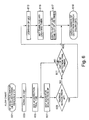
- the wireless network communication card of the present invention receives a signal from a latch circuit 215 if the power source of the apparatus in which the card should be installed is turned off or suspended, and in response to an access point detection request from a user, and thereby, a switch between the DC-DC converter 225 and the Vcc 3 W is turned on. As the result, power is supplied from the battery 233 to the AP detection circuit through the DC-DC converter 225 and the Vcc 3 W.
- step 611 until the AP detection trial time passes over a preset time, for example, 30 seconds to 1 minute, the flow returns back to the step 607 (No). After the AP detection trial time has passed over the preset time, the flow proceeds to the step 619 (Yes).
- a preset time for example, 30 seconds to 1 minute
Abstract
Description
-
- a) SSID/WEP of the AP is preliminarily conditionally assigned.
- b) A MAC address of the AP is preliminarily conditionally assigned.
- c) A preliminarily shared key of the AP (in case that the AP supports a WPA) is preliminarily conditionally assigned.
- d) The AP placed in a location registered to the location profile (Location Profile: setting for every location to use) assigned by the communication connection management program (IBM Access Connection Manager Program) is preliminarily assigned with some conditions.
Claims (3)
Applications Claiming Priority (2)
| Application Number | Priority Date | Filing Date | Title |
|---|---|---|---|
| JP2004-357037 | 2004-12-09 | ||
| JP2004357037A JP4433400B2 (en) | 2004-12-09 | 2004-12-09 | Wireless network communication card, device incorporating the card, device supporting wireless network communication, and method of detecting a wireless access point for wireless network communication |
Publications (2)
| Publication Number | Publication Date |
|---|---|
| US20060128415A1 US20060128415A1 (en) | 2006-06-15 |
| US9113397B2 true US9113397B2 (en) | 2015-08-18 |
Family
ID=36584701
Family Applications (1)
| Application Number | Title | Priority Date | Filing Date |
|---|---|---|---|
| US11/298,243 Active 2028-09-06 US9113397B2 (en) | 2004-12-09 | 2005-12-09 | Apparatus and method for detecting a wireless access point for wireless network communication |
Country Status (2)
| Country | Link |
|---|---|
| US (1) | US9113397B2 (en) |
| JP (1) | JP4433400B2 (en) |
Families Citing this family (37)
| Publication number | Priority date | Publication date | Assignee | Title |
|---|---|---|---|---|
| US7529925B2 (en) | 2005-03-15 | 2009-05-05 | Trapeze Networks, Inc. | System and method for distributing keys in a wireless network |
| US7551619B2 (en) | 2005-10-13 | 2009-06-23 | Trapeze Networks, Inc. | Identity-based networking |
| WO2007044986A2 (en) | 2005-10-13 | 2007-04-19 | Trapeze Networks, Inc. | System and method for remote monitoring in a wireless network |
| US7724703B2 (en) | 2005-10-13 | 2010-05-25 | Belden, Inc. | System and method for wireless network monitoring |
| US8638762B2 (en) * | 2005-10-13 | 2014-01-28 | Trapeze Networks, Inc. | System and method for network integrity |
| US7573859B2 (en) | 2005-10-13 | 2009-08-11 | Trapeze Networks, Inc. | System and method for remote monitoring in a wireless network |
| US20070259652A1 (en) * | 2006-05-01 | 2007-11-08 | Symbol Technologies, Inc. | Wireless Switches Incorporating a Light Source |
| US7558266B2 (en) | 2006-05-03 | 2009-07-07 | Trapeze Networks, Inc. | System and method for restricting network access using forwarding databases |
| US8966018B2 (en) | 2006-05-19 | 2015-02-24 | Trapeze Networks, Inc. | Automated network device configuration and network deployment |
| US7577453B2 (en) * | 2006-06-01 | 2009-08-18 | Trapeze Networks, Inc. | Wireless load balancing across bands |
| US7912982B2 (en) | 2006-06-09 | 2011-03-22 | Trapeze Networks, Inc. | Wireless routing selection system and method |
| US9191799B2 (en) | 2006-06-09 | 2015-11-17 | Juniper Networks, Inc. | Sharing data between wireless switches system and method |
| US8818322B2 (en) | 2006-06-09 | 2014-08-26 | Trapeze Networks, Inc. | Untethered access point mesh system and method |
| US9258702B2 (en) | 2006-06-09 | 2016-02-09 | Trapeze Networks, Inc. | AP-local dynamic switching |
| US8340110B2 (en) | 2006-09-15 | 2012-12-25 | Trapeze Networks, Inc. | Quality of service provisioning for wireless networks |
| JP4267018B2 (en) | 2006-10-06 | 2009-05-27 | レノボ・シンガポール・プライベート・リミテッド | Portable computer capable of wireless communication and method of detecting access point |
| US8072952B2 (en) | 2006-10-16 | 2011-12-06 | Juniper Networks, Inc. | Load balancing |
| US20080151844A1 (en) * | 2006-12-20 | 2008-06-26 | Manish Tiwari | Wireless access point authentication system and method |
| US7873061B2 (en) | 2006-12-28 | 2011-01-18 | Trapeze Networks, Inc. | System and method for aggregation and queuing in a wireless network |
| WO2008083339A2 (en) | 2006-12-28 | 2008-07-10 | Trapeze Networks, Inc. | Application-aware wireless network system and method |
| US8902904B2 (en) | 2007-09-07 | 2014-12-02 | Trapeze Networks, Inc. | Network assignment based on priority |
| US8238942B2 (en) | 2007-11-21 | 2012-08-07 | Trapeze Networks, Inc. | Wireless station location detection |
| US8150357B2 (en) | 2008-03-28 | 2012-04-03 | Trapeze Networks, Inc. | Smoothing filter for irregular update intervals |
| US8474023B2 (en) | 2008-05-30 | 2013-06-25 | Juniper Networks, Inc. | Proactive credential caching |
| US8978105B2 (en) | 2008-07-25 | 2015-03-10 | Trapeze Networks, Inc. | Affirming network relationships and resource access via related networks |
| US8238298B2 (en) | 2008-08-29 | 2012-08-07 | Trapeze Networks, Inc. | Picking an optimal channel for an access point in a wireless network |
| US8176328B2 (en) * | 2008-09-17 | 2012-05-08 | Alcatel Lucent | Authentication of access points in wireless local area networks |
| US8873523B2 (en) * | 2009-09-30 | 2014-10-28 | Apple Inc. | Methods and apparatus for solicited activation for protected wireless networking |
| US8830866B2 (en) * | 2009-09-30 | 2014-09-09 | Apple Inc. | Methods and apparatus for solicited activation for protected wireless networking |
| US8464061B2 (en) | 2010-08-30 | 2013-06-11 | Apple Inc. | Secure wireless link between two devices using probes |
| JP4929407B1 (en) | 2011-03-09 | 2012-05-09 | 株式会社東芝 | Information processing apparatus and display control method |
| WO2013153893A1 (en) * | 2012-04-10 | 2013-10-17 | 株式会社村田製作所 | Compound module |
| US20140365699A1 (en) * | 2013-06-11 | 2014-12-11 | Allied Telesis Holdings Kabushiki Kaisha | Adapter card for thin computing devices |
| JP6206717B2 (en) | 2013-12-13 | 2017-10-04 | パナソニックIpマネジメント株式会社 | Communication system and heat ray sensor terminal used therefor |
| US9998914B2 (en) | 2014-04-16 | 2018-06-12 | Jamf Software, Llc | Using a mobile device to restrict focus and perform operations at another mobile device |
| CN105049422B (en) * | 2015-06-25 | 2018-04-13 | 迪爱斯信息技术股份有限公司 | A kind of WIFI detections identification equipment, system and WIFI detection identification methods |
| CN108270646B (en) * | 2018-01-11 | 2021-08-17 | 北京讯飞乐知行软件有限公司 | Method and device for detecting electronic class board network |
Citations (15)
| Publication number | Priority date | Publication date | Assignee | Title |
|---|---|---|---|---|
| US4615599A (en) * | 1981-12-04 | 1986-10-07 | Canon Kabushiki Kaisha | Flash photographing system |
| USRE36712E (en) * | 1987-11-30 | 2000-05-23 | Kabushiki Kaisha Toshiba | Radio telephone apparatus |
| JP2001028836A (en) | 1999-07-12 | 2001-01-30 | Ntt Docomo Inc | Card adaptor with built-in battery and charging device with adaptor function |
| JP2002281044A (en) | 2001-03-22 | 2002-09-27 | Toshiba Corp | Card type electronic component |
| US20030011405A1 (en) * | 2001-07-16 | 2003-01-16 | Fujitsu Limited | Semiconductor integrated circuit |
| US20030067818A1 (en) * | 2001-09-12 | 2003-04-10 | Sharp Kabushiki Kaisha | Nonvolatile semiconductor memory device and method of detecting overerased cell |
| JP2003108271A (en) | 2001-09-18 | 2003-04-11 | Internatl Business Mach Corp <Ibm> | Computer apparatus, radio communication module, control method therefor, program and recording medium |
| JP2004056817A (en) | 2002-07-16 | 2004-02-19 | Lg Electronics Inc | Radio modem terminal for mobile communications |
| JP2004180115A (en) | 2002-11-28 | 2004-06-24 | Nec Infrontia Corp | Radio lan system |
| US6760850B1 (en) * | 2000-07-31 | 2004-07-06 | Hewlett-Packard Development Company, L.P. | Method and apparatus executing power on self test code to enable a wakeup device for a computer system responsive to detecting an AC power source |
| US20040150611A1 (en) * | 1999-08-18 | 2004-08-05 | Semiconductor Energy Laboratory Co., Ltd. | Display device and a driver circuit thereof |
| US6850103B2 (en) * | 2002-09-27 | 2005-02-01 | Texas Instruments Incorporated | Low leakage single-step latch circuit |
| JP2005057428A (en) | 2003-08-01 | 2005-03-03 | Nippon Telegr & Teleph Corp <Ntt> | Mobile information terminal and wireless communication method |
| US20070253395A1 (en) * | 2004-02-05 | 2007-11-01 | James Graves | Wireless network detector |
| US20070277047A1 (en) * | 2004-03-22 | 2007-11-29 | Dell Products L.P. | Information Handling System Including Wireless Scanning Feature |
-
2004
- 2004-12-09 JP JP2004357037A patent/JP4433400B2/en active Active
-
2005
- 2005-12-09 US US11/298,243 patent/US9113397B2/en active Active
Patent Citations (15)
| Publication number | Priority date | Publication date | Assignee | Title |
|---|---|---|---|---|
| US4615599A (en) * | 1981-12-04 | 1986-10-07 | Canon Kabushiki Kaisha | Flash photographing system |
| USRE36712E (en) * | 1987-11-30 | 2000-05-23 | Kabushiki Kaisha Toshiba | Radio telephone apparatus |
| JP2001028836A (en) | 1999-07-12 | 2001-01-30 | Ntt Docomo Inc | Card adaptor with built-in battery and charging device with adaptor function |
| US20040150611A1 (en) * | 1999-08-18 | 2004-08-05 | Semiconductor Energy Laboratory Co., Ltd. | Display device and a driver circuit thereof |
| US6760850B1 (en) * | 2000-07-31 | 2004-07-06 | Hewlett-Packard Development Company, L.P. | Method and apparatus executing power on self test code to enable a wakeup device for a computer system responsive to detecting an AC power source |
| JP2002281044A (en) | 2001-03-22 | 2002-09-27 | Toshiba Corp | Card type electronic component |
| US20030011405A1 (en) * | 2001-07-16 | 2003-01-16 | Fujitsu Limited | Semiconductor integrated circuit |
| US20030067818A1 (en) * | 2001-09-12 | 2003-04-10 | Sharp Kabushiki Kaisha | Nonvolatile semiconductor memory device and method of detecting overerased cell |
| JP2003108271A (en) | 2001-09-18 | 2003-04-11 | Internatl Business Mach Corp <Ibm> | Computer apparatus, radio communication module, control method therefor, program and recording medium |
| JP2004056817A (en) | 2002-07-16 | 2004-02-19 | Lg Electronics Inc | Radio modem terminal for mobile communications |
| US6850103B2 (en) * | 2002-09-27 | 2005-02-01 | Texas Instruments Incorporated | Low leakage single-step latch circuit |
| JP2004180115A (en) | 2002-11-28 | 2004-06-24 | Nec Infrontia Corp | Radio lan system |
| JP2005057428A (en) | 2003-08-01 | 2005-03-03 | Nippon Telegr & Teleph Corp <Ntt> | Mobile information terminal and wireless communication method |
| US20070253395A1 (en) * | 2004-02-05 | 2007-11-01 | James Graves | Wireless network detector |
| US20070277047A1 (en) * | 2004-03-22 | 2007-11-29 | Dell Products L.P. | Information Handling System Including Wireless Scanning Feature |
Also Published As
| Publication number | Publication date |
|---|---|
| JP4433400B2 (en) | 2010-03-17 |
| US20060128415A1 (en) | 2006-06-15 |
| JP2006166242A (en) | 2006-06-22 |
Similar Documents
| Publication | Publication Date | Title |
|---|---|---|
| US9113397B2 (en) | Apparatus and method for detecting a wireless access point for wireless network communication | |
| US11082913B2 (en) | Sensor provisioning in wireless sensor networks | |
| EP2978250B1 (en) | Method, related device, and system for configuring wireless local area network device | |
| US10064052B2 (en) | Methods for authenticating device-to-device communication | |
| JP5135445B2 (en) | Wireless LAN system, communication apparatus, and method for sharing setting information | |
| US20130057591A1 (en) | Wireless communication apparatus, projector apparatus, wireless communication system, and wireless communication method each for use in wireless lan | |
| US20150139210A1 (en) | Method and apparatus for access parameter sharing | |
| CN110431868B (en) | Wi-Fi hotspot connection method and terminal | |
| JP2005176021A (en) | Information processor and program | |
| KR20080049678A (en) | Determining identifiers for wireless networks with hidden identifiers | |
| US20140059643A1 (en) | Wireless communication apparatus, recording medium, and method | |
| CN102026263A (en) | Wireless communication network connection method | |
| US8856876B2 (en) | Apparatus and method for identifying wireless network provider in wireless communication system | |
| KR20180114466A (en) | Electronic apparatus and control method thereof | |
| JP2012227563A (en) | Communication device, processing method therefor, program, and communication system | |
| JP2004166090A (en) | Short-range communication equipment, portable terminal, control program of short-range communication equipment, control program of portable terminal and communication system | |
| US9271224B2 (en) | Communication apparatus, and communication method therefor | |
| JP2005073133A (en) | Method for updating security information, and radio terminal | |
| KR20080052050A (en) | Sdr terminal and method for providing wireless data service | |
| CN111684839B (en) | Sensor preset in wireless sensor network | |
| KR100760103B1 (en) | User authentication method of short-range communication devices | |
| KR20190057254A (en) | Method and apparatus for wi-fi connecting using wi-fi protected setup in a portable terminal | |
| JP2004128613A (en) | Base station supervisory apparatus in radio network, base station supervising method, and program thereof | |
| KR20070020987A (en) | System and method for bluetooth bonding |
Legal Events
| Date | Code | Title | Description |
|---|---|---|---|
| AS | Assignment |
Owner name: LENOVO (SINGAPORE) PTE. LTD., SINGAPORE Free format text: ASSIGNMENT OF ASSIGNORS INTEREST;ASSIGNORS:HORIKOSHI, HIDETO;ODAOHHARA, SHIGEFUMI;REEL/FRAME:017304/0100 Effective date: 20051205 |
|
| STCF | Information on status: patent grant |
Free format text: PATENTED CASE |
|
| MAFP | Maintenance fee payment |
Free format text: PAYMENT OF MAINTENANCE FEE, 4TH YEAR, LARGE ENTITY (ORIGINAL EVENT CODE: M1551); ENTITY STATUS OF PATENT OWNER: LARGE ENTITY Year of fee payment: 4 |
|
| AS | Assignment |
Owner name: LENOVO PC INTERNATIONAL, HONG KONG Free format text: ASSIGNMENT OF ASSIGNORS INTEREST;ASSIGNOR:LENOVO (SINGAPORE) PTE. LTD.;REEL/FRAME:049687/0855 Effective date: 20151001 |
|
| MAFP | Maintenance fee payment |
Free format text: PAYMENT OF MAINTENANCE FEE, 8TH YEAR, LARGE ENTITY (ORIGINAL EVENT CODE: M1552); ENTITY STATUS OF PATENT OWNER: LARGE ENTITY Year of fee payment: 8 |