US9294177B2 - System and method for transmit and receive antenna patterns calibration for time division duplex (TDD) systems - Google Patents
System and method for transmit and receive antenna patterns calibration for time division duplex (TDD) systems Download PDFInfo
- Publication number
- US9294177B2 US9294177B2 US14/467,415 US201414467415A US9294177B2 US 9294177 B2 US9294177 B2 US 9294177B2 US 201414467415 A US201414467415 A US 201414467415A US 9294177 B2 US9294177 B2 US 9294177B2
- Authority
- US
- United States
- Prior art keywords
- transmit
- relative amplitude
- antenna pattern
- receive antenna
- setting
- Prior art date
- Legal status (The legal status is an assumption and is not a legal conclusion. Google has not performed a legal analysis and makes no representation as to the accuracy of the status listed.)
- Active
Links
- 238000000034 method Methods 0.000 title claims abstract description 69
- 238000004891 communication Methods 0.000 claims abstract description 33
- 230000008054 signal transmission Effects 0.000 claims 4
- 230000005540 biological transmission Effects 0.000 description 33
- 238000005259 measurement Methods 0.000 description 28
- 238000010586 diagram Methods 0.000 description 10
- 238000012937 correction Methods 0.000 description 9
- 230000008569 process Effects 0.000 description 6
- 230000002441 reversible effect Effects 0.000 description 5
- 230000008901 benefit Effects 0.000 description 4
- 230000000694 effects Effects 0.000 description 4
- 238000005562 fading Methods 0.000 description 4
- 238000012935 Averaging Methods 0.000 description 3
- 230000006870 function Effects 0.000 description 3
- 230000000116 mitigating effect Effects 0.000 description 3
- 230000003595 spectral effect Effects 0.000 description 3
- 238000001228 spectrum Methods 0.000 description 3
- 238000011156 evaluation Methods 0.000 description 2
- 230000001788 irregular Effects 0.000 description 2
- 239000000463 material Substances 0.000 description 2
- 230000015654 memory Effects 0.000 description 2
- 238000012545 processing Methods 0.000 description 2
- 230000005855 radiation Effects 0.000 description 2
- 238000012360 testing method Methods 0.000 description 2
- 230000009471 action Effects 0.000 description 1
- 230000006399 behavior Effects 0.000 description 1
- 230000010267 cellular communication Effects 0.000 description 1
- 230000001427 coherent effect Effects 0.000 description 1
- 230000001934 delay Effects 0.000 description 1
- 238000001914 filtration Methods 0.000 description 1
- 238000012804 iterative process Methods 0.000 description 1
- 239000011159 matrix material Substances 0.000 description 1
- 238000012986 modification Methods 0.000 description 1
- 230000004048 modification Effects 0.000 description 1
- 238000012544 monitoring process Methods 0.000 description 1
- 230000008520 organization Effects 0.000 description 1
- 230000010363 phase shift Effects 0.000 description 1
- 230000003252 repetitive effect Effects 0.000 description 1
- 230000003068 static effect Effects 0.000 description 1
Images


Classifications
-
- H—ELECTRICITY
- H04—ELECTRIC COMMUNICATION TECHNIQUE
- H04B—TRANSMISSION
- H04B7/00—Radio transmission systems, i.e. using radiation field
- H04B7/02—Diversity systems; Multi-antenna system, i.e. transmission or reception using multiple antennas
- H04B7/04—Diversity systems; Multi-antenna system, i.e. transmission or reception using multiple antennas using two or more spaced independent antennas
- H04B7/06—Diversity systems; Multi-antenna system, i.e. transmission or reception using multiple antennas using two or more spaced independent antennas at the transmitting station
- H04B7/0613—Diversity systems; Multi-antenna system, i.e. transmission or reception using multiple antennas using two or more spaced independent antennas at the transmitting station using simultaneous transmission
- H04B7/0615—Diversity systems; Multi-antenna system, i.e. transmission or reception using multiple antennas using two or more spaced independent antennas at the transmitting station using simultaneous transmission of weighted versions of same signal
- H04B7/0617—Diversity systems; Multi-antenna system, i.e. transmission or reception using multiple antennas using two or more spaced independent antennas at the transmitting station using simultaneous transmission of weighted versions of same signal for beam forming
-
- H—ELECTRICITY
- H04—ELECTRIC COMMUNICATION TECHNIQUE
- H04B—TRANSMISSION
- H04B1/00—Details of transmission systems, not covered by a single one of groups H04B3/00 - H04B13/00; Details of transmission systems not characterised by the medium used for transmission
- H04B1/38—Transceivers, i.e. devices in which transmitter and receiver form a structural unit and in which at least one part is used for functions of transmitting and receiving
- H04B1/40—Circuits
- H04B1/54—Circuits using the same frequency for two directions of communication
- H04B1/56—Circuits using the same frequency for two directions of communication with provision for simultaneous communication in two directions
-
- H—ELECTRICITY
- H04—ELECTRIC COMMUNICATION TECHNIQUE
- H04B—TRANSMISSION
- H04B17/00—Monitoring; Testing
- H04B17/10—Monitoring; Testing of transmitters
- H04B17/11—Monitoring; Testing of transmitters for calibration
- H04B17/12—Monitoring; Testing of transmitters for calibration of transmit antennas, e.g. of the amplitude or phase
-
- H—ELECTRICITY
- H04—ELECTRIC COMMUNICATION TECHNIQUE
- H04B—TRANSMISSION
- H04B17/00—Monitoring; Testing
- H04B17/20—Monitoring; Testing of receivers
- H04B17/21—Monitoring; Testing of receivers for calibration; for correcting measurements
-
- H—ELECTRICITY
- H04—ELECTRIC COMMUNICATION TECHNIQUE
- H04B—TRANSMISSION
- H04B7/00—Radio transmission systems, i.e. using radiation field
- H04B7/02—Diversity systems; Multi-antenna system, i.e. transmission or reception using multiple antennas
- H04B7/04—Diversity systems; Multi-antenna system, i.e. transmission or reception using multiple antennas using two or more spaced independent antennas
- H04B7/06—Diversity systems; Multi-antenna system, i.e. transmission or reception using multiple antennas using two or more spaced independent antennas at the transmitting station
- H04B7/0613—Diversity systems; Multi-antenna system, i.e. transmission or reception using multiple antennas using two or more spaced independent antennas at the transmitting station using simultaneous transmission
- H04B7/0615—Diversity systems; Multi-antenna system, i.e. transmission or reception using multiple antennas using two or more spaced independent antennas at the transmitting station using simultaneous transmission of weighted versions of same signal
- H04B7/0665—Feed forward of transmit weights to the receiver
-
- H—ELECTRICITY
- H04—ELECTRIC COMMUNICATION TECHNIQUE
- H04B—TRANSMISSION
- H04B7/00—Radio transmission systems, i.e. using radiation field
- H04B7/02—Diversity systems; Multi-antenna system, i.e. transmission or reception using multiple antennas
- H04B7/04—Diversity systems; Multi-antenna system, i.e. transmission or reception using multiple antennas using two or more spaced independent antennas
- H04B7/06—Diversity systems; Multi-antenna system, i.e. transmission or reception using multiple antennas using two or more spaced independent antennas at the transmitting station
- H04B7/0613—Diversity systems; Multi-antenna system, i.e. transmission or reception using multiple antennas using two or more spaced independent antennas at the transmitting station using simultaneous transmission
- H04B7/0682—Diversity systems; Multi-antenna system, i.e. transmission or reception using multiple antennas using two or more spaced independent antennas at the transmitting station using simultaneous transmission using phase diversity (e.g. phase sweeping)
Definitions
- the present invention relates generally to wireless communication systems, and more specifically, to such systems configured to calibrate transmit and receive antenna patterns thereof.
- time division duplex is defined for the wireless communication systems is referred to in general for systems using the same frequency spectrum for methods of communications in a time division manner (for example, WiFi, and TDD-long term evolution (LTE) systems).
- MIMO communication system as defined herein is a communication system that may be used to improve the spectral efficiency, for example, by applying multiple inputs multiple outputs (MIMO) schemes, beam-forming, or nulling (interference mitigation/management). These operations usually require transmitter to have the knowledge of channel state information (CSI) so that a set of pre-coding weights may be set to the multiple data streams to exploit the channels for the multiple spatial channel transmission or to the same data stream to perform the beam-forming or nulling.
- CSI channel state information
- the receiver can feed the CSI or even the preferred pre-coding matrix (index) back to the transmitter. These feedbacks can consume some available bandwidth of the transmission in the opposite direction and reduce the data throughput. If transmission in both directions operate in the same spectrum, like TDD systems, the channels through the air are reversible and the channel information can be estimated by the receive device and then applied to the device's transmission. However, a complete transmission channel should be from the transmitter baseband to the receiver baseband, which includes various components inside the transmitter (e.g., digital to analog converter (DAC), up converter, power amplifier, filter) and receiver such as duplexer, linear amplifier (LNA), down converter, filter, analog to digital converter (ADC).
- DAC digital to analog converter
- LNA linear amplifier
- ADC analog to digital converter
- the transmit path and receive path may thus experience very different gain/loss and delays behavior, due to the different components used in both paths.
- Applying channel reciprocity without considering the different delay and gain/loss factors between the transmit/receive paths are therefore not valid and may not be accurate enough for the use by devices in TDD systems.
- These parameters may be factory calibrated. However, this calibration may be tedious and costly.
- one important element that jeopardizes reciprocity is antennas, which project slightly different radiation patterns at up and down links, due to differences in the Voltage Standing Wave Ratio (VSWR) in both directions. Antenna VSWR may not be practically calibrated in the factory, due to the cost and time of such procedures.
- VSWR Voltage Standing Wave Ratio
- Methods other than factory-calibration known in the art are capable of self-calibrating on transmit and receive paths of the device used in TDD systems. However, these methods may need an extra receive path with attenuator to calibrate transmit/receive (Tx/Rx) paths precisely on various power levels. This may limit the use of the known methods for the devices that are not equipped with the extra receive path.
- a calibration method is provided to improve TDD system performance for effectively overcoming the aforementioned difficulties inherent in the art.
- Embodiments of the present invention provide calibration of transmit and receive antenna patterns (e.g., beam peaks and nulls) for the devices in TDD systems, in which the channel reciprocity may be utilized so that the feedback of channel state information can be reduced or eliminated for beam-forming, nulling (e.g., interference mitigation) operations.
- transmit and receive antenna patterns e.g., beam peaks and nulls
- nulling e.g., interference mitigation
- Some of the TDD operations may not need the complete calibration information of the device's Tx and Rx paths for using channel reciprocity. Instead, matching Tx and Rx antenna pattern (peak and null), e.g., finding the weighting offset between the two antenna patterns, may be sufficient for the TDD device to take advantage of the channel reciprocity on certain applications.
- Embodiments of the invention provide a method for calibrating a device's transmit and receive antenna patterns (e.g., obtaining the weighting offset for the two antenna patterns), disclosed herein for a TDD device (for example, WiFi) to enable the use of the channel reciprocity.
- Embodiments of this method may be used in a radiation test or in the field using live signals.
- embodiments of the method may be done in a relatively static, stable and reliable environment e.g., Line-Of-Sight environment, high signal to noise plus interference (SINR), low mobility, minimal interference level, repetitive measurements that allow for averaging, and filtering out of elements that may distort the accuracy of the said calibration.
- SINR signal to noise plus interference
- the communication devices may include mobile devices such as a user equipment (UE).
- UE user equipment
- a UE may include any end user device with wireless connectivity such as a smart telephone, a laptop or a tablet personal computer (PC).
- the communication devices are not limited to UEs and may comprise any station in a communication network.
- the communication devices may include a plurality of M antennas for beam-forming or nulling operations, for example having tunable phases and optionally also adjustable amplitude. Each antenna may be used for both transmission and receiving.
- a communication device in a system according to embodiments of the invention may also comprise a plurality of radio circuits configured to transmit and receive via said antennas using TDD, for example by transmitting and receiving on a common channel.
- the device may also comprise a computer processor such as a baseband processor configured to calculate a weight setting difference between the transmit and the receive antenna pattern.
- the antenna pattern may be a peak-null pattern of the plurality of antennas operating together.
- one or more components such as the baseband processor and radio circuits may be configured to carry out all or part of the present invention.
- a communication device may perform a calibration processes to find the weight (for example, the relative phase setting or the relative amplitude setting or both) difference for matching transmit and receive antenna patterns (peaks and nulls) so that the channel reciprocity may be applied in the TDD system.
- the weight for example, the relative phase setting or the relative amplitude setting or both
- Embodiments of the invention also provide a method and system for configuring a station in a communications network comprising at least two antennas configured to operate together for both transmitting and receiving modes.
- a phase setting difference between the transmit and receive antenna patterns of said at least two of said antennas may be calculated or determined. This phase setting difference may be used to calculate or determine a relative amplitude setting for the transmit antenna pattern or a relative amplitude setting for the receive antenna pattern or both.
- Embodiments of the invention also provide a method and system for configuring a station in a communications network as described above, in which a predetermined phase difference between receive and transmit antenna patterns is used to determine a relative amplitude setting for the transmit antenna pattern or a relative amplitude setting for the receive antenna pattern or both.
- a predetermined phase difference between receive and transmit antenna patterns is used to determine a relative amplitude setting for the transmit antenna pattern or a relative amplitude setting for the receive antenna pattern or both.
- One or both of these relative amplitude settings may be determined in order to achieve a null in a signal received from or transmitted to another station by said at least two antennas.
- a time division (TD) user equipment (UE) or a Wi-Fi station may select base transmitter station or access point (e.g. selecting SSID) signal, in a reliable environment as indicated above, and perform peak and null tuning on both transmissions by iteratively manipulating phases and amplitudes using a quality indicator, so that the maximum/the minimum is achieved.
- base transmitter station or access point e.g. selecting SSID
- a quality indicator may be data rate; so peak may be defined as amplitudes and phases setting to the two or more antennas which maximizes data rate, and null—as ones which minimize it; this may be applied to both to up and down links.
- the station may upload a large file (for example with a constant packet length) at the same location for the receive beam calibration.
- peak/null may be established also via received signal level measurement, and therefore an iterative process may not be required.
- Embodiments of the invention may start with an arbitrary phase (amongst two or more transmitting antenna) and equal amplitudes, and check the upload data rate (or the number of re-transmission time) until steady, then repeat the data rate measurements after changing to a new relative phase. The same may be done with relative amplitude. The transmit beam peak and null may then be found.
- a particular calibration data point may be given up.
- the null may be difficult to obtain, for example if the received power has fallen below the noise level or the acknowledgement for a null transmission cannot be obtained.
- the peak relative phase may be reversed (e.g., minus 180 degrees) for the phase of the null of the two-antenna beam.
- this calibration method may be applied to other TDD networks (for example a non WiFi network).
- the received system broadcast (for system message) channel power or pilot power may be used for UE receive beam calibration.
- a threshold of SINR may be set (e.g., 25 dB) for the receive beam peak.
- a reasonable data rate may be set as the threshold.
- the calibration may be calculated or determined to be valid only when there are data over these set thresholds.
- the said calibration process may include measuring transmit and receive antenna patterns of the device; or finding out the weights (for example, the relative phase setting between two antennas or the relative amplitude setting or both) of the antenna pattern nulls or peaks.
- the calculation of weight setting difference may be based on nulls only.
- the said antenna pattern measurements may be carried out with the direct radio frequency (RF) signal measurement or through system performance evaluation (for example, MCS—modulation coding set).
- RF radio frequency
- MCS modulation coding set
- the said antenna pattern measurements may be performed at the location that has line-of-sight view to another communication device in a communication system such as the WiFi access point (AP) (or base station).
- the location may also be close to the other communication device to minimize the interference and to mitigate the fading situation.
- the line-of-sight view may be confirmed if the difference of received signal strength indicator (RSSI) from the receive antennas are within a pre-set range, such as threshold (for example, 3 dB), and if the fluctuation (due to fading) of RSSI from each of the receive antennas are within a pre-set threshold (for example, 3 dB).
- RSSI received signal strength indicator
- the closeness of the calibrated device to an AP may be confirmed if the received signal powers from each of the receive antennas are within a pre-set range (for example, ⁇ 25 to ⁇ 50 dBm in WiFi device calibration).
- the receive antenna pattern may be obtained through for example a coherent combining process (for example, the maximum ratio combining) on the received signals from receive antennas, while varying the combining weight of the signals over a pre-set range (for example, varying the relative phase over a range of 0 to 360 degrees).
- a coherent combining process for example, the maximum ratio combining
- the weight setting for the null or peak of receive antenna pattern may be obtained by performing the channel estimation on the signal from each receive antenna.
- the transmit antenna pattern may be represented by system performance parameter, for example, the measured data rate or feedback data rate or feedback channel information, instead of transmit RF power, versus the relative phase between the two antenna signals.
- the communication device may transmit the same signal (same data from a large file) with equally amplitude (power) through the transmit antennas while changing the relative phase between the two signals (or antennas), and collects the system performance information (for example, MCS—modulation coding set) to represent the transmit antenna pattern.
- MCS modulation coding set
- the data rate (for example, MCS—Modulation and Coding Set fed back from base station, or the transmit data rate count when the fixed data rate transmission and re-transmission scheme is used) may be collected to represent the transmit antenna pattern.
- MCS Modulation and Coding Set fed back from base station, or the transmit data rate count when the fixed data rate transmission and re-transmission scheme is used
- the system parameters (for example, data rate) for a transmit null may not be reliably obtainable, due to the low signal-to-noise ratio at null.
- a computer processor may be configured to extrapolate from two reliable measured transmit data rates and their corresponding phase settings.
- the weight setting for the null may be extrapolated from the parameter slopes (for example, data rate changes) on the relatively reliable data on both sides of the null.
- the computer processor may be configured to calculate the offset of phase settings for transmit and receive antenna patterns by comparing the phase settings of the said transmit and receive nulls.
- the weight setting for the null of an antenna pattern may be confirmed with the weight setting for the peak, which should occur at 180 degrees away from the null setting.
- the antenna pattern calibration may be applied to the antenna pattern formed by any number of antennas.
- Embodiments of the invention also provide a method comprising selecting a calibration site location for a station having plurality of antennas and radio circuit.
- the site location may have a line of sight view with another station in a communications network, such as an access point (AP).
- the method may then comprise monitoring a broadcast message from said another station (AP) and channel estimating on a receive signal from each radios/antennas representing a channel of the station.
- FIG. 1 shows that a station may have the unmatched transmit and receive antenna patterns when assigning the same weight (relative phase) for transmit antennas and receive antennas, according some embodiments of the present invention
- FIG. 2 shows that the station may have the matched transmit and receive antenna patterns with a different weight (relative phase) setting according some embodiments of the present invention
- FIG. 3 depicts the procedures for measuring receive antenna patterns according some embodiments of the present invention
- FIG. 4 depicts the procedures for weight setting measurements for the receive antenna peak and null using a channel estimation method according some embodiments of the present invention
- FIG. 5 depicts the procedures for weight setting measurements for the transmit antenna peak and null according some embodiments of the present invention
- FIG. 6 depicts the procedure of measuring the weight setting and the Tx data rate for the system with dynamically pre-scheduled transmission according some embodiments of the present invention
- FIG. 7 depicts the procedure of measuring the weight setting and the Tx data rate for the system with non-scheduled transmission according some embodiments of the present invention
- FIG. 8 illustrates the exemplary measured data from which the phase setting for the transmit null may be extrapolated according some embodiments of the present invention
- FIG. 9 depicts the procedure for calculating the phase settings for the transmit null and peak using the reliably measured data rates (versus relative phases) according some embodiments of the present invention.
- FIG. 10 shows the exemplary collected data from which the calibration results may be obtained by comparing the phase settings of receive null and transmit null (e.g., ⁇ RN and ⁇ TN ) according some embodiments of the present invention
- FIG. 11 is a schematic illustration of a channel description and basic components of a TDD MIMO system according to some embodiments of the present invention.
- FIG. 12 is a flow chart showing a method of calculating or determining relationship between amplitude ratio and received signal according to some embodiments of the present invention.
- FIGS. 13A and 13B are graphs showing two different sets of results that may be obtained using the flow of FIG. 12 , according to some embodiments of the present invention.
- FIG. 14 is a graph showing the effect of variation of amplitude ratio on received signal strength according to some embodiments of the present invention.
- TDD time division duplex spectroscopy
- a single channel e.g., the same or overlapping frequency spectrum
- both stations and their served access point in WiFi systems use the same frequency channel alternatively in time to communicate each other.
- TDD cellular communication e.g., between a mobile device and a base station, may periodically alternate between uplink transmissions (e.g. from the mobile device to a base station for a predetermined uplink interval or period, such as, 5 milliseconds (ms)) and downlink transmissions (e.g. from a base station to a mobile device or UE for a predetermined downlink period, such as, 5 ms).
- the base station typically coordinates the alternating timing between uplink (UL) and downlink (DL) transmissions.
- Embodiments of the present invention propose the calibration procedures to derive the correction factors (weight difference) on matching transmit and receive antenna patterns of a TDD device.
- This correction factor information may enable the device perform the beam-forming and/or nulling application for improving the spectral efficiency in TDD (e.g., WiFi) systems.
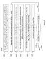
- FIG. 1 is a block diagram showing a system 100 according to some embodiments of the present invention.
- System 100 shows a WiFi (i.e., TDD) system with the unmatched transmit (uplink) and receive (downlink) antenna patterns.
- Station 110 may have a baseband processor 124 , M antennas 120 - 1 . . . , 120 -M, and M radios, or radio circuits, 122 - 1 . . . , 122 -M, each antenna may be used for both transmit and receive and any of the antennas 120 - 1 . . . , 120 -M may be configured to operate together for both transmitting and receiving modes;
- Access Point (AP) 140 may also have multiple (M) antennas and radios.
- T indicates the relative transmit gain with the relative phase of transmit antennas set at ⁇ 0 .
- R indicates the relative receive gain with the same relative phase ( ⁇ 0 ) set for the receive antennas.
- the transmit antenna pattern and the receive antenna pattern are not matched; with the same relative phase setting ( ⁇ 0 ), the transmit gain (T) is on the peak of the antenna patterns while the receive gain (R) is not.
- FIG. 2 is a block diagram 200 illustrating the same system in 100 but with different relative phase settings for transmit antennas and receive antennas ( ⁇ 0 and ⁇ 1 , respectively) according some embodiments of the present invention.
- the receive antenna pattern 230 - 2 is then matched to the transmit antenna pattern 230 - 1 , with these relative phase settings; both transmit and receive gains (T and R) are on the peaks of transmit and receive antenna patterns.
- the calibration is to find the difference between the relative phase settings ( ⁇ 0 and ⁇ 1 ) so that the TDD device may perform beam-forming and nulling without the feedback from AP (or base station) and thus improve the spectral efficiency of the TDD system.
- Embodiments of the invention include the calibration procedures.
- Embodiments of the calibration procedures are configured to obtain the difference of weight (relative phase) settings between the transmit null (peak) and the receive null (peak).
- FIG. 3 is a flowchart 300 illustrating example procedures for measuring receive antenna patterns according some embodiments of the present invention.
- Step 310 shows that the calibration (e.g., receive and transmit antenna pattern measurements) may be performed at the location where the device is, which preferably has a Line-Of-Sight (LOS) view to the AP (or base station) and close to the AP to minimize the impact of the multiple paths, interference, and fading.
- the line-of-sight view may be defined quantitatively.
- LOS may be confirmed if the difference of received signal strength indicator (RSSI) from the receive antennas are within a pre-set threshold (for example, 3 dB) and if the fluctuation (due to fading) of received signal strength indicator (RSSI) from each of the receive antennas are within a pre-set threshold (for example, 3 dB).
- the closeness of the calibrated device to AP may be defined quantitatively as well. For the example of the WiFi device calibration, the closeness may be confirmed if the received signal powers from each of the receive antennas are within a pre-set range (for example, ⁇ 25 to ⁇ 50 dBm).
- Step 320 shows that the device may monitor the constant signal broadcasted from AP (or base station), for example, the Service Set identifier (SSID) from WiFi AP or system broadcast message (including pilot) from base station.
- An initial relative phase ⁇ Ri may be set in Step 320 as well.
- Step 340 shows that the combined signal powers may then be averaged over many repeated measurements until the average value becomes stable (for example, the average values fluctuates within a pre-set value say, 1 dB or 20%).
- the collected signal strength may be discarded and not be input into the averaging if the discrepancy of signal strengths (a and b) exceed a pre-set threshold (for example 1 dB).
- Step 350 indicates that the received signal measurement and the signal combining using the same relative phase will be repeated if the averaged value is not relative stable.
- 360 shows that the averaged combined power and the corresponding relative phase setting may be stored and a new relative phase may be set by adding the phase resolution (say, 10 degrees) to the current relative phase setting.
- Step 370 shows that the receive antenna patterns measurement is complete and may be stopped once the measurements have through the full range (360 degrees) of the relative phase settings. Otherwise, continue the measurement with the new phase setting.
- the calibration is to find the weight (relative phase) between transmit and receive antenna patterns.
- the antenna patterns may have a single null (or peak).
- the antenna pattern offset may be obtained by comparing the relative phase settings of transmit null (or peak) and receive null (or peak).
- the calibration may then only measure the phase setting for the null (or peak), instead of the measurement for the whole antenna pattern.
- FIG. 4 is a flowchart 400 illustrating that the calibrated device may perform channel estimation to obtain the relative phase setting for the receive null and peak according some embodiments of the present invention.
- the baseband processor may deduce the antenna pattern by applying channel estimation on the received signal from each antenna.
- Step 410 selects the calibration site that has a LOS view and close to AP (same location and orientation for the Tx antenna pattern measurement).
- the calibration device monitors the constant broadcast message that has a pilot (or reference signal), shown in Step 420 .
- Step 430 shows that the calibrated device may perform a channel estimation on the pilot or reference signal.
- Step 440 indicates that the relative phase ⁇ between the two (receive antennas) channels may be found and stored.
- ⁇ RN ⁇ RP +180(degrees) (2)
- the receive null is deduced by adding 180 degrees to the phase setting of the receive peak.
- Step 460 shows that the phase settings may be separately averaged over several channel estimations.
- Step 470 indicates that the receive null (peak) measurement is complete and may be stopped once the averaged values become stable. Stability can be achieved when, for example, the fluctuation of the averaged values is less than a pre-set value (say, 20%).
- a direct RF signal measurement may not be feasible for the transmit antenna pattern. Instead, the system performance, for example, data rate evaluation, may be used for representing the transmit antenna pattern.
- a transmit antenna pattern may be presented by collected data rates versus the relative phase settings of the transmit antennas.
- the calibrated device may transmit the equal and constant amplitude signal through the transmit antennas and collect the data rate information for various relative phase settings (between the transmit antennas).
- FIG. 5 is a flowchart 500 depicting an example procedure to measure the transmit antenna pattern according some embodiments of the present invention.
- Step 510 indicates that transmit antenna measurement should be done at the same site and the same orientation for receive antenna pattern measurement.
- Step 520 shows that the calibrated device may perform User Datagram Protocol (UDP) to upload random data until transmit antenna measurement is completed.
- UDP User Datagram Protocol
- the data rate count may be based on the feedback data rate information or counted by the calibrated device itself, depending on the system data transmission scheme.
- Step 530 shows that if the transmit data rate is dynamically scheduled (based on the channel quality) by the receiver (e.g., base station), for example, in TDD-LTE system, the feedback data rate (MCS—Modulation/Coding Set) may then be used for representing the antenna pattern, shown on step 540 .
- the receiver e.g., base station
- MCS Modulation/Coding Set
- FIG. 6 An embodiment of a procedure for the data rate collection based on feedback is shown in FIG. 6 in flowchart 600 according some embodiments of the present invention.
- the transmit data rate is not scheduled by the receiver station, the calibrated device may then count the transmit data rate itself 550 .
- FIG. 7 is a flowchart 700 showing an embodiment of a procedure for self-counting on the transmit data rate.
- the data rate count may be limited by the system setup and/or the receiver capability.
- the received signal (and SNR) may be too low to support any transmit data rate, due to that the transmission is on or around the transmit null.
- the received signal (and SNR) may far exceed the required SNR to support highest transmit data rate of the system setup when the transmission is on or around the transmission peak.
- 560 calculate the phase settings for transmit null and peak. Example detailed calculation and procedure are described in FIGS. 8 and 9 .
- the feedback data rate information may be collected for representing the transmit antenna pattern.
- Flowchart 600 of FIG. 6 depicts an example procedure to collect the transmit data rate.
- the same signal with equal amplitude is transmitted through the transmit antennas, for example under the control of a baseband processor, while varying the relative phase between the two signals, and collects the data rate information for the said transmit antenna pattern measurement.
- Feedback information may be used to determine data rates for performing transmit antenna pattern measurement.
- Step 610 shows that the calibrated device set a relative phase ⁇ Ti and equal amplitude for the two transmit signals/antennas for the UDP transmission.
- Step 620 indicates that the calibrated device monitor (and use) the feedback MCS until it becomes stable, For example, the feedback MCS is not changed for consecutive pre-set number (say, 10) of feedbacks.
- the relative phase setting and the feedback data rate (MCS) may then be stored, shown on 630 .
- Step 640 shows that a new phase setting by adding the pre-set phase resolution (say 10 degree) may be set for continuous UDP transmission.
- Step 650 shows that if data rate collection has through the whole range of the phase settings (360 degrees), the calibrated device may stop the data rate collection and proceed to calculate the phase setting for transmit null and peak shown on 660 . Otherwise, it continues the data rate collection with the new phase setting.
- the calibrated device may count its transmit data rate for representing the transmit antenna pattern.
- Flowchart 700 of FIG. 7 depicts an example procedure to self-count the transmit data rate.
- Step 710 shows that the calibrated device set a relative phase ⁇ Ti and equal amplitude for the two transmit signals/antennas for the UDP transmission.
- the transmission may be with irregular data size and on the irregular time period, and may be even unsuccessful.
- Step 720 indicates that the calibrated device may sum the transmitted data for each successful transmission and calculate the data rate with the sum of the transmission periods until the aggregate data rate becomes stable. The relative phase setting and the stable aggregate data rate may then be stored, shown on 730 .
- Step 740 shows that a new phase setting by adding the pre-set phase resolution (say 10 degree) may be set.
- Step 750 shows that if data rate collection has through the whole range of the phase settings (360 degrees), the calibrated device may stop the data rate collection and proceed to calculate the phase setting for transmit null and peak shown on 760 . Otherwise, it continues the data rate collection with the new phase setting.
- FIG. 8 is a graph diagram 800 showing the example of the collected data rate and relative phase settings for obtaining the phase setting of the transmit null and peak according some embodiments of the present invention.
- R 1 and R 2 are the measured data rates in the midrange of the all measured data rates selected for calculate the phase setting for the transmit null.
- the reasons for selecting the data rates in the midrange are that the data rate measured around the transmit null may be too noisy (and unreliable) and the data rate measured around the transmit peak may be under-stated due to the system limitation and hence not accurate.
- Each measured data rate may have two phase settings; phase settings of ⁇ 1 and ⁇ 4 result in the measured data rate R 1 and ⁇ 2 and ⁇ 3 for R 2 , shown in 800 .
- phase settings ( ⁇ 1 , ⁇ 2 , ⁇ 3 , and ⁇ 4 ) and the selected data rate (R1 and R2) may form two straight lines S 1 ( 810 ) and S 2 ( 820 ).
- S 2: R [ ( R 1 ⁇ R 2 )/( ⁇ 4 ⁇ 3 )]* ⁇ +( R 2 * ⁇ 4 ⁇ R 1 * ⁇ 3 )/( ⁇ 4 ⁇ 3 ) (4)
- the phase setting of transmit null, ⁇ TN is the phase setting corresponding to the intersect point ( 830 ) of the two lines.
- FIG. 9 is a flowchart 900 depicting an example procedure calculate the phase settings of the transmit null and peak according to some embodiments of the present invention.
- Step 910 shows that two data rates R 1 and R 2 in the midrange of all the measured data rates may be selected to calculate the phase setting of transmit null.
- Step 920 is the procedure to find the phase settings for the two selected data rate ( ⁇ 1 , ⁇ 4 , ⁇ 2 , and ⁇ 3 ).
- Step 930 shows that the phase setting of transmit null, ⁇ TN , may be calculated according Equation 5.
- the phase offset of transmit and receive antenna pattern may be obtained by comparing the phase settings for transmit and receive nulls, ⁇ TN and ⁇ RN .
- FIG. 10 shows exemplary collected data A 00 for transmit and receive antenna patterns formed by two antennas according to some embodiments of the present invention.
- a 10 and A 20 indicate receive and the transmit antenna patterns.
- the calibration procedure according to embodiments of the present invention finds 30 degree phase shift between these two antenna patterns (A 10 and A 20 ).
- Embodiments of the invention may be used to calculate or determine a relative amplitude setting for the transmit antenna pattern and a relative amplitude setting for the receive antenna pattern, or both.
- the difference between these two relative amplitude settings may be determined as a weight setting difference between transmit and receive antenna patterns.
- the amplitude setting difference may be determined based on nulls in the antenna patterns. The determination of amplitude setting is particularly useful for signal cancellation.
- FIG. 11 illustrates an example TDD MIMO system. Embodiments of the invention may be implemented in any station in a communications network.
- FIG. 11 illustrates embodiments of the invention using a UE and a base station or access point by way of example. The roles of the UE and the base station may be reversed and each may be substituted for another station.
- the system shown in FIG. 11 includes UE 1110 comprising, in this example, two antennas 1111 and 1112 and respective radios, or radio circuits, 1113 and 1114 .
- the principles of embodiments of the invention may be extended to any number M of antennas and radios. Any of the antennas may be configured to operate together for both transmitting and receiving modes.
- the system also comprises base station 1150 which may also have M antennas and radios, only one of which is shown in FIG. 11 , antenna 1151 and radio 1152 .
- Each antenna on these two devices, UE 1110 and base station 1150 may be used for both transmit and receive, but not simultaneously, in the TDD MIMO operation.
- the channels available over the air (between the antennas) are reversible.
- Each radio 1113 , 1114 and 1152 comprises respective amplifiers for the transmit and receive paths.
- UE 1110 comprises a baseband processor 1120 and base station 1150 comprises a baseband processor 1160 .
- FIG. 12 A possible method of calculating or determining the amplitude ratio according to embodiments of the invention will now be described with reference to FIG. 12 .
- Some or all of the operations of FIG. 12 may be performed in the baseband processor, e.g. baseband processor 1120 , for example by suitable programming of the baseband processor.
- ⁇ TN and ⁇ RN are the relative phase settings for transmit null and receive null determined by any of the procedures described above with reference to FIGS. 1 to 10 and ⁇ 12 is the phase correction for channel reciprocity, also termed “calibrated phase” or phase setting difference.
- the phase setting difference is an example of a weight setting difference that may be determined as described with reference to FIGS. 1 to 10 . It will be appreciated that this phase adjustment or calibrated phase is intended to be applied on switching from reception to transmission (and a reverse adjustment is applied on switching back) to achieve, in the illustrated example of FIG. 11 , a null at the base station, or at least to minimize the amplitude of the combination of signals received by or transmitted to the two antennas 1111 and 1112 .
- this adjustment of amplitude is applied in addition to the phase adjustment to further improve the nulling effect of combining two signals.
- the phase between transmission and reception is adjusted in order to match the transmit and receive antenna patterns, for example using the predetermined phase difference ⁇ 12.
- the process of calculating or determining the phase and amplitude corrections may be repeated at intervals.
- a broadcast message from the base station or AP is monitored, for example this may be the SSID.
- channel estimation is performed on the received signal from each of the antennas, r1 and r2.
- new weight settings B12 and ⁇ 12 are determined for the receive null based on the channel estimation. These weight settings are for relative phase and amplitude between the two antennas 1111 and 1112 in receive mode. It should be noted here that both ⁇ RN and ⁇ 12 represent the relative phase between antennas to achieve a receive null. ⁇ RN is derived from a process of averaging described with reference to FIG. 4 whereas ⁇ 12 may be based on one channel estimation.
- the channel estimation in operation 1230 may be performed before each collection of “transmit” data to obtain values of r1 and r2.
- Z is a real number representing the difference in amplitude ratio between transmit and receive antenna patterns and may be varied within a predetermined range in iterations of operation 1250 , for example ⁇ Y to +Y in dB. Operation 1250 may be performed with different values for t1/t2 at intervals, for example of one second.
- the transmission date rate for each value of t1/t2 may be determined, for example based on feedback information received from the base station 1150 .
- the relationship between data rate and amplitude ratio t1/t2 may be registered and recorded or stored at operation 1260 . Operations 1230 to 1260 may be repeated until it is determined at operation 1270 that data rates for all values of Z have been recorded.
- the amplitude ratio t1/t2 is based on the receive relative amplitude setting B12, and the receive relative phase setting ⁇ 12 as well as the receive/transmit phase setting difference ⁇ 12. Also according to embodiments of the invention, the receive relative amplitude setting B12, and the receive relative phase setting ⁇ 12 are newly determined, for example based on channel estimation, for each iteration of operations 1250 and 1260 , transmitting and recording data rate.
- the lowest registered data rate may be identified and the corresponding amplitude ratio defined as the amplitude ratio setting for the transmit null. This may also be referred to as amplitude “imbalance” and may be measured in dB.
- FIG. 13B shows an example set of results with more than one minimum data rate, such as might occur due to system limitations, or data transmission being unsuccessful, due to low SNR at the null, where the “slope method” may be used to extrapolate the virtual minimum data rate and corresponding amplitude ratio.
- FIG. 14 is a graph illustrating the effect of the variation of amplitude ratio on the received signal strength.
- the x axis represents relative phase in degrees between two signals and the y axis represents signal strength relative to the peak, measured in dB.
- the different curves represent the relationship between signal strength of the combined signal and relative phase for different relative amplitudes measured in dB.
- the relationship at 0 dB which is not possible to achieve in practice, results in a null at infinity, and the other curves show that a difference of only 0.1 dB in relative amplitude can make a difference of a higher order in strength of the combined signal.
- the determination of relative amplitude in the manner described above, using feedback from the other station where the null is to be achieved, may be performed by suitable configuration of the baseband processor without the need for any additional hardware.
- aspects of the present invention may be embodied as a system, method or an apparatus. Accordingly, aspects of the present invention may take the form of an entirely hardware embodiment, an entirely software embodiment (including firmware, resident software, micro-code, etc.) or an embodiment combining software and hardware aspects that may all generally be referred to herein as a “circuit,” “module” or “system.”
- a baseband processor or other processor may be configured to carry out methods of the present invention by for example executing code or software.
- each block in the flowchart or block diagrams may represent a module, segment, or portion of code, which comprises one or more executable instructions for implementing the specified logical function(s).
- the functions noted in the block may occur out of the order noted in the figures. For example, two blocks shown in succession may, in fact, be executed substantially concurrently, or the blocks may sometimes be executed in the reverse order, depending upon the functionality involved.
Abstract
Description
ΦRP=−Φ (1)
ΦRN=ΦRP+180(degrees) (2)
In other words the receive null is deduced by adding 180 degrees to the phase setting of the receive peak.
S1: R=[(R 1 −R 2)/(Φ1−Φ2)]*Φ+(R 2*Φ1 −R 1*Φ2)/(Φ1−Φ2) (3)
S2: R=[(R 1 −R 2)/(Φ4−Φ3)]*Φ+(R 2*Φ4 −R 1*Φ3)/(Φ4−Φ3) (4)
The phase setting of transmit null, ΦTN, is the phase setting corresponding to the intersect point (830) of the two lines. Using Equation 3 and 4, the phase setting of transmit null may be obtained,
ΦTN=(Φ1*Φ3−Φ2*Φ4)/(Φ1−Φ2+Φ3,−Φ4) (5)
840 shows the phase setting for the transmit peak, which is 180 degree away from the transmit null.
ΦTP=(ΦTN+180)degrees (6)
r1=C R1 *h 1a *S r2=C R2 *h 2a *S (7)
where:
-
- S is the transmitted signal
- C represents the gain or loss caused by components inside the transmitter/receiver
- h represents the effect of the over-the-air channel.
Y1=h a1 *C T1 t1 and Y2=h a2 *C T2 *t2 (8)
It can be assumed that
h 1a =h a1 and h 2a =h a2 (9)
since these are reciprocal over the air channels.
Y1/Y2=−1 or Y 1 =Y 2 *e j 180 (10)
From
r 1 *t 1 =S*Y 1 *C r1 /C t1 and r2*t2=S*Y2*C r2/C t2 (11)
and
(r2*t2)/(r1*t1)=(Y2/Y1)*(C r2 *C t1)/(c r1 *C t2) (12)
We now define:
R 12 =r1/r2, T 12 =t1/t2, C 12=(C r2 *C t1)/(C r1 *C t2) (13)
and
C 12=(C T1 *C R2)/(C T2 *C R1)=A 12 e jΦ12 (14)
where A12 and Φ12 are the unknown amplitude and phase corrections for channel reciprocity.
then C 12=1/(R 12 *T 12)
becomes: C 12 Rx null=(r2*t2)(B12*r1*e jθ12 *t1) (15)
It is then useful to calculate or determine what adjustment of phase and amplitude is needed between transmit and receive modes in order to achieve phase nulling in transmit mode. The goal is to achieve Y1=Y2*ej 180, which is to adjust the transmit phase between t1 and t2 by Φ12 starting from receive nulling correction θ12, and the amplitude ratio by A12 from receive amplitude correction B12, so starting from equation (15)
C 12 Rx null+Tx null_=(r2*t2)/(B12*A12*r1*e j(θ12+Φ12) *t1) (16)
Φ12=ΦTN−ΦRN (17)
(t1/t2)=(r2)/(r1*B12*Z*e j(θ12+Φ12)) (18)
Claims (21)
Priority Applications (1)
| Application Number | Priority Date | Filing Date | Title |
|---|---|---|---|
| US14/467,415 US9294177B2 (en) | 2013-11-26 | 2014-08-25 | System and method for transmit and receive antenna patterns calibration for time division duplex (TDD) systems |
Applications Claiming Priority (5)
| Application Number | Priority Date | Filing Date | Title |
|---|---|---|---|
| US201361909135P | 2013-11-26 | 2013-11-26 | |
| US201461946273P | 2014-02-28 | 2014-02-28 | |
| US201461973362P | 2014-04-01 | 2014-04-01 | |
| US14/281,358 US9014066B1 (en) | 2013-11-26 | 2014-05-19 | System and method for transmit and receive antenna patterns calibration for time division duplex (TDD) systems |
| US14/467,415 US9294177B2 (en) | 2013-11-26 | 2014-08-25 | System and method for transmit and receive antenna patterns calibration for time division duplex (TDD) systems |
Related Parent Applications (1)
| Application Number | Title | Priority Date | Filing Date |
|---|---|---|---|
| US14/281,358 Continuation-In-Part US9014066B1 (en) | 2013-11-26 | 2014-05-19 | System and method for transmit and receive antenna patterns calibration for time division duplex (TDD) systems |
Publications (2)
| Publication Number | Publication Date |
|---|---|
| US20150146584A1 US20150146584A1 (en) | 2015-05-28 |
| US9294177B2 true US9294177B2 (en) | 2016-03-22 |
Family
ID=53182605
Family Applications (1)
| Application Number | Title | Priority Date | Filing Date |
|---|---|---|---|
| US14/467,415 Active US9294177B2 (en) | 2013-11-26 | 2014-08-25 | System and method for transmit and receive antenna patterns calibration for time division duplex (TDD) systems |
Country Status (1)
| Country | Link |
|---|---|
| US (1) | US9294177B2 (en) |
Cited By (4)
| Publication number | Priority date | Publication date | Assignee | Title |
|---|---|---|---|---|
| WO2018141297A1 (en) * | 2017-02-06 | 2018-08-09 | Mediatek Inc. | Mechanism for beam reciprocity determination and uplink beam management |
| CN110431767A (en) * | 2017-03-22 | 2019-11-08 | 高通股份有限公司 | Utilize the user equipment antenna calibration of the auxiliary from other equipment |
| CN111133691A (en) * | 2017-09-28 | 2020-05-08 | 华为技术有限公司 | Method, device and system for calibrating array antenna |
| US11228104B2 (en) * | 2018-07-24 | 2022-01-18 | Mitsubishi Electric Corporation | Calibration device and calibration method of array antenna, array antenna, and program storage medium |
Families Citing this family (12)
| Publication number | Priority date | Publication date | Assignee | Title |
|---|---|---|---|---|
| US10582401B2 (en) * | 2016-03-08 | 2020-03-03 | Aurora Insight Inc. | Large scale radio frequency signal information processing and analysis system |
| WO2017218282A1 (en) * | 2016-06-17 | 2017-12-21 | Intel IP Corporation | System and method for physical uplink request channel design |
| KR102481291B1 (en) * | 2016-09-12 | 2022-12-26 | 삼성전자 주식회사 | Method and apparatus for calibrating phase of antenna in wireless communication system using unlicensed band |
| US11165521B2 (en) * | 2016-12-13 | 2021-11-02 | Amimon Ltd. | Analog signal transmission with multiple antennas |
| US10432240B1 (en) | 2018-05-22 | 2019-10-01 | Micron Technology, Inc. | Wireless devices and systems including examples of compensating power amplifier noise |
| US10917140B2 (en) * | 2018-10-03 | 2021-02-09 | Nokia Technologies Oy | Dynamic signaling of coherence levels |
| US10763905B1 (en) | 2019-06-07 | 2020-09-01 | Micron Technology, Inc. | Wireless devices and systems including examples of mismatch correction scheme |
| EP3981090B1 (en) * | 2019-06-07 | 2023-09-27 | Telefonaktiebolaget LM Ericsson (publ) | Calibration for antenna elements of a multi-antenna structure |
| US11528600B2 (en) * | 2019-09-24 | 2022-12-13 | Qualcomm Incorporated | Massive MIMO physical layer based cryptography |
| US11005581B1 (en) * | 2020-02-07 | 2021-05-11 | Facebook, Inc. | Calibration of an antenna array that uses low-resolution phase shifters |
| US10972139B1 (en) | 2020-04-15 | 2021-04-06 | Micron Technology, Inc. | Wireless devices and systems including examples of compensating power amplifier noise with neural networks or recurrent neural networks |
| US11496341B2 (en) | 2020-08-13 | 2022-11-08 | Micron Technology, Inc. | Wireless devices and systems including examples of compensating I/Q imbalance with neural networks or recurrent neural networks |
Citations (338)
| Publication number | Priority date | Publication date | Assignee | Title |
|---|---|---|---|---|
| US4044359A (en) | 1962-01-09 | 1977-08-23 | General Electric Company | Multiple intermediate frequency side-lobe canceller |
| US4079318A (en) | 1975-06-23 | 1978-03-14 | Nippon Electric Company, Ltd. | Space diversity receiving system with phase-controlled signal combining at intermediate frequency stage |
| US4359738A (en) | 1974-11-25 | 1982-11-16 | The United States Of America As Represented By The Secretary Of The Navy | Clutter and multipath suppressing sidelobe canceller antenna system |
| US4540985A (en) | 1978-05-23 | 1985-09-10 | Westinghouse Electric Corp. | Angle width discriminator/altitude line detector radar |
| US4628320A (en) | 1964-04-29 | 1986-12-09 | General Electric Company | Cancellation of scatter jamming |
| US5162805A (en) | 1975-02-19 | 1992-11-10 | The United States Of America As Represented By The Secretary Of The Navy | Frequency diversity sidelobe canceller |
| US5363104A (en) | 1974-02-28 | 1994-11-08 | Lockheed Sanders, Inc. | Jamming signal cancellation system |
| US5444762A (en) | 1993-03-08 | 1995-08-22 | Aircell, Inc. | Method and apparatus for reducing interference among cellular telephone signals |
| US5732075A (en) | 1995-02-24 | 1998-03-24 | Alcatel N.V. | Assignment of a carrier frequency in an SDMA radio system |
| US5915215A (en) | 1990-05-02 | 1999-06-22 | Harris Canda, Inc. | Private cellular telephone system |
| US5936577A (en) | 1996-10-18 | 1999-08-10 | Kabushiki Kaisha Toshiba | Adaptive antenna |
| US5940033A (en) | 1998-01-20 | 1999-08-17 | The United States Of America As Represented By The Secretary Of The Army | Apparatus, methods and computer program for evaluating multiple null forming antenna processors and jammers |
| US6018317A (en) | 1995-06-02 | 2000-01-25 | Trw Inc. | Cochannel signal processing system |
| US6026081A (en) | 1996-07-05 | 2000-02-15 | Nec Corporation | Method of controlling power on forward link in a cellular |
| US6046655A (en) | 1997-11-10 | 2000-04-04 | Datron/Transco Inc. | Antenna feed system |
| US6094165A (en) | 1997-07-31 | 2000-07-25 | Nortel Networks Corporation | Combined multi-beam and sector coverage antenna array |
| US6101399A (en) | 1995-02-22 | 2000-08-08 | The Board Of Trustees Of The Leland Stanford Jr. University | Adaptive beam forming for transmitter operation in a wireless communication system |
| US6163695A (en) | 1997-04-16 | 2000-12-19 | Nec Corporation | Mobile communication system and mobile communication method thereof |
| US6167286A (en) | 1997-06-05 | 2000-12-26 | Nortel Networks Corporation | Multi-beam antenna system for cellular radio base stations |
| US6215812B1 (en) | 1999-01-28 | 2001-04-10 | Bae Systems Canada Inc. | Interference canceller for the protection of direct-sequence spread-spectrum communications from high-power narrowband interference |
| US6226507B1 (en) | 1998-02-03 | 2001-05-01 | Ericsson Inc. | Apparatus and method for selecting between a plurality of antennas utilized by a microcellular communications terminal for reception of a signal |
| US6230123B1 (en) | 1997-12-05 | 2001-05-08 | Telefonaktiebolaget Lm Ericsson Publ | Noise reduction method and apparatus |
| US6259683B1 (en) | 1996-11-28 | 2001-07-10 | Oki Electric Industry Co., Ltd. | Mobile communication system for accomplishing handover with phase difference of frame sync signals corrected |
| US6297772B1 (en) | 1974-09-23 | 2001-10-02 | The United States Of America As Represented By The Secretary Of The Navy | Predicting coherent sidelobe canceller |
| US20010029326A1 (en) | 1991-03-07 | 2001-10-11 | Diab Mohamed Kheir | Signal processing apparatus and method |
| US20010038665A1 (en) | 2000-03-03 | 2001-11-08 | Jens Baltersee | Method and rake receiver for phasor estimation in communication systems |
| US6321077B1 (en) | 1998-04-24 | 2001-11-20 | Harada Industry Co., Ltd. | Reception control system for automobile |
| US6335953B1 (en) | 1992-05-08 | 2002-01-01 | Axonn, L.L.C. | Enhanced frequency agile radio |
| US20020024975A1 (en) | 2000-03-14 | 2002-02-28 | Hillel Hendler | Communication receiver with signal processing for beam forming and antenna diversity |
| EP1189303A2 (en) | 2000-09-14 | 2002-03-20 | NTT DoCoMo, Inc. | Beam forming method and apparatus in a wireless communication system |
| US6370378B1 (en) | 1998-06-29 | 2002-04-09 | Nec Corporation | Cellular communicating network and method for locating mobile stations using hierarchically arranged databases |
| US6377783B1 (en) | 1998-12-24 | 2002-04-23 | At&T Wireless Services, Inc. | Method for combining communication beams in a wireless communication system |
| US20020051430A1 (en) | 2000-10-31 | 2002-05-02 | Hideo Kasami | Wireless communication system, weight control apparatus, and weight vector generation method |
| US6393282B1 (en) | 1999-01-14 | 2002-05-21 | Kabushiki Kaisha Toshiba | Mobile radio communication terminal device with base station searching function |
| US20020065107A1 (en) | 2000-10-16 | 2002-05-30 | Wireless Online, Inc. | Method and system for calibrating antenna towers to reduce cell interference |
| US20020085643A1 (en) | 2000-12-28 | 2002-07-04 | Dean Kitchener | MIMO wireless communication system |
| US20020107013A1 (en) | 2001-02-06 | 2002-08-08 | Shane Fitzgerald | Method and apparatus for intelligent dynamic frequency reuse |
| US20020115474A1 (en) | 2001-02-14 | 2002-08-22 | Ntt Docomo, Inc. | Communication control method and apparatus in mobile communication system |
| US20020181437A1 (en) | 2001-04-26 | 2002-12-05 | Ntt Docomo, Inc | Data link transmission control methods, mobile communication systems, data link transmission control apparatus, base stations, mobile stations, mobile station control programs, and computer-readable recording media |
| US20020181426A1 (en) | 2001-03-02 | 2002-12-05 | Sherman Matthew J. | Interference suppression methods for 802.11 |
| US20030087645A1 (en) | 2001-11-08 | 2003-05-08 | Kim Byoung-Jo J. | Frequency assignment for multi-cell IEEE 802.11 wireless networks |
| WO2003047033A1 (en) | 2001-11-21 | 2003-06-05 | Lockheed Martin Corporation | Scaleable antenna array architecture using standard radiating subarrays and amplifying/beamforming assemblies |
| US20030114162A1 (en) | 2001-05-31 | 2003-06-19 | Chheda Ashvin H. | Method and apparatus for orthogonal code management in CDMA systems using smart antenna technology |
| US6584115B1 (en) | 1998-06-25 | 2003-06-24 | Nec Corporation | Multiuser interference canceler for DS-CDMA system |
| US20030153360A1 (en) | 2002-02-08 | 2003-08-14 | Burke Joseph P. | Method and apparatus for transmit pre-correction in wireless communications |
| US20030153322A1 (en) | 2002-02-08 | 2003-08-14 | Burke Joseph P. | Transmit pre-correction in a wireless communication system |
| WO2003073645A1 (en) | 2002-02-26 | 2003-09-04 | Nortel Networks Limited | Radio communications device with adaptive antenna array for mimo systems |
| US20030186653A1 (en) | 1998-05-14 | 2003-10-02 | Behzad Mohebbi | Reducing interference in cellular mobile communication networks |
| US20030203743A1 (en) | 2002-04-22 | 2003-10-30 | Cognio, Inc. | Multiple-Input Multiple-Output Radio Transceiver |
| US20030203717A1 (en) | 1998-04-27 | 2003-10-30 | Chuprun Jeffery Scott | Satellite based data transfer and delivery system |
| US6647276B1 (en) | 1999-09-14 | 2003-11-11 | Hitachi, Ltd. | Antenna unit and radio base station therewith |
| US20040023693A1 (en) | 2002-08-01 | 2004-02-05 | Ntt Docomo, Inc. | Base station connection method, radio network controller, and mobile station |
| US6697622B1 (en) | 1999-09-06 | 2004-02-24 | Nit Docomo, Inc. | Control method of searching neighboring cells, mobile station, and mobile communication system |
| US6697633B1 (en) | 1995-06-02 | 2004-02-24 | Northrop Grummar Corporation | Method permitting increased frequency re-use in a communication network, by recovery of transmitted information from multiple cochannel signals |
| US20040056795A1 (en) | 2001-11-20 | 2004-03-25 | Telefonaktiebolaget Lm Ericsson | Downlink load sharing by beam selection |
| US20040063455A1 (en) | 2002-08-07 | 2004-04-01 | Extricom Ltd. | Wireless LAN with central management of access points |
| US20040081144A1 (en) | 2002-09-17 | 2004-04-29 | Richard Martin | System and method for access point (AP) aggregation and resiliency in a hybrid wired/wireless local area network |
| US6735182B1 (en) * | 1998-11-19 | 2004-05-11 | Nippon Telegraph And Telephone Corporation | Adaptive array antenna system |
| US20040121810A1 (en) | 2002-12-23 | 2004-06-24 | Bo Goransson | Using beamforming and closed loop transmit diversity in a multi-beam antenna system |
| US20040125900A1 (en) | 2002-12-31 | 2004-07-01 | Jung-Tao Liu | Method of determining the capacity of each transmitter antenna in a multiple input/multiple out/put (MIMO) wireless system |
| US20040125899A1 (en) | 2002-12-30 | 2004-07-01 | Yingxue Li | Method and system for adaptively combining signals |
| US20040142696A1 (en) | 2002-12-10 | 2004-07-22 | Data Flow Systems, Inc. | Radio communication system employing spectral reuse transceivers |
| US20040147266A1 (en) | 2003-01-20 | 2004-07-29 | Samsung Electronics Co., Ltd. | System and method for supporting multimedia broadcast/multicast service in a non-tracking area |
| US20040156399A1 (en) | 2002-08-07 | 2004-08-12 | Extricom Ltd. | Wireless LAN control over a wired network |
| US20040166902A1 (en) | 2003-01-21 | 2004-08-26 | Dan Castellano | Method and system for reducing cell interference using advanced antenna radiation pattern control |
| US20040198292A1 (en) | 2002-06-27 | 2004-10-07 | Smith Martin S. | Wireless transmitter, transceiver and method |
| US20040228388A1 (en) | 2003-04-25 | 2004-11-18 | Matti Salmenkaita | Data transmission method, system and network element |
| US20040235527A1 (en) | 1999-10-19 | 2004-11-25 | Kathrein-Werke Kg | High speed fixed wireless voice/data systems and methods |
| US6834073B1 (en) | 2000-05-26 | 2004-12-21 | Freescale Semiconductor, Inc. | System and method for baseband removal of narrowband interference in ultra wideband signals |
| US20040264504A1 (en) | 2003-06-24 | 2004-12-30 | Samsung Electronics Co., Ltd. | Apparatus and method for enhancing transfer rate using a direct link protocol (DLP) and multiple channels in a wireless local area network (LAN) using a distributed coordination function (DCF) |
| US6842460B1 (en) | 2001-06-27 | 2005-01-11 | Nokia Corporation | Ad hoc network discovery menu |
| US20050068230A1 (en) | 2003-09-29 | 2005-03-31 | Munoz Michael S. | Reducing co-channel interference in satellite communications systems by antenna re-pointing |
| US20050068918A1 (en) | 2003-09-25 | 2005-03-31 | Ashok Mantravadi | Hierarchical coding with multiple antennas in a wireless communication system |
| US20050075140A1 (en) | 2003-10-02 | 2005-04-07 | Toshiba America Research Inc. | Harmonized Adaptive Arrays |
| US20050085266A1 (en) * | 2003-10-20 | 2005-04-21 | Sanyo Electric Co., Ltd. | Base station device achieving effective use of frequencies by changing structures of antennas |
| US20050129155A1 (en) | 2003-12-12 | 2005-06-16 | Pioneer Corporation | Receiver, receiving method, reception controlling program, and recording medium |
| US6914890B1 (en) | 1999-08-05 | 2005-07-05 | Nokia Corporation | Apparatus, and associated method, for sequencing transmission of data |
| US20050147023A1 (en) | 2003-12-30 | 2005-07-07 | Intel Corporation | Method and apparatus for implementing downlink SDMA in a wireless network |
| US20050163097A1 (en) | 2004-01-28 | 2005-07-28 | Samsung Electronics Co., Ltd | Method of efficiently transmitting data during a handover in a wideband radio access network |
| US6927646B2 (en) | 2002-07-12 | 2005-08-09 | Filtronic Lk Oy | Bypass arrangement for low-noise amplifier |
| US6934541B2 (en) | 2001-03-01 | 2005-08-23 | Hitachi Kokusai Electric Inc. | Communication device |
| US20050245224A1 (en) | 2004-02-04 | 2005-11-03 | Fujitsu Ten Limited | Receiver |
| US20050250544A1 (en) | 2004-05-07 | 2005-11-10 | Stephen Grant | Base station, mobile terminal device and method for implementing a selective-per-antenna-rate-control (S-PARC) technique in a wireless communications network |
| US20050254513A1 (en) | 2004-05-14 | 2005-11-17 | Interdigital Technology Corporation | Method of selectively adjusting the configuration of an access point antenna to enhance mobile station coverage |
| US20050265436A1 (en) | 2004-06-01 | 2005-12-01 | Samsung Electronics Co., Ltd. | Method and apparatus for channel state feedback using arithmetic coding |
| US6975582B1 (en) | 1995-07-12 | 2005-12-13 | Ericsson Inc. | Dual mode satellite/cellular terminal |
| US20050286440A1 (en) | 2004-06-24 | 2005-12-29 | Meshnetworks, Inc. | System and method for adaptive rate selection for wireless networks |
| US20050287962A1 (en) | 2004-06-25 | 2005-12-29 | Mehta Neelesh B | RF-based antenna selection in MIMO systems |
| US20060041676A1 (en) | 2001-01-16 | 2006-02-23 | Sherman Matthew J | Interference suppression methods for 802.11 |
| US20060094372A1 (en) | 2004-10-29 | 2006-05-04 | Samsung Electronics Co., Ltd. | Method for uplink scheduling in communication system using frequency hopping-orthogonal frequency division multiple access scheme |
| US20060092889A1 (en) | 2004-08-25 | 2006-05-04 | Daniel Lyons | High density WLAN system |
| US20060098605A1 (en) | 2003-04-07 | 2006-05-11 | Shaolin Li | Method of secure communications in a wireless distribution system |
| US20060111149A1 (en) | 2001-11-29 | 2006-05-25 | Interdigital Technology Corporation | System and method utilizing dynamic beam forming for wireless communication signals |
| US20060135097A1 (en) | 2003-12-10 | 2006-06-22 | Wang James J | Wireless communication system using a plurality of antenna elements with adaptive weighting and combining techniques |
| US7068628B2 (en) | 2000-05-22 | 2006-06-27 | At&T Corp. | MIMO OFDM system |
| US20060183503A1 (en) | 2002-09-09 | 2006-08-17 | Interdigital Technology Corporation | Reducing the effect of signal interference in null areas caused by overlapping antenna patterns |
| US20060203850A1 (en) | 2005-03-14 | 2006-09-14 | Johnson Walter L | Method and apparatus for distributing timing information in an asynchronous wireless communication system |
| US20060227854A1 (en) | 2005-04-07 | 2006-10-12 | Mccloud Michael L | Soft weighted interference cancellation for CDMA systems |
| US20060264184A1 (en) | 2005-02-17 | 2006-11-23 | Interdigital Technology Corporation | Method and apparatus for selecting a beam combination of multiple-input multiple-output antennas |
| US20060270343A1 (en) | 2005-04-07 | 2006-11-30 | Interdigital Technology Corporation | Method and apparatus for antenna mapping selection in MIMO-OFDM wireless networks |
| US20060271969A1 (en) | 2005-05-18 | 2006-11-30 | Masaaki Takizawa | Wireless communication system, wireless relay unit and wireless terminal constituting the wireless communication system, and wireless communication method |
| US20060285507A1 (en) | 2005-06-17 | 2006-12-21 | Kinder Richard D | Using mini-beacons in a wireless network |
| US7177663B2 (en) | 2003-05-27 | 2007-02-13 | Interdigital Technology Corporation | Multi-mode radio with interference cancellation circuit |
| US20070041398A1 (en) | 2000-11-03 | 2007-02-22 | At&T Corp. | Tiered contention multiple access (TCMA): a method for priority-based shared channel access |
| US7190964B2 (en) | 2001-08-20 | 2007-03-13 | Telefonaktiebolaget Lm Ericsson (Publ) | Reverse link power control in 1xEV-DV systems |
| US20070058581A1 (en) | 2001-07-05 | 2007-03-15 | Mathilde Benveniste | Hybrid coordination function (hcf) access through tiered contention and overlapped wireless cell mitigation |
| US20070076675A1 (en) | 2005-10-04 | 2007-04-05 | Via Technologies Inc. | Hyper throughput method for wirless local area network |
| US20070093261A1 (en) | 2005-10-24 | 2007-04-26 | Jilei Hou | Iterative interference cancellation system and method |
| US20070097918A1 (en) | 2005-10-27 | 2007-05-03 | Motorola, Inc. | Mobility enhancement for real time service over high speed downlink packet access (hsdpa) |
| US20070115882A1 (en) | 2005-11-08 | 2007-05-24 | Conexant Systems, Inc | Symmetric transmit opportunity (TXOP) truncation |
| US20070152903A1 (en) | 2005-12-30 | 2007-07-05 | Micro Mobio | Printed circuit board based smart antenna |
| US7257425B2 (en) | 2003-12-02 | 2007-08-14 | Motia | System and method for providing a smart antenna |
| US20070217352A1 (en) | 2006-01-05 | 2007-09-20 | Samsung Electronics Co., Ltd. | Method and apparatus for transmitting control frame to hidden node in wireless LAN |
| US20070223380A1 (en) | 2006-03-22 | 2007-09-27 | Gilbert Jeffrey M | Mechanism for streaming media data over wideband wireless networks |
| US20070249386A1 (en) | 2006-03-22 | 2007-10-25 | Broadcom Corporation, A California Corporation | Client device characterization of other client device transmissions and reporting of signal qualities to access point(s) |
| US7299072B2 (en) | 2003-02-28 | 2007-11-20 | Fujitsu Limited | Apparatus for time division multi-sector wireless LAN |
| US20070298742A1 (en) | 2006-06-27 | 2007-12-27 | Qualcomm Incorporated | Method and system for providing beamforming feedback in wireless communication systems |
| US20080043867A1 (en) | 2006-08-18 | 2008-02-21 | Qualcomm Incorporated | Feedback of precoding control indication (pci) and channel quality indication (cqi) in a wireless communication system |
| US20080051037A1 (en) | 2005-12-29 | 2008-02-28 | Molnar Karl J | BASE STATION AND METHOD FOR SELECTING BEST TRANSMIT ANTENNA(s) FOR SIGNALING CONTROL CHANNEL INFORMATION |
| US20080081671A1 (en) | 2006-10-03 | 2008-04-03 | Motorola, Inc. | Mobile assisted downlink beamforming with antenna weight feedback |
| US20080095163A1 (en) | 2006-10-23 | 2008-04-24 | Wai Chen | Method and communication device for routing unicast and multicast messages in an ad-hoc wireless network |
| US20080108352A1 (en) | 2006-10-27 | 2008-05-08 | Michael Montemurro | Link quality measurements based on data rate and received power level |
| US20080125120A1 (en) | 2002-10-18 | 2008-05-29 | Gallagher Michael D | Registration Messaging in an Unlicensed Mobile Access Telecommunications System |
| US20080144737A1 (en) | 2006-12-19 | 2008-06-19 | Qualcomm Incorporated | Beamspace-time coding based on channel quality feedback |
| US7392015B1 (en) | 2003-02-14 | 2008-06-24 | Calamp Corp. | Calibration methods and structures in wireless communications systems |
| US7391757B2 (en) | 2002-10-30 | 2008-06-24 | Hewlett-Packard Development Company, L.P. | Wireless LAN |
| US20080165732A1 (en) | 2001-11-08 | 2008-07-10 | Kim Byoung-Jo J | Frequency assignment for multi-cell IEEE 802.11 wireless networks |
| US20080238808A1 (en) | 2007-02-15 | 2008-10-02 | Mitsubishi Electric Corporation | Diversity receiver |
| US20080240314A1 (en) | 2007-03-27 | 2008-10-02 | Qualcomm Incorporated | Channel estimation with effective co-channel interference suppression |
| US20080247370A1 (en) | 2005-09-30 | 2008-10-09 | Daqing Gu | Training Signals for Selecting Antennas and Beams in Mimo Wireless Lans |
| US20080267142A1 (en) | 2004-06-18 | 2008-10-30 | Stellaris Ltd. | Distributed Antenna Wlan Access-Point System and Method |
| US20080280571A1 (en) | 2007-05-11 | 2008-11-13 | Broadcom Corporation, A California Corporation | RF transceiver with adjustable antenna assembly |
| US20080285637A1 (en) | 2005-11-29 | 2008-11-20 | Interuniversitair Microelektronica Centrum Vzw (Imec) | Device and method for calibrating mimo systems |
| US20090003299A1 (en) | 2004-01-08 | 2009-01-01 | Interdigital Technology Corporation | Method for clear channel assessment optimization in a wireless local area network |
| US7474676B2 (en) | 2004-09-10 | 2009-01-06 | Mitsubishi Electric Research Laboratories, Inc. | Frame aggregation in wireless communications networks |
| US20090028225A1 (en) | 2007-07-17 | 2009-01-29 | Viasat, Inc. | Modular Satellite Transceiver |
| US20090046638A1 (en) | 2003-10-01 | 2009-02-19 | Rappaport Theodore S | Wireless network system and method |
| US7499109B2 (en) | 2003-07-30 | 2009-03-03 | Samsung Electronics Co., Ltd. | Method and apparatus for receiving digital television signals using space diversity and beam-forming |
| US20090058724A1 (en) | 2007-09-05 | 2009-03-05 | Samsung Electronics Co., Ltd. | Method and system for analog beamforming in wireless communication systems |
| US7512083B2 (en) | 2003-04-07 | 2009-03-31 | Shaolin Li | Single chip multi-antenna wireless data processor |
| US20090121935A1 (en) | 2007-11-12 | 2009-05-14 | Samsung Electronics Co., Ltd. | System and method of weighted averaging in the estimation of antenna beamforming coefficients |
| US20090137206A1 (en) | 2007-11-23 | 2009-05-28 | Texas Instruments Incorporated | Apparatus for and method of bluetooth and wireless local area network coexistence using a single antenna in a collocated device |
| US20090154419A1 (en) | 2007-12-17 | 2009-06-18 | Shousei Yoshida | Scheduling method for multi-user mimo |
| US20090190541A1 (en) | 2008-01-28 | 2009-07-30 | Saied Abedi | Communication systems |
| JP2009182441A (en) | 2008-01-29 | 2009-08-13 | Mitsubishi Electric Corp | Communication device and calibration method |
| US20090227255A1 (en) | 2008-03-10 | 2009-09-10 | Telefonaktiebolaget Lm Ericsson (Publ) | Enhanced cell scanning |
| US20090239486A1 (en) | 2002-03-01 | 2009-09-24 | Ipr Licensing, Inc. | Apparatus for antenna diversity using joint maximal ratio combining |
| US7606528B2 (en) | 2006-11-10 | 2009-10-20 | Northrop Grumman Corporation | Distributed conformal adaptive antenna array for SATCOM using decision direction |
| US20090268616A1 (en) | 2005-11-21 | 2009-10-29 | Takahiro Hosomi | Mobile station, downstream transmission rate control method, and downstream transmission rate control program |
| US20090279478A1 (en) | 2008-05-06 | 2009-11-12 | Motorola, Inc. | Method and apparatus for facilitating dynamic cooperative interference reduction |
| US20090285331A1 (en) | 2002-03-21 | 2009-11-19 | Ipr Licensing, Inc. | Control of power amplifiers in devices using transmit beamforming |
| JP2009278444A (en) | 2008-05-15 | 2009-11-26 | Mitsubishi Electric Corp | Distortion compensation device |
| US7634015B2 (en) | 2006-02-10 | 2009-12-15 | Intel Corporation | Mobile station and method for channel sounding using a single radio frequency transmitter chain in a multiple-input multiple-output (MIMO) system |
| US20090323608A1 (en) | 2008-06-30 | 2009-12-31 | Kabushiki Kaisha Toshiba | Apparatus and method for wireless communication |
| US20090322610A1 (en) | 2006-11-10 | 2009-12-31 | Philip Edward Hants | Phased array antenna system with electrical tilt control |
| US20090322613A1 (en) | 2008-06-30 | 2009-12-31 | Interdigital Patent Holdings, Inc. | Method and apparatus to support single user (su) and multiuser (mu) beamforming with antenna array groups |
| US20100002656A1 (en) | 2008-07-03 | 2010-01-07 | Qualcomm Incorporated | Opportunistic relay scheduling in wireless communications |
| US7646744B2 (en) | 2003-04-07 | 2010-01-12 | Shaolin Li | Method of operating multi-antenna wireless data processing system |
| US20100037111A1 (en) | 2008-08-06 | 2010-02-11 | Sun Microsystems, Inc. | Method and apparatus for testing delay faults |
| US20100040369A1 (en) | 2008-08-13 | 2010-02-18 | Jun Zhao | Time synchronization method and device in passive optical network and passive optical network |
| US20100087227A1 (en) | 2008-10-02 | 2010-04-08 | Alvarion Ltd. | Wireless base station design |
| US20100111039A1 (en) | 2008-11-03 | 2010-05-06 | Samsung Electronics Co., Ltd. | Method and apparatus for controlling discontinuous reception in mobile communication system |
| US20100117890A1 (en) | 2008-11-10 | 2010-05-13 | Motorola, Inc. | Antenna reciprocity calibration |
| US7719993B2 (en) | 2004-12-30 | 2010-05-18 | Intel Corporation | Downlink transmit beamforming |
| US20100135420A1 (en) | 2007-06-29 | 2010-06-03 | China Mobile Communications Corporation | Antenna multiplexing system and method of smart antenna and multiple-input multiple-output antenna |
| US20100150013A1 (en) | 2007-05-29 | 2010-06-17 | Mitsubishi Electric Corporation | Calibration method, communication system, frequency control method, and communication device |
| US7742000B2 (en) | 2005-05-31 | 2010-06-22 | Tialinx, Inc. | Control of an integrated beamforming array using near-field-coupled or far-field-coupled commands |
| US20100172429A1 (en) | 2007-05-29 | 2010-07-08 | Hiroyuki Nagahama | Digital broadcasting receiving apparatus |
| US7769107B2 (en) | 2004-06-10 | 2010-08-03 | Intel Corporation | Semi-blind analog beamforming for multiple-antenna systems |
| WO2010085854A1 (en) | 2009-02-02 | 2010-08-05 | Commonwealth Scientific And Industrial Research Organisation | Hybrid adaptive antenna array |
| US20100195560A1 (en) | 2009-01-30 | 2010-08-05 | Oki Electric Industry Co., Ltd. | Packet relay system and wireless node |
| US20100195601A1 (en) | 2009-01-29 | 2010-08-05 | Stichting Imec Nederland | Access method and data frame structure for use in body area networks |
| US20100208712A1 (en) | 2009-02-17 | 2010-08-19 | Wavion Ltd. | Enhancing WLAN performance in the presence of interference |
| US20100222011A1 (en) | 2005-04-04 | 2010-09-02 | Broadcom Corporation | Gain control in a multiple rf transceiver integrated circuit |
| US20100234071A1 (en) | 2009-03-12 | 2010-09-16 | Comsys Communication & Signal Processing Ltd. | Vehicle integrated communications system |
| US20100232355A1 (en) | 2009-03-13 | 2010-09-16 | Harris Corporation | Asymmetric broadband data network |
| US20100278063A1 (en) | 2009-04-29 | 2010-11-04 | Samsung Electronics Co. Ltd. | Method for controlling interference |
| US20100283692A1 (en) | 2006-04-27 | 2010-11-11 | Rayspan Corporation | Antennas, devices and systems based on metamaterial structures |
| US20100285752A1 (en) | 2009-05-11 | 2010-11-11 | Nec Laboratories America, Inc. | Beamforming methods and systems employing measured power at a receiver to perform channel estimation |
| US20100291931A1 (en) | 2007-10-31 | 2010-11-18 | Mitsubishi Electric Corporation | Mobile communication system, base station, mobile station, and base station installation method |
| US20100303170A1 (en) | 2007-05-10 | 2010-12-02 | Xiaolong Zhu | Method and apparatus for pre-processing data to be transmitted in multiple-input communication system |
| US20100316043A1 (en) | 2007-02-06 | 2010-12-16 | Panasonic Corporation | Radio communication method and radio communication device |
| US7876848B2 (en) | 2004-07-27 | 2011-01-25 | Samsung Electronics Co., Ltd. | Apparatus and method for transmitting a data stream in a wireless communication system with multiple antennas |
| US20110019639A1 (en) | 2009-05-22 | 2011-01-27 | Jeyhan Karaoguz | Enterprise Level Management in a Multi-Femtocell Network |
| US7881401B2 (en) | 2006-11-17 | 2011-02-01 | Infineon Technologies Ag | Transmitter arrangement and signal processing method |
| US20110032849A1 (en) | 2009-08-07 | 2011-02-10 | Fimax Technology Limited | Systems and methods for mitigating interference between access points |
| US20110032972A1 (en) | 2009-08-07 | 2011-02-10 | Motia, Inc. | Economical, RF transparent, selective code phased array antenna processor |
| US7898478B2 (en) | 2007-02-28 | 2011-03-01 | Samsung Electronics Co., Ltd. | Method and system for analog beamforming in wireless communication systems |
| US7904086B2 (en) | 2006-10-02 | 2011-03-08 | Board Of Regents, The University Of Texas System | Method and computer program for handoff of mobile devices between wireless systems |
| US7904106B2 (en) | 2006-11-22 | 2011-03-08 | Samsung Electronics Co., Ltd. | Method and apparatus of adaptively allocating transmission power for beamforming combined with orthogonal space-time block codes based on symbol error rate in distributed wireless communication system |
| US20110085532A1 (en) | 2002-08-26 | 2011-04-14 | Scherzer Shimon B | Space-time-power scheduling for wireless networks |
| US20110085465A1 (en) | 2008-06-09 | 2011-04-14 | Telefonaktiebolaget L M Ericsson (Publ) | Method and system and device for if/irat measurement allocation |
| US7933255B2 (en) | 2003-04-07 | 2011-04-26 | Bellow Bellows Llc | Multi-antenna wireless data processing system |
| US20110105036A1 (en) | 2009-11-04 | 2011-05-05 | Motorola, Inc. | Method and apparatus for sensing presence of an incumbent signal on a secondary radio channel |
| US20110116489A1 (en) | 2009-11-13 | 2011-05-19 | Interdigital Patent Holdings, Inc. | Method and apparatus for providing vht frequency reuse for wlans |
| WO2011060058A1 (en) | 2009-11-10 | 2011-05-19 | Montana State University | Compact smart antenna for mobile wireless communications |
| US20110134816A1 (en) | 2009-12-09 | 2011-06-09 | Yong Liu | Wireless Communication Signaling for Aggregate Data Units |
| US20110150066A1 (en) | 2008-08-11 | 2011-06-23 | Iwatsu Electric Co., Ltd. | Multi-antenna wireless communication method, multi-antenna wireless communication system, and multi-antenna wireless communication device |
| US20110150050A1 (en) | 2009-12-23 | 2011-06-23 | Hafedh Trigui | Digital integrated antenna array for enhancing coverage and capacity of a wireless network |
| US20110151826A1 (en) | 2009-12-18 | 2011-06-23 | Motorola, Inc. | Method for bearer establishment in a radio access network |
| US20110163913A1 (en) | 2009-05-01 | 2011-07-07 | Dalaware Corporation | Practical Method for Upgrading Existing GNSS User Equipment with Tightly Integrated Nav-Com Capability |
| US20110205883A1 (en) | 2006-11-08 | 2011-08-25 | Sony Corporation | Wireless communication system, and apparatus and method for wireless communication |
| US20110205998A1 (en) | 2010-02-23 | 2011-08-25 | Cisco Technology, Inc. | Scheduling of Isochronous Traffic in Time and Frequency To Reduce Contention |
| US20110228742A1 (en) | 2008-06-13 | 2011-09-22 | Zhi-Chun Honkasalo | Sub Channel Generation for a Wireless Mesh Network |
| US20110250884A1 (en) | 2008-09-22 | 2011-10-13 | Mitsubishi Electric Corporation | Method and a device for enabling a mobile terminal to access to a wireless cellular telecommunication network |
| US20110249576A1 (en) | 2009-12-21 | 2011-10-13 | Qualcomm Incorporated | Antenna selection based on performance metrics in a wireless device |
| US20110273977A1 (en) | 2010-05-04 | 2011-11-10 | Nir Shapira | System and method for channel state related feedback in multi-user multiple-input-multiple-output systems |
| US20110281541A1 (en) | 2010-05-12 | 2011-11-17 | Renesas Electronics Corp. | Reconfigurable Receiver Architectures |
| US20110299437A1 (en) | 2010-06-03 | 2011-12-08 | Broadcom Corporation | Front end module with compensating duplexer |
| US8078109B1 (en) | 2007-04-13 | 2011-12-13 | Wireless Stategies, Inc. | Concurrently coordinated microwave paths in coordinated frequency bands |
| US20110310827A1 (en) | 2010-06-16 | 2011-12-22 | Sudhir Srinivasa | Alternate feedback types for downlink multiple user mimo configurations |
| US20110310853A1 (en) | 2010-06-18 | 2011-12-22 | Sharp Laboratories Of America, Inc. | Selecting a codeword and determining a symbol length for uplink control information |
| US20120015603A1 (en) | 2010-07-14 | 2012-01-19 | Qualcomm Incorporated | Method in a wireless repeater employing an antenna array including vertical and horizontal feeds for interference reduction |
| US20120014377A1 (en) | 2010-03-02 | 2012-01-19 | Thomas Kirkegaard Joergensen | Distributed packet-based timestamp engine |
| US8103284B2 (en) | 2006-03-24 | 2012-01-24 | Alcatel Lucent | Method for reporting uplink load measurements |
| US20120020396A1 (en) | 2007-08-09 | 2012-01-26 | Nokia Corporation | Calibration of smart antenna systems |
| US20120028671A1 (en) | 2010-07-28 | 2012-02-02 | Huaning Niu | Power loading in mu-mimo |
| US20120028655A1 (en) | 2010-07-29 | 2012-02-02 | Intel Mobile Communications Technology GmbH | Radio communication devices, information providers, methods for controlling a radio communication device and methods for controlling an information provider |
| US20120028638A1 (en) | 2010-07-29 | 2012-02-02 | Infineon Technologies Ag | Radio communication devices, information providers, methods for controlling a radio communication device and methods for controlling an information provider |
| US8111782B2 (en) | 2006-08-31 | 2012-02-07 | Samsung Electronics Co., Ltd. | Apparatus and method for transmitting/receiving data in a multi-antenna system, and system using the same |
| US20120034952A1 (en) | 2005-11-14 | 2012-02-09 | Neocific, Inc. | Multiple-antenna system for cellular communication and broadcasting |
| US8115679B2 (en) | 2008-02-07 | 2012-02-14 | Saab Ab | Side lobe suppression |
| US20120045003A1 (en) | 2010-08-23 | 2012-02-23 | Qinghua Li | Communication station and method for efficiently providing channel feedback for mimo communications |
| US20120051287A1 (en) | 2010-08-31 | 2012-03-01 | Qualcomm Incorporated | Implicit and explicit channel sounding for beamforming |
| US20120064838A1 (en) | 2009-05-20 | 2012-03-15 | Telefonaktiebolaget L M Ericsson (Publ) | Automatic Detection of Erroneous Connections Between Antenna Ports and Radio Frequency Paths |
| US20120069828A1 (en) | 2010-09-21 | 2012-03-22 | Kabushiki Kaisha Toshiba | Wireless communication device and communication method thereof |
| US20120076028A1 (en) | 2010-09-29 | 2012-03-29 | Hyunsoo Ko | Method and apparatus for performing effective feedback in wireless communication system supporting multiple antennas |
| US20120076229A1 (en) | 2010-09-23 | 2012-03-29 | Samsung Electronics Co., Ltd. | Method and system of mimo and beamforming transmitter and receiver architecture |
| US8155613B2 (en) | 2004-10-06 | 2012-04-10 | Broadcom Corporation | MIMO Phone |
| US20120088512A1 (en) | 2008-01-25 | 2012-04-12 | Shohei Yamada | Mobile station apparatus, program for controlling thereof and data transmitting method |
| US20120092217A1 (en) | 2009-06-08 | 2012-04-19 | Kenichi Hosoya | Control method of wireless communication system, wireless communication system, wireless communication apparatus, and adjustment method of array weight vector |
| US20120100802A1 (en) | 2009-04-10 | 2012-04-26 | Mohebbi Behzad B | Short-Range Cellular Booster |
| US20120115523A1 (en) | 2010-11-04 | 2012-05-10 | Extricom Ltd. | Mimo search over multiple access points |
| US8194602B2 (en) | 2008-03-19 | 2012-06-05 | Futurewei Technologies, Inc. | System and method for downlink control signal structure for multi-user MIMO |
| US20120155349A1 (en) | 2010-11-16 | 2012-06-21 | Zeljko Bajic | Rfid applications |
| US20120155397A1 (en) | 2010-12-17 | 2012-06-21 | Cisco Technology Inc. | Collision Avoidance for Wireless Networks |
| US20120163302A1 (en) | 2003-04-28 | 2012-06-28 | Sony Corporation | Communication system, a communication method, and a communication apparatus |
| US20120163257A1 (en) | 2010-12-23 | 2012-06-28 | Electronics And Telecommunications Research Institute | Method and apparatus for transmitting/receiving in mobile wireless network |
| US20120170453A1 (en) | 2010-12-30 | 2012-07-05 | Kundan Tiwari | Apparatuses and methods for access point name (apn) based congestion control during a packet data protocol (pdp) context activation procedure |
| US20120170672A1 (en) | 2003-09-03 | 2012-07-05 | Lakshmipathi Sondur | Multicarrier transceiver and method for precoding spatially multiplexed ofdm signals in a wireless access network |
| US20120201153A1 (en) | 2011-02-03 | 2012-08-09 | Dinesh Bharadia | Adaptive techniques for full duplex communications |
| US20120207256A1 (en) | 2009-02-11 | 2012-08-16 | Emad Farag | Interference cancellation with a time-sliced architecture |
| US20120212372A1 (en) | 2009-10-28 | 2012-08-23 | Telefonaktiebolaget L M Ericsson (Publ) | Method of designing weight vectors for a dual beam antenna with orthogonal polarizations |
| US20120213065A1 (en) | 2003-12-26 | 2012-08-23 | Electronics And Telecommunications Research Institute | Media access control apparatus and method for guaranteeing quality of service in wireless lan |
| US20120220331A1 (en) | 2009-11-04 | 2012-08-30 | Qinglin Luo | Method and device for calibrating antenna in a comp-based tdd radio communication system |
| US20120218962A1 (en) | 2009-10-05 | 2012-08-30 | Ntt Docomo, Inc. | Radio base station apparatus, mobile terminal apparatus and radio communication method |
| US20120230380A1 (en) | 2011-03-11 | 2012-09-13 | Fraunhofer-Gesellschaft Zur Foerderung Der Angewandten Forschung E. V. | Method for determining beamforming parameters in a wireless communication system and to a wireless communication system |
| US8275377B2 (en) | 2006-04-20 | 2012-09-25 | Qualcomm Incorporated | Wireless handoffs between multiple networks |
| US8280443B2 (en) | 2004-07-30 | 2012-10-02 | Hong Kong Applied Science And Technology Research Institute Co., Ltd. | WLAN access point with extended coverage area |
| US20120251031A1 (en) | 2008-11-05 | 2012-10-04 | John Suarez | Optical Counter-Phase System And Method Of RF Interference Cancellation |
| US8294625B2 (en) | 2010-02-04 | 2012-10-23 | GM Global Technology Operations LLC | Antenna diversity system |
| US20120270531A1 (en) | 1995-11-14 | 2012-10-25 | Harris Corporation | Wireless ground link-based aircraft data communication system with roaming feature |
| US20120270544A1 (en) | 2004-11-03 | 2012-10-25 | At&T Mobility Ii Llc | System and method for constructing a carrier to interference matrix based on subscriber calls |
| EP2234355B1 (en) | 2009-03-25 | 2012-10-31 | IHP GmbH-Innovations for High Performance Microelectronics / Leibniz-Institut für innovative Mikroelektronik | MIMO Transmission in IEEE802.11 WLAN Systems |
| US8306012B2 (en) | 2007-11-07 | 2012-11-06 | Telefonaktiebolaget L M Ericsson (Publ) | Channel estimation for synchronized cells in a cellular communication system |
| US20120281598A1 (en) | 2001-01-19 | 2012-11-08 | Struhsaker Paul F | Wireless access system using multiple modulation formats in TDD frames and method of operation |
| US8315671B2 (en) | 2006-03-06 | 2012-11-20 | Hitachi, Ltd. | Radio communication method and radio base transmission station |
| US20120314570A1 (en) | 2004-04-02 | 2012-12-13 | Antonio Forenza | System and methods to compensate for doppler effects in distributed-input distributed-output wireless systems |
| US20120321015A1 (en) | 2004-02-13 | 2012-12-20 | Broadcom Corporation | Preamble formats for mimo wireless communications |
| US20120327870A1 (en) | 2011-06-24 | 2012-12-27 | Interdigital Patent Holdings, Inc. | Method and apparatus for supporting wideband and multiple bandwidth transmission protocols |
| US20130010623A1 (en) | 2006-09-26 | 2013-01-10 | Panasonic Corporation | Communication scheme for channel quality information |
| US20130012134A1 (en) | 2011-07-07 | 2013-01-10 | Cisco Technology, Inc. | Dynamic Clear Channel Assessment Using Spectrum Intelligent Interference Nulling |
| US20130017794A1 (en) | 2011-07-15 | 2013-01-17 | Cisco Technology, Inc. | Mitigating Effects of Identified Interference with Adaptive CCA Threshold |
| US20130023225A1 (en) | 2011-07-21 | 2013-01-24 | Weber Technologies, Inc. | Selective-sampling receiver |
| US8369436B2 (en) | 2006-03-30 | 2013-02-05 | Sony Deutschland Gmbh | Multiple-input multiple-output spatial multiplexing system with dynamic antenna beam combination selection capability |
| US20130044877A1 (en) | 2011-08-15 | 2013-02-21 | Yong Liu | Long range wlan data unit format |
| US20130051283A1 (en) | 2011-08-30 | 2013-02-28 | Chung-Shan Institute of Science and Technology, Armaments, Bureau, Ministry of National Defense | Full-Duplex Wireless Voice Broadcasting Apparatus with Channel-Changing and Interference-Resistance |
| US20130058239A1 (en) | 2010-10-21 | 2013-03-07 | James June-Ming Wang | Integrity and Quality Monitoring and Signaling for Sounding and Reduced Feedback |
| US20130070741A1 (en) | 2011-09-19 | 2013-03-21 | Li Erran Li | Method and apparatus for scheduling transmissions for antenna arrays |
| US20130079048A1 (en) | 2011-09-26 | 2013-03-28 | Research In Motion Limited | Method and System for Small Cell Discovery in Heterogeneous Cellular Networks |
| US20130095780A1 (en) | 2011-10-13 | 2013-04-18 | Em Microelectronic-Marin Sa | Transponder with receiving means having a low electrical consumption in a listening mode |
| US20130094621A1 (en) | 2009-11-09 | 2013-04-18 | Broadcom Corporation | Method and System for Channel Estimation Processing for Interference Suppression |
| US20130094437A1 (en) | 2011-10-18 | 2013-04-18 | Collabera Solutions Private Limited | Frame Acknowledgment In A Communication Network |
| US20130101073A1 (en) | 2011-10-21 | 2013-04-25 | The Johns Hopkins University | Adaptive Interference Canceller in a Digital Phase Array |
| US20130150012A1 (en) | 2011-12-08 | 2013-06-13 | Apple Inc. | Mechanisms to improve mobile device roaming in wireless networks |
| US20130156016A1 (en) | 2011-12-15 | 2013-06-20 | Texas Instruments Incorporated | Wireless network systems |
| US20130156120A1 (en) | 2011-12-19 | 2013-06-20 | Samsung Electronics Co., Ltd | Apparatus and method for reference symbol transmission in an ofdm system |
| US20130170388A1 (en) | 2010-09-15 | 2013-07-04 | Mitsubishi Electric Corporation | Communication apparatus and delay detecting method |
| US20130172029A1 (en) | 2001-01-19 | 2013-07-04 | The Directv Group, Inc. | Communication system for mobile users using adaptive antenna with auxiliary elements |
| US20130190006A1 (en) | 2011-02-15 | 2013-07-25 | Telefonaktiebolaget L M Ericsson (Publ) | Methods and Systems for Enabling User Activity-Aware Positioning |
| US20130188541A1 (en) | 2012-01-11 | 2013-07-25 | Broadcom Corporation | Target wake time (TWT) within single user, multiple user, multiple access, and/or MIMO wireless communications |
| US8504098B2 (en) | 2006-02-14 | 2013-08-06 | Nec Laboratories America, Inc. | Method of precoding with a codebook for a wireless system |
| US8509190B2 (en) | 2008-02-06 | 2013-08-13 | Broadcom Corporation | Handheld computing unit with power management |
| US20130208619A1 (en) | 2010-11-16 | 2013-08-15 | Nippon Telegraph And Telephone Corporation | Wireless communication system and wireless communication method |
| US20130208587A1 (en) | 2012-01-26 | 2013-08-15 | Interdigital Patent Holdings, Inc. | Dynamic parameter adjustment for lte coexistence |
| US8520657B2 (en) | 2007-01-31 | 2013-08-27 | Broadcom Corporation | RF bus controller |
| US20130223400A1 (en) | 2010-11-12 | 2013-08-29 | Lg Electronics Inc. | Method and device for transmitting and receiving downlink control channel for controlling inter-cell interference in wireless communication system |
| US8526886B2 (en) | 2008-06-19 | 2013-09-03 | Fujitsu Limited | Wireless communication device and method for controlling beam to be transmitted |
| US20130229999A1 (en) | 2002-11-04 | 2013-09-05 | Xr Communications, Llc D/B/A Vivato Technologies | Directed Wireless Communication |
| US20130229996A1 (en) | 2012-03-01 | 2013-09-05 | Interdigital Patent Holdings, Inc. | Multi-user parallel channel access in wlan systems |
| US20130235720A1 (en) | 2012-03-06 | 2013-09-12 | Interdigital Patent Holdings, Inc. | Supporting a large number of devices in wireless communications |
| US20130242853A1 (en) | 2010-11-08 | 2013-09-19 | Lg Electronics Inc. | Method and device for transmitting and receiving data in wireless communication system |
| US20130242965A1 (en) | 2012-03-16 | 2013-09-19 | Qualcomm Incorporated | System and Method of Offloading Traffic to a Wireless Local Area Network |
| US20130242899A1 (en) | 2012-03-13 | 2013-09-19 | Airspan Networks Inc. | Cooperative Components in a Wireless Feeder Network |
| US20130242976A1 (en) | 2009-11-30 | 2013-09-19 | International Business Machines Corporation | Packet communication system, communication method adn program |
| US20130252621A1 (en) | 2012-03-21 | 2013-09-26 | Telefonaktiebolaget L M Ericsson (Publ) | Dynamic resource selection to reduce interference that results from direct device to device communications |
| US20130272437A1 (en) | 2012-04-13 | 2013-10-17 | Xr Communications, Llc | Directed mimo communications |
| US8571127B2 (en) | 2010-03-11 | 2013-10-29 | Nec Laboratories America, Inc. | MIMO transmission with rank adaptation for multi-gigabit 60 GHz wireless |
| US20130301551A1 (en) | 2012-05-09 | 2013-11-14 | Interdigital Patent Holdings, Inc. | Multi-user multiple input multiple output communications in wireless local area networks and wireless transmit and receive units |
| US20130304962A1 (en) | 2012-05-10 | 2013-11-14 | Hon Hai Precision Industry Co., Ltd. | Firmware cleanup device |
| US8599955B1 (en) | 2012-05-29 | 2013-12-03 | Magnolia Broadband Inc. | System and method for distinguishing between antennas in hybrid MIMO RDN systems |
| US8605658B2 (en) | 2009-01-07 | 2013-12-10 | Iwatsu Electric Co., Ltd. | Multi-antenna wireless communication method and multi-antenna wireless communication device |
| US20130331136A1 (en) | 2012-06-07 | 2013-12-12 | Kai Yang | Method And Apparatus For Coordinated Beamforming |
| US8611288B1 (en) | 2009-03-05 | 2013-12-17 | Marvell International Ltd | Systems and methods for link adaptation in wireless communication systems |
| US20130343369A1 (en) | 2006-04-27 | 2013-12-26 | Sony Corporation | Wireless communication system, wireless communication apparatus, and wireless communication method |
| WO2013192112A1 (en) | 2012-06-20 | 2013-12-27 | Qualcomm Incorporated | METHODS FOR SIGNALING A MAXIMUM NUMBER OF MSDUs IN A TRANSMISSION |
| US20140010089A1 (en) | 2012-07-06 | 2014-01-09 | Futurewei Technologies, Inc. | System and Method for Active Scanning in Multi-channel Wi-Fi System |
| US20140010211A1 (en) | 2012-07-09 | 2014-01-09 | Qualcomm Incorporated | Methods and apparatus for requested reverse direction protocol |
| US8644413B2 (en) | 2012-05-29 | 2014-02-04 | Magnolia Broadband Inc. | Implementing blind tuning in hybrid MIMO RF beamforming systems |
| US8649458B2 (en) | 2012-05-29 | 2014-02-11 | Magnolia Broadband Inc. | Using antenna pooling to enhance a MIMO receiver augmented by RF beamforming |
| US20140071873A1 (en) | 2012-09-13 | 2014-03-13 | Interdigital Patent Holdings, Inc. | Method, wireless transmit/receive unit (wtru) and base station for transferring small packets |
| US20140079016A1 (en) | 2010-11-12 | 2014-03-20 | Yuying Dai | Method and apparatus for performing channel aggregation and medium access control retransmission |
| US20140086077A1 (en) | 2012-09-26 | 2014-03-27 | Futurewei Technologies, Inc. | Method and Apparatus for Combined Adaptive Beamforming and MIMO in Indoor Wireless LAN |
| US20140086081A1 (en) | 2012-09-24 | 2014-03-27 | Interdigital Patent Holdings, Inc. | Channel quality measurement and transmit power allocation in a dynamic spectrum management system |
| US20140098681A1 (en) | 2012-10-05 | 2014-04-10 | Cisco Technology, Inc. | High Density Deployment Using Transmit or Transmit-Receive Interference Suppression with Selective Channel Dimension Reduction/Attenuation and Other Parameters |
| US20140119288A1 (en) | 2012-10-31 | 2014-05-01 | Samsung Electronics Co., Ltd. | Method and system for uplink multi-user multiple-input-multiple-output communication in wireless networks |
| US8744511B2 (en) | 2009-09-04 | 2014-06-03 | Qualcomm Incorporated | Output power control for advanced WLAN and bluetooth-amp systems |
| US8767862B2 (en) | 2012-05-29 | 2014-07-01 | Magnolia Broadband Inc. | Beamformer phase optimization for a multi-layer MIMO system augmented by radio distribution network |
| US20140185501A1 (en) | 2012-12-29 | 2014-07-03 | Minyoung Park | Methods and arrangements to coordinate communications in a wireless network |
| US20140185535A1 (en) | 2012-04-24 | 2014-07-03 | Minyoung Park | Methods and Arrangements for Adaptive Delay Control |
| US20140192820A1 (en) | 2013-01-08 | 2014-07-10 | Shahrnaz Azizi | Methods and arrangements to mitigate collisions in wireless networks |
| US8780743B2 (en) | 2009-11-20 | 2014-07-15 | Deutsche Telekom Ag | Method and system for improving quality of service in distributed wireless networks |
| US20140204821A1 (en) | 2011-11-23 | 2014-07-24 | Lg Electronic Inc. | Method for transceiving data on basis of service period scheduling in wireless lan system and apparatus for supporting same |
| US8797969B1 (en) | 2013-02-08 | 2014-08-05 | Magnolia Broadband Inc. | Implementing multi user multiple input multiple output (MU MIMO) base station using single-user (SU) MIMO co-located base stations |
| US20140241182A1 (en) | 2013-02-27 | 2014-08-28 | Research In Motion Limited | Access Point And Channel Selection In A Wireless Network For Reduced RF Interference |
| US20140242914A1 (en) | 2013-02-22 | 2014-08-28 | Samsung Electronics Co., Ltd. | Method and apparatus for calibrating multiple antenna arrays |
| US20140269409A1 (en) | 2013-03-14 | 2014-09-18 | Telefonaktiebolaget L M Ericsson (Publ) | Explicit signaling of number of receiver antennas |
| US20140307653A1 (en) | 2013-04-15 | 2014-10-16 | Broadcom Corporation | Multiple narrow bandwidth channel access and MAC operation within wireless communications |
| US8891598B1 (en) | 2013-11-19 | 2014-11-18 | Magnolia Broadband Inc. | Transmitter and receiver calibration for obtaining the channel reciprocity for time division duplex MIMO systems |
| US8928528B2 (en) | 2013-02-08 | 2015-01-06 | Magnolia Broadband Inc. | Multi-beam MIMO time division duplex base station using subset of radios |
| US20150018042A1 (en) | 2010-04-12 | 2015-01-15 | Qualcomm Incorporated | Method and apparatus for providing enhanced interference management at restricted access points |
| US20150016438A1 (en) | 2013-07-10 | 2015-01-15 | Magnolia Broadband Inc. | System and method for simultaneous co-channel access of neighboring access points |
| US8942134B1 (en) | 2013-11-20 | 2015-01-27 | Magnolia Broadband Inc. | System and method for selective registration in a multi-beam system |
| US8976845B2 (en) | 2009-02-13 | 2015-03-10 | Socowave Technologies, Ltd. | Communication system, network element and method for antenna array calibration |
| US20150085777A1 (en) | 2012-04-15 | 2015-03-26 | Lg Electronics Inc. | Method and apparatus for transmitting and receiving feedback trigger frames in wireless lan systems |
| US9014066B1 (en) * | 2013-11-26 | 2015-04-21 | Magnolia Broadband Inc. | System and method for transmit and receive antenna patterns calibration for time division duplex (TDD) systems |
| US9035828B2 (en) | 2009-02-13 | 2015-05-19 | Socowave Technologies, Ltd. | Communication system, apparatus and methods for calibrating an antenna array |
| US20150139212A1 (en) | 2013-10-17 | 2015-05-21 | Mediatek Singapore Pte. Ltd. | Snooping Sensor STA or Neighbor AP Ranging and Positioning in Wireless Local Area Networks |
-
2014
- 2014-08-25 US US14/467,415 patent/US9294177B2/en active Active
Patent Citations (356)
| Publication number | Priority date | Publication date | Assignee | Title |
|---|---|---|---|---|
| US4044359A (en) | 1962-01-09 | 1977-08-23 | General Electric Company | Multiple intermediate frequency side-lobe canceller |
| US4628320A (en) | 1964-04-29 | 1986-12-09 | General Electric Company | Cancellation of scatter jamming |
| US5363104A (en) | 1974-02-28 | 1994-11-08 | Lockheed Sanders, Inc. | Jamming signal cancellation system |
| US6297772B1 (en) | 1974-09-23 | 2001-10-02 | The United States Of America As Represented By The Secretary Of The Navy | Predicting coherent sidelobe canceller |
| US4359738A (en) | 1974-11-25 | 1982-11-16 | The United States Of America As Represented By The Secretary Of The Navy | Clutter and multipath suppressing sidelobe canceller antenna system |
| US5162805A (en) | 1975-02-19 | 1992-11-10 | The United States Of America As Represented By The Secretary Of The Navy | Frequency diversity sidelobe canceller |
| US4079318A (en) | 1975-06-23 | 1978-03-14 | Nippon Electric Company, Ltd. | Space diversity receiving system with phase-controlled signal combining at intermediate frequency stage |
| US4540985A (en) | 1978-05-23 | 1985-09-10 | Westinghouse Electric Corp. | Angle width discriminator/altitude line detector radar |
| US5915215A (en) | 1990-05-02 | 1999-06-22 | Harris Canda, Inc. | Private cellular telephone system |
| US20010029326A1 (en) | 1991-03-07 | 2001-10-11 | Diab Mohamed Kheir | Signal processing apparatus and method |
| US6335953B1 (en) | 1992-05-08 | 2002-01-01 | Axonn, L.L.C. | Enhanced frequency agile radio |
| US5444762A (en) | 1993-03-08 | 1995-08-22 | Aircell, Inc. | Method and apparatus for reducing interference among cellular telephone signals |
| US6101399A (en) | 1995-02-22 | 2000-08-08 | The Board Of Trustees Of The Leland Stanford Jr. University | Adaptive beam forming for transmitter operation in a wireless communication system |
| US5732075A (en) | 1995-02-24 | 1998-03-24 | Alcatel N.V. | Assignment of a carrier frequency in an SDMA radio system |
| US6018317A (en) | 1995-06-02 | 2000-01-25 | Trw Inc. | Cochannel signal processing system |
| US6697633B1 (en) | 1995-06-02 | 2004-02-24 | Northrop Grummar Corporation | Method permitting increased frequency re-use in a communication network, by recovery of transmitted information from multiple cochannel signals |
| US6975582B1 (en) | 1995-07-12 | 2005-12-13 | Ericsson Inc. | Dual mode satellite/cellular terminal |
| US20120270531A1 (en) | 1995-11-14 | 2012-10-25 | Harris Corporation | Wireless ground link-based aircraft data communication system with roaming feature |
| US6026081A (en) | 1996-07-05 | 2000-02-15 | Nec Corporation | Method of controlling power on forward link in a cellular |
| US5936577A (en) | 1996-10-18 | 1999-08-10 | Kabushiki Kaisha Toshiba | Adaptive antenna |
| US6259683B1 (en) | 1996-11-28 | 2001-07-10 | Oki Electric Industry Co., Ltd. | Mobile communication system for accomplishing handover with phase difference of frame sync signals corrected |
| US6163695A (en) | 1997-04-16 | 2000-12-19 | Nec Corporation | Mobile communication system and mobile communication method thereof |
| US6167286A (en) | 1997-06-05 | 2000-12-26 | Nortel Networks Corporation | Multi-beam antenna system for cellular radio base stations |
| US6094165A (en) | 1997-07-31 | 2000-07-25 | Nortel Networks Corporation | Combined multi-beam and sector coverage antenna array |
| US6046655A (en) | 1997-11-10 | 2000-04-04 | Datron/Transco Inc. | Antenna feed system |
| US6230123B1 (en) | 1997-12-05 | 2001-05-08 | Telefonaktiebolaget Lm Ericsson Publ | Noise reduction method and apparatus |
| US5940033A (en) | 1998-01-20 | 1999-08-17 | The United States Of America As Represented By The Secretary Of The Army | Apparatus, methods and computer program for evaluating multiple null forming antenna processors and jammers |
| US6226507B1 (en) | 1998-02-03 | 2001-05-01 | Ericsson Inc. | Apparatus and method for selecting between a plurality of antennas utilized by a microcellular communications terminal for reception of a signal |
| US6321077B1 (en) | 1998-04-24 | 2001-11-20 | Harada Industry Co., Ltd. | Reception control system for automobile |
| US20030203717A1 (en) | 1998-04-27 | 2003-10-30 | Chuprun Jeffery Scott | Satellite based data transfer and delivery system |
| US20030186653A1 (en) | 1998-05-14 | 2003-10-02 | Behzad Mohebbi | Reducing interference in cellular mobile communication networks |
| US6584115B1 (en) | 1998-06-25 | 2003-06-24 | Nec Corporation | Multiuser interference canceler for DS-CDMA system |
| US6370378B1 (en) | 1998-06-29 | 2002-04-09 | Nec Corporation | Cellular communicating network and method for locating mobile stations using hierarchically arranged databases |
| US6735182B1 (en) * | 1998-11-19 | 2004-05-11 | Nippon Telegraph And Telephone Corporation | Adaptive array antenna system |
| US6377783B1 (en) | 1998-12-24 | 2002-04-23 | At&T Wireless Services, Inc. | Method for combining communication beams in a wireless communication system |
| US6987958B1 (en) | 1998-12-24 | 2006-01-17 | Cingular Wirless Ii, Inc. | Method for combining communication beams in a wireless communication system |
| US6393282B1 (en) | 1999-01-14 | 2002-05-21 | Kabushiki Kaisha Toshiba | Mobile radio communication terminal device with base station searching function |
| US6215812B1 (en) | 1999-01-28 | 2001-04-10 | Bae Systems Canada Inc. | Interference canceller for the protection of direct-sequence spread-spectrum communications from high-power narrowband interference |
| US6914890B1 (en) | 1999-08-05 | 2005-07-05 | Nokia Corporation | Apparatus, and associated method, for sequencing transmission of data |
| US6697622B1 (en) | 1999-09-06 | 2004-02-24 | Nit Docomo, Inc. | Control method of searching neighboring cells, mobile station, and mobile communication system |
| US6647276B1 (en) | 1999-09-14 | 2003-11-11 | Hitachi, Ltd. | Antenna unit and radio base station therewith |
| US20040235527A1 (en) | 1999-10-19 | 2004-11-25 | Kathrein-Werke Kg | High speed fixed wireless voice/data systems and methods |
| US20010038665A1 (en) | 2000-03-03 | 2001-11-08 | Jens Baltersee | Method and rake receiver for phasor estimation in communication systems |
| US20020024975A1 (en) | 2000-03-14 | 2002-02-28 | Hillel Hendler | Communication receiver with signal processing for beam forming and antenna diversity |
| US7068628B2 (en) | 2000-05-22 | 2006-06-27 | At&T Corp. | MIMO OFDM system |
| US6834073B1 (en) | 2000-05-26 | 2004-12-21 | Freescale Semiconductor, Inc. | System and method for baseband removal of narrowband interference in ultra wideband signals |
| EP1189303A2 (en) | 2000-09-14 | 2002-03-20 | NTT DoCoMo, Inc. | Beam forming method and apparatus in a wireless communication system |
| US20020065107A1 (en) | 2000-10-16 | 2002-05-30 | Wireless Online, Inc. | Method and system for calibrating antenna towers to reduce cell interference |
| US20020051430A1 (en) | 2000-10-31 | 2002-05-02 | Hideo Kasami | Wireless communication system, weight control apparatus, and weight vector generation method |
| US20070041398A1 (en) | 2000-11-03 | 2007-02-22 | At&T Corp. | Tiered contention multiple access (TCMA): a method for priority-based shared channel access |
| US20020085643A1 (en) | 2000-12-28 | 2002-07-04 | Dean Kitchener | MIMO wireless communication system |
| US20060041676A1 (en) | 2001-01-16 | 2006-02-23 | Sherman Matthew J | Interference suppression methods for 802.11 |
| US20090187661A1 (en) | 2001-01-16 | 2009-07-23 | Sherman Matthew J | Interference suppression methods for 802.11 |
| US20120281598A1 (en) | 2001-01-19 | 2012-11-08 | Struhsaker Paul F | Wireless access system using multiple modulation formats in TDD frames and method of operation |
| US20130172029A1 (en) | 2001-01-19 | 2013-07-04 | The Directv Group, Inc. | Communication system for mobile users using adaptive antenna with auxiliary elements |
| US20020107013A1 (en) | 2001-02-06 | 2002-08-08 | Shane Fitzgerald | Method and apparatus for intelligent dynamic frequency reuse |
| US20020115474A1 (en) | 2001-02-14 | 2002-08-22 | Ntt Docomo, Inc. | Communication control method and apparatus in mobile communication system |
| US6934541B2 (en) | 2001-03-01 | 2005-08-23 | Hitachi Kokusai Electric Inc. | Communication device |
| US20020181426A1 (en) | 2001-03-02 | 2002-12-05 | Sherman Matthew J. | Interference suppression methods for 802.11 |
| US20020181437A1 (en) | 2001-04-26 | 2002-12-05 | Ntt Docomo, Inc | Data link transmission control methods, mobile communication systems, data link transmission control apparatus, base stations, mobile stations, mobile station control programs, and computer-readable recording media |
| US20070115914A1 (en) | 2001-04-26 | 2007-05-24 | Ntt Docomo, Inc | Data link transmission control methods, mobile communication systems, and base stations |
| US20030114162A1 (en) | 2001-05-31 | 2003-06-19 | Chheda Ashvin H. | Method and apparatus for orthogonal code management in CDMA systems using smart antenna technology |
| US6842460B1 (en) | 2001-06-27 | 2005-01-11 | Nokia Corporation | Ad hoc network discovery menu |
| US20070058581A1 (en) | 2001-07-05 | 2007-03-15 | Mathilde Benveniste | Hybrid coordination function (hcf) access through tiered contention and overlapped wireless cell mitigation |
| US7190964B2 (en) | 2001-08-20 | 2007-03-13 | Telefonaktiebolaget Lm Ericsson (Publ) | Reverse link power control in 1xEV-DV systems |
| US20030087645A1 (en) | 2001-11-08 | 2003-05-08 | Kim Byoung-Jo J. | Frequency assignment for multi-cell IEEE 802.11 wireless networks |
| US20080165732A1 (en) | 2001-11-08 | 2008-07-10 | Kim Byoung-Jo J | Frequency assignment for multi-cell IEEE 802.11 wireless networks |
| US20040056795A1 (en) | 2001-11-20 | 2004-03-25 | Telefonaktiebolaget Lm Ericsson | Downlink load sharing by beam selection |
| WO2003047033A1 (en) | 2001-11-21 | 2003-06-05 | Lockheed Martin Corporation | Scaleable antenna array architecture using standard radiating subarrays and amplifying/beamforming assemblies |
| US20060111149A1 (en) | 2001-11-29 | 2006-05-25 | Interdigital Technology Corporation | System and method utilizing dynamic beam forming for wireless communication signals |
| US20030153360A1 (en) | 2002-02-08 | 2003-08-14 | Burke Joseph P. | Method and apparatus for transmit pre-correction in wireless communications |
| US20030153322A1 (en) | 2002-02-08 | 2003-08-14 | Burke Joseph P. | Transmit pre-correction in a wireless communication system |
| WO2003073645A1 (en) | 2002-02-26 | 2003-09-04 | Nortel Networks Limited | Radio communications device with adaptive antenna array for mimo systems |
| US20090239486A1 (en) | 2002-03-01 | 2009-09-24 | Ipr Licensing, Inc. | Apparatus for antenna diversity using joint maximal ratio combining |
| US20090285331A1 (en) | 2002-03-21 | 2009-11-19 | Ipr Licensing, Inc. | Control of power amplifiers in devices using transmit beamforming |
| US20030203743A1 (en) | 2002-04-22 | 2003-10-30 | Cognio, Inc. | Multiple-Input Multiple-Output Radio Transceiver |
| US20040198292A1 (en) | 2002-06-27 | 2004-10-07 | Smith Martin S. | Wireless transmitter, transceiver and method |
| US6927646B2 (en) | 2002-07-12 | 2005-08-09 | Filtronic Lk Oy | Bypass arrangement for low-noise amplifier |
| US20040023693A1 (en) | 2002-08-01 | 2004-02-05 | Ntt Docomo, Inc. | Base station connection method, radio network controller, and mobile station |
| US20040063455A1 (en) | 2002-08-07 | 2004-04-01 | Extricom Ltd. | Wireless LAN with central management of access points |
| US20040156399A1 (en) | 2002-08-07 | 2004-08-12 | Extricom Ltd. | Wireless LAN control over a wired network |
| US20110085532A1 (en) | 2002-08-26 | 2011-04-14 | Scherzer Shimon B | Space-time-power scheduling for wireless networks |
| US20060183503A1 (en) | 2002-09-09 | 2006-08-17 | Interdigital Technology Corporation | Reducing the effect of signal interference in null areas caused by overlapping antenna patterns |
| US20040081144A1 (en) | 2002-09-17 | 2004-04-29 | Richard Martin | System and method for access point (AP) aggregation and resiliency in a hybrid wired/wireless local area network |
| US20080125120A1 (en) | 2002-10-18 | 2008-05-29 | Gallagher Michael D | Registration Messaging in an Unlicensed Mobile Access Telecommunications System |
| US7391757B2 (en) | 2002-10-30 | 2008-06-24 | Hewlett-Packard Development Company, L.P. | Wireless LAN |
| US20130229999A1 (en) | 2002-11-04 | 2013-09-05 | Xr Communications, Llc D/B/A Vivato Technologies | Directed Wireless Communication |
| US20040142696A1 (en) | 2002-12-10 | 2004-07-22 | Data Flow Systems, Inc. | Radio communication system employing spectral reuse transceivers |
| US20040121810A1 (en) | 2002-12-23 | 2004-06-24 | Bo Goransson | Using beamforming and closed loop transmit diversity in a multi-beam antenna system |
| US20040125899A1 (en) | 2002-12-30 | 2004-07-01 | Yingxue Li | Method and system for adaptively combining signals |
| US7154960B2 (en) | 2002-12-31 | 2006-12-26 | Lucent Technologies Inc. | Method of determining the capacity of each transmitter antenna in a multiple input/multiple output (MIMO) wireless system |
| US20040125900A1 (en) | 2002-12-31 | 2004-07-01 | Jung-Tao Liu | Method of determining the capacity of each transmitter antenna in a multiple input/multiple out/put (MIMO) wireless system |
| US20040147266A1 (en) | 2003-01-20 | 2004-07-29 | Samsung Electronics Co., Ltd. | System and method for supporting multimedia broadcast/multicast service in a non-tracking area |
| US20040166902A1 (en) | 2003-01-21 | 2004-08-26 | Dan Castellano | Method and system for reducing cell interference using advanced antenna radiation pattern control |
| US7392015B1 (en) | 2003-02-14 | 2008-06-24 | Calamp Corp. | Calibration methods and structures in wireless communications systems |
| US7299072B2 (en) | 2003-02-28 | 2007-11-20 | Fujitsu Limited | Apparatus for time division multi-sector wireless LAN |
| US7512083B2 (en) | 2003-04-07 | 2009-03-31 | Shaolin Li | Single chip multi-antenna wireless data processor |
| US7933255B2 (en) | 2003-04-07 | 2011-04-26 | Bellow Bellows Llc | Multi-antenna wireless data processing system |
| US7646744B2 (en) | 2003-04-07 | 2010-01-12 | Shaolin Li | Method of operating multi-antenna wireless data processing system |
| US20060098605A1 (en) | 2003-04-07 | 2006-05-11 | Shaolin Li | Method of secure communications in a wireless distribution system |
| US20040228388A1 (en) | 2003-04-25 | 2004-11-18 | Matti Salmenkaita | Data transmission method, system and network element |
| US20120163302A1 (en) | 2003-04-28 | 2012-06-28 | Sony Corporation | Communication system, a communication method, and a communication apparatus |
| US7177663B2 (en) | 2003-05-27 | 2007-02-13 | Interdigital Technology Corporation | Multi-mode radio with interference cancellation circuit |
| US20040264504A1 (en) | 2003-06-24 | 2004-12-30 | Samsung Electronics Co., Ltd. | Apparatus and method for enhancing transfer rate using a direct link protocol (DLP) and multiple channels in a wireless local area network (LAN) using a distributed coordination function (DCF) |
| US7499109B2 (en) | 2003-07-30 | 2009-03-03 | Samsung Electronics Co., Ltd. | Method and apparatus for receiving digital television signals using space diversity and beam-forming |
| US20120170672A1 (en) | 2003-09-03 | 2012-07-05 | Lakshmipathi Sondur | Multicarrier transceiver and method for precoding spatially multiplexed ofdm signals in a wireless access network |
| US20050068918A1 (en) | 2003-09-25 | 2005-03-31 | Ashok Mantravadi | Hierarchical coding with multiple antennas in a wireless communication system |
| US20050068230A1 (en) | 2003-09-29 | 2005-03-31 | Munoz Michael S. | Reducing co-channel interference in satellite communications systems by antenna re-pointing |
| US20090046638A1 (en) | 2003-10-01 | 2009-02-19 | Rappaport Theodore S | Wireless network system and method |
| US20050075140A1 (en) | 2003-10-02 | 2005-04-07 | Toshiba America Research Inc. | Harmonized Adaptive Arrays |
| US20050085266A1 (en) * | 2003-10-20 | 2005-04-21 | Sanyo Electric Co., Ltd. | Base station device achieving effective use of frequencies by changing structures of antennas |
| US7257425B2 (en) | 2003-12-02 | 2007-08-14 | Motia | System and method for providing a smart antenna |
| US20060135097A1 (en) | 2003-12-10 | 2006-06-22 | Wang James J | Wireless communication system using a plurality of antenna elements with adaptive weighting and combining techniques |
| US20050129155A1 (en) | 2003-12-12 | 2005-06-16 | Pioneer Corporation | Receiver, receiving method, reception controlling program, and recording medium |
| US20120213065A1 (en) | 2003-12-26 | 2012-08-23 | Electronics And Telecommunications Research Institute | Media access control apparatus and method for guaranteeing quality of service in wireless lan |
| US20050147023A1 (en) | 2003-12-30 | 2005-07-07 | Intel Corporation | Method and apparatus for implementing downlink SDMA in a wireless network |
| US20090003299A1 (en) | 2004-01-08 | 2009-01-01 | Interdigital Technology Corporation | Method for clear channel assessment optimization in a wireless local area network |
| US20100067473A1 (en) | 2004-01-08 | 2010-03-18 | Interdigital Technology Corporation | Method and apparatus for clear channel assessment optimization in wireless communication |
| US20050163097A1 (en) | 2004-01-28 | 2005-07-28 | Samsung Electronics Co., Ltd | Method of efficiently transmitting data during a handover in a wideband radio access network |
| US20050245224A1 (en) | 2004-02-04 | 2005-11-03 | Fujitsu Ten Limited | Receiver |
| US20120321015A1 (en) | 2004-02-13 | 2012-12-20 | Broadcom Corporation | Preamble formats for mimo wireless communications |
| US20120314570A1 (en) | 2004-04-02 | 2012-12-13 | Antonio Forenza | System and methods to compensate for doppler effects in distributed-input distributed-output wireless systems |
| US20050250544A1 (en) | 2004-05-07 | 2005-11-10 | Stephen Grant | Base station, mobile terminal device and method for implementing a selective-per-antenna-rate-control (S-PARC) technique in a wireless communications network |
| US20050254513A1 (en) | 2004-05-14 | 2005-11-17 | Interdigital Technology Corporation | Method of selectively adjusting the configuration of an access point antenna to enhance mobile station coverage |
| US20050265436A1 (en) | 2004-06-01 | 2005-12-01 | Samsung Electronics Co., Ltd. | Method and apparatus for channel state feedback using arithmetic coding |
| US7769107B2 (en) | 2004-06-10 | 2010-08-03 | Intel Corporation | Semi-blind analog beamforming for multiple-antenna systems |
| US20080267142A1 (en) | 2004-06-18 | 2008-10-30 | Stellaris Ltd. | Distributed Antenna Wlan Access-Point System and Method |
| US20050286440A1 (en) | 2004-06-24 | 2005-12-29 | Meshnetworks, Inc. | System and method for adaptive rate selection for wireless networks |
| US20050287962A1 (en) | 2004-06-25 | 2005-12-29 | Mehta Neelesh B | RF-based antenna selection in MIMO systems |
| US7876848B2 (en) | 2004-07-27 | 2011-01-25 | Samsung Electronics Co., Ltd. | Apparatus and method for transmitting a data stream in a wireless communication system with multiple antennas |
| US8280443B2 (en) | 2004-07-30 | 2012-10-02 | Hong Kong Applied Science And Technology Research Institute Co., Ltd. | WLAN access point with extended coverage area |
| US20060092889A1 (en) | 2004-08-25 | 2006-05-04 | Daniel Lyons | High density WLAN system |
| US7474676B2 (en) | 2004-09-10 | 2009-01-06 | Mitsubishi Electric Research Laboratories, Inc. | Frame aggregation in wireless communications networks |
| US8155613B2 (en) | 2004-10-06 | 2012-04-10 | Broadcom Corporation | MIMO Phone |
| US20060094372A1 (en) | 2004-10-29 | 2006-05-04 | Samsung Electronics Co., Ltd. | Method for uplink scheduling in communication system using frequency hopping-orthogonal frequency division multiple access scheme |
| US20120270544A1 (en) | 2004-11-03 | 2012-10-25 | At&T Mobility Ii Llc | System and method for constructing a carrier to interference matrix based on subscriber calls |
| US7719993B2 (en) | 2004-12-30 | 2010-05-18 | Intel Corporation | Downlink transmit beamforming |
| US20060264184A1 (en) | 2005-02-17 | 2006-11-23 | Interdigital Technology Corporation | Method and apparatus for selecting a beam combination of multiple-input multiple-output antennas |
| US20060203850A1 (en) | 2005-03-14 | 2006-09-14 | Johnson Walter L | Method and apparatus for distributing timing information in an asynchronous wireless communication system |
| US20100222011A1 (en) | 2005-04-04 | 2010-09-02 | Broadcom Corporation | Gain control in a multiple rf transceiver integrated circuit |
| EP1867177B1 (en) | 2005-04-07 | 2010-05-05 | Interdigital Technology Corporation | Method and apparatus for antenna mapping selection in mimo-ofdm wireless networks |
| US20060270343A1 (en) | 2005-04-07 | 2006-11-30 | Interdigital Technology Corporation | Method and apparatus for antenna mapping selection in MIMO-OFDM wireless networks |
| US20060227854A1 (en) | 2005-04-07 | 2006-10-12 | Mccloud Michael L | Soft weighted interference cancellation for CDMA systems |
| US20060271969A1 (en) | 2005-05-18 | 2006-11-30 | Masaaki Takizawa | Wireless communication system, wireless relay unit and wireless terminal constituting the wireless communication system, and wireless communication method |
| US7742000B2 (en) | 2005-05-31 | 2010-06-22 | Tialinx, Inc. | Control of an integrated beamforming array using near-field-coupled or far-field-coupled commands |
| US20060285507A1 (en) | 2005-06-17 | 2006-12-21 | Kinder Richard D | Using mini-beacons in a wireless network |
| US20080247370A1 (en) | 2005-09-30 | 2008-10-09 | Daqing Gu | Training Signals for Selecting Antennas and Beams in Mimo Wireless Lans |
| US20070076675A1 (en) | 2005-10-04 | 2007-04-05 | Via Technologies Inc. | Hyper throughput method for wirless local area network |
| US20070093261A1 (en) | 2005-10-24 | 2007-04-26 | Jilei Hou | Iterative interference cancellation system and method |
| US20070097918A1 (en) | 2005-10-27 | 2007-05-03 | Motorola, Inc. | Mobility enhancement for real time service over high speed downlink packet access (hsdpa) |
| US20120027000A1 (en) | 2005-11-08 | 2012-02-02 | Menzo Wentink | Symmetric transmit opportunitty (txop) truncation |
| US20070115882A1 (en) | 2005-11-08 | 2007-05-24 | Conexant Systems, Inc | Symmetric transmit opportunity (TXOP) truncation |
| US20140029433A1 (en) | 2005-11-08 | 2014-01-30 | Intellectual Ventures I Llc | Symmetric transmit opportunity (txop) truncation |
| US20120034952A1 (en) | 2005-11-14 | 2012-02-09 | Neocific, Inc. | Multiple-antenna system for cellular communication and broadcasting |
| US20090268616A1 (en) | 2005-11-21 | 2009-10-29 | Takahiro Hosomi | Mobile station, downstream transmission rate control method, and downstream transmission rate control program |
| US20080285637A1 (en) | 2005-11-29 | 2008-11-20 | Interuniversitair Microelektronica Centrum Vzw (Imec) | Device and method for calibrating mimo systems |
| US20080051037A1 (en) | 2005-12-29 | 2008-02-28 | Molnar Karl J | BASE STATION AND METHOD FOR SELECTING BEST TRANSMIT ANTENNA(s) FOR SIGNALING CONTROL CHANNEL INFORMATION |
| US20070152903A1 (en) | 2005-12-30 | 2007-07-05 | Micro Mobio | Printed circuit board based smart antenna |
| US20070217352A1 (en) | 2006-01-05 | 2007-09-20 | Samsung Electronics Co., Ltd. | Method and apparatus for transmitting control frame to hidden node in wireless LAN |
| US7634015B2 (en) | 2006-02-10 | 2009-12-15 | Intel Corporation | Mobile station and method for channel sounding using a single radio frequency transmitter chain in a multiple-input multiple-output (MIMO) system |
| US8504098B2 (en) | 2006-02-14 | 2013-08-06 | Nec Laboratories America, Inc. | Method of precoding with a codebook for a wireless system |
| US8315671B2 (en) | 2006-03-06 | 2012-11-20 | Hitachi, Ltd. | Radio communication method and radio base transmission station |
| US20070223380A1 (en) | 2006-03-22 | 2007-09-27 | Gilbert Jeffrey M | Mechanism for streaming media data over wideband wireless networks |
| US20070249386A1 (en) | 2006-03-22 | 2007-10-25 | Broadcom Corporation, A California Corporation | Client device characterization of other client device transmissions and reporting of signal qualities to access point(s) |
| US8103284B2 (en) | 2006-03-24 | 2012-01-24 | Alcatel Lucent | Method for reporting uplink load measurements |
| US8369436B2 (en) | 2006-03-30 | 2013-02-05 | Sony Deutschland Gmbh | Multiple-input multiple-output spatial multiplexing system with dynamic antenna beam combination selection capability |
| US8275377B2 (en) | 2006-04-20 | 2012-09-25 | Qualcomm Incorporated | Wireless handoffs between multiple networks |
| US20130343369A1 (en) | 2006-04-27 | 2013-12-26 | Sony Corporation | Wireless communication system, wireless communication apparatus, and wireless communication method |
| US20100283692A1 (en) | 2006-04-27 | 2010-11-11 | Rayspan Corporation | Antennas, devices and systems based on metamaterial structures |
| US20070298742A1 (en) | 2006-06-27 | 2007-12-27 | Qualcomm Incorporated | Method and system for providing beamforming feedback in wireless communication systems |
| US20080043867A1 (en) | 2006-08-18 | 2008-02-21 | Qualcomm Incorporated | Feedback of precoding control indication (pci) and channel quality indication (cqi) in a wireless communication system |
| US8111782B2 (en) | 2006-08-31 | 2012-02-07 | Samsung Electronics Co., Ltd. | Apparatus and method for transmitting/receiving data in a multi-antenna system, and system using the same |
| US20130010623A1 (en) | 2006-09-26 | 2013-01-10 | Panasonic Corporation | Communication scheme for channel quality information |
| US7904086B2 (en) | 2006-10-02 | 2011-03-08 | Board Of Regents, The University Of Texas System | Method and computer program for handoff of mobile devices between wireless systems |
| US20080081671A1 (en) | 2006-10-03 | 2008-04-03 | Motorola, Inc. | Mobile assisted downlink beamforming with antenna weight feedback |
| US20080095163A1 (en) | 2006-10-23 | 2008-04-24 | Wai Chen | Method and communication device for routing unicast and multicast messages in an ad-hoc wireless network |
| US20080108352A1 (en) | 2006-10-27 | 2008-05-08 | Michael Montemurro | Link quality measurements based on data rate and received power level |
| US20110205883A1 (en) | 2006-11-08 | 2011-08-25 | Sony Corporation | Wireless communication system, and apparatus and method for wireless communication |
| US7606528B2 (en) | 2006-11-10 | 2009-10-20 | Northrop Grumman Corporation | Distributed conformal adaptive antenna array for SATCOM using decision direction |
| US20090322610A1 (en) | 2006-11-10 | 2009-12-31 | Philip Edward Hants | Phased array antenna system with electrical tilt control |
| US7881401B2 (en) | 2006-11-17 | 2011-02-01 | Infineon Technologies Ag | Transmitter arrangement and signal processing method |
| US7904106B2 (en) | 2006-11-22 | 2011-03-08 | Samsung Electronics Co., Ltd. | Method and apparatus of adaptively allocating transmission power for beamforming combined with orthogonal space-time block codes based on symbol error rate in distributed wireless communication system |
| US8670504B2 (en) | 2006-12-19 | 2014-03-11 | Qualcomm Incorporated | Beamspace-time coding based on channel quality feedback |
| US20080144737A1 (en) | 2006-12-19 | 2008-06-19 | Qualcomm Incorporated | Beamspace-time coding based on channel quality feedback |
| US8520657B2 (en) | 2007-01-31 | 2013-08-27 | Broadcom Corporation | RF bus controller |
| US20100316043A1 (en) | 2007-02-06 | 2010-12-16 | Panasonic Corporation | Radio communication method and radio communication device |
| US20080238808A1 (en) | 2007-02-15 | 2008-10-02 | Mitsubishi Electric Corporation | Diversity receiver |
| US7970366B2 (en) | 2007-02-15 | 2011-06-28 | Mitsubishi Electric Corporation | Diversity receiver |
| US7898478B2 (en) | 2007-02-28 | 2011-03-01 | Samsung Electronics Co., Ltd. | Method and system for analog beamforming in wireless communication systems |
| US20080240314A1 (en) | 2007-03-27 | 2008-10-02 | Qualcomm Incorporated | Channel estimation with effective co-channel interference suppression |
| US8078109B1 (en) | 2007-04-13 | 2011-12-13 | Wireless Stategies, Inc. | Concurrently coordinated microwave paths in coordinated frequency bands |
| US20100303170A1 (en) | 2007-05-10 | 2010-12-02 | Xiaolong Zhu | Method and apparatus for pre-processing data to be transmitted in multiple-input communication system |
| US20080280571A1 (en) | 2007-05-11 | 2008-11-13 | Broadcom Corporation, A California Corporation | RF transceiver with adjustable antenna assembly |
| US20100150013A1 (en) | 2007-05-29 | 2010-06-17 | Mitsubishi Electric Corporation | Calibration method, communication system, frequency control method, and communication device |
| US20100172429A1 (en) | 2007-05-29 | 2010-07-08 | Hiroyuki Nagahama | Digital broadcasting receiving apparatus |
| US20100135420A1 (en) | 2007-06-29 | 2010-06-03 | China Mobile Communications Corporation | Antenna multiplexing system and method of smart antenna and multiple-input multiple-output antenna |
| US20090028225A1 (en) | 2007-07-17 | 2009-01-29 | Viasat, Inc. | Modular Satellite Transceiver |
| US20120020396A1 (en) | 2007-08-09 | 2012-01-26 | Nokia Corporation | Calibration of smart antenna systems |
| US20090058724A1 (en) | 2007-09-05 | 2009-03-05 | Samsung Electronics Co., Ltd. | Method and system for analog beamforming in wireless communication systems |
| US20100291931A1 (en) | 2007-10-31 | 2010-11-18 | Mitsubishi Electric Corporation | Mobile communication system, base station, mobile station, and base station installation method |
| US8306012B2 (en) | 2007-11-07 | 2012-11-06 | Telefonaktiebolaget L M Ericsson (Publ) | Channel estimation for synchronized cells in a cellular communication system |
| US20090121935A1 (en) | 2007-11-12 | 2009-05-14 | Samsung Electronics Co., Ltd. | System and method of weighted averaging in the estimation of antenna beamforming coefficients |
| US20090137206A1 (en) | 2007-11-23 | 2009-05-28 | Texas Instruments Incorporated | Apparatus for and method of bluetooth and wireless local area network coexistence using a single antenna in a collocated device |
| US20090154419A1 (en) | 2007-12-17 | 2009-06-18 | Shousei Yoshida | Scheduling method for multi-user mimo |
| US20120088512A1 (en) | 2008-01-25 | 2012-04-12 | Shohei Yamada | Mobile station apparatus, program for controlling thereof and data transmitting method |
| US20090190541A1 (en) | 2008-01-28 | 2009-07-30 | Saied Abedi | Communication systems |
| JP2009182441A (en) | 2008-01-29 | 2009-08-13 | Mitsubishi Electric Corp | Communication device and calibration method |
| US8509190B2 (en) | 2008-02-06 | 2013-08-13 | Broadcom Corporation | Handheld computing unit with power management |
| US8115679B2 (en) | 2008-02-07 | 2012-02-14 | Saab Ab | Side lobe suppression |
| US20090227255A1 (en) | 2008-03-10 | 2009-09-10 | Telefonaktiebolaget Lm Ericsson (Publ) | Enhanced cell scanning |
| US8194602B2 (en) | 2008-03-19 | 2012-06-05 | Futurewei Technologies, Inc. | System and method for downlink control signal structure for multi-user MIMO |
| US20090279478A1 (en) | 2008-05-06 | 2009-11-12 | Motorola, Inc. | Method and apparatus for facilitating dynamic cooperative interference reduction |
| JP2009278444A (en) | 2008-05-15 | 2009-11-26 | Mitsubishi Electric Corp | Distortion compensation device |
| US20110085465A1 (en) | 2008-06-09 | 2011-04-14 | Telefonaktiebolaget L M Ericsson (Publ) | Method and system and device for if/irat measurement allocation |
| US20110228742A1 (en) | 2008-06-13 | 2011-09-22 | Zhi-Chun Honkasalo | Sub Channel Generation for a Wireless Mesh Network |
| US8526886B2 (en) | 2008-06-19 | 2013-09-03 | Fujitsu Limited | Wireless communication device and method for controlling beam to be transmitted |
| US20090323608A1 (en) | 2008-06-30 | 2009-12-31 | Kabushiki Kaisha Toshiba | Apparatus and method for wireless communication |
| US20090322613A1 (en) | 2008-06-30 | 2009-12-31 | Interdigital Patent Holdings, Inc. | Method and apparatus to support single user (su) and multiuser (mu) beamforming with antenna array groups |
| US20100002656A1 (en) | 2008-07-03 | 2010-01-07 | Qualcomm Incorporated | Opportunistic relay scheduling in wireless communications |
| US20100037111A1 (en) | 2008-08-06 | 2010-02-11 | Sun Microsystems, Inc. | Method and apparatus for testing delay faults |
| US20110150066A1 (en) | 2008-08-11 | 2011-06-23 | Iwatsu Electric Co., Ltd. | Multi-antenna wireless communication method, multi-antenna wireless communication system, and multi-antenna wireless communication device |
| US20100040369A1 (en) | 2008-08-13 | 2010-02-18 | Jun Zhao | Time synchronization method and device in passive optical network and passive optical network |
| US20110250884A1 (en) | 2008-09-22 | 2011-10-13 | Mitsubishi Electric Corporation | Method and a device for enabling a mobile terminal to access to a wireless cellular telecommunication network |
| US20100087227A1 (en) | 2008-10-02 | 2010-04-08 | Alvarion Ltd. | Wireless base station design |
| US20100111039A1 (en) | 2008-11-03 | 2010-05-06 | Samsung Electronics Co., Ltd. | Method and apparatus for controlling discontinuous reception in mobile communication system |
| US20120251031A1 (en) | 2008-11-05 | 2012-10-04 | John Suarez | Optical Counter-Phase System And Method Of RF Interference Cancellation |
| US20100117890A1 (en) | 2008-11-10 | 2010-05-13 | Motorola, Inc. | Antenna reciprocity calibration |
| US8605658B2 (en) | 2009-01-07 | 2013-12-10 | Iwatsu Electric Co., Ltd. | Multi-antenna wireless communication method and multi-antenna wireless communication device |
| US20100195601A1 (en) | 2009-01-29 | 2010-08-05 | Stichting Imec Nederland | Access method and data frame structure for use in body area networks |
| US20100195560A1 (en) | 2009-01-30 | 2010-08-05 | Oki Electric Industry Co., Ltd. | Packet relay system and wireless node |
| US8754810B2 (en) | 2009-02-02 | 2014-06-17 | Commonwealth Scientific And Industrial Research Organisation | Hybrid adaptive antenna array |
| US20120033761A1 (en) | 2009-02-02 | 2012-02-09 | Commonwealth Scientific And Industrial Research Organisation | Hybrid Adaptive Antenna Array |
| WO2010085854A1 (en) | 2009-02-02 | 2010-08-05 | Commonwealth Scientific And Industrial Research Organisation | Hybrid adaptive antenna array |
| US20120207256A1 (en) | 2009-02-11 | 2012-08-16 | Emad Farag | Interference cancellation with a time-sliced architecture |
| US8599979B2 (en) | 2009-02-11 | 2013-12-03 | Alcatel Lucent | Interference cancellation with a time-sliced architecture |
| US8976845B2 (en) | 2009-02-13 | 2015-03-10 | Socowave Technologies, Ltd. | Communication system, network element and method for antenna array calibration |
| US9035828B2 (en) | 2009-02-13 | 2015-05-19 | Socowave Technologies, Ltd. | Communication system, apparatus and methods for calibrating an antenna array |
| US20100208712A1 (en) | 2009-02-17 | 2010-08-19 | Wavion Ltd. | Enhancing WLAN performance in the presence of interference |
| US8611288B1 (en) | 2009-03-05 | 2013-12-17 | Marvell International Ltd | Systems and methods for link adaptation in wireless communication systems |
| US20100234071A1 (en) | 2009-03-12 | 2010-09-16 | Comsys Communication & Signal Processing Ltd. | Vehicle integrated communications system |
| US20100232355A1 (en) | 2009-03-13 | 2010-09-16 | Harris Corporation | Asymmetric broadband data network |
| EP2234355B1 (en) | 2009-03-25 | 2012-10-31 | IHP GmbH-Innovations for High Performance Microelectronics / Leibniz-Institut für innovative Mikroelektronik | MIMO Transmission in IEEE802.11 WLAN Systems |
| US20120100802A1 (en) | 2009-04-10 | 2012-04-26 | Mohebbi Behzad B | Short-Range Cellular Booster |
| US20100278063A1 (en) | 2009-04-29 | 2010-11-04 | Samsung Electronics Co. Ltd. | Method for controlling interference |
| US20110163913A1 (en) | 2009-05-01 | 2011-07-07 | Dalaware Corporation | Practical Method for Upgrading Existing GNSS User Equipment with Tightly Integrated Nav-Com Capability |
| US20100285752A1 (en) | 2009-05-11 | 2010-11-11 | Nec Laboratories America, Inc. | Beamforming methods and systems employing measured power at a receiver to perform channel estimation |
| US20120064838A1 (en) | 2009-05-20 | 2012-03-15 | Telefonaktiebolaget L M Ericsson (Publ) | Automatic Detection of Erroneous Connections Between Antenna Ports and Radio Frequency Paths |
| US20110019639A1 (en) | 2009-05-22 | 2011-01-27 | Jeyhan Karaoguz | Enterprise Level Management in a Multi-Femtocell Network |
| US20120092217A1 (en) | 2009-06-08 | 2012-04-19 | Kenichi Hosoya | Control method of wireless communication system, wireless communication system, wireless communication apparatus, and adjustment method of array weight vector |
| US20110032849A1 (en) | 2009-08-07 | 2011-02-10 | Fimax Technology Limited | Systems and methods for mitigating interference between access points |
| US20110032972A1 (en) | 2009-08-07 | 2011-02-10 | Motia, Inc. | Economical, RF transparent, selective code phased array antenna processor |
| US8744511B2 (en) | 2009-09-04 | 2014-06-03 | Qualcomm Incorporated | Output power control for advanced WLAN and bluetooth-amp systems |
| US20120218962A1 (en) | 2009-10-05 | 2012-08-30 | Ntt Docomo, Inc. | Radio base station apparatus, mobile terminal apparatus and radio communication method |
| US20120212372A1 (en) | 2009-10-28 | 2012-08-23 | Telefonaktiebolaget L M Ericsson (Publ) | Method of designing weight vectors for a dual beam antenna with orthogonal polarizations |
| US20120220331A1 (en) | 2009-11-04 | 2012-08-30 | Qinglin Luo | Method and device for calibrating antenna in a comp-based tdd radio communication system |
| EP2498462A1 (en) | 2009-11-04 | 2012-09-12 | Alcatel Lucent | Method and apparatus for antenna calibration in tdd wireless communication system based on coordinated multi-point (comp) |
| US20110105036A1 (en) | 2009-11-04 | 2011-05-05 | Motorola, Inc. | Method and apparatus for sensing presence of an incumbent signal on a secondary radio channel |
| US20130094621A1 (en) | 2009-11-09 | 2013-04-18 | Broadcom Corporation | Method and System for Channel Estimation Processing for Interference Suppression |
| WO2011060058A1 (en) | 2009-11-10 | 2011-05-19 | Montana State University | Compact smart antenna for mobile wireless communications |
| US20110116489A1 (en) | 2009-11-13 | 2011-05-19 | Interdigital Patent Holdings, Inc. | Method and apparatus for providing vht frequency reuse for wlans |
| US8780743B2 (en) | 2009-11-20 | 2014-07-15 | Deutsche Telekom Ag | Method and system for improving quality of service in distributed wireless networks |
| US20130242976A1 (en) | 2009-11-30 | 2013-09-19 | International Business Machines Corporation | Packet communication system, communication method adn program |
| US20110134816A1 (en) | 2009-12-09 | 2011-06-09 | Yong Liu | Wireless Communication Signaling for Aggregate Data Units |
| US20110151826A1 (en) | 2009-12-18 | 2011-06-23 | Motorola, Inc. | Method for bearer establishment in a radio access network |
| US20110249576A1 (en) | 2009-12-21 | 2011-10-13 | Qualcomm Incorporated | Antenna selection based on performance metrics in a wireless device |
| US20110150050A1 (en) | 2009-12-23 | 2011-06-23 | Hafedh Trigui | Digital integrated antenna array for enhancing coverage and capacity of a wireless network |
| US8294625B2 (en) | 2010-02-04 | 2012-10-23 | GM Global Technology Operations LLC | Antenna diversity system |
| US20110205998A1 (en) | 2010-02-23 | 2011-08-25 | Cisco Technology, Inc. | Scheduling of Isochronous Traffic in Time and Frequency To Reduce Contention |
| US20120014377A1 (en) | 2010-03-02 | 2012-01-19 | Thomas Kirkegaard Joergensen | Distributed packet-based timestamp engine |
| US8571127B2 (en) | 2010-03-11 | 2013-10-29 | Nec Laboratories America, Inc. | MIMO transmission with rank adaptation for multi-gigabit 60 GHz wireless |
| US20150018042A1 (en) | 2010-04-12 | 2015-01-15 | Qualcomm Incorporated | Method and apparatus for providing enhanced interference management at restricted access points |
| US20110273977A1 (en) | 2010-05-04 | 2011-11-10 | Nir Shapira | System and method for channel state related feedback in multi-user multiple-input-multiple-output systems |
| US20110281541A1 (en) | 2010-05-12 | 2011-11-17 | Renesas Electronics Corp. | Reconfigurable Receiver Architectures |
| US20110299437A1 (en) | 2010-06-03 | 2011-12-08 | Broadcom Corporation | Front end module with compensating duplexer |
| US20110310827A1 (en) | 2010-06-16 | 2011-12-22 | Sudhir Srinivasa | Alternate feedback types for downlink multiple user mimo configurations |
| US20110310853A1 (en) | 2010-06-18 | 2011-12-22 | Sharp Laboratories Of America, Inc. | Selecting a codeword and determining a symbol length for uplink control information |
| US20120015603A1 (en) | 2010-07-14 | 2012-01-19 | Qualcomm Incorporated | Method in a wireless repeater employing an antenna array including vertical and horizontal feeds for interference reduction |
| US20120028671A1 (en) | 2010-07-28 | 2012-02-02 | Huaning Niu | Power loading in mu-mimo |
| US20120028655A1 (en) | 2010-07-29 | 2012-02-02 | Intel Mobile Communications Technology GmbH | Radio communication devices, information providers, methods for controlling a radio communication device and methods for controlling an information provider |
| US20120028638A1 (en) | 2010-07-29 | 2012-02-02 | Infineon Technologies Ag | Radio communication devices, information providers, methods for controlling a radio communication device and methods for controlling an information provider |
| US20120045003A1 (en) | 2010-08-23 | 2012-02-23 | Qinghua Li | Communication station and method for efficiently providing channel feedback for mimo communications |
| US20120051287A1 (en) | 2010-08-31 | 2012-03-01 | Qualcomm Incorporated | Implicit and explicit channel sounding for beamforming |
| US20130170388A1 (en) | 2010-09-15 | 2013-07-04 | Mitsubishi Electric Corporation | Communication apparatus and delay detecting method |
| US20120069828A1 (en) | 2010-09-21 | 2012-03-22 | Kabushiki Kaisha Toshiba | Wireless communication device and communication method thereof |
| US20120076229A1 (en) | 2010-09-23 | 2012-03-29 | Samsung Electronics Co., Ltd. | Method and system of mimo and beamforming transmitter and receiver architecture |
| US20120076028A1 (en) | 2010-09-29 | 2012-03-29 | Hyunsoo Ko | Method and apparatus for performing effective feedback in wireless communication system supporting multiple antennas |
| US20130058239A1 (en) | 2010-10-21 | 2013-03-07 | James June-Ming Wang | Integrity and Quality Monitoring and Signaling for Sounding and Reduced Feedback |
| US8588844B2 (en) | 2010-11-04 | 2013-11-19 | Extricom Ltd. | MIMO search over multiple access points |
| US20120115523A1 (en) | 2010-11-04 | 2012-05-10 | Extricom Ltd. | Mimo search over multiple access points |
| US20130242853A1 (en) | 2010-11-08 | 2013-09-19 | Lg Electronics Inc. | Method and device for transmitting and receiving data in wireless communication system |
| US20140079016A1 (en) | 2010-11-12 | 2014-03-20 | Yuying Dai | Method and apparatus for performing channel aggregation and medium access control retransmission |
| US20130223400A1 (en) | 2010-11-12 | 2013-08-29 | Lg Electronics Inc. | Method and device for transmitting and receiving downlink control channel for controlling inter-cell interference in wireless communication system |
| US20130208619A1 (en) | 2010-11-16 | 2013-08-15 | Nippon Telegraph And Telephone Corporation | Wireless communication system and wireless communication method |
| US20120155349A1 (en) | 2010-11-16 | 2012-06-21 | Zeljko Bajic | Rfid applications |
| US20120155397A1 (en) | 2010-12-17 | 2012-06-21 | Cisco Technology Inc. | Collision Avoidance for Wireless Networks |
| US20120163257A1 (en) | 2010-12-23 | 2012-06-28 | Electronics And Telecommunications Research Institute | Method and apparatus for transmitting/receiving in mobile wireless network |
| US20120170453A1 (en) | 2010-12-30 | 2012-07-05 | Kundan Tiwari | Apparatuses and methods for access point name (apn) based congestion control during a packet data protocol (pdp) context activation procedure |
| US20120201173A1 (en) | 2011-02-03 | 2012-08-09 | Mayank Jain | Single channel full duplex wireless communications |
| US20120201153A1 (en) | 2011-02-03 | 2012-08-09 | Dinesh Bharadia | Adaptive techniques for full duplex communications |
| US20130190006A1 (en) | 2011-02-15 | 2013-07-25 | Telefonaktiebolaget L M Ericsson (Publ) | Methods and Systems for Enabling User Activity-Aware Positioning |
| US20120230380A1 (en) | 2011-03-11 | 2012-09-13 | Fraunhofer-Gesellschaft Zur Foerderung Der Angewandten Forschung E. V. | Method for determining beamforming parameters in a wireless communication system and to a wireless communication system |
| US20120327870A1 (en) | 2011-06-24 | 2012-12-27 | Interdigital Patent Holdings, Inc. | Method and apparatus for supporting wideband and multiple bandwidth transmission protocols |
| US20130012134A1 (en) | 2011-07-07 | 2013-01-10 | Cisco Technology, Inc. | Dynamic Clear Channel Assessment Using Spectrum Intelligent Interference Nulling |
| US20130017794A1 (en) | 2011-07-15 | 2013-01-17 | Cisco Technology, Inc. | Mitigating Effects of Identified Interference with Adaptive CCA Threshold |
| US8666319B2 (en) | 2011-07-15 | 2014-03-04 | Cisco Technology, Inc. | Mitigating effects of identified interference with adaptive CCA threshold |
| US20130023225A1 (en) | 2011-07-21 | 2013-01-24 | Weber Technologies, Inc. | Selective-sampling receiver |
| US20130044877A1 (en) | 2011-08-15 | 2013-02-21 | Yong Liu | Long range wlan data unit format |
| US20130051283A1 (en) | 2011-08-30 | 2013-02-28 | Chung-Shan Institute of Science and Technology, Armaments, Bureau, Ministry of National Defense | Full-Duplex Wireless Voice Broadcasting Apparatus with Channel-Changing and Interference-Resistance |
| US20130070741A1 (en) | 2011-09-19 | 2013-03-21 | Li Erran Li | Method and apparatus for scheduling transmissions for antenna arrays |
| US20130079048A1 (en) | 2011-09-26 | 2013-03-28 | Research In Motion Limited | Method and System for Small Cell Discovery in Heterogeneous Cellular Networks |
| US20130095780A1 (en) | 2011-10-13 | 2013-04-18 | Em Microelectronic-Marin Sa | Transponder with receiving means having a low electrical consumption in a listening mode |
| US20130094437A1 (en) | 2011-10-18 | 2013-04-18 | Collabera Solutions Private Limited | Frame Acknowledgment In A Communication Network |
| US20130101073A1 (en) | 2011-10-21 | 2013-04-25 | The Johns Hopkins University | Adaptive Interference Canceller in a Digital Phase Array |
| US20140204821A1 (en) | 2011-11-23 | 2014-07-24 | Lg Electronic Inc. | Method for transceiving data on basis of service period scheduling in wireless lan system and apparatus for supporting same |
| US20130150012A1 (en) | 2011-12-08 | 2013-06-13 | Apple Inc. | Mechanisms to improve mobile device roaming in wireless networks |
| US20130156016A1 (en) | 2011-12-15 | 2013-06-20 | Texas Instruments Incorporated | Wireless network systems |
| US20130156120A1 (en) | 2011-12-19 | 2013-06-20 | Samsung Electronics Co., Ltd | Apparatus and method for reference symbol transmission in an ofdm system |
| US20130188541A1 (en) | 2012-01-11 | 2013-07-25 | Broadcom Corporation | Target wake time (TWT) within single user, multiple user, multiple access, and/or MIMO wireless communications |
| US20130208587A1 (en) | 2012-01-26 | 2013-08-15 | Interdigital Patent Holdings, Inc. | Dynamic parameter adjustment for lte coexistence |
| US20130229996A1 (en) | 2012-03-01 | 2013-09-05 | Interdigital Patent Holdings, Inc. | Multi-user parallel channel access in wlan systems |
| US20130235720A1 (en) | 2012-03-06 | 2013-09-12 | Interdigital Patent Holdings, Inc. | Supporting a large number of devices in wireless communications |
| US20130242899A1 (en) | 2012-03-13 | 2013-09-19 | Airspan Networks Inc. | Cooperative Components in a Wireless Feeder Network |
| US20130242965A1 (en) | 2012-03-16 | 2013-09-19 | Qualcomm Incorporated | System and Method of Offloading Traffic to a Wireless Local Area Network |
| US20130252621A1 (en) | 2012-03-21 | 2013-09-26 | Telefonaktiebolaget L M Ericsson (Publ) | Dynamic resource selection to reduce interference that results from direct device to device communications |
| US20130272437A1 (en) | 2012-04-13 | 2013-10-17 | Xr Communications, Llc | Directed mimo communications |
| US20150085777A1 (en) | 2012-04-15 | 2015-03-26 | Lg Electronics Inc. | Method and apparatus for transmitting and receiving feedback trigger frames in wireless lan systems |
| US20140185535A1 (en) | 2012-04-24 | 2014-07-03 | Minyoung Park | Methods and Arrangements for Adaptive Delay Control |
| US20130301551A1 (en) | 2012-05-09 | 2013-11-14 | Interdigital Patent Holdings, Inc. | Multi-user multiple input multiple output communications in wireless local area networks and wireless transmit and receive units |
| US20130304962A1 (en) | 2012-05-10 | 2013-11-14 | Hon Hai Precision Industry Co., Ltd. | Firmware cleanup device |
| US8649458B2 (en) | 2012-05-29 | 2014-02-11 | Magnolia Broadband Inc. | Using antenna pooling to enhance a MIMO receiver augmented by RF beamforming |
| US8644413B2 (en) | 2012-05-29 | 2014-02-04 | Magnolia Broadband Inc. | Implementing blind tuning in hybrid MIMO RF beamforming systems |
| US8767862B2 (en) | 2012-05-29 | 2014-07-01 | Magnolia Broadband Inc. | Beamformer phase optimization for a multi-layer MIMO system augmented by radio distribution network |
| US8599955B1 (en) | 2012-05-29 | 2013-12-03 | Magnolia Broadband Inc. | System and method for distinguishing between antennas in hybrid MIMO RDN systems |
| US20130331136A1 (en) | 2012-06-07 | 2013-12-12 | Kai Yang | Method And Apparatus For Coordinated Beamforming |
| WO2013192112A1 (en) | 2012-06-20 | 2013-12-27 | Qualcomm Incorporated | METHODS FOR SIGNALING A MAXIMUM NUMBER OF MSDUs IN A TRANSMISSION |
| US20140010089A1 (en) | 2012-07-06 | 2014-01-09 | Futurewei Technologies, Inc. | System and Method for Active Scanning in Multi-channel Wi-Fi System |
| US20140010211A1 (en) | 2012-07-09 | 2014-01-09 | Qualcomm Incorporated | Methods and apparatus for requested reverse direction protocol |
| US20140071873A1 (en) | 2012-09-13 | 2014-03-13 | Interdigital Patent Holdings, Inc. | Method, wireless transmit/receive unit (wtru) and base station for transferring small packets |
| US20140086081A1 (en) | 2012-09-24 | 2014-03-27 | Interdigital Patent Holdings, Inc. | Channel quality measurement and transmit power allocation in a dynamic spectrum management system |
| US20140086077A1 (en) | 2012-09-26 | 2014-03-27 | Futurewei Technologies, Inc. | Method and Apparatus for Combined Adaptive Beamforming and MIMO in Indoor Wireless LAN |
| US20140098681A1 (en) | 2012-10-05 | 2014-04-10 | Cisco Technology, Inc. | High Density Deployment Using Transmit or Transmit-Receive Interference Suppression with Selective Channel Dimension Reduction/Attenuation and Other Parameters |
| US20140119288A1 (en) | 2012-10-31 | 2014-05-01 | Samsung Electronics Co., Ltd. | Method and system for uplink multi-user multiple-input-multiple-output communication in wireless networks |
| US20140185501A1 (en) | 2012-12-29 | 2014-07-03 | Minyoung Park | Methods and arrangements to coordinate communications in a wireless network |
| US20140192820A1 (en) | 2013-01-08 | 2014-07-10 | Shahrnaz Azizi | Methods and arrangements to mitigate collisions in wireless networks |
| US8928528B2 (en) | 2013-02-08 | 2015-01-06 | Magnolia Broadband Inc. | Multi-beam MIMO time division duplex base station using subset of radios |
| US8797969B1 (en) | 2013-02-08 | 2014-08-05 | Magnolia Broadband Inc. | Implementing multi user multiple input multiple output (MU MIMO) base station using single-user (SU) MIMO co-located base stations |
| US20140242914A1 (en) | 2013-02-22 | 2014-08-28 | Samsung Electronics Co., Ltd. | Method and apparatus for calibrating multiple antenna arrays |
| US20140241182A1 (en) | 2013-02-27 | 2014-08-28 | Research In Motion Limited | Access Point And Channel Selection In A Wireless Network For Reduced RF Interference |
| US20140269409A1 (en) | 2013-03-14 | 2014-09-18 | Telefonaktiebolaget L M Ericsson (Publ) | Explicit signaling of number of receiver antennas |
| US20140307653A1 (en) | 2013-04-15 | 2014-10-16 | Broadcom Corporation | Multiple narrow bandwidth channel access and MAC operation within wireless communications |
| US20150016438A1 (en) | 2013-07-10 | 2015-01-15 | Magnolia Broadband Inc. | System and method for simultaneous co-channel access of neighboring access points |
| US8995416B2 (en) | 2013-07-10 | 2015-03-31 | Magnolia Broadband Inc. | System and method for simultaneous co-channel access of neighboring access points |
| US20150139212A1 (en) | 2013-10-17 | 2015-05-21 | Mediatek Singapore Pte. Ltd. | Snooping Sensor STA or Neighbor AP Ranging and Positioning in Wireless Local Area Networks |
| US8891598B1 (en) | 2013-11-19 | 2014-11-18 | Magnolia Broadband Inc. | Transmitter and receiver calibration for obtaining the channel reciprocity for time division duplex MIMO systems |
| US8942134B1 (en) | 2013-11-20 | 2015-01-27 | Magnolia Broadband Inc. | System and method for selective registration in a multi-beam system |
| US9014066B1 (en) * | 2013-11-26 | 2015-04-21 | Magnolia Broadband Inc. | System and method for transmit and receive antenna patterns calibration for time division duplex (TDD) systems |
Non-Patent Citations (131)
| Title |
|---|
| Ahmadi-Shokouh et al., "Pre-LNA Smart Soft Antenna Selection for MIMO Spatial Multiplexing/Diversity System when Amplifier/Sky Noise Dominates", European Transactions on Telecommunications, Wiley & Sons, Chichester, GB, vol. 21, No. 7, Nov. 1, 2010, pp. 663-677. |
| Alcatel-Lucent Shanghai Bell et al., "Antenna Array Calibration for TDD CoMP", 3GPP Draft; R1-100427, 3d Generation Partnership Project (3GPP), Mobile Competence Centre; 650, Route Des Lucioles; F06921 Sophia-Antipolis Cedex; France, vol. RAN WG1, No. Valencia, Spain; 20100118, Jan. 12, 2010, pp. 1-5. |
| Bandyopadhyay, S. et al., "An Adaptive MAC Protocol for Wireless Ad Hoc Community Network (WACNet) Using Electronically Steerable Passive Array Radiator Antenna", Globecom '01 : IEEE Global Telecommunications Conference; San Antonio, Texas, USA, Nov. 25-29, 2001, IEEE Operations Center, Piscataway, NJ, vol. 5, Nov. 25, 2001, pp. 2896-2900. |
| Du, Yongjiu et al., "iBeam: Intelligent Client-Side Multi-User Beamforming in Wireless Networks", IEEE INFOCOM 2014-IEEE Conference on Computer Communications, IEEE, Apr. 27, 2014, pp. 817-825. |
| Huang et al., "Antenna Mismatch and Calibration Problem in Coordinated Multi-point Transmission System," IET Communications, 2012, vol. 6, Issue 3, pp. 289-299. |
| International Search Report and Written Opinion for International Application No. PCT/US14/65958 dated Jan. 13, 2015. |
| International Search Report and Written Opinion for PCT International Application No. PCT/US2014/062116 dated Jun. 22, 2015. |
| International Search Report and Written Opinion for PCT International Application No. PCT/US2014/063304 dated Jul. 8, 2015. |
| International Search Report and Written Opinion for PCT International Application No. PCT/US2014/064185 dated Feb. 5, 2015. |
| International Search Report and Written Opinion for PCT International Application No. PCT/US2014/064346 dated Jan. 29, 2015. |
| International Search Report and Written Opinion for PCT International Application No. PCT/US2014/065635 dated Feb. 13, 2015. |
| Kai Yang et al., "Coordinated Dual-Layer Beamforming for Public Safety Network: Architecture and Algorithms", Communications (ICC), 2012 IEEE International Conference on, IEEE, Jun. 10, 2012, pp. 4095-4099. |
| Mitsubishi Electric, "Discussion on Antenna Calibration in TDD", 3GPP Draft; R1-090043, 3rd Generation Partnership Project (3GPP), Mobile Competence Centre; 650, Route Des Lucioles; F-06921 Sophia-Antipolis Cedex; France, No. Ljubljana; 20090107, Jan. 7, 2009, pp. 1-4. |
| Notice of Allowance issued by the United States Patent and Trademark Office for U.S. Appl. No. 13/630,146 dated Jul. 31, 2013. |
| Notice of Allowance issued by the United States Patent and Trademark Office for U.S. Appl. No. 13/762,159 dated Jun. 20, 2013. |
| Notice of Allowance issued by the United States Patent and Trademark Office for U.S. Appl. No. 13/762,188 dated Aug. 19, 2013. |
| Notice of Allowance issued by the United States Patent and Trademark Office for U.S. Appl. No. 13/762,191 dated Jul. 19, 2013. |
| Notice of Allowance issued by the United States Patent and Trademark Office for U.S. Appl. No. 13/770,255 dated Sep. 17, 2013. |
| Notice of Allowance issued by the United States Patent and Trademark Office for U.S. Appl. No. 13/775,886 dated May 26, 2015. |
| Notice of Allowance issued by the United States Patent and Trademark Office for U.S. Appl. No. 13/776,068 dated May 13, 2014. |
| Notice of Allowance issued by the United States Patent and Trademark Office for U.S. Appl. No. 13/776,204 dated Jan. 31, 2014. |
| Notice of Allowance issued by the United States Patent and Trademark Office for U.S. Appl. No. 13/889,150 dated Jul. 8, 2014. |
| Notice of Allowance issued by the United States Patent and Trademark Office for U.S. Appl. No. 13/889,150 dated Nov. 10, 2014. |
| Notice of Allowance issued by the United States Patent and Trademark Office for U.S. Appl. No. 13/925,454 dated Apr. 14, 2015. |
| Notice of Allowance issued by the United States Patent and Trademark Office for U.S. Appl. No. 13/925,454 dated Feb. 3, 2015. |
| Notice of Allowance issued by the United States Patent and Trademark Office for U.S. Appl. No. 13/955,194 dated Apr. 9, 2014. |
| Notice of Allowance issued by the United States Patent and Trademark Office for U.S. Appl. No. 13/955,320 dated Feb. 21, 2014. |
| Notice of Allowance issued by the United States Patent and Trademark Office for U.S. Appl. No. 14/010,771 dated Aug. 6, 2014. |
| Notice of Allowance issued by the United States Patent and Trademark Office for U.S. Appl. No. 14/011,521 dated Oct. 20, 2014. |
| Notice of Allowance issued by the United States Patent and Trademark Office for U.S. Appl. No. 14/013,190 dated Jul. 25, 2014. |
| Notice of Allowance issued by the United States Patent and Trademark Office for U.S. Appl. No. 14/065,182 dated Mar. 25, 2014. |
| Notice of Allowance issued by the United States Patent and Trademark Office for U.S. Appl. No. 14/068,863 dated Mar. 25, 2014. |
| Notice of Allowance issued by the United States Patent and Trademark Office for U.S. Appl. No. 14/085,252 dated Aug. 27, 2014. |
| Notice of Allowance issued by the United States Patent and Trademark Office for U.S. Appl. No. 14/085,352 dated Jul. 23, 2014. |
| Notice of Allowance issued by the United States Patent and Trademark Office for U.S. Appl. No. 14/087,376 dated May 9, 2014. |
| Notice of Allowance issued by the United States Patent and Trademark Office for U.S. Appl. No. 14/097,765 dated Dec. 31, 2014. |
| Notice of Allowance issued by the United States Patent and Trademark Office for U.S. Appl. No. 14/097,765 dated Sep. 8, 2014. |
| Notice of Allowance issued by the United States Patent and Trademark Office for U.S. Appl. No. 14/102,539 dated Jun. 24, 2014. |
| Notice of Allowance issued by the United States Patent and Trademark Office for U.S. Appl. No. 14/109,904 dated Jul. 2, 2014. |
| Notice of Allowance issued by the United States Patent and Trademark Office for U.S. Appl. No. 14/143,580 dated Sep. 8, 2014. |
| Notice of Allowance issued by the United States Patent and Trademark Office for U.S. Appl. No. 14/171,736 mailed Feb. 20, 2015. |
| Notice of Allowance issued by the United States Patent and Trademark Office for U.S. Appl. No. 14/172,500 dated Mar. 26, 2014. |
| Notice of Allowance issued by the United States Patent and Trademark Office for U.S. Appl. No. 14/198,155 dated Jan. 26, 2015. |
| Notice of Allowance issued by the United States Patent and Trademark Office for U.S. Appl. No. 14/198,280 dated Nov. 18, 2014. |
| Notice of Allowance issued by the United States Patent and Trademark Office for U.S. Appl. No. 14/273,866 dated Mar. 25, 2015. |
| Notice of Allowance issued by the United States Patent and Trademark Office for U.S. Appl. No. 14/281,358 dated Dec. 16, 2014. |
| Notice of Allowance issued by the United States Patent and Trademark Office for U.S. Appl. No. 14/296,209 dated Jan. 27, 2015. |
| Notice of Allowance issued by the United States Patent and Trademark Office for U.S. Appl. No. 14/297,898 dated Dec. 5, 2014. |
| Notice of Allowance issued by the United States Patent and Trademark Office for U.S. Appl. No. 14/449,431 dated Mar. 23, 2015. |
| Notice of Allowance issued by the United States Patent and Trademark Office for U.S. Appl. No. 14/480,920 dated Jun. 22, 2015. |
| Notice of Allowance issued by the United States Patent and Trademark Office for U.S. Appl. No. 14/505,655 dated Jun. 17, 2015. |
| Notice of Allowance issued by the United States Patent and Trademark Office for U.S. Appl. No. 14/543,357 dated Sep. 2, 2015. |
| Office Action issued by the United States Patent and Trademark Office for U.S. Appl. No. 13/630,146 dated Jan. 22, 2013. |
| Office Action issued by the United States Patent and Trademark Office for U.S. Appl. No. 13/630,146 dated Mar. 27, 2013. |
| Office Action issued by the United States Patent and Trademark Office for U.S. Appl. No. 13/762,159 dated Apr. 16, 2013. |
| Office Action issued by the United States Patent and Trademark Office for U.S. Appl. No. 13/762,188 dated May 15, 2013. |
| Office Action issued by the United States Patent and Trademark Office for U.S. Appl. No. 13/762,191 dated May 2, 2013. |
| Office Action issued by the United States Patent and Trademark Office for U.S. Appl. No. 13/770,255 dated Jun. 6, 2013. |
| Office Action issued by the United States Patent and Trademark Office for U.S. Appl. No. 13/775,886 dated Jan. 7, 2014. |
| Office Action issued by the United States Patent and Trademark Office for U.S. Appl. No. 13/775,886 dated Jul. 17, 2013. |
| Office Action issued by the United States Patent and Trademark Office for U.S. Appl. No. 13/775,886 dated Mar. 23, 2015. |
| Office Action issued by the United States Patent and Trademark Office for U.S. Appl. No. 13/775,886 dated Nov. 17, 2014. |
| Office Action issued by the United States Patent and Trademark Office for U.S. Appl. No. 13/776,068 dated Jun. 11, 2013. |
| Office Action issued by the United States Patent and Trademark Office for U.S. Appl. No. 13/776,068 dated Nov. 5, 2013. |
| Office Action issued by the United States Patent and Trademark Office for U.S. Appl. No. 13/776,204 dated May 21, 2013. |
| Office Action issued by the United States Patent and Trademark Office for U.S. Appl. No. 13/776,204 dated Oct. 23, 2013. |
| Office Action issued by the United States Patent and Trademark Office for U.S. Appl. No. 13/858,302 dated Jan. 16, 2014. |
| Office Action issued by the United States Patent and Trademark Office for U.S. Appl. No. 13/888,057 dated Dec. 3, 2014. |
| Office Action issued by the United States Patent and Trademark Office for U.S. Appl. No. 13/888,057 dated Jul. 9, 2015. |
| Office Action issued by the United States Patent and Trademark Office for U.S. Appl. No. 13/889,150 dated Apr. 9, 2014. |
| Office Action issued by the United States Patent and Trademark Office for U.S. Appl. No. 13/889,150 dated Sep. 25, 2013. |
| Office Action issued by the United States Patent and Trademark Office for U.S. Appl. No. 13/925,454 dated Mar. 7, 2014. |
| Office Action issued by the United States Patent and Trademark Office for U.S. Appl. No. 13/925,454 dated Oct. 28, 2013. |
| Office Action issued by the United States Patent and Trademark Office for U.S. Appl. No. 13/955,194 dated Oct. 30, 2013. |
| Office Action issued by the United States Patent and Trademark Office for U.S. Appl. No. 13/955,320 dated Oct. 15, 2013. |
| Office Action issued by the United States Patent and Trademark Office for U.S. Appl. No. 14/010,771 dated Apr. 4, 2014. |
| Office Action issued by the United States Patent and Trademark Office for U.S. Appl. No. 14/010,771 dated Dec. 17, 2013. |
| Office Action issued by the United States Patent and Trademark Office for U.S. Appl. No. 14/011,521 dated Dec. 23, 2013. |
| Office Action issued by the United States Patent and Trademark Office for U.S. Appl. No. 14/011,521 dated Jul. 1, 2014. |
| Office Action issued by the United States Patent and Trademark Office for U.S. Appl. No. 14/013,190 dated May 20, 2014. |
| Office Action issued by the United States Patent and Trademark Office for U.S. Appl. No. 14/013,190 dated Nov. 5, 2013. |
| Office Action issued by the United States Patent and Trademark Office for U.S. Appl. No. 14/018,965 dated Jan. 13, 2014. |
| Office Action issued by the United States Patent and Trademark Office for U.S. Appl. No. 14/042,020 dated Dec. 1, 2014. |
| Office Action issued by the United States Patent and Trademark Office for U.S. Appl. No. 14/042,020 dated Jan. 16, 2014. |
| Office Action issued by the United States Patent and Trademark Office for U.S. Appl. No. 14/042,020 dated Jul. 31, 2014. |
| Office Action issued by the United States Patent and Trademark Office for U.S. Appl. No. 14/042,020 dated Jun. 19, 2015. |
| Office Action issued by the United States Patent and Trademark Office for U.S. Appl. No. 14/065,182 dated Dec. 17, 2013. |
| Office Action issued by the United States Patent and Trademark Office for U.S. Appl. No. 14/068,863 dated Dec. 17, 2013. |
| Office Action issued by the United States Patent and Trademark Office for U.S. Appl. No. 14/085,252 dated Jun. 18, 2014. |
| Office Action issued by the United States Patent and Trademark Office for U.S. Appl. No. 14/085,352 dated Apr. 7, 2014. |
| Office Action issued by the United States Patent and Trademark Office for U.S. Appl. No. 14/087,376 dated Jan. 29, 2014. |
| Office Action issued by the United States Patent and Trademark Office for U.S. Appl. No. 14/094,644 dated Feb. 6, 2014. |
| Office Action issued by the United States Patent and Trademark Office for U.S. Appl. No. 14/094,644 dated Jun. 24, 2014. |
| Office Action issued by the United States Patent and Trademark Office for U.S. Appl. No. 14/097,765 dated Apr. 22, 2014. |
| Office Action issued by the United States Patent and Trademark Office for U.S. Appl. No. 14/102,539 dated Jan. 27, 2014. |
| Office Action issued by the United States Patent and Trademark Office for U.S. Appl. No. 14/109,904 dated Feb. 27, 2014. |
| Office Action issued by the United States Patent and Trademark Office for U.S. Appl. No. 14/143,580 dated May 9, 2014. |
| Office Action issued by the United States Patent and Trademark Office for U.S. Appl. No. 14/171,736 dated Oct. 16, 2014. |
| Office Action issued by the United States Patent and Trademark Office for U.S. Appl. No. 14/173,640 dated Feb. 3, 2015. |
| Office Action issued by the United States Patent and Trademark Office for U.S. Appl. No. 14/173,640 dated Jul. 16, 2015. |
| Office Action issued by the United States Patent and Trademark Office for U.S. Appl. No. 14/173,640 dated Oct. 6, 2014. |
| Office Action issued by the United States Patent and Trademark Office for U.S. Appl. No. 14/181,844 dated Aug. 29, 2014. |
| Office Action issued by the United States Patent and Trademark Office for U.S. Appl. No. 14/181,844 dated Jan. 5, 2015. |
| Office Action issued by the United States Patent and Trademark Office for U.S. Appl. No. 14/181,844 dated May 13, 2015. |
| Office Action issued by the United States Patent and Trademark Office for U.S. Appl. No. 14/181,844 dated Sep. 25, 2015. |
| Office Action issued by the United States Patent and Trademark Office for U.S. Appl. No. 14/198,155 dated Sep. 12, 2014. |
| Office Action issued by the United States Patent and Trademark Office for U.S. Appl. No. 14/198,280 dated Jul. 29, 2014. |
| Office Action issued by the United States Patent and Trademark Office for U.S. Appl. No. 14/250,767 dated Apr. 29, 2015. |
| Office Action issued by the United States Patent and Trademark Office for U.S. Appl. No. 14/250,767 dated Dec. 26, 2014. |
| Office Action issued by the United States Patent and Trademark Office for U.S. Appl. No. 14/250,767 dated Jul. 10, 2014. |
| Office Action issued by the United States Patent and Trademark Office for U.S. Appl. No. 14/273,866 dated Nov. 28, 2014. |
| Office Action issued by the United States Patent and Trademark Office for U.S. Appl. No. 14/296,209 dated Sep. 4, 2014. |
| Office Action issued by the United States Patent and Trademark Office for U.S. Appl. No. 14/297,898 dated Aug. 15, 2014. |
| Office Action issued by the United States Patent and Trademark Office for U.S. Appl. No. 14/306,458 dated Aug. 13, 2014. |
| Office Action issued by the United States Patent and Trademark Office for U.S. Appl. No. 14/306,458 dated Jan. 9, 2015. |
| Office Action issued by the United States Patent and Trademark Office for U.S. Appl. No. 14/320,920 dated Feb. 23, 2015. |
| Office Action issued by the United States Patent and Trademark Office for U.S. Appl. No. 14/320,920 dated May 29, 2015. |
| Office Action issued by the United States Patent and Trademark Office for U.S. Appl. No. 14/320,920 dated Oct. 23, 2014. |
| Office Action issued by the United States Patent and Trademark Office for U.S. Appl. No. 14/320,920 dated Sep. 21, 2015. |
| Office Action issued by the United States Patent and Trademark Office for U.S. Appl. No. 14/449,431 dated Oct. 10, 2014. |
| Office Action issued by the United States Patent and Trademark Office for U.S. Appl. No. 14/450,625 dated Apr. 28, 2015. |
| Office Action issued by the United States Patent and Trademark Office for U.S. Appl. No. 14/450,625 dated Sep. 10, 2015. |
| Office Action issued by the United States Patent and Trademark Office for U.S. Appl. No. 14/472,759 dated Jun. 18, 2015. |
| Office Action issued by the United States Patent and Trademark Office for U.S. Appl. No. 14/480,920 dated Nov. 18, 2014. |
| Office Action issued by the United States Patent and Trademark Office for U.S. Appl. No. 14/481,319 dated Jun. 12, 2015. |
| Office Action issued by the United States Patent and Trademark Office for U.S. Appl. No. 14/481,319 dated Nov. 19, 2014. |
| Office Action issued by the United States Patent and Trademark Office for U.S. Appl. No. 14/517,114 dated Apr. 6, 2015. |
| Office Action issued by the United States Patent and Trademark Office for U.S. Appl. No. 14/517,114 dated Jul. 28, 2015. |
| Office Action issued by the United States Patent and Trademark Office for U.S. Appl. No. 14/543,357 dated Apr. 23, 2015. |
| Office Action issued by the United States Patent and Trademark Office for U.S. Appl. No. 14/672,634 dated Aug. 12, 2015. |
| Songtao et al., "A Distributed Adaptive GSC Beamformer over Coordinated Antenna Arrays Network for Interference Mitigation", Asilomar Conference on Signals, Systems and Computers, Conference Record, IEEE Computer Society, US, Nov. 4, 2012, pp. 237-242. |
Cited By (6)
| Publication number | Priority date | Publication date | Assignee | Title |
|---|---|---|---|---|
| WO2018141297A1 (en) * | 2017-02-06 | 2018-08-09 | Mediatek Inc. | Mechanism for beam reciprocity determination and uplink beam management |
| US10798588B2 (en) | 2017-02-06 | 2020-10-06 | Mediatek Inc. | Mechanism for beam reciprocity determination and uplink beam management |
| CN110431767A (en) * | 2017-03-22 | 2019-11-08 | 高通股份有限公司 | Utilize the user equipment antenna calibration of the auxiliary from other equipment |
| CN111133691A (en) * | 2017-09-28 | 2020-05-08 | 华为技术有限公司 | Method, device and system for calibrating array antenna |
| CN111133691B (en) * | 2017-09-28 | 2021-07-09 | 华为技术有限公司 | Method, device and system for calibrating array antenna |
| US11228104B2 (en) * | 2018-07-24 | 2022-01-18 | Mitsubishi Electric Corporation | Calibration device and calibration method of array antenna, array antenna, and program storage medium |
Also Published As
| Publication number | Publication date |
|---|---|
| US20150146584A1 (en) | 2015-05-28 |
Similar Documents
| Publication | Publication Date | Title |
|---|---|---|
| US9294177B2 (en) | System and method for transmit and receive antenna patterns calibration for time division duplex (TDD) systems | |
| US9014066B1 (en) | System and method for transmit and receive antenna patterns calibration for time division duplex (TDD) systems | |
| US8891598B1 (en) | Transmitter and receiver calibration for obtaining the channel reciprocity for time division duplex MIMO systems | |
| US9998929B2 (en) | Apparatus and method for beamforming gain difference compensation according to change of transmitting and receiving beam pattern in beamforming based wireless communication system | |
| CN108055880B (en) | Power control in wireless networks | |
| US10431888B2 (en) | Communication method and device using beamforming in wireless communication system | |
| US8811522B2 (en) | Mitigating interferences for a multi-layer MIMO system augmented by radio distribution network | |
| EP3487233B1 (en) | Uplink power control method and apparatus in a beam-forming based wireless communication system | |
| KR102219997B1 (en) | Method and apparatus for handling beam sensing for sidelink resource in a wireless communication system | |
| US11038578B2 (en) | Method and device for directional reciprocity in uplink and downlink communication | |
| US20180017657A1 (en) | Wireless communication apparatus, wireless communication system, and estimation method | |
| US20180287568A1 (en) | Calibrating a wireless device for determining positioning using wireless signals | |
| EP3732796A1 (en) | Beam management of a radio transceiver device | |
| US9525499B2 (en) | Cellular up-link harmonic spurs mitigation in Wi-Fi and Bluetooth receivers | |
| US9942827B2 (en) | Dynamic crossband link method and wireless extender | |
| CN113475151A (en) | Automatic gain control for serving cell activation based on two different reference signals | |
| US20130065515A1 (en) | Repeater with mobile communication device feedback | |
| Hussain et al. | Estimating TIS of 4G LTE devices from OTA throughput measurements in reverberation chamber |
Legal Events
| Date | Code | Title | Description |
|---|---|---|---|
| AS | Assignment |
Owner name: MAGNOLIA BROADBAND INC., NEW JERSEY Free format text: ASSIGNMENT OF ASSIGNORS INTEREST;ASSIGNORS:WANG, SHERWIN J.;HAREL, HAIM;KLUDT, KENNETH;AND OTHERS;SIGNING DATES FROM 20140812 TO 20140821;REEL/FRAME:034815/0896 |
|
| STCF | Information on status: patent grant |
Free format text: PATENTED CASE |
|
| MAFP | Maintenance fee payment |
Free format text: PAYMENT OF MAINTENANCE FEE, 4TH YR, SMALL ENTITY (ORIGINAL EVENT CODE: M2551); ENTITY STATUS OF PATENT OWNER: SMALL ENTITY Year of fee payment: 4 |
|
| FEPP | Fee payment procedure |
Free format text: MAINTENANCE FEE REMINDER MAILED (ORIGINAL EVENT CODE: REM.); ENTITY STATUS OF PATENT OWNER: SMALL ENTITY |