US9408686B1 - Devices, systems and methods for manufacturing orthopedic implants - Google Patents
Devices, systems and methods for manufacturing orthopedic implants Download PDFInfo
- Publication number
- US9408686B1 US9408686B1 US13/746,742 US201313746742A US9408686B1 US 9408686 B1 US9408686 B1 US 9408686B1 US 201313746742 A US201313746742 A US 201313746742A US 9408686 B1 US9408686 B1 US 9408686B1
- Authority
- US
- United States
- Prior art keywords
- implant
- patient
- blank
- fixture
- bone
- Prior art date
- Legal status (The legal status is an assumption and is not a legal conclusion. Google has not performed a legal analysis and makes no representation as to the accuracy of the status listed.)
- Active, expires
Links
- 239000007943 implant Substances 0.000 title claims abstract description 271
- 238000004519 manufacturing process Methods 0.000 title claims abstract description 54
- 238000000034 method Methods 0.000 title claims abstract description 53
- 230000000399 orthopedic effect Effects 0.000 title abstract description 4
- 238000012545 processing Methods 0.000 claims description 56
- 238000003754 machining Methods 0.000 claims description 35
- 238000005520 cutting process Methods 0.000 claims description 9
- 238000003801 milling Methods 0.000 claims description 9
- 238000005498 polishing Methods 0.000 claims description 9
- 238000009499 grossing Methods 0.000 claims description 8
- 238000005553 drilling Methods 0.000 claims description 7
- 238000004140 cleaning Methods 0.000 claims description 5
- 238000007493 shaping process Methods 0.000 claims description 5
- 230000008569 process Effects 0.000 abstract description 15
- 238000013461 design Methods 0.000 description 37
- 210000000988 bone and bone Anatomy 0.000 description 34
- 238000001356 surgical procedure Methods 0.000 description 23
- 239000000463 material Substances 0.000 description 16
- 238000005266 casting Methods 0.000 description 15
- 210000003484 anatomy Anatomy 0.000 description 14
- 230000013011 mating Effects 0.000 description 7
- 238000005096 rolling process Methods 0.000 description 7
- 238000005242 forging Methods 0.000 description 6
- 238000003384 imaging method Methods 0.000 description 5
- 238000007689 inspection Methods 0.000 description 5
- 230000009467 reduction Effects 0.000 description 4
- 206010017076 Fracture Diseases 0.000 description 3
- 238000002513 implantation Methods 0.000 description 3
- 238000002271 resection Methods 0.000 description 3
- 238000010561 standard procedure Methods 0.000 description 3
- PEDCQBHIVMGVHV-UHFFFAOYSA-N Glycerine Chemical compound OCC(O)CO PEDCQBHIVMGVHV-UHFFFAOYSA-N 0.000 description 2
- 230000004075 alteration Effects 0.000 description 2
- 229910052782 aluminium Inorganic materials 0.000 description 2
- XAGFODPZIPBFFR-UHFFFAOYSA-N aluminium Chemical compound [Al] XAGFODPZIPBFFR-UHFFFAOYSA-N 0.000 description 2
- 238000004873 anchoring Methods 0.000 description 2
- 238000013459 approach Methods 0.000 description 2
- 238000005452 bending Methods 0.000 description 2
- 230000008901 benefit Effects 0.000 description 2
- 230000015572 biosynthetic process Effects 0.000 description 2
- 238000003745 diagnosis Methods 0.000 description 2
- 229910052751 metal Inorganic materials 0.000 description 2
- 239000002184 metal Substances 0.000 description 2
- 238000012986 modification Methods 0.000 description 2
- 230000004048 modification Effects 0.000 description 2
- 239000004033 plastic Substances 0.000 description 2
- 229920003023 plastic Polymers 0.000 description 2
- 238000003672 processing method Methods 0.000 description 2
- 239000002994 raw material Substances 0.000 description 2
- 238000010146 3D printing Methods 0.000 description 1
- 229910001369 Brass Inorganic materials 0.000 description 1
- 206010061599 Lower limb fracture Diseases 0.000 description 1
- 239000010951 brass Substances 0.000 description 1
- 239000004568 cement Substances 0.000 description 1
- 230000008859 change Effects 0.000 description 1
- 238000012790 confirmation Methods 0.000 description 1
- 230000002950 deficient Effects 0.000 description 1
- 230000001934 delay Effects 0.000 description 1
- 238000002297 emergency surgery Methods 0.000 description 1
- 230000001747 exhibiting effect Effects 0.000 description 1
- 238000007730 finishing process Methods 0.000 description 1
- 238000007667 floating Methods 0.000 description 1
- 238000000227 grinding Methods 0.000 description 1
- 230000000977 initiatory effect Effects 0.000 description 1
- 208000014674 injury Diseases 0.000 description 1
- 238000003780 insertion Methods 0.000 description 1
- 230000037431 insertion Effects 0.000 description 1
- 210000003127 knee Anatomy 0.000 description 1
- 238000007726 management method Methods 0.000 description 1
- 238000005259 measurement Methods 0.000 description 1
- 230000007246 mechanism Effects 0.000 description 1
- 239000007769 metal material Substances 0.000 description 1
- 150000002739 metals Chemical class 0.000 description 1
- 230000003278 mimic effect Effects 0.000 description 1
- 201000008482 osteoarthritis Diseases 0.000 description 1
- 229920000642 polymer Polymers 0.000 description 1
- 239000002243 precursor Substances 0.000 description 1
- 238000002360 preparation method Methods 0.000 description 1
- 238000009497 press forging Methods 0.000 description 1
- 238000007639 printing Methods 0.000 description 1
- 238000011084 recovery Methods 0.000 description 1
- 238000013000 roll bending Methods 0.000 description 1
- 238000010079 rubber tapping Methods 0.000 description 1
- 239000007858 starting material Substances 0.000 description 1
- 238000012360 testing method Methods 0.000 description 1
- 230000007704 transition Effects 0.000 description 1
- 230000008733 trauma Effects 0.000 description 1
Images


Classifications
-
- A—HUMAN NECESSITIES
- A61—MEDICAL OR VETERINARY SCIENCE; HYGIENE
- A61F—FILTERS IMPLANTABLE INTO BLOOD VESSELS; PROSTHESES; DEVICES PROVIDING PATENCY TO, OR PREVENTING COLLAPSING OF, TUBULAR STRUCTURES OF THE BODY, e.g. STENTS; ORTHOPAEDIC, NURSING OR CONTRACEPTIVE DEVICES; FOMENTATION; TREATMENT OR PROTECTION OF EYES OR EARS; BANDAGES, DRESSINGS OR ABSORBENT PADS; FIRST-AID KITS
- A61F2/00—Filters implantable into blood vessels; Prostheses, i.e. artificial substitutes or replacements for parts of the body; Appliances for connecting them with the body; Devices providing patency to, or preventing collapsing of, tubular structures of the body, e.g. stents
- A61F2/02—Prostheses implantable into the body
- A61F2/30—Joints
- A61F2/3094—Designing or manufacturing processes
- A61F2/30942—Designing or manufacturing processes for designing or making customized prostheses, e.g. using templates, CT or NMR scans, finite-element analysis or CAD-CAM techniques
-
- B—PERFORMING OPERATIONS; TRANSPORTING
- B23—MACHINE TOOLS; METAL-WORKING NOT OTHERWISE PROVIDED FOR
- B23P—METAL-WORKING NOT OTHERWISE PROVIDED FOR; COMBINED OPERATIONS; UNIVERSAL MACHINE TOOLS
- B23P17/00—Metal-working operations, not covered by a single other subclass or another group in this subclass
-
- A—HUMAN NECESSITIES
- A61—MEDICAL OR VETERINARY SCIENCE; HYGIENE
- A61F—FILTERS IMPLANTABLE INTO BLOOD VESSELS; PROSTHESES; DEVICES PROVIDING PATENCY TO, OR PREVENTING COLLAPSING OF, TUBULAR STRUCTURES OF THE BODY, e.g. STENTS; ORTHOPAEDIC, NURSING OR CONTRACEPTIVE DEVICES; FOMENTATION; TREATMENT OR PROTECTION OF EYES OR EARS; BANDAGES, DRESSINGS OR ABSORBENT PADS; FIRST-AID KITS
- A61F2/00—Filters implantable into blood vessels; Prostheses, i.e. artificial substitutes or replacements for parts of the body; Appliances for connecting them with the body; Devices providing patency to, or preventing collapsing of, tubular structures of the body, e.g. stents
- A61F2/02—Prostheses implantable into the body
- A61F2/30—Joints
- A61F2002/30001—Additional features of subject-matter classified in A61F2/28, A61F2/30 and subgroups thereof
- A61F2002/30316—The prosthesis having different structural features at different locations within the same prosthesis; Connections between prosthetic parts; Special structural features of bone or joint prostheses not otherwise provided for
- A61F2002/30317—The prosthesis having different structural features at different locations within the same prosthesis
-
- A—HUMAN NECESSITIES
- A61—MEDICAL OR VETERINARY SCIENCE; HYGIENE
- A61F—FILTERS IMPLANTABLE INTO BLOOD VESSELS; PROSTHESES; DEVICES PROVIDING PATENCY TO, OR PREVENTING COLLAPSING OF, TUBULAR STRUCTURES OF THE BODY, e.g. STENTS; ORTHOPAEDIC, NURSING OR CONTRACEPTIVE DEVICES; FOMENTATION; TREATMENT OR PROTECTION OF EYES OR EARS; BANDAGES, DRESSINGS OR ABSORBENT PADS; FIRST-AID KITS
- A61F2/00—Filters implantable into blood vessels; Prostheses, i.e. artificial substitutes or replacements for parts of the body; Appliances for connecting them with the body; Devices providing patency to, or preventing collapsing of, tubular structures of the body, e.g. stents
- A61F2/02—Prostheses implantable into the body
- A61F2/30—Joints
- A61F2002/30001—Additional features of subject-matter classified in A61F2/28, A61F2/30 and subgroups thereof
- A61F2002/30316—The prosthesis having different structural features at different locations within the same prosthesis; Connections between prosthetic parts; Special structural features of bone or joint prostheses not otherwise provided for
- A61F2002/30535—Special structural features of bone or joint prostheses not otherwise provided for
- A61F2002/30604—Special structural features of bone or joint prostheses not otherwise provided for modular
- A61F2002/30616—Sets comprising a plurality of prosthetic parts of different sizes or orientations
-
- A—HUMAN NECESSITIES
- A61—MEDICAL OR VETERINARY SCIENCE; HYGIENE
- A61F—FILTERS IMPLANTABLE INTO BLOOD VESSELS; PROSTHESES; DEVICES PROVIDING PATENCY TO, OR PREVENTING COLLAPSING OF, TUBULAR STRUCTURES OF THE BODY, e.g. STENTS; ORTHOPAEDIC, NURSING OR CONTRACEPTIVE DEVICES; FOMENTATION; TREATMENT OR PROTECTION OF EYES OR EARS; BANDAGES, DRESSINGS OR ABSORBENT PADS; FIRST-AID KITS
- A61F2/00—Filters implantable into blood vessels; Prostheses, i.e. artificial substitutes or replacements for parts of the body; Appliances for connecting them with the body; Devices providing patency to, or preventing collapsing of, tubular structures of the body, e.g. stents
- A61F2/02—Prostheses implantable into the body
- A61F2/30—Joints
- A61F2/3094—Designing or manufacturing processes
- A61F2/30942—Designing or manufacturing processes for designing or making customized prostheses, e.g. using templates, CT or NMR scans, finite-element analysis or CAD-CAM techniques
- A61F2002/30952—Designing or manufacturing processes for designing or making customized prostheses, e.g. using templates, CT or NMR scans, finite-element analysis or CAD-CAM techniques using CAD-CAM techniques or NC-techniques
-
- Y—GENERAL TAGGING OF NEW TECHNOLOGICAL DEVELOPMENTS; GENERAL TAGGING OF CROSS-SECTIONAL TECHNOLOGIES SPANNING OVER SEVERAL SECTIONS OF THE IPC; TECHNICAL SUBJECTS COVERED BY FORMER USPC CROSS-REFERENCE ART COLLECTIONS [XRACs] AND DIGESTS
- Y10—TECHNICAL SUBJECTS COVERED BY FORMER USPC
- Y10T—TECHNICAL SUBJECTS COVERED BY FORMER US CLASSIFICATION
- Y10T29/00—Metal working
- Y10T29/49—Method of mechanical manufacture
- Y10T29/49995—Shaping one-piece blank by removing material
- Y10T29/49996—Successive distinct removal operations
-
- Y—GENERAL TAGGING OF NEW TECHNOLOGICAL DEVELOPMENTS; GENERAL TAGGING OF CROSS-SECTIONAL TECHNOLOGIES SPANNING OVER SEVERAL SECTIONS OF THE IPC; TECHNICAL SUBJECTS COVERED BY FORMER USPC CROSS-REFERENCE ART COLLECTIONS [XRACs] AND DIGESTS
- Y10—TECHNICAL SUBJECTS COVERED BY FORMER USPC
- Y10T—TECHNICAL SUBJECTS COVERED BY FORMER US CLASSIFICATION
- Y10T29/00—Metal working
- Y10T29/49—Method of mechanical manufacture
- Y10T29/49998—Work holding
Definitions
- This application relates to devices, systems, methods, techniques and processes for manufacturing orthopedic implants, including the use of blanks and/or fixtures in such manufacturing.
- Surgical implant systems that employed a one-size-fits-all approach to implant design (and even those that utilized a “few-sizes-fit-all” approach, including modularly assembled systems) did not typically require highly accurate information about the patient's anatomy. Instead, such systems utilized gross anatomical measurements such as the maximum bone dimensions at the implant site, as well as the patient weight and age, to determine a “suitable” implant.
- the surgical procedure then concentrated on altering the underlying bony anatomical support structures (i.e., by cutting, drilling and/or otherwise modifying the bone structures) to accommodate the existing contact surfaces of the pre-manufactured implant.
- varying quantities of implants and/or implant components would be manufactured and stockpiled. Once a potential patient was identified, an appropriate implant and/or component would be selected, transported to the surgical location and utilized in the patient's surgical procedure.
- the joint replacement field has come to embrace the concept of “patient-adapted” (e.g., “patient-specific” and “patient-engineered”) implant systems.
- patient-adapted e.g., “patient-specific” and “patient-engineered” implant systems.
- the surgical implants, associated surgical tools and procedures are designed or otherwise modified to account for and accommodate the individual anatomy of the patient undergoing the surgical procedure.
- Such systems typically utilize non-invasive imaging data, taken of the individual pre-operatively, to guide the design and/or selection of the implant, surgical tools, and the planning of the surgical procedure itself.
- Various objectives of these newer systems can include (1) reducing the amount of bony anatomy removed to accommodate the implant, (2) designing/selecting an implant that replicates and/or improves the function of the natural joint, (3) increasing the durability and functional lifetime of the implant, (4) simplifying the surgical procedure for the surgeon, (5) reducing patient recovery time and/or discomfort, and (6) improving patient outcomes.
- patient-adapted implant systems are created using anatomical information from a particular patient, such systems are generally created after the patient has been designated a “surgical candidate” and undergone non-invasive imaging. But, because such systems are not generally pre-manufactured and stockpiled (as are traditional systems), there can be a considerable delay between patient diagnosis and the actual surgery, much of which is due to the amount of time necessary to design and manufacture the patient-adapted implant components using the patient image data.
- a significant portion of any delay between patient diagnosis/imaging and actual surgery can often be attributed to the time needed to manufacture each patient-adapted implant system to a particular patient's anatomy.
- such implants are manufactured individually or in small batches, using a 3rd party vendor, which can greatly increase the cost of creating such implant components as compared to the large batch manufacturing used with traditional non-custom implants.
- a fracture, failure or sufficient discrepancy identified at any point in the manufacturing process can have significant consequences, including the non-availability of implant components when needed and/or a requirement to remanufacture implant components and/or ordering implants on an expedited (and much more expensive) basis to meet deadlines.
- a method of manufacturing a surgical implant for treating a joint of a patient can include utilizing a blank. At least a portion of a bone-facing surface of the blank may be engaged with an engagement portion of an outer surface of a fixture, and the blank may be machined to form a joint-facing surface.
- the joint-facing surface of the blank may have a patient-adapted curvature in a first plane.
- a fixture for use in manufacturing a surgical implant for treating a portion of a bone of a patient can include an outer surface.
- the outer surface may include an engagement portion configured to engage a portion of the implant in a known orientation during at least a portion of manufacturing the implant.
- the outer surface of the fixture may also include a connecting portion, which may be configured for releasably connecting to a processing apparatus in a predetermined orientation.
- a blank for use in manufacturing a surgical implant can have a shape based, at least in part, on one or more features common to a class of patient-adapted implants.
- the blank can also include dimensions that are equal to or larger than corresponding dimensions of each patient-adapted implant included in the class of patient-adapted implants.
- FIG. 1 depicts a perspective view of one embodiment of a Y-shaped “patient-appropriate” blank or template for use with various methods described herein;
- FIG. 2 depicts a top plan view of one alternative embodiment of a Y-shaped blank of FIG. 1 ;
- FIG. 3 depicts a perspective view of an embodiment of a W-shaped “patient-appropriate” blank
- FIG. 4 depicts a side view of the W-shaped blank of FIG. 3 ;
- FIG. 5 depicts the top view of the W-shaped blank of FIG. 3 ;
- FIG. 6 depicts an alternate side view of the W-shaped blank of FIG. 3 ;
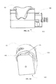
- FIG. 7 depicts one embodiment of a U-shaped blank having a backing plate adapted for tool fixturing
- FIG. 8 depicts a perspective view of the U-shaped blank of FIG. 7 with an attached 3R macro chuck
- FIG. 9 depicts a perspective view of one embodiment of a patient-adapted implant machined out of the U-shaped blank of FIG. 8 ;
- FIG. 10 depicts the top view of one embodiment of a patient-adapted fixture
- FIG. 10A depicts a bottom view of the patient-adapted fixture of FIG. 10 ;
- FIG. 11 depicts a side view of the patient-adapted fixture of FIG. 10 ;
- FIG. 12 depicts a side view of a patient-adapted fixture and implant
- FIG. 13 depicts an opposing side view of the patient-adapted fixture and implant of FIG. 12 ;
- FIG. 14 depicts a side view or “end-on” view of the patient-adapted fixture and implant of FIG. 12 ;
- FIG. 15 depicts a perspective view of patient-adapted implants and fixtures connected to a drag-finishing apparatus
- FIG. 16 depicts a perspective view of patient-adapted implants and fixtures connected to a drag-finishing apparatus
- FIG. 17 depicts a cross-sectional view of one embodiment of an asymmetric “W” shaped blank
- FIG. 18 depicts a cross-sectional view of an asymmetric “moon” shaped blank
- FIG. 19 depicts a view of an unfinished articulating surface of a patient-adapted implant casting
- FIG. 20 depicts various bone contacting surfaces of the patient-adapted implant casting of FIG. 19 ;
- FIG. 21 depicts a top view of a machined aluminum “patient-appropriate” fixture
- FIG. 22 depicts the front view of a patient-adapted femoral bone fixture docked with a partially-machined patient-adapted implant attached to a macro chuck;
- FIG. 23 depicts a side view of the patient-adapted femoral bone fixture showing one ideal fit of the patient-adapted implant
- FIG. 24 depicts the top view of a patient-adapted femoral bone fixture
- FIG. 25 depicts the bottom view of FIG. 24 showing the collet insertion holes
- patient-adapted implants e.g., patient-specific and/or patient-engineered implants and associated surgical procedures, many of which relate to the amount of time required to manufacture the implant, as well as the significant costs associated with creating a unique implant for each individual surgical patient.
- patient-adapted implants are generally created after a patient has been identified as a surgical candidate, and the implant is designed and/or selected using imaging data taken of the intended patient's anatomy.
- the process of designing, manufacturing and finishing the implant can involve a number of steps, typically involving multiple vendors, and this process must result in an acceptable implant before the surgery can occur.
- the creation of a patient-adapted implant from patient imaging data can require more than 4 to 7 weeks, which is a significant delay for both the surgeon and the patient.
- An additional concern relating to the use of patient-adapted implants relates to the availability of processing and manufacturing equipment, as well as the assurance that the implant components will be processed and available for the surgical procedure. Because each patient-adapted implant is unique, and because a significant amount of time and effort is required to create each implant, it is typical practice to manufacture multiple copies (e.g., a primary and a backup implant) of an implant for a single patient, to ensure that at least one implant survives the manufacturing, finishing and testing processes prior to surgical use. However, because such backup implants are only needed where the primary implant has failed, the constant creation of backup implants leads to unused inventory and unnecessary costs where the primary implant does not get damaged.
- “blanks” refers to a piece of material (e.g., metal, plastic) from which all, or at least a portion, of an implant may be formed through various manufacturing/processing techniques, such as, for example, those techniques discussed below.
- a blank may be selected, designed, and/or manufactured with at least a portion that is patient adapted and/or patient appropriate (i.e., appropriate or suitable for forming into a range of differing patient-adapted implants through various manufacturing/processing techniques).
- the terms “blank,” “implant,” and also “casting” are interchangeably used herein to refer to such a piece of material, in the context of any of the various stages during which such a piece of material is being manufactured/processed from a blank to a finished implant, which requires no more processing for use in a surgical procedure.
- blanks may be rapidly manufactured or otherwise modified into suitable patient-adapted implant replacements in the event a primary implant cannot be manufactured in a desired amount of time, at a desired cost, or for various other reasons, including where such primary implants are damaged or fail at various points along the manufacturing process.
- the capability to create such patient-adapted back-up implants can reduce and/or obviate the need to pre-order multiple copies of an individual patient-adapted implant design to account for failed and/or damaged primary implants.
- the blank-manufacturing and/or modification process involves a significant increase in the cost of creating an individual patient-adapted implant (such as, for example, as compared to the cost of manufacturing each individual backup implant copy using standard methods), the overall reduction in implant duplication and wastage may result in significant cost savings.
- a femoral implant component may cost approximately $1000 per copy to manufacture using standard casting and machining techniques, with the manufacturing process having a 95% acceptance rate. For 1000 surgeries, this would mean ordering 2000 implants (a primary and a backup implant for each surgery) at a cost of $2 million. At the standard acceptance rate, this would mean that approximately 950 primary implants would be acceptable, with approximately 50 surgeries requiring a backup implant. The unused backup implants would thus constitute 950 backup implants, which were created at a cost of $950,000 (and these implants would now be scrapped). Much of this amount could potentially be saved by using various of the methods and embodiments described herein.
- the use of blanks and blank-processing methods would obviate the need for the backup implant (at a cost reduction of approximately $1,000,000 for the 1000 backup implants) and, even if the currently disclosed blank manufacturing and modification process cost $5000 per backup implant to accomplish (for a cost of $250,000 for 50 backup implants), an overall savings of $750,000 in manufacturing expense could be realized.
- a 95% acceptance rate for implants would not only mean that 95% of the primary implants (950 of 1000) would be acceptable, but also that 95% of the backup implants would be acceptable (or that there would be a 5% failure rate for all implants, including the backups). For 50 backup implants, this could mean that at least two (actually a probability estimate of 2.5) of the backup implants would also fail, leaving no implants (primary or backup) available for surgery. In contrast, the use of blanks would allow creation of one or more additional backup implant components, no matter how many failures are encountered, thereby allowing the surgery to move forward as scheduled.
- the described methods can include a comparison or processing step in which, prior to ordering or creating a patient-adapted implant design (such as from a manufacturer and/or 3rd party vendor), the proposed implant design is compared to a selection of one or more blanks (e.g., physical blanks or electronic blank designs) to determine if a backup implant can be created out of an available blank using one or more available manufacturing techniques. If such manufacture is possible, then only a single implant (or whatever number is minimally necessary to accomplish the surgery) is ordered from the vendor/manufacturer.
- a patient-adapted implant design such as from a manufacturer and/or 3rd party vendor
- both a primary and backup implant can be ordered for that specific patient.
- a backup implant may be created from a blank on an as-needed basis or using “just-in-time” manufacturing principles by utilizing precursor patient-adapted or patient-appropriate blanks. Creating patient-adapted blanks may reduce manufacturing time of a backup implant when a fracture, failure or sufficient discrepancy in the manufacturing process requires immediate replacement of the primary implant.
- the use of blank-manufacturing techniques may also allow expedited production of patient-adapted primary implants, such as, for example, where an implant is needed for emergency surgery to address high-velocity fractures or other trauma, etc.
- Patient-adapted blanks may be designed and/or created as patient-appropriate, partially customized, or fully customized.
- patient-appropriate blanks can include generally standard or generic blanks with a range of shapes and sizes.
- the size and shape of particular designs of patient-appropriate blanks may be based on features and/or dimensions common to a class of patient-adapted implants that can be formed from the patient-appropriate blanks of the particular design.
- Various standard, anatomical patient databases or patient image data can be used to select specific features, dimensions, and/or thicknesses to design and/or create specified portions of the patient-appropriate blanks.
- such specific features/dimensions may include, but are not limited to, anterior/posterior cut distance, intercondylar notch width, presence of integral pegs, position/orientation of pegs, and thickness of implant.
- a particular patient-appropriate blank design may have a shape that accommodates formation of integral pegs, and accordingly, the particular design could be appropriate for manufacturing a class of patient-adapted implants that all include integral pegs.
- a particular patient-appropriate blank design may have a size with dimensions that are equal to or larger than corresponding dimensions of a class of patient-adapted implants, and accordingly, the particular design could be appropriate for manufacturing patient-adapted implants of that class. Exemplary embodiments of various blanks that can be patient-appropriate are described in greater detail below. If desired, various designs of patient-adapted blanks may be maintained in inventory, with the most commonly used blanks maintained in higher quantities.
- a patient-adapted blank may be designed and/or created as partially customized or fully customized. For example, one or more features and/or dimensions of a blank may be customized based on information from patient-specific image data.
- Blanks may be created by casting, forging, rolling or other processes (including combinations of processes) known in the art. Casting may be performed using standard casting procedures for the blanks. Various forging techniques and methods may be used, such as GFM, closed die forging, firth rixson forging, and/or press forging. Likewise, various rolling processes may be used, such as ring rolling, roll bending, roll forming, profile rolling, and controlled rolling. Depending upon the manufacturing process selected, the patient-adapted blank may have varying material properties and durability. In some embodiments, a forged or wrought material may be desirous, while in others, a cast material may have advantageous qualities.
- patient-appropriate blanks of several standard or generic sizes may be available in inventory. Should damage or failure of a patient-adapted implant casting occur during manufacturing process, such as, for example, machining, buffing, or polishing, a patient-adapted blank may be recommended or selected from the available inventory.
- software may be configured to utilize a CAD design file created from patient image data to compare the specific dimensions and features of the patient anatomy to the available standard or generic sizes stored in inventory. The software may provide a printout of a recommended size and automatically deduct the size from the inventory database (or may place a “hold” on the blank or other inventory management feature known in the art until acceptance of the finished primary implant is established).
- the software can be programmed to recommend and/or select various alternative options should a recommended size be unavailable, such as, for example, by ordering a backup implant to be casted or machined directly from a wrought ingot, or by choosing an alternative blank design that, although suboptimal in some manner, may be used to create the implant.
- the software may also identify the time to manufacture, cost and availability to help a technician select the best option to replace the primary patient-adapted implant.
- the dimensions and/or material properties of the blank may be considered in altering or otherwise modifying the intended blank design, such as where an increased material strength of the blank allows for a thinner implant, or where a blank of desired dimensions is not available, but an acceptable blank can be manufactured for use which requires alterations to the intended surgical plan and/or surgical tools.
- various features of the blank and/or the comparison process may alter the intended design, surgical procedure and/or tools utilized therein.
- an initially chosen (or highly-rated) design for a patient-adapted implant may be altered or rated lower if the intended design has no readily-available blank for creating a backup implant, while an alternate intended design that is “less-acceptable” for one or more reasons (as compared to the other design) does have a blank available for creating a backup.
- Various embodiments described herein may utilize patient-adapted blanks stored in inventory to increase the availability and/or accuracy of the manufactured patient-adapted implants.
- the patient-adapted implant may already be manufactured and stored in inventory or shipped to the hospital for the next scheduled surgery date.
- the surgical date has been significantly extended, or where the patient's anatomy has changed for any reason (e.g., the patient experiences a high velocity knee fracture from a vehicle accident, etc.)
- the patient joint anatomy may change or may be affected by other external factors.
- the patient may require a new implant to be manufactured and the previously manufactured implant to be scrapped.
- This issue can be resolved by submitting the new patient image data, comparing the patient image data to the available patient-adapted blank inventory, and selecting the appropriate blank to create the new patient-adapted implant. In such a case, the patient may not have to wait an additional 4 to 7 weeks for a new implant to be created.
- a patient-adapted implant can be created from the blank through various manufacturing processes, including, for example by using a 4D or 5D machining process.
- the 4D or 5D machining process can include the use of multiple processing machines, including multiple software programs and/or machine tool controllers, to machine, for example, in the case of a knee implant, the femoral contact surface and the articulating surface.
- the various surfaces of the blank can be machined and/or finished in a single operation or in multiple machining operations.
- blank-specific, implant-specific, and/or patient-adapted fixtures and/or tooling may be designed, selected and/or created to facilitate the manufacturing process.
- a fixture may allow the blank to be attached to multiple milling machines and/or other processing apparatuses without requiring re-registration of the blank with respect to each apparatus.
- Various embodiments may include designing the blank and/or fixture(s) to connect directly to processing apparatuses (e.g., 4D or 5D mill machine) or to connect by an intermediary, such as, for example, a macro chuck.
- processing apparatuses e.g., 4D or 5D mill machine
- an intermediary such as, for example, a macro chuck.
- a software program may be loaded into an individual machine with patient-specific implant information that facilitates machining and/or further processing of the patient-adapted blank and/or implant.
- the implant may undergo additional or further processing.
- the implant can be buffed, polished and/or cleaned using a variety of standard methods prior to implantation.
- the implant will then be inspected, packaged and shipped to the appropriate hospital for the scheduled surgery.
- the use of blanks in creating patient-adapted implants can facilitate machining and processing, at least in part, by reducing the amount of material that must milled, drilled, cut and/or otherwise removed from the starting material form.
- a desired implant can be created in significantly reduced time, and with significantly reduced effort, as compared to a traditional ingot.
- FIG. 1 depicts one embodiment of a Y-shaped patient-appropriate implant blank 5 for use in creating a patient-adapted femoral implant.
- the body 25 may have varying widths and heights, depending upon the amount of variation in the final patient-adapted design the blank is desired to accommodate.
- a larger body may be capable of accommodating a larger variation in implant sizes, but will also incorporate a larger amount of material that will typically have to be removed to create a given implant.
- the height of the body can be designed/selected to incorporate sufficient material to accommodate the formation of various peg heights and/or locations in the implant, or the height can be designed/selected thinner if the use of attachable pegs (e.g., drilled and taped pegs) is contemplated and/or acceptable.
- the blank may have symmetric medial and/or lateral side walls 15 , which can accommodate various orientations (including reversed orientations) of a desired implant design, to accommodate patient anatomy as well as to aid in manufacturing.
- the blank may have a centered rib 20 on a bottom surface for fixation to a vise, collet or equivalent machine fixation method.
- the blank may incorporate radiused edges 10 for various purposes, including ease of machining, for technician handling and/or for casting purposes.
- FIG. 2 depicts the top view of another embodiment of a patient-adapted blank.
- a thinner side wall 30 and thicker side wall 35 may accommodate significant variation in accommodated patient-adapted implant design, as various designs may require, for example, differing material widths for anterior and posterior portions of the implant.
- an anterior section of a femoral implant design may require a thicker side wall (e.g., an anterior portion may be thicker or more angled relative to the remainder of the implant), while a posterior portion requires less sidewall thickness.
- a posterior section of another femoral implant design might require a thicker side wall, while an anterior portion requires less sidewall thickness.
- the thicker side wall 35 could potentially accommodate an implant having condylar portions that accommodate asymmetric bone cuts (e.g., posterior bone cuts separated by a chamfer cut), while the thinner side wall 30 could accommodate a condylar portion for use with a single planar cut.
- Such side walls of differing thicknesses could, therefore, potentially accommodate a wider range of implant designs than side walls of the same thickness.
- the bone contacting surface 40 of the blank may be designed with varying widths and lengths to accommodate offset peg locations or large diameter pegs.
- FIG. 3 is a perspective view of an embodiment of a W-shaped patient-appropriate blank.
- the grooves 45 in this blank may include radiused edges to accommodate patient anatomy and/or ease of manufacturability or for various other reasons.
- Some embodiments can further include a central rail 50 , which may be rectangular, square or any other appropriate shape along the length of the implant. In the embodiment shown in FIG. 3 , the height of the body is reduced, while the height of the rail 50 allows for machining of one or more anchoring posts for anchoring of the implant to the underlying bony anatomy.
- FIG. 4 is a front view of a W-shaped blank embodiment.
- a central rib 55 can be used to mate, connect or otherwise attach the blank to a vise or other processing machinery.
- the rib 55 can be designed with varying widths or heights to accommodate different types of vises and/or commercially-available machining equipment.
- the grooves may also be designed with chamfers 60 instead of radiused or square edges.
- FIG. 5 is a top view of a W-shaped blank embodiment.
- Rail 65 may be designed with a variety of thicknesses to accommodate larger diameter pegs or offset pegs. In some embodiments, the rail 65 does not run continuous throughout the length of the blank. For example, in some embodiments, the rail 65 may be configured as two separate rails, leaving a flat surface in the center. The rail 65 may also be designed to be offset, such as, for example, with the medial groove 75 and the lateral groove 70 having differing widths and/or heights.
- FIG. 6 depicts a side view of a W-shaped blank having a cylindrical rod 80 , which can be configured to attach to a variety of collet sizes and/or shapes for a mill machine or other machines that require and/or utilize collets for attachment purposes.
- some embodiments may include a Y-shaped blank having a similar connection cylinder.
- FIG. 7 depicts a perspective view of a patient-appropriate blank incorporating a backing plate 85 to accommodate connection to tool fixtures.
- the backing plate may be used to attach to variety of mechanisms for machining purposes or other machines for further processing.
- FIG. 8 depicts a perspective view of the patient-appropriate blank and backing plate of FIG. 7 attached to a 3R macro chuck 90 .
- the macro chuck may be attached to the appropriate milling machine to stabilize the blank while undergoing the implant machining process.
- FIG. 9 depicts a perspective view of an embodiment of a patient-adapted implant 93 created from the patient-appropriate blank of FIG. 8 .
- the 3R macro chuck 90 is secured to the backing plate 85 to rigidly secure the blank during the machining of the patient-adapted implant 93 .
- the patient-adapted implant may desirably remain attached to the backing plate 85 by one or more connection tabs 87 , which can be subsequently removed from the backing plate 85 by mechanical means, such as cutting, sawing, bending, etc.
- the connections can be located on outer articulating and/or sidewall faces of the implant, although virtually any location on the implant consistent with the present disclosure can be utilized.
- Various embodiments described herein include the use of patient-adapted fixtures during various portions of manufacturing/processing.
- at least a portion of the blank has been machined or otherwise processed to create one or more patient-adapted surfaces on the implant, while some remaining portion of the blank has not been machined or processed into a final patient-adapted shape.
- This remaining portion may include some or all of a portion of the blank that connects the machined portion to the machining and/or processing apparatuses already used.
- a patient-adapted fixture which corresponds to one or more of the patient-adapted surfaces (e.g., surfaces already machined) of the blank, can be engaged and attached to the blank at the corresponding location(s), connection(s) to any machining/processing apparatus can be released or otherwise severed or removed, and the blank can be secured by the fixture while some or all of the remainder of the blank is machined and/or otherwise processed to complete the production of the patient-adapted implant (including portions that were connected to any machining/processing apparatus).
- the patient-adapted fixture can include known dimensions, sizes and/or orientations for itself, as well as the blank it secures, and this information can be utilized by subsequent machinery, measuring and/or processing equipment in further machining, processing, finishing and/or inspection of the patient-adapted implant.
- FIG. 9 a blank has been machined such that a bone-facing surface 95 of the patient-adapted implant 93 is in a final form for implantation and, optionally, much of the articulating surface of the implant has been initially machined. At least a portion of a connection tab 87 of the implant remains connected to the backing plate 85 of the blank. In addition much of the articulating surface (not shown) will require additional smoothing, processing and/or polishing prior to implantation.
- FIG. 10 depicts a top view of a patient-adapted fixture 103 created to hold and secure the patient-adapted implant of FIG.
- the fixture can include a plurality of holes (two, in the figure) that may be of equal or unequal diameters, shapes and/or alignments to accommodate one or more pegs of the patient-adapted blank/implant.
- a first hole 105 can be designed to have a fixed location and/or orientation on the fixture relative to a connection device 100 , which may be configured to be secured to connecting surface of fixture 103 . This fixed location can allow the CAD design file and/or the automated machinery to calibrate a starting position and/or implant location and/or orientation for initiation of the machining process.
- the fixture can include a first datum edge 102 , a second datum edge 101 and/or an axial position concentric with the first hole 105 .
- the first hole 105 may be the same or of a smaller or larger diameter than the second hole 115 .
- the second hole 115 may be designed to have varying locations based on the specific patient's anatomy. The location of the second hole may be different for each patient-adapted implant. Also, the second hole 115 may be designed to have a larger diameter than the first hole 105 to accommodate small diameter adjustments, variances and/or inaccuracies of the distance between the two pegs.
- the mating surface 110 may be designed to seat the bone contacting surface of the patient-adapted implant. The mating surface 110 may have a flat mating surface or it may be angled for the best fit. Moreover, the holes may be designed to extend completely through the height of the fixture and tapered to fit a small collet.
- FIG. 10A depicts a close-up top view of another embodiment of a patient-adapted fixture.
- the figure illustrates a first reduced diameter hole 118 in a first hole 119 on the mating surface, and second reduced diameter hole 117 in a second hole 116 on the mating surface.
- the reduced diameter holes 118 , 117 may be designed with a step-down diameter reduction rather than a tapered hole. This step-down diameter reduction from second hole 116 on the mating surface to the second reduced diameter hole 117 can allow a collet assembly to have a positive stop or provide positive feedback to the technician to stop retracting the collet assembly further.
- the shelf on the collet can be retracted slowly when placed concentrically in the first 119 and second 116 hole until the collet assembly stops. This may ease manufacturing procedures by eliminating a need for constant measuring and reducing potential damage to the implant.
- FIG. 11 depicts the side view of one patient-adapted fixture embodiment incorporating medial and lateral placement surfaces.
- the medial placement surface 125 and lateral placement surface 120 are surfaces desirably formed to be patient-adapted and correspond to the inner, bone-facing surfaces of the patient-adapted surfaces already created on a blank.
- the placement surfaces are of different heights and slightly offset, which corresponds to the slightly offset bone-contacting surfaces of the implant.
- the holes and placements are specifically designed and positioned to ensure that the implant cannot be secured to the fixture in a reverse orientation (i.e., the implant cannot be secured to the fixture in both a forward and 180 degree reverse orientation), thereby eliminating manufacturing errors due to misaligning the implant backwards on the fixture.
- the fixture desirable secures the implant in a known position/orientation relative to a connector 100 secured to the fixture.
- FIGS. 12, 13, and 14 depict a patient-adapted implant 93 seated on the patient-adapted fixture 103 , with the bone-facing surfaces of the implant being desirably flush with the medial and lateral placement surfaces.
- the posts of the implant are desirably inserted into the first and second holes of the fixture, and the implant is secured to the fixture via collets, which secures the implant in a known orientation and position relative to the fixture.
- the fixture is secured to a connector 100 (e.g., a chuck) for further attachment to one or more processing apparatuses.
- the processing apparatus can be programmed with the desired patient-adapted implant shape file, and can utilize various processing methods (e.g., machining, milling, cutting, warping, drilling, smoothing, shaping, finishing, buffing, polishing, cleaning, inspecting, drag finishing) to prepare the articulating surface of the implant.
- processing methods e.g., machining, milling, cutting, warping, drilling, smoothing, shaping, finishing, buffing, polishing, cleaning, inspecting, drag finishing
- the connector 100 may be released from one machine, and moved to another, with the known relationship between the connector, fixture and implant allowing subsequent equipment to process the patient-adapted implant without requiring additional “set-up” time.
- the fixture may have first 140 and second 130 edges that are chamfered (as shown in FIG. 14 ) or radiused edges and that may accurately fit the implant.
- both first 140 and second 130 edges may be symmetrical in dimensions, while in other embodiments they may also be designed to have different angles or widths to mimic the resection cuts from the bone contacting surface of the patient-adapted implant.
- the mating surface 135 may be flat or have a specified angle to accommodate the bone contacting surface of the implant.
- patient-adapted fixture 103 may facilitate securing patient-adapted implant 93 in various processing apparatuses.
- a drag finishing machine can be one example of such a processing apparatus.
- one or more patient-adapted implants 93 a - c may each be secured to a patient-adapted fixture 103 a - c , respectively, and each of the patient-adapted fixtures 103 a - c may be connected via connectors 100 to spindles 141 of a drag-finishing drive unit 142 .
- the drag finishing drive unit 142 may then be controlled to drag the patient-adapted implants 93 a - c through a bed of mass finishing media.
- the drag-finishing drive unit may be rotated, and likewise, each of the spindles 141 may be rotated and/or rotate the respective patient adapted fixtures 103 a - c .
- the engagement surfaces of the patient-adapted fixtures 103 a - c may abut substantially the entirety of the bone-facing surfaces of the respective patient-adapted implants 93 a - c .
- Drag finishing may be used for, for example, surface grinding, deburring, edge breaking and radiusing, and/or surface smoothing (e.g., smoothing an articulating surface of an implant).
- FIG. 17 depicts a cross-sectional view of one embodiment of an asymmetric W-shaped blank.
- This blank may be created by rolling, casting or forging, and can also be formed out of an elongated wrought ingot.
- the first side 145 of the asymmetric embodiment may be designed to have a longer or taller height than the second side 150 .
- the first and second sides may have any type of edge that will accommodate further machining, including, for example, radiused, beveled or flat edges.
- the asymmetric blank may also have a rail 155 to assist with the machining of the pegs.
- the rail 155 may be of various widths and/or heights to accommodate the changing anatomy of the patients.
- the rail 155 may also be removed to have an asymmetric “U” shaped embodiment.
- FIG. 18 depicts a front view of a “moon” shaped blank embodiment.
- This asymmetric blank may be created by rolling, casting or forging. Also, the device manufacturer may also consider to make this asymmetric profile of a wrought ingot.
- the bone-facing surface 160 may have different concavity dimensions.
- the width 165 may also vary with the patient anatomy.
- the first side 170 may be designed to a different height with radiused edges.
- FIG. 19 depicts the articulating surface view of one embodiment of a patient-adapted implant, which may be created as part of a primary implant order.
- This casting can include a patient-adapted bone-facing surface (not shown) with a joint-facing surface of the implant that may require some additional machining and/or processing, including, for example, the removal of gates 180 and 180 and/or vent holes 177 from the implant.
- the casting may undergo a variety of processes to remove the gates, including removal by milling, machining, buffing, and/or polishing.
- Further processing for the articulating surface can include milling, machining, buffing, drag-finishing, and/or polishing of the articulating surface (as well as, optionally, any additional surfaces) to desired shapes, sizes, thicknesses and/or surface finishes.
- a patient-adapted fixture can be utilized with, for example, the implant of FIG. 19 to accomplish various processing steps, including the removal of cast gates, vents and/or connections (or other remaining unnecessary and/or unwanted materials and/or artifacts on an implant and/or implant blank), and processing of unfinished surfaces of the implant.
- processing steps including the removal of cast gates, vents and/or connections (or other remaining unnecessary and/or unwanted materials and/or artifacts on an implant and/or implant blank), and processing of unfinished surfaces of the implant.
- a patient-adapted fixture appropriate to the bone-facing surfaces can be designed and/or selected, and the implant secured to the fixture.
- the implant which will have a known location and orientation relative to the fixture (which in turn can have a known location and orientation relative to some other reference point, such as an attached collet or chuck) can then be connected, directly or indirectly (e.g., by means of one or more intermediary connectors) to various processing apparatuses, which may, for example, incorporate software and/or patient-specific data suitable, for further processing of the implant, including machining, milling, cutting, warping, drilling, smoothing, shaping, finishing, buffing, polishing, cleaning, inspecting, drag finishing, etc.
- the fixture can be moved between various machines and/or measuring instruments, with the known relationship between the fixture and the implant service to quickly register the implant location/orientation relative to the programmed patient-specific data.
- FIG. 20 depicts the bone-facing surface of an unfinished patient-adapted implant.
- the implant includes medial and lateral side indicia 185 and 190 , which desirably simplifies placement of the implant on the fixtures and ensures accurate alignment.
- the pegs 195 and bone-facing surfaces are unfinished and/or porous to desirably increase attachment to the underlying bone surface.
- the pegs 195 may be shaped in a “cross” or “plus” design to facilitate cement interdigitation through the small channels of the pegs 195 .
- the pegs 195 may be designed into the forged, rolled or casted blank, or may be separate structures secured to the implant at a later time by drilling and tapping the hole for a screw thread attachment.
- FIG. 21 depicts an embodiment of a patient-adapted fixture, which may be constructed out of a metallic material such as, for example, aluminum or brass.
- This embodiment includes a first hole 196 and a second hole 197 for engaging the implant (such as the implant shown in FIG. 20 ) to the fixture.
- the engagement (i.e., implant-contacting) surfaces of the fixture can correspond to various bone-facing surfaces of a patient-adapted implant requiring further processing as described herein.
- the fixture can further include one or more step cuts 198 between adjacent medial and lateral surfaces that can accommodate implants having different height distal cuts on medial and lateral bone-facing surfaces.
- the implant-contacting surfaces of the fixture can correspond to some portion, or optionally all, of the bone-facing surfaces of the implant.
- the fixture of FIG. 21 incorporates two upper surfaces separated by a vertical step cut 198 .
- the inner surfaces of the implant of FIG. 20 includes two inner surfaces separated by an angled or tapered step cut 199 , which does not precisely correspond to the vertical step cut 198 of the fixture.
- the fixture may still adequately accommodate the implant of FIG. 20 , even though the entirety of the surface of the fixture is not patient-adapted.
- engagement surfaces of the fixture may be used to assess the fit of the bone-facing surfaces of the blank.
- the engagement surfaces of the fixture may be engaged (e.g., placed in contact) with the bone-facing surfaces of the implant blank, to determine if the bone-facing surfaces have been completely and properly machined and/or otherwise processed. If the fit is poor, and the fixture cannot be placed in sufficient contact with bone-facing surfaces of the implant blank, this fact may indicate that the bone-facing surface of the implant blank has not yet been completely and properly machined and/or otherwise processed. Because the implant blank has not yet been separated or otherwise detached from the equipment, the equipment can be utilized to continue the machining process.
- the partially-machined implant blank may be removed from processing equipment and/or any connections (such as, for example, connections to the backing plate) can be separated.
- the implant blank may then be connected to the same or a different patient-adapted fixture and further processed, as described herein.
- FIG. 24 depicts a top view of a patient-adapted femoral bone fixture incorporating proposed medial 235 and lateral 240 condylar resection cuts.
- a femoral bone fixture may be created and/or designed to be fully or partially patient-adapted, and the outer surfaces of the fixture can reflect one or more of the intended surgical resection cuts, the intended inner bone-facing surfaces of the implant and/or varying combinations thereof.
- the image data gathered from each patient to create the CAD design file can be used to create the femoral bone fixtures, or data defining the inner surfaces of the implant can be used. For example, in the embodiment shown in FIG.
- the patient image data was used to provide the dimensions of the medial 235 condyle resected cuts, the lateral 240 condyle resected cuts, and the condylar notch 245 width.
- the femoral bone fixture may be created using three-dimensional polymer printing techniques, or other three-dimensional printing techniques known in the art, or can be machined out of various materials using standard techniques.
- the CAD design file with the patient-specific image data can be sent to a 3rd party vendor to manufacture the femoral bone fixtures using standard ULA process, plastics or a variety of metals.
- the femoral bone fixture may comprise a patient-adapted fixture for securing the implant blank for further processing, as described herein.
- a patient-adapted fixture may comprise a femoral bone fixture which verifies that desired machining (and/or other processing steps) have been completed on various blank surfaces prior to removal and/or detachment from machining equipment.
- FIG. 22 depicts a front view of a patient-adapted femoral bone fixture 200 positioned in contact with a machined patient-adapted implant 205 attached to a macro chuck 210 via post 215 .
- the manufacturer may use the patient-adapted femoral bone fixture 200 to assess the bone-facing surface of the patient-adapted implant 205 prior to removing the implant from the macro chuck 210 . Such inspection may require the manufacturer to pause or stop the 4D or 5D mill machine after it has machined the bone-facing surface of the patient-adapted implant 205 or wait until the mill machine has completely finished machining the implant.
- the manufacturer can attempt to align the femoral bone fixture 200 within the bone contacting surface of the implant 205 to ensure that dimensions are accurate. If the manufacturer has difficulty aligning the femoral bone fixture 200 with the implant 205 , this fact may indicate a need for further inspection of the implant, equipment and/or the femoral bone fixture.
- the implant 205 may require adjustment of the CAD design file or other changes/alterations to accommodate the femoral bone fixture 200 .
- the mill machine will make the dimensional adjustments to the implant 205 and the manufacturer may re-inspect with the femoral bone fixture 200 . This process may be repeated in an iterative fashion, until the implant 205 passes the inspection.
- the patient-adapted implant 205 may be detached from the face plate 220 by removing the material tab 215 (e.g., by cutting, sawing, bending, and/or machining the tab 215 off).
- FIG. 23 depicts a side view of an ideal fit and alignment of a patient-adapted femoral bone fixture 230 with a patient-adapted implant 225 .
- the implant may undergo further processing (e.g., machining, milling, cutting, warping, drilling, smoothing, shaping, finishing, buffing, polishing, cleaning, inspecting, drag finishing).
- the femoral bone fixture 230 may be used again after the further processing to ensure that the further processing did not affect the dimensions of the patient-adapted implant 225 .
- FIG. 25 depicts the bottom view of a patient-adapted femoral bone fixture showing medial and lateral holes 255 and 250 .
- the manufacture may decide to create or design the femoral bone fixture to be “free-floating,” or the fixture can attach to the bone-facing surfaces of the implant using a collet or other assembly. The manufacturer may then decide to conduct further processing on the implant supported on the femoral bone fixture.
Abstract
Description
Claims (10)
Priority Applications (4)
| Application Number | Priority Date | Filing Date | Title |
|---|---|---|---|
| US13/746,742 US9408686B1 (en) | 2012-01-20 | 2013-01-22 | Devices, systems and methods for manufacturing orthopedic implants |
| US15/226,370 US10456261B2 (en) | 2012-01-20 | 2016-08-02 | Devices, systems and methods for manufacturing orthopedic implants |
| US16/660,362 US11419726B2 (en) | 2012-01-20 | 2019-10-22 | Systems and methods for manufacturing, preparation and use of blanks in orthopedic implants |
| US17/893,898 US20220401222A1 (en) | 2012-01-20 | 2022-08-23 | Systems and Methods for Manufacturing, Preparation and Use of Blanks in Orthopedic Implants |
Applications Claiming Priority (2)
| Application Number | Priority Date | Filing Date | Title |
|---|---|---|---|
| US201261589163P | 2012-01-20 | 2012-01-20 | |
| US13/746,742 US9408686B1 (en) | 2012-01-20 | 2013-01-22 | Devices, systems and methods for manufacturing orthopedic implants |
Related Child Applications (1)
| Application Number | Title | Priority Date | Filing Date |
|---|---|---|---|
| US15/226,370 Division US10456261B2 (en) | 2012-01-20 | 2016-08-02 | Devices, systems and methods for manufacturing orthopedic implants |
Publications (1)
| Publication Number | Publication Date |
|---|---|
| US9408686B1 true US9408686B1 (en) | 2016-08-09 |
Family
ID=56556725
Family Applications (4)
| Application Number | Title | Priority Date | Filing Date |
|---|---|---|---|
| US13/746,742 Active 2034-02-02 US9408686B1 (en) | 2012-01-20 | 2013-01-22 | Devices, systems and methods for manufacturing orthopedic implants |
| US15/226,370 Expired - Fee Related US10456261B2 (en) | 2012-01-20 | 2016-08-02 | Devices, systems and methods for manufacturing orthopedic implants |
| US16/660,362 Active US11419726B2 (en) | 2012-01-20 | 2019-10-22 | Systems and methods for manufacturing, preparation and use of blanks in orthopedic implants |
| US17/893,898 Abandoned US20220401222A1 (en) | 2012-01-20 | 2022-08-23 | Systems and Methods for Manufacturing, Preparation and Use of Blanks in Orthopedic Implants |
Family Applications After (3)
| Application Number | Title | Priority Date | Filing Date |
|---|---|---|---|
| US15/226,370 Expired - Fee Related US10456261B2 (en) | 2012-01-20 | 2016-08-02 | Devices, systems and methods for manufacturing orthopedic implants |
| US16/660,362 Active US11419726B2 (en) | 2012-01-20 | 2019-10-22 | Systems and methods for manufacturing, preparation and use of blanks in orthopedic implants |
| US17/893,898 Abandoned US20220401222A1 (en) | 2012-01-20 | 2022-08-23 | Systems and Methods for Manufacturing, Preparation and Use of Blanks in Orthopedic Implants |
Country Status (1)
| Country | Link |
|---|---|
| US (4) | US9408686B1 (en) |
Cited By (16)
| Publication number | Priority date | Publication date | Assignee | Title |
|---|---|---|---|---|
| US9700971B2 (en) | 2001-05-25 | 2017-07-11 | Conformis, Inc. | Implant device and method for manufacture |
| US9849019B2 (en) | 2012-09-21 | 2017-12-26 | Conformis, Inc. | Methods and systems for optimizing design and manufacture of implant components using solid freeform fabrication |
| US10405993B2 (en) | 2013-11-13 | 2019-09-10 | Tornier Sas | Shoulder patient specific instrument |
| US10456261B2 (en) | 2012-01-20 | 2019-10-29 | Conformis, Inc. | Devices, systems and methods for manufacturing orthopedic implants |
| US10485676B2 (en) | 2012-09-20 | 2019-11-26 | Conformis, Inc. | Solid freeform fabrication of implant components |
| US10716676B2 (en) | 2008-06-20 | 2020-07-21 | Tornier Sas | Method for modeling a glenoid surface of a scapula, apparatus for implanting a glenoid component of a shoulder prosthesis, and method for producing such a component |
| US10959742B2 (en) | 2017-07-11 | 2021-03-30 | Tornier, Inc. | Patient specific humeral cutting guides |
| US10987176B2 (en) | 2018-06-19 | 2021-04-27 | Tornier, Inc. | Virtual guidance for orthopedic surgical procedures |
| US11065016B2 (en) | 2015-12-16 | 2021-07-20 | Howmedica Osteonics Corp. | Patient specific instruments and methods for joint prosthesis |
| US11166733B2 (en) | 2017-07-11 | 2021-11-09 | Howmedica Osteonics Corp. | Guides and instruments for improving accuracy of glenoid implant placement |
| US11324525B1 (en) | 2021-06-30 | 2022-05-10 | Kinos Medical Inc. | Surgical alignment guide assembly for total ankle replacement and method of using the same |
| US11376054B2 (en) | 2018-04-17 | 2022-07-05 | Stryker European Operations Limited | On-demand implant customization in a surgical setting |
| US11806028B1 (en) | 2022-10-04 | 2023-11-07 | Restor3D, Inc. | Surgical guides and processes for producing and using the same |
| USD1013875S1 (en) | 2020-01-08 | 2024-02-06 | Restor3D, Inc. | Spinal implant |
| USD1013876S1 (en) | 2020-01-08 | 2024-02-06 | Restor3D, Inc. | Osteotomy wedge |
| US11960266B1 (en) | 2023-08-23 | 2024-04-16 | Restor3D, Inc. | Patient-specific medical devices and additive manufacturing processes for producing the same |
Citations (176)
| Publication number | Priority date | Publication date | Assignee | Title |
|---|---|---|---|---|
| US4673409A (en) | 1984-04-25 | 1987-06-16 | Minnesota Mining And Manufacturing Company | Implant with attachment surface |
| US4822365A (en) | 1986-05-30 | 1989-04-18 | Walker Peter S | Method of design of human joint prosthesis |
| US4841975A (en) | 1987-04-15 | 1989-06-27 | Cemax, Inc. | Preoperative planning of bone cuts and joint replacement using radiant energy scan imaging |
| US4936862A (en) | 1986-05-30 | 1990-06-26 | Walker Peter S | Method of designing and manufacturing a human joint prosthesis |
| US5007936A (en) | 1988-02-18 | 1991-04-16 | Cemax, Inc. | Surgical method for hip joint replacement |
| DE3933459A1 (en) | 1989-10-06 | 1991-04-18 | Karsten Dipl Ing Reumann | Biomedical implant production equipment - uses computer tomographic image to generate implant profile for component mfr. |
| US5067964A (en) | 1989-12-13 | 1991-11-26 | Stryker Corporation | Articular surface repair |
| US5129908A (en) | 1990-01-23 | 1992-07-14 | Petersen Thomas D | Method and instruments for resection of the patella |
| US5246530A (en) | 1990-04-20 | 1993-09-21 | Dynamet Incorporated | Method of producing porous metal surface |
| WO1993025157A1 (en) | 1992-06-18 | 1993-12-23 | Klaus Radermacher | Template for treatment tools and method for the treatment of osseous structures |
| US5274565A (en) | 1990-10-03 | 1993-12-28 | Board Of Regents, The University Of Texas System | Process for making custom joint replacements |
| US5365996A (en) | 1992-06-10 | 1994-11-22 | Amei Technologies Inc. | Method and apparatus for making customized fixation devices |
| JPH07236648A (en) | 1994-03-01 | 1995-09-12 | Sankyo Seiki Mfg Co Ltd | Artificial bone material and its processing method |
| WO1995028688A1 (en) | 1994-04-19 | 1995-10-26 | Materialise, Naamloze Vennootschap | Method for making a perfected medical model on the basis of digital image information of a part of the body |
| JPH0825487A (en) | 1994-07-19 | 1996-01-30 | Teijin Seiki Co Ltd | Support forming method in optical shaping method |
| EP0704193A1 (en) | 1994-09-27 | 1996-04-03 | Schuster, Luis, Dr.med. | Process for making an endoprosthesis suited for knee joint replacement |
| US5507820A (en) | 1992-12-14 | 1996-04-16 | Biomedical Engineering Trust I | Fixed bearing joint endoprosthesis |
| JPH09169056A (en) | 1995-12-20 | 1997-06-30 | Matsushita Electric Works Ltd | Production of three-dimensional shaped article |
| US5682886A (en) | 1995-12-26 | 1997-11-04 | Musculographics Inc | Computer-assisted surgical system |
| US5741215A (en) | 1993-09-10 | 1998-04-21 | The University Of Queensland | Stereolithographic anatomical modelling process |
| WO2000035346A2 (en) | 1998-09-14 | 2000-06-22 | Stanford University | Assessing the condition of a joint and preventing damage |
| US6126690A (en) | 1996-07-03 | 2000-10-03 | The Trustees Of Columbia University In The City Of New York | Anatomically correct prosthesis and method and apparatus for manufacturing prosthesis |
| WO2000068749A1 (en) | 1999-05-11 | 2000-11-16 | 3Di Gmbh | Method for generating patient-specific implants |
| US6161080A (en) | 1997-11-17 | 2000-12-12 | The Trustees Of Columbia University In The City Of New York | Three dimensional multibody modeling of anatomical joints |
| US6205411B1 (en) | 1997-02-21 | 2001-03-20 | Carnegie Mellon University | Computer-assisted surgery planner and intra-operative guidance system |
| US6251143B1 (en) | 1999-06-04 | 2001-06-26 | Depuy Orthopaedics, Inc. | Cartilage repair unit |
| US6254639B1 (en) | 1996-09-25 | 2001-07-03 | Ninian Peckitt | Prosthetic implants |
| US6280478B1 (en) | 1997-03-04 | 2001-08-28 | Implico B.V. | Artefact suitable for use as a bone implant |
| WO2001070142A1 (en) | 2000-03-17 | 2001-09-27 | Kinamed, Inc. | A custom replacement device for resurfacing a femur and method of making the same |
| WO2002022013A1 (en) | 2000-09-14 | 2002-03-21 | The Board Of Trustees Of The Leland Stanford Junior University | Assessing condition of a joint and cartilage loss |
| WO2002022014A1 (en) | 2000-09-14 | 2002-03-21 | The Board Of Trustees Of The Leland Stanford Junior University | Assessing the condition of a joint and devising treatment |
| US20020052606A1 (en) | 2000-01-14 | 2002-05-02 | Bonutti Peter M. | Method of performing surgery |
| US20020059049A1 (en) | 2000-04-05 | 2002-05-16 | Therics, Inc | System and method for rapidly customizing design, manufacture and/or selection of biomedical devices |
| DE10055465A1 (en) | 2000-11-09 | 2002-05-23 | Blz Gmbh | Material useful for making bone replacement implants comprises nonmetallic inorganic filler particles embedded in a laser-sinterable biocompatible polymer matrix |
| US20020072821A1 (en) | 2000-12-11 | 2002-06-13 | Baker Gregg S. | Parametric input to a design and production system |
| US20020079601A1 (en) | 1996-12-20 | 2002-06-27 | Z Corporation | Method and apparatus for prototyping a three-dimensional object |
| US20020082741A1 (en) | 2000-07-27 | 2002-06-27 | Jyoti Mazumder | Fabrication of biomedical implants using direct metal deposition |
| US6510334B1 (en) | 2000-11-14 | 2003-01-21 | Luis Schuster | Method of producing an endoprosthesis as a joint substitute for a knee joint |
| US20030055502A1 (en) | 2001-05-25 | 2003-03-20 | Philipp Lang | Methods and compositions for articular resurfacing |
| US6540786B2 (en) | 1995-08-23 | 2003-04-01 | Jean Chibrac | Joint prosthesis members and method for making same |
| US20030080957A1 (en) | 2001-10-30 | 2003-05-01 | Stewart Paul Joseph | System and method of direct mesh manipulation |
| US6632246B1 (en) | 2000-03-14 | 2003-10-14 | Chondrosite, Llc | Cartilage repair plug |
| WO2003094782A2 (en) | 2002-05-08 | 2003-11-20 | Mathys Medizinaltechnik Ag | Self-aligning knee prosthesis |
| US20030236473A1 (en) | 2000-10-31 | 2003-12-25 | Sylvie Dore | High precision modeling of a body part using a 3D imaging system |
| CN1480111A (en) | 2003-07-08 | 2004-03-10 | 西安交通大学 | Individualized artificial half joint substitute and its preparing method |
| US20040102866A1 (en) | 2001-01-29 | 2004-05-27 | Harris Simon James | Modelling for surgery |
| WO2004047688A1 (en) | 2002-11-22 | 2004-06-10 | Juridical Foundation Osaka Industrial Promotion Organization | Artificial joint, medical implant, and methods of producing the artificial joint and medical implant |
| JP2004166802A (en) | 2002-11-18 | 2004-06-17 | Kobe Steel Ltd | Artificial knee joint |
| US20040117015A1 (en) | 2000-12-04 | 2004-06-17 | Spineco | Molded surgical implant and method |
| US6799066B2 (en) | 2000-09-14 | 2004-09-28 | The Board Of Trustees Of The Leland Stanford Junior University | Technique for manipulating medical images |
| US20050137601A1 (en) | 2003-10-23 | 2005-06-23 | Assell Robert L. | Spinal nucleus extraction tool |
| US20050148843A1 (en) | 2003-12-30 | 2005-07-07 | Roose Jeffrey R. | System and method of designing and manufacturing customized instrumentation for accurate implantation of prosthesis by utilizing computed tomography data |
| US20050197814A1 (en) | 2004-03-05 | 2005-09-08 | Aram Luke J. | System and method for designing a physiometric implant system |
| US20050216305A1 (en) | 2002-02-08 | 2005-09-29 | Are Funderud | System for preparation and transmission of specification for customized prostheses |
| EP1074229B1 (en) | 1999-08-04 | 2005-10-05 | Schuster, Luis, Dr.med. | Method of manufacturing a knee joint replacing endoprosthesis |
| US20050244239A1 (en) * | 2002-05-30 | 2005-11-03 | Shimp Lawrence A | Method and apparatus for machining a surgical implant |
| US20050267584A1 (en) | 2001-05-25 | 2005-12-01 | Burdulis Albert G Jr | Patient selectable knee joint arthroplasty devices |
| US6978188B1 (en) | 2002-09-30 | 2005-12-20 | Medical Modeling, Llc | Method for contouring bone reconstruction plates |
| US7001672B2 (en) | 2003-12-03 | 2006-02-21 | Medicine Lodge, Inc. | Laser based metal deposition of implant structures |
| US20060069318A1 (en) | 2004-09-30 | 2006-03-30 | The Regents Of The University Of California | Method for assessment of the structure-function characteristics of structures in a human or animal body |
| US20060094951A1 (en) | 2003-06-11 | 2006-05-04 | David Dean | Computer-aided-design of skeletal implants |
| US20060136058A1 (en) | 2004-12-17 | 2006-06-22 | William Pietrzak | Patient specific anatomically correct implants to repair or replace hard or soft tissue |
| US20060149283A1 (en) | 2004-12-21 | 2006-07-06 | May Thomas C | Method of replacing an anterior cruciate ligament in the knee |
| EP1683593A2 (en) | 2004-12-30 | 2006-07-26 | Howmedica Osteonics Corp. | Laser produced porous structure |
| WO2006092600A1 (en) | 2005-03-01 | 2006-09-08 | Kings College London | Surgical planning |
| US20070005143A1 (en) | 2004-11-22 | 2007-01-04 | Ek Steven W | Articular surface implant and delivery system |
| US20070118055A1 (en) | 2005-11-04 | 2007-05-24 | Smith & Nephew, Inc. | Systems and methods for facilitating surgical procedures involving custom medical implants |
| US20070118243A1 (en) | 2005-10-14 | 2007-05-24 | Vantus Technology Corporation | Personal fit medical implants and orthopedic surgical instruments and methods for making |
| US20070142914A1 (en) | 2005-12-06 | 2007-06-21 | Eric Jones | Laser-produced porous surface |
| US7239908B1 (en) | 1998-09-14 | 2007-07-03 | The Board Of Trustees Of The Leland Stanford Junior University | Assessing the condition of a joint and devising treatment |
| US20070198022A1 (en) | 2001-05-25 | 2007-08-23 | Conformis, Inc. | Patient Selectable Joint Arthroplasty Devices and Surgical Tools |
| JP2007236926A (en) | 2005-12-30 | 2007-09-20 | Howmedica Osteonics Corp | Laser-produced implant |
| US20070226986A1 (en) | 2006-02-15 | 2007-10-04 | Ilwhan Park | Arthroplasty devices and related methods |
| US20070233141A1 (en) | 2006-02-15 | 2007-10-04 | Ilwhan Park | Arthroplasty devices and related methods |
| US20070255288A1 (en) | 2006-03-17 | 2007-11-01 | Zimmer Technology, Inc. | Methods of predetermining the contour of a resected bone surface and assessing the fit of a prosthesis on the bone |
| US20070276501A1 (en) | 2006-05-25 | 2007-11-29 | Spinemedica Corp. | Patient-specific spinal implants and related systems and methods |
| US20070288030A1 (en) | 2006-06-09 | 2007-12-13 | Biomet Manufacturing Corp. | Patient Specific Knee Alignment Guide And Associated Method |
| DE102006037067A1 (en) | 2006-08-08 | 2008-02-14 | Metoxit Ag | Method for producing a porous, ceramic surface layer |
| WO2008021494A2 (en) | 2006-08-18 | 2008-02-21 | Smith & Nephew, Inc. | Systems and methods for designing, analyzing and using orthopaedic devices |
| US20080058945A1 (en) | 2006-03-13 | 2008-03-06 | Mako Surgical Corp. | Prosthetic device and system and method for implanting prosthetic device |
| US7368065B2 (en) | 2005-06-23 | 2008-05-06 | Depuy Products, Inc. | Implants with textured surface and methods for producing the same |
| US20080114370A1 (en) | 2006-06-09 | 2008-05-15 | Biomet Manufacturing Corp. | Patient-Specific Alignment Guide For Multiple Incisions |
| US20080147072A1 (en) | 2006-12-18 | 2008-06-19 | Ilwhan Park | Arthroplasty devices and related methods |
| US20080172125A1 (en) | 2000-05-01 | 2008-07-17 | Arthrosurface Incorporated | System and Method for Joint Resurface Repair |
| US20080195216A1 (en) | 2001-05-25 | 2008-08-14 | Conformis, Inc. | Implant Device and Method for Manufacture |
| US20080257363A1 (en) | 2007-04-17 | 2008-10-23 | Biomet Manufacturing Corp. | Method And Apparatus For Manufacturing An Implant |
| US20080262624A1 (en) | 2007-04-17 | 2008-10-23 | Biomet Manufacturing Corp. | Patient-Modified Implant And Associated Method |
| US7445640B2 (en) | 1998-05-14 | 2008-11-04 | Hayes Medical, Inc. | Implant with composite coating |
| US7468075B2 (en) | 2001-05-25 | 2008-12-23 | Conformis, Inc. | Methods and compositions for articular repair |
| WO2009001083A1 (en) | 2007-06-25 | 2008-12-31 | Depuy International Ltd | Surgical instrument |
| WO2009039159A2 (en) | 2007-09-17 | 2009-03-26 | 3D Systems, Inc. | Region-based supports for parts produced by solid freeform fabrication |
| US20090088753A1 (en) | 2007-09-30 | 2009-04-02 | Aram Luke J | Customized Patient-Specific Instrumentation for Use in Orthopaedic Surgical Procedures |
| US20090110498A1 (en) | 2007-10-25 | 2009-04-30 | Ilwhan Park | Arthroplasty systems and devices, and related methods |
| US20090131941A1 (en) | 2002-05-15 | 2009-05-21 | Ilwhan Park | Total joint arthroplasty system |
| US20090138020A1 (en) | 2007-11-27 | 2009-05-28 | Otismed Corporation | Generating mri images usable for the creation of 3d bone models employed to make customized arthroplasty jigs |
| WO2009068892A1 (en) | 2007-11-29 | 2009-06-04 | Ortho-Pro-Teknica Limited | Method for manufacturing orthodontic appliances |
| US20090149977A1 (en) | 2007-11-06 | 2009-06-11 | Schendel Stephen A | Methods, systems, and computer program products for shaping medical implants directly from virtual reality models |
| US20090151736A1 (en) | 2007-04-17 | 2009-06-18 | Biomet Manufacturing Corp. | Method And Apparatus For Manufacturing An Implant |
| WO2009106366A1 (en) | 2008-02-27 | 2009-09-03 | Depuy Orthopädie Gmbh | Cutting guide comprising a movement indicator |
| WO2009106816A1 (en) | 2008-02-27 | 2009-09-03 | Depuy International Ltd | Customised surgical apparatus |
| US20090226068A1 (en) | 2008-03-05 | 2009-09-10 | Conformis, Inc. | Implants for Altering Wear Patterns of Articular Surfaces |
| US7603192B2 (en) | 2007-02-13 | 2009-10-13 | Orthohelix Surgical Designs, Inc. | Method of making orthopedic implants and the orthopedic implants |
| US20090270868A1 (en) | 2008-04-29 | 2009-10-29 | Otismed Corporation | Generation of a computerized bone model representative of a pre-degenerated state and useable in the design and manufacture of arthroplasty devices |
| US20100049195A1 (en) | 2007-12-18 | 2010-02-25 | Otismed Corporation | Arthroplasty system and related methods |
| US20100082035A1 (en) | 2008-09-30 | 2010-04-01 | Ryan Keefer | Customized patient-specific acetabular orthopaedic surgical instrument and method of use and fabrication |
| US20100087829A1 (en) | 2006-02-27 | 2010-04-08 | Biomet Manufacturing Corp. | Patient Specific Alignment Guide With Cutting Surface and Laser Indicator |
| US7718109B2 (en) | 2005-02-14 | 2010-05-18 | Mayo Foundation For Medical Education And Research | Tissue support structure |
| US20100152741A1 (en) | 2008-12-16 | 2010-06-17 | Otismed Corporation | Unicompartmental customized arthroplasty cutting jigs and methods of making the same |
| US20100217270A1 (en) | 2009-02-25 | 2010-08-26 | Conformis, Inc. | Integrated Production of Patient-Specific Implants and Instrumentation |
| WO2010099353A1 (en) | 2009-02-25 | 2010-09-02 | Conformis, Inc. | Patient-adapted and improved orthopedic implants, designs and related tools |
| WO2010099359A1 (en) | 2009-02-25 | 2010-09-02 | Mohamed Rashwan Mahfouz | Customized orthopaedic implants and related methods |
| US7796791B2 (en) | 2002-11-07 | 2010-09-14 | Conformis, Inc. | Methods for determining meniscal size and shape and for devising treatment |
| US7799077B2 (en) | 2002-10-07 | 2010-09-21 | Conformis, Inc. | Minimally invasive joint implant with 3-dimensional geometry matching the articular surfaces |
| US20100256479A1 (en) | 2007-12-18 | 2010-10-07 | Otismed Corporation | Preoperatively planning an arthroplasty procedure and generating a corresponding patient specific arthroplasty resection guide |
| US20100292963A1 (en) | 2009-04-15 | 2010-11-18 | James Schroeder | Personal fit medical implants and orthopedic surgical instruments and methods for making |
| WO2010148103A1 (en) | 2009-06-18 | 2010-12-23 | Biomet Manufacturing Corp. | Patient specific alignment guide |
| US20100332194A1 (en) | 2009-04-29 | 2010-12-30 | Lifemodeler, Inc. | Implant training system |
| US20110029091A1 (en) | 2009-02-25 | 2011-02-03 | Conformis, Inc. | Patient-Adapted and Improved Orthopedic Implants, Designs, and Related Tools |
| US20110046735A1 (en) | 2006-02-27 | 2011-02-24 | Biomet Manufacturing Corp. | Patient-Specific Implants |
| WO2011028624A1 (en) | 2009-08-26 | 2011-03-10 | Conformis, Inc. | Patient-specific orthopedic implants and models |
| US20110071533A1 (en) | 2006-02-27 | 2011-03-24 | Biomet Manufacturing Corp. | Patient-Specific Orthopedic Instruments |
| US20110087465A1 (en) | 2007-08-17 | 2011-04-14 | Mohamed Rashwan Mahfouz | Implant design analysis suite |
| US20110092804A1 (en) | 2006-02-27 | 2011-04-21 | Biomet Manufacturing Corp. | Patient-Specific Pre-Operative Planning |
| WO2011056995A2 (en) | 2009-11-04 | 2011-05-12 | Conformis, Inc. | Patient-adapted and improved orthopedic implants, designs and related tools |
| WO2011059641A1 (en) | 2009-10-29 | 2011-05-19 | Zimmer, Inc. | Patient-specific mill guide |
| US7983777B2 (en) | 2005-08-19 | 2011-07-19 | Mark Melton | System for biomedical implant creation and procurement |
| WO2011101474A1 (en) | 2010-02-19 | 2011-08-25 | Materialise Dental N.V. | Method and system for archiving subject-specific, three-dimensional information about the geometry of part of the body |
| US20110218545A1 (en) | 2010-03-04 | 2011-09-08 | Biomet Manufacturing Corp. | Patient-specific computed tomography guides |
| US8021154B2 (en) | 2007-03-28 | 2011-09-20 | Straumann Holding Ag | Method for manufacturing dental prostheses, method for creating a data record and computer-readable medium |
| US20110266265A1 (en) | 2007-02-14 | 2011-11-03 | Conformis, Inc. | Implant Device and Method for Manufacture |
| US8070752B2 (en) | 2006-02-27 | 2011-12-06 | Biomet Manufacturing Corp. | Patient specific alignment guide and inter-operative adjustment |
| US8086336B2 (en) | 2002-09-30 | 2011-12-27 | Medical Modeling Inc. | Method for design and production of a custom-fit prosthesis |
| US8092462B2 (en) | 2000-03-10 | 2012-01-10 | Smith & Nephew, Inc. | Spacer for use in arthroplasty on a knee joint |
| WO2012021894A2 (en) | 2010-08-13 | 2012-02-16 | Smith & Nephew, Inc. | Systems and methods for optimizing parameters of orthopaedic procedures |
| WO2012021241A2 (en) | 2010-08-12 | 2012-02-16 | Smith & Nephew, Inc. | Methods and devices for installing standard and reverse shoulder implants |
| WO2012027150A2 (en) | 2010-08-25 | 2012-03-01 | Siemens Corporation | Personalized orthopedic implant cad model generation |
| US20120078598A1 (en) | 2010-09-27 | 2012-03-29 | Siemens Corporation | Custom Physics Simulation Joints |
| US8160345B2 (en) | 2008-04-30 | 2012-04-17 | Otismed Corporation | System and method for image segmentation in generating computer models of a joint to undergo arthroplasty |
| US20120116203A1 (en) | 2010-11-10 | 2012-05-10 | Wilfried Vancraen | Additive manufacturing flow for the production of patient-specific devices comprising unique patient-specific identifiers |
| WO2012021846A3 (en) | 2010-08-13 | 2012-05-10 | Smith & Nephew, Inc. | Patient-matched acetabular guide |
| US20120141034A1 (en) | 2010-10-29 | 2012-06-07 | The Cleveland Clinic Foundation | System of preoperative planning and provision of patient-specific surgical aids |
| US8211181B2 (en) | 2005-12-14 | 2012-07-03 | New York University | Surface guided knee replacement |
| WO2012051542A3 (en) | 2010-10-14 | 2012-07-05 | Smith & Nephew, Inc. | Patient-matched instrumentation and methods |
| US8221430B2 (en) | 2007-12-18 | 2012-07-17 | Otismed Corporation | System and method for manufacturing arthroplasty jigs |
| US8234097B2 (en) | 2001-05-25 | 2012-07-31 | Conformis, Inc. | Automated systems for manufacturing patient-specific orthopedic implants and instrumentation |
| US20120209394A1 (en) | 1997-01-08 | 2012-08-16 | Conformis, Inc. | Patient-Adapted and Improved Articular Implants, Designs and Related Guide Tools |
| US20120239045A1 (en) | 2011-03-17 | 2012-09-20 | Zimmer, Inc. | Patient-specific instruments for total ankle arthroplasty |
| US8282646B2 (en) | 2006-02-27 | 2012-10-09 | Biomet Manufacturing Corp. | Patient specific knee alignment guide and associated method |
| US20120265496A1 (en) | 2009-02-25 | 2012-10-18 | Mohamed Rashwan Mahfouz | Ethnic-Specific Orthopaedic Implants and Custom Cutting Jigs |
| US20120276509A1 (en) | 2010-10-29 | 2012-11-01 | The Cleveland Clinic Foundation | System of preoperative planning and provision of patient-specific surgical aids |
| US8311306B2 (en) | 2008-04-30 | 2012-11-13 | Otismed Corporation | System and method for image segmentation in generating computer models of a joint to undergo arthroplasty |
| US20120310364A1 (en) | 2011-05-06 | 2012-12-06 | Zimmer, Inc. | Patient-specific manufacturing of porous metal prostheses |
| US20120316564A1 (en) | 2011-06-13 | 2012-12-13 | Biomet Manufacturing Corp. | Drill guides for confirming alignment of patient-specific alignment guides |
| US20120323246A1 (en) | 2011-04-29 | 2012-12-20 | Biomet Manufacturing Corp. | Patient-Specific Partial Knee Guides And Other Instruments |
| US8337508B2 (en) | 2006-03-20 | 2012-12-25 | Perception Raisonnement Action En Medecine | Distractor system |
| US20130006250A1 (en) | 2011-07-01 | 2013-01-03 | Biomet Manufacturing Corp. | Patient-specific bone-cutting guidance instruments and methods |
| US8352056B2 (en) | 2009-10-21 | 2013-01-08 | Chang-Gung University | Surgical implant guide and method of manufacturing the same |
| US20130035766A1 (en) | 2011-08-04 | 2013-02-07 | Biomet Manufacturing Corp. | Patient-specific pelvic implants for acetabular reconstruction |
| US8377073B2 (en) | 2008-04-21 | 2013-02-19 | Ray Wasielewski | Method of designing orthopedic implants using in vivo data |
| US8380471B2 (en) | 2007-03-06 | 2013-02-19 | The Cleveland Clinic Foundation | Method and apparatus for preparing for a surgical procedure |
| US8377066B2 (en) | 2006-02-27 | 2013-02-19 | Biomet Manufacturing Corp. | Patient-specific elbow guides and associated methods |
| US20130066321A1 (en) | 2010-03-10 | 2013-03-14 | Depuy Orthopadie Gmbh | Orthopaedic instrument |
| US8407067B2 (en) | 2007-04-17 | 2013-03-26 | Biomet Manufacturing Corp. | Method and apparatus for manufacturing an implant |
| WO2013062850A1 (en) | 2011-10-27 | 2013-05-02 | Biomet Manufacturing Corporation | Patient-specific glenoid guide and implants |
| US20130119579A1 (en) | 2011-09-20 | 2013-05-16 | The Cleveland Clinic Foundation | Method and system for producing at least one patient-specific surgical aid |
| US8473305B2 (en) | 2007-04-17 | 2013-06-25 | Biomet Manufacturing Corp. | Method and apparatus for manufacturing an implant |
| US8480754B2 (en) | 2001-05-25 | 2013-07-09 | Conformis, Inc. | Patient-adapted and improved articular implants, designs and related guide tools |
| US20130199259A1 (en) | 2012-02-07 | 2013-08-08 | Biomet Manufacturing Corporation | Acetabular Prosthesis |
| US8532807B2 (en) | 2011-06-06 | 2013-09-10 | Biomet Manufacturing, Llc | Pre-operative planning and manufacturing method for orthopedic procedure |
| US8545569B2 (en) | 2001-05-25 | 2013-10-01 | Conformis, Inc. | Patient selectable knee arthroplasty devices |
| US8556983B2 (en) | 2001-05-25 | 2013-10-15 | Conformis, Inc. | Patient-adapted and improved orthopedic implants, designs and related tools |
| WO2013155500A1 (en) | 2012-04-13 | 2013-10-17 | Conformis, Inc. | Devices and methods for additive manufacturing of implant components |
| US8638998B2 (en) | 2002-12-04 | 2014-01-28 | Conformis, Inc. | Fusion of multiple imaging planes for isotropic imaging in MRI and quantitative image analysis using isotropic or near-isotropic imaging |
| WO2014047514A1 (en) | 2012-09-21 | 2014-03-27 | Conformis, Inc. | Methods and systems for optimizing design and manufacture of implant components using solid freeform fabrication |
| US20140172111A1 (en) | 2012-09-20 | 2014-06-19 | Conformis, Inc. | Solid freeform fabrication of implant components |
| US20140259629A1 (en) | 2013-03-15 | 2014-09-18 | Conformis, Inc. | Devices, methods and systems for forming implant components |
Family Cites Families (75)
| Publication number | Priority date | Publication date | Assignee | Title |
|---|---|---|---|---|
| DE2936847A1 (en) | 1979-09-12 | 1981-03-19 | Paul Dr. 6054 Rodgau Heitlinger | METHOD FOR PRODUCING DENTAL SPARE AND DEVICE FOR IMPLEMENTING THE METHOD |
| US4436684A (en) | 1982-06-03 | 1984-03-13 | Contour Med Partners, Ltd. | Method of forming implantable prostheses for reconstructive surgery |
| FR2536654B1 (en) | 1982-11-30 | 1987-01-09 | Duret Francois | METHOD FOR PRODUCING A DENTAL PROSTHESIS |
| US4663720A (en) | 1984-02-21 | 1987-05-05 | Francois Duret | Method of and apparatus for making a prosthesis, especially a dental prosthesis |
| US5027281A (en) | 1989-06-09 | 1991-06-25 | Regents Of The University Of Minnesota | Method and apparatus for scanning and recording of coordinates describing three dimensional objects of complex and unique geometry |
| US5121333A (en) | 1989-06-09 | 1992-06-09 | Regents Of The University Of Minnesota | Method and apparatus for manipulating computer-based representations of objects of complex and unique geometry |
| DE4091623D2 (en) | 1989-09-22 | 1992-10-08 | Peter Rohleder | Verfahren und vorrichtung zur individuellen herstellung eines zahnersatzeils |
| US5257346A (en) | 1990-09-24 | 1993-10-26 | International Business Machines Corporation | Wire-mesh generation from image data |
| US5487012A (en) | 1990-12-21 | 1996-01-23 | Topholm & Westermann Aps | Method of preparing an otoplasty or adaptive earpiece individually matched to the shape of an auditory canal |
| US5273429A (en) | 1992-04-03 | 1993-12-28 | Foster-Miller, Inc. | Method and apparatus for modeling a dental prosthesis |
| US5370692A (en) | 1992-08-14 | 1994-12-06 | Guild Associates, Inc. | Rapid, customized bone prosthesis |
| DE4240940A1 (en) | 1992-12-06 | 1994-06-09 | Robert Prof Dr Ing Massen | Mfg. individualised puppet or mask - optically scanning face or head with corresp. coordinate data converted into machining data |
| CH687740A5 (en) * | 1993-06-24 | 1997-02-14 | Metoxit Ag | A process for the production of prostheses. |
| DE4341367C1 (en) | 1993-12-04 | 1995-06-14 | Harald Dr Med Dr Med Eufinger | Process for the production of endoprostheses |
| US5639402A (en) | 1994-08-08 | 1997-06-17 | Barlow; Joel W. | Method for fabricating artificial bone implant green parts |
| US5742291A (en) | 1995-05-09 | 1998-04-21 | Synthonics Incorporated | Method and apparatus for creation of three-dimensional wire frames |
| DE19518702C2 (en) | 1995-05-22 | 1999-03-11 | Sirona Dental Systems Gmbh | Method and device for computer-aided restoration of teeth |
| US5824085A (en) | 1996-09-30 | 1998-10-20 | Integrated Surgical Systems, Inc. | System and method for cavity generation for surgical planning and initial placement of a bone prosthesis |
| AU1198797A (en) | 1996-12-20 | 1998-07-17 | Elypse | Method for producing a dental prosthesis |
| US20090222103A1 (en) | 2001-05-25 | 2009-09-03 | Conformis, Inc. | Articular Implants Providing Lower Adjacent Cartilage Wear |
| US9603711B2 (en) | 2001-05-25 | 2017-03-28 | Conformis, Inc. | Patient-adapted and improved articular implants, designs and related guide tools |
| GB2324470A (en) | 1997-04-24 | 1998-10-28 | Customflex Limited | Prosthetic implants |
| JPH11178837A (en) | 1997-10-06 | 1999-07-06 | General Electric Co <Ge> | Reference structure constitution system and reference structure assembly |
| DK0913130T3 (en) | 1997-10-31 | 2003-06-16 | Dcs Forschungs & Entwicklungs | Method and apparatus for making a tooth replacement part |
| EP1027681A4 (en) | 1998-05-13 | 2001-09-19 | Acuscape International Inc | Method and apparatus for generating 3d models from medical images |
| US6327491B1 (en) | 1998-07-06 | 2001-12-04 | Neutar, Llc | Customized surgical fixture |
| DE19853965A1 (en) | 1998-11-23 | 2000-05-31 | Siemens Ag | Bone contour and bone structure determination |
| CN1183884C (en) | 1999-04-02 | 2005-01-12 | 巴里M·费尔 | Surgically implantable knee prosthesis |
| US6206927B1 (en) | 1999-04-02 | 2001-03-27 | Barry M. Fell | Surgically implantable knee prothesis |
| US8781557B2 (en) | 1999-08-11 | 2014-07-15 | Osteoplastics, Llc | Producing a three dimensional model of an implant |
| US9208558B2 (en) | 1999-08-11 | 2015-12-08 | Osteoplastics Llc | Methods and systems for producing an implant |
| AU6634800A (en) | 1999-08-11 | 2001-03-05 | Case Western Reserve University | Method and apparatus for producing an implant |
| FR2798760B1 (en) | 1999-09-17 | 2002-03-29 | Univ Joseph Fourier | RECONSTRUCTION OF THREE-DIMENSIONAL SURFACES USING STATISTICAL MODELS |
| WO2001043070A2 (en) | 1999-12-10 | 2001-06-14 | Miller Michael I | Method and apparatus for cross modality image registration |
| AU2001249935A1 (en) | 2000-04-05 | 2001-10-23 | Therics, Inc. | System and method for rapidly customizing a design and remotely manufacturing biomedical devices using a computer system |
| US6701174B1 (en) | 2000-04-07 | 2004-03-02 | Carnegie Mellon University | Computer-aided bone distraction |
| US6679917B2 (en) | 2000-05-01 | 2004-01-20 | Arthrosurface, Incorporated | System and method for joint resurface repair |
| SG92703A1 (en) | 2000-05-10 | 2002-11-19 | Nanyang Polytechnic | Method of producing profiled sheets as prosthesis |
| EP1315470B1 (en) | 2000-08-28 | 2009-07-15 | Disc Dynamics, Inc. | System for mammalian joint resurfacing |
| US6592515B2 (en) | 2000-09-07 | 2003-07-15 | Ams Research Corporation | Implantable article and method |
| JP2002085435A (en) | 2000-09-18 | 2002-03-26 | Fuji Photo Film Co Ltd | Artificial bone selecting device |
| US6664956B1 (en) | 2000-10-12 | 2003-12-16 | Momentum Bilgisayar, Yazilim, Danismanlik, Ticaret A. S. | Method for generating a personalized 3-D face model |
| US20190038298A1 (en) | 2001-05-25 | 2019-02-07 | Conformis, Inc. | Patient Selectable Joint Arthroplasty Devices and Surgical Tools |
| US20170164957A1 (en) | 2001-05-25 | 2017-06-15 | Conformis, Inc. | Patient Selectable Joint Arthroplasty Devices and Surgical Tools |
| US8439926B2 (en) | 2001-05-25 | 2013-05-14 | Conformis, Inc. | Patient selectable joint arthroplasty devices and surgical tools |
| GB2378150A (en) | 2001-07-31 | 2003-02-05 | Dtm Corp | Fabricating a three-dimensional article from powder |
| GB2378151A (en) | 2001-07-31 | 2003-02-05 | Dtm Corp | Fabricating a three-dimensional article from powder |
| EP1480549A4 (en) | 2002-03-05 | 2010-05-26 | Zimmer Inc | Minimally invasive total knee arthroplasty method and instrumentation |
| GB2403416A (en) | 2003-07-02 | 2005-01-05 | Biomet Merck Ltd | Prosthesis with artificial ligament |
| JP2006528515A (en) | 2003-07-24 | 2006-12-21 | テコメット・インコーポレーテッド | Spongy structure |
| US6944518B2 (en) | 2003-09-18 | 2005-09-13 | Depuy Products, Inc. | Customized prosthesis and method of designing and manufacturing a customized prosthesis by utilizing computed tomography data |
| US7258701B2 (en) | 2004-01-12 | 2007-08-21 | Depuy Products, Inc. | Systems and methods for compartmental replacement in a knee |
| US20060142869A1 (en) | 2004-12-23 | 2006-06-29 | Gross Thomas P | Knee prosthesis |
| US8292967B2 (en) | 2005-04-21 | 2012-10-23 | Biomet Manufacturing Corp. | Method and apparatus for use of porous implants |
| EP3187153A3 (en) * | 2005-09-30 | 2017-09-20 | ConforMIS, Inc. | Bearing implant |
| EP1951158A4 (en) | 2005-11-21 | 2010-03-31 | Vertegen Inc | Devices and methods for treating facet joints, uncovertebral joints, costovertebral joints and other joints |
| EP2252953A1 (en) | 2008-02-04 | 2010-11-24 | Iain Alexander Anderson | Integrated-model musculoskeletal therapies |
| AU2009246474B2 (en) | 2008-05-12 | 2015-04-16 | Conformis, Inc. | Devices and methods for treatment of facet and other joints |
| US8864836B2 (en) | 2008-06-27 | 2014-10-21 | Zimmer, Inc. | ACL accommodating tibial design |
| EP2509539B1 (en) | 2009-12-11 | 2020-07-01 | ConforMIS, Inc. | Patient-specific and patient-engineered orthopedic implants |
| CA2788462C (en) | 2010-01-29 | 2020-09-01 | Nathaniel M. Lenz | Cruciate-retaining knee prosthesis |
| US9271840B2 (en) | 2010-03-10 | 2016-03-01 | John Keggi | Low stress all poly tibial component |
| CA2806326C (en) | 2010-07-24 | 2020-01-07 | Zimmer, Inc. | Asymmetric tibial components for a knee prosthesis |
| CA2754793A1 (en) | 2011-10-03 | 2013-04-03 | Philippe Bertrand | System and method for restoring body parts |
| US20140257508A1 (en) | 2011-10-14 | 2014-09-11 | Conformis, Inc. | Methods and Systems for Identification, Assessment, Modeling and Repair of Anatomical Disparities in Joint Replacement |
| US9408686B1 (en) | 2012-01-20 | 2016-08-09 | Conformis, Inc. | Devices, systems and methods for manufacturing orthopedic implants |
| US20140188240A1 (en) | 2012-02-07 | 2014-07-03 | Conformis, Inc. | Methods and devices related to patient-adapted hip joint implants |
| US20130220570A1 (en) | 2012-02-29 | 2013-08-29 | Ford Motor Company | Additive fabrication technologies for creating molds for die components |
| CA2873224A1 (en) | 2012-04-06 | 2013-10-10 | Conformis, Inc. | Advanced methods, techniques, devices, and systems for cruciate retaining knee implants |
| US8888480B2 (en) | 2012-09-05 | 2014-11-18 | Aprecia Pharmaceuticals Company | Three-dimensional printing system and equipment assembly |
| US9387083B2 (en) | 2013-01-30 | 2016-07-12 | Conformis, Inc. | Acquiring and utilizing kinematic information for patient-adapted implants, tools and surgical procedures |
| US9943370B2 (en) | 2013-01-30 | 2018-04-17 | Conformis, Inc. | Advanced methods and techniques for designing knee implant components |
| WO2014150428A2 (en) | 2013-03-15 | 2014-09-25 | Conformis, Inc. | Historical patient-specific information for articular repair systems |
| MX2015013120A (en) | 2013-03-15 | 2016-05-18 | Conformis Inc | Posterior-stabilized knee implant components and instruments. |
| EP2967813A4 (en) | 2013-03-15 | 2016-11-09 | Conformis Inc | Kinematic and parameterized modeling for patient-adapted implants, tools, and surgical procedures |
-
2013
- 2013-01-22 US US13/746,742 patent/US9408686B1/en active Active
-
2016
- 2016-08-02 US US15/226,370 patent/US10456261B2/en not_active Expired - Fee Related
-
2019
- 2019-10-22 US US16/660,362 patent/US11419726B2/en active Active
-
2022
- 2022-08-23 US US17/893,898 patent/US20220401222A1/en not_active Abandoned
Patent Citations (241)
| Publication number | Priority date | Publication date | Assignee | Title |
|---|---|---|---|---|
| US4673409A (en) | 1984-04-25 | 1987-06-16 | Minnesota Mining And Manufacturing Company | Implant with attachment surface |
| US4822365A (en) | 1986-05-30 | 1989-04-18 | Walker Peter S | Method of design of human joint prosthesis |
| US4936862A (en) | 1986-05-30 | 1990-06-26 | Walker Peter S | Method of designing and manufacturing a human joint prosthesis |
| US4841975A (en) | 1987-04-15 | 1989-06-27 | Cemax, Inc. | Preoperative planning of bone cuts and joint replacement using radiant energy scan imaging |
| US5007936A (en) | 1988-02-18 | 1991-04-16 | Cemax, Inc. | Surgical method for hip joint replacement |
| DE3933459A1 (en) | 1989-10-06 | 1991-04-18 | Karsten Dipl Ing Reumann | Biomedical implant production equipment - uses computer tomographic image to generate implant profile for component mfr. |
| US5067964A (en) | 1989-12-13 | 1991-11-26 | Stryker Corporation | Articular surface repair |
| US5129908A (en) | 1990-01-23 | 1992-07-14 | Petersen Thomas D | Method and instruments for resection of the patella |
| US5246530A (en) | 1990-04-20 | 1993-09-21 | Dynamet Incorporated | Method of producing porous metal surface |
| US5274565A (en) | 1990-10-03 | 1993-12-28 | Board Of Regents, The University Of Texas System | Process for making custom joint replacements |
| US5365996A (en) | 1992-06-10 | 1994-11-22 | Amei Technologies Inc. | Method and apparatus for making customized fixation devices |
| WO1993025157A1 (en) | 1992-06-18 | 1993-12-23 | Klaus Radermacher | Template for treatment tools and method for the treatment of osseous structures |
| US5507820A (en) | 1992-12-14 | 1996-04-16 | Biomedical Engineering Trust I | Fixed bearing joint endoprosthesis |
| US5741215A (en) | 1993-09-10 | 1998-04-21 | The University Of Queensland | Stereolithographic anatomical modelling process |
| JPH07236648A (en) | 1994-03-01 | 1995-09-12 | Sankyo Seiki Mfg Co Ltd | Artificial bone material and its processing method |
| WO1995028688A1 (en) | 1994-04-19 | 1995-10-26 | Materialise, Naamloze Vennootschap | Method for making a perfected medical model on the basis of digital image information of a part of the body |
| US5768134A (en) | 1994-04-19 | 1998-06-16 | Materialise, Naamloze Vennootschap | Method for making a perfected medical model on the basis of digital image information of a part of the body |
| JPH0825487A (en) | 1994-07-19 | 1996-01-30 | Teijin Seiki Co Ltd | Support forming method in optical shaping method |
| US5735277A (en) | 1994-09-27 | 1998-04-07 | Schuster; Luis | Method of producing an endoprosthesis as a joint substitute for knee-joints |
| DE4434539C2 (en) | 1994-09-27 | 1998-06-04 | Luis Dr Med Schuster | Process for the production of an endoprosthesis as a joint replacement for knee joints |
| EP0704193A1 (en) | 1994-09-27 | 1996-04-03 | Schuster, Luis, Dr.med. | Process for making an endoprosthesis suited for knee joint replacement |
| US6540786B2 (en) | 1995-08-23 | 2003-04-01 | Jean Chibrac | Joint prosthesis members and method for making same |
| JPH09169056A (en) | 1995-12-20 | 1997-06-30 | Matsushita Electric Works Ltd | Production of three-dimensional shaped article |
| US5682886A (en) | 1995-12-26 | 1997-11-04 | Musculographics Inc | Computer-assisted surgical system |
| US6126690A (en) | 1996-07-03 | 2000-10-03 | The Trustees Of Columbia University In The City Of New York | Anatomically correct prosthesis and method and apparatus for manufacturing prosthesis |
| US6459948B1 (en) | 1996-07-03 | 2002-10-01 | The Trustees Of Columbia University In The City Of New York | Anatomically correct prosthesis and method and apparatus for manufacturing prosthesis |
| US6254639B1 (en) | 1996-09-25 | 2001-07-03 | Ninian Peckitt | Prosthetic implants |
| US20020079601A1 (en) | 1996-12-20 | 2002-06-27 | Z Corporation | Method and apparatus for prototyping a three-dimensional object |
| US20120209394A1 (en) | 1997-01-08 | 2012-08-16 | Conformis, Inc. | Patient-Adapted and Improved Articular Implants, Designs and Related Guide Tools |
| US9020788B2 (en) | 1997-01-08 | 2015-04-28 | Conformis, Inc. | Patient-adapted and improved articular implants, designs and related guide tools |
| US6205411B1 (en) | 1997-02-21 | 2001-03-20 | Carnegie Mellon University | Computer-assisted surgery planner and intra-operative guidance system |
| US6280478B1 (en) | 1997-03-04 | 2001-08-28 | Implico B.V. | Artefact suitable for use as a bone implant |
| US6161080A (en) | 1997-11-17 | 2000-12-12 | The Trustees Of Columbia University In The City Of New York | Three dimensional multibody modeling of anatomical joints |
| US7445640B2 (en) | 1998-05-14 | 2008-11-04 | Hayes Medical, Inc. | Implant with composite coating |
| US20020087274A1 (en) | 1998-09-14 | 2002-07-04 | Alexander Eugene J. | Assessing the condition of a joint and preventing damage |
| WO2000035346A2 (en) | 1998-09-14 | 2000-06-22 | Stanford University | Assessing the condition of a joint and preventing damage |
| US7881768B2 (en) | 1998-09-14 | 2011-02-01 | The Board Of Trustees Of The Leland Stanford Junior University | Assessing the condition of a joint and devising treatment |
| US8036729B2 (en) | 1998-09-14 | 2011-10-11 | The Board Of Trustees Of The Leland Stanford Junior University | Assessing the condition of a joint and devising treatment |
| US8306601B2 (en) | 1998-09-14 | 2012-11-06 | The Board Of Trustees Of The Leland Stanford Junior University | Assessing the condition of a joint and devising treatment |
| US8369926B2 (en) | 1998-09-14 | 2013-02-05 | The Board Of Trustees Of The Leland Stanford Junior University | Assessing the condition of a joint and devising treatment |
| USRE43282E1 (en) | 1998-09-14 | 2012-03-27 | The Board Of Trustees Of The Leland Stanford Junior University | Assessing the condition of a joint and devising treatment |
| US7239908B1 (en) | 1998-09-14 | 2007-07-03 | The Board Of Trustees Of The Leland Stanford Junior University | Assessing the condition of a joint and devising treatment |
| US8112142B2 (en) | 1998-09-14 | 2012-02-07 | The Board Of Trustees Of The Leland Stanford Junior University | Assessing the condition of a joint and devising treatment |
| WO2000068749A1 (en) | 1999-05-11 | 2000-11-16 | 3Di Gmbh | Method for generating patient-specific implants |
| US6932842B1 (en) | 1999-05-11 | 2005-08-23 | 3Di Gmbh | Method for generating patient-specific implants |
| US6251143B1 (en) | 1999-06-04 | 2001-06-26 | Depuy Orthopaedics, Inc. | Cartilage repair unit |
| EP1074229B1 (en) | 1999-08-04 | 2005-10-05 | Schuster, Luis, Dr.med. | Method of manufacturing a knee joint replacing endoprosthesis |
| US20020052606A1 (en) | 2000-01-14 | 2002-05-02 | Bonutti Peter M. | Method of performing surgery |
| US8092462B2 (en) | 2000-03-10 | 2012-01-10 | Smith & Nephew, Inc. | Spacer for use in arthroplasty on a knee joint |
| US6632246B1 (en) | 2000-03-14 | 2003-10-14 | Chondrosite, Llc | Cartilage repair plug |
| US20040098133A1 (en) | 2000-03-17 | 2004-05-20 | Roger Carignan | Custom replacement device for resurfacing a femur and method of making the same |
| US6712856B1 (en) | 2000-03-17 | 2004-03-30 | Kinamed, Inc. | Custom replacement device for resurfacing a femur and method of making the same |
| US20080215059A1 (en) | 2000-03-17 | 2008-09-04 | Kinamed, Inc. | Marking template for installing a custom replacement device for resurfacing a femur and associated installation method |
| WO2001070142A1 (en) | 2000-03-17 | 2001-09-27 | Kinamed, Inc. | A custom replacement device for resurfacing a femur and method of making the same |
| US20050119664A1 (en) | 2000-03-17 | 2005-06-02 | Kinamed, Inc. | Marking template for installing a custom replacement device for resurfacing a femur and associated installation method |
| US6905514B2 (en) | 2000-03-17 | 2005-06-14 | Kinamed, Inc. | Custom replacement device for resurfacing a femur and method of making the same |
| US20020059049A1 (en) | 2000-04-05 | 2002-05-16 | Therics, Inc | System and method for rapidly customizing design, manufacture and/or selection of biomedical devices |
| US20080172125A1 (en) | 2000-05-01 | 2008-07-17 | Arthrosurface Incorporated | System and Method for Joint Resurface Repair |
| US20020082741A1 (en) | 2000-07-27 | 2002-06-27 | Jyoti Mazumder | Fabrication of biomedical implants using direct metal deposition |
| WO2002022013A1 (en) | 2000-09-14 | 2002-03-21 | The Board Of Trustees Of The Leland Stanford Junior University | Assessing condition of a joint and cartilage loss |
| US6799066B2 (en) | 2000-09-14 | 2004-09-28 | The Board Of Trustees Of The Leland Stanford Junior University | Technique for manipulating medical images |
| WO2002022014A1 (en) | 2000-09-14 | 2002-03-21 | The Board Of Trustees Of The Leland Stanford Junior University | Assessing the condition of a joint and devising treatment |
| US20030236473A1 (en) | 2000-10-31 | 2003-12-25 | Sylvie Dore | High precision modeling of a body part using a 3D imaging system |
| DE10055465A1 (en) | 2000-11-09 | 2002-05-23 | Blz Gmbh | Material useful for making bone replacement implants comprises nonmetallic inorganic filler particles embedded in a laser-sinterable biocompatible polymer matrix |
| US6510334B1 (en) | 2000-11-14 | 2003-01-21 | Luis Schuster | Method of producing an endoprosthesis as a joint substitute for a knee joint |
| US20040117015A1 (en) | 2000-12-04 | 2004-06-17 | Spineco | Molded surgical implant and method |
| US20020072821A1 (en) | 2000-12-11 | 2002-06-13 | Baker Gregg S. | Parametric input to a design and production system |
| US20040102866A1 (en) | 2001-01-29 | 2004-05-27 | Harris Simon James | Modelling for surgery |
| US9186254B2 (en) | 2001-05-25 | 2015-11-17 | Conformis, Inc. | Patient selectable knee arthroplasty devices |
| US8617242B2 (en) | 2001-05-25 | 2013-12-31 | Conformis, Inc. | Implant device and method for manufacture |
| US8882847B2 (en) | 2001-05-25 | 2014-11-11 | Conformis, Inc. | Patient selectable knee joint arthroplasty devices |
| US20080195216A1 (en) | 2001-05-25 | 2008-08-14 | Conformis, Inc. | Implant Device and Method for Manufacture |
| US8234097B2 (en) | 2001-05-25 | 2012-07-31 | Conformis, Inc. | Automated systems for manufacturing patient-specific orthopedic implants and instrumentation |
| US8926706B2 (en) | 2001-05-25 | 2015-01-06 | Conformis, Inc. | Patient-adapted and improved articular implants, designs and related guide tools |
| US8545569B2 (en) | 2001-05-25 | 2013-10-01 | Conformis, Inc. | Patient selectable knee arthroplasty devices |
| US8945230B2 (en) | 2001-05-25 | 2015-02-03 | Conformis, Inc. | Patient selectable knee joint arthroplasty devices |
| US7468075B2 (en) | 2001-05-25 | 2008-12-23 | Conformis, Inc. | Methods and compositions for articular repair |
| US8768028B2 (en) | 2001-05-25 | 2014-07-01 | Conformis, Inc. | Methods and compositions for articular repair |
| US8974539B2 (en) | 2001-05-25 | 2015-03-10 | Conformis, Inc. | Patient-adapted and improved articular implants, designs and related guide tools |
| US20030055502A1 (en) | 2001-05-25 | 2003-03-20 | Philipp Lang | Methods and compositions for articular resurfacing |
| US8906107B2 (en) | 2001-05-25 | 2014-12-09 | Conformis, Inc. | Patient-adapted and improved orthopedic implants, designs and related tools |
| US20070198022A1 (en) | 2001-05-25 | 2007-08-23 | Conformis, Inc. | Patient Selectable Joint Arthroplasty Devices and Surgical Tools |
| US20130245803A1 (en) | 2001-05-25 | 2013-09-19 | Conformis, Inc. | Implant device and method for manufacture |
| US8480754B2 (en) | 2001-05-25 | 2013-07-09 | Conformis, Inc. | Patient-adapted and improved articular implants, designs and related guide tools |
| US20140039631A1 (en) | 2001-05-25 | 2014-02-06 | Conformis, Inc. | Patient-adapted and improved articular implants, designs and related guide tools |
| US20050267584A1 (en) | 2001-05-25 | 2005-12-01 | Burdulis Albert G Jr | Patient selectable knee joint arthroplasty devices |
| US8690945B2 (en) | 2001-05-25 | 2014-04-08 | Conformis, Inc. | Patient selectable knee arthroplasty devices |
| US8337507B2 (en) | 2001-05-25 | 2012-12-25 | Conformis, Inc. | Methods and compositions for articular repair |
| US20140109384A1 (en) | 2001-05-25 | 2014-04-24 | Conformis, Inc. | Implant device and method for manufacture |
| US8556983B2 (en) | 2001-05-25 | 2013-10-15 | Conformis, Inc. | Patient-adapted and improved orthopedic implants, designs and related tools |
| US8343218B2 (en) | 2001-05-25 | 2013-01-01 | Conformis, Inc. | Methods and compositions for articular repair |
| US20030080957A1 (en) | 2001-10-30 | 2003-05-01 | Stewart Paul Joseph | System and method of direct mesh manipulation |
| US20050216305A1 (en) | 2002-02-08 | 2005-09-29 | Are Funderud | System for preparation and transmission of specification for customized prostheses |
| WO2003094782A2 (en) | 2002-05-08 | 2003-11-20 | Mathys Medizinaltechnik Ag | Self-aligning knee prosthesis |
| JP2005532089A (en) | 2002-05-08 | 2005-10-27 | マティス メディツィーナルテヒニク アーゲー | Self-aligning knee prosthesis |
| US20090131941A1 (en) | 2002-05-15 | 2009-05-21 | Ilwhan Park | Total joint arthroplasty system |
| US20050244239A1 (en) * | 2002-05-30 | 2005-11-03 | Shimp Lawrence A | Method and apparatus for machining a surgical implant |
| US8086336B2 (en) | 2002-09-30 | 2011-12-27 | Medical Modeling Inc. | Method for design and production of a custom-fit prosthesis |
| US6978188B1 (en) | 2002-09-30 | 2005-12-20 | Medical Modeling, Llc | Method for contouring bone reconstruction plates |
| US8709089B2 (en) | 2002-10-07 | 2014-04-29 | Conformis, Inc. | Minimally invasive joint implant with 3-dimensional geometry matching the articular surfaces |
| US7799077B2 (en) | 2002-10-07 | 2010-09-21 | Conformis, Inc. | Minimally invasive joint implant with 3-dimensional geometry matching the articular surfaces |
| US8634617B2 (en) | 2002-11-07 | 2014-01-21 | Conformis, Inc. | Methods for determining meniscal size and shape and for devising treatment |
| US8965088B2 (en) | 2002-11-07 | 2015-02-24 | Conformis, Inc. | Methods for determining meniscal size and shape and for devising treatment |
| US8932363B2 (en) | 2002-11-07 | 2015-01-13 | Conformis, Inc. | Methods for determining meniscal size and shape and for devising treatment |
| US7796791B2 (en) | 2002-11-07 | 2010-09-14 | Conformis, Inc. | Methods for determining meniscal size and shape and for devising treatment |
| US8077950B2 (en) | 2002-11-07 | 2011-12-13 | Conformis, Inc. | Methods for determining meniscal size and shape and for devising treatment |
| JP2004166802A (en) | 2002-11-18 | 2004-06-17 | Kobe Steel Ltd | Artificial knee joint |
| WO2004047688A1 (en) | 2002-11-22 | 2004-06-10 | Juridical Foundation Osaka Industrial Promotion Organization | Artificial joint, medical implant, and methods of producing the artificial joint and medical implant |
| US8638998B2 (en) | 2002-12-04 | 2014-01-28 | Conformis, Inc. | Fusion of multiple imaging planes for isotropic imaging in MRI and quantitative image analysis using isotropic or near-isotropic imaging |
| US20060094951A1 (en) | 2003-06-11 | 2006-05-04 | David Dean | Computer-aided-design of skeletal implants |
| CN1480111A (en) | 2003-07-08 | 2004-03-10 | 西安交通大学 | Individualized artificial half joint substitute and its preparing method |
| US20050137601A1 (en) | 2003-10-23 | 2005-06-23 | Assell Robert L. | Spinal nucleus extraction tool |
| US7632575B2 (en) | 2003-12-03 | 2009-12-15 | IMDS, Inc. | Laser based metal deposition (LBMD) of implant structures |
| US7001672B2 (en) | 2003-12-03 | 2006-02-21 | Medicine Lodge, Inc. | Laser based metal deposition of implant structures |
| US20050148843A1 (en) | 2003-12-30 | 2005-07-07 | Roose Jeffrey R. | System and method of designing and manufacturing customized instrumentation for accurate implantation of prosthesis by utilizing computed tomography data |
| US20050197814A1 (en) | 2004-03-05 | 2005-09-08 | Aram Luke J. | System and method for designing a physiometric implant system |
| US20060069318A1 (en) | 2004-09-30 | 2006-03-30 | The Regents Of The University Of California | Method for assessment of the structure-function characteristics of structures in a human or animal body |
| US20070005143A1 (en) | 2004-11-22 | 2007-01-04 | Ek Steven W | Articular surface implant and delivery system |
| US20060136058A1 (en) | 2004-12-17 | 2006-06-22 | William Pietrzak | Patient specific anatomically correct implants to repair or replace hard or soft tissue |
| US20060149283A1 (en) | 2004-12-21 | 2006-07-06 | May Thomas C | Method of replacing an anterior cruciate ligament in the knee |
| EP1683593A2 (en) | 2004-12-30 | 2006-07-26 | Howmedica Osteonics Corp. | Laser produced porous structure |
| US7718109B2 (en) | 2005-02-14 | 2010-05-18 | Mayo Foundation For Medical Education And Research | Tissue support structure |
| WO2006092600A1 (en) | 2005-03-01 | 2006-09-08 | Kings College London | Surgical planning |
| US7368065B2 (en) | 2005-06-23 | 2008-05-06 | Depuy Products, Inc. | Implants with textured surface and methods for producing the same |
| US7983777B2 (en) | 2005-08-19 | 2011-07-19 | Mark Melton | System for biomedical implant creation and procurement |
| US20070118243A1 (en) | 2005-10-14 | 2007-05-24 | Vantus Technology Corporation | Personal fit medical implants and orthopedic surgical instruments and methods for making |
| US20070118055A1 (en) | 2005-11-04 | 2007-05-24 | Smith & Nephew, Inc. | Systems and methods for facilitating surgical procedures involving custom medical implants |
| US20070142914A1 (en) | 2005-12-06 | 2007-06-21 | Eric Jones | Laser-produced porous surface |
| US8211181B2 (en) | 2005-12-14 | 2012-07-03 | New York University | Surface guided knee replacement |
| US20080004709A1 (en) | 2005-12-30 | 2008-01-03 | Howmedica Osteonics Corp. | Laser-produced implants |
| JP2007236926A (en) | 2005-12-30 | 2007-09-20 | Howmedica Osteonics Corp | Laser-produced implant |
| US20070226986A1 (en) | 2006-02-15 | 2007-10-04 | Ilwhan Park | Arthroplasty devices and related methods |
| US20070233141A1 (en) | 2006-02-15 | 2007-10-04 | Ilwhan Park | Arthroplasty devices and related methods |
| US8282646B2 (en) | 2006-02-27 | 2012-10-09 | Biomet Manufacturing Corp. | Patient specific knee alignment guide and associated method |
| US20110046735A1 (en) | 2006-02-27 | 2011-02-24 | Biomet Manufacturing Corp. | Patient-Specific Implants |
| US20110071533A1 (en) | 2006-02-27 | 2011-03-24 | Biomet Manufacturing Corp. | Patient-Specific Orthopedic Instruments |
| US20110092804A1 (en) | 2006-02-27 | 2011-04-21 | Biomet Manufacturing Corp. | Patient-Specific Pre-Operative Planning |
| US20100087829A1 (en) | 2006-02-27 | 2010-04-08 | Biomet Manufacturing Corp. | Patient Specific Alignment Guide With Cutting Surface and Laser Indicator |
| US8377066B2 (en) | 2006-02-27 | 2013-02-19 | Biomet Manufacturing Corp. | Patient-specific elbow guides and associated methods |
| US8070752B2 (en) | 2006-02-27 | 2011-12-06 | Biomet Manufacturing Corp. | Patient specific alignment guide and inter-operative adjustment |
| US20080058945A1 (en) | 2006-03-13 | 2008-03-06 | Mako Surgical Corp. | Prosthetic device and system and method for implanting prosthetic device |
| US20070255288A1 (en) | 2006-03-17 | 2007-11-01 | Zimmer Technology, Inc. | Methods of predetermining the contour of a resected bone surface and assessing the fit of a prosthesis on the bone |
| US8337508B2 (en) | 2006-03-20 | 2012-12-25 | Perception Raisonnement Action En Medecine | Distractor system |
| US20070276501A1 (en) | 2006-05-25 | 2007-11-29 | Spinemedica Corp. | Patient-specific spinal implants and related systems and methods |
| US20070288030A1 (en) | 2006-06-09 | 2007-12-13 | Biomet Manufacturing Corp. | Patient Specific Knee Alignment Guide And Associated Method |
| US8398646B2 (en) | 2006-06-09 | 2013-03-19 | Biomet Manufacturing Corp. | Patient-specific knee alignment guide and associated method |
| US20080114370A1 (en) | 2006-06-09 | 2008-05-15 | Biomet Manufacturing Corp. | Patient-Specific Alignment Guide For Multiple Incisions |
| DE102006037067A1 (en) | 2006-08-08 | 2008-02-14 | Metoxit Ag | Method for producing a porous, ceramic surface layer |
| WO2008021494A2 (en) | 2006-08-18 | 2008-02-21 | Smith & Nephew, Inc. | Systems and methods for designing, analyzing and using orthopaedic devices |
| US20080147072A1 (en) | 2006-12-18 | 2008-06-19 | Ilwhan Park | Arthroplasty devices and related methods |
| US7603192B2 (en) | 2007-02-13 | 2009-10-13 | Orthohelix Surgical Designs, Inc. | Method of making orthopedic implants and the orthopedic implants |
| US20140250677A1 (en) | 2007-02-14 | 2014-09-11 | Conformis, Inc. | Implant Device and Method for Manufacture |
| WO2008101090A2 (en) | 2007-02-14 | 2008-08-21 | Conformis, Inc. | Implant device and method for manufacture |
| US8735773B2 (en) | 2007-02-14 | 2014-05-27 | Conformis, Inc. | Implant device and method for manufacture |
| US20110266265A1 (en) | 2007-02-14 | 2011-11-03 | Conformis, Inc. | Implant Device and Method for Manufacture |
| US8380471B2 (en) | 2007-03-06 | 2013-02-19 | The Cleveland Clinic Foundation | Method and apparatus for preparing for a surgical procedure |
| US8021154B2 (en) | 2007-03-28 | 2011-09-20 | Straumann Holding Ag | Method for manufacturing dental prostheses, method for creating a data record and computer-readable medium |
| US20080257363A1 (en) | 2007-04-17 | 2008-10-23 | Biomet Manufacturing Corp. | Method And Apparatus For Manufacturing An Implant |
| US8486150B2 (en) | 2007-04-17 | 2013-07-16 | Biomet Manufacturing Corp. | Patient-modified implant |
| US20080262624A1 (en) | 2007-04-17 | 2008-10-23 | Biomet Manufacturing Corp. | Patient-Modified Implant And Associated Method |
| US8473305B2 (en) | 2007-04-17 | 2013-06-25 | Biomet Manufacturing Corp. | Method and apparatus for manufacturing an implant |
| US8407067B2 (en) | 2007-04-17 | 2013-03-26 | Biomet Manufacturing Corp. | Method and apparatus for manufacturing an implant |
| US20130158671A1 (en) | 2007-04-17 | 2013-06-20 | Biomet Manufacturing Corp. | Method And Apparatus For Manufacturing An Implant |
| US20110184526A1 (en) | 2007-04-17 | 2011-07-28 | Biomet Manufacturing Corp. | Patient-modified implant |
| US20090151736A1 (en) | 2007-04-17 | 2009-06-18 | Biomet Manufacturing Corp. | Method And Apparatus For Manufacturing An Implant |
| WO2009001083A1 (en) | 2007-06-25 | 2008-12-31 | Depuy International Ltd | Surgical instrument |
| US20110087465A1 (en) | 2007-08-17 | 2011-04-14 | Mohamed Rashwan Mahfouz | Implant design analysis suite |
| JP2010538882A (en) | 2007-09-17 | 2010-12-16 | スリーディー システムズ インコーポレーテッド | Domain-based support for parts manufactured by solid freeform fabrication |
| WO2009039159A2 (en) | 2007-09-17 | 2009-03-26 | 3D Systems, Inc. | Region-based supports for parts produced by solid freeform fabrication |
| US8377068B2 (en) | 2007-09-30 | 2013-02-19 | DePuy Synthes Products, LLC. | Customized patient-specific instrumentation for use in orthopaedic surgical procedures |
| US8425524B2 (en) | 2007-09-30 | 2013-04-23 | DePuy Synthes Products, LLC | Customized patient-specific multi-cutting blocks |
| US20090088753A1 (en) | 2007-09-30 | 2009-04-02 | Aram Luke J | Customized Patient-Specific Instrumentation for Use in Orthopaedic Surgical Procedures |
| US20090099567A1 (en) | 2007-09-30 | 2009-04-16 | Eric Zajac | Customized Patient-Specific Bone Cutting Blocks |
| US8419740B2 (en) | 2007-09-30 | 2013-04-16 | DePuy Synthes Products, LLC. | Customized patient-specific bone cutting instrumentation |
| US8357166B2 (en) | 2007-09-30 | 2013-01-22 | Depuy Products, Inc. | Customized patient-specific instrumentation and method for performing a bone re-cut |
| US20090110498A1 (en) | 2007-10-25 | 2009-04-30 | Ilwhan Park | Arthroplasty systems and devices, and related methods |
| US20090149977A1 (en) | 2007-11-06 | 2009-06-11 | Schendel Stephen A | Methods, systems, and computer program products for shaping medical implants directly from virtual reality models |
| US20090138020A1 (en) | 2007-11-27 | 2009-05-28 | Otismed Corporation | Generating mri images usable for the creation of 3d bone models employed to make customized arthroplasty jigs |
| WO2009068892A1 (en) | 2007-11-29 | 2009-06-04 | Ortho-Pro-Teknica Limited | Method for manufacturing orthodontic appliances |
| US20100049195A1 (en) | 2007-12-18 | 2010-02-25 | Otismed Corporation | Arthroplasty system and related methods |
| US20100256479A1 (en) | 2007-12-18 | 2010-10-07 | Otismed Corporation | Preoperatively planning an arthroplasty procedure and generating a corresponding patient specific arthroplasty resection guide |
| US8221430B2 (en) | 2007-12-18 | 2012-07-17 | Otismed Corporation | System and method for manufacturing arthroplasty jigs |
| WO2009106366A1 (en) | 2008-02-27 | 2009-09-03 | Depuy Orthopädie Gmbh | Cutting guide comprising a movement indicator |
| WO2009106816A1 (en) | 2008-02-27 | 2009-09-03 | Depuy International Ltd | Customised surgical apparatus |
| US20110093108A1 (en) | 2008-02-27 | 2011-04-21 | Depuy International Ltd | Customised surgical apparatus |
| US9180015B2 (en) | 2008-03-05 | 2015-11-10 | Conformis, Inc. | Implants for altering wear patterns of articular surfaces |
| US20090226068A1 (en) | 2008-03-05 | 2009-09-10 | Conformis, Inc. | Implants for Altering Wear Patterns of Articular Surfaces |
| US8682052B2 (en) | 2008-03-05 | 2014-03-25 | Conformis, Inc. | Implants for altering wear patterns of articular surfaces |
| US8377073B2 (en) | 2008-04-21 | 2013-02-19 | Ray Wasielewski | Method of designing orthopedic implants using in vivo data |
| US20090270868A1 (en) | 2008-04-29 | 2009-10-29 | Otismed Corporation | Generation of a computerized bone model representative of a pre-degenerated state and useable in the design and manufacture of arthroplasty devices |
| US8311306B2 (en) | 2008-04-30 | 2012-11-13 | Otismed Corporation | System and method for image segmentation in generating computer models of a joint to undergo arthroplasty |
| US8160345B2 (en) | 2008-04-30 | 2012-04-17 | Otismed Corporation | System and method for image segmentation in generating computer models of a joint to undergo arthroplasty |
| US20100082035A1 (en) | 2008-09-30 | 2010-04-01 | Ryan Keefer | Customized patient-specific acetabular orthopaedic surgical instrument and method of use and fabrication |
| US20100152741A1 (en) | 2008-12-16 | 2010-06-17 | Otismed Corporation | Unicompartmental customized arthroplasty cutting jigs and methods of making the same |
| WO2010099359A1 (en) | 2009-02-25 | 2010-09-02 | Mohamed Rashwan Mahfouz | Customized orthopaedic implants and related methods |
| US20120265496A1 (en) | 2009-02-25 | 2012-10-18 | Mohamed Rashwan Mahfouz | Ethnic-Specific Orthopaedic Implants and Custom Cutting Jigs |
| US20110305379A1 (en) | 2009-02-25 | 2011-12-15 | Mohamed Rashwan Mahfouz | DEFORMABLE ARTICULATING TEMPLATE (formerly: CUSTOMIZED ORTHOPAEDIC IMPLANTS & RELATED METHODS) |
| WO2010099353A1 (en) | 2009-02-25 | 2010-09-02 | Conformis, Inc. | Patient-adapted and improved orthopedic implants, designs and related tools |
| US8771365B2 (en) | 2009-02-25 | 2014-07-08 | Conformis, Inc. | Patient-adapted and improved orthopedic implants, designs, and related tools |
| US20100217270A1 (en) | 2009-02-25 | 2010-08-26 | Conformis, Inc. | Integrated Production of Patient-Specific Implants and Instrumentation |
| US20110029091A1 (en) | 2009-02-25 | 2011-02-03 | Conformis, Inc. | Patient-Adapted and Improved Orthopedic Implants, Designs, and Related Tools |
| US8457930B2 (en) | 2009-04-15 | 2013-06-04 | James Schroeder | Personalized fit and functional designed medical prostheses and surgical instruments and methods for making |
| US20100292963A1 (en) | 2009-04-15 | 2010-11-18 | James Schroeder | Personal fit medical implants and orthopedic surgical instruments and methods for making |
| US20100332194A1 (en) | 2009-04-29 | 2010-12-30 | Lifemodeler, Inc. | Implant training system |
| WO2010148103A1 (en) | 2009-06-18 | 2010-12-23 | Biomet Manufacturing Corp. | Patient specific alignment guide |
| WO2011028624A1 (en) | 2009-08-26 | 2011-03-10 | Conformis, Inc. | Patient-specific orthopedic implants and models |
| US8352056B2 (en) | 2009-10-21 | 2013-01-08 | Chang-Gung University | Surgical implant guide and method of manufacturing the same |
| WO2011059641A1 (en) | 2009-10-29 | 2011-05-19 | Zimmer, Inc. | Patient-specific mill guide |
| WO2011056995A2 (en) | 2009-11-04 | 2011-05-12 | Conformis, Inc. | Patient-adapted and improved orthopedic implants, designs and related tools |
| WO2011101474A1 (en) | 2010-02-19 | 2011-08-25 | Materialise Dental N.V. | Method and system for archiving subject-specific, three-dimensional information about the geometry of part of the body |
| US20110218545A1 (en) | 2010-03-04 | 2011-09-08 | Biomet Manufacturing Corp. | Patient-specific computed tomography guides |
| US20130066321A1 (en) | 2010-03-10 | 2013-03-14 | Depuy Orthopadie Gmbh | Orthopaedic instrument |
| WO2011130421A1 (en) | 2010-04-14 | 2011-10-20 | Otismed Corporation | Preoperatively planning an arthroplasty procedure and generating a corresponding patient specific arthroplasty resection guide |
| WO2012021241A2 (en) | 2010-08-12 | 2012-02-16 | Smith & Nephew, Inc. | Methods and devices for installing standard and reverse shoulder implants |
| US20130203031A1 (en) | 2010-08-13 | 2013-08-08 | Smith & Nephew, Inc. | Systems and methods for optimizing parameters of orthopaedic procedures |
| WO2012021894A2 (en) | 2010-08-13 | 2012-02-16 | Smith & Nephew, Inc. | Systems and methods for optimizing parameters of orthopaedic procedures |
| WO2012021895A3 (en) | 2010-08-13 | 2012-05-18 | Smith & Nephew, Inc. | Systems and methods for optimizing parameters of orthopaedic procedures |
| WO2012021846A3 (en) | 2010-08-13 | 2012-05-10 | Smith & Nephew, Inc. | Patient-matched acetabular guide |
| WO2012027150A2 (en) | 2010-08-25 | 2012-03-01 | Siemens Corporation | Personalized orthopedic implant cad model generation |
| US20120078598A1 (en) | 2010-09-27 | 2012-03-29 | Siemens Corporation | Custom Physics Simulation Joints |
| WO2012051542A3 (en) | 2010-10-14 | 2012-07-05 | Smith & Nephew, Inc. | Patient-matched instrumentation and methods |
| US20120276509A1 (en) | 2010-10-29 | 2012-11-01 | The Cleveland Clinic Foundation | System of preoperative planning and provision of patient-specific surgical aids |
| US20120141034A1 (en) | 2010-10-29 | 2012-06-07 | The Cleveland Clinic Foundation | System of preoperative planning and provision of patient-specific surgical aids |
| US20120116203A1 (en) | 2010-11-10 | 2012-05-10 | Wilfried Vancraen | Additive manufacturing flow for the production of patient-specific devices comprising unique patient-specific identifiers |
| WO2012112698A2 (en) | 2011-02-15 | 2012-08-23 | Conformis, Inc. | Patient-adapted and improved articular implants, procedures and tools to address, assess, correct, modify and/or accommodate anatomical variation and/or asymmetry |
| US20120239045A1 (en) | 2011-03-17 | 2012-09-20 | Zimmer, Inc. | Patient-specific instruments for total ankle arthroplasty |
| US20120323246A1 (en) | 2011-04-29 | 2012-12-20 | Biomet Manufacturing Corp. | Patient-Specific Partial Knee Guides And Other Instruments |
| US20120310364A1 (en) | 2011-05-06 | 2012-12-06 | Zimmer, Inc. | Patient-specific manufacturing of porous metal prostheses |
| US8532807B2 (en) | 2011-06-06 | 2013-09-10 | Biomet Manufacturing, Llc | Pre-operative planning and manufacturing method for orthopedic procedure |
| US20120316564A1 (en) | 2011-06-13 | 2012-12-13 | Biomet Manufacturing Corp. | Drill guides for confirming alignment of patient-specific alignment guides |
| US20130006250A1 (en) | 2011-07-01 | 2013-01-03 | Biomet Manufacturing Corp. | Patient-specific bone-cutting guidance instruments and methods |
| US20130035766A1 (en) | 2011-08-04 | 2013-02-07 | Biomet Manufacturing Corp. | Patient-specific pelvic implants for acetabular reconstruction |
| US20130119579A1 (en) | 2011-09-20 | 2013-05-16 | The Cleveland Clinic Foundation | Method and system for producing at least one patient-specific surgical aid |
| WO2013062850A1 (en) | 2011-10-27 | 2013-05-02 | Biomet Manufacturing Corporation | Patient-specific glenoid guide and implants |
| US20130199259A1 (en) | 2012-02-07 | 2013-08-08 | Biomet Manufacturing Corporation | Acetabular Prosthesis |
| US20150093283A1 (en) | 2012-04-13 | 2015-04-02 | Conformis, Inc. | Devices and Methods for Additive Manufacturing of Implant Components |
| WO2013155500A1 (en) | 2012-04-13 | 2013-10-17 | Conformis, Inc. | Devices and methods for additive manufacturing of implant components |
| US20140172111A1 (en) | 2012-09-20 | 2014-06-19 | Conformis, Inc. | Solid freeform fabrication of implant components |
| WO2014047514A1 (en) | 2012-09-21 | 2014-03-27 | Conformis, Inc. | Methods and systems for optimizing design and manufacture of implant components using solid freeform fabrication |
| US20140086780A1 (en) | 2012-09-21 | 2014-03-27 | Conformis, Inc. | Methods and systems for optimizing design and manufacture of implant components using solid freeform fabrication |
| US20140259629A1 (en) | 2013-03-15 | 2014-09-18 | Conformis, Inc. | Devices, methods and systems for forming implant components |
Non-Patent Citations (125)
| Title |
|---|
| Birnbaum et al., "Computer-Assisted Orthopedic Surgery With Individual Templates and Comparison to Conventional Operation Method", Spine, vol. 26, No. 4, pp. 365-369, Feb. 2001. |
| Blazina et al., "Patellofemoral replacement: Utilizing a customized femoral groove replacement," vol. 5, Issue 1, pp. 53-55, 1990. |
| Brandt et al., English Translation with Certification: "CRIGOS-Development of a Compact Robot System for Image-Guided Orthopedic Surgery," Der Orthopäde, Springer-Verlag, vol. 29, No. 7, pp. 645-649 (Jul. 2000). |
| Brandt et al., In German: "CRIGOS-Development of a Compact Robot System for Image-Guided Orthopedic Surgery," Der Orthopäde, Springer-Verlag, vol. 29, No. 7, pp. 645-649 (Jul. 2000). |
| Chelule et al., "Computer Aided Design of Personalized Jigs in Total Knee Replacement", 3rd Annual Meeting of CAOS Int'l Proc., Spain, Jun. 18, 21, 2003, pp. 58-59. |
| Chelule et al., "Patient-Specific Template to Preserve Bone Stock in Total Knee Replacement: Preliminary Results", 15th Annual ISTA Symposium, Sep. 2002, 1 page. |
| Cohen et al., "Computer-Aided Planning of Patellofemoral Joint OA Surgery: Developing Physical Models from Patient MRI," MICCAI, 13 pages, Oct. 11-13, 1998. |
| Cohen et al., "Knee cartilage topography, thickness, and contact areas from MRI: in-vitro calibration and in-vivo measurements," Osteoarthritis and Cartilage, vol. 7, No. 1, pp. 95-109, 1999. |
| Delp et al., "A Graphics-Based Software System to Develop and Analyze Models of Musculoskeletal Structures," Comput. Biol. Med., vol. 25, No. 1, pp. 21-34, 1995. |
| Delp et al., "Computer Assisted Knee Replacement," Clinical Orthopaedics, vol. 354, pp. 49-56, Sep. 1998. |
| European Patent Office, Extended European Search Report-Application No. 12192903.8-1654 dated Apr. 17, 2013, 8 pages. |
| European Patent Office, Extended European Search Report-Application No. 13775348.9-1654 dated Mar. 10, 2015, 6 pages. |
| Froemel et al., "Computer Assisted Template Based Navigation for Total Knee Replacement", Documents presented at CAOS on Jun. 17, 2001, 4 pages. |
| Hafez et al., "Computer Assisted Total Knee Replacement: Could a Two-Piece Custom Template Replace the Complex Conventional Instrumentations?" Session 6: Novel Instruments; Computer Aided Surgery, Session 6, vol. 9, No. 3, pp. 93-94 (Jun. 2004). |
| Hafez et al., "Computer Assisted Total Knee Replacement: Could a Two-Piece Custom Template Replace the Complex Conventional Instrumentations?", 4th Annual Meeting of CAOS Int'l Proc., Chicago, Jun. 16-19, 2004, pp. 63-64. |
| Hafez et al., "Computer-Assisted Total Hip Arthroplasty: The Present and the Future", Future Rheumatology., vol. 1, pp. 121-131, 2006. |
| Hafez et al., "Computer-assisted Total Knee Arthroplasty Using Patient-specific Templating", Clinical Orthopaedics and Related Research, No. 444, pp. 184-192 (Mar. 2006). |
| Harrysson et al., "Custom-Designed Orthopedic Implants Evaluated Using Finite Element Analysis of Patient-Specific Computed Tomography Data: Femoral-Component Case Study," BMC Musculoskeletal Disorders, vol. 8, No. 91, 10 pages, Sep. 13, 2007, 10 pages. |
| Intergraph Corp. and Surgicad Corp., "Surgicad Design Combines 3-D Visualization with CAD Tools", Intergraph Corp. and Surgicad Corp. News Brief, 2 pages, Sep. 1993. |
| International Searching Authority, International Search Report-International Application No. PCT/US2008/053977, dated Sep. 30, 2008, together with the Written Opinion of the International Searching Authority, 17 pages. |
| International Searching Authority, International Search Report-International Application No. PCT/US2012/025274 dated Oct. 25, 2012, together with the Written Opinion of the International Searching Authority, 12 pages. |
| International Searching Authority, International Search Report-International Application No. PCT/US2013/036505 dated Jul. 29, 2013, together with the Written Opinion of the International Searching Authority, 3 pages. |
| International Searching Authority, International Search Report-International Application No. PCT/US2013/061042 dated Jan. 10, 2014, together with the Written Opinion of the International Searching Authority, 12 pages. |
| International Searching Authority, International Search Report-International Application No. PCT/US2014/030001 dated Aug. 27, 2014, together with the Written Opinion of the International Searching Authority, 10 pages. |
| Japanese Patent Office, Office Action pertaining to Japanese Patent Application No. 2015-505970 dated Nov. 24, 2015, 2 pages (In Japanese). |
| Japanese Patent Office, Office Action pertaining to Japanese Patent Application No. 2015-505970 dated Nov. 24, 2015, 4 pages (English translation). |
| Kidder et al., "3-D Model Acquisition, Design, Planning and Manufacturing of Orthopaedic Devices: A Framework," Proceedings of the SPIE Advanced Sensor and Control-System Interface Boston MA vol. 2911, pp. 9-22, Nov. 1996. |
| Lombardi, Jr. et al., "Patient-Specific Approach in Total Knee Arthroplasty," Orthopedics, vol. 31, Issue 9, 8 pages, Sep. 2008. |
| Mumtaz et al., "Selective Laser Melting of Inconel 625 Using Pulse Shaping", Rapid Prototyping Journal, vol. 16, Iss. 4, pp. 248-257, 2010. |
| Petrovic et al., "Additive Manufacturing Solutions for Improved Medical Implants", Biomedicine, INTECH, pp. 148-180, Mar. 2012. |
| Portheine et al., "CT-Based Planning and Individual Template Navigation in TKA", Navigation and Robotics in Total Joint and Spine Surgery, Springer, 48:336-342 (2004). |
| Portheine et al., "Development of a Clinical Demonstrator for Computer Assisted Orthopedic Surgery with CT Image Based Individual Templates." In Lemke HU, Vannier MW, Inamura K (eds). Computer Assisted Radiology and Surgery. Amsterdam, Elsevier 944-949, 1997. |
| Portheine et al., English Translation with Certification: "Computer-Assisted Total Knee Endoprosthetics with Planning-Specific Treatment Templates", Biomed. Tech., vol. 46, Supp. vol. 1, Jan. 2001. |
| Portheine et al., English Translation with Certification: "Potentials of CT-based Planning and Template-based Procedure in Hip and Knee Surgery", Orth. Prac., vol. 36, pp. 786-791, 2000. |
| Portheine et al., In German: "Computer-Assisted Total Knee Endoprosthetics with Planning-Specific Treatment Templates", Biomed. Tech., vol. 46, Supp. vol. 1, Jan. 2001. |
| Portheine et al., In German: "Potentials of CT-based Planning and Template-based Procedure in Hip and Knee Surgery", Orth. Prac., vol. 36, pp. 786-791, 2000. |
| Portheine, English Translation with Certification: "Model-Based Operation Planning in Orthopedic Surgery", Thesis, RWTH Aachen University, Apr. 22, 2004, 170 pages. |
| Portheine, In German: "Model-Based Operation Planning in Orthopedic Surgery", Thesis, RWTH Aachen University, Apr. 22, 2004, 90 pages. |
| Radermacher et al., "Computer Assisted Matching of Planning and Execution in Orthopedic Surgery", IEEE, EMBS, San Diego, 1993, pp. 946-947. |
| Radermacher et al., "Computer Assisted Orthopedic Surgery by Means of Individual Templates .Aspects and Analysis of Potential Applications ." Proceedings of the First International Symposium on Medical Robotics and Computer Assisted Surgery, vol. 1: Sessions I-III, MRCAS '94, Pittsburgh, PA, pp. 42-48 (Sep. 22-24, 1994). |
| Radermacher et al., "Computer Assisted Orthopedic Surgery by Means of Individual Templates •Aspects and Analysis of Potential Applications •" Proceedings of the First International Symposium on Medical Robotics and Computer Assisted Surgery, vol. 1: Sessions I-III, MRCAS '94, Pittsburgh, PA, pp. 42-48 (Sep. 22-24, 1994). |
| Radermacher et al., "Computer Based Decision Support for the Planning of Contact Faces for Manual Registration with Individual Templates", Helmholtz-Institute for Biomed. Eng., 7 pages, 1997-98. |
| Radermacher et al., "Computer Integrated Advanced Orthopedics (CIAO)", 2nd European Conference on Eng. and Med., presented Apr. 26, 1993, 12 pages. |
| Radermacher et al., "Computer Integrated Orthopedic Surgery-Connection of Planning and Execution in Surgical Inventions." In Taylor, R., Lavallee, S., Burdea G. Mosges, R. (eds). Computer Integrated Surgery. Cambridge, MIT press 451-463, 1996. |
| Radermacher et al., "Computer Integrated Surgery-Connecting Planning and Execution of Surgical Intervention in Orthopedics", Surgical Therapy Technology, Helmholtz-Institut Aachen Research Report, 1991-1992, pp. 187, 196-202. |
| Radermacher et al., "CT Image Based Planning and Execution of Interventions in Orthopedic Surgery Using Individual Templates-Experimental Results and A spects of Clinical Applications." In Nolte LP, Ganz, R. (eds). CAOS-Computer Assisted Orthopaedic Surgery. Bern, Hans Huber (In Press) 1998. |
| Radermacher et al., "Image Guided Orthopedic Surgery Using Individual Templates-Experimental Results and Aspects of the Development of a Demonstrator for Pelvis Surgery." In Troccaz J. Grimson E., Mosges R (eds). Computer Vision, Virtual Reality and Robotics in Medicine and Medical Robotics and Computer Assisted Surgery, Lecture Notes in Computer Science. Berlin, Springer-Verlag 606-616, 1997. |
| Radermacher et al., "Surgical Therapy Technology", Helmholtz-Institut Aachen Research Report, 1993-1994, pp. 189-219. |
| Radermacher et al., "Technique for Better Execution of CT Scan Planned Orthopedic Surgery on Bone Structures." In Lemke HW, Inamura, K., Jaffe, CC, Vannier, MW (eds). Computer Assisted Radiology, Berlin, Springer 933-938, 1995. |
| Radermacher et al., English Translation with Certification: "Computer-assisted operative interventions in orthopedics-are there prospects for endoprosthetics as well?", Prac. Ortho., vol. 27, pp. 1-17, 1997. |
| Radermacher et al., English Translation with Certification: "Computer-Assisted Planning and Operation in Orthopedics", Orth. Prac. 36th year, pp. 731-737, Dec. 2000. |
| Radermacher et al., In German: "Computer-assisted operative interventions in orthopedics-are there prospects for endoprosthetics as well?", Prac. Ortho., vol. 27, pp. 149-164, 1997. |
| Radermacher et al., In German: "Computer-Assisted Planning and Operation in Orthopedics", Orth. Prac. 36th year, pp. 731-737, Dec. 2000. |
| Radermacher, "Computer Assisted Matching of Planning and Execution in Orthopedic Surgery", Slide Presentation, San Diego, Nov. 29, 1993, 22 pages. |
| Radermacher, "Computer Assisted Orthopaedic Surgery With Image Based Individual Templates" Clinical Orthopaedics, Sep. 1998, vol. 354, pp. 28-38. |
| Radermacher, "Image Guided Orthopedic Surgery with Individual Templates", Helmhotz-Institute for Biomed. Eng., 2 pages, 1997. |
| Radermacher, "Template Based Navigation-An Efficient Technique for Hip and Knee Surgery", CAOS First Asian Meet, India, Mar. 27-28, 2004, pp. 44-50. |
| Radermacher, English Translation : Helmholtz Institute of Biomedical Technology, "Computer-Assisted Planning and Execution of Orthopedic Surgery Using Individual Surgical Templates", May 18, 1999. |
| Radermacher, English Translation with Certification: "Computer-Based Decision Support in the Selection and Evaluation of Contact Surfaces for Manual Referencing", Lecture presented at Helmholtz Meeting '98 and OSS '98, 1998, 8 pages. |
| Radermacher, German Version: Helmholtz Institute of Biomedical Technology, "Computer-Assisted Planning and Execution of Orthopedic Surgery Using Individual Surgical Templates", May 18, 1999. |
| Radermacher, In German: "Computer-Based Decision Support in the Selection and Evaluation of Contact Surfaces for Manual Referencing", Lecture presented at Helmholtz Meeting '98 and OSS '98, 1998, 7 pages. |
| Rau et al., "Small and Neat", Medical Tech. Int'l, pp. 65, 67 and 69, 1993-94. |
| Schiffers et al., English Translation with Certification: "Planning and execution of orthopedic surgery using individualized templates," Der Orthopäde, Springer-Verlag, vol. 29, No. 7, pp. 636-640, (Jul. 2000). |
| Schiffers et al., In German: "Planning and execution of orthopedic surgery using individualized templates," Der Orthopäde, Springer-Verlag, vol. 29, No. 7, pp. 636-640, (Jul. 2000). |
| Schkommadau et al., "Clinical Application of Individual Templates for Pedicle Screw Placement in Comparison to Computer Navigation", Poster presented at CAOS, Feb. 18, 2000, 1 page. |
| Schkommadau et al., English Translation with Certification: "Clinical Experience With the Individual Template Technique", Orth. Prac., vol. 37, No. 1, pp. 19-22, 2001. |
| Schkommadau et al., In German: "Clinical Experience With the Individual Template Technique", Orth. Prac., vol. 37, No. 1, pp. 19-22, 2001. |
| Seel et al., "Three-Dimensional Planning and Virtual Radiographs in Revision Total Hip Arthroplasty for Instability", Clinical Orthopaedics and Related Research, No. 442, pp. 35-38, Jan. 2006. |
| Staudte et al., English Translation with Certification: "Computer-Assisted Operation Planning and Technique in Orthopedics", North Rhine-Westphalia Acad. for Sciences, Lecture N.444, ISSN 0944-8799, 2000, 34 pages. |
| Staudte et al., In German: "Computer-Assisted Operation Planning and Technique in Orthopedics", North Rhine-Westphalia Acad. for Sciences, Lecture N.444, ISSN 0944-8799, 2000, 17 pages. |
| Thoma et al., English Translation with Certification: "Custom-made knee endoprosthetics using subtraction data of three-dimensional CT scans-A new approach," Der Orthopäde, Springer-Verlag, vol. 29, No. 7, pp. 641-644, (Jul. 2000). |
| Thoma et al., English Translation with Certification: "Use of a New Subtraction Procedure Based on Three-Dimensional CT Scans for the Individual Treatment of Bone Defects in the Hip and Knee," Journal DGPW, No. 17, pp. 27-28 (May 1999). |
| Thoma et al., In German: "Custom-made knee endoprosthetics using subtraction data of three-dimensional CT scans-A new approach," Der Orthopäde, Springer-Verlag, vol. 29, No. 7, pp. 641-644, (Jul. 2000). |
| Thoma et al., In German: "Use of a New Subtraction Procedure Based on Three-Dimensional CT Scans for the Individual Treatment of Bone Defects in the Hip and Knee," Journal DGPW, No. 17, pp. 27-28 (May 1999). |
| U.S. Appl. No. 10/160,667, filed May 28, 2002. |
| U.S. Appl. No. 10/681,750, filed Oct. 7, 2003. |
| U.S. Appl. No. 11/602,713, filed Nov. 21, 2006 |
| U.S. Appl. No. 11/688,340, filed Mar. 20, 2007. |
| U.S. Appl. No. 12/398,871, filed Mar. 5, 2009. |
| U.S. Appl. No. 12/398,880, filed Mar. 5, 2009. |
| U.S. Appl. No. 12/464,763, filed May 12, 2009. |
| U.S. Appl. No. 12/778,506, filed May 12, 2010. |
| U.S. Appl. No. 12/799,299, filed Apr. 21, 2010. |
| U.S. Appl. No. 12/799,355, filed Apr. 22, 2010. |
| U.S. Appl. No. 12/799,641, filed Apr. 28, 2010. |
| U.S. Appl. No. 12/965,493, filed Dec. 10, 2010. |
| U.S. Appl. No. 13/294,623, filed Nov. 11, 2011. |
| U.S. Appl. No. 13/561,696, filed Jul. 30, 2012. |
| U.S. Appl. No. 13/565,840, filed Aug. 3, 2012. |
| U.S. Appl. No. 13/718,717, filed Dec. 18, 2012. |
| U.S. Appl. No. 13/718,735, filed Dec. 18, 2012. |
| U.S. Appl. No. 13/835,863, filed Mar. 15, 2013. |
| U.S. Appl. No. 13/886,040, filed May 2, 2013. |
| U.S. Appl. No. 13/887,712, filed May 6, 2013. |
| U.S. Appl. No. 14/017,176, filed Sep. 3, 2013. |
| U.S. Appl. No. 14/033,095, filed Sep. 20, 2013. |
| U.S. Appl. No. 14/033,350, filed Sep. 20, 2013. |
| U.S. Appl. No. 14/040,890, filed Sep. 30, 2013. |
| U.S. Appl. No. 14/051,003, filed Oct. 10, 2013. |
| U.S. Appl. No. 14/134,064, filed Dec. 19, 2013. |
| U.S. Appl. No. 14/168,947, filed Jan. 30, 2014. |
| U.S. Appl. No. 14/169,093, filed Jan. 30, 2014. |
| U.S. Appl. No. 14/216,473, filed Mar. 17, 2014. |
| U.S. Appl. No. 14/222,253, filed Mar. 21, 2014. |
| U.S. Appl. No. 14/236,782, filed Feb. 3, 2014. |
| U.S. Appl. No. 14/238,989, filed Aug. 15, 2015. |
| U.S. Appl. No. 14/285,151, filed May 22, 2014. |
| U.S. Appl. No. 14/308,070, filed Jun. 18, 2014. |
| U.S. Appl. No. 14/315,714, filed Jun. 26, 2014. |
| U.S. Appl. No. 14/380,212, filed Mar. 2, 2013. |
| U.S. Appl. No. 14/389,987, filed Apr. 6, 2013. |
| U.S. Appl. No. 14/390,829, filed Apr. 13, 2013. |
| U.S. Appl. No. 14/537,175, filed Nov. 10, 2014. |
| U.S. Appl. No. 14/594,492, filed Jan. 12, 2015. |
| U.S. Appl. No. 14/696,724, filed Apr. 27, 2015. |
| U.S. Appl. No. 14/774,970, filed Mar. 11, 2014. |
| U.S. Appl. No. 14/775,155, filed Mar. 14, 2014. |
| U.S. Appl. No. 14/775,190, filed Mar. 15, 2014. |
| U.S. Appl. No. 14/935,965, filed Nov. 9, 2015. |
| United States Patent & Trademark Office, Office Action dated Dec. 1, 2015, pertaining to U.S. Appl. No. 14/033,350, 8 pages. |
| United States Patent & Trademark Office, Office Action dated Feb. 19, 2016, pertaining to U.S. Appl. No. 14/285,151, 7 pages. |
| United States Patent & Trademark Office, Office Action dated Mar. 7, 2016, pertaining to U.S. Appl. No. 13/887,712, 11 pages. |
| United States Patent & Trademark Office, Office Action dated Nov. 19, 2015, pertaining to U.S. Appl. No. 14/033,095, 8 pages. |
| United States Patent & Trademark Office, Office Action dated Nov. 27, 2015, pertaining to U.S. Appl. No. 14/134,064, 10 pages. |
| Wu et al., "Application of Laser Measuring, Numerical Simulation and Rapid Prototyping to Titanium Dental Castings", Dental Materials, vol. 17, pp. 102-108, 2001. |
Cited By (30)
| Publication number | Priority date | Publication date | Assignee | Title |
|---|---|---|---|---|
| US9700971B2 (en) | 2001-05-25 | 2017-07-11 | Conformis, Inc. | Implant device and method for manufacture |
| US10716676B2 (en) | 2008-06-20 | 2020-07-21 | Tornier Sas | Method for modeling a glenoid surface of a scapula, apparatus for implanting a glenoid component of a shoulder prosthesis, and method for producing such a component |
| US11432930B2 (en) | 2008-06-20 | 2022-09-06 | Tornier Sas | Method for modeling a glenoid surface of a scapula, apparatus for implanting a glenoid component of a shoulder prosthesis, and method for producing such a component |
| US10456261B2 (en) | 2012-01-20 | 2019-10-29 | Conformis, Inc. | Devices, systems and methods for manufacturing orthopedic implants |
| US11419726B2 (en) | 2012-01-20 | 2022-08-23 | Conformis, Inc. | Systems and methods for manufacturing, preparation and use of blanks in orthopedic implants |
| US10485676B2 (en) | 2012-09-20 | 2019-11-26 | Conformis, Inc. | Solid freeform fabrication of implant components |
| US9849019B2 (en) | 2012-09-21 | 2017-12-26 | Conformis, Inc. | Methods and systems for optimizing design and manufacture of implant components using solid freeform fabrication |
| US11179249B2 (en) | 2013-11-13 | 2021-11-23 | Tornier Sas | Shoulder patient specific instrument |
| US10405993B2 (en) | 2013-11-13 | 2019-09-10 | Tornier Sas | Shoulder patient specific instrument |
| US11065016B2 (en) | 2015-12-16 | 2021-07-20 | Howmedica Osteonics Corp. | Patient specific instruments and methods for joint prosthesis |
| US11166733B2 (en) | 2017-07-11 | 2021-11-09 | Howmedica Osteonics Corp. | Guides and instruments for improving accuracy of glenoid implant placement |
| US11076873B2 (en) | 2017-07-11 | 2021-08-03 | Howmedica Osteonics Corp. | Patient specific humeral cutting guides |
| US11234721B2 (en) | 2017-07-11 | 2022-02-01 | Howmedica Osteonics Corp. | Guides and instruments for improving accuracy of glenoid implant placement |
| US11278299B2 (en) | 2017-07-11 | 2022-03-22 | Howmedica Osteonics Corp | Guides and instruments for improving accuracy of glenoid implant placement |
| US11918239B2 (en) | 2017-07-11 | 2024-03-05 | Howmedica Osteonics Corp. | Guides and instruments for improving accuracy of glenoid implant placement |
| US11399851B2 (en) | 2017-07-11 | 2022-08-02 | Howmedica Osteonics Corp. | Guides and instruments for improving accuracy of glenoid implant placement |
| US10959742B2 (en) | 2017-07-11 | 2021-03-30 | Tornier, Inc. | Patient specific humeral cutting guides |
| US11376054B2 (en) | 2018-04-17 | 2022-07-05 | Stryker European Operations Limited | On-demand implant customization in a surgical setting |
| US11571263B2 (en) | 2018-06-19 | 2023-02-07 | Howmedica Osteonics Corp. | Mixed-reality surgical system with physical markers for registration of virtual models |
| US11439469B2 (en) | 2018-06-19 | 2022-09-13 | Howmedica Osteonics Corp. | Virtual guidance for orthopedic surgical procedures |
| US11478310B2 (en) | 2018-06-19 | 2022-10-25 | Howmedica Osteonics Corp. | Virtual guidance for ankle surgery procedures |
| US11645531B2 (en) | 2018-06-19 | 2023-05-09 | Howmedica Osteonics Corp. | Mixed-reality surgical system with physical markers for registration of virtual models |
| US11657287B2 (en) | 2018-06-19 | 2023-05-23 | Howmedica Osteonics Corp. | Virtual guidance for ankle surgery procedures |
| US10987176B2 (en) | 2018-06-19 | 2021-04-27 | Tornier, Inc. | Virtual guidance for orthopedic surgical procedures |
| USD1013875S1 (en) | 2020-01-08 | 2024-02-06 | Restor3D, Inc. | Spinal implant |
| USD1013876S1 (en) | 2020-01-08 | 2024-02-06 | Restor3D, Inc. | Osteotomy wedge |
| US11324525B1 (en) | 2021-06-30 | 2022-05-10 | Kinos Medical Inc. | Surgical alignment guide assembly for total ankle replacement and method of using the same |
| US11839388B2 (en) | 2021-06-30 | 2023-12-12 | Restor3D, Inc. | Surgical alignment guide assembly for total ankle replacement and method of using the same |
| US11806028B1 (en) | 2022-10-04 | 2023-11-07 | Restor3D, Inc. | Surgical guides and processes for producing and using the same |
| US11960266B1 (en) | 2023-08-23 | 2024-04-16 | Restor3D, Inc. | Patient-specific medical devices and additive manufacturing processes for producing the same |
Also Published As
| Publication number | Publication date |
|---|---|
| US20170112626A1 (en) | 2017-04-27 |
| US11419726B2 (en) | 2022-08-23 |
| US20200046504A1 (en) | 2020-02-13 |
| US20220401222A1 (en) | 2022-12-22 |
| US10456261B2 (en) | 2019-10-29 |
Similar Documents
| Publication | Publication Date | Title |
|---|---|---|
| US20220401222A1 (en) | Systems and Methods for Manufacturing, Preparation and Use of Blanks in Orthopedic Implants | |
| JP6745368B2 (en) | Systems, Methods and Devices for Patient Adaptable Hip Implants | |
| EP2836168B1 (en) | Methods for additive manufacturing of implant components | |
| US10426622B2 (en) | Customized acetabular cup positioning guide and method of generating and employing such a guide | |
| US11007012B2 (en) | System and method for registration in orthopaedic applications | |
| CN107847204B (en) | Patient specific instrumentation for implant revision surgery | |
| US9402726B2 (en) | Revision systems, tools and methods for revising joint arthroplasty implants | |
| AU2022204789A1 (en) | System and methods for positioning bone cut guide | |
| US8998909B2 (en) | Devices and methods for hip replacement | |
| EP4233739A2 (en) | Customized surgical guides and method of manufacturing thereof | |
| US10463379B2 (en) | Customized surgical cutting guide for total knee replacement and method for making thereof | |
| US20140259629A1 (en) | Devices, methods and systems for forming implant components | |
| US20210307911A1 (en) | Systems and methods of forming orthopaedic implants including printed augments | |
| US9414938B2 (en) | Devices and methods for hip replacement | |
| Moiduddin et al. | A comparison study on the design of mirror and anatomy reconstruction technique in maxillofacial region | |
| US20170202620A1 (en) | Rotatable curved bit and robotic cutting in orthopaedic applications | |
| US9827104B2 (en) | Method of machining a workpiece into a desired patient specific object | |
| Robinson et al. | Fixation of pelvic acetabular fractures using 3D-printed fracture plates: a cadaver study | |
| Shi et al. | Research Article Use of a 3D-Printed Patient-Specific Surgical Jig and Ready-Made Total Sacral Endoprosthesis for Total Sacrectomy and Reconstruction |
Legal Events
| Date | Code | Title | Description |
|---|---|---|---|
| AS | Assignment |
Owner name: CONFORMIS, INC., MASSACHUSETTS Free format text: ASSIGNMENT OF ASSIGNORS INTEREST;ASSIGNORS:MILLER, BOB;DION, ERNEST A.;HESKETH, DAVID P.;AND OTHERS;SIGNING DATES FROM 20130301 TO 20130305;REEL/FRAME:030298/0216 |
|
| STCF | Information on status: patent grant |
Free format text: PATENTED CASE |
|
| AS | Assignment |
Owner name: OXFORD FINANCE LLC, AS COLLATERAL AGENT, VIRGINIA Free format text: SECURITY INTEREST;ASSIGNOR:CONFORMIS, INC.;REEL/FRAME:046676/0152 Effective date: 20180731 |
|
| AS | Assignment |
Owner name: INNOVATUS LIFE SCIENCES LENDING FUND I, LP, AS COL Free format text: SECURITY INTEREST;ASSIGNORS:CONFORMIS, INC.;IMATX, INC.;CONFORMIS CARES LLC;REEL/FRAME:049588/0288 Effective date: 20190625 Owner name: INNOVATUS LIFE SCIENCES LENDING FUND I, LP, AS COLLATERAL AGENT, NEW YORK Free format text: SECURITY INTEREST;ASSIGNORS:CONFORMIS, INC.;IMATX, INC.;CONFORMIS CARES LLC;REEL/FRAME:049588/0288 Effective date: 20190625 |
|
| AS | Assignment |
Owner name: CONFORMIS, INC., MASSACHUSETTS Free format text: RELEASE BY SECURED PARTY;ASSIGNOR:OXFORD FINANCE LLC, AS COLLATERAL AGENT;REEL/FRAME:049599/0084 Effective date: 20190625 |
|
| MAFP | Maintenance fee payment |
Free format text: PAYMENT OF MAINTENANCE FEE, 4TH YR, SMALL ENTITY (ORIGINAL EVENT CODE: M2551); ENTITY STATUS OF PATENT OWNER: SMALL ENTITY Year of fee payment: 4 |
|
| AS | Assignment |
Owner name: MIDCAP FINANCIAL TRUST, AS AGENT, MARYLAND Free format text: SECURITY INTEREST;ASSIGNORS:CONFORMIS, INC.;IMATX, INC.;REEL/FRAME:058219/0346 Effective date: 20211122 |
|
| AS | Assignment |
Owner name: INNOVATUS LIFE SCIENCES LENDING FUND I, LP, NEW YORK Free format text: RELEASE BY SECURED PARTY;ASSIGNORS:CONFORMIS, INC.;IMATX, INC.;CONFORMIS CARES LLC;REEL/FRAME:058234/0292 Effective date: 20211122 |
|
| AS | Assignment |
Owner name: IMATX, INC., NORTH CAROLINA Free format text: RELEASE BY SECURED PARTY;ASSIGNOR:MIDCAP FINANCIAL TRUST, AS AGENT FOR LENDERS;REEL/FRAME:064818/0713 Effective date: 20230905 Owner name: CONFORMIS, INC., NORTH CAROLINA Free format text: RELEASE BY SECURED PARTY;ASSIGNOR:MIDCAP FINANCIAL TRUST, AS AGENT FOR LENDERS;REEL/FRAME:064818/0713 Effective date: 20230905 |
|
| MAFP | Maintenance fee payment |
Free format text: PAYMENT OF MAINTENANCE FEE, 8TH YR, SMALL ENTITY (ORIGINAL EVENT CODE: M2552); ENTITY STATUS OF PATENT OWNER: SMALL ENTITY Year of fee payment: 8 |