US9473279B2 - Inter-cell interference coordination for E-PDCCH - Google Patents
Inter-cell interference coordination for E-PDCCH Download PDFInfo
- Publication number
- US9473279B2 US9473279B2 US13/289,812 US201113289812A US9473279B2 US 9473279 B2 US9473279 B2 US 9473279B2 US 201113289812 A US201113289812 A US 201113289812A US 9473279 B2 US9473279 B2 US 9473279B2
- Authority
- US
- United States
- Prior art keywords
- pdcch
- control channel
- access node
- power
- indicator
- Prior art date
- Legal status (The legal status is an assumption and is not a legal conclusion. Google has not performed a legal analysis and makes no representation as to the accuracy of the status listed.)
- Active, expires
Links
Images


Classifications
-
- H—ELECTRICITY
- H04—ELECTRIC COMMUNICATION TECHNIQUE
- H04J—MULTIPLEX COMMUNICATION
- H04J11/00—Orthogonal multiplex systems, e.g. using WALSH codes
- H04J11/0023—Interference mitigation or co-ordination
- H04J11/005—Interference mitigation or co-ordination of intercell interference
-
- H—ELECTRICITY
- H04—ELECTRIC COMMUNICATION TECHNIQUE
- H04L—TRANSMISSION OF DIGITAL INFORMATION, e.g. TELEGRAPHIC COMMUNICATION
- H04L5/00—Arrangements affording multiple use of the transmission path
- H04L5/003—Arrangements for allocating sub-channels of the transmission path
- H04L5/0053—Allocation of signaling, i.e. of overhead other than pilot signals
-
- H—ELECTRICITY
- H04—ELECTRIC COMMUNICATION TECHNIQUE
- H04B—TRANSMISSION
- H04B7/00—Radio transmission systems, i.e. using radiation field
- H04B7/24—Radio transmission systems, i.e. using radiation field for communication between two or more posts
-
- H—ELECTRICITY
- H04—ELECTRIC COMMUNICATION TECHNIQUE
- H04L—TRANSMISSION OF DIGITAL INFORMATION, e.g. TELEGRAPHIC COMMUNICATION
- H04L5/00—Arrangements affording multiple use of the transmission path
- H04L5/003—Arrangements for allocating sub-channels of the transmission path
- H04L5/0058—Allocation criteria
- H04L5/0073—Allocation arrangements that take into account other cell interferences
-
- H—ELECTRICITY
- H04—ELECTRIC COMMUNICATION TECHNIQUE
- H04L—TRANSMISSION OF DIGITAL INFORMATION, e.g. TELEGRAPHIC COMMUNICATION
- H04L5/00—Arrangements affording multiple use of the transmission path
- H04L5/0091—Signaling for the administration of the divided path
- H04L5/0094—Indication of how sub-channels of the path are allocated
-
- H—ELECTRICITY
- H04—ELECTRIC COMMUNICATION TECHNIQUE
- H04J—MULTIPLEX COMMUNICATION
- H04J2211/00—Orthogonal indexing scheme relating to orthogonal multiplex systems
- H04J2211/003—Orthogonal indexing scheme relating to orthogonal multiplex systems within particular systems or standards
- H04J2211/005—Long term evolution [LTE]
-
- H—ELECTRICITY
- H04—ELECTRIC COMMUNICATION TECHNIQUE
- H04L—TRANSMISSION OF DIGITAL INFORMATION, e.g. TELEGRAPHIC COMMUNICATION
- H04L5/00—Arrangements affording multiple use of the transmission path
- H04L5/0001—Arrangements for dividing the transmission path
- H04L5/0014—Three-dimensional division
- H04L5/0023—Time-frequency-space
-
- H—ELECTRICITY
- H04—ELECTRIC COMMUNICATION TECHNIQUE
- H04W—WIRELESS COMMUNICATION NETWORKS
- H04W92/00—Interfaces specially adapted for wireless communication networks
- H04W92/16—Interfaces between hierarchically similar devices
- H04W92/20—Interfaces between hierarchically similar devices between access points
Definitions
- the present disclosure relates to a physical downlink control channel in wireless telecommunications systems.
- the term “user equipment” might in some cases refer to mobile devices such as mobile telephones, personal digital assistants, handheld or laptop computers, and similar devices that have telecommunications capabilities.
- a UE might include a device and its associated removable memory module, such as but not limited to a Universal Integrated Circuit Card (UICC) that includes a Subscriber Identity Module (SIM) application, a Universal Subscriber Identity Module (USIM) application, or a Removable User Identity Module (R-UIM) application.
- SIM Subscriber Identity Module
- USIM Universal Subscriber Identity Module
- R-UIM Removable User Identity Module
- UE might refer to devices that have similar capabilities but that are not transportable, such as desktop computers, set-top boxes, or network appliances.
- the term “UE” can also refer to any hardware or software component that can terminate a communication session for a user.
- the terms “user equipment,” “UE,” “user agent,” “UA,” “user device,” and “mobile device” might be used synonymously herein.
- LTE long-term evolution
- an LTE system might include an Evolved Universal Terrestrial Radio Access Network (E-UTRAN) node B (eNB), a wireless access point, or a similar component rather than a traditional base station.
- E-UTRAN Evolved Universal Terrestrial Radio Access Network
- eNB Evolved Universal Terrestrial Radio Access Network
- eNB wireless access point
- Any such component will be referred to herein as an eNB, but it should be understood that such a component is not necessarily an eNB.
- Such a component may also be referred to herein as an access node.
- LTE may be said to correspond to Third Generation Partnership Project (3GPP) Release 8 (Rel-8 or R8), Release 9 (Rel-9 or R9), and Release 10 (Rel-10 or R10), and possibly also to releases beyond Release 10, while LTE Advanced (LTE-A) may be said to correspond to Release 10 and possibly also to releases beyond Release 10.
- 3GPP Third Generation Partnership Project
- LTE-A LTE Advanced
- the terms “legacy”, “legacy UE”, and the like might refer to signals, UEs, and/or other entities that comply with LTE Release 10 and/or earlier releases but do not comply with releases later than Release 10.
- the terms “advanced”, “advanced UE”, and the like might refer to signals, UEs, and/or other entities that comply with LTE Release 11 and/or later releases. While the discussion herein deals with LTE systems, the concepts are equally applicable to other wireless systems as well.
- FIG. 1 is a diagram of a downlink LTE subframe, according to the prior art.
- FIG. 2 is a diagram of an LTE downlink resource grid in the case of a normal cyclic prefix, according to the prior art.
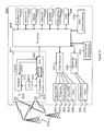
- FIG. 3 is a diagram of a load indication procedure over the X2 interface, according to the prior art.
- FIG. 4 is a table of a relative narrow-band transmission power information element, according to the prior art.
- FIG. 5 is a diagram of an example of E-PDCCH regions, according to an implementation of the disclosure.
- FIG. 6 is a diagram of inter-cell interference for non-interleaved E-PDCCHs, according to an implementation of the disclosure.
- FIG. 7 is a diagram of inter-cell interference for interleaved E-PDCCHs, according to an implementation of the disclosure.
- FIG. 8 is a table of a downlink high interference indication, according to an implementation of the disclosure.
- FIG. 9 is a table of a load information message with a downlink high interference indication added, according to an implementation of the disclosure.
- FIG. 10 is a table of a relative narrow-band transmission power information element with a new field added for an E-PDCCH, according to an implementation of the disclosure.
- FIG. 11 is a table of resource allocation resource block group size vs. downlink system bandwidth, according to the prior art.
- FIG. 12 is an example of resource allocation definition for an E-PDCCH region, according to an implementation of the disclosure.
- FIG. 13 is a table of RNTP-EPDCCH fields that can be added to the RNTP information element, according to an implementation of the disclosure.
- FIG. 14 is a simplified block diagram of an exemplary network element according to one implementation.
- FIG. 15 is a block diagram with an example user equipment capable of being used with the systems and methods in the implementations described herein.
- FIG. 16 illustrates a processor and related components suitable for the several implementations of the present disclosure.
- PDCCHs physical downlink control channels
- the scheduling information may include a resource allocation, a modulation and coding rate (or derived from transport block size), the identity of the intended UE or UEs, and other information.
- a PDCCH could be intended for a single UE, multiple UEs or all UEs in a cell, depending on the nature and content of the scheduled data.
- a broadcast PDCCH is used to carry scheduling information for a physical downlink shared channel (PDSCH) that is intended to be received by all UEs in a cell, such as a PDSCH carrying system information about the eNB.
- PDSCH physical downlink shared channel
- a multicast PDCCH is intended to be received by a group of UEs in a cell.
- a unicast PDCCH is used to carry scheduling information for a PDSCH that is intended to be received by only a single UE.
- FIG. 1 illustrates a typical DL LTE subframe 110 .
- Control information such as the PCFICH (physical control format indicator channel), PHICH (physical HARQ (hybrid automatic repeat request) indicator channel), and PDCCH are transmitted in a control channel region 120 .
- the control channel region 120 includes the first few OFDM (orthogonal frequency division multiplexing) symbols in the subframe 110 .
- the exact number of OFDM symbols for the control channel region 120 is either dynamically indicated by PCFICH, which is transmitted in the first symbol, or semi-statically configured in the case of carrier aggregation in LTE Rel-10.
- the PDSCH, PBCH (physical broadcast channel), PSS/SSS (primary synchronization signal/secondary synchronization signal), and CSI-RS (channel state information reference signal) are transmitted in a PDSCH region 130 .
- DL user data is carried by the PDSCH channels scheduled in the PDSCH region 130 .
- Cell-specific reference signals are transmitted over both the control channel region 120 and the PDSCH region 130 , as described in more detail below.
- Each subframe 110 can include a number of OFDM symbols in the time domain and a number of subcarriers in the frequency domain.
- An OFDM symbol in time and a subcarrier in frequency together define a resource element (RE).
- a physical resource block (RB) can be defined as, for example, in LTE, 12 consecutive subcarriers in the frequency domain and all the OFDM symbols in a slot in the time domain.
- An RB pair with the same RB index in slot 0 ( 140 a ) and slot 1 ( 140 b ) in a subframe can be allocated together.
- Resource blocks can be used to describe the mapping of certain physical channels to resource elements.
- Physical and virtual resource blocks can be defined.
- a virtual resource block (VRB) can be of the same size as a physical resource block (PRB).
- FIG. 2 shows an LTE DL resource grid 210 within each slot 140 in the case of a normal cyclic prefix (CP) configuration.
- the resource grid 210 is defined for each antenna port, i.e., each antenna port has its own separate resource grid 210 .
- Each element in the resource grid 210 for an antenna port is an RE 220 , which is uniquely identified by an index pair of a subcarrier and an OFDM symbol in a slot 140 .
- An RB 230 includes a number of consecutive subcarriers in the frequency domain and a number of consecutive OFDM symbols in the time domain, as shown in the figure.
- An RB 230 is the minimum unit used for the mapping of certain physical channels to REs 220 .
- REGs Resource element groups
- CRSs Cell-specific Reference Signals
- the Load Indication procedure over the X2 interface between two eNBs transfers load and interference coordination information between the eNBs, as shown in FIG. 3 .
- a first eNB 310 a initiates the procedure by sending a Load Information message 320 to a second eNB 310 b to assist in controlling intra-frequency neighboring cells.
- the UL Interference Overload Indication (OI) IE, if present in the Load Information message, indicates the interference level experienced by the indicated cell on all PRBs, per PRB. The receiving eNB may take such information into account when setting its scheduling policy.
- the UL High Interference Indication (HII) IE if present in the Load Information message, indicates, per PRB, the occurrence of high interference sensitivity, as seen from the sending eNB. The receiving eNB should typically try to avoid scheduling cell edge UEs in its cells for the concerned PRBs.
- the Relative Narrowband Tx Power (RNTP) IE can be used for load indication.
- the RNTP IE if present in the Load Information message, indicates, per PRB, whether the downlink transmission power is lower than the value indicated by the RNTP Threshold IE.
- the receiving eNB may take such information into account when setting its scheduling policy. Details of the RNTP IE are shown in the table in FIG. 4 .
- PDCCH capacity enhancement is to transmit downlink control information (DCI) in the legacy PDSCH region. That is, some RBs in the traditional PDSCH region can be reserved for DCI transmission to UEs.
- DCI downlink control information
- E-PDCCH enhanced PDCCH
- a set of RBs and OFDM symbols reserved for this purpose can be referred to as an E-PDCCH region.
- the E-PDCCH region in a subframe is not necessarily completely filled with E-PDCCHs in that any resources in the E-PDCCH region not used for E-PDCCH transmission can be assigned for PDSCH transmission.
- the legacy PDCCH region may or may not be present in a subframe containing an E-PDCCH region.
- the time and frequency resources of an E-PDCCH region may be configurable. An example of an E-PDCCH region is shown in FIG. 5 .
- An E-PDCCH can be assigned to UEs in either a non-interleaved format or an interleaved format.
- a non-interleaved E-PDCCH residing in a set of time-frequency resources, there is no other E-PDCCH for another UE in the same set of time-frequency resources.
- an E-PDCCH can be transmitted on one or several PRBs without cross-interleaving with other E-PDCCHs in a given PRB.
- the interleaved format multiple E-PDCCHs for multiple UEs are interleaved and assigned on the same set of time-frequency resources.
- multiple E-PDCCHs can be cross-interleaved before being transmitted on one or several PRBs.
- the introduction of the E-PDCCH can cause inter-cell interference between eNBs, since the E-PDCCH in a first cell and the PDSCH in a second cell might be transmitted in the same set of time-frequency resources.
- inter-cell interference coordination for the E-PDCCH.
- interference scenarios that may occur include interference from the E-PDCCH in one cell to the PDSCH in adjacent cells, interference from the PDSCH in one cell to the E-PDCCH in adjacent cells, and interference from the E-PDCCH in one cell to the E-PDCCH in adjacent cells.
- the existing RNTP may be used to inform the adjacent cells about the relative transmission power of the E-PDCCH without the E-PDCCH being distinguished from the PDSCH. If the power levels of the E-PDCCH and the PDSCH need to be distinguished, then a new RNTP dedicated to the E-PDCCH may be necessary, as described below.
- adjacent cells may need to avoid allocating an E-PDCCH in the RBs where higher interference may be experienced.
- adjacent cells may need to avoid transmitting PDSCHs with higher power in the same RBs.
- the first and second scenarios described above are illustrated in FIG. 6 with examples of non-interleaved E-PDCCHs.
- the third scenario described above is illustrated in FIG. 7 with an example of an interleaved E-PDCCH interfering with a non-interleaved E-PDCCH.
- Inter-cell interference coordination (ICIC) techniques exist for the PDSCH.
- the situation for the E-PDCCH is different from that of the PDSCH in that the E-PDCCH carries downlink control information, which needs to be received correctly before the related data transmission can be received.
- the E-PDCCH needs to be received with a lower error probability than the PDSCH.
- the DL scheduling information miss detection probability target and the UL scheduling grant miss detection probability target are both 10 ⁇ 2 .
- the normal PDSCH block error probability target is usually around 10 ⁇ 1 .
- the embodiments or implementations disclosed herein provide inter-cell interference coordination for the E-PDCCH.
- the load information carried on the X2 interface can be enhanced to carry E-PDCCH-related information to promote interference-aware scheduling.
- Both the E-PDCCH itself and its victim i.e., a signal in an adjacent cell that is transmitted over the same time-frequency resources as the E-PDCCH) are considered in the enhancement of the load information.
- the E-PDCCH can be protected from strong interference from adjacent cells in two ways. In the E-PDCCH's own cell, the eNB can assign more power to the E-PDCCH than to the PDSCH. In the adjacent cell, the adjacent eNB can lower the power assigned to the relevant RBs. The potentially high interference from an E-PDCCH is also considered for a victim of the E-PDCCH in the adjacent cell. The problem can be exacerbated if relatively higher power is assigned to the E-PDCCH than to the PDSCH.
- an indicator can be exchanged between two eNBs that allows the eNBs to coordinate their transmissions so that an E-PDCCH transmission from one of the eNBs does not cause interference to the other eNB and is not interfered with by the other eNB. That is, a first eNB can ask a second eNB to reduce transmission power or avoid transmitting in one or more resource blocks that the first eNB is using for E-PDCCH transmission so that the second eNB does not interfere with the E-PDCCH transmission.
- the first eNB can inform the second eNB that the first eNB will be transmitting the E-PDCCH at high power on one or more particular resource blocks and that the second eNB should take appropriate measures to avoid interference from the first eNB on those resource blocks.
- the format of individual E-PDCCHs (interleaved or non-interleaved), which is configured by each eNB, may not be exchanged over the X2 interface. Rather, information on the E-PDCCH region is exchanged between eNBs through the X2 interface to better coordinate interference avoidance. This coordination gives scheduling flexibility to individual E-PDCCHs from subframe to subframe. Since the E-PDCCH region definition is expected to be slow-changing, information on the E-PDCCH region can be properly exchanged over X2 without a frequent need to update the information.
- new information regarding the E-PDCCH is transferred between adjacent cells over the X2 interface for better interference coordination.
- this new information can be provided in one of two ways: a new Downlink High Interference Indication (DL HII) IE can be placed directly in the Load Information message sent over the X2 interface or a new E-PDCCH Interference Impact Indication can be placed in the existing RNTP IE within the Load Information message.
- the DL HII will be considered first.
- the DL HII is a new IE that can tell adjacent cells that certain RBs have been configured for an E-PDCCH in a source cell and that any high power transmission in those RBs by an adjacent cell could cause interference to the E-PDCCH.
- the eNB can provide a two-level report on interference sensitivity on the downlink via a binary vector.
- the table in FIG. 8 shows an example of how a DL HII could be constructed.
- the table in FIG. 9 shows an example of the Load Information message with new fields added to indicate the DL HII. The newly implemented fields are underlined in these tables and in the tables referred to hereinafter. While the table in FIG. 9 includes a field of “Target Cell ID” for the DL HII group, that field may be omitted if that field is the same for the UL HII group.
- the sending eNB could mark PRBs of the E-PDCCH region with a value of “1” for high downlink interference sensitivity.
- This indicator received over the X2 interface can be used by the receiving eNB to lower the downlink interference it may cause to those PRBs of the source eNB.
- the receiving eNB can lower the power it uses for those PRBs by scheduling only cell-center UEs on those PRBs.
- the receiving eNB could also avoid scheduling cell-edge UEs in its cell for the concerned PRBs.
- the Target Cell ID IE received within the DL High Interference Information IE group in the Load Information message indicates the cell for which the corresponding DL HII is meant.
- the receiving eNB can consider the value of the DL High Interference Information IE group valid until reception of a new Load Information message carrying an update.
- an E-PDCCH Interference Impact Indication can be added as a new field to the existing RNTP IE within the Load Information message to indicate the E-PDCCH RBs.
- the introduction of such a new field to the RNTP is illustrated in the table in FIG. 10 .
- E-PDCCH resource allocation signaling can be performed in different ways for either the DL HII implementation or the E-PDCH Interference Impact Indication implementation or other mechanisms.
- each bit corresponds to a PRB within the system bandwidth.
- RBG resource block group
- the resource allocation type of the E-PDCCH is signaled together with a corresponding resource mapping.
- a simplified approach can be used if E-PDCCH allocation is limited to certain predefined PRBs.
- bit string that can be used to represent the PRB indication of the E-PDCCH region in FIG. 10 . If the DL HII is dedicated to the E-PDCCH, these definitions can also apply to bit string in FIG. 8 , replacing the value and definition of the bit string of FIG. 8 in accordance with the approach used.
- an RBG-based bitmap may be used to reduce the bitmap size and thus reduce signaling overhead.
- resource allocation Type 0 or Type 1 is used for allocating resources for an E-PDCCH region.
- a RBG is a set of consecutive virtual resource blocks (VRBs) of localized type as defined in section 6.2.3.1 of 3GPP TS 36.211. The RBG sizes for various bandwidths are shown in the table in FIG. 11 .
- the bitmap is of size N RBG bits with one bitmap bit per RBG, such that each RBG is addressable.
- the RBGs can be indexed in order of increasing frequency and non-increasing RBG sizes starting at the lowest frequency.
- the order of the RBG-to-bitmap bit mapping can be such that RBG 0 to RBG (N RBG ⁇ 1) are mapped from the most significant bit (MSB) to the least significant bit (LSB) of the bitmap.
- MSB most significant bit
- LSB least significant bit
- An RBG is allocated for an E-PDCCH region if the corresponding bit value in the bitmap is “1”, and the RBG is not allocated for an E-PDCCH region if the corresponding bit value in the bitmap is “0”, or vice versa.
- RBG subset p where 0 ⁇ p ⁇ P and P is the RBG size, can consist of every Pth RBG starting from RBG p.
- one bit can be used to indicate if a shift of resource allocation within the subset should be used. If the RBG size is P (see FIG.
- the bits used for resource allocation can be as follows: in a first field, ⁇ log 2 (P) ⁇ bits can indicate the selected RBG subset among P RBG subsets, where ⁇ x ⁇ indicates the smallest integer that is greater than or equal to x; in a second field, one bit can be used for shift indication; and a third field can include a bitmap where each bit of the bitmap addresses a single VRB in the selected RBG subset in such a way that MSB to LSB of the bitmap are mapped to the VRBs in increasing frequency order.
- the addressable PRB numbers of a selected RBG subset start from an offset, ⁇ shift (p) to the smallest PRB number within the selected RBG subset, which is mapped to the MSB of the bitmap.
- the offset is in terms of the number of PRBs and is done within the selected RBG subset.
- resource allocation Type 1 gives the flexibility to address individual RBs.
- resource allocation information indicates to a scheduled UE a set of contiguously allocated localized virtual resource blocks or distributed virtual resource blocks. One bit may be needed to indicate if the localized or distributed type of VRB is used.
- a resource allocation field can consist of a resource indication value (RIV) corresponding to a starting resource block (RB start ) and a length in terms of virtually contiguously allocated resource blocks L CRBs .
- a full resource allocation for an E-PDCCH region can be defined as shown in FIG. 12 .
- certain parameters or properties of the E-PDCCH region can be predefined. For example, it can be predefined that only PRBs at the upper and lower bandwidth edges are allocated for E-PDCCHs. In this case, two integer values, RB start and N E-PDCCH , can be signaled over X2 to indicate that N E-PDCCH RBs are located RB start RBs away from both ends of the bandwidth and have been reserved for E-PDCCH transmission. In another example, it can be predefined that the E-PDCCH region comprises L subregions that are D PRBs from each other, where each subregion is composed of N E-PDCCH PRBs. Thus only three parameters need to be signaled: ⁇ L, D, N E-PDCCH ⁇ .
- an E-PDCCH region can be defined to apply only to certain subframes. For instance, interference coordination for the E-PDCCH region might need to be applied only every N subframes, where the period N is an integer ranging from 1 to 10. More broadly speaking, to allow for both periodic and aperiodic allocation, a subframe bitmap can be defined for each eNB to indicate on which subframes coordination for the E-PDCCH region applies. This definition has the benefit of allowing neighbor eNBs to choose different subframe sets to apply the E-PDCCH region so that they can use a similar configuration in the frequency domain, but are separated in the time domain.
- an E-PDCCH region is related to an ABS (almost blank subframe) pattern.
- an E-PDCCH region might only apply to non-ABS subframes.
- no ABS IE is defined over the X2 interface or if ABS is inactive
- coordination for an E-PDCCH region applies to all subframes.
- an ABS IE is defined, then coordination of the E-PDCCH region applies only to those subframes that are not blanked in the ABS pattern.
- a set of non-colliding E-PDCCH region candidates can be predefined, and different eNBs can be allowed to choose a different candidate from the set.
- inter-cell interference coordination techniques described above can apply to the case where the DL HII is used or to the case where the E-PDCCH Interference Impact Indication is used.
- the E-PDCCH transmission power can be signaled through the Load Information message over the X2 interface. More specifically, a power threshold and an indication of whether a PRB exceeds the threshold are signaled to the eNBs in the adjacent cells in the RNTP information element within the Load Information message.
- RNTP-EPDCCH Threshold a second power threshold, which can be referred to as the RNTP-EPDCCH Threshold, can be introduced specifically for an E-PDCCH. Examples of fields that could be related to such a power threshold are illustrated in the table in FIG. 13 .
- RNTP E-PDCCH RNTP E-PDCCH
- RNTP E-PDCCH,threshold is a threshold and may take on one of the following values RNTP E-PDCCH,threshold ⁇ , ⁇ 8, ⁇ , ⁇ 7, ⁇ 6, ⁇ 5, ⁇ 4, ⁇ 3, ⁇ 2, ⁇ 1, 0, +1, +2, +3, +4, +5, +6 ⁇ [dB]; and
- E max ⁇ _ ⁇ nom ( p ) P max ( p ) ⁇ 1 ⁇ ⁇ ⁇ f N RB DL ⁇ N SC RB , where P max (p) is the base station maximum output power described in 3GPP TS 36.104, and N SC RB and ⁇ f are the number of subcarriers in an RB and the subcarrier spacing, respectively, as defined in 3GPP TS 36.211.
- the RNTP E-PDCCH,threshold value range above serves as an example. Other value ranges can be used as well.
- E-PDCCH Interference Impact Indication deals with situations where high order modulation is used for the E-PDCCH.
- QPSK modulation is used for E-PDCCH transmission
- a UE does not need to know amplitude information for the E-PDCCH with respect to a known reference signal in order to demodulate the E-PDCCH.
- high order modulation HOM
- the UE does need amplitude information to properly decode the E-PDCCH.
- the power ratio between the E-PDCCH and the corresponding RS used for E-PDCCH demodulation can be defined and signaled to the UE through higher layer signaling such as radio resource control (RRC) signaling.
- RRC radio resource control
- the ratio of the E-PDCCH EPRE to the RS EPRE among E-PDCCH REs for each OFDM symbol is denoted by either ⁇ A _ E-PDCCH or ⁇ B _ E-PDCCH depending on whether or not the RS is present in the OFDM symbol.
- ⁇ A _ E-PDCCH or ⁇ B _ E-PDCCH can be applied to the same OFDM indices as defined for ⁇ A and ⁇ B given by Table 5.2-2 and Table 5.2-3 of 3GPP TS 36.213.
- ⁇ A _ E-PDCCH and ⁇ B _ E-PDCCH are UE-specific.
- ⁇ A _ E-PDCCH is equal to ⁇ power-offset +P A _ E-PDCCH +10 log 10 (2) [dB] when the UE receives an E-PDCCH transmission using precoding for transmit diversity with four cell-specific antenna ports, according to Section 6.3.4.3 of 3GPP TS 36.211.
- ⁇ A _ E-PDCCH is equal to ⁇ power-offset +P A _ E-PDCCH [dB], where ⁇ power-offset is 0 dB for all E-PDCCH transmission schemes except multi-user MIMO transmission for E-PDCCH, and where P A _ E-PDCCH is a UE-specific parameter provided by higher layers.
- the cell-specific ratio ⁇ B _ E-PDCCH / ⁇ A _ E-PDCCH is given according to a cell-specific parameter P B _ E-PDCCH , similarly to how P B is defined in Table 5.2-1 of 3GPP TS 36.213. This ratio, together with the number of configured eNB cell specific antenna ports, is signaled by higher layers.
- P A _ E-PDCCH and P B _ E-PDCCH could be defined separately as P A and P B and signaled to the UE.
- P A _ E-PDCCH could take larger values than P A to boost the E-PDCCH transmission power.
- P B _ E-PDCCH could take different ratios for from those of P B to improve E-PDCCH transmission.
- the P A _ E-PDCCH and P B _ E-PDCCH could take the same values as P A and P B , respectively. In this case, only P A and P B may need to be signaled to the UE, and hence signaling overhead can be saved.
- the UE may assume that the ratio of the E-PDCCH EPRE to the UE-specific RS EPRE within each OFDM symbol containing a UE-specific RS is 0 dB for a number of transmission layers less than or equal to two. If the number of transmission layers is greater than two, the UE may assume that the ratio of the E-PDCCH EPRE to the UE-specific RS EPRE within each OFDM symbol containing a UE-specific RS is ⁇ 3 dB, which is similar to the PDSCH case.
- a power boosting offset could be included between the E-PDCCH EPRE and the UE-specific RS EPRE.
- power control information for the E-PDCCH can be signaled to a neighboring eNB through the X2 interface.
- P B _ E-PDCCH could be included in RNTP signaling between eNBs if P B _ E-PDCCH is different from P B .
- the P B _ E-PDCCH information indicates power boosting to the cell-specific reference signal (CRS). This information can be used by a neighbor eNB to estimate how much interference can be expected from the serving eNB's CRS. This information may not be necessary if an E-PDCCH RE has the same power level as the PDSCH. This information may be necessary if an E-PDCCH RE does not have the same power level as the PDSCH, for example when more power is given to the E-PDCCH.
- CRS cell-specific reference signal
- Information about an E-PDCCH region can be exchanged between eNBs over X2 to allow better interference coordination for an E-PDCCH than possible if relying on the existing mechanism designed for the PDSCH.
- the time-frequency resources for an E-PDCCH region can be coordinated between eNBs. This coordination provides higher reliability for an E-PDCCH and reduces the influence of an E-PDCCH on neighbor cells. For example, when the DL HII IE is sent from a source eNB, a receiving eNB can lower the downlink interference it may cause to the E-PDCCH PRBs.
- the receiving eNB could lower the power it uses for those PRBs by scheduling cell-center UEs on those PRBs. Alternatively or additionally, the receiving eNB could try to avoid scheduling cell-edge UEs in its cell for the concerned PRBs. In addition, the receiving eNB can avoid allocating E-PDCCHs in those PRBs that are reserved for transmitting the eNB's E-PDCCH region, unless the transmit power can be kept low. Further, information on the transmission power level of the E-PDCCH can be exchanged between eNBs to allow better interference management.
- network element 3110 includes a processor 3120 and a communications subsystem 3130 , where the processor 3120 and communications subsystem 3130 cooperate to perform the methods described above.
- UE 3200 is typically a two-way wireless communication device having voice and data communication capabilities.
- UE 3200 generally has the capability to communicate with other computer systems on the Internet.
- the UE may be referred to as a data messaging device, a two-way pager, a wireless e-mail device, a cellular telephone with data messaging capabilities, a wireless Internet appliance, a wireless device, a mobile device, or a data communication device, as examples.
- UE 3200 may incorporate a communication subsystem 3211 , including a receiver 3212 and a transmitter 3214 , as well as associated components such as one or more antenna elements 3216 and 3218 , local oscillators (LOs) 3213 , and a processing module such as a digital signal processor (DSP) 3220 .
- LOs local oscillators
- DSP digital signal processor
- Network access requirements will also vary depending upon the type of network 3219 .
- network access is associated with a subscriber or user of UE 3200 .
- a UE may require a removable user identity module (RUIM) or a subscriber identity module (SIM) card in order to operate on a network.
- the SIM/RUIM interface 3244 is normally similar to a card-slot into which a SIM/RUIM card can be inserted and ejected.
- the SIM/RUIM card can have memory and hold many key configurations 3251 , and other information 3253 such as identification, and subscriber related information.
- UE 3200 may send and receive communication signals over the network 3219 .
- network 3219 can consist of multiple base stations communicating with the UE.
- Signals received by antenna 3216 through communication network 3219 are input to receiver 3212 , which may perform such common receiver functions as signal amplification, frequency down conversion, filtering, channel selection and the like.
- Analog to digital (A/D) conversion of a received signal allows more complex communication functions such as demodulation and decoding to be performed in the DSP 3220 .
- signals to be transmitted are processed, including modulation and encoding for example, by DSP 3220 and input to transmitter 3214 for digital to analog (D/A) conversion, frequency up conversion, filtering, amplification and transmission over the communication network 3219 via antenna 3218 .
- DSP 3220 not only processes communication signals, but also provides for receiver and transmitter control. For example, the gains applied to communication signals in receiver 3212 and transmitter 3214 may be adaptively controlled through automatic gain control algorithms implemented in DSP 3220 .
- UE 3200 generally includes a processor 3238 which controls the overall operation of the device. Communication functions, including data and voice communications, are performed through communication subsystem 3211 . Processor 3238 also interacts with further device subsystems such as the display 3222 , flash memory 3224 , random access memory (RAM) 3226 , auxiliary input/output (I/O) subsystems 3228 , serial port 3230 , one or more keyboards or keypads 3232 , speaker 3234 , microphone 3236 , other communication subsystem 3240 such as a short-range communications subsystem and any other device subsystems generally designated as 3242 . Serial port 3230 could include a USB port or other port known to those in the art.
- Some of the subsystems shown in FIG. 15 perform communication-related functions, whereas other subsystems may provide “resident” or on-device functions.
- some subsystems such as keyboard 3232 and display 3222 , for example, may be used for both communication-related functions, such as entering a text message for transmission over a communication network, and device-resident functions such as a calculator or task list.
- Operating system software used by the processor 3238 may be stored in a persistent store such as flash memory 3224 , which may instead be a read-only memory (ROM) or similar storage element (not shown).
- ROM read-only memory
- Those skilled in the art will appreciate that the operating system, specific device applications, or parts thereof, may be temporarily loaded into a volatile memory such as RAM 3226 .
- Received communication signals may also be stored in RAM 3226 .
- flash memory 3224 can be segregated into different areas for both computer programs 3258 and program data storage 3250 , 3252 , 3254 and 3256 . These different storage types indicate that each program can allocate a portion of flash memory 3224 for their own data storage requirements.
- Processor 3238 in addition to its operating system functions, may enable execution of software applications on the UE. A predetermined set of applications that control basic operations, including at least data and voice communication applications for example, will normally be installed on UE 3200 during manufacturing. Other applications could be installed subsequently or dynamically.
- the computer readable storage medium may be a tangible or in transitory/non-transitory medium such as optical (e.g., CD, DVD, etc.), magnetic (e.g., tape) or other memory known in the art.
- One software application may be a personal information manager (PIM) application having the ability to organize and manage data items relating to the user of the UE such as, but not limited to, e-mail, calendar events, voice mails, appointments, and task items.
- PIM personal information manager
- Such PIM application may have the ability to send and receive data items, via the wireless network 3219 .
- Further applications may also be loaded onto the UE 3200 through the network 3219 , an auxiliary I/O subsystem 3228 , serial port 3230 , short-range communications subsystem 3240 or any other suitable subsystem 3242 , and installed by a user in the RAM 3226 or a non-volatile store (not shown) for execution by the processor 3238 .
- Such flexibility in application installation increases the functionality of the device and may provide enhanced on-device functions, communication-related functions, or both.
- secure communication applications may enable electronic commerce functions and other such financial transactions to be performed using the UE 3200 .
- a received signal such as a text message or web page download will be processed by the communication subsystem 3211 and input to the processor 3238 , which may further process the received signal for output to the display 3222 , or alternatively to an auxiliary I/O device 3228 .
- a user of UE 3200 may also compose data items such as email messages for example, using the keyboard 3232 , which may be a complete alphanumeric keyboard or telephone-type keypad, among others, in conjunction with the display 3222 and possibly an auxiliary I/O device 3228 . Such composed items may then be transmitted over a communication network through the communication subsystem 3211 .
- UE 3200 For voice communications, overall operation of UE 3200 is similar, except that received signals may typically be output to a speaker 3234 and signals for transmission may be generated by a microphone 3236 .
- Alternative voice or audio I/O subsystems such as a voice message recording subsystem, may also be implemented on UE 3200 .
- voice or audio signal output is preferably accomplished primarily through the speaker 3234
- display 3222 may also be used to provide an indication of the identity of a calling party, the duration of a voice call, or other voice call related information for example.
- Serial port 3230 in FIG. 15 may normally be implemented in a personal digital assistant (PDA)-type UE for which synchronization with a user's desktop computer (not shown) may be desirable, but is an optional device component.
- PDA personal digital assistant
- Such a port 3230 may enable a user to set preferences through an external device or software application and may extend the capabilities of UE 3200 by providing for information or software downloads to UE 3200 other than through a wireless communication network.
- the alternate download path may for example be used to load an encryption key onto the device through a direct and thus reliable and trusted connection to thereby enable secure device communication.
- serial port 3230 can further be used to connect the UE to a computer to act as a modem.
- Other communications subsystems 3240 such as a short-range communications subsystem, is a further optional component which may provide for communication between UE 3200 and different systems or devices, which need not necessarily be similar devices.
- the subsystem 3240 may include an infrared device and associated circuits and components or a BluetoothTM communication module to provide for communication with similarly enabled systems and devices.
- Subsystem 3240 may further include non-cellular communications such as WiFi or WiMAX.
- FIG. 16 illustrates an example of a system 1300 that includes a processing component 1310 suitable for implementing one or more embodiments disclosed herein.
- the system 1300 might include network connectivity devices 1320 , random access memory (RAM) 1330 , read only memory (ROM) 1340 , secondary storage 1350 , and input/output (I/O) devices 1360 .
- RAM random access memory
- ROM read only memory
- secondary storage 1350 secondary storage
- I/O input/output
- These components might communicate with one another via a bus 1370 . In some cases, some of these components may not be present or may be combined in various combinations with one another or with other components not shown.
- DSP digital signal processor
- the processor 1310 executes instructions, codes, computer programs, or scripts that it might access from the network connectivity devices 1320 , RAM 1330 , ROM 1340 , or secondary storage 1350 (which might include various disk-based systems such as hard disk, floppy disk, or optical disk). While only one CPU 1310 is shown, multiple processors may be present. Thus, while instructions may be discussed as being executed by a processor, the instructions may be executed simultaneously, serially, or otherwise by one or multiple processors.
- the processor 1310 may be implemented as one or more CPU chips.
- the network connectivity devices 1320 may take the form of modems, modem banks, Ethernet devices, universal serial bus (USB) interface devices, serial interfaces, token ring devices, fiber distributed data interface (FDDI) devices, wireless local area network (WLAN) devices, radio transceiver devices such as code division multiple access (CDMA) devices, global system for mobile communications (GSM) radio transceiver devices, universal mobile telecommunications system (UMTS) radio transceiver devices, long term evolution (LTE) radio transceiver devices, worldwide interoperability for microwave access (WiMAX) devices, and/or other well-known devices for connecting to networks.
- CDMA code division multiple access
- GSM global system for mobile communications
- UMTS universal mobile telecommunications system
- LTE long term evolution
- WiMAX worldwide interoperability for microwave access
- These network connectivity devices 1320 may enable the processor 1310 to communicate with the Internet or one or more telecommunications networks or other networks from which the processor 1310 might receive information or to which the processor 1310 might output information.
- the network connectivity devices 1320 might also include one or more transceiver components 1325 capable of transmitting and/or receiving data wirelessly.
- the RAM 1330 might be used to store volatile data and perhaps to store instructions that are executed by the processor 1310 .
- the ROM 1340 is a non-volatile memory device that typically has a smaller memory capacity than the memory capacity of the secondary storage 1350 .
- ROM 1340 might be used to store instructions and perhaps data that are read during execution of the instructions. Access to both RAM 1330 and ROM 1340 is typically faster than to secondary storage 1350 .
- the secondary storage 1350 is typically comprised of one or more disk drives or tape drives and might be used for non-volatile storage of data or as an over-flow data storage device if RAM 1330 is not large enough to hold all working data. Secondary storage 1350 may be used to store programs that are loaded into RAM 1330 when such programs are selected for execution.
- the I/O devices 1360 may include liquid crystal displays (LCDs), touch screen displays, keyboards, keypads, switches, dials, mice, track balls, voice recognizers, card readers, paper tape readers, printers, video monitors, or other well-known input/output devices.
- the transceiver 1325 might be considered to be a component of the I/O devices 1360 instead of or in addition to being a component of the network connectivity devices 1320 .
- 3GPP Technical Specification (TS) 36.104 3GPP TS 36.211, 3GPP TS 36.212, 3GPP TS 36.213, 3GPP TS 36.331, and 3GPP TS 36.423.
- a method for communication in a wireless telecommunication system. The method comprises transmitting, by a first access node, an indicator to a second access node over an interface between the first access node and the second access node, wherein the indicator provides information on a transmission of a control channel by the first access node.
- a first access node in a wireless telecommunication system includes a processor configured such that the first access node transmits over an interface between the first access node and a second access node an indicator that provides information on a transmission of a control channel.
- a user equipment in another embodiment, includes a receiving component configured to receive a control channel that was transmitted in a resource block that is frequency-division-multiplexed with a data channel, wherein the resource block is located in a region whose configuration is transmitted from an access node serving the user equipment to another access node. This information exchange between the access nodes is normally performed over the X2 interface.
- the receiving component is further configured to receive power information about the control channel.
- the user equipment also includes a processing component configured such that the user equipment uses the power information to determine a signal amplitude of the control channel.
Abstract
Description
Bit String for E-PDCCH RB indications={b 0 ,b 1 ,b 2 , . . . , b N
where bit b0 corresponds to
where EB(nPRB) is the maximum intended EPRE of E-PDCCH REs in OFDM symbols not containing a reference signal (RS) in this physical resource block on antenna port p in the considered future time interval; nPRB is the physical resource block number nPRB=0, . . . , NRB DL−1; RNTPE-PDCCH,threshold is a threshold and may take on one of the following values RNTPE-PDCCH,thresholdε{−∞, −8, −, −7, −6, −5, −4, −3, −2, −1, 0, +1, +2, +3, +4, +5, +6} [dB]; and
where Pmax (p) is the base station maximum output power described in 3GPP TS 36.104, and NSC RB and Δf are the number of subcarriers in an RB and the subcarrier spacing, respectively, as defined in 3GPP TS 36.211. The RNTPE-PDCCH,threshold value range above serves as an example. Other value ranges can be used as well.
Claims (25)
Priority Applications (6)
| Application Number | Priority Date | Filing Date | Title |
|---|---|---|---|
| US13/289,812 US9473279B2 (en) | 2011-11-04 | 2011-11-04 | Inter-cell interference coordination for E-PDCCH |
| KR1020147015184A KR101629116B1 (en) | 2011-11-04 | 2012-10-30 | Inter-cell interference coordination for e-pdcch |
| PCT/US2012/062591 WO2013066877A1 (en) | 2011-11-04 | 2012-10-30 | Inter-cell interference coordination for e-pdcch |
| CA2854494A CA2854494C (en) | 2011-11-04 | 2012-10-30 | Inter-cell interference coordination for e-pdcch |
| CN201280065828.4A CN104054359B (en) | 2011-11-04 | 2012-10-30 | For E PDCCH Inter-Cell Interference Coordination |
| EP12844712.5A EP2774392B1 (en) | 2011-11-04 | 2012-10-30 | Inter-cell interference coordination for e-pdcch |
Applications Claiming Priority (1)
| Application Number | Priority Date | Filing Date | Title |
|---|---|---|---|
| US13/289,812 US9473279B2 (en) | 2011-11-04 | 2011-11-04 | Inter-cell interference coordination for E-PDCCH |
Publications (2)
| Publication Number | Publication Date |
|---|---|
| US20130114517A1 US20130114517A1 (en) | 2013-05-09 |
| US9473279B2 true US9473279B2 (en) | 2016-10-18 |
Family
ID=48192681
Family Applications (1)
| Application Number | Title | Priority Date | Filing Date |
|---|---|---|---|
| US13/289,812 Active 2034-04-28 US9473279B2 (en) | 2011-11-04 | 2011-11-04 | Inter-cell interference coordination for E-PDCCH |
Country Status (6)
| Country | Link |
|---|---|
| US (1) | US9473279B2 (en) |
| EP (1) | EP2774392B1 (en) |
| KR (1) | KR101629116B1 (en) |
| CN (1) | CN104054359B (en) |
| CA (1) | CA2854494C (en) |
| WO (1) | WO2013066877A1 (en) |
Cited By (3)
| Publication number | Priority date | Publication date | Assignee | Title |
|---|---|---|---|---|
| US20190215807A1 (en) * | 2018-01-11 | 2019-07-11 | Lg Electronics Inc. | Method for receiving downlink signal in wireless communication system and terminal using the same |
| US11039459B2 (en) | 2016-11-03 | 2021-06-15 | Zte Corporation | Data transmission method and apparatus, and electronic device |
| US11219004B2 (en) | 2018-01-11 | 2022-01-04 | Lg Electronics Inc. | Method for receiving downlink signal in wireless communication system and terminal using the same |
Families Citing this family (76)
| Publication number | Priority date | Publication date | Assignee | Title |
|---|---|---|---|---|
| US8711790B2 (en) | 2011-02-11 | 2014-04-29 | Nokia Corporation | DL control channel structure enhancement |
| US8582527B2 (en) | 2011-07-01 | 2013-11-12 | Ofinno Technologies, Llc | Hybrid automatic repeat request in multicarrier systems |
| US8369280B2 (en) | 2011-07-01 | 2013-02-05 | Ofinno Techologies, LLC | Control channels in multicarrier OFDM transmission |
| EP2564611B1 (en) | 2011-07-01 | 2015-02-18 | Ofinno Technologies, LLC | Synchronization signal and control messages in multicarrier OFDM |
| JP5884152B2 (en) | 2011-07-29 | 2016-03-15 | シャープ株式会社 | Base station, terminal, communication system and communication method |
| US8917679B2 (en) | 2011-08-16 | 2014-12-23 | Nokia Corporation | Method for signaling the overlap of downlink control and data channels |
| US8937918B2 (en) | 2011-10-29 | 2015-01-20 | Ofinno Technologies, Llc | Efficient special subframe allocation |
| US11696300B2 (en) | 2011-10-29 | 2023-07-04 | Comcast Cable Communications, Llc | Configuration of reduced transmission power time intervals based on traffic load |
| US8427976B1 (en) | 2011-12-04 | 2013-04-23 | Ofinno Technology, LLC | Carrier information exchange between base stations |
| US8873467B2 (en) * | 2011-12-05 | 2014-10-28 | Ofinno Technologies, Llc | Control channel detection |
| CN103139924B (en) * | 2011-12-05 | 2016-08-31 | 华为技术有限公司 | A kind of method and device of scheduling resource |
| CN102611524B (en) * | 2011-12-19 | 2015-02-04 | 电信科学技术研究院 | Method, system and equipment for information transmission |
| US8971275B2 (en) | 2011-12-31 | 2015-03-03 | Ofinno Technologies, Llc | Almost blank subframe indication in wireless networks |
| CN103188811B (en) * | 2011-12-31 | 2016-08-10 | 华为技术有限公司 | The transmission method of sub-frame information, subscriber equipment and base station |
| CN104025673B (en) * | 2012-01-03 | 2018-06-19 | Lg电子株式会社 | For setting the method and its equipment of down transmitting power in wireless access system |
| EP2805437B1 (en) * | 2012-01-19 | 2020-03-04 | Samsung Electronics Co., Ltd. | Apparatus and method for pilot scrambling for enhanced physical downlink control channels |
| JP5837833B2 (en) * | 2012-01-30 | 2015-12-24 | 株式会社Nttドコモ | Mobile communication method, radio base station, and mobile station |
| US9065600B2 (en) * | 2012-03-14 | 2015-06-23 | Nokia Technologies Oy | Aggregation for a new carrier type |
| JP6399728B2 (en) * | 2012-03-15 | 2018-10-03 | シャープ株式会社 | Base station apparatus, terminal apparatus, communication method, and integrated circuit |
| CN108183773A (en) | 2012-03-16 | 2018-06-19 | 联发科技股份有限公司 | Decoding downlink controls the method and user equipment of information |
| CN103312649B (en) * | 2012-03-16 | 2015-08-19 | 华为终端有限公司 | Transmit the method for Downlink Control Information, base station and subscriber equipment |
| WO2013141585A1 (en) * | 2012-03-19 | 2013-09-26 | 엘지전자 주식회사 | Method and apparatus for transmitting reference signal |
| CN103327521B (en) * | 2012-03-20 | 2016-12-14 | 上海贝尔股份有限公司 | For distributing and detect method and the equipment of downlink control channel resource |
| US9445409B2 (en) * | 2012-03-21 | 2016-09-13 | Mediatek, Inc. | Method for search space configuration of enhanced physical downlink control channel |
| US9497756B2 (en) * | 2012-03-25 | 2016-11-15 | Comcast Cable Communications, Llc | Base station radio resource management |
| US9949265B2 (en) | 2012-05-04 | 2018-04-17 | Comcast Cable Communications, Llc | Control channel in a wireless communication system |
| US9510132B2 (en) * | 2012-05-11 | 2016-11-29 | Qualcomm Incorporation | Methods and apparatus for managing machine-type communications |
| EP2856816A1 (en) * | 2012-06-05 | 2015-04-08 | Nokia Solutions and Networks Oy | Communication method and apparatus |
| US8737276B2 (en) * | 2012-06-27 | 2014-05-27 | Qualcomm Incorporated | Method and apparatus using modified subframes |
| US9668266B2 (en) | 2012-07-04 | 2017-05-30 | Telefonaktiebolaget Lm Ericsson (Publ) | Interference control in HETNETs |
| GB2505489A (en) * | 2012-08-31 | 2014-03-05 | Sony Corp | A mobile communications device for use in a virtual narrowband carrier within a wideband carrier of a mobile communications system |
| EP2900012B1 (en) * | 2012-10-09 | 2016-09-28 | Huawei Technologies Co., Ltd. | Interference coordination method and device |
| US20150319742A1 (en) * | 2012-11-03 | 2015-11-05 | Broadcom Corporation | Resource allocation methods for control channels |
| US11356216B2 (en) * | 2013-01-10 | 2022-06-07 | Texas Instruments Incorporated | Methods and apparatus for dual connectivity operation in a wireless communication network |
| GB2509910B (en) * | 2013-01-16 | 2019-02-20 | Sony Corp | Telecommunications apparatus and methods |
| JP6214878B2 (en) * | 2013-01-31 | 2017-10-18 | 株式会社Nttドコモ | User apparatus, base station, interference reduction method, and interference reduction control information notification method |
| US9838894B2 (en) * | 2013-02-08 | 2017-12-05 | Lg Electronics Inc. | Method for transmitting network support information for removing interference and serving cell base station |
| WO2014131190A1 (en) * | 2013-03-01 | 2014-09-04 | 华为技术有限公司 | Method, apparatus, device, and system for reducing control channel interference |
| CN105210429B (en) * | 2013-05-10 | 2019-08-06 | 上海诺基亚贝尔股份有限公司 | Signaling methods and device for Inter-Cell Interference Coordination |
| CN104244415B (en) * | 2013-06-19 | 2018-08-07 | 上海诺基亚贝尔股份有限公司 | A method of configuration enhancing Physical Downlink Control Channel |
| JP6174141B2 (en) * | 2013-06-26 | 2017-08-02 | 京セラ株式会社 | Communication control method and base station |
| US9301314B2 (en) * | 2013-10-08 | 2016-03-29 | Broadcom Corporation | WLAN and LTE time division based scheduling devices and methods |
| KR102199693B1 (en) * | 2013-11-01 | 2021-01-07 | 후아웨이 테크놀러지 컴퍼니 리미티드 | Apparatus and Method for Cancelling Inter-cell Interference in Wireless Communication System |
| CN104703212B (en) * | 2013-12-06 | 2019-07-23 | 索尼公司 | Device, wireless communication system and method in wireless communication system |
| US9629143B2 (en) * | 2014-01-06 | 2017-04-18 | Intel IP Corporation | Systems, methods, and devices for enhancing spectral efficiency with network-assisted advanced receivers |
| CN104902496B (en) * | 2014-03-07 | 2020-02-14 | 中兴通讯股份有限公司 | Method and device for coordinating interference between cells |
| WO2015136325A1 (en) * | 2014-03-11 | 2015-09-17 | Telefonaktiebolaget L M Ericsson (Publ) | Physical downlink control channel (pdcch) inter-cell-interference coordination |
| US9888469B2 (en) | 2014-03-19 | 2018-02-06 | Nec Corporation | Signalling for coordinated multi-point transmission and reception (CoMP) |
| CN104935396B (en) * | 2014-03-20 | 2019-09-10 | 中兴通讯股份有限公司 | The signaling methods and system, method of reseptance and device that interference is eliminated or inhibited |
| US9516564B2 (en) | 2014-04-25 | 2016-12-06 | At&T Intellectual Property I, L.P. | Enhancement of a cell reselection parameter in heterogeneous networks |
| US9635566B2 (en) | 2014-04-25 | 2017-04-25 | At&T Intellectual Property I, L.P. | Enhancement of access points to support heterogeneous networks |
| US11432305B2 (en) * | 2014-05-19 | 2022-08-30 | Qualcomm Incorporated | Apparatus and method for synchronous multiplexing and multiple access for different latency targets utilizing thin control |
| US11019620B2 (en) | 2014-05-19 | 2021-05-25 | Qualcomm Incorporated | Apparatus and method for inter-band pairing of carriers for time division duplex transmit- and receive-switching and its application to multiplexing of different transmission time intervals |
| US10230507B2 (en) * | 2014-09-25 | 2019-03-12 | Nec Corporation | Signalling in coordinated multi-point transmission and reception (CoMP) |
| US10224986B2 (en) | 2014-09-25 | 2019-03-05 | Nec Corporation | Signalling in coordinated multi-point transmission and reception (CoMP) |
| US9621294B2 (en) | 2014-10-02 | 2017-04-11 | At&T Intellectual Property I, L.P. | Enhancement of inter-cell interference coordination with adaptive reduced-power almost blank subframes based on neighbor cell profile data |
| US9629144B1 (en) | 2014-11-03 | 2017-04-18 | Sprint Spectrum L.P. | Management of time segment use for wireless communication |
| CN107113787B (en) * | 2014-11-07 | 2021-03-02 | 松下电器(美国)知识产权公司 | Improved resource assignment for transmission on unlicensed carriers |
| US9674809B1 (en) | 2014-11-17 | 2017-06-06 | Sprint Spectrum L.P. | Management of component carriers based on time segment coordination |
| US9794943B1 (en) | 2014-12-18 | 2017-10-17 | Sprint Spectrum L.P. | Dynamic scheduling based on carrier aggregation capabilities |
| US10085266B1 (en) | 2015-02-26 | 2018-09-25 | Sprint Spectrum L.P. | Management of TTI bundling for carrier aggregated communications |
| US20160277942A1 (en) * | 2015-03-17 | 2016-09-22 | Qualcomm Incorporated | Load-aware channel state reference signal transmission |
| US10149125B1 (en) | 2015-04-10 | 2018-12-04 | Sprint Spectrum L.P. | Dynamic adjustment of uplink coordinated multipoint service |
| US10432368B1 (en) | 2015-04-17 | 2019-10-01 | Sprint Spectrum L.P. | Balancing of transmission time interval bundling and coordinate multipoint |
| US9554375B1 (en) | 2015-05-01 | 2017-01-24 | Sprint Spectrum L.P. | Sector selection for coordinated multipoint based on application type |
| US9629136B1 (en) | 2015-05-22 | 2017-04-18 | Sprint Spectrum L.P. | Method and system for reducing PRACH interference |
| WO2017017881A1 (en) * | 2015-07-24 | 2017-02-02 | パナソニック インテレクチュアル プロパティ コーポレーション オブ アメリカ | Base station, terminal, transmission method, and reception method |
| US9848437B1 (en) * | 2015-08-21 | 2017-12-19 | Sprint Spectrum L.P. | Management of uplink control signaling in wireless adjacent coverage areas |
| TWI763633B (en) * | 2015-08-25 | 2022-05-11 | 美商Idac控股公司 | Wireless transmit/receive unit and method implemented therein |
| US10064199B2 (en) | 2015-10-06 | 2018-08-28 | Qualcomm Incorporated | Techniques for system information block (SIB) management using SIB resource block allocation and physical downlink shared channel (PDSCH) data resource block blanking |
| US10211907B1 (en) | 2016-05-26 | 2019-02-19 | Sprint Spectrum L.P. | Coordinated multipoint mode selection for relay base station |
| CN107070581B (en) * | 2016-12-29 | 2019-10-25 | 上海华为技术有限公司 | A kind of interference elimination method and base station |
| WO2018145303A1 (en) * | 2017-02-10 | 2018-08-16 | 华为技术有限公司 | Communication method and device |
| US10237759B1 (en) | 2017-03-29 | 2019-03-19 | Sprint Spectrum L.P. | Coordinated multipoint set selection based on donor status |
| KR20190027705A (en) * | 2017-09-07 | 2019-03-15 | 엘지전자 주식회사 | Apparatus and method for allocating resources in a wireless communication system |
| KR20200121108A (en) * | 2019-04-15 | 2020-10-23 | 에스케이하이닉스 주식회사 | Memory system for interference compensation and operating method of memory system |
Citations (9)
| Publication number | Priority date | Publication date | Assignee | Title |
|---|---|---|---|---|
| US20080186862A1 (en) | 2007-02-05 | 2008-08-07 | Telefonaktiebolaget Lm Ericsson (Publ) | Congestion/load indication for high speed packet access |
| US20080247375A1 (en) | 2007-04-03 | 2008-10-09 | Tarik Muharemovic | Network-Based Inter-Cell Power Control For Multi-Channel Wireless Networks |
| US20100220626A1 (en) | 2005-12-22 | 2010-09-02 | Qualcomm Incorporated | Methods and apparatus for communicating transmission backlog information |
| US20110002285A1 (en) * | 2009-07-02 | 2011-01-06 | Samsung Electronics Co. Ltd. | Apparatus and method for managing resource to decrease inter-cell interference in a broadband wireless commmunication system |
| US20110170496A1 (en) | 2010-01-11 | 2011-07-14 | Research In Motion Limited | Control Channel Interference Management and Extended PDCCH for Heterogeneous Network |
| WO2011119750A1 (en) | 2010-03-23 | 2011-09-29 | Interdigital Patent Holdings, Inc. | Method, apparatus and system for enabling resource coordination in cellular networks |
| CA2792762A1 (en) | 2010-04-14 | 2011-10-20 | Lg Electronics Inc. | Method for setting a search space for a relay node in a wireless communication system and apparatus for same |
| US20120014333A1 (en) * | 2010-07-13 | 2012-01-19 | Samsung Electronics Co., Ltd. | Inter-cell interference coordination method and apparatus for an ofdm-based heterogeneous cellular system |
| WO2013036005A1 (en) * | 2011-09-05 | 2013-03-14 | Lg Electronics Inc. | Method of indicating a control channel in a wireless access system, base station for the same and user equipment for the same |
Family Cites Families (1)
| Publication number | Priority date | Publication date | Assignee | Title |
|---|---|---|---|---|
| CN101917367B (en) * | 2010-09-06 | 2013-02-27 | 北京交通大学 | Method for intercell interference coordination of downlink control channel in LTE-Advanced heterogeneous network |
-
2011
- 2011-11-04 US US13/289,812 patent/US9473279B2/en active Active
-
2012
- 2012-10-30 KR KR1020147015184A patent/KR101629116B1/en active IP Right Grant
- 2012-10-30 WO PCT/US2012/062591 patent/WO2013066877A1/en active Application Filing
- 2012-10-30 CN CN201280065828.4A patent/CN104054359B/en active Active
- 2012-10-30 CA CA2854494A patent/CA2854494C/en active Active
- 2012-10-30 EP EP12844712.5A patent/EP2774392B1/en active Active
Patent Citations (9)
| Publication number | Priority date | Publication date | Assignee | Title |
|---|---|---|---|---|
| US20100220626A1 (en) | 2005-12-22 | 2010-09-02 | Qualcomm Incorporated | Methods and apparatus for communicating transmission backlog information |
| US20080186862A1 (en) | 2007-02-05 | 2008-08-07 | Telefonaktiebolaget Lm Ericsson (Publ) | Congestion/load indication for high speed packet access |
| US20080247375A1 (en) | 2007-04-03 | 2008-10-09 | Tarik Muharemovic | Network-Based Inter-Cell Power Control For Multi-Channel Wireless Networks |
| US20110002285A1 (en) * | 2009-07-02 | 2011-01-06 | Samsung Electronics Co. Ltd. | Apparatus and method for managing resource to decrease inter-cell interference in a broadband wireless commmunication system |
| US20110170496A1 (en) | 2010-01-11 | 2011-07-14 | Research In Motion Limited | Control Channel Interference Management and Extended PDCCH for Heterogeneous Network |
| WO2011119750A1 (en) | 2010-03-23 | 2011-09-29 | Interdigital Patent Holdings, Inc. | Method, apparatus and system for enabling resource coordination in cellular networks |
| CA2792762A1 (en) | 2010-04-14 | 2011-10-20 | Lg Electronics Inc. | Method for setting a search space for a relay node in a wireless communication system and apparatus for same |
| US20120014333A1 (en) * | 2010-07-13 | 2012-01-19 | Samsung Electronics Co., Ltd. | Inter-cell interference coordination method and apparatus for an ofdm-based heterogeneous cellular system |
| WO2013036005A1 (en) * | 2011-09-05 | 2013-03-14 | Lg Electronics Inc. | Method of indicating a control channel in a wireless access system, base station for the same and user equipment for the same |
Non-Patent Citations (15)
| Title |
|---|
| 3GPP TS 36.211 V10.1.0; 3rd Generation Partnership Project; Technical Specification Group Radio Access Network; Evolved Universal Terrestrial Radio Access (E-UTRA); Physical Channels and Modulation; Release 10; Mar. 2011; 103 pages. |
| 3GPP TS 36.212 V10.1.0; 3rd Generation Partnership Project; Technical Specification Group Radio Access Network; Evolved Universal Terrestrial Radio Access (E-UTRA); Mutiplexing and Channel Coding; Release 10; Mar. 2011; 76 pages. |
| 3GPP TS 36.213 V10.1.0; 3rd Generation Partnership Project; Technical Specification Group Radio Access Network; Evolved Universal Terrestrial Radio Access (E-UTRA); Physical Layer Procedures; Release 10; Mar. 2011; 115 pages. |
| 3GPP TS 36.213 V10.3.0; 3rd Generation Partnership Project; Technical Specification Group Radio Access Network; Evolved Universal Terrestrial Radio Access (E-UTRA); Physical Layer Procedures; Release 10; Sep. 2011; 122 pages. |
| 3GPP TS 36.331 V10.1.0; 3rd Generation Partnership Project; Technical Specification Group Radio Access Network; Evolved Universal Terrestrial Radio Access (E-UTRA); Radio Resource Control (RRC); Protocol Specification; Release 10; Mar. 2011; 290 pages. |
| 3GPP TS 36.423 V10.2.0; 3rd Generation Partnership Project; Technical Specification Group Radio Access Network; Evolved Universal Terrestrial Radio Access Network (E-UTRAN); X2 Application Protocol (X2AP); Release 10; Jun. 2011; 130 pages. |
| 3GPP TS 36.423 V10.3.0; 3rd Generation Partnership Project; Technical Specification Group Radio Access Network; Evolved Universal Terrestrial Radio Access Network (E-UTRAN); X2 Application Protocol (X2AP); Release 10; Sep. 2011; 132 pages. |
| 3GPP TSG RAN WG1 Meeting #66bis; "Considerations on Enhanced PDCCH"; R1-113130; Zhuhai, China; Oct. 10-14, 2011; 3 pages. |
| 3GPP TSG-RAN WG1 Meeting #66bis; "Discussion on Enhanced Downlink Control Channel Design"; R1-113223; Zhuhai, China; Oct. 10-14, 2011; 3 pages. |
| European Examination Report; Application No. 12844712.5; May 9, 2016; 5 pages. |
| European Extended Search Report; Application No. 12844712.5; May 26, 2015; 10 pages. |
| Korean Office Action as Received in Co-pending Application No. 10-2014-7015184 on Aug. 11, 2015; 4 pages. (No English translation available). |
| Korean Office Action as Received in Co-pending Application No. 10-2014-7015184 on Feb. 5, 2016; 4 pages. (No English translation available). |
| PCT International Search Report; Application No. PCT/US2012/062591; Jan. 22, 2013; 2 pages. |
| PCT Written Opinion of the International Searching Authority; Application No. PCT/US2012/062591; Jan. 22, 2013; 5 pages. |
Cited By (5)
| Publication number | Priority date | Publication date | Assignee | Title |
|---|---|---|---|---|
| US11039459B2 (en) | 2016-11-03 | 2021-06-15 | Zte Corporation | Data transmission method and apparatus, and electronic device |
| US20190215807A1 (en) * | 2018-01-11 | 2019-07-11 | Lg Electronics Inc. | Method for receiving downlink signal in wireless communication system and terminal using the same |
| US10448388B2 (en) * | 2018-01-11 | 2019-10-15 | Lg Electronics Inc. | Method for receiving downlink signal in wireless communication system and terminal using the same |
| US11219004B2 (en) | 2018-01-11 | 2022-01-04 | Lg Electronics Inc. | Method for receiving downlink signal in wireless communication system and terminal using the same |
| US11716743B2 (en) | 2018-01-11 | 2023-08-01 | Lg Electronics Inc. | Method for receiving downlink signal in wireless communication system and terminal using the same |
Also Published As
| Publication number | Publication date |
|---|---|
| CA2854494A1 (en) | 2013-05-10 |
| KR20140099265A (en) | 2014-08-11 |
| EP2774392A4 (en) | 2015-06-24 |
| WO2013066877A1 (en) | 2013-05-10 |
| CN104054359A (en) | 2014-09-17 |
| CN104054359B (en) | 2018-02-06 |
| EP2774392B1 (en) | 2019-06-19 |
| KR101629116B1 (en) | 2016-06-09 |
| CA2854494C (en) | 2021-02-23 |
| US20130114517A1 (en) | 2013-05-09 |
| EP2774392A1 (en) | 2014-09-10 |
Similar Documents
| Publication | Publication Date | Title |
|---|---|---|
| US9473279B2 (en) | Inter-cell interference coordination for E-PDCCH | |
| US10063351B2 (en) | Enhanced common downlink control channels | |
| US9998268B2 (en) | Enhanced PHICH transmission for LTE-advanced | |
| US20170156132A1 (en) | Design on Enhanced Control Channel For Wireless System | |
| EP2805438B1 (en) | E-pdcch design for reducing blind decoding | |
| US20130343477A9 (en) | PUSCH Reference Signal Design for High Doppler Frequency | |
| WO2013003218A2 (en) | Method and apparatus for enhancing downlink control information transmission | |
| US9467990B2 (en) | Method and apparatus for detecting control channel in wireless communication system | |
| US20230345506A1 (en) | Downlink Control Information (DCI) Transmission and Reception |
Legal Events
| Date | Code | Title | Description |
|---|---|---|---|
| AS | Assignment |
Owner name: RESEARCH IN MOTION LIMITED, CANADA Free format text: ASSIGNMENT OF ASSIGNORS INTEREST;ASSIGNORS:GAO, SHIWEI;XU, HUA;REEL/FRAME:027247/0464 Effective date: 20111103 Owner name: RESEARCH IN MOTION CORPORATION, DELAWARE Free format text: ASSIGNMENT OF ASSIGNORS INTEREST;ASSIGNOR:BLANKENSHIP, YUFEI WU;REEL/FRAME:027247/0412 Effective date: 20111103 |
|
| AS | Assignment |
Owner name: RESEARCH IN MOTION LIMITED, ONTARIO Free format text: ASSIGNMENT OF ASSIGNORS INTEREST;ASSIGNOR:RESEARCH IN MOTION CORPORATION;REEL/FRAME:027352/0576 Effective date: 20111205 |
|
| AS | Assignment |
Owner name: BLACKBERRY LIMITED, ONTARIO Free format text: CHANGE OF NAME;ASSIGNOR:RESEARCH IN MOTION LIMITED;REEL/FRAME:038087/0963 Effective date: 20130709 |
|
| STCF | Information on status: patent grant |
Free format text: PATENTED CASE |
|
| MAFP | Maintenance fee payment |
Free format text: PAYMENT OF MAINTENANCE FEE, 4TH YEAR, LARGE ENTITY (ORIGINAL EVENT CODE: M1551); ENTITY STATUS OF PATENT OWNER: LARGE ENTITY Year of fee payment: 4 |
|
| AS | Assignment |
Owner name: OT PATENT ESCROW, LLC, ILLINOIS Free format text: ASSIGNMENT OF ASSIGNORS INTEREST;ASSIGNOR:BLACKBERRY LIMITED;REEL/FRAME:063471/0474 Effective date: 20230320 |
|
| AS | Assignment |
Owner name: MALIKIE INNOVATIONS LIMITED, IRELAND Free format text: NUNC PRO TUNC ASSIGNMENT;ASSIGNOR:OT PATENT ESCROW, LLC;REEL/FRAME:064015/0001 Effective date: 20230511 |
|
| AS | Assignment |
Owner name: MALIKIE INNOVATIONS LIMITED, IRELAND Free format text: NUNC PRO TUNC ASSIGNMENT;ASSIGNOR:BLACKBERRY LIMITED;REEL/FRAME:064066/0001 Effective date: 20230511 |
|
| AS | Assignment |
Owner name: MALIKIE INNOVATIONS LIMITED, IRELAND Free format text: CORRECTIVE ASSIGNMENT TO CORRECT 12817157 APPLICATION NUMBER PREVIOUSLY RECORDED AT REEL: 064015 FRAME: 0001. ASSIGNOR(S) HEREBY CONFIRMS THE ASSIGNMENT;ASSIGNOR:OT PATENT ESCROW, LLC;REEL/FRAME:064807/0001 Effective date: 20230511 Owner name: MALIKIE INNOVATIONS LIMITED, IRELAND Free format text: CORRECTIVE ASSIGNMENT TO CORRECT THE REMOVE APPLICATION NUMBER PREVIOUSLY RECORDED AT REEL: 064015 FRAME: 0001. ASSIGNOR(S) HEREBY CONFIRMS THE ASSIGNMENT;ASSIGNOR:OT PATENT ESCROW, LLC;REEL/FRAME:064807/0001 Effective date: 20230511 Owner name: OT PATENT ESCROW, LLC, ILLINOIS Free format text: CORRECTIVE ASSIGNMENT TO CORRECT THE COVER SHEET AT PAGE 50 TO REMOVE 12817157 PREVIOUSLY RECORDED ON REEL 063471 FRAME 0474. ASSIGNOR(S) HEREBY CONFIRMS THE ASSIGNMENT;ASSIGNOR:BLACKBERRY LIMITED;REEL/FRAME:064806/0669 Effective date: 20230320 |