US9717461B2 - Systems, devices, and methods for tracking and compensating for patient motion during a medical imaging scan - Google Patents
Systems, devices, and methods for tracking and compensating for patient motion during a medical imaging scan Download PDFInfo
- Publication number
- US9717461B2 US9717461B2 US14/762,581 US201414762581A US9717461B2 US 9717461 B2 US9717461 B2 US 9717461B2 US 201414762581 A US201414762581 A US 201414762581A US 9717461 B2 US9717461 B2 US 9717461B2
- Authority
- US
- United States
- Prior art keywords
- sight
- line
- motion
- tracking
- optically visible
- Prior art date
- Legal status (The legal status is an assumption and is not a legal conclusion. Google has not performed a legal analysis and makes no representation as to the accuracy of the status listed.)
- Active, expires
Links
Images


Classifications
-
- A—HUMAN NECESSITIES
- A61—MEDICAL OR VETERINARY SCIENCE; HYGIENE
- A61B—DIAGNOSIS; SURGERY; IDENTIFICATION
- A61B5/00—Measuring for diagnostic purposes; Identification of persons
- A61B5/72—Signal processing specially adapted for physiological signals or for diagnostic purposes
- A61B5/7203—Signal processing specially adapted for physiological signals or for diagnostic purposes for noise prevention, reduction or removal
- A61B5/7207—Signal processing specially adapted for physiological signals or for diagnostic purposes for noise prevention, reduction or removal of noise induced by motion artifacts
- A61B5/721—Signal processing specially adapted for physiological signals or for diagnostic purposes for noise prevention, reduction or removal of noise induced by motion artifacts using a separate sensor to detect motion or using motion information derived from signals other than the physiological signal to be measured
-
- A—HUMAN NECESSITIES
- A61—MEDICAL OR VETERINARY SCIENCE; HYGIENE
- A61B—DIAGNOSIS; SURGERY; IDENTIFICATION
- A61B5/00—Measuring for diagnostic purposes; Identification of persons
- A61B5/05—Detecting, measuring or recording for diagnosis by means of electric currents or magnetic fields; Measuring using microwaves or radio waves
- A61B5/055—Detecting, measuring or recording for diagnosis by means of electric currents or magnetic fields; Measuring using microwaves or radio waves involving electronic [EMR] or nuclear [NMR] magnetic resonance, e.g. magnetic resonance imaging
-
- A—HUMAN NECESSITIES
- A61—MEDICAL OR VETERINARY SCIENCE; HYGIENE
- A61B—DIAGNOSIS; SURGERY; IDENTIFICATION
- A61B5/00—Measuring for diagnostic purposes; Identification of persons
- A61B5/103—Detecting, measuring or recording devices for testing the shape, pattern, colour, size or movement of the body or parts thereof, for diagnostic purposes
- A61B5/11—Measuring movement of the entire body or parts thereof, e.g. head or hand tremor, mobility of a limb
- A61B5/1121—Determining geometric values, e.g. centre of rotation or angular range of movement
-
- A—HUMAN NECESSITIES
- A61—MEDICAL OR VETERINARY SCIENCE; HYGIENE
- A61B—DIAGNOSIS; SURGERY; IDENTIFICATION
- A61B5/00—Measuring for diagnostic purposes; Identification of persons
- A61B5/103—Detecting, measuring or recording devices for testing the shape, pattern, colour, size or movement of the body or parts thereof, for diagnostic purposes
- A61B5/11—Measuring movement of the entire body or parts thereof, e.g. head or hand tremor, mobility of a limb
- A61B5/1126—Measuring movement of the entire body or parts thereof, e.g. head or hand tremor, mobility of a limb using a particular sensing technique
- A61B5/1127—Measuring movement of the entire body or parts thereof, e.g. head or hand tremor, mobility of a limb using a particular sensing technique using markers
-
- A—HUMAN NECESSITIES
- A61—MEDICAL OR VETERINARY SCIENCE; HYGIENE
- A61B—DIAGNOSIS; SURGERY; IDENTIFICATION
- A61B5/00—Measuring for diagnostic purposes; Identification of persons
- A61B5/68—Arrangements of detecting, measuring or recording means, e.g. sensors, in relation to patient
- A61B5/6801—Arrangements of detecting, measuring or recording means, e.g. sensors, in relation to patient specially adapted to be attached to or worn on the body surface
- A61B5/6813—Specially adapted to be attached to a specific body part
- A61B5/6814—Head
- A61B5/682—Mouth, e.g., oral cavity; tongue; Lips; Teeth
-
- A—HUMAN NECESSITIES
- A61—MEDICAL OR VETERINARY SCIENCE; HYGIENE
- A61B—DIAGNOSIS; SURGERY; IDENTIFICATION
- A61B5/00—Measuring for diagnostic purposes; Identification of persons
- A61B5/70—Means for positioning the patient in relation to the detecting, measuring or recording means
- A61B5/702—Posture restraints
-
- A—HUMAN NECESSITIES
- A61—MEDICAL OR VETERINARY SCIENCE; HYGIENE
- A61B—DIAGNOSIS; SURGERY; IDENTIFICATION
- A61B5/00—Measuring for diagnostic purposes; Identification of persons
- A61B5/72—Signal processing specially adapted for physiological signals or for diagnostic purposes
- A61B5/7235—Details of waveform analysis
- A61B5/725—Details of waveform analysis using specific filters therefor, e.g. Kalman or adaptive filters
-
- A—HUMAN NECESSITIES
- A61—MEDICAL OR VETERINARY SCIENCE; HYGIENE
- A61B—DIAGNOSIS; SURGERY; IDENTIFICATION
- A61B5/00—Measuring for diagnostic purposes; Identification of persons
- A61B5/74—Details of notification to user or communication with user or patient ; user input means
- A61B5/7475—User input or interface means, e.g. keyboard, pointing device, joystick
- A61B5/748—Selection of a region of interest, e.g. using a graphics tablet
- A61B5/7485—Automatic selection of region of interest
-
- G—PHYSICS
- G01—MEASURING; TESTING
- G01R—MEASURING ELECTRIC VARIABLES; MEASURING MAGNETIC VARIABLES
- G01R33/00—Arrangements or instruments for measuring magnetic variables
- G01R33/20—Arrangements or instruments for measuring magnetic variables involving magnetic resonance
- G01R33/28—Details of apparatus provided for in groups G01R33/44 - G01R33/64
- G01R33/283—Intercom or optical viewing arrangements, structurally associated with NMR apparatus
-
- G—PHYSICS
- G06—COMPUTING; CALCULATING OR COUNTING
- G06T—IMAGE DATA PROCESSING OR GENERATION, IN GENERAL
- G06T7/00—Image analysis
- G06T7/20—Analysis of motion
- G06T7/246—Analysis of motion using feature-based methods, e.g. the tracking of corners or segments
- G06T7/248—Analysis of motion using feature-based methods, e.g. the tracking of corners or segments involving reference images or patches
-
- G—PHYSICS
- G06—COMPUTING; CALCULATING OR COUNTING
- G06T—IMAGE DATA PROCESSING OR GENERATION, IN GENERAL
- G06T7/00—Image analysis
- G06T7/70—Determining position or orientation of objects or cameras
- G06T7/73—Determining position or orientation of objects or cameras using feature-based methods
- G06T7/74—Determining position or orientation of objects or cameras using feature-based methods involving reference images or patches
-
- A—HUMAN NECESSITIES
- A61—MEDICAL OR VETERINARY SCIENCE; HYGIENE
- A61B—DIAGNOSIS; SURGERY; IDENTIFICATION
- A61B90/00—Instruments, implements or accessories specially adapted for surgery or diagnosis and not covered by any of the groups A61B1/00 - A61B50/00, e.g. for luxation treatment or for protecting wound edges
- A61B90/39—Markers, e.g. radio-opaque or breast lesions markers
- A61B2090/3937—Visible markers
-
- A—HUMAN NECESSITIES
- A61—MEDICAL OR VETERINARY SCIENCE; HYGIENE
- A61N—ELECTROTHERAPY; MAGNETOTHERAPY; RADIATION THERAPY; ULTRASOUND THERAPY
- A61N5/00—Radiation therapy
- A61N5/10—X-ray therapy; Gamma-ray therapy; Particle-irradiation therapy
- A61N5/1048—Monitoring, verifying, controlling systems and methods
- A61N5/1049—Monitoring, verifying, controlling systems and methods for verifying the position of the patient with respect to the radiation beam
- A61N2005/1059—Monitoring, verifying, controlling systems and methods for verifying the position of the patient with respect to the radiation beam using cameras imaging the patient
-
- G—PHYSICS
- G01—MEASURING; TESTING
- G01R—MEASURING ELECTRIC VARIABLES; MEASURING MAGNETIC VARIABLES
- G01R33/00—Arrangements or instruments for measuring magnetic variables
- G01R33/20—Arrangements or instruments for measuring magnetic variables involving magnetic resonance
- G01R33/44—Arrangements or instruments for measuring magnetic variables involving magnetic resonance using nuclear magnetic resonance [NMR]
- G01R33/48—NMR imaging systems
- G01R33/54—Signal processing systems, e.g. using pulse sequences ; Generation or control of pulse sequences; Operator console
- G01R33/56—Image enhancement or correction, e.g. subtraction or averaging techniques, e.g. improvement of signal-to-noise ratio and resolution
- G01R33/565—Correction of image distortions, e.g. due to magnetic field inhomogeneities
- G01R33/56509—Correction of image distortions, e.g. due to magnetic field inhomogeneities due to motion, displacement or flow, e.g. gradient moment nulling
-
- G—PHYSICS
- G06—COMPUTING; CALCULATING OR COUNTING
- G06T—IMAGE DATA PROCESSING OR GENERATION, IN GENERAL
- G06T2207/00—Indexing scheme for image analysis or image enhancement
- G06T2207/10—Image acquisition modality
- G06T2207/10016—Video; Image sequence
-
- G—PHYSICS
- G06—COMPUTING; CALCULATING OR COUNTING
- G06T—IMAGE DATA PROCESSING OR GENERATION, IN GENERAL
- G06T2207/00—Indexing scheme for image analysis or image enhancement
- G06T2207/10—Image acquisition modality
- G06T2207/10016—Video; Image sequence
- G06T2207/10021—Stereoscopic video; Stereoscopic image sequence
-
- G—PHYSICS
- G06—COMPUTING; CALCULATING OR COUNTING
- G06T—IMAGE DATA PROCESSING OR GENERATION, IN GENERAL
- G06T2207/00—Indexing scheme for image analysis or image enhancement
- G06T2207/30—Subject of image; Context of image processing
- G06T2207/30204—Marker
Definitions
- the disclosure relates generally to the field of motion tracking, and more specifically to systems, devices, and methods for tracking and compensating for patient motion during a medical imaging scan.
- MRI magnetic resonance imaging
- An MRI scanner is a device in which the patient or a portion of the patient's body is positioned within a powerful magnet where a magnetic field is used to align the magnetization of some atomic nuclei (usually hydrogen nuclei-protons) and radio frequency magnetic fields are applied to systematically alter the alignment of this magnetization. This causes the nuclei to produce a rotating magnetic field detectable by the scanner and this information is recorded to construct an image of the scanned region of the body.
- These scans typically take several minutes (up to about 40 minutes in some scanners) and in prior art devices any significant movement can ruin the images and require the scan to be repeated.
- radiation therapy can be applied to a targeted tissue region.
- radiation therapy can be dynamically applied in response to patient movements.
- the tracking of patient movements does not have a high degree of accuracy. Accordingly, the use of such systems can result in the application of radiation therapy to non-targeted tissue regions, thereby unintentionally harming healthy tissue while intentionally affecting diseased tissue.
- proton therapies and other therapies are also true for proton therapies and other therapies.
- the disclosure herein provides systems, devices, and methods for tracking and compensating for patient motion during a medical imaging scan, such as during a magnetic resonance imaging scan.
- a first sensor e.g., a first camera
- a second sensor e.g., a second camera
- a marker or target such as a compact, inexpensive target which mounts comfortably and rigidly to the subject's skeletal frame.
- the camera can be configured to detect any desired wavelength or range of wavelengths of energy, including one or more of the infrared, near-infrared, visible, or ultraviolet spectra for example.
- Some preferred embodiments can track head and other body motion having up to and including six degrees of freedom (sometimes referred to as 6-DOF).
- a motion compensation system for tracking and compensating for patient motion during a medical imaging scan comprises: an optical marker comprising an optically visible pattern and a mounting portion, the mounting portion configured to affix the optical marker to an object being tracked, the optically visible pattern comprising a plurality of reference point locators, each locator configured to define a single reference point of a reference shape; a first optical detector positioned to digitally image the optically visible pattern along a first line of sight, the first optical detector configured to generate a first digital image of the optically visible pattern; a second optical detector positioned to digitally image the optically visible pattern along a second line of sight, the second optical detector configured to generate a second digital image of the optically visible pattern; a tracking engine configured to determine a pose of the object in six degrees of freedom by analyzing the first and second images; and a controller interface configured to generate tracking information based on the pose and to electronically transmit the tracking information to a scanner controller to enable compensation within a medical imaging scanner for object motion; wherein the tracking engine and controller interface comprise
- the mounting portion is configured to rigidly affix the optical marker to the object being tracked. In some embodiments, the mounting portion is configured to affix the optical marker to top teeth of a patient. In some embodiments, the mounting portion is configured to be custom-fitted to the top teeth of the patient. In some embodiments, the mounting portion comprises an adhesive. In some embodiments, the optically visible pattern is located on a single unitary structure. In some embodiments, the optically visible pattern is distributed among at least two non-connected structures. In some embodiments, the optical marker is internally illuminated. In some embodiments, the plurality of reference point locators comprise alternating dark and light elliptical shapes.
- the elliptical shapes are configured to appear circular when viewed along the first and second lines of sight when the object being tracked is in a home position. In some embodiments, the first and second lines of sight are separated by 90 degrees. In some embodiments, the elliptical shapes are configured to appear circular when viewed along a line of sight separated from a normal to the optically visible pattern by 45 degrees. In some embodiments, the first and second lines of sight are separated by 30 degrees. In some embodiments, the first and second lines of sight are separated by 60 degrees. In some embodiments, the first and second lines of sight are separated by an angle of 30 to 100 degrees.
- the first line of sight is offset angularly by a first angle from a normal to the optically visible pattern and the second line of sight is offset angularly by a second angle from the normal to the optically visible pattern, wherein a magnitude of the first angle is the same as a magnitude of the second angle.
- the first line of sight is offset angularly by a first angle from a normal to the optically visible pattern and the second line of sight is offset angularly by a second angle from the normal to the optically visible pattern, wherein a magnitude of the first angle is different than a magnitude of the second angle.
- the elliptical shapes are configured to appear circular when viewed along a line of sight separated from a normal to the optically visible pattern by 15 degrees.
- the reference shape is a triangle.
- the reference shape is an equilateral triangle.
- the reference shape is an equilateral triangle having a side length of 0.5 inches.
- each reference point is no more than 0.5 inches away from another reference point.
- each reference point is defined by a centroid of a reference point locator.
- the reference shape is a triangle configured to appear as an equilateral triangle when viewed along the first and second lines of sight when the object being tracked is in a home position.
- the reference shape is not optically visible. In some embodiments, the reference shape is a virtual reference shape with the reference points defining vertex points of the virtual reference shape. In some embodiments, the tracking engine is configured to take no longer than 8 milliseconds to determine the pose of the object. In some embodiments, the tracking engine is configured to take no longer than 10 milliseconds to determine the pose of the object. In some embodiments, the tracking engine is configured to repeatedly determine the pose of the object at a rate of at least 100 Hz. In some embodiments, the tracking engine is configured to repeatedly determine the pose of the object at a rate no slower than a scan rate of the medical imaging scanner. In some embodiments, the first and second optical detectors are configured to be affixed to the medical imaging scanner.
- the first and second optical detectors are configured to be affixed to a head cage. In some embodiments, at least one of the first and second lines of sight is an indirect line of sight. In some embodiments, the indirect line of sight is redirected using a mirror. In some embodiments, the indirect line of sight is redirected using a prism. In some embodiments, the system further comprises: a light configured to illuminate the optically visible pattern. In some embodiments, the object being tracked is the head of a human patient. In some embodiments, the first and second optical detectors are configured such that the optically visible pattern is always within a field of view of the detectors when the optical marker moves within an anticipated range of motion.
- the tracking engine is further configured to define a region of interest for each of the digital images, the region of interest comprising a portion of the digital image within which the optically visible pattern is anticipated to appear, wherein the tracking engine is configured to analyze only the region of interest in determining the pose of the object. In some embodiments, the tracking engine is configured to automatically move the region of interest based on anticipated future motion of the object being tracked.
- analyzing the first and second images comprises: determining two-dimensional positions of the reference points in coordinate systems of the optical detectors; calculating six baseline attributes of the reference shape based on the two-dimensional positions of the reference points; estimating, iteratively, a pose of the object being tracked, until an amount of error is within a threshold amount, the amount of error being between the six baseline attributes and six comparison attributes, the six comparison attributes calculated by assuming the object is in an estimated pose.
- the baseline and comparison attributes comprise at least one of the following: a sum of displacements of the reference shape as viewed along the first line of sight and as viewed along the second line of sight; a difference between displacements of the reference shape as viewed along the first line of sight and as viewed along the second line of sight; a difference in distance from a first reference point to a second reference point as viewed along the first line of sight and as viewed along the second line of sight; a sum of an apparent median tilt of the reference shape as viewed along the first line of sight and as viewed along the second line of sight; and a difference between an apparent median tilt of the reference shape as viewed along the first line of sight and as viewed along the second line of sight.
- the controller interface is further configured to convert the pose of the object from a tracking coordinate system to a scanner coordinate system.
- a motion compensation system for tracking and compensating for patient motion during a medical imaging scan comprises: an optical marker comprising an optically visible pattern and a mounting portion, the mounting portion configured to affix the optical marker to an object being tracked, the optically visible pattern comprising a plurality of reference point locators, each locator configured to define a single reference point of a reference shape; an optical detector positioned to digitally image the optically visible pattern along a first line of sight and along a second line of sight, the first and second lines of sight created by at least a beam splitter, the optical detector configured to generate a digital image of the optically visible pattern, the digital image comprising views of the optically visible pattern from along both the first and second lines of sight; a tracking engine configured to determine a pose of the object in six degrees of freedom by analyzing the digital image; and a controller interface configured to generate tracking information based on the pose and to electronically transmit the tracking information to a scanner controller to enable compensation within a medical imaging scanner for object motion; wherein the tracking engine and controller interface comprise
- a computer-implemented method of tracking motion of an object comprises: receiving, by a computer system, from a first optical detector a first digital image of an optical marker, the first digital image representing a view of the optical marker along a first line of sight; receiving, by the computer system, from a second optical detector a second digital image of the optical marker, the second digital image representing a view of the optical marker along a second line of sight, the second line of sight being different than the first line of sight, wherein the optical marker comprises a plurality of optically visible landmarks, the plurality of optically visible landmarks defining a plurality of reference points, the plurality of reference points defining a reference shape; determining, by the computer system, positions of the plurality of reference points in the first digital image; determining, by the computer system, positions of the plurality of reference points in the second digital image; calculating, using the computer system, a plurality of baseline attributes related to the reference shape, the plurality of baseline attributes calculated based on the determined positions of the plurality of reference
- each of the plurality of baseline attributes is calculated based on properties of the reference shape as viewed along the first line of sight and the reference shape as viewed along the second line of sight. In some embodiments, each of the plurality of baseline attributes describes a different variation between the reference shape as viewed along the first line of sight and the reference shape as viewed along the second line of sight.
- the plurality of baseline attributes and the plurality of comparison attributes comprise at least one of the following: a sum of displacements of the reference shape as viewed along the first line of sight and as viewed along the second line of sight; a difference between displacements of the reference shape as viewed along the first line of sight and as viewed along the second line of sight; a difference in distance from a first reference point to a second reference point as viewed along the first line of sight and as viewed along the second line of sight; a sum of an apparent median tilt of the reference shape as viewed along the first line of sight and as viewed along the second line of sight; and a difference between an apparent median tilt of the reference shape as viewed along the first line of sight and as viewed along the second line of sight.
- the plurality of baseline attributes and the plurality of comparison attributes each comprise six attributes.
- determining positions of the plurality of reference points in the first and second digital images comprises: determining a first coordinate set defining a first two-dimensional projection of the reference shape as viewed by the first optical detector; and determining a second coordinate set defining a second two-dimensional projection of the reference shape as viewed by the second optical detector.
- calculating the plurality of baseline attributes comprises comparing the first projection to the second projection.
- the method further comprises: generating, by the computer system, motion tracking data based on the estimated three-dimensional pose of the object; and transmitting electronically to a scanner controller the motion tracking data to enable a scanner to compensate for motion of the object.
- the method takes no longer than 10 milliseconds. In some embodiments, the method takes no longer than 8 milliseconds. In some embodiments, the method further comprises repeating the method at a rate of at least 100 Hz. In some embodiments, the plurality of optically visible landmarks comprise alternative dark and light elliptical shapes. In some embodiments, the elliptical shapes are configured to appear circular when viewed along the first and second lines of sight when the object is in a home position. In some embodiments, the reference shape is a triangle. In some embodiments, the reference shape is an equilateral triangle.
- the reference shape is a triangle configured to appear as an equilateral triangle when viewed along the first and second lines of sight when the object is in a home position. In some embodiments, the reference shape is not optically visible. In some embodiments, the reference shape is a virtual reference shape with the reference points defining vertex points of the virtual reference shape. In some embodiments, each reference point is defined by a centroid of an optically visible landmark.
- Certain embodiments comprise a computer readable, non-transitory storage medium having a computer program stored thereon for causing a suitably programmed computer system to process by one or more processors computer-program code by performing a method of tracking motion of an object when the computer program is executed on the suitably programmed computer system, the method comprising: receiving, by a computer system, from a first optical detector a first digital image of an optical marker, the first digital image representing a view of the optical marker along a first line of sight; receiving, by the computer system, from a second optical detector a second digital image of the optical marker, the second digital image representing a view of the optical marker along a second line of sight, the second line of sight being different than the first line of sight, wherein the optical marker comprises a plurality of optically visible landmarks, the plurality of optically visible landmarks defining a plurality of reference points, the plurality of reference points defining a reference shape; determining, by the computer system, positions of the plurality of reference points in the first digital image; determining
- each of the plurality of baseline attributes is calculated based on properties of the reference shape as viewed along the first line of sight and the reference shape as viewed along the second line of sight. In some embodiments, each of the plurality of baseline attributes describes a different variation between the reference shape as viewed along the first line of sight and the reference shape as viewed along the second line of sight.
- the plurality of baseline attributes and the plurality of comparison attributes comprise at least one of the following: a sum of displacements of the reference shape as viewed along the first line of sight and as viewed along the second line of sight; a difference between displacements of the reference shape as viewed along the first line of sight and as viewed along the second line of sight; a difference in distance from a first reference point to a second reference point as viewed along the first line of sight and as viewed along the second line of sight; a sum of an apparent median tilt of the reference shape as viewed along the first line of sight and as viewed along the second line of sight; and a difference between an apparent median tilt of the reference shape as viewed along the first line of sight and as viewed along the second line of sight.
- the plurality of baseline attributes and the plurality of comparison attributes each comprise six attributes.
- determining positions of the plurality of reference points in the first and second digital images comprises: determining a first coordinate set defining a first two-dimensional projection of the reference shape as viewed by the first optical detector; and determining a second coordinate set defining a second two-dimensional projection of the reference shape as viewed by the second optical detector.
- calculating the plurality of baseline attributes comprises comparing the first projection to the second projection.
- the method further comprises: generating, by the computer system, motion tracking data based on the estimated three-dimensional pose of the object; and transmitting electronically to a scanner controller the motion tracking data to enable a scanner to compensate for motion of the object.
- the method takes no longer than 10 milliseconds. In some embodiments, the method takes no longer than 8 milliseconds. In some embodiments, the method further comprises repeating the method at a rate of at least 100 Hz. In some embodiments, the plurality of optically visible landmarks comprise alternative dark and light elliptical shapes. In some embodiments, the elliptical shapes are configured to appear circular when viewed along the first and second lines of sight when the object is in a home position. In some embodiments, the reference shape is a triangle. In some embodiments, the reference shape is an equilateral triangle.
- the reference shape is a triangle configured to appear as an equilateral triangle when viewed along the first and second lines of sight when the object is in a home position. In some embodiments, the reference shape is not optically visible. In some embodiments, the reference shape is a virtual reference shape with the reference points defining vertex points of the virtual reference shape. In some embodiments, each reference point is defined by a centroid of an optically visible landmark.
- a system for tracking motion of an object comprises: a marker location filter for determining locations of marker reference points, the marker location filter configured to: receive from a first optical detector a first digital image of an optical marker, the first digital image representing a view of the optical marker along a first line of sight; receive from a second optical detector a second digital image of the optical marker, the second digital image representing a view of the optical marker along a second line of sight, the second line of sight being different than the first line of sight, wherein the optical marker comprises a plurality of optically visible landmarks, the plurality of optically visible landmarks defining a plurality of reference points, the plurality of reference points defining a reference shape; determine positions of the plurality of reference points in the first digital image; and determine positions of the plurality of reference points in the second digital image; an object orientation filter for estimating a three-dimensional pose of the object, the object orientation filter configured to: calculate a plurality of baseline attributes related to the reference shape, the plurality of baseline attributes calculated based on the determined
- each of the plurality of baseline attributes is calculated based on properties of the reference shape as viewed along the first line of sight and the reference shape as viewed along the second line of sight. In some embodiments, each of the plurality of baseline attributes describes a different variation between the reference shape as viewed along the first line of sight and the reference shape as viewed along the second line of sight.
- the plurality of baseline attributes and the plurality of comparison attributes comprise at least one of the following: a sum of displacements of the reference shape as viewed along the first line of sight and as viewed along the second line of sight; a difference between displacements of the reference shape as viewed along the first line of sight and as viewed along the second line of sight; a difference in distance from a first reference point to a second reference point as viewed along the first line of sight and as viewed along the second line of sight; a sum of an apparent median tilt of the reference shape as viewed along the first line of sight and as viewed along the second line of sight; and a difference between an apparent median tilt of the reference shape as viewed along the first line of sight and as viewed along the second line of sight.
- the plurality of baseline attributes and the plurality of comparison attributes each comprise six attributes.
- determining positions of the plurality of reference points in the first and second digital images comprises: determining a first coordinate set defining a first two-dimensional projection of the reference shape as viewed by the first optical detector; and determining a second coordinate set defining a second two-dimensional projection of the reference shape as viewed by the second optical detector.
- calculating the plurality of baseline attributes comprises comparing the first projection to the second projection.
- the system further comprises: a controller interface configured to: generate motion tracking data based on the estimated three-dimensional pose of the object; and transmit electronically to a scanner controller the motion tracking data to enable a scanner to compensate for motion of the object.
- the system is configured to produce the estimated three-dimensional pose of the object in no longer than 10 milliseconds. In some embodiments, the system is configured to produce the estimated three-dimensional pose of the object in no longer than 8 milliseconds. In some embodiments, the object orientation filter is configured to repeatedly estimate the three-dimensional pose of the object at a rate of at least 100 Hz. In some embodiments, the plurality of optically visible landmarks comprise alternative dark and light elliptical shapes. In some embodiments, the elliptical shapes are configured to appear circular when viewed along the first and second lines of sight when the object is in a home position. In some embodiments, the reference shape is a triangle. In some embodiments, the reference shape is an equilateral triangle.
- the reference shape is a triangle configured to appear as an equilateral triangle when viewed along the first and second lines of sight when the object is in a home position. In some embodiments, the reference shape is not optically visible. In some embodiments, the reference shape is a virtual reference shape with the reference points defining vertex points of the virtual reference shape. In some embodiments, each reference point is defined by a centroid of an optically visible landmark.
- a computer-implemented method of tracking and compensating for motion of a patient during a medical imaging scan comprises: analyzing, by a computer system, a first digital image of an optical marker as viewed along a first line of sight, to determine a first set of two-dimensional coordinates of a plurality of reference points as viewed along the first line of sight; analyzing, by the computer system, a second digital image of the optical marker as viewed along a second line of sight, to determine a second set of two-dimensional coordinates of the plurality of reference points as viewed along the second line of sight; calculating, by the computer system, a first set of six principal quantities based on comparing attributes of the first and second sets of two-dimensional coordinates; providing, by the computer system, an estimate of an orientation of the patient in three dimensions, the estimate comprising six degrees of freedom; calculating, using the computer system, a second set of six principal quantities based on comparing attributes of theoretical reference points as viewed along the first and second lines of sight when the patient is theoretically
- the first set of six principal quantities is calculated based on properties of a reference shape formed by the plurality of reference points as viewed along the first line of sight and as viewed along the second line of sight.
- each of the principal quantities of the first and second sets of six principal quantities describes a different variation between a reference shape formed by the plurality of reference points as viewed along the first line of sight and as viewed along the second line of sight.
- the principal quantities of the first and second sets of six principal quantities comprise at least one of the following: a sum of displacements of a reference shape formed by the plurality of reference points as viewed along the first line of sight and as viewed along the second line of sight; a difference between displacements of a reference shape formed by the plurality of reference points as viewed along the first line of sight and as viewed along the second line of sight; a difference in distance from a first reference point to a second reference point as viewed along the first line of sight and as viewed along the second line of sight; a sum of an apparent median tilt of a reference shape formed by the plurality of reference points as viewed along the first line of sight and as viewed along the second line of sight; and a difference between an apparent median tilt of a reference shape formed by the plurality of reference points as viewed along the first line of sight and as viewed along the second line of sight.
- a reference shape formed by the plurality of reference points is a triangle. In some embodiments, a reference shape formed by the plurality of reference points is an equilateral triangle. In some embodiments, a reference shape formed by the plurality of reference points is a triangle configured to appear as an equilateral triangle when viewed along the first and second lines of sight when the patient is in a home orientation. In some embodiments, a reference shape formed by the plurality of reference points is not optically visible. In some embodiments, a reference shape formed by the plurality of reference points is a virtual reference shape with the plurality of reference points defining vertex points of the virtual reference shape. In some embodiments, each reference point is defined by a centroid of an optically visible landmark.
- Certain embodiments comprise a computer readable, non-transitory storage medium having a computer program stored thereon for causing a suitably programmed computer system to process by one or more processors computer-program code by performing a method of tracking and compensating for motion of a patient during a medical imaging scan when the computer program is executed on the suitably programmed computer system, the method comprising: analyzing, by a computer system, a first digital image of an optical marker as viewed along a first line of sight, to determine a first set of two-dimensional coordinates of a plurality of reference points as viewed along the first line of sight; analyzing, by the computer system, a second digital image of the optical marker as viewed along a second line of sight, to determine a second set of two-dimensional coordinates of the plurality of reference points as viewed along the second line of sight; calculating, by the computer system, a first set of six principal quantities based on comparing attributes of the first and second sets of two-dimensional coordinates; providing, by the computer system, an estimate of an orientation
- the first set of six principal quantities is calculated based on properties of a reference shape formed by the plurality of reference points as viewed along the first line of sight and as viewed along the second line of sight.
- each of the principal quantities of the first and second sets of six principal quantities describes a different variation between a reference shape formed by the plurality of reference points as viewed along the first line of sight and as viewed along the second line of sight.
- the principal quantities of the first and second sets of six principal quantities comprise at least one of the following: a sum of displacements of a reference shape formed by the plurality of reference points as viewed along the first line of sight and as viewed along the second line of sight; a difference between displacements of a reference shape formed by the plurality of reference points as viewed along the first line of sight and as viewed along the second line of sight; a difference in distance from a first reference point to a second reference point as viewed along the first line of sight and as viewed along the second line of sight; a sum of an apparent median tilt of a reference shape formed by the plurality of reference points as viewed along the first line of sight and as viewed along the second line of sight; and a difference between an apparent median tilt of a reference shape formed by the plurality of reference points as viewed along the first line of sight and as viewed along the second line of sight.
- a reference shape formed by the plurality of reference points is a triangle. In some embodiments, a reference shape formed by the plurality of reference points is an equilateral triangle. In some embodiments, a reference shape formed by the plurality of reference points is a triangle configured to appear as an equilateral triangle when viewed along the first and second lines of sight when the patient is in a home orientation. In some embodiments, a reference shape formed by the plurality of reference points is not optically visible. In some embodiments, a reference shape formed by the plurality of reference points is a virtual reference shape with the plurality of reference points defining vertex points of the virtual reference shape. In some embodiments, each reference point is defined by a centroid of an optically visible landmark.
- the first set of six principal quantities is calculated based on properties of a reference shape formed by the plurality of reference points as viewed along the first line of sight and as viewed along the second line of sight.
- each of the principal quantities of the first and second sets of six principal quantities describes a different variation between a reference shape formed by the plurality of reference points as viewed along the first line of sight and as viewed along the second line of sight.
- the principal quantities of the first and second sets of six principal quantities comprise at least one of the following: a sum of displacements of a reference shape formed by the plurality of reference points as viewed along the first line of sight and as viewed along the second line of sight; a difference between displacements of a reference shape formed by the plurality of reference points as viewed along the first line of sight and as viewed along the second line of sight; a difference in distance from a first reference point to a second reference point as viewed along the first line of sight and as viewed along the second line of sight; a sum of an apparent median tilt of a reference shape formed by the plurality of reference points as viewed along the first line of sight and as viewed along the second line of sight; and a difference between an apparent median tilt of a reference shape formed by the plurality of reference points as viewed along the first line of sight and as viewed along the second line of sight.
- the system is configured to produce the estimate of the orientation of the patient in no longer than 10 milliseconds. In some embodiments, the system is configured to produce the estimate of the orientation of the patient in no longer than 8 milliseconds. In some embodiments, the system is configured to repeatedly produce estimates of the orientation of the patient at a rate of at least 100 Hz.
- a reference shape formed by the plurality of reference points is a triangle. In some embodiments, a reference shape formed by the plurality of reference points is an equilateral triangle. In some embodiments, a reference shape formed by the plurality of reference points is a triangle configured to appear as an equilateral triangle when viewed along the first and second lines of sight when the patient is in a home orientation.
- a reference shape formed by the plurality of reference points is not optically visible.
- a reference shape formed by the plurality of reference points is a virtual reference shape with the plurality of reference points defining vertex points of the virtual reference shape.
- each reference point is defined by a centroid of an optically visible landmark.
- an optical marker for use in a motion tracking system comprises: an optically visible pattern comprising a plurality of reference point locators, each reference point locator configured to define a single reference point of a reference shape, each reference point locator comprising alternating dark and light elliptical shapes centered on the single reference point; and a mounting portion configured to affix the optical marker to an object being tracked.
- the elliptical shapes are configured to appear circular when viewed along a line of sight other than normal to the optically visible pattern.
- the reference shape is a triangle.
- the reference shape is an equilateral triangle.
- the reference shape is an equilateral triangle having a side length of 0.5 inches.
- each reference point is no more than 0.5 inches away from another reference point.
- each reference point is defined by a centroid of a reference point locator.
- the reference shape is a triangle configured to appear as an equilateral triangle when viewed along a line of sight other than normal to the optically visible pattern. In some embodiments, the reference shape is not optically visible.
- the reference shape is a virtual reference shape with the reference points defining vertex points of the virtual reference shape.
- the marker further comprises an internal light source to illuminate the optically visible pattern.
- the mounting portion is configured to rigidly affix the optical marker to the object being tracked.
- the mounting portion is configured to affix the optical marker to top teeth of a patient.
- the mounting portion is configured to be custom-fitted to the top teeth of the patient.
- the mounting portion comprises an adhesive.
- the optical marker is configured to be utilized as a marker for a motion compensation system for compensating for motion during a medical imaging scan.
- the optical marker is configured to be utilized as a marker for a motion compensation system for compensating for motion during a radiation therapy process.
- a system for tracking a moving target having up to six degrees of freedom and rapidly determining positions of the moving target comprises: an optical target fixed to the moving target, the optical target defining a target point; at least two cameras positioned so as to view the optical target from different directions with each of the at least two cameras being adapted to record two-dimensional images of the optical target; and a computer processor programmed to determine a target position in six degrees of freedom utilizing an algorithm configured to: identify the target point on the optical target and x, y and z displacement of the target point based on optical images collected by the at least two cameras; utilize an iteration procedure whereby an approximate first-order solution is proposed and tested against the identified target point to determine residual errors which are then divided by local derivatives with respect to each component of rotation and translation, to determine an iterative correction; repeat the iteration procedure until residual error becomes smaller than a desired accuracy; and utilize the results of the repeated iteration procedure to determine the target position at a rate of at least 100 times per second.
- the moving target is a human head.
- the system is configured to interface as a component of an MRI device.
- the iteration procedure is a variant of the Newton-Raphson method.
- movements are measured relative to a pivot point in a patient's neck.
- measurements are updated at a rate of at least 100 solutions per second with a latency of less than 10 milliseconds.
- measurements are updated at a rate of at least 200 solutions per second with a latency of less than 10 milliseconds.
- the system is adapted to report to MRI systems a position of a patient's head with accuracies better than 0.1 mm in distances and 0.1 degree in angles.
- the optical target comprises at least three concentric sub-targets.
- the optical target is fixed to at least one of a patient's upper teeth.
- the three concentric sub-targets are each concentric ellipses.
- the computer processor is programmed to calculate centroids of each sub-target by dividing (a) a sum of a product of pixel intensity and pixel position by (b) a sum of pixel intensity in a sub-pixel array.
- the pixel array is about 48 ⁇ 48 pixels.
- the iteration procedure comprises: locating positions of three target centroids on each of the two cameras and calculating six principal quantities: ⁇ HD ⁇ HD ⁇ VD ⁇ BL ⁇ MT ⁇ MT ; making an initial guess of (0,0,0,0,0) for the subject displacements and rotations ( ⁇ , ⁇ , ⁇ , ⁇ x, ⁇ y, ⁇ z) leading to those centroid positions; entering the guess values for ( ⁇ , ⁇ , ⁇ , ⁇ x, ⁇ y, ⁇ z) into a translation matrix and calculating a corresponding translated 3-D target position (x ⁇ i, y ⁇ i, z ⁇ i) for each of the three target centroids; calculating a position (horizontal and vertical pixel number) of a projection of each of the three target centroids located on each camera system and calculating six principal quantities using this data from the two cameras: ⁇ HD ⁇ HD ⁇ VD ⁇ BL ⁇ MT ⁇ MT ; comparing these
- a computer-implemented method for tracking a moving target having up to six degrees of freedom and rapidly determining positions of the target comprises: attaching an optical target to the moving target; positioning at least two cameras positioned so as to view the optical target from different directions with each of the at least two cameras being adapted to record two dimensional images of the optical target defining a target point; programming a computer processor to determine a target position in six degrees of freedom utilizing an algorithm adapted to: identify the target point on the optical target and the x, y and z displacement of the target point based on optical images collected by the at least two cameras; utilize an iteration procedure whereby an approximate first-order solution is proposed and tested against the identified target point to determine residual errors which are then divided by local derivatives with respect to each component of rotation and translation, to determine an iterative correction; repeat the iteration procedure until residual error becomes smaller than a desired accuracy, and utilize the results of the repeated iteration procedure to determine the target position at a rate of at least 100 times per second.
- the target is a human head.
- tracking results are utilized as an input to an MRI device so as to adjust its magnetic fields to compensate for movements of the human head.
- the iteration procedure is a variant of the Newton-Raphson method.
- movements are measured relative to a pivot point in a patient's neck.
- measurements are updated at a rate of at least 100 solutions per second with a latency of less than 10 milliseconds. In some embodiments, measurements are updated at a rate of at least 200 solutions per second with a latency of less than 10 milliseconds.
- the system is adapted to report to MRI systems the position of the head with accuracies better than 0.1 mm in distances and 0.1 degree in angles.
- the optical target comprises at least three concentric sub-targets.
- the three concentric sub-targets are each concentric ellipses.
- the computer processor is programmed to calculate centroids of each sub-target by dividing (a) a sum of a product of pixel intensity and pixel position by (b) a sum of pixel intensity in a sub-pixel array.
- the pixel array is about 48 ⁇ 48 pixels.
- the iteration procedure comprises: locating positions of three target centroids on each of the two cameras and calculating six principal quantities: ⁇ HD ⁇ HD ⁇ VD ⁇ BL ⁇ MT ⁇ MT ; making an initial guess of (0,0,0,0,0) for the subject displacements and rotations ( ⁇ , ⁇ , ⁇ , ⁇ x, ⁇ y, ⁇ z) leading to those centroid positions; entering the guess values for ( ⁇ , ⁇ , ⁇ , ⁇ x, ⁇ y, ⁇ z) into a translation matrix and calculating a corresponding translated 3-D target position (x ⁇ i, y ⁇ i, z ⁇ i) for each of the three target centroids; calculating a position (horizontal and vertical pixel number) of a projection of each of the three target centroids located on each camera system and calculating six principal quantities using this data from the two cameras: ⁇ HD ⁇ HD ⁇ VD ⁇ BL ⁇ MT ⁇ MT ; comparing these
- a system is configured for tracking a moving target having up to six degrees of freedom and rapidly determining positions of the target, said system includes an easy to locate precision optical target fixed to the target.
- the system can also include at least two cameras positioned so as to view the optical camera from different directions with each of the at least two cameras being adapted to record two dimensional images of the precision optical target defining a precise target point.
- a computer processor is programmed to determine the target movement in Cartesian coordinates of x, y and z and pitch, roll and yaw utilizing an algorithm adapted to identify a set of precise target points on the precision optical target and the x, y and z displacement and the pitch, roll and yaw rotation of the precise target points based on optical images collected by the at least two cameras.
- the system can utilize an iteration procedure whereby an approximate first-order solution is proposed and tested against the identified precise target point projections on the cameras to determine residual errors which are then divided by the local derivatives with respect to each component of rotation and translation, to determine an iterative correction.
- the system can be configured to repeat the above actions until residual error becomes smaller than desired accuracy.
- the system can be configured to determine the position of the target at rates of at least 100 times per second with translations accuracies of about or no more than about 0.1 mm and angle accuracies of about or no more than about 0.1 degrees. With repetition rates in the range of 100 times per second, the full 6-DOF movement determination can be performed for each repetition. In these embodiments the results of each movement determination is used for the initial first order solution during the next iteration.
- the six degrees of freedom movements are over orthogonal directions x, y, and z and roll, pitch and yaw angles.
- Direction x is along the spinal axis.
- Direction y perpendicular to x is along the shoulder to shoulder direction and direction z is perpendicular to both x and y and in the floor-to-ceiling direction assuming the patient is lying on his back parallel to the floor.
- the roll angle is about the x-axis; the angle made by a shaking head “No”.
- the pitch angle is about the y-axis; the angle made by shaking head “Yes” and the Yaw angle is about the z-axis, the angle made by leaning head toward a shoulder.
- the desired accuracy is about 0.1 mm for each of the directions and about 0.1 degrees for each of the angles. Movements are measured relative to a pivot point in the patient's neck. In an embodiment the pivot point is located at the base of the patient's neck where the head swivels for nod turn and lean motions.
- the six measurements are x, y, and z distances and roll, pitch and yaw angles.
- the measurements are up-dated at a rate of about 100 solutions per second with a latency of about 10 milliseconds.
- the system can be configured to report to MRI systems the exact position or the approximate position of the head with accuracies of about or better than about 0.1 mm in distances and about 0.1 degree in angles.
- One possible coordinate system for reporting 6-DOF motions to the MRI field compensation system is a Cartesian system aligned with the symmetry axis of the head coil.
- the head coil coordinate system is coincident with body coordinates in the nominal (“square”) head position.
- Target displacements and rotations can be reported to the coil field compensation system using this system of coordinates.
- FIG. 1A is an embodiment of a schematic diagram illustrating a front view of a medical imaging scanner as a part of a motion compensation system.
- FIG. 1B is a schematic diagram illustrating a side view of the medical imaging scanner as a part of the motion compensation system of FIG. 1A .
- FIG. 2A is a front view of an embodiment of an optical marker.
- FIG. 2B is a perspective view of the optical marker of FIG. 2A in use with a patient.
- FIG. 2C is a front view of the optical marker of FIG. 2A , the optical marker shown next to a U.S. penny for scale.
- FIG. 3A is a block diagram depicting an embodiment of a motion compensation system.
- FIG. 3B is a block diagram depicting another embodiment of a motion compensation system.
- FIG. 4A is another embodiment of a schematic diagram illustrating a front view of a medical imaging scanner as part of a motion compensation system.
- FIG. 4B is a schematic diagram illustrating a side view of the medical imaging scanner as a part of the motion compensation system of FIG. 4A .
- FIG. 4C is another embodiment of a schematic diagram illustrating a front view of a medical imaging scanner as part of a motion compensation system.
- FIG. 4D is a schematic diagram illustrating a side view of the medical imaging scanner as a part of the motion compensation system of FIG. 4C .
- FIG. 4E is another embodiment of a schematic diagram illustrating a front view of a medical imaging scanner as part of a motion compensation system.
- FIG. 4F is a schematic diagram illustrating a side view of the medical imaging scanner as a part of the motion compensation system of FIG. 4E .
- FIG. 4G is another embodiment of a schematic diagram illustrating a front view of a medical imaging scanner as part of a motion compensation system.
- FIG. 4H is another embodiment of a schematic diagram illustrating a side view of a medical imaging scanner as part of a motion compensation system.
- FIG. 4I is another embodiment of a schematic diagram illustrating a side view of a medical imaging scanner as part of a motion compensation system.
- FIG. 4J is another embodiment of a schematic diagram illustrating a side view of a medical imaging scanner as part of a motion compensation system.
- FIG. 4K is another embodiment of a schematic diagram illustrating a front view of a medical imaging scanner as part of a motion compensation system.
- FIG. 4L is another embodiment of a schematic diagram illustrating a motion compensation system.
- FIG. 4M is another embodiment of a schematic diagram illustrating a motion compensation system.
- FIG. 4N is another embodiment of a schematic diagram illustrating a motion compensation system.
- FIG. 5A is a front perspective view of an embodiment of an optical marker connected to a mounting portion.
- FIG. 5B is a side perspective view of the optical marker of FIG. 5A .
- FIG. 5C is a top view of another embodiment of an optical marker connected to a mounting portion.
- FIG. 5D is a top view of another embodiment of an optical marker connected to a mounting portion.
- FIG. 5E is a perspective view of an embodiment of an optical marker connected to a patient.
- FIG. 6A is a perspective view of an embodiment of an optical marker using distributed reference points.
- FIG. 6B is a perspective view of an embodiment of an optical marker using distributed reference points and an embodiment of an optical marker using integrated reference points.
- FIG. 6C is a perspective view of an embodiment of multiple optical markers attached to an object being tracked.
- FIG. 7A depicts an embodiment of a process flow diagram illustrating an example of a motion compensation process.
- FIG. 7B depicts another embodiment of a process flow diagram illustrating an example of a motion compensation process.
- FIG. 7C depicts another embodiment of a process flow diagram illustrating an example of a motion compensation process.
- FIG. 7D depicts another embodiment of a process flow diagram illustrating an example of a motion compensation process.
- FIGS. 8A and 8B show how two cameras together provide sensitivity needed to track motion, according to some embodiments of the invention.
- FIGS. 9A and 9B show how a patient's head and two cameras are located in an MRI device, according to some embodiments of the invention.
- FIGS. 10A and 10B show how Cartesian coordinates are used relative to a patient's head for the purpose of tracking motions, according to some embodiments of the invention.
- FIG. 11 shows how three points of the precision optical target are imaged on the focal plane of each of the two cameras, according to some embodiments of the invention.
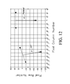
- FIG. 12 shows the results on one camera image of a 15 degree yaw movement (about the z-axis), according to some embodiments of the invention.
- FIGS. 13A and 13B shows how two cameras are able to monitor precisely a pitch movement (about the y-axis), according to some embodiments of the invention.
- FIGS. 14A and 14B show how a roll movement (about the x-axis) is monitored, according to some embodiments of the invention.
- FIG. 15 shows how x-axis translation (positive toward the top of the patient's head) is monitored on one camera, according to some embodiments of the invention.
- FIGS. 16A and 16B shows the effect of y-axis translation (positive to the patient's right side) as monitored on the two cameras, according to some embodiments of the invention.
- FIGS. 17A and 17B show the effect of z-axis translation (toward the ceiling), according to some embodiments of the invention.
- FIGS. 18A and 18B show the effect of simultaneous pitch and x-axis and z-axis translation, according to some embodiments of the invention.
- FIGS. 19A and 19B show the effect of simultaneous roll and y-axis and z-axis translation, according to some embodiments of the invention.
- FIGS. 20A and 20B display features of an iteration technique utilized to precisely monitor head movement utilizing the camera images of the precision optical target, according to some embodiments of the invention.
- FIG. 20C is a flow diagram of an iterative process for tracking movement.
- FIG. 21 is a block diagram depicting an embodiment of a computer system configured to implement one or more embodiments of the methods, devices, and systems described herein.
- FIGS. 22A and 22B show techniques for camera calibration, according to some embodiments of the invention.
- FIG. 23 is an embodiment of a schematic diagram illustrating a therapeutic applications connected to one or more marker tracking systems.
- FIG. 24 is a flowchart depicting an embodiment of a process for controlling the application of a therapeutic therapy based on coordinate data generated from one or more tracking systems.
- FIG. 25 is an embodiment of a schematic diagram illustrating a therapeutic applications connected to a marker tracking system.
- FIG. 26 a flowchart depicting an embodiment of a process for controlling the application of a therapeutic therapy based on coordinate data generated from a tracking system.
- FIGS. 27A-27G illustrate a laboratory configuration testing an embodiment of the concepts described herein.
- diagnostic technologies and therapeutic technologies it can be advantageous to track for patient movement with a high degree of accuracy.
- Such high accuracy tracking can improve the imaging quality obtained and produced by diagnostic equipment, such as imaging technologies.
- patient movement tracking technology can improve the application of patient therapies, such as radiation treatment, proton treatment, and the like.
- therapeutic technologies can apply therapies only to the targeted tissue and avoid healthy surrounding tissue.
- the embodiments disclosed herein relate to a patient motion tracking system that can track patient movement with translation accuracies of about 0.1 mm and angle accuracies of about 0.1 degrees.
- the system can be configured to utilize a non-stereo approach to determining the 6 degrees of freedom movement of the patient.
- the system can comprise two cameras that are positioned orthogonal and perpendicular on a single plane.
- the two cameras need not be in a single plane, but are positioned such that the two cameras are not viewing the target from generally the same direction.
- the system can be configured to compare the appearance of the target on one camera with the other camera while not accounting for which pixel number they fall on in either camera. By comparing the appearance of the target between the two cameras, the system can be configured to extract the 6 degrees of freedom movement on a very small target.
- the system can be configured to extract the movement data based on analyzing the images of the target from the two cameras in order to generate a predicted value for at least one of the variables in the 6 degrees of freedom.
- the system can be configured to analyze the image of the target and predict a value for the pitch.
- the system can then be configured to compare the predicted value to the value of the particular variable with that which is shown in the actual image of the target.
- the system can be configured to repeat this process using an iterative approach to continuously improve the predicted value of one of the variables in the 6 degrees of freedom.
- the system can be configured to perform this iterative process for each variable in the 6 degrees of freedom.
- the system can be configured to track patient movement in order to feed such movement data to an MRI scanner such that the MRI scanner can adjust the focus and position of the scanner in order to produce a clear MRI image of the patient.
- the system can be configured to connect to therapeutic technologies.
- the system can be configured to track patient movement in order to direct a therapeutic radiation beam at a diseased tissue region while avoiding surrounding healthy tissue.
- Radiotherapy there are various technologies for therapeutic radiation and other therapeutics.
- it can be advantageous in radiation therapy, proton therapy, or other therapies to dynamically apply the radiation to a targeted area in order to account for patient movement.
- Patient movement can include respiration, twitches or any other voluntary or involuntary movements of the patient.
- radiation therapy, proton therapy, and any other kind of therapy can be applied in a more targeted way, thereby allowing surrounding healthy tissue to be avoided and/or unharmed.
- the systems disclosed herein can be adapted and configured to track patient translations with accuracies of about 0.1 mm and angle accuracies of about 0.1 degrees in order to better apply radiation therapy, proton therapy, or any other therapy to the targeted tissue or area of the body.
- a system can be configured to utilize optical tracking based on the methods disclosed herein in order to track patient movement and/or or another device, for example, electronics packages that are configured to identify fiducial markers implanted inside a patient.
- the system can be configured to utilize the electronics package in order to identify the location of the fiducial markers within the patient. By identifying the location of the fiducial markers, the system needs to identify the location of the electronics package in order to determine the location of the fiducial markers with respect to a scanner and/or a therapeutic equipment device.
- the patient tracking movement system can be utilized to track periodic involuntary movement of the patient, such as breathing.
- the system can be configured to apply a radiation therapy, a proton therapy, or the like during strategic moments when the target tissue is in a certain position while the patient's involuntary movements continue.
- the system can be configured to track not only normal breathing movement of the patient, but also the system can be configured to track irregular movement of the patient caused by patient activity or based on diseased tissue of the patient. For example, when a patient is running, the ribs of the patient have a larger egression that the system can track in order to continuously identify a target tissue area.
- the patient may be suffering from COPD or other breathing disorder or diagrammatic issues.
- the patient could be suffering from theurofusion, which is water outside the lung that prevents the patient from breathing or a tumor is irritating a lung region thereby preventing normal breathing.
- the system can be configured to track such irregular patient movements due to such conditions.
- the radiation beam generator In order to apply a therapy, such as radiation therapy, the radiation beam generator must determine the location of the electronics package relative to the beam generator in order to properly direct the radiation therapy to the targeted tissue. Accordingly, it is necessary to track the position of the electronics package relative to the radiation beam generator or other therapeutic equipment. It can be advantageous to track the position of the electronics package with a high degree of accuracy in order to better target the desired tissue.
- the electronics package In systems where the electronics package is configured to track the location of fiducial markers implanted within the patient, such systems have two possible sources of error. One source of error can be derived from tracking the position of the fiducial markers using the electronics package and the second source of error can be derived from tracking the position of the electronics package relative to the therapeutic equipment generator. Accordingly, it can be advantageous to identify the position of the electronics package with a high degree of accuracy in order to avoid compounding the sources of error.
- FIG. 1A is an embodiment of a schematic diagram illustrating a front view of a medical imaging scanner 104 as part of a motion compensation system 100 .
- FIG. 1B is a schematic diagram illustrating a side view of the medical imaging scanner 104 as a part of the motion compensation system 100 of FIG. 1A .
- the motion compensation system 100 can be used to, for example, track the motion of a patient undergoing a medical imaging procedure to enable a medical imaging scanner to adjust or otherwise compensate for that motion, to reduce or eliminate motion artifacts in the resulting medical images.
- the motion compensation system 100 illustrated in FIGS. 1A and 1B comprises a motion tracking system 102 , a scanner 104 , a scanner controller 106 , two detectors 108 , and an optical marker or target 110 .
- the optical marker 110 is shown attached to a patient 112 positioned on a table 114 of the medical imaging scanner 104 .
- the scanner 104 can be, for example, a magnetic resonance imaging scanner.
- the optical marker 110 can be configured as further described below, for example as described in reference to FIG. 2A .
- the optical marker 110 is configured to be viewable by each of the two detectors 108 .
- the detectors 108 can be, for example, digital cameras capable of acquiring images of the optical marker 110 and transmitting those images to the motion tracking system 102 .
- each of the detectors 108 is configured to view the optical marker 110 from along a different line of sight. This can be helpful, for example, to enable the motion tracking system 102 to analyze two dimensional images of the optical marker 110 from different vantage points to help in locating the optical marker 110 to estimate patient motion or pose.
- the detectors 108 each are configured to view the optical marker 110 along a line of sight 120 separated from each other by an angle 122 . In this embodiment, the angle 122 is approximately 90 degrees.
- 90 degrees is an optimal angle to enable maximum differentiation of in plane and out of plane motion of the optical marker 110 , as further described below with reference to FIGS. 8A and 8B .
- that detector may have a harder time distinguishing motion of the optical marker 110 than the other detector.
- the other detector may relatively easily detect the motion of the optical marker 110 , as the motion is perpendicular to that detector's line of sight.
- the angle 122 may be referred to as a scissor angle.
- the scissor angle is the angle at which the detectors 108 are directly viewing the marker 110 .
- the scissor angle may be a virtual angle, as the lines of sight from the detectors to the marker may be redirected by mirrors and/or other means, such as beam splitters, prisms, fiber optics, and/or the like. In that case, the scissor angle is the apparent angle at which the detectors are viewing the marker. For example, as further described below with reference to FIGS.
- the detectors 108 of the motion compensation system 440 are positioned with lines of sight collinear to each other near the detectors. However, mirrors are utilized to redirect the lines of sight such that a virtual scissor angle of approximately 90 degrees is accomplished near the marker.
- Mirrors or other devices used to redirect a line of sight have both advantages and disadvantages.
- disadvantages of mirrors include that they could potentially vibrate, potentially introducing error into the object orientation determination process.
- the further away a mirror is from a detector generally the larger the mirror needs to be to enable an equivalent range of vision. Accordingly, it can be advantageous to position a mirror relatively close to a detector to enable the mirror to be relatively small.
- One advantage of using mirrors or other sight line redirection methods is that a virtual scissor angle can be configured to be closer to an optimal scissor angle of 90°, even when a particular medical imaging scanner configuration may not allow for detectors that are positioned to directly view a marker using a 90° scissor angle.
- a digital camera may include conductive components and/or a wire leading to the detector may include conductive components. When a digital camera and/or its wire are within the medical imaging envelope, they may introduce artifacts into MRI images.
- FIGS. 1A-1B The embodiment of a motion compensation system 100 illustrated in FIGS. 1A-1B is not shown to scale, but is rather show at a scale that helps facilitate illustration of the system. Other figures, such as is shown in FIGS. 4A-4K , are also not shown to scale. Additionally, most embodiments illustrated in these figures and described in this specification comprise a motion compensation system operating in real time or substantially in real time to correct a scanner for motion of a patient or object. However, in other embodiments, a motion compensation system can be configured to operate by processing images using post-processing after they have been created by a scanner to remove any motion artifacts.
- the detectors 108 are positioned at an angle of approximately 90 degrees along a transverse axis of the scanner 104 , but are positioned at an angle of approximately 0 degrees along a longitudinal axis of the scanner 104 , as shown in FIG. 1B .
- the detectors 108 are configured to be positioned directly above a nominal home position of the optical marker 110 , as shown in FIG. 1B .
- the detectors may be setup in various other configurations, as further described below.
- FIGS. 2A-2C illustrate one embodiment of an optical marker 110 used with a motion compensation system.
- FIG. 2A is a front view of the optical marker 110 .
- FIG. 2B is a perspective view of the optical marker 110 of FIG. 2A in use with a patient 112 .
- FIG. 2C is a front view of the optical marker of FIG. 2A , the optical marker shown next to a U.S. penny 212 for scale.
- the optical marker 110 comprises a pattern 202 that defines a reference shape.
- the pattern 202 defines a reference shape of an equilateral triangle having sides of approximately 0.5 inches.
- a reference point locater 204 At each vertex of the equilateral triangle reference shape is a reference point locater 204 .
- each reference point locator 204 comprises a series of alternating black and white (or dark and light) elliptical shapes, with a centroid of the reference point locater 204 being positioned at the vertex of the equilateral triangle reference shape.
- reference point locators can take various forms, as long as the reference point locators are able to be detected and analyzed by a motion tracking system to determine important points, inflection points, critical points, or vertex points of a reference shape.
- the reference point locators 204 are elliptical in shape and positioned such that they are configured to be visible as a circular pattern from a 45 degree viewing angle. This can be advantageous, because, when used in a system such as the example illustrated in FIGS. 1A and 1B , where the detectors 108 are viewing the optical marker 110 along a 45 degree sight line, any images of the optical marker 110 at the nominal home location will illustrate the reference point locators 204 as circles. Then, if the marker is moved, that motion will result in a non-circular elliptical pattern showing up on the images of the optical marker. Further description of the optical marker configuration is given below.
- FIG. 2B illustrates that the optical marker 110 can, in some embodiments, be configured to mount to a patient's top teeth. This can be advantageous to retain or affix the optical marker 110 in a rigid or substantially rigid location with respect to the patient's skull. As described below, various methods and devices may be used to attach an optical marker to a patient or other object of interest.
- FIG. 3A is a block diagram depicting an embodiment of a motion compensation system 300 .
- the motion compensation system 300 can be similar to, for example, the motion compensation system 100 illustrated in FIGS. 1A and 1B .
- the motion compensation system 300 comprises two detectors 108 , a motion tracking system 102 , a scanner 104 , and a scanner controller 106 .
- the scanner 104 is a medical imaging scanner, such as an MRI machine.
- the scanner controller 106 can be configured to operate and control the scanner 104 , such as by adjusting the scanner 104 in real time or substantially real time to correct for motion of the object or patient being scanned.
- the scanner controller 106 can adjust for motion based on motion tracking data or information received from the motion tracking system 102 .
- the detectors 108 can comprise, for example, digital cameras. Although in this embodiment there are two detectors 108 , various other embodiments may utilize more or fewer detectors based on the application.
- an embodiment of a motion compensation system may comprise more detectors to increase accuracy of motion tracking and/or to add redundancy to a motion compensation system.
- a motion compensation system may comprise four detectors, with motion tracking being performed only using two of the detectors at any one time. This may be advantageous, for example, when obstructions may hide an optical marker from view of one or more detectors depending on the position of the object being tracked.
- a detector may be an infrared camera configured to view a target or marker viewable by an infrared camera.
- the detectors may comprise laser detectors, sonar detectors, radar detectors, and various other types of detectors capable of locating a marker and/or creating a two dimensional digital image or representation of a marker.
- the motion tracking system 102 comprises a tracking engine 304 , a calibration engine 306 , a controller interface 308 , and a motion database 310 .
- the motion database 310 can be configured to store motion tracking information, such as object pose estimates created by the tracking engine 304 .
- the motion database 310 can be configured to be persistent storage to store the motion information for later retrieval and usage after the completion of an imaging scan.
- the motion database 310 comprises a short term memory or buffer or cache to store object pose estimates just temporarily until they are included in motion data and sent to the scanner controller 106 by the controller interface 308 .
- the calibration engine 306 can be configured to calibrate the motion compensation system.
- the calibration engine 306 comprises a calibration database 316 , a detector calibration filter 318 , and a target calibration filter 320 .
- the calibration engine 306 can be configured to calibrate the system at initial startup or initial system assembly, with calibration not being needed for later operation of the motion compensation system 300 .
- the calibration engine 306 is utilized for at least some calibration procedures during some or all motion tracking procedures.
- the detector calibration filter 318 can be configured to calibrate the detectors 108 to the motion compensation system.
- the detector calibration filter 318 can be configured to calibrate the detectors by enabling a manufacturer or assembler of the motion compensation system to input information specific to each detector 108 , such as focal length, resolution, etc. In some embodiments, the detector calibration filter 318 can be configured to automatically determine some or all of the parameters needed to calibrate a detector 108 . The parameters determined in calibration of the detectors can be stored in the calibration database 316 for later use by the tracking engine 304 .
- the target calibration filter 320 can be configured to calibrate the system to one or more specific targets or markers.
- the target calibration filter 320 can be configured to, upon initial startup of a motion tracking routine, analyze images received from the detectors 108 to determine a region of interest in the images where it is most likely that the optical marker exists. This information can be stored in the calibration database 316 .
- This initial calibration upon startup of a motion tracking routine can, for example, help to speed up a tracking routine.
- the tracking engine 304 comprises a marker location filter 312 and an objection orientation filter 314 .
- the tracking engine 304 can be configured to track the location of one or more optical markers during an imaging scan and to determine an estimate of the pose of the object or patient being scanned.
- the marker location filter 312 can be configured to analyze images from the detectors 108 to determine locations of reference points of an optical marker in the 2D images from the detectors.
- the marker location filter 312 can be configured to analyze these images to determine both the locations of these points and the orientation of the reference shape or shapes formed by the reference points.
- the object orientation filter 314 can be configured to utilize the marker location information from the marker location filter 312 to convert that information into an estimated object pose.
- the object orientation filter 314 can be configured to then pass the estimated object pose information off to the motion database 310 and/or the controller interface 308 for use by the scanner controller 106 .
- the tracking engine 304 can utilize various processes or algorithms in determining the location of marker reference points and converting this information into estimated object poses. Some examples of these processes or algorithms are described in more detail below. However, various other processes or algorithms can be used with the techniques disclosed herein.
- the controller interface 308 can be configured to convert object pose information into a coordinate system of the imaging scanner and to pass this information to the scanner controller 106 .
- the controller interface 308 comprises a coordinate system converter 322 and a motion data feed generator 324 .
- the coordinate system converter 322 can be configured to take the estimated object pose information from the tracking engine 304 and/or the motion database 310 and convert that object pose information from the motion tracking system's coordinate system into the scanner's coordinate system.
- the motion data feed generator 324 can be configured to take the converted object pose information and transmit it to the scanner controller 106 . In some embodiments, the motion data feed generator 324 is configured to transmit object pose information to the scanner controller 106 immediately as the object pose information becomes available.
- the motion data feed generator 324 can be configured to sync the timing of the motion tracking system 102 with the scanner controller 106 .
- the motion tracking system 102 may be configured to acquire images and estimate object poses at a rate of approximately 100 hertz.
- the scanner controller 106 and scanner 104 may, on the other hand, be configured to take scans at a different rate.
- the motion data feed generator 324 can therefore be configured to match the motion tracking system's output speed to the scanner and/or scanner controller speed. In some embodiments, this may involve caching converted object pose information until it is necessary to send that information to the scanner controller 106 .
- the motion data feed generator 324 is configured to obtain multiple object poses and to combine these, such as by averaging, before sending them to the scanner controller 106 . In other embodiments, the motion data feed generator 324 is configured to transmit only the latest object pose estimate to the scanner controller 106 . In some embodiments, the motion data feed generator 324 is configured to retransmit the last object pose estimate sent to the scanner controller 106 if the motion tracking system 102 has not generated a new object pose estimate since the last time the motion data feed generator 324 sent an object pose estimate to the scanner controller 106 .
- the motion compensation system 300 illustrated in FIG. 3A is disclosed in a system configured to adjust a scanner in real time or substantially in real time to adjust for patient motion
- other embodiments may utilize a motion compensation system to adjust acquired images after the scanning process to remove motion artifacts.
- the scanner can be configured to adjust for motion in real time and to post process images to remove any remaining motion artifacts based on the tracked motion.
- the motion compensation system 300 illustrated in FIG. 3A illustrates the motion tracking system 102 as being a separate system from the scanner controller 106
- the motion tracking system 102 can be integrated into the scanner controller 106 .
- a medical imaging scanner can be produced with an integrated scanner controller comprising features to both control the scanner and to track object or patient motion during scan.
- FIG. 3B is a block diagram depicting another embodiment of a motion compensation system 301 .
- the motion compensation system 301 illustrated in FIG. 3B is similar to the motion compensation system 300 illustrated in FIG. 3A .
- the motion compensation system 301 utilizes a different tracking engine 334 than the tracking engine 304 illustrated in FIG. 3A .
- the tracking engine 334 comprises a reference point filter 336 , a principal quantities generator 338 , a reference frame translator 340 , an error filter 342 , and a convergence filter 344 .
- the components of the tracking engine 334 can be configured to operate to track the motion of an object or patient using, for example, the process flow described below with reference to FIG. 7C .
- the reference point filter 336 can be configured to, among other things, analyze two dimensional images of an optical marker to determine the locations of the reference points of that marker.
- the principal quantities generator 338 can be configured to analyze the reference shape formed by the reference points, as viewed by two or more detectors, to determine a number of principal quantities, such as six, that can be used to help describe or define the 3D position and orientation of the optical marker.
- the reference frame translator 340 can be configured to convert between the two dimensional reference frame of each detector and the three dimensional frame of the motion tracking system.
- the error filter 342 can be configured to analyze differences in principal quantities based on the visualized reference points and based on estimates of an object pose to determine an amount of error between the two.
- the convergence filter 344 can be configured to perform iterative processes to reduce an amount of error in an object pose estimate until an object pose estimate has an acceptable amount of error.
- the tracking engine 334 can be configured to communicate with the motion database 310 , calibration engine 306 , and controller interface 308 similarly to as described above with respect to the motion compensation system 300 of FIG. 3A .
- FIG. 4A is another embodiment of a schematic diagram illustrating a front view of a medical imagine scanner 104 as part of a motion compensation system 400 .
- FIG. 4B is a schematic diagram illustrating a side view of the medical imaging scanner 104 as part of the motion compensation system 400 .
- the motion compensation system 400 is similar to the motion compensation system 100 illustrated in FIGS. 1A and 1B .
- the motion compensation system 100 as described above, comprises two detectors 108 positioned at a 90 degree angle to each other along a transverse axis of the scanner 104 .
- the detectors 108 are positioned at a 90 degree angle 422 to each other along the longitudinal axis of the scanner 104 .
- the detectors 108 of the motion compensation system 400 are still configured to view the optical marker 110 along two different lines of sight 420 .
- the motion compensation system 400 illustrates that the detectors 108 can be positioned in various ways, as long as each detector 108 views the optical marker 110 along a different line of sight.
- the angle 422 as described above with respect to the angle 122 , can vary and be larger or smaller. In some embodiments, the angle 422 can be between 100 degrees and 70 degrees. In other embodiments, the angle 422 can be 30 degrees.
- FIG. 4K illustrates a motion compensation system 490 similar to the motion compensation system 400 , except that the angle 422 is 30 degrees. In other embodiments, the angle can be various other angles, as long as the two lines of sight 420 are different.
- FIG. 4C is another embodiment of a schematic diagram illustrating a front view of a medical imaging scanner 104 as part of a motion compensation system 430 .
- FIG. 4D is a schematic diagram illustrating a side view of the medical imaging scanner 104 as a part of the motion compensation system 430 .
- the motion compensation system 430 is similar to the motion compensation system 100 illustrated in FIGS. 1A and 1B .
- the motion compensation system 430 further comprises a head cage or head coil 432 configured to be positioned around a patient's head.
- a head cage 432 can be utilized and positioned around the patient's head.
- the head cage can make it more difficult for a detector 108 to image the optical marker 110 if the detectors 108 were mounted to the bore of the scanner body 104 .
- the motion compensation system 430 comprises two detectors 108 mounted to the head cage instead of the scanner body.
- the detectors 108 and motion tracking system 102 are configured to operate similarly to as described above.
- the term head cage as utilized herein may be used to describe a device configured to help position the head of a patient during an MRI scan.
- the term head cage may also refer to a head coil device configured to wrap around a patient's head to perform MRI scanning functions.
- FIG. 4E is another embodiment of a schematic diagram illustrating a front view of a medical imaging scanner 104 as part of a motion compensation system 440 .
- FIG. 4F is a schematic diagram illustrating a side view of the medical imaging scanner 104 as a part of the motion compensation system 440 .
- the motion compensation system 440 is similar to the motion compensation system 430 illustrated in FIGS. 4C and 4D .
- there can be limited space within the bore of a scanner 104 In those cases, it can be difficult to position detectors 108 to have a direct line of sight between their lens and the optical marker 110 .
- the motion compensation system 440 comprises two detectors 108 positioned flat against the head cage 432 with a line of sight 120 being through a mirror 442 to the optical marker 110 .
- the mirrors 442 enable an indirect line of sight to make the system more compact but to still enable viewing of the optical marker 110 from along two different lines of sight 120 .
- this embodiment illustrates the use of mirrors with detectors mounted to a head cage, various other embodiments may use mirrors and/or detectors attached to the scanner body, the head cage, or any other location, as long as the detectors can view the optical marker through the mirrors.
- multiple mirrors are used to redirect the line of sight 120 multiple times.
- a detector 108 may be positioned outside of the scanner and have its line of sight pass through one or more mirrors positioned within the scanner to image the optical marker.
- the motion compensation system 440 comprises mirrors to redirect the lines of sight
- other methods of redirecting a line of sight may be used, alone or in combination with mirrors.
- fiber optics or prisms may be used to redirect a line of sight and create a virtual scissor angle.
- FIG. 4G is another embodiment of a schematic diagram illustrating a front view of a medical imaging scanner 104 as part of a motion compensation system 450 .
- the motion compensation system 450 is similar to the motion compensation system 100 illustrated in FIGS. 1A and 1B .
- the motion compensation system 450 comprises two optical markers 110 .
- each of the two optical markers 110 is positioned to be directly in the line of sight of one of the detectors 108 .
- multiple optical markers 110 may be utilized and positioned in other ways.
- multiple optical markers may be positioned at various rigid or substantially rigid portions of the object being imaged.
- one optical marker 110 may be positioned on a patient's top teeth, while one or more other markers may be positioned on a patient's forehead.
- Optical markers may also be positioned at locations that are not rigid or substantially rigid.
- an optical marker may be attached to a patient's skin.
- the marker may at times move in relation to the object being scanned, which can introduce inaccuracies into a medical imaging scan.
- a motion compensation system can be configured to differentiate between movements of the object being scanned, such as a patient's head, and skin movement, which may not correlate to actual movement of the object being scanned.
- the system can be configured to compare the positioning of two or more markers relative to themselves in order to differentiate between head movement and skin movement.
- multiple optical markers 110 can have various benefits. For example, multiple markers may be used for redundancy, in case one or more markers is not currently visible to one or more detectors based on the current object's pose. Another advantage is that multiple optical markers can be analyzed simultaneously by the motion tracking system 102 to obtain multiple object pose estimates. Those multiple object pose estimates can then be combined to generate a single more accurate estimate. For example, the multiple estimates can be averaged to come up with an average estimate. In another example, there may be a measure of margin of error for each estimate and the estimates may be combined using a weighted average based on the margin of error. In other embodiments, only the most accurate estimate is used and other estimates are dropped.
- FIGS. 4H-4J illustrate additional embodiments of motion compensation systems configured to use indirect lines of sight. Given that many medical imaging systems have limited space within the bore of the device, it can be advantageous to position detectors to be generally flat against a bore of the device or flush within the bore of the device.
- the embodiment of a motion tracking system 460 shown in FIG. 4H illustrates a system wherein two optical detectors 108 are positioned flat against a bore of the medical imaging scanner 104 . In this embodiment, the detectors 108 are positioned facing each other along a longitudinal axis of the bore.
- Two mirrors 442 are positioned relatively close to the detectors to redirect their lines of sight 120 toward the optical marker 110 .
- the scissor angle is significantly smaller than 90 degrees. However, in other embodiments, the detectors and/or mirrors may be positioned differently to increase or decrease the scissor angle.
- the motion compensation system 470 illustrated in FIG. 4I is similar to the motion compensation system 460 illustrated in FIG. 4H .
- the motion compensation system 470 comprises two detectors 108 and two mirrors 442 mounted within the medical imaging scanner 104 such that they do not protrude into the bore of the scanner 104 .
- the scanner 104 body can comprise openings to enable the lines of sight 120 to pass from the marker 110 to the detectors 108 .
- detectors may be positioned on a surface of the scanner bore, partially within the body of the scanner, fully within the body of the scanner, and/or the like.
- One determining factor of whether detectors can be mounted within a scanner body and/or whether any of the detector must protrude beyond the scanner body is the size of the detectors and the space available within the scanner body. More space available within the scanner body and/or smaller detectors may enable more or all of the detectors to be positioned within the scanner body.
- FIG. 4J illustrates a motion compensation system 480 .
- the motion compensation system 480 is similar to the motion compensation system 460 illustrated in FIG. 4H .
- the motion compensation system 480 comprises a head cage 432 , and the detectors 108 and mirrors 442 are mounted opposite each other on opposite ends of the head cage 432 , rather than being mounted to the bore of the scanner.
- the detectors 108 may be mounted in various positions, not necessarily facing each other.
- both detectors 108 may be positioned on the same side of the head cage 432 .
- each of the two detectors 108 is configured to view the optical marker 110 along a line of sight 120 viewing the optical marker 110 along a different angle relative to the marker.
- the line of sight 120 on the left-hand side is at a shallower angle than the line of sight 120 on the right-hand side.
- the positioning of the detectors, the optical marker, and/or the mirrors may be adjusted to adjust the angles of each of the lines of sight relative to the marker and/or to adjust the scissor angle.
- FIGS. 4L-4N illustrate additional embodiments of schematic diagrams of motion compensation systems.
- Each of the motion compensation systems illustrated in FIGS. 4L-4N comprise one or more detectors 108 , multiple lines of sight 120 , one or more optical markers 110 , and a head cage or head coil 432 .
- Some embodiments also comprise one or more mirrors 442 and one or more beam splitters 444 .
- the beam splitters 444 comprise prisms.
- each of the motion compensation systems illustrated in FIGS. 4L-4N include two optical markers 110 , the concepts disclosed herein may be applied to a system using any number of optical markers. In some embodiments, the motion compensation system uses two optical markers to add redundancy to the system.
- one optical marker may at some times have lines of sight to it blocked by, for example, a portion of the head coil 432 .
- the optical markers can be positioned such that when one optical marker's line of sight is obstructed, the other optical marker is still able to be imaged by one or more detectors 108 .
- the optical markers 110 illustrated in FIGS. 4L-4N comprise a checkerboard pattern, the optical markers 110 may also or alternatively comprise a pattern similar to the pattern illustrated in the optical marker 110 shown in FIG. 2A .
- the embodiment illustrated in FIG. 4L comprises four detectors 108 imaging two optical markers 110 .
- Each of the optical markers 110 is simultaneously imaged by two of the optical detectors 108 along two different lines of sight 120 .
- the embodiment illustrated in FIG. 4M is similar to the embodiment illustrated in FIG. 4L , except the number of detectors is reduced by two.
- each of the two detectors 108 is configured to simultaneously image both of the optical markers 110 .
- the system is configured to accomplish this by splitting a sight line from a detector through a beam splitter 444 and also redirecting the resulting multiple sight lines through mirrors 442 .
- a resulting digital image from the optical detector 108 may comprise digital representations of both optical markers 110 (or potentially only one optical marker if, for example, one of the lines of sight is blocked).
- the motion compensation system can be configured to analyze the representations of each of the optical markers separately, even if the representations are included in the same digital image.
- FIG. 4N is similar to the embodiment illustrated in FIG. 4M , except only one optical detector 108 is utilized.
- the sight line of the optical detector 108 is split at beam splitter 444 into two lines of sight 120 , with each line of sight being directed toward one of the two optical markers 110 .
- a digital image resulting from the detector 108 may comprise representations of both optical markers 110 (or potentially only one optical marker if, for example, one of the lines of sight is blocked).
- FIGS. 5A-5E illustrate various options for mounting an optical marker to an object.
- FIG. 5A is a front perspective view of an embodiment of an optical marker connected to a mounting portion 514 .
- FIG. 5B is a side perspective view of the optical marker 110 of FIG. 5A mounted to the mounting portion 514 .
- the optical marker 110 illustrated in FIGS. 5A and 5B is similar to the optical marker 110 illustrated in FIGS. 2A-2C .
- This embodiment is configured to attach to a patient's top teeth.
- the mounting portion 514 comprises a front portion 516 , a back portion 518 , and a trough 520 between the front portion 516 and back portion 518 .
- the front portion 516 is configured to pass in front of a person's top teeth, while the back portion 518 is configured to pass behind a user's top front teeth.
- the trough 520 is configured to conform or substantially conform to the user's teeth.
- the mounting portion 514 is configured to be shaped to a specific user to enhance the fit and/or rigidity of the optical marker 110 .
- the mounting portion 514 can be configured to be softened and placed onto the user's teeth and then hardened.
- the mounting portion 514 comprises a polymer that softens when heated and hardens when cooled.
- the mounting portion 514 may, for example, be heated in warm water and then placed in the user's mouth to set.
- the mounting portion 514 comprises an ultraviolet curable polymer.
- the mounting portion 514 can be placed on a user's teeth in a soft condition and then cured to a hardened condition using an ultraviolet light.
- the mounting portion 514 can be configured to have an adhesive or moldable polymer material placed into the trough 520 to conform to or adhere to a user's teeth.
- the mounting portion 514 can be connected to the optical marker 110 using the connection portion 522 .
- the optical marker 110 and mounting portion 514 are an integral inseparable unit.
- the connection portion 522 enables the optical marker 110 to be detached and reattached to the mounting portion 514 . This may be advantageous, for example, to enable the mounting portion 514 to be shaped to a user's teeth without the optical marker 110 mounted to it.
- the connection portion 522 is relatively small and enables the optical marker 110 to be relatively close to the mounting portion 514 .
- the connecting portion 522 is longer and enables the optical marker 110 to be positioned further away from the object being tracked.
- connection portion 522 is configured to position the optical marker 110 such that it will not be covered by a patient's lips when the mounting portion 514 is positioned over the user's teeth.
- the mounting portion 514 comprises an additional flap configured to be positioned over a user's lip to keep their lip from blocking the optical marker 110 .
- an optical marker can be internally lighted.
- an optical marker can include one or more LED lights or the like inside the optical marker to uniformly or substantially uniformly light the optical marker or individual reference points. Illumination of an optical marker can be advantageous to enable a detector to more clearly image the optical marker and to make it easier for a motion tracking system to distinguish the reference points on the optical marker and/or to distinguish centroids of the reference points.
- the detectors and/or another part of a motion compensation system includes lights configured to illuminate the optical marker.
- the lighting can be infrared lights.
- an optical marker can be configured to glow in the dark to enable enhanced illumination without using auxiliary lighting.
- an optical marker can be configured to be charged with light by being placed in front of a light source for a period of time, after which the optical marker will glow for a period of time.
- FIG. 5C is a top view of another embodiment of an optical marker 110 connected to a mounting portion 524 .
- FIG. 5D is a top view of yet another embodiment of an optical marker 110 connected to a mounting portion 534 .
- the mounting portion 524 illustrated in FIG. 5C is a relatively narrow mounting portion comprising a front portion 526 , back portion 528 , and a trough 530 therebetween.
- the mounting portion 534 illustrated in FIG. 5D is, however, a relatively wide mounting portion.
- the mounting portion 534 comprises a front portion 536 , a back portion 538 , and a trough 540 therebetween.
- the embodiments illustrated in FIGS. 5C and 5D illustrate that mounting portions can take various shapes.
- the mounting portion 524 is similar in size to the mounting portion illustrated in FIGS. 5A and 5B .
- This mounting portion may engage only a couple teeth of the patient.
- the mounting portion 534 illustrated in FIG. 5D comprises a more U-shaped mounting portion configured to engage several teeth of the patient.
- the mounting portion 534 may be in some embodiments similar in design to a mouthguard typically used by athletes.
- the mounting portions 524 and 534 are both connected to an optical marker 110 using a connection portion 532 .
- FIG. 5E is a perspective view of an embodiment of an optical marker 110 connected to a patient 112 .
- the optical marker 110 is attached to a strap 550 configured to go around the patient's head to help retain the optical marker 110 in position.
- the optical marker 110 also is attached to a mounting portion, such as the mounting portions described above configured to attach to a patient's teeth.
- Various embodiments of mounting an optical marker to a patient have been described. However, various other methods may be used such as, but not limited to, adhesives, tape, tattoos, paint, and/or the like.
- FIG. 6A is a perspective view of an embodiment of an optical marker 610 using distributed reference points 614 and 612 .
- the optical marker 610 comprises three reference points 612 and 614 comprising elliptical shapes and forming a triangular reference shape when viewed together.
- the optical marker 610 is a distributed optical marker, in that the reference points are not part of the same physical object.
- the reference point 612 is on a substrate attached to the patient's top teeth, similar to as described above.
- the other two reference points 614 are stickers attached to the patient's forehead above his or her eyes.
- One advantage of the configuration illustrated in FIG. 6A is that detectors that have a lower resolution, and are therefore cheaper, may be used.
- Another advantage is that smaller movements of the patient 112 may be able to be more accurately detected in images of the optical marker 610 .
- a disadvantage of the configuration shown in FIG. 6A is, however, that the three reference points are not rigid with respect to each other. For example, if the patient 112 moves his or her skin over the forehead, the reference points 614 may move with respect to the reference point 612 attached to his or her teeth.
- the motion tracking system can be configured to analyze relative motion of the reference points to determine whether the motion is due to local skin motion or deformations or actual patient movement.
- each reference point may be positioned on a block, substrate, or other backing, with the backing being affixed or attached to the patient or object being tracked.
- the reference point 612 illustrated in FIG. 6A is shown attached to a substantially rigid backing.
- the reference points 614 are illustrated as individual points not having a backing and being directly affixed to the patient's forehead.
- the reference points 614 may also be attached to a backing, block, or other backing to help in attaching the reference point to the object and/or to reduce any flexing of the reference point and/or to keep the reference point shape flat.
- an optical marker and/or an individual reference point can be configured to attach to an object being tracked using a variety of means.
- double-sided surgical tape can be utilized to attach a marker to an object.
- Other adhesives may also be used.
- Other mechanical affixing means may also be used, such as other types of tape, clamps, straps, fasteners, and/or the like.
- reference points and/or markers may be positioned at various locations.
- a reference point or marker may be positioned at a patient's nose, cheeks, chin, temples, ears, and various other locations as long as the reference point or marker will be visible to a detector during at least a portion of the object's range of motion, either through a direct or indirect line of sight.
- the reference points illustrated in FIG. 6A are spaced relatively far apart from each other, in some embodiments, the reference points may be spaced relatively close together, although still not attached to the same backing or mounting material.
- the reference points may be located and spaced a similar distance apart as shown in the optical marker 110 illustrated in FIG. 2B , even if the three reference points are each attached to a different backing material or mounting portion.
- the three reference points can be spaced in a similar fashion to the optical marker 110 illustrated in FIG. 2B , except the reference points are each a separate object adhered to the patient and not connected to each other.
- obstructions may exist that could potentially block a line of sight to an optical marker.
- a head cage or head coil such as is shown in FIG. 9A may have bars or other portions that may obstruct a line of sight to a marker.
- a marker or reference point can be positioned on an object at a location that eliminates or reduces any blockage of a line of sight to the marker.
- mirrors or other devices configured to redirect a line of sight may be used to enable a detector to image a marker through a hole or opening in an obstruction such as a head cage or head coil.
- FIG. 6B is a perspective view of an embodiment of an optical marker 610 using distributed reference points 614 and 612 , and an embodiment of an optical marker 110 using integrated reference points 612 and 616 .
- the embodiment illustrated in FIG. 6B is similar to the embodiment illustrated in FIG. 6A , but utilizing two different-sized optical markers.
- the configuration in FIG. 6B utilizes the distributed optical marker 610 illustrated in FIG. 6A and the non-distributed optical marker 110 illustrated in FIG. 2B .
- Such a configuration can be advantageous to, for example, obtain the benefits of a larger marker 610 while counteracting some of the issues with a distributed marker by using the non-distributed marker 110 .
- a motion tracking system can be configured to track the larger marker 610 and/or the smaller marker 110 based on the motion the detectors are capturing. For example, if a system is concerned with local motion or twitching of the patient's forehead skin that may introduce inaccuracies into the system, the system may be configured to stop tracking utilizing the larger optical marker 610 when motion in a direction consistent with a localized motion of a marker 614 is detected. For example, if a marker 614 is imaged moving in a longitudinal direction, such as up and down with respect to the patient's head, this may be indicative of local skin motion and may introduce inaccuracies if tracking the optical marker 610 is used.
- a motion tracking system can be configured to track motion utilizing a larger distributed marker when motions not indicative of localized skin motion are detected, but to track using a smaller non-distributed marker when motions indicative of localized skin motion are detected.
- FIG. 6C is a perspective view of an embodiment of multiple optical markers 110 attached to an object being tracked, in this case the patient 112 .
- This embodiment illustrates that multiple complete optical markers 110 can be affixed to the same object.
- the optical markers are attached at the patient's top teeth and forehead, optical markers may be attached in addition to or in lieu of these locations at, for example, the cheeks, the temples, ears, chin, nose, below the eyes, and/or the like. Utilizing multiple optical markers may be advantageous to increase accuracy and/or redundancy.
- FIG. 7A depicts an embodiment of a process flow diagram illustrating an example of a motion compensation process.
- the process flow illustrated in FIG. 7A can be implemented by, for example, the motion compensation systems 300 or 301 illustrated in FIGS. 3A and 3B .
- the scanner starts an imaging scan.
- the motion compensation system starts its process.
- a tracking engine acquires marker images.
- the tracking engine 304 illustrated in FIG. 3A can be configured to acquire one image frame each from detector 1 and detector 2 .
- the tracking engine determines an object pose.
- the marker location filter 312 can be configured to determine two dimensional locations of marker reference points
- the object orientation filter 314 can be configured to estimate a three dimensional pose of the object being tracked using the two dimensional locations of the marker reference points.
- the tracking engine may store this information in the motion database shown at block 710 .
- the motion database shown at block 710 may be, for example, the motion database 310 illustrated in FIG. 3A .
- a controller interface generates motion data.
- the controller interface 308 illustrated in FIG. 3A can be configured to convert the object pose information into the scanner coordinate system and generate data for enabling the scanner controller to adjust for the motion.
- the controller interface transmits the motion data to a scanner controller.
- the scanner controller operates to adjust the scanner to compensate for the motion.
- the process varies depending on whether the imaging scan is complete. If the imaging scan is not complete, the process flow proceeds back to block 706 and proceeds as described above. If the scan is complete, the process flow proceeds to block 720 , and the motion compensation process is completed.
- FIG. 7B depicts another embodiment of a process flow diagram illustrating an example of a motion compensation process.
- a scanner starts the imaging process.
- a motion compensation system starts its process.
- this process may be implemented by the motion compensation system 300 illustrated in FIG. 3A .
- the motion tracking system is optionally calibrated.
- the target calibration filter 320 can be configured to determine a general location of the optical marker in each detector's field of view.
- a tracking engine acquires simultaneous marker images from two different vantage points.
- the tracking engine 304 illustrated in FIG. 3A can be configured to obtain simultaneous or substantially simultaneous images from the first and second detectors 108 .
- a marker location filter analyzes the images to determine two dimensional positions of reference points of an optical marker.
- the marker location filter 312 can be configured to analyze the images acquired in block 728 .
- the marker location filter can be configured to analyze these images to determine where the reference points of the optical marker appear in each image.
- an object orientation filter analyzes the reference point positions to determine a three dimensional object orientation or pose.
- the object orientation filter 314 can be configured to analyze the information created at block 730 to estimate a three dimensional object pose in 6 degrees of freedom and, in some embodiments, to perform an iterative process to obtain a better estimate.
- the objection orientation filter can be configured to store this 3D object orientation or pose information in the motion database illustrated at block 734 .
- the controller interface can be configured to generate motion data.
- the controller interface 308 illustrated in FIG. 3A can be configured to acquire the object pose or orientation information from the motion database or the object orientation filter and convert this information to be readable by a scanner controller.
- the controller interface transmits the motion data to the scanner controller.
- the scanner controller adjusts the scanner to compensate for the motion.
- the process flow varies depending on whether the imaging scan is complete. If the imaging scan is not complete, the process flow proceeds back to bock 728 and proceeds as described above. If the imaging scan is complete, the process flow proceeds to block 744 and the motion compensation process is completed.
- FIG. 7C depicts another embodiment of a process flow diagram illustrating an example of a motion compensation process.
- the process flow illustrated in FIG. 7C can be performed by, for example, the motion compensation system 301 illustrated in FIG. 3B .
- a scanner imaging scan is started.
- the motion compensation system starts its process.
- the motion compensation system optionally calibrates the tracking system.
- a tracking engine acquires two simultaneous marker images from different vantage points.
- the tracking engine 334 can be configured to acquire simultaneous or substantially simultaneous image frames from the first and second detectors 108 .
- a reference point filter locates reference points and the first two dimensional image.
- the reference point filter 336 can be configured to analyze the first two dimensional image to locate the alternating ellipses or circles of the optical marker illustrated in FIG. 2A and to determine a centroid of each of those sets of alternating ellipses. The centroid will be the reference point.
- the reference point filter locates the reference points in the second dimensional image. Accordingly, after blocks 760 and 762 , if the optical marker illustrated in FIG. 2A is being used, six different coordinates for six different reference points will be or will have been determined. The six different reference points comprise the three reference points of the optical marker as seen by the first detector and the same three reference points as seen by the second detector.
- a principal quantities generator calculates baseline principal quantities or attributes based on the two dimensional reference point locations.
- the principal quantities generator 338 illustrated in FIG. 3B can be configured to analyze the locations of the reference points as determined in blocks 760 and 762 to determine six principal quantities describing various attributes of the reference shape formed by the reference points and/or describing differences or similarities between the reference shape as viewed along a first and second line of sight.
- These baseline principal quantities can be utilized at another point in this process to be compared to principal quantities based on an estimate of an object pose to determine an amount of error. Further discussion on the principal quantities and specific examples of principal quantities can be found below.
- a reference frame translator accesses an estimated object pose.
- the reference frame translator 340 illustrated in FIG. 3B can be configured to access a motion database shown at block 768 to retrieve an estimated object pose.
- the estimated object pose is arbitrary, such as (0, 0, 0, 0, 0, 0) in a 6 degree of freedom orientation.
- the estimated object pose retrieved at block 766 is the immediately prior estimated object pose from the last time this process was performed.
- a reference frame translator calculates expected locations of reference points based on the estimated object pose.
- the reference frame translator 340 illustrated in FIG. 3B can be configured to convert the three dimensional estimated object pose from block 766 into expected three dimensional and two dimensional locations of the reference points as if the object were in that estimated pose.
- the principal quantities generator calculates comparison principal quantities based on the expected reference point locations. The principal quantities generator can be configured to calculate these principal quantities similarly to how it calculated the baseline principal quantities at block 764 ; but at block 772 the principal quantities are based on the expected reference points as a result of the estimated object pose.
- an error filter determines an amount of error between the baseline and comparison principal quantities.
- the error filter 342 illustrated in FIG. 3B can be configured to compare the baseline and comparison principal quantities and determine a quantitative error estimate.
- the process flow varies depending on whether the error determined at block 774 is within an acceptable range. If the error is not within an acceptable range, the process flow proceeds to block 778 .
- a convergence filter calculates an estimated object pose intended to reduce the error.
- the convergence filter 344 can be configured to analyze the estimated object pose from block 766 and determine how to alter that estimated pose to reduce the error. The process flow then proceeds back to block 770 and proceeds as described above using the new estimated object pose.
- the process flow proceeds to block 780 .
- the tracking engine stores the estimated object pose in the motion database.
- a controller interface generates motion data.
- the controller interface 308 illustrated in FIG. 32B can be configured to convert a coordinate system of the object pose into the scanner coordinate system and to package this information for transmission to the scanner controller.
- the controller interface transmits the motion data to the scanner controller.
- the scanner controller adjusts the scanner to compensate for the motion.
- the process flow varies depending on whether the imagine scan is complete. If the imaging scan is complete, the process flow proceeds to block 790 and the motion compensation process is completed. If the imaging scan is not complete at block 788 , the process flow proceeds back to block 758 and proceeds as described above.
- the images must merely be acquired within a certain time of each other.
- the images must just be acquired within a timeframe that is equal to or less than the frequency of the motion tracking system providing motion updates to the scanner controller.
- FIG. 20C Another example of a process flow diagram illustrating an example of a motion compensation process is shown in FIG. 20C .
- the processes illustrated in FIG. 7C and as described elsewhere in this disclosure requires a computer system and/or computer hardware to implement.
- a motion compensation system must operate at a speed of at least 100 Hz, for example, performing an object orientation estimate at a rate of at least 100 times per second.
- Such a process is impossible for a human to perform in his or her mind. Even if a human were able to implement the processes described herein, a human would not be able to implement them at the speeds necessary for some embodiments.
- FIG. 7D depicts another embodiment of a process flow diagram illustrating an example of a motion compensation process.
- the process flow illustrated in FIG. 7D illustrates one example of a process of using multiple optical markers.
- a motion tracking system is tracking one larger optical marker and one smaller optical marker, such as is shown in FIG. 6B .
- the concepts described herein may be used in various other embodiments of multiple marker systems.
- a scanner imaging scan is started.
- a motion compensation system starts its motion compensation process.
- the motion tracking system is optionally calibrated.
- a tracking engine acquires simultaneous marker images from two different vantage points.
- a marker location filter analyzes images to determine two dimensional positions of reference points for the larger reference shape.
- a marker location filter can be configured to determine the reference point locations of the reference points 614 and 612 illustrated in FIG. 6B .
- an objection orientation filter analyzes the larger reference shape position to estimate a 3D object orientation or pose.
- the marker location filter analyzes the images from the detectors to determine 2D positions of reference points for the smaller reference shape.
- the marker location filter can be configured to determine the positions of the reference points 612 and 616 illustrated in FIG. 6B .
- the locations of these reference points define the position of the reference shape defined by those reference points.
- the object orientation filter analyzes the smaller reference shape position to estimate the 3D object orientation or pose.
- the tracking engine combines both object orientation or pose estimates from blocks 711 and 715 to produce a single estimate. For example, the tracking engine may average the estimates. In another example, the tracking engine may use one estimate or the other depending on which is most likely to be the more accurate estimate at this point in time.
- the tracking engine can be configured to communicate with the motion database illustrated at block 719 to store the estimate.
- a controller interface generates motion data.
- the controller interface can be configured to convert the object orientation or pose estimate into a scanner's coordinate system.
- the controller interface transmits the motion data to a scanner controller.
- the scanner controller adjusts the scanner to compensate for the motion.
- the process flow varies depending on whether the imaging scan is complete. If the imaging scan is not complete, the process flow proceeds back to block 707 and proceeds as described above. If the imaging scan is complete at block 727 , the process flow proceeds to block 729 and the motion compensation process is completed.
- Optical Target Fixed to an Anatomical Location e.g., the Head
- a challenge in optical head tracking is locating a head feature which moves rigidly with the body's skeletal frame.
- the skin is elastic and allows significant motion (relative to the displacement desired accuracy; for instance while blinking, twitching or wrinkling the nose or forehead.
- the system is configured to employ two or more optical tracking targets for placement on the patient.
- two or more optical tracking targets can be coupled (for example, painted or affixed to the face of the patient) to the skin of the patient.
- the system can be configured to compensate for the elastic nature of the skin in order to determine the motion of the patient.
- the system can be configured to track motion of the two or more optical tracking targets and average the detected motion in order to determine the approximate motion of the patient.
- the system can be configured to analyze the detected motion from the two or more optical tracking targets and compare the detected motion from each to a predicted motion value.
- the system can be configured to select the detected motion value that is closest to the predicted motion value and ignore the rest of the detected values.
- the system can be configured to ignore the detected values that are substantially different from the predicted motion value.
- the system can be configured to average the detected motion values that have not been ignored.
- the system can be configured to apply or combine one or more of the foregoing techniques.
- an optical tracking target can be coupled to the upper teeth of the patient.
- One accessible feature which is rigid to the skull is the upper teeth.
- the upper teeth are rigidly affixed to the skull of the patient.
- a compact and reliable optical tracking target can be attached to one or more of the upper teeth with a clip-on or other coupling device. Such attachment devices can be configured to be extremely comfortable.
- a printed precision optical target is attached to the top front teeth of a patient.
- An optical target can be configured to be easy to locate with a high degree of accuracy regardless of orientation in a sensor field of view.
- a circle or series of concentric circles or ellipses can be potentially advantageous in this regard.
- a number (at least 3) of centroid positions can be discernible at every instant in time.
- the target can be, in some embodiments, composed of three sets of concentric circles or ellipses located at the vertices of an equilateral triangle. Compactness is desired for practical reasons, but the minimum size and spacing of the targets is dictated to large extent by characteristics of the sensors and the available non-occluded optical lines of sight through the MRI field compensation coil.
- a tradeoff arises, for instance, between the minimum size of the target and the cost of the imaging cameras used to sense the head motion—the smaller the edge dimension of the target triangle, the more pixels required in the camera sensor, and the faster the readout and processing electronics required.
- an equilateral triangle side length of 0.5 inches can be adopted.
- the printed target pattern includes a solid central elliptical dot of 1/16′′ minor diameter at each triangle vertex, and each dot is surrounded by a first concentric ellipse of 3/16′′ minor diameter and 1/32′′ line width, and a second concentric ellipse of 5/16′′ minor diameter and 1/32′′ line width (ellipses scaled to look circular from camera nominal 45° look angle).
- the entire target measures about 1 inch wide by about 0.93 inches high. Other dimensions are possible.
- a camera viewing this target is able to determine the centroid of each ellipse on the target pattern using a simple brightness moment calculation, independent of orientation of the target.
- the target itself subtends only a small portion of the camera field of view, but is recognizable by its high contrast and lack of gray scale.
- the computer processor is programmed to track each of the three sub-targets by enclosing each of the three sub-targets within a sub-pixel array of 48 ⁇ 48 pixels and to calculate centroids of each sub-target by dividing (a) the sum of the product of pixel darkness and pixel position by (b) the sum of the pixel darkness of all of the pixels in the 48 ⁇ 48 sub-pixel array.
- the processor is also programmed to move each of the 48 ⁇ 48 pixel arrays so that its target is always located fully within the sub-pixel array. With sufficient camera spatial and brightness resolution and target illumination and contrast, centroid positional accuracy of about 0.1 pixels in row and/or column or less is achievable using this target.
- FIG. 2A is an enlarged view of the optical target and two of the three Cartesian axes.
- FIG. 2C shows a full-scale target (compared to a U.S. penny) affixed to NTI coupling device for placement on the upper teeth of the patient. (Lower right) Subject with optical target and night guard clipped onto front teeth.
- Latency in the measurement of head motion using optical tracking techniques is comprised of the camera sensor integration and readout time, the target centroid determination time and the 6-DOF decomposition time.
- a camera frame rate of about 100 Hz is desired, with electronic shuttering to freeze motion at rates up to 10 times this speed for sharp resolution of the optical target without blurring.
- a significant field of view is required to accommodate large motions, so fast camera readout without expensive mechanical tracking capabilities will require either a low pixel density or a camera with a larger focal plane but the ability to window a smaller region of interest for readout.
- Centroid and 6-DOF decomposition algorithms running in composite 2D, rather than full 3D space, and utilizing rapidly converging solution methods can be capable of returning solutions to the compensating head coil electronics at 100 solutions per second, with about 10 ms of latency.
- the system can be configured to operate with a latency that enables it to update the scanner in between each image acquisition
- the target size and subject rotation angles and translation position determine the physical location of the three target centroids precisely in three dimensions.
- the optical sensor (camera and lens) parameters pixel pitch, lens focal length and radial distortion, camera location and orientation relative to nominal target position—the location of the target centroid projections on the focal plane sensor can be predicted to any level of accuracy even prior to measurement.
- the inverse problem should be equally simple as long as the 3D position of the target centroids can be ascertained optically. Using two cameras, a stereo view of the centroid projections can be used to determine the 3D location in space of each target centroid, and the 6-DOF displacement vector can then be determined through a simple matrix inversion. In practice, however, this approach leads to expensive and complicated requirements on camera pixel density, pixel count, camera alignment and camera calibration.
- An alternate unfolding approach dispenses with stereo ranging but uses separate 2D projections from two cameras without attempting to correlate absolute target positions on the two cameras.
- This approach eliminates the strict requirements on camera alignment and magnification matching characteristic of the stereo vision approach, and also relaxes the pixel density and count requirements needed to obtain the required positional accuracy (about 0.1 mm in translation and about 0.1 degrees in rotation) by about a factor of 20, resulting in significant savings in cost and processing speed.
- various embodiments described herein may not utilize stereo ranging, imaging, or vision, some embodiments may utilize concepts of stereo ranging, imaging, or vision, either alone or in combination with other object orientation determination techniques described herein.
- target displacement in the camera direction may be at least 0.6 mm before the target can be detected as a 0.1-pixel increase in target centroid separation.
- a second camera placed orthogonally e.g.
- the second camera eliminates the “blind spot” that a single camera has to motion along its optical axis. While certain embodiments described systems in which cameras are positioned orthogonally, cameras can also be placed at relative angles other than orthogonal with respect to vertical in the same plane, depending on the desired clinical result.
- the lens can be configured to provide sharp focus for distances between 13′′ and 15.5′′.
- a 25 mm focal-length lens provides this necessary depth of field a nominal 14-inch focus.
- the optical path can be folded with a turning mirror ( FIG. 3 ) or otherwise configured to fit within the 70 cm diameter bore of the main MRI coil.
- a non-ferrous camera can be utilized in the MRI environment. In an embodiment, it can be cost effective to repackage a commercial camera for use in the strong magnetic field.
- one possible camera that can be utilized or modified for use with systems and methods as disclosed herein is produced by Allied Vision Technologies and designated the Prosilica GE-680 Monochrome CCD Camera.
- This camera features a Kodak KAI-03401 ⁇ 3′′ 640 ⁇ 480 VGA focal plane sensor with 7.4 ⁇ m square pixels and a fast Gigabit Ethernet output delivering up to 205 frames per second at 12-bit pixel depth.
- An inexpensive possible lens for use is an Edmund Optics TechSpec 25 mm high-resolution fixed focal length lens.
- the 5/16′′ diameter target circles project to ellipses on the camera, with the minor diameter of the largest ellipses at about 28 pixels and the major diameter at about 40 pixels.
- this pattern should allow accurate centroiding to about 0.1 pixels in row and/or column or less.
- the entire projected target subtends about 128 H ⁇ 168 V pixels, and allowing for head roll of +/ ⁇ 11.5 degrees, a camera with 640 horizontal pixels (pixel columns) can accommodate the entire field of interest without mechanical tracking provisions.
- FIGS. 9A and 9B show a modified head coil with cameras mounted longitudinally and turning mirrors to accommodate a longer working distance than is possible with a straight optical path in the constrained space of the main MRI coil bore.
- the system is configured with two or more cameras with a direct view of the optical tracking targets without the use of mirrors.
- the MRI Head Tracker takes real-time input from two 2D imaging sensors and analyzes these data to determine and report motions in six degrees of freedom with minimal latency. This task can be performed by detecting and measuring the three centroid positions on the target and utilizing those positions with a reporting algorithm to determine the position of the patient's head.
- the system is configured to use a coordinate system for reporting 6-DOF motions to the MRI field compensation system that is a Cartesian system aligned with the symmetry axis of the head coil as shown in FIGS. 10A and 10B .
- Head coil coordinate system shown in FIG. 10A is coincident with body coordinates in the nominal (“square”) head position as shown in FIG. 10B .
- the z direction is into and out of the plane of the drawing.
- Target displacements and rotations are reported to the coil field compensation system using this system of coordinates.
- x is the longitudinal (chin-to-crown) direction, with values increasing toward the top of the head
- y is the transverse (left-to-right) direction, with increasing values toward the patient's right ear
- z is the up-down direction, with increasing values toward the ceiling
- ⁇ tan - 1 ⁇ ( ⁇ ⁇ ⁇ y ⁇ ⁇ ⁇ x ) is the yaw angle or right-handed rotation about the z-axis (head lean toward shoulder while facing forward, zero at normal “square” position, positive values for patient leaning toward patient's right shoulder)
- ⁇ tan - 1 ⁇ ( ⁇ ⁇ ⁇ x ⁇ ⁇ ⁇ z ) is the pitch angle or right-handed rotation about the y-axis (nodding “yes,” zero at normal “square” position, positive values for patient looking “upward”)
- ⁇ tan - 1 ⁇ ( - ⁇ ⁇ ⁇ y ⁇ ⁇ ⁇ z ) is the roll angle or right-handed rotation about the x-axis (shaking the head “no,” zero at normal “square” position, positive values for patient looking toward patient's left side).
- the full 6-DOF translation is composed of a 3-D displacement as well as a 3-axis rotation.
- the skull moves as a rigid body about a single rotation point somewhere in the neck. From this point the translation becomes separable from the rotation, so this is chosen as the coordinate origin.
- the rotations are separated into roll, pitch and yaw as described above, and the translated position through rotation follows the Euler rotation matrix formulation as follows (using right-handed angle conventions).
- the x, y, and z displacement coordinates then follow the independent translations:
- Decomposing the six independent translations from the absolute and relative displacements of the measured target centroids is the subject of this effort.
- the 2D inverse problem is somewhat more difficult than the 3D problem, in that after the target centroid projections in focal plane row and column are determined, significant degeneracies remain in the unfolding matrices for each camera. Combining the data from both cameras removes these degeneracies through a series of interrelated, nonlinear equations.
- the fastest procedure for solving this inverse problem is obtained by the Newton-Raphson method or a variant thereof, whereby an approximate first-order solution is proposed and tested against the known (measured) centroid locations on the two camera focal planes.
- the residual error is divided by the local derivatives with respect to each component of rotation and translation, to determine an iterative correction.
- the first-order solution is chosen by considering the features of the projected target pattern which are most strongly affected by a single rotation angle or displacement, and linearizing the inversion problem along these feature axes.
- a 6-DOF motion simulation and decomposition algorithm was developed and tested to allow simulation of arbitrary motions and then verify the ability of a pair of orthogonal cameras to decompose centroid measurements at the 0.1-pixel level into distinct x, y, z, roll, pitch and yaw components at the requisite level of accuracy.
- General subject motion is a superposition of translation along x, y, and z as well as rotation about the x, y and z axes (designated roll, pitch and yaw respectively). Displacements along each of these degrees of freedom are not sensitive to coordinate system origin; however it is convenient (as explained above) for modeling purposes to place an origin near the region of the spine about which the head rotates and swivels, and a secondary reference point at the center of the optical tracking target in the nominal (“correct”) head position and orientation. This secondary reference is typically offset from the spinal origin by ⁇ 10 cm in x and ⁇ 10 cm in z.
- the target shown in FIG. 1 appears as three sets of concentric ellipses with centroids projected onto three different positions (column, row) on the camera focal plane.
- centroids from the vertices of an equilateral triangle target with sides of length 0.5 inches are projected onto the camera focal plane as shown in FIG. 11 .
- This figure shows projected positions of target centroids for a target with sets of concentric circles arranged about the vertices of an equilateral triangle of side length 0.5 inches, using a camera focal length 25 mm, pixel pitch 7.4 microns and view angle 45 degrees (camera to right and above paper), aligned with the camera centerline.
- the 45-degree view angle results in the foreshortening of the equilateral triangle from left to right across the focal plane.
- Rotation about the z-axis is designated as yaw; a positive or “right handed” rotation about this axis (head leaning to subject's right shoulder) results in a counterclockwise rotation of the target. Because this rotation usually occurs about a point lower in the neck, it is typically accompanied by a translation to the subject's right side (camera left), as seen in FIG. 12 . Projected positions of target centroids for same conditions as FIG. 11 , but before and after inducing a yaw of 15 degrees.
- the median of the centered target triangle (as shown at the right in FIG. 12 ) is aligned approximately with a single column of camera pixels, but is rotated out of this alignment (as shown at the left side of FIG. 12 ) by yaw.
- a yaw of only 0.1 degrees results in a relative displacement of 0.13 pixel columns between the two ends of the median.
- the centroid algorithm is able to determine position of the triangle vertices to 0.1 pixels in row and column, the yaw angle determination is measurable down to and accurate to about 0.1 degrees.
- Rotation about the y-axis is designated as pitch; a positive or “right-handed” rotation about this axis (head tipped back) results in motion of the target upward off the gantry (+z) and toward the top of the head (+x).
- this projection is not easily distinguishable from a simultaneous target displacement in x and y (see FIG. 7 ), but for two cameras at opposite sides of the head the apparent y-displacement is in the opposite direction, removing this degeneracy.
- FIGS. 13A and 13B show the projected positions of target centroids for same conditions as FIG. 11 , but before and after a target pitch of 8 degrees. Left is view from a camera at the left side and above the paper, right is view from a camera at the right side and above the paper. In each case motion away from the gantry (+z) makes the target appear more distant from the observer.
- Rotation about the x-axis is designated as roll; a positive or “right-handed” rotation about this axis (head pointing toward subject's left side) results in a motion of the target toward the subject's left ( ⁇ y).
- this motion is not easily distinguishable from a displacement in y (see FIG. 8 ), but for two cameras the difference in position and in apparent foreshortening of the triangle is much more pronounced for rotation than for translation. This is because the roll moves the target plane closer to normal incidence with one camera sightline and further from normal incidence with the other camera sightline, at a rate which is much larger than that for a simple translation (or yaw).
- FIGS. 14A and 14B the projected positions of target centroids for same conditions as for FIG. 11 , but before and after target roll of 12 degrees.
- Left is view from a camera at the left side and above the paper
- right is view from a camera at the right side and above the paper.
- the camera at the left side sees much wider triangle because target plane is closer to normal to this camera sightline.
- the camera at the left also sees much larger displacement of triangle center.
- FIG. 15 shows the projected positions of target centroids for same conditions as for FIG. 11 , but before and after target translation of 12 mm in x.
- FIGS. 16A and 16B show projected positions of target centroids for same conditions as FIG. 11 , but before and after target translation of 15 mm along y-axis. Left is view from a camera at the left side and above the paper, right is view from a camera at the right side and above the paper. Unlike roll, target displacements and sizes are similar for two cameras viewing y-axis translation.
- FIGS. 17A and 17B show projected positions of target centroids for same conditions as for FIG. 11 , but before and after target translation of 15 mm along the z-axis. Left is view from a camera at the left side and above the paper, right is view from a camera at the right side and above the paper. Unlike translation along y, apparent target displacement is in opposite direction in two camera views.
- FIGS. 18A and 18B show projected positions of target centroids for same conditions as FIG. 11 , but before and after target pitch of 4 degrees and translations in x and z of ⁇ 9.5 mm and +7.8 mm respectively.
- FIG. 18A is view from a camera at the left side and above the paper
- FIG. 18B is view from a camera at the right side and above the paper.
- the camera at left sees triangle rotated clockwise, with upper vertices rotated away from the camera because of an increase in z relative to the lower vertex.
- the camera at the right sees triangle rotated counterclockwise for the same reason.
- the triangle apex centroid does not move in either camera view.
- the left-side camera sees the triangle base displaced by 0.13 pixels to the right while the right-side camera sees the triangle base displaced by 0.13 pixels to the left.
- the centroiding routine can locate the vertices of the target triangle to an accuracy of 0.1 pixels, a pitch as small as 0.1 degrees is distinguishable from a simple translation by comparison of the vertical tilts.
- FIGS. 19A and 19B show projected positions of target centroids for the same conditions as in FIG. 11 , but before and after target roll of 4 degrees and translations in y and z of 9.75 mm and 0.34 mm respectively.
- FIG. 19A is view from a camera at the left side and above the paper
- FIG. 19B is view from a camera at the right side and above the paper. Camera at left sees triangle base shrink due to rotation about the x-axis away from camera normal, while camera at right sees triangle base grow due to rotation toward camera normal.
- the lower centroid is unchanged in both camera views.
- the left-side camera sees the target triangle base shrink by 0.15 pixels while the right-side camera sees the triangle base grow by 0.15 pixels.
- the centroiding routine can locate the target centroids to an accuracy of 0.1 pixels, shifts of 0.14 pixels should be discernible, so a pitch as small as 0.1 degrees is distinguishable from a simple translation by comparison of the length of the target triangle base.
- the target size, rotation angles and translation vector determine the relative displacement of the three target centroids precisely in three dimensions.
- Precise knowledge of camera and lens parameters e.g., pixel pitch, lens focal length and radial distortion, camera location and orientation relative to nominal target position
- the inverse problem should be equally simple; the stereo view of the centroid projections determine the 3D location in space of each target centroid, and the 6-DOF displacement vector can then be determined through a simple matrix inversion.
- this approach leads to expensive and complicated requirements on camera pixel density, pixel count, camera alignment and camera calibration.
- An alternate unfolding approach dispenses with stereo ranging and uses the two camera projections separately without strict requirements on precise matching of camera alignment and magnification, to determine the 6-DOF displacement vector to within 0.1 degrees in each rotation angle and 0.1 mm along each translation axis.
- This approach relaxes the pixel density and count requirements by about a factor of 20 relative to the stereo approach, resulting in significant savings in cost and processing speed.
- the 2D inversion problem is somewhat more difficult than the 3D problem, in that after the target centroid projections in focal plane row and column are determined, significant degeneracies remain in the unfolding matrices for each camera. Combining the data from both cameras removes these degeneracies through a series of interrelated, nonlinear equations.
- the fastest procedure for solving this inverse problem is obtained by a variant of the Newton-Raphson method, whereby an approximate first-order solution is proposed and tested against the known (measured) centroid locations on the two camera focal planes.
- the residual error is divided by the local derivatives with respect to each component of rotation and translation, to determine an iterative correction.
- the first-order solution is chosen by considering the features of the projected target pattern which are most strongly affected by a single rotation angle or displacement, and linearizing the inversion problem along these feature axes.
- Step 1 Characterizing the Target Images
- the optical target consists of elliptical targets shown in FIG. 2A that are drawn so as to appear as circular patterns when imaged at 45 degrees by the two cameras shown in FIG. 8A .
- the center of each of the three circular patterns define one of the three vertices of an equilateral triangle at the focal plane of each of the two cameras.
- a centroid calculation routine determines the positions of the centroids at each of the three vertices, on each of two independent cameras. These centroids are displayed on a computer monitor displaying the 640 ⁇ 480 pixels of each of the two cameras.
- FIG. 11 shows the three vertices being displayed on one of the cameras.
- vertex positions are designated (X i,j , Y i,j ), for vertex index i from 1 to 3, and camera index j from 1 to 2, resulting in twelve measured coordinates. From the twelve measured coordinates, and initialized values of these coordinates, six principal quantities are computed to characterize the two camera views of the equilateral triangle target:
- ⁇ HD the sum of the horizontal displacements (in pixels) of the target center on camera 1 and camera 2; the formula used is
- ⁇ i 1 2 ⁇ ⁇ ( X i , 1 - X 0 ⁇ ⁇ i , 1 ) - ( X i , 2 - X 0 ⁇ ⁇ i , 2 ) .
- ⁇ BL the difference in the apparent base length of the target triangle (in pixels) for camera 1 and camera 2; the formula used is ⁇ square root over (( X 3,1 ⁇ X 1,1 ) 2 +( Y 3,1 ⁇ Y 1,1 ) 2 ) ⁇ square root over (( X 3,2 ⁇ X 1,2 ) 2 +( Y 3,2 ⁇ Y 1,2 ) 2 ) ⁇
- ⁇ MT the sum of the apparent median tilt of the target triangle (offset in horizontal pixels between center-of-base and apex) for camera 1 and camera 2; the formula used is
- ⁇ j 1 2 ⁇ ⁇ ⁇ ( X 2 , j - X 3 , j + X 1 , j 2 ) - ( X 02 , j - X 03 , j + X 01 , j 2 ) ⁇ .
- Step 2 Characterizing Global Variation in Principal Quantities with 6-DOF Motions
- Partial derivatives relative to subject displacements and rotations ( ⁇ , ⁇ , ⁇ , ⁇ x, ⁇ u, ⁇ z), of the principal quantities described above, about the initial (non-displaced) position, are computed numerically.
- Roll ⁇ is right-handed rotation about the x-axis
- Pitch ⁇ is right-handed rotation about the y-axis
- Yaw ⁇ is right-handed rotation about the z-axis
- ⁇ x is toe-to-head direction
- ⁇ y is left-to-right direction
- ⁇ z is down-to-up direction
- the camera projections of these new target vertex positions are determined using a geometric projection calculation.
- the horizontal and vertical pixel numbers on each camera focal plane (camera index j equal to 1 or 2) that these new 3-D positions in space should project onto is as follows:
- X i,j , and Y i,j are the horizontal and vertical pixel numbers for translated target vertex i projected onto the camera j sensor
- X 0,j and Y 0,j are the horizontal and vertical number of the pixel column and row intersected by the optical axis of that camera (typically at or very near the camera center)
- f.l. and s pix are the lens focal length and camera pixel pitch
- the angles ⁇ i,j and ⁇ i,j are the polar and azimuth angles locating target vertex i, relative to the camera j focal axis.
- a compensation function may be applied for large values of the polar angle ⁇ i,j to account for barrel distortion in the lens, based on prior lens calibration measurements.
- the geometric value for ⁇ i,j is first computed based on equation [3] and then adjusted for lens distortion by way of a pre-determined look-up table or measured fit function, and this new compensated value for ⁇ i,j is then used in the calculation X i,j of and Y i,j through equation [2].
- the un-displaced 3-D target vertex coordinates (x 0i , y 0i , z 0i ) are first projected to camera coordinates using equations [2] through [6] above, and initial values are computed for each of the principal quantities described in Step 1 (most should be zero or near-zero at the starting position). Then small increments of roll, pitch, yaw, x-, y- and z-axis displacements are introduced one at a time; for each increment the new world coordinates and the new camera projections of the target vertices are computed and the principal quantities are re-calculated. The change in each principal quantity is divided by the small angular or displacement increment to determine the partial derivative.
- the conversion to camera coordinates (X i,j , Y i,j ) is then performed using equations [2] through [6], and the principal quantities are calculated as outlined in Step 1.
- the difference between each principal quantity and the corresponding value of that quantity for the un-displaced calculation is divided by the small increment in roll, to give the partial derivative of each quantity with respect to roll.
- the displacement vector ( ⁇ , ⁇ , ⁇ , ⁇ x, ⁇ y, ⁇ z) (0, ⁇ , 0, 0, 0, 0) is used to initiate the calculations, and so on for all six degrees of freedom.
- a first-order approximation to the displacement matrix is determined by multiplying the matrix of measured principal quantities, as determined in Step 1, by the inverse of the partial derivative matrix computed in Step 2:
- First order values for ( ⁇ , ⁇ , ⁇ , ⁇ x, ⁇ y, ⁇ z) determined in Step 3 are entered into the translation equation [1] to determine the corresponding translated 3-D target position (x ⁇ i, y ⁇ i, z ⁇ i) for each of the three target vertices.
- These world coordinates are projected to camera coordinates (X i,j , Y i,j ) using equations [2] through [6], and the principal quantities are re-calculated.
- Local partial derivatives of the principal quantities are calculated by introducing small increments in roll, pitch, yaw, x-, y- and z-axis displacements one at a time as before, but this time the increments are relative to the first-order displacement vector. For each increment, the new world coordinates and the new camera projections of the target vertices are re-computed and the principal quantities are re-calculated. The change in each principal quantity is divided by the small angular or displacement increment to determine a local partial derivative.
- the first-order displacement vector ⁇ 0 , ⁇ 0 , ⁇ 0 , ( ⁇ x) 0 , ( ⁇ y) 0 , ( ⁇ z) 0 ⁇ is replaced by ⁇ 0 + ⁇ , ⁇ 0 , ⁇ 0 , ( ⁇ x) 0 , ( ⁇ y) 0 , ( ⁇ z) 0 ⁇ and resulting changes to each of the principal quantities is divided by ⁇ to determine the local derivative with respect to roll. This is repeated for each of the six degrees of freedom.
- a coarse correction is computed to improve the first-order displacement vector and reduce residual error, by multiplying the residual error matrix determined in Step 4 by the inverse of the local partial derivative matrix, also determined in Step 4:
- the first-order displacement vector is incremented by the coarse correction matrix to create a better approximation to the displacement vector: ⁇ 0 + ⁇ , ⁇ 0 + ⁇ , ⁇ 0 + ⁇ ,( ⁇ x ) 0 + ⁇ ( ⁇ x ),( ⁇ y ) 0 + ⁇ ( ⁇ y ),( ⁇ z ) 0 + ⁇ ( ⁇ z ) ⁇ .
- Step 6 Performing Fine Correction to Determine Final 6DOF Displacement Vector
- Steps 4 and 5 are repeated, starting with the coarse-corrected displacement vector, to determine a final fine correction to the displacement vector. After this iteration, the resultant fine correction increments are added to the coarse-corrected vector to create the final 6-DOF displacement vector. Empirical results from a general simulation indicate that this fine correction is sufficient in all cases to reduce residual errors to well below the stated 0.1-degree, 0.1-mm tolerances.
- the 6 DOF decomposition algorithm can be coded and tested for a test set of rotations. It is clear that the routine will converge for small translations and rotations, but it can be potentially advantageous to determine whether there are limitations on its convergence for extreme displacements in all six degrees of freedom. To this end, we imagine an extreme target displacement, calculate the 3D position of the displaced target, calculate the centroid positions that will be seen on each of the two cameras, and run the decomposition algorithm to determine speed of convergence.
- the simulation is started with a test set of very large rotations and displacements, as listed in Table 1 below.
- the simulation begins by determining the locations of the displaced centroids that will be seen by each camera, allowing for some degree of mispointing and misalignment of each camera.
- the original (nominal) target location is rotated and displaced by the Euler rotation formalism presented in Section 2.5.2.2, to determine the three displaced target centroid locations in three-dimensional space.
- these “world coordinates” are translated to 2-D “camera coordinates” for each of the two cameras independently, as described in the same Section.
- Step 4 (Section 2.5.2.4) again calculates the displaced position of the target, the resulting centroid positions seen by each camera, and the principal quantities (vertical tip sum and difference, base length difference, vertical displacement sum, and horizontal displacement sum and difference) which would result, for comparison with the actual observed values.
- the matrix of derivatives at the left of Table 3 is inverted and multiplied by the residual error vector at the right, to yield first-order corrections to the initial estimate of the displacement vector, as described in Section 2.5.2.5, and as shown at the left of Table 4 below. These are added to the initial estimates, to produce the more refined estimate of the 6 DOF displacement vector, shown at the right of Table 4.
- the matrix of derivatives at the left of Table 5 is inverted and multiplied by the residual error vector at the right, to yield final corrections to the first-order estimate of the displacement vector, as shown at the left of Table 6 below. These corrections are added to the first-order estimates, to produce the final second-order estimate of the 6 DOF displacement vector, shown at the right of Table 6.
- the algorithm is shown to converge to within 0.003 degrees and 0.006 mm in only two iterations. Given the number of floating-point operations needed to perform the initial estimate and two successive iterations of the Newton method, the algorithm can produce a solution on a typical laptop computer in less than 5 milliseconds.
- the head coil ICD specifies the rotation vector in terms of the quaternion, for which (still using right-handed Euler angle rotation conventions):
- centroid location on the focal plane is given by:
- x c ⁇ ij ⁇ x ij ⁇ I ij ⁇ ij ⁇ I ij
- y c ⁇ ij ⁇ y ij ⁇ I ij ⁇ ij ⁇ I ij .
- This calculation is performed for three subregions 2010 on the target as shown in FIG. 20B (the dashed lines do not appear on the real target), inverting the image such that large count numbers correspond to black (near 4095, for the 12-bit monochrome camera readout) and small count numbers for white (near 0).
- the routine can detect the pattern of circles and approximately locate these subregions 2010 automatically.
- the routine can be initialized with a key click to identify the approximate position of each centroid at startup. Subsequently, the three regions of interest for each new frame will be centered at the centroid locations from the previous frame, plus and minus 48 pixel rows and plus and minus 48 pixel columns. Regions of interest around each of the three target circles which can be integrated to determine target centroids.
- a test target can be printed and mounted in the view field of a monochrome camera at an angle of approximately 45 degrees. At this angle the elliptical target projected to an approximately round target on the camera focal plane.
- the camera can be focused at a full-scale printed target oriented at 45 degrees at a distance of 14.1 inches. Camera field of view is roughly the size of the rectangle in the center of the camera calibration target mounted next to the target.
- the calculated target centroid is displayed as a red dot at the center of a LabView image, and displayed as a floating point (x,y) pair to the right of the image.
- the measured centroid location does not fluctuate above the 0.1-pixel level in row or column; for lower intensity levels, statistical fluctuations exceed this threshold. It is noted, however, that for the black-on-white printed target, uniformity of illumination can be potentially important—if the target is illuminated significantly more strongly from the left or right side, for instance, the moment calculation could add bias in the horizontal direction and would shift the centroid outside of the specified error threshold.
- a Camera Control screen view can allow control of camera frame rate and readout resolution, showing manually-selected region of interest.
- Full camera field of view is approximately represented by a black region on the screen.
- the centroid can be displayed as a red dot at the center of the circular target, and camera x-y coordinates are displayed as floating point numbers to 2-decimal precision to the right of the display.
- the lens used for the head tracker could have some level of distortion as a function of distance from imaging axis.
- Azimuthal distortion should be negligible, but radial distortion can be measured after lens installation and fit to a polynomial curve to allow rapid compensation of centroid positions near the edges of the camera field of view.
- the 6DOF unfolding algorithm can be constructed to accommodate typical levels of radial distortion as a second-order compensation during the application of the Newton Raphson iteration method.
- Radial distortion can be determined using a printed reference target with concentric circles of diameter 1 ⁇ 3′′, 2 ⁇ 3′′, 1′′, and so on up to a maximum diameter of 4 inches, as shown in FIGS. 22A and 22B .
- the approximate FOV of the camera and 25 mm lens at a working distance of 14.08 inches is 2′′ ⁇ 2.67′′, as indicated by the inner rectangle printed on the target.
- the camera is mounted 14.24 inches from the target such that the inner rectangle is visible at the edges of the camera FOV, and the target is centered in this field.
- a single image frame is captured and the intersections of the circles and radial lines are identified and precisely located through local centroid calculations on the image.
- FIG. 22A is the Camera Calibration Target and FIG. 22B is the off-axis radial distortion of the 25 mm fixed-focal length camera lens, measured by comparing the diameters of circles recorded on the camera focal plane.
- camera aberration results in a radial growth in camera angle of about 0.7% relative to true angle, or about 2.8 pixels in radius.
- the full 6-DOF tracking algorithm was coded in LabView with the Graphical User Interface (GUI).
- GUI Graphical User Interface
- the upper left side of the GUI screen gives centroid information for target circles in the current frame, and the lower left side gives the same information for the prior frame.
- one nested target circle from the set of three is displayed in negative (white on black) along with a histogram of its pixel brightness within a 48-by-48 pixel box centered on the centroid location of the previous frame.
- This histogram is split into two sections to display (at left) the peak from background pixels at one end of the brightness scale, and (at right) the peak from the pixels of the target itself, at the other end of the brightness scale.
- a long continuum of pixels in between represents pixels at dark-light boundaries in the target frame.
- the target field is clipped at the lower-brightness shoulder on the bright side, and the upper brightness shoulder on the dark side, to create a binary target field that is not sensitive to variations in illumination across the target. Although displayed in real time for only one target circle, all three target circles are processed in this way.
- the x-y camera centroid locations are displayed to two-decimal precision for each of the three nested circle targets; again at the upper half of the screen for the current data and at the lower half of the screen for the prior frame.
- the right side of the screen displays the processed 6-DOF data, after analysis using the approach described in Section 2.5.
- An analog meter-style display shows the acquisition and processing time per frame, which is limited at its low end to the camera frame integration and readout time of about 8 milliseconds.
- the algorithm runs during the integration period for the successive frame, so the processing time is approximately 8 milliseconds, corresponding to a 120 Hz camera readout rate.
- the 6-DOF data can be displayed in either analog or digital format, but the digital format can be read to precision of 0.01 mm and 0.01 degree for comparison with the 0.1 mm, 0.1 degree accuracy requirements.
- the laboratory setup was designed to mimic head rotation and displacement using a six-degree-of-freedom optical rotation mount.
- This mount included three ganged translation stages along the x-, y-, and z-axes of the optical table, and three ganged rotation stages corresponding to yaw, roll and pitch respectively.
- the two monochrome cameras and turning mirrors were mounted in the appropriate geometry for use with an existing 12-channel head coil.
- the two monochrome cameras are in foreground, mounted at ⁇ 45° relative to horizontal to accommodate rotation by the turning mirrors.
- the turning mirrors are mounted 10 inches behind cameras (slightly obscured by the cameras in the picture). The target is partially visible in the reflection of each mirror.
- the 6-DOF rotation stage is at center in foreground, with the y-axis stage at bottom, x-axis stage next, and z-axis stage above that, followed by the yaw rotation stage, the roll stage, and finally the pitch stage with target at the top (the pitch rotation handle is obscured by the stage).
- a near-IR illumination LED is at the center in background; light from this stage is within the camera spectral range, but hardly visible to the human eye.
- the second translation stage from the bottom in the 6-DOF displacement assembly controls x-axis displacement (aligned with the patient's spine).
- the x-axis translation stage control knob is turned four full rotations (corresponding to ⁇ 2.54 mm), and the absolute position change is calculated from the resulting motion of the centroid camera coordinates. Results are: the displacement determined by the unfolding algorithm is ⁇ 2.56 mm in x, less than 0.1 mm in y and z, and less than 0.1° in roll, pitch and yaw.
- the bottom translation stage in the 6-DOF displacement assembly controls y-axis displacement (patient's left-to-right).
- the top translation stage in the 6-DOF displacement assembly controls z-axis displacement (patient's down to up, with the patient lying on his back).
- the z-axis translation stage control knob is turned four full rotations (corresponding to ⁇ 2.54 cm), and the absolute position change is calculated from the resulting motion of the centroid camera coordinates.
- the displacement determined by the unfolding algorithm was ⁇ 2.54 mm in z, less than 0.1 mm in x and y, and less than 0.1° in roll, pitch and yaw.
- the bottom rotation stage in the 6-DOF displacement assembly controls yaw rotation (patient's left shoulder-to-right shoulder lean direction).
- the yaw rotation stage control knob is turned by +4° degrees (heading 315° to heading 311° on stage, corresponds to movement toward right shoulder), and the absolute position change is calculated from the resulting motion of the centroid camera coordinates.
- the displacement determined by the unfolding algorithm is less than 0.1 mm in dx, dy and dz, 0.1° in roll and less than 0.1° in pitch, and 3.94° in yaw.
- the middle rotation stage in the 6-DOF displacement assembly controls roll rotation (patient's right shoulder-to-left shoulder “head shaking” direction).
- the roll goniometer control knob is turned by +5° degrees, and the absolute position change is calculated from the resulting motion of the centroid camera coordinates.
- the displacement determined by the unfolding algorithm is less than 0.1 mm in dx, and dz, 1.78 mm in dy, 4.97° in roll and less than 0.1° in pitch and yaw.
- Displacement in y is expected due to the fact that the center of rotation for the Thorlabs GNL18 goniometer stage is 44.5 mm above the mount surface, while the target is only 22 mm above the stage.
- the top rotation stage in the 6-DOF displacement assembly controls pitch rotation (patient's “nodding” direction).
- the pitch goniometer control knob is turned by +5° degrees, and the absolute position change is calculated from the resulting motion of the centroid camera coordinates.
- the calculated pitch is 4.95°, with less than 0.1° in yaw.
- the center of rotation for the Thorlabs GNL10 goniometer stage is 25.4 mm above the mount surface, while the target is only 6.4 mm above the stage.
- the y-displacement is 0.00 mm
- FIGS. 27A-27G illustrate a laboratory configuration testing an embodiment of the concepts described herein.
- FIG. 27A shows a top view of a laboratory configuration comprising two optical detectors imaging an optical marker utilizing an approximately 90 degree scissor angle.
- FIGS. 27B-27G illustrate charts of motion tracking information as calculated by an embodiment of a motion tracking system as a result of moving the optical marker to represent motion of an object being tracked.
- teachings of the present invention can be utilized for other MRI examinations of other body parts where movements of up to six degrees of freedom are possible.
- medical procedures involving imaging devices other than MRI equipment e.g., CT, PET, ultrasound, plain radiography, and others
- the teachings of the present invention may be useful in many non-medical applications where tracking of a target having several degrees of freedom are possible. Some of these applications could be military applications.
- particular algorithms are disclosed, variations, combinations, and subcombinations are also possible.
- the computer clients and/or servers described above take the form of a computing system 1500 illustrated in FIG. 21 , which is a block diagram of one embodiment of a computing system that is in communication with one or more computing systems 1520 and/or one or more data sources 1522 via one or more networks 1518 .
- the computing system 1500 may be used to implement one or more of the systems and methods described herein.
- the computing system 1500 may be configured to apply one or more of the methods and systems described herein. While FIG. 21 illustrates an embodiment of a computing system 1500 , it is recognized that the functionality provided for in the components and modules of computing system 1500 may be combined into fewer components and modules or further separated into additional components and modules.
- the system 700 comprises a motion correction control system module 1514 that carries out the functions described herein with reference to motion correction mechanism, including any one of the motion correction methods described above.
- the motion correction control system module 1514 may be executed on the computing system 1500 by a central processing unit 1504 discussed further below.
- module refers to logic embodied in hardware or firmware, or to a collection of software instructions, possibly having entry and exit points, written in a programming language, such as, for example, COBOL, CICS, Java, Lua, C or C++ or Objective C.
- a software module may be compiled and linked into an executable program, installed in a dynamic link library, or may be written in an interpreted programming language such as, for example, BASIC, Perl, or Python. It will be appreciated that software modules may be callable from other modules or from themselves, and/or may be invoked in response to detected events or interrupts.
- Software instructions may be embedded in firmware, such as an EPROM.
- hardware modules may be comprised of connected logic units, such as gates and flip-flops, and/or may be comprised of programmable units, such as programmable gate arrays or processors.
- the modules described herein are preferably implemented as software modules, but may be represented in hardware or firmware. Generally, the modules described herein refer to logical modules that may be combined with other modules or divided into sub-modules despite their physical organization or storage.
- the computing system 1500 also comprises a workstation or other computing devices suitable for controlling and/or communicating with large databases, performing transaction processing, and generating reports from large databases.
- the computing system 1500 also comprises a central processing unit (“CPU”) 1504 , which may comprise a conventional microprocessor.
- the computing system 1500 further comprises a memory 1508 , such as random access memory (“RAM”) for temporary storage of information and/or a read only memory (“ROM”) for permanent storage of information, and a mass storage device 1502 , such as a hard drive, diskette, or optical media storage device.
- the modules of the computing system 1500 are connected to the computer using a standards based bus system.
- the standards based bus system could be Peripheral Component Interconnect (PCI), Microchannel, SCSI, Industrial Standard Architecture (ISA) and Extended ISA (EISA) architectures, for example.
- PCI Peripheral Component Interconnect
- ISA Industrial Standard Architecture
- EISA Extended ISA
- the computing system 1500 comprises one or more commonly available input/output (I/O) devices and interfaces 1512 , such as a keyboard, mouse, touchpad, and printer.
- the I/O devices and interfaces 1512 comprise one or more display devices, such as a monitor, that allows the visual presentation of data to a user. More particularly, a display device provides for the presentation of GUIs, application software data, and multimedia presentations, for example.
- the I/O devices and interfaces 1512 also provide a communications interface to various external devices.
- the computing system 1500 may also comprise one or more multimedia devices 1506 , such as speakers, video cards, graphics accelerators, and microphones, for example.
- the computing system 1500 may run on a variety of computing devices, such as, for example, a mobile device or a server or a desktop or a workstation, a Windows server, an Structure Query Language server, a Unix server, a personal computer, a mainframe computer, a laptop computer, a cell phone, a personal digital assistant, a kiosk, an audio player, a smartphone, a tablet computing device, and so forth.
- the computing system 1500 is generally controlled and coordinated by operating system software, such as iOS, z/OS, Windows 95, Windows 98, Windows NT, Windows 2000, Windows XP, Windows Vista, Windows 7, Linux, BSD, SunOS, Solaris, or other compatible operating systems.
- the operating system may be any available operating system, such as MAC OS X.
- the computing system 1500 may be controlled by a proprietary operating system.
- Conventional operating systems control and schedule computer processes for execution, perform memory management, provide file system, networking, and I/O services, and provide a user interface, such as a graphical user interface (“GUI”), among other things.
- GUI graphical user interface
- the computing system 1500 is coupled to a network 1518 , such as a LAN, WAN, or the Internet, for example, via a wired, wireless, or combination of wired and wireless, communication link 1516 .
- the network 1518 communicates with various computing devices and/or other electronic devices via wired or wireless communication links.
- the network 1518 is communicating with one or more computing systems 1520 and/or one or more data sources 1522 .
- Access to the motion correction control system module 1514 of the computer system 1500 by computing systems 1520 and/or by data sources 1522 may be through a web-enabled user access point such as the computing systems' 1520 or data source's 1522 personal computer, cellular phone, laptop, or other device capable of connecting to the network 1518 .
- a browser module is implemented as a module that uses text, graphics, audio, video, and other media to present data and to allow interaction with data via the network 1518 .
- the browser module may be implemented as a combination of an all points addressable display such as a cathode-ray tube (CRT), a liquid crystal display (LCD), a plasma display, touch screen display or other types and/or combinations of displays.
- the browser module may be implemented to communicate with input devices 1512 and may also comprise software with the appropriate interfaces which allow a user to access data through the use of stylized screen elements such as, for example, menus, windows, dialog boxes, toolbars, and controls (for example, radio buttons, check boxes, sliding scales, and so forth).
- the browser module may communicate with a set of input and output devices to receive signals from the user.
- the input device(s) may comprise a keyboard, roller ball, pen and stylus, mouse, trackball, voice recognition system, or pre-designated switches or buttons.
- the output device(s) may comprise a speaker, a display screen, a printer, or a voice synthesizer.
- a touch screen may act as a hybrid input/output device.
- a user may interact with the system more directly such as through a system terminal connected to the score generator without communications over the Internet, a WAN, or LAN, or similar network.
- the system 1500 may comprise a physical or logical connection established between a remote microprocessor and a mainframe host computer for the express purpose of uploading, downloading, or viewing interactive data and databases on-line in real time.
- the remote microprocessor may be operated by an entity operating the computer system 1500 , including the client server systems or the main server system, an/or may be operated by one or more of the data sources 1522 and/or one or more of the computing systems.
- terminal emulation software may be used on the microprocessor for participating in the micro-mainframe link.
- computing systems 1520 that are internal to an entity operating the computer system 1500 may access the motion correction control system module 1514 internally as an application or process run by the CPU 1504 .
- the computing system 1500 comprises a computing system, a smartphone, a tablet computing device, a mobile device, a personal computer, a laptop computer, a portable computing device, a server, a computer workstation, a local area network of individual computers, an interactive kiosk, a personal digital assistant, an interactive wireless communications device, a handheld computer, an embedded computing device, or the like.
- the network 1518 may communicate with other data sources or other computing devices.
- the computing system 1500 may also comprise one or more internal and/or external data sources.
- one or more of the data repositories and the data sources may be implemented using a relational database, such as DB2, Sybase, Oracle, CodeBase and Microsoft® SQL Server as well as other types of databases such as, for example, a signal database, object-oriented database, and/or a record-based database.
- FIG. 23 is an embodiment of a schematic diagram illustrating a therapeutic application system 1718 that is connected to one or more tracking systems.
- a patient 1706 is receiving a therapeutic therapy to treat a condition.
- the therapeutic therapy can be radiation therapy, proton therapy, or other therapies.
- the therapeutic therapy can be generated from a therapeutic application system 1718 .
- the therapeutic applications systems 1718 can comprise a radiotherapy technology configured to generate a radiation beam that is transmitted to a diseased tissue 1704 .
- the system comprises fiducial markers or other markers 1702 .
- the fiducial markers or other markers 1702 are placed inside the patient 1706 .
- the fiducial markers or other markers 1702 are configured to be detected by an electronics package 1710 .
- the fiducial markers or other markers 1702 can be configured to identify the location of the diseased tissue to be treated with the therapeutic therapy.
- the electronics package 1710 is configured to detect the location of the fiducial marker or other marker 1702 in order to determine the location of the diseased tissue 1704 .
- the electronics package 1710 is coupled to a first marker tracking system 1708 .
- the first marker tracking system 1708 can be configured to receive tracking data from the electronics package 1710 to determine the location of the markers 1702 . By determining the locations of the markers 1702 , the first marker tracking system 1708 can be configured to determine the location of the diseased tissue 1704 .
- the systems and methods disclosed herein for tracking markers with 0.1 mm and 0.1 degree accuracies can be implemented or employed by the first marker tracking system 1708 .
- the electronics package 1710 comprises an optical marker 1712 .
- the optical marker 1712 is configured to be detected by an optical scanner 1714 , for example, a CCD camera.
- the optical scanner 1714 is coupled to an optical marker tracking system 1716 .
- the optical marker tracking system 1716 can be configured to determine the location of the electronics package 1710 relative to the therapeutic application system 1718 .
- the systems and methods disclosed herein for tracking markers with 0.1 mm and 0.1 degree accuracies can be implemented or employed by the optical marker tracking system 1716 .
- the system can comprise a coordinate generating system 1720 that is configured to receive tracking data from the first marker tracking system 1708 and the optical marker tracking system 1716 .
- the coordinate generating system 1720 can be configured to analyze the tracking data in order to generate coordinate data that can be used to identify the location of the diseased tissue 1704 .
- the coordinate generating system 1720 can be configured to transmit the coordinate data to the therapeutic application system 1718 .
- the therapeutic application system 1718 can be configured to generate a therapeutic beam based on the coordinate data.
- the therapeutic application system 1718 can be configured to direct a radiation beam to a particular location in the patient 1706 based on the coordinate data.
- the therapeutic application system 1718 can also be configured, for example, to generate a particular radiation beam shape based on the coordinate data. Any patient movement can be detected by the electronics package 1710 and the optical scanner 1714 .
- the first marker tracking system 1708 and the optical marker tracking system 1716 can be configured to generate new tracking data to be inputted into the coordinate generating system 1720 .
- the coordinate generating system 1720 can be configured to generate new coordinate data for transmission into the therapeutic application system 1718 .
- the therapeutic application system 1718 can be configured to analyze the new coordinate data in order to redirect and/or reshape the therapeutic beam to be applied to the diseased tissue 1704 of the patient 1706 .
- the system can comprise one motion tracking system as illustrated in FIG. 25 .
- the single motion tracking system 1716 configured to employ the techniques disclosed herein, can track marker 1902 to generate coordinate data for transmission to a therapeutic application system 1718 in order to direct a therapeutic therapy to the target tissue site 1904 .
- FIG. 24 is a flowchart depicting an embodiment of a process for applying a therapeutic therapy based on tracking patient movement.
- the process can begin at block 1802 by optionally calibrating tracking systems with the therapeutic application system at block 1804 .
- the system can be configured to initiate the tracking systems.
- the system can be configured to initiate the electronics package tracking system and the optical marker tracking system.
- the system can be configured to track the first marker using the electronics package.
- the electronics package can be configured to track the fiducial marker that is implanted in the patient.
- the system can be configured to determine the position of the marker relative to the target tissue site.
- the system can be configured to track the optical marker position in order to determine the location of the electronics package.
- the system can be configured to determine the position of the electronics package relative to the therapeutic equipment.
- the system can be configured to analyze the tracking data of the first marker and the optical marker, and generate coordinates of the target tissue site.
- the coordinates of the target tissue site can be transmitted to the therapeutic therapy equipment at block 1820 .
- the therapeutic therapy equipment can be configured to utilize the coordinate data to transmit the therapeutic therapy to the surgical site at block 1820 .
- the system can be configured to repeat the application of the therapeutic therapy. If the therapeutic therapy application should be repeated, the system can be configured to loop back to block 1806 to initiate the tracking systems. If the therapeutic therapy application should not be repeated, the system can be configured to end the process at block 1824 .
- the system can be configured to employ an alternative method as illustrated in FIG. 26 wherein a single camera is used to track a marker in order to generate coordinate data for use by the therapeutic application system.
Abstract
Description
is the yaw angle or right-handed rotation about the z-axis (head lean toward shoulder while facing forward, zero at normal “square” position, positive values for patient leaning toward patient's right shoulder)
is the pitch angle or right-handed rotation about the y-axis (nodding “yes,” zero at normal “square” position, positive values for patient looking “upward”)
is the roll angle or right-handed rotation about the x-axis (shaking the head “no,” zero at normal “square” position, positive values for patient looking toward patient's left side).
where xoi,j is the initial (zero displacement) horizontal camera coordinate of each centroid projection
-
- b) ΔHD—the difference between the horizontal displacements (in pixels) of the target center for
camera 1 andcamera 2; the formula used is
- b) ΔHD—the difference between the horizontal displacements (in pixels) of the target center for
-
- c) ΣVD—the sum of the vertical displacements (in pixels) of the target center for
camera 1 andcamera 2; the formula used is
- c) ΣVD—the sum of the vertical displacements (in pixels) of the target center for
where Yoi,j is the initial (zero displacement) vertical camera coordinate of each centroid projection.
{√{square root over ((X 3,1 −X 1,1)2+(Y 3,1 −Y 1,1)2)}−√{square root over ((X 3,2 −X 1,2)2+(Y 3,2 −Y 1,2)2)}}
where the point (x⊥,j, y⊥,j, z⊥,j) is the point of intersection between the camera optical axis and the plane perpendicular to the optical axis which includes the translated target vertex (x⊥i, y⊥i, z⊥i):
x ⊥,j =x 0+κ(x cj −x 0);y ⊥,j =y 0+κ(y cj −y 0);z ⊥,j =z 0+κ(z cj −z 0), [5]
with (x↓cj, y↓cj, z↓cj) defining the 3-D position of camera j, (x↓0,
sign[βi,j]=sign[(z cj −z i){(x cj −x 0)(x ⊥,j −x i)+(y cj −y 0)(y ⊥,j −y i)}−(z ⊥,j −z i){(x cj −x 0)2+(y cj
Step 3: Determining First-Order Displacement Vector
Step 4: Characterizing Local Variation in Principal Quantities with 6-DOF Motions
σΣ
Step 5: Determining Coarse Correction to First-Order Displacement Vector
{φ0+Δφ,θ0+Δθ,ψ0+Δψ,(Δx)0+Δ(Δx),(Δy)0+Δ(Δy),(Δz)0+Δ(Δz)}.
Step 6: Performing Fine Correction to Determine Final 6DOF Displacement Vector
| TABLE 1 |
| Example of a set of extreme angular rotations and linear translations of |
| an imaginary patient for purposes of testing algorithm convergence. |
| Head Yaw (Lean) Psi (deg toward patient's right shoulder) | 8.0000 |
| Head Pitch (Nod) Theta (deg relative to level; pos is toward | −15.0000 |
| top of head) | |
| Head Roll (Shake) Phi (deg relative to square; pos toward | 12.0000 |
| patient's left side) | |
| Head shift dx (mm toward top of head) | 9.0000 |
| Head shift dy (mm to patient's right) | 3.0000 |
| Head shift dz (mm away from table) | 7.0000 |
| TABLE 2 |
| First estimate of 6DOF displacement based |
| on method described in Section 2.5.2. |
| First Approximation Yaw (degrees) | 4.4313 | |
| First Approximation Pitch (degrees) | −19.4471 | |
| First Approximation Roll (degrees) | 8.8784 | |
| First Approximation X displacement (mm) | −6.4257 | |
| First Approximation Y displacement (mm) | −2.5639 | |
| First Approximation Z displacement (mm) | −5.9428 | |
| TABLE 3 |
| Residual Error (in pixels) and local derivatives with respect to Yaw, Pitch, |
| Roll (pixels per 0.1 deg), x-displacement, y-displacement, and z-displacement |
| (pixels per 0.1 mm), of the principal quantities Vertical Tip Sum, Vertical |
| Tip Difference, Base Length Difference, Vertical Displacement Sum, Horizontal |
| Displacement Sum, and Horizontal Displacement Difference. |
| ∂/∂Y | ∂/∂P | ∂/∂R | ∂/∂x | ∂/∂y | ∂/∂z | Residual Error | |
| VT1 + VT2 | 0.2575 | 0.0383 | −0.0994 | 0.0021 | 0.0045 | 0.0021 | −8.6558 |
| VT1 − VT2 | 0.0657 | −0.2756 | −0.0131 | 0.0006 | 0.0018 | 0.0274 | 6.8709 |
| BL1 − BL2 | −0.3223 | 0.0277 | 0.4988 | 0.0109 | −0.0702 | 0.0106 | −2.9918 |
| VD1 + VD2 | −0.3118 | 5.8134 | 0.0350 | 1.8843 | 0.0112 | −0.2223 | −168.5591 |
| HD1 + HD2 | −2.5875 | −0.1680 | 3.8651 | 0.0117 | −1.3090 | −0.0124 | 58.1859 |
| HD1 − HD2 | −0.5823 | 1.4452 | 0.7697 | −0.0140 | −0.1114 | −1.4280 | 120.7937 |
| TABLE 4 |
| (left) First-Order Corrections to Initial Estimates of Yaw, |
| Pitch, Roll, dx, dy and dz, obtained by inverting the matrix |
| of derivatives at left of Table 3 above and multiplying this |
| inverse matrix by the residual error vector at right of Table |
| 3. These corrections are added to initial 6DOF motion estimates |
| to produce improved estimates at right above. |
| Yaw Adjustment | 3.8632 | First Newton Iteration Yaw | 8.2945 |
| (deg) | (deg) | ||
| Pitch Adjustment | 4.5672 | First Newton Iteration Pitch | −14.8803 |
| (deg) | (deg) | ||
| Roll Adjustment | 3.5642 | First Newton Iteration Roll | 12.4426 |
| (deg) | (deg) | ||
| dx Adjustment | −3.0846 | First Newton Iteration Delta | −9.5103 |
| (mm) | X (mm) | ||
| dy Adjustment | 6.5969 | First Newton Iteration Delta | 4.0329 |
| (mm) | Y (mm) | ||
| dz Adjustment | 12.9426 | First Newton Iteration Delta | 6.9998 |
| (mm) | Z (mm) | ||
| TABLE 5 |
| First-Order Residual Error (in pixels) and new local derivatives with respect |
| to Yaw, Pitch, Roll (pixels per 0.1 deg), x-displacement, y-displacement, and |
| z-displacement (pixels per 0.1 mm), of the principal quantities Vertical Tip |
| Sum, Vertical Tip Difference, Base Length Difference, Vertical Displacement |
| Sum, Horizontal Displacement Sum, and Horizontal Displacement Difference. |
| ∂/∂Y | ∂/∂P | ∂/∂R | ∂/∂x | ∂/∂y | ∂/∂z | Residual Error | |
| VT1 + VT2 | 0.2498 | 0.0545 | −0.0785 | 0.0020 | 0.0028 | 0.0007 | 0.4715 |
| VT1 − VT2 | 0.0682 | −0.2935 | 0.0223 | −0.0012 | −0.0034 | 0.0242 | −0.0827 |
| BL1 − BL2 | −0.3146 | 0.0536 | 0.4966 | 0.0171 | −0.0723 | 0.0094 | 0.5096 |
| VD1 + VD2 | −0.5927 | 5.7797 | 0.0405 | 1.9353 | 0.0084 | −0.1911 | −4.3941 |
| HD1 + HD2 | −2.5462 | −0.3237 | 3.7395 | 0.0074 | −1.3067 | −0.0135 | −4.8578 |
| HD1 − HD2 | −0.6876 | 1.7791 | 0.7547 | −0.0177 | −0.0884 | −1.4784 | 2.5723 |
| TABLE 6 |
| (left) Second-Order Corrections to First-Order Estimates of Yaw, Pitch, |
| Roll, dx, dy and dz, obtained by inverting the matrix of derivatives |
| at left of Table 5 above and multiplying this inverse matrix by the |
| residual error vector at right Table 5. These corrections are added |
| to first-order correction obtained by the same method, to produce final |
| values for each of the 6 DOF motions used in the simulation. |
| Yaw Adjustment (deg) | −0.2947 | Final Yaw (deg) | 7.9999 |
| Pitch Adjustment (deg) | −0.210 | Final Pitch (deg) | −15.0013 |
| Roll Adjustment (deg) | −0.4448 | Final Roll (deg) | 11.9978 |
| dx Adjustment | 0.5114 | Final Delta X | −8.9989 |
| (mm) | (mm) | ||
| dy Adjustment | −1.0377 | Final Delta Y | 2.9952 |
| (mm) | (mm) | ||
| dz Adjustment | −0.0058 | Final Delta Z | 6.9941 |
| (mm) | (mm) | ||
The translation vector is unchanged from the form calculated here.
Centroid Determination Algorithm
Claims (19)
Priority Applications (1)
| Application Number | Priority Date | Filing Date | Title |
|---|---|---|---|
| US14/762,581 US9717461B2 (en) | 2013-01-24 | 2014-01-23 | Systems, devices, and methods for tracking and compensating for patient motion during a medical imaging scan |
Applications Claiming Priority (5)
| Application Number | Priority Date | Filing Date | Title |
|---|---|---|---|
| US201361849338P | 2013-01-24 | 2013-01-24 | |
| US13/831,115 US9305365B2 (en) | 2013-01-24 | 2013-03-14 | Systems, devices, and methods for tracking moving targets |
| US201361834382P | 2013-06-12 | 2013-06-12 | |
| US14/762,581 US9717461B2 (en) | 2013-01-24 | 2014-01-23 | Systems, devices, and methods for tracking and compensating for patient motion during a medical imaging scan |
| PCT/US2014/012806 WO2014116868A1 (en) | 2013-01-24 | 2014-01-23 | Systems, devices, and methods for tracking and compensating for patient motion during a medical imaging scan |
Related Parent Applications (2)
| Application Number | Title | Priority Date | Filing Date |
|---|---|---|---|
| US13/831,115 Continuation-In-Part US9305365B2 (en) | 2013-01-24 | 2013-03-14 | Systems, devices, and methods for tracking moving targets |
| PCT/US2014/012806 A-371-Of-International WO2014116868A1 (en) | 2013-01-24 | 2014-01-23 | Systems, devices, and methods for tracking and compensating for patient motion during a medical imaging scan |
Related Child Applications (1)
| Application Number | Title | Priority Date | Filing Date |
|---|---|---|---|
| US15/598,165 Continuation US10327708B2 (en) | 2013-01-24 | 2017-05-17 | Systems, devices, and methods for tracking and compensating for patient motion during a medical imaging scan |
Publications (2)
| Publication Number | Publication Date |
|---|---|
| US20160073962A1 US20160073962A1 (en) | 2016-03-17 |
| US9717461B2 true US9717461B2 (en) | 2017-08-01 |
Family
ID=55453598
Family Applications (1)
| Application Number | Title | Priority Date | Filing Date |
|---|---|---|---|
| US14/762,581 Active 2033-03-30 US9717461B2 (en) | 2013-01-24 | 2014-01-23 | Systems, devices, and methods for tracking and compensating for patient motion during a medical imaging scan |
Country Status (1)
| Country | Link |
|---|---|
| US (1) | US9717461B2 (en) |
Cited By (30)
| Publication number | Priority date | Publication date | Assignee | Title |
|---|---|---|---|---|
| US20160000383A1 (en) * | 2013-03-20 | 2016-01-07 | Koninklijke Philips N.V. | Neurophysiological monitoring for prospective motion gating in radiological imaging |
| US20170082716A1 (en) * | 2015-09-21 | 2017-03-23 | Andreas Greiser | Method for recording magnetic resonance data and magnetic resonance device |
| US20170245946A1 (en) * | 2014-10-22 | 2017-08-31 | Think Surgical, Inc. | Actively controlled optical tracker with a robot |
| US20170319143A1 (en) * | 2013-01-24 | 2017-11-09 | Kineticor, Inc. | Systems, devices, and methods for tracking and compensating for patient motion during a medical imaging scan |
| US10182772B1 (en) * | 2017-10-04 | 2019-01-22 | General Electric Company | Systems and methods for object detection for nuclear medicine imaging |
| US10339654B2 (en) | 2013-01-24 | 2019-07-02 | Kineticor, Inc. | Systems, devices, and methods for tracking moving targets |
| US20190244391A1 (en) * | 2016-10-20 | 2019-08-08 | Spookfish Innovations Pty Ltd | An aerial camera boresight calibration system |
| US10438349B2 (en) | 2014-07-23 | 2019-10-08 | Kineticor, Inc. | Systems, devices, and methods for tracking and compensating for patient motion during a medical imaging scan |
| US10653381B2 (en) | 2013-02-01 | 2020-05-19 | Kineticor, Inc. | Motion tracking system for real time adaptive motion compensation in biomedical imaging |
| US10660541B2 (en) | 2015-07-28 | 2020-05-26 | The University Of Hawai'i | Systems, devices, and methods for detecting false movements for motion correction during a medical imaging scan |
| US10663553B2 (en) | 2011-08-26 | 2020-05-26 | Kineticor, Inc. | Methods, systems, and devices for intra-scan motion correction |
| US20210350592A1 (en) * | 2020-05-05 | 2021-11-11 | Siemens Healthcare Gmbh | Reconstruction of mr images by means of wave-caipi |
| US11273326B2 (en) * | 2017-06-29 | 2022-03-15 | Canon Medical Systems Corporation | Radiotherapy system and treatment support apparatus |
| US11273283B2 (en) | 2017-12-31 | 2022-03-15 | Neuroenhancement Lab, LLC | Method and apparatus for neuroenhancement to enhance emotional response |
| US20220130150A1 (en) * | 2015-09-23 | 2022-04-28 | Datalogic Usa, Inc. | Imaging systems and methods for tracking objects |
| US11364361B2 (en) | 2018-04-20 | 2022-06-21 | Neuroenhancement Lab, LLC | System and method for inducing sleep by transplanting mental states |
| US20220203237A1 (en) * | 2020-12-30 | 2022-06-30 | Activision Publishing, Inc. | Systems and Methods for Improved Collision Detection in Video Games |
| US20220203126A1 (en) * | 2020-12-30 | 2022-06-30 | Varian Medical Systems, Inc. | Radiotherapy methods, systems, and workflow-oriented graphical user interfaces |
| US11452839B2 (en) | 2018-09-14 | 2022-09-27 | Neuroenhancement Lab, LLC | System and method of improving sleep |
| US11460304B2 (en) * | 2017-07-27 | 2022-10-04 | Westinghouse Electric Company Llc | Method of locating a remotely operated vehicle within a workspace and remote inspection system employing such method |
| US11517377B2 (en) | 2015-02-25 | 2022-12-06 | Mako Surgical Corp. | Systems and methods for predictively avoiding tracking interruptions involving a manipulator |
| US20230005223A1 (en) * | 2016-10-24 | 2023-01-05 | Snap Inc. | Redundant tracking system |
| US11602647B2 (en) * | 2018-01-19 | 2023-03-14 | Shenzhen Our New Medical Technologies Development Co, Ltd. | Method and apparatus for detecting position, and radiotherapy system |
| US11717686B2 (en) | 2017-12-04 | 2023-08-08 | Neuroenhancement Lab, LLC | Method and apparatus for neuroenhancement to facilitate learning and performance |
| US11723579B2 (en) | 2017-09-19 | 2023-08-15 | Neuroenhancement Lab, LLC | Method and apparatus for neuroenhancement |
| US11759656B2 (en) | 2020-12-30 | 2023-09-19 | Varian Medical Systems, Inc. | Radiotherapy methods, systems, and workflow-oriented graphical user interfaces |
| US11786757B2 (en) | 2020-12-30 | 2023-10-17 | Varian Medical Systems, Inc. | Radiotherapy methods, systems, and workflow-oriented graphical user interfaces |
| US11817210B2 (en) | 2020-12-30 | 2023-11-14 | Varian Medical Systems, Inc. | Radiotherapy methods, systems, and workflow-oriented graphical user interfaces |
| US11844962B2 (en) | 2020-12-30 | 2023-12-19 | Varian Medical Systems, Inc. | Radiotherapy methods, systems, and workflow-oriented graphical user interfaces |
| US11925817B2 (en) | 2020-12-30 | 2024-03-12 | Varian Medical Systems, Inc. | Radiotherapy methods, systems, and workflow-oriented graphical user interfaces |
Families Citing this family (26)
| Publication number | Priority date | Publication date | Assignee | Title |
|---|---|---|---|---|
| ES2569411T3 (en) | 2006-05-19 | 2016-05-10 | The Queen's Medical Center | Motion tracking system for adaptive real-time imaging and spectroscopy |
| DE102012216292B4 (en) * | 2012-09-13 | 2021-02-18 | Siemens Healthcare Gmbh | Magnetic resonance assembly, a magnetic resonance device with the magnetic resonance assembly and a method for determining a movement of a patient during a magnetic resonance examination |
| DE102012222375B3 (en) * | 2012-12-06 | 2014-01-30 | Siemens Aktiengesellschaft | Magnetic coil device for investigation on head of patient, has light field camera element which is provided in camera unit of magnetic coil assembly, such that camera element is arranged within receiving region surrounding shell unit |
| US9497380B1 (en) | 2013-02-15 | 2016-11-15 | Red.Com, Inc. | Dense field imaging |
| CN106572810A (en) | 2014-03-24 | 2017-04-19 | 凯内蒂科尔股份有限公司 | Systems, methods, and devices for removing prospective motion correction from medical imaging scans |
| WO2015189985A1 (en) * | 2014-06-13 | 2015-12-17 | 株式会社ニコン | Shape measurement device, structure production system, shape measurement method, structure production method, shape measurement program, and recording medium |
| DE102014215651A1 (en) * | 2014-08-07 | 2016-02-11 | Siemens Aktiengesellschaft | A medical imaging assembly, medical imaging device having a medical imaging assembly, and methods for detecting patient motion |
| JP6717844B2 (en) * | 2014-10-31 | 2020-07-08 | アールティーサーマル リミティド ライアビリティ カンパニー | System for monitoring patient temperature in magnetic resonance imaging and related methods |
| WO2017091479A1 (en) | 2015-11-23 | 2017-06-01 | Kineticor, Inc. | Systems, devices, and methods for tracking and compensating for patient motion during a medical imaging scan |
| EP3398096A2 (en) * | 2015-12-31 | 2018-11-07 | Koninklijke Philips N.V. | Magnetic resonance imaging (mri) control |
| CN109561853A (en) * | 2016-04-26 | 2019-04-02 | 凯内蒂科尔股份有限公司 | The systems, devices and methods of patient motion are tracked and compensated during medical image scan |
| JP6971303B2 (en) * | 2016-07-19 | 2021-11-24 | エコラブ ユーエスエイ インク | Control of industrial water treatment by digital imaging |
| WO2018017665A1 (en) | 2016-07-19 | 2018-01-25 | Ecolab Usa Inc. | Control of industrial water treatment via digital imaging |
| US10593116B2 (en) | 2016-10-24 | 2020-03-17 | Snap Inc. | Augmented reality object manipulation |
| US10242503B2 (en) | 2017-01-09 | 2019-03-26 | Snap Inc. | Surface aware lens |
| US11432737B2 (en) * | 2017-03-17 | 2022-09-06 | The Regents Of The University Of California | Systems and methods for real-time motion prediction in dynamic imaging |
| US11030813B2 (en) | 2018-08-30 | 2021-06-08 | Snap Inc. | Video clip object tracking |
| US10664979B2 (en) | 2018-09-14 | 2020-05-26 | Siemens Healthcare Gmbh | Method and system for deep motion model learning in medical images |
| US11176737B2 (en) | 2018-11-27 | 2021-11-16 | Snap Inc. | Textured mesh building |
| WO2020132541A1 (en) | 2018-12-20 | 2020-06-25 | Snap Inc. | Virtual surface modification |
| US11189098B2 (en) | 2019-06-28 | 2021-11-30 | Snap Inc. | 3D object camera customization system |
| US11604853B2 (en) * | 2019-10-18 | 2023-03-14 | Stmicroelectronics S.R.L. | System and method for performing vector rotation |
| US11263817B1 (en) | 2019-12-19 | 2022-03-01 | Snap Inc. | 3D captions with face tracking |
| US11227442B1 (en) | 2019-12-19 | 2022-01-18 | Snap Inc. | 3D captions with semantic graphical elements |
| US11663735B2 (en) * | 2020-09-09 | 2023-05-30 | Canon Medical Systems Corporation | Optical markers for calibration/alignment of medical diagnostic devices |
| US20220117494A1 (en) * | 2020-12-29 | 2022-04-21 | Shanghai United Imaging Healthcare Co., Ltd. | Systems and methods for tomography imaging |
Citations (622)
| Publication number | Priority date | Publication date | Assignee | Title |
|---|---|---|---|---|
| US3811213A (en) | 1968-11-17 | 1974-05-21 | Photo Motion Corp | Moire motion illusion apparatus and method |
| US4689999A (en) | 1985-07-26 | 1987-09-01 | The Garrett Corporation | Temperature compensated pressure transducer |
| US4724386A (en) | 1985-09-30 | 1988-02-09 | Picker International, Inc. | Centrally ordered phase encoding |
| US4894129A (en) | 1987-01-22 | 1990-01-16 | Outokumpu Oy | Method and apparatus for positioning sheet-like objects |
| US4923295A (en) | 1987-12-08 | 1990-05-08 | General Electric Cgr Sa | Device to monitor a patient in an apparatus for medical examination |
| US4953554A (en) | 1988-03-04 | 1990-09-04 | Resonex, Inc. | Magnetic resonance imaging method |
| US4988886A (en) | 1989-04-06 | 1991-01-29 | Eastman Kodak Company | Moire distance measurement method and apparatus |
| JPH0323838A (en) | 1989-06-21 | 1991-01-31 | Toshiba Corp | Magnetic resonance imaging apparatus |
| US5075562A (en) | 1990-09-20 | 1991-12-24 | Eastman Kodak Company | Method and apparatus for absolute Moire distance measurements using a grating printed on or attached to a surface |
| US5318026A (en) | 1993-08-11 | 1994-06-07 | Board Of Trustees Of The Leland Stanford Junior University | Method and apparatus for tracking of deformable regions by phase contrast MRI |
| DE29519078U1 (en) | 1995-12-01 | 1996-01-25 | Kelle Olaf Dr | Device for detecting the spatial position of a human body part |
| US5515711A (en) | 1995-06-26 | 1996-05-14 | Mks Instruments, Inc. | Pressure measurement and calibration apparatus using gravity-induced diaphragm deflection |
| WO1996017258A2 (en) | 1994-12-01 | 1996-06-06 | Novus Limited | Optical position sensing system |
| US5545993A (en) | 1993-06-11 | 1996-08-13 | Hitachi Medical Corporation | Method of motion tracking measurement in MR imaging system |
| US5615677A (en) | 1995-08-04 | 1997-04-01 | The Board Of Trustees Of The Leland Stanford Junior University | MRI tracking of cyclical motion by fourier integration of velocity |
| US5687725A (en) | 1995-08-02 | 1997-11-18 | Siemens Aktiengesellschaft | Method for motion tracking of interventional instruments with MR imaging |
| US5728935A (en) | 1996-08-14 | 1998-03-17 | Czompo; Jozsef | Method and apparatus for measuring gravity with lever arm correction |
| US5802202A (en) | 1993-12-24 | 1998-09-01 | Mazda Motor Corporation | Method of determining three dimensional position of object and apparatus therefor |
| US5835223A (en) | 1996-01-05 | 1998-11-10 | Electronic Packaging Services, Ltd. | System for measuring surface flatness using shadow moire technology |
| US5886257A (en) | 1996-07-03 | 1999-03-23 | The Charles Stark Draper Laboratory, Inc. | Autonomous local vertical determination apparatus and methods for a ballistic body |
| US5889505A (en) | 1996-04-04 | 1999-03-30 | Yale University | Vision-based six-degree-of-freedom computer input device |
| EP0904733A1 (en) | 1997-09-27 | 1999-03-31 | Kantonsspital Basel | A method and apparatus for recording a three-dimensional image of a body part |
| WO1999038449A1 (en) | 1998-01-28 | 1999-08-05 | Cosman Eric R | Optical object tracking system |
| US5936723A (en) | 1996-08-15 | 1999-08-10 | Go Golf | Orientation dependent reflector |
| US5936722A (en) | 1996-08-15 | 1999-08-10 | Armstrong; Brian S. R. | Apparatus and method for determining the angular orientation of an object |
| US5947900A (en) | 1998-04-13 | 1999-09-07 | General Electric Company | Dynamic scan plane tracking using MR position monitoring |
| US5987349A (en) | 1990-10-19 | 1999-11-16 | Image Guided Technologies, Inc. | Method for determining the position and orientation of two moveable objects in three-dimensional space |
| US6031888A (en) | 1997-11-26 | 2000-02-29 | Picker International, Inc. | Fluoro-assist feature for a diagnostic imaging device |
| US6044308A (en) | 1997-06-13 | 2000-03-28 | Huissoon; Jan Paul | Method and device for robot tool frame calibration |
| US6057680A (en) | 1997-12-17 | 2000-05-02 | General Electric Company | Method for adjusting MR scan plane over cardiac cycle to track motion of coronary artery |
| US6061644A (en) | 1997-12-05 | 2000-05-09 | Northern Digital Incorporated | System for determining the spatial position and orientation of a body |
| US6088482A (en) | 1998-10-22 | 2000-07-11 | Symbol Technologies, Inc. | Techniques for reading two dimensional code, including maxicode |
| US6144875A (en) | 1999-03-16 | 2000-11-07 | Accuray Incorporated | Apparatus and method for compensating for respiratory and patient motion during treatment |
| WO2000072039A1 (en) | 1999-05-19 | 2000-11-30 | National Research Council Of Canada | Optical motion detection for mri |
| US6236737B1 (en) | 1997-03-26 | 2001-05-22 | Dalhousie University | Dynamic target addressing system |
| US6246900B1 (en) | 1995-05-04 | 2001-06-12 | Sherwood Services Ag | Head band for frameless stereotactic registration |
| US6279579B1 (en) | 1998-10-23 | 2001-08-28 | Varian Medical Systems, Inc. | Method and system for positioning patients for medical treatment procedures |
| US6285902B1 (en) | 1999-02-10 | 2001-09-04 | Surgical Insights, Inc. | Computer assisted targeting device for use in orthopaedic surgery |
| US6289235B1 (en) | 1998-03-05 | 2001-09-11 | Wake Forest University | Method and system for creating three-dimensional images using tomosynthetic computed tomography |
| US6292683B1 (en) | 1999-05-18 | 2001-09-18 | General Electric Company | Method and apparatus for tracking motion in MR images |
| US6298262B1 (en) | 1998-04-21 | 2001-10-02 | Neutar, Llc | Instrument guidance for stereotactic surgery |
| US6381485B1 (en) | 1999-10-28 | 2002-04-30 | Surgical Navigation Technologies, Inc. | Registration of human anatomy integrated for electromagnetic localization |
| US6384908B1 (en) | 1996-08-15 | 2002-05-07 | Go Sensors, Llc | Orientation dependent radiation source |
| US6390982B1 (en) | 1999-07-23 | 2002-05-21 | Univ Florida | Ultrasonic guidance of target structures for medical procedures |
| US6405072B1 (en) | 1991-01-28 | 2002-06-11 | Sherwood Services Ag | Apparatus and method for determining a location of an anatomical target with reference to a medical apparatus |
| US6402762B2 (en) | 1999-10-28 | 2002-06-11 | Surgical Navigation Technologies, Inc. | System for translation of electromagnetic and optical localization systems |
| US20020082496A1 (en) | 2000-10-05 | 2002-06-27 | Rainer Kuth | Magnetic resonance apparatus with sound insulation |
| US20020091422A1 (en) | 1999-03-24 | 2002-07-11 | Greenberg Robert J. | Visual prosthesis with operational data telemetry |
| US6421551B1 (en) | 1998-08-25 | 2002-07-16 | Siemens Aktiengesellschaft | Method for registering images of a subject with a magnetic resonance system and magnetic resonance system for the implementation of the method |
| US20020115931A1 (en) | 2001-02-21 | 2002-08-22 | Strauss H. William | Localizing intravascular lesions on anatomic images |
| US6467905B1 (en) | 1998-09-25 | 2002-10-22 | John S. Stahl | Acquired pendular nystagmus treatment device |
| US6474159B1 (en) | 2000-04-21 | 2002-11-05 | Intersense, Inc. | Motion-tracking |
| US6484131B1 (en) | 1999-08-27 | 2002-11-19 | Netmor Ltd. | Localization and tracking system |
| US6490475B1 (en) | 2000-04-28 | 2002-12-03 | Ge Medical Systems Global Technology Company, Llc | Fluoroscopic tracking and visualization system |
| US20020180436A1 (en) | 2001-05-10 | 2002-12-05 | Dale Anders M. | System and method for providing real-time motion correction by utilizing navigators |
| US6501981B1 (en) | 1999-03-16 | 2002-12-31 | Accuray, Inc. | Apparatus and method for compensating for respiratory and patient motions during treatment |
| WO2003003796A1 (en) | 2001-06-26 | 2003-01-09 | Varian Medical Systems, Inc. | Method and system for predictive physiological gating |
| US20030063292A1 (en) | 1998-10-23 | 2003-04-03 | Hassan Mostafavi | Single-camera tracking of an object |
| US20030088177A1 (en) | 2001-09-05 | 2003-05-08 | Virtualscopics, Llc | System and method for quantitative assessment of neurological diseases and the change over time of neurological diseases |
| US20030116166A1 (en) | 1999-10-26 | 2003-06-26 | Anthony Philip F. | Head apparatus and assistant device for the treatment of BPPV |
| US6587707B2 (en) | 2000-06-15 | 2003-07-01 | Koninklijke Philips Electronics N.V. | MR imaging method with motion compensation |
| US20030130574A1 (en) | 2001-12-08 | 2003-07-10 | Stoyle Peter N R | Method for compensating for effects of object motion in an image |
| US6621889B1 (en) | 1998-10-23 | 2003-09-16 | Varian Medical Systems, Inc. | Method and system for predictive physiological gating of radiation therapy |
| EP1354564A1 (en) | 2002-04-16 | 2003-10-22 | BrainLAB AG | Instrument marker and method for localizing a marker |
| US6650920B2 (en) | 2000-07-18 | 2003-11-18 | Biotronik Mess-und Therapiegeräte GmbH & Co. Ingenieurbüro Berlin | Apparatus for the automatic performance of diagnostic and/or therapeutic actions in body cavites |
| US6687528B2 (en) | 2001-09-28 | 2004-02-03 | Ge Medical Systems Global Technology Company Llc | Analysis of cardic MR relaxation time images with application to quantifying myocardial perfusion reserve indexes |
| US6690965B1 (en) | 1998-10-23 | 2004-02-10 | Varian Medical Systems, Inc. | Method and system for physiological gating of radiation therapy |
| US6711431B2 (en) | 2002-02-13 | 2004-03-23 | Kinamed, Inc. | Non-imaging, computer assisted navigation system for hip replacement surgery |
| US20040071324A1 (en) | 2001-02-28 | 2004-04-15 | David Norris | Method and device for acquiring data for diffusion-weighted magnetic resonance imaging |
| US6731970B2 (en) | 2000-07-07 | 2004-05-04 | Brainlab Ag | Method for breath compensation in radiation therapy |
| US20040116804A1 (en) | 1998-10-23 | 2004-06-17 | Hassan Mostafavi | Method and system for radiation application |
| US20040140804A1 (en) | 2002-05-17 | 2004-07-22 | Polzin Jason A. | Gradient non-linearity compensation in moving table MRI |
| US6771997B2 (en) | 2001-09-11 | 2004-08-03 | The Board Of Trustees Of The Leland Stanford Junior University | Respiratory compensation in MRI coronary imaging using diminishing variance |
| US20040171927A1 (en) | 2002-08-26 | 2004-09-02 | Steven Lowen | Method and apparatus for measuring and compensating for subject motion during scanning |
| US6794869B2 (en) | 2001-03-30 | 2004-09-21 | General Electric Company | Moving table MRI with frequency-encoding in the z-direction |
| US20050027194A1 (en) | 1999-03-16 | 2005-02-03 | Adler John R. | Frameless radiosurgery treatment system and method |
| US6856827B2 (en) | 2000-04-28 | 2005-02-15 | Ge Medical Systems Global Technology Company, Llc | Fluoroscopic tracking and visualization system |
| US6856828B2 (en) | 2002-10-04 | 2005-02-15 | Orthosoft Inc. | CAS bone reference and less invasive installation method thereof |
| US20050054910A1 (en) | 2003-07-14 | 2005-03-10 | Sunnybrook And Women's College Health Sciences Centre | Optical image-based position tracking for magnetic resonance imaging applications |
| US6876198B2 (en) | 2000-09-11 | 2005-04-05 | Hitachi Medical Corporation | Magnetic resonance imaging system |
| US6888924B2 (en) | 2003-06-25 | 2005-05-03 | General Electric Company | Method, apparatus, and medium for calibration of tomosynthesis system geometry using fiducial markers with non-determined position |
| US6892089B1 (en) | 1999-04-22 | 2005-05-10 | Johns Hopkins University | Cardiac motion tracking using cine harmonic phase (HARP) magnetic resonance imaging |
| US20050107685A1 (en) | 2003-11-19 | 2005-05-19 | Derek Seeber | Motion sensing MRI local coil |
| US20050105772A1 (en) | 1998-08-10 | 2005-05-19 | Nestor Voronka | Optical body tracker |
| US6897655B2 (en) | 2001-03-30 | 2005-05-24 | General Electric Company | Moving table MRI with frequency-encoding in the z-direction |
| US20050137475A1 (en) | 2003-12-19 | 2005-06-23 | Christian Dold | Reducing movement artifacts in magnetic resonance measurements |
| US6913603B2 (en) | 1989-02-06 | 2005-07-05 | Visx, Inc. | Automated laser workstation for high precision surgical and industrial interventions |
| US20050148854A1 (en) | 2003-12-22 | 2005-07-07 | Pentax Corporation | Diagnosis supporting device |
| WO2005077293A2 (en) | 2004-02-10 | 2005-08-25 | Koninklijke Philips Electronics N.V. | A method, a system for generating a spatial roadmap for an interventional device and a quality control system for guarding the spatial accuracy thereof |
| DE102004024470A1 (en) | 2004-05-14 | 2005-12-08 | Fraunhofer-Gesellschaft zur Förderung der angewandten Forschung e.V. | Reduction in motion artifacts in nuclear resonance measurements e. g. in medical field involves attaching radiation emitting marker to test object, to detect motion by triangulation using signals from detector pads separated from imagers |
| US20050283068A1 (en) | 2004-06-17 | 2005-12-22 | Psychology Software Tools, Inc. | Magnetic resonance imaging having patient video, microphone and motion tracking |
| US6980679B2 (en) | 1998-10-23 | 2005-12-27 | Varian Medical System Technologies, Inc. | Method and system for monitoring breathing activity of a subject |
| US20060004281A1 (en) | 2004-06-30 | 2006-01-05 | Michael Saracen | Vest-based respiration monitoring system |
| US20060045310A1 (en) | 2004-08-27 | 2006-03-02 | General Electric Company | System and method for tracking articulated body motion |
| US7007699B2 (en) | 1999-10-28 | 2006-03-07 | Surgical Navigation Technologies, Inc. | Surgical sensor |
| US20060074292A1 (en) | 2004-09-30 | 2006-04-06 | Accuray, Inc. | Dynamic tracking of moving targets |
| US7107091B2 (en) | 2002-07-25 | 2006-09-12 | Orthosoft Inc. | Multiple bone tracking |
| US7110805B2 (en) | 2000-09-25 | 2006-09-19 | Kabushiki Kaisha Toshiba | Magnetic resonance imaging for a plurality of selective regions set to object continuously moved |
| US20060241405A1 (en) | 2005-03-09 | 2006-10-26 | Aesculap Ag & Co. Kg | Method and apparatus for performing an orthodepic stability test using a surgical navigation system |
| US7171257B2 (en) | 2003-06-11 | 2007-01-30 | Accuray Incorporated | Apparatus and method for radiosurgery |
| US7176440B2 (en) | 2001-01-19 | 2007-02-13 | Honeywell International Inc. | Method and apparatus for detecting objects using structured light patterns |
| WO2007025301A2 (en) | 2005-08-26 | 2007-03-01 | Sony Corporation | Motion capture using primary and secondary markers |
| US7209777B2 (en) | 2000-11-30 | 2007-04-24 | General Electric Company | Method and apparatus for automated tracking of non-linear vessel movement using MR imaging |
| US7209977B2 (en) | 2001-10-01 | 2007-04-24 | International Business Machines Corporation | Method and apparatus for content-aware web switching |
| US20070093709A1 (en) | 2005-10-26 | 2007-04-26 | Abernathie Dennis L | Surgical navigation markers |
| WO2007085241A1 (en) | 2006-01-26 | 2007-08-02 | Rolf Klett | Method and device for the recording of body movements |
| US7260426B2 (en) | 2002-11-12 | 2007-08-21 | Accuray Incorporated | Method and apparatus for tracking an internal target region without an implanted fiducial |
| US7260253B2 (en) | 2002-04-19 | 2007-08-21 | Visiongate, Inc. | Method for correction of relative object-detector motion between successive views |
| US20070206836A1 (en) | 2004-09-06 | 2007-09-06 | Bayerische Motoren Werke Aktiengesellschaft | Device for the detection of an object on a vehicle seat |
| US20070239169A1 (en) | 2006-03-17 | 2007-10-11 | Perception Raisonnement Action En Medecine | Reference marker and use in a motion tracking system |
| WO2007136745A2 (en) | 2006-05-19 | 2007-11-29 | University Of Hawaii | Motion tracking system for real time adaptive imaging and spectroscopy |
| US7313430B2 (en) | 2003-08-28 | 2007-12-25 | Medtronic Navigation, Inc. | Method and apparatus for performing stereotactic surgery |
| US7327865B2 (en) | 2004-06-30 | 2008-02-05 | Accuray, Inc. | Fiducial-less tracking with non-rigid image registration |
| US7348776B1 (en) | 2006-09-01 | 2008-03-25 | The Board Of Trustees Of The Leland Stanford Junior University | Motion corrected magnetic resonance imaging |
| US20080183074A1 (en) | 2007-01-25 | 2008-07-31 | Warsaw Orthopedic, Inc. | Method and apparatus for coordinated display of anatomical and neuromonitoring information |
| US20080181358A1 (en) | 2007-01-27 | 2008-07-31 | Van Kampen William C | Motion tracker to detect and correct for movement of a patient in a ct scanner |
| US20080212835A1 (en) | 2007-03-01 | 2008-09-04 | Amon Tavor | Object Tracking by 3-Dimensional Modeling |
| US20080221442A1 (en) | 2007-03-08 | 2008-09-11 | Sync-Rx, Ltd. | Imaging for use with moving organs |
| US20080273754A1 (en) | 2007-05-04 | 2008-11-06 | Leviton Manufacturing Co., Inc. | Apparatus and method for defining an area of interest for image sensing |
| US20080287728A1 (en) | 2007-05-14 | 2008-11-20 | Varian Medical Systems Technologies, Inc. | Marker systems and methods of using the same |
| US20080287780A1 (en) | 2007-05-16 | 2008-11-20 | James Geoffrey Chase | Integral based parameter identification applied to three dimensional tissue stiffness reconstruction in a digital image-based elasto-tomography system |
| US20080317313A1 (en) | 2005-09-30 | 2008-12-25 | Ut-Battelle, Llc | System and method for tracking motion for generating motion corrected tomographic images |
| US20090028411A1 (en) | 2007-07-27 | 2009-01-29 | Josef Pfeuffer | Method and magnetic resonance apparatus to acquire temporally successive image data sets |
| US7494277B2 (en) | 2006-05-31 | 2009-02-24 | Palodex Group Oy | Method and apparatus for medical X-radiography |
| US20090052760A1 (en) | 2002-07-08 | 2009-02-26 | Vision Rt Limited | Image processing system for use with a patient positioning device |
| US7498811B2 (en) | 2005-11-16 | 2009-03-03 | Macfarlane Duncan L | Apparatus and method for patient movement tracking |
| US7505805B2 (en) | 2003-07-11 | 2009-03-17 | Foundation For Biomedical Research And Innovation | Self-referencing/body motion tracking non-invasive internal temperature distribution measurement method and apparatus using magnetic resonance tomographic imaging technique |
| US7535411B2 (en) | 2005-08-01 | 2009-05-19 | Resonant Medical, Inc. | System and method for detecting drifts in calibrated tracking systems |
| US7551089B2 (en) | 2002-07-09 | 2009-06-23 | Automated Tracking Solutions, Llc | Method and apparatus for tracking objects and people |
| US7561909B1 (en) | 2002-09-16 | 2009-07-14 | The United States Of America As Represented By The Department Of Health And Human Services | MRI navigator methods and systems |
| US20090185663A1 (en) | 2008-01-22 | 2009-07-23 | Gaines Jr Arthur J | Equine CT Table |
| US7573269B2 (en) | 2006-11-30 | 2009-08-11 | Ge Medical Systems Global Technology Company Llc. | Method and apparatus for acquiring magnetic resonance imaging data |
| WO2009101566A1 (en) | 2008-02-15 | 2009-08-20 | Koninklijke Philips Electronics N.V. | Compensating pressure sensor measurements |
| US20090209846A1 (en) | 2006-06-28 | 2009-08-20 | Roland Bammer | Apparatus and method for real-time motion-compensated magnetic resonance imaging |
| US20090253985A1 (en) | 2008-04-07 | 2009-10-08 | Magnetecs, Inc. | Apparatus and method for lorentz-active sheath display and control of surgical tools |
| US7603155B2 (en) | 2005-05-24 | 2009-10-13 | General Electric Company | Method and system of acquiring images with a medical imaging device |
| US7602301B1 (en) | 2006-01-09 | 2009-10-13 | Applied Technology Holdings, Inc. | Apparatus, systems, and methods for gathering and processing biometric and biomechanical data |
| WO2009129457A1 (en) | 2008-04-17 | 2009-10-22 | The Government Of The United States Of America, As Represented By The Secretary, Department Of Health And Human Services Services, National Institutes Of Health | Movement correction in mri using a camera |
| US7623623B2 (en) | 2007-06-29 | 2009-11-24 | Accuray Incorporated | Non-collocated imaging and treatment in image-guided radiation treatment systems |
| US20090304297A1 (en) | 2008-06-05 | 2009-12-10 | Microsoft Corporation | Image-guided abstraction of building facades |
| US20090306499A1 (en) | 2008-06-09 | 2009-12-10 | Mako Surgical Corp. | Self-detecting kinematic clamp assembly |
| US7657301B2 (en) | 2001-06-08 | 2010-02-02 | Calypso Medical Technologies, Inc. | Guided radiation therapy system |
| US7660623B2 (en) | 2003-01-30 | 2010-02-09 | Medtronic Navigation, Inc. | Six degree of freedom alignment display for medical procedures |
| US7659521B2 (en) | 2005-03-09 | 2010-02-09 | Paul Scherrer Institute | System for taking wide-field beam-eye-view (BEV) x-ray-images simultaneously to the proton therapy delivery |
| US7668288B2 (en) | 2005-08-15 | 2010-02-23 | Digirad Corporation | Discrete sampling of gamma ray field over multiple portions using multiple heads with spaces between the different portions |
| US20100054579A1 (en) | 2006-11-08 | 2010-03-04 | Tokyo Institute Of Technology | Three-dimensional surface generation method |
| US20100057059A1 (en) | 2006-11-29 | 2010-03-04 | Nidek Co., Ltd. | Corneal surgery apparatus |
| US20100059679A1 (en) | 2008-09-05 | 2010-03-11 | Herbert Albrecht | Tomography arrangement and method for monitoring persons |
| US20100069742A1 (en) | 2008-09-15 | 2010-03-18 | Varian Medical Systems, Inc. | Systems and Methods for Tracking and Targeting Object in a Patient Using Imaging Techniques |
| US7689263B1 (en) | 2005-09-15 | 2010-03-30 | General Electric Company | Method and apparatus for acquiring free-breathing MR images using navigator echo with saturation RF pulse |
| US20100091089A1 (en) | 2008-10-15 | 2010-04-15 | Brian Cromwell | Infrared camera filter wheel systems and methods |
| US7702380B1 (en) | 1999-11-03 | 2010-04-20 | Case Western Reserve University | System and method for producing a three-dimensional model |
| US20100099981A1 (en) | 2008-10-21 | 2010-04-22 | Fishel Robert S | Trans-Septal Catheterization Device And Method |
| US7715604B2 (en) | 2005-01-18 | 2010-05-11 | Siemens Medical Solutions Usa, Inc. | System and method for automatically registering three dimensional cardiac images with electro-anatomical cardiac mapping data |
| US20100125191A1 (en) | 2004-11-18 | 2010-05-20 | Nedim Turan Sahin | Mri as a therapeutic device |
| US20100137709A1 (en) | 2008-11-21 | 2010-06-03 | Cyberheart, Inc. | Test Object For The Validation of Tracking In The Presence of Motion |
| US20100149315A1 (en) | 2008-07-21 | 2010-06-17 | The Hong Kong University Of Science And Technology | Apparatus and method of optical imaging for medical diagnosis |
| US20100149099A1 (en) | 2008-12-12 | 2010-06-17 | John Greer Elias | Motion sensitive mechanical keyboard |
| US20100148774A1 (en) | 2008-12-17 | 2010-06-17 | Mitsukazu Kamata | Magnetic resonance imaging apparatus and magnetic resonance imaging method |
| US7742804B2 (en) | 2003-03-27 | 2010-06-22 | Ivan Faul | Means of tracking movement of bodies during medical treatment |
| US7742077B2 (en) | 2004-02-19 | 2010-06-22 | Robert Bosch Gmbh | Image stabilization system and method for a video camera |
| US7742621B2 (en) | 2006-06-13 | 2010-06-22 | Delphi Technologies, Inc. | Dynamic eye tracking system |
| US20100160775A1 (en) | 2003-01-08 | 2010-06-24 | Cyberheart, Inc. | System For Non-Invasive Heart Treatment |
| US7744528B2 (en) | 2003-02-26 | 2010-06-29 | Infinite Biomedical Technologies, Llc | Methods and devices for endoscopic imaging |
| US20100167246A1 (en) | 2004-04-27 | 2010-07-01 | Jamshid Ghajar | Method for Improving Cognition and Motor Timing |
| US20100164862A1 (en) | 2008-12-31 | 2010-07-01 | Lucasfilm Entertainment Company Ltd. | Visual and Physical Motion Sensing for Three-Dimensional Motion Capture |
| US20100165293A1 (en) | 2007-12-21 | 2010-07-01 | Sifi Diagnostic Spa | Dual scheimpflug system for three-dimensional analysis of an eye |
| US20100172567A1 (en) | 2007-04-17 | 2010-07-08 | Prokoski Francine J | System and method for using three dimensional infrared imaging to provide detailed anatomical structure maps |
| US20100177929A1 (en) | 2009-01-12 | 2010-07-15 | Kurtz Andrew F | Enhanced safety during laser projection |
| US20100178966A1 (en) | 2007-02-13 | 2010-07-15 | Parrot | A method of recognizing objects in a shooter game for remote-controlled toys |
| US20100179390A1 (en) | 2009-01-12 | 2010-07-15 | General Electric Company | Collaborative tabletop for centralized monitoring system |
| US20100179413A1 (en) | 2007-06-26 | 2010-07-15 | Isis Innovation Limited | Determination and display of material properties |
| US7760908B2 (en) | 2005-03-31 | 2010-07-20 | Honeywell International Inc. | Event packaged video sequence |
| US20100183196A1 (en) | 2005-06-29 | 2010-07-22 | Accuray Incorporated | Dynamic tracking of soft tissue targets with ultrasound images, without using fiducial markers |
| US20100191631A1 (en) | 2009-01-29 | 2010-07-29 | Adrian Weidmann | Quantitative media valuation method, system and computer program |
| US7769430B2 (en) | 2001-06-26 | 2010-08-03 | Varian Medical Systems, Inc. | Patient visual instruction techniques for synchronizing breathing with a medical procedure |
| US7766837B2 (en) | 2002-02-27 | 2010-08-03 | Esaote S.P.A. | M-tracking for space-time image |
| US20100194879A1 (en) | 2007-07-10 | 2010-08-05 | Koninklijke Philips Electronics N.V. | Object motion capturing system and method |
| US20100199232A1 (en) | 2009-02-03 | 2010-08-05 | Massachusetts Institute Of Technology | Wearable Gestural Interface |
| US20100198101A1 (en) | 2007-09-24 | 2010-08-05 | Xubo Song | Non-invasive location and tracking of tumors and other tissues for radiation therapy |
| US20100198067A1 (en) | 2009-02-02 | 2010-08-05 | Mahfouz Mohamed M | Noninvasive Diagnostic System |
| US20100198112A1 (en) | 2007-07-13 | 2010-08-05 | C-Rad Positioning Ab | Patient monitoring at radiation machines |
| US7772569B2 (en) | 2008-04-01 | 2010-08-10 | The Jackson Laboratory | 3D biplane microscopy |
| US20100210350A9 (en) | 2005-12-02 | 2010-08-19 | Walker Jay S | Problem gambling detection in tabletop games |
| US20100214267A1 (en) | 2006-06-15 | 2010-08-26 | Nokia Corporation | Mobile device with virtual keypad |
| US7787011B2 (en) | 2005-09-07 | 2010-08-31 | Fuji Xerox Co., Ltd. | System and method for analyzing and monitoring 3-D video streams from multiple cameras |
| US7787935B2 (en) | 2004-09-27 | 2010-08-31 | General Electric Company | System and method for correcting motion artifacts in imaging |
| US7792249B2 (en) | 2007-12-23 | 2010-09-07 | Oraya Therapeutics, Inc. | Methods and devices for detecting, controlling, and predicting radiation delivery |
| US7791808B2 (en) | 1995-11-06 | 2010-09-07 | Impulse Technology Ltd. | System and method for tracking and assessing movement skills in multidimensional space |
| US7796154B2 (en) | 2005-03-07 | 2010-09-14 | International Business Machines Corporation | Automatic multiscale image acquisition from a steerable camera |
| US20100231692A1 (en) | 2006-07-31 | 2010-09-16 | Onlive, Inc. | System and method for performing motion capture and image reconstruction with transparent makeup |
| US20100231511A1 (en) | 2009-03-10 | 2010-09-16 | David L. Henty | Interactive media system with multi-directional remote control and dual mode camera |
| US7798730B2 (en) | 2007-05-07 | 2010-09-21 | Flextronics Ap, Llc | Camera blade shutter module |
| US7801330B2 (en) | 2005-06-24 | 2010-09-21 | Objectvideo, Inc. | Target detection and tracking from video streams |
| US20100245593A1 (en) | 2009-03-27 | 2010-09-30 | Electronics And Telecommunications Research Institute | Apparatus and method for calibrating images between cameras |
| US20100245536A1 (en) | 2009-03-30 | 2010-09-30 | Microsoft Corporation | Ambulatory presence features |
| US7806604B2 (en) | 2005-10-20 | 2010-10-05 | Honeywell International Inc. | Face detection and tracking in a wide field of view |
| US7805987B1 (en) | 2008-08-19 | 2010-10-05 | Smith Bradley R | System and method for pneumatic tire defect detection |
| US20100253762A1 (en) | 2007-01-26 | 2010-10-07 | New York University | Holographic microscopy of holographically trapped three-dimensional nanorod structures |
| US20100251924A1 (en) | 2009-04-02 | 2010-10-07 | Concept Systems, Inc. | Railcar unloading system |
| US7817046B2 (en) | 2004-02-11 | 2010-10-19 | Cstar Technologies Inc. | Method and apparatus for cataloging and poling movement in an environment for purposes of tracking and/or containment of infectious diseases |
| US7817824B2 (en) | 2000-11-24 | 2010-10-19 | Clever Sys, Inc. | Unified system and method for animal behavior characterization from top view using video analysis |
| US20100268072A1 (en) | 2007-11-15 | 2010-10-21 | Koninklijke Philips Electronics N.V. | Method and apparatus for positional tracking of therapeutic ultrasound transducer |
| US7819818B2 (en) | 2004-02-11 | 2010-10-26 | Jamshid Ghajar | Cognition and motor timing diagnosis using smooth eye pursuit analysis |
| US20100277571A1 (en) | 2009-04-30 | 2010-11-04 | Bugao Xu | Body Surface Imaging |
| US20100283833A1 (en) | 2009-05-06 | 2010-11-11 | J Touch Corporation | Digital image capturing device with stereo image display and touch functions |
| US20100282902A1 (en) | 2007-12-17 | 2010-11-11 | Arjuna Indraeswaran Rajasingham | Vehicle occupant support |
| US20100284119A1 (en) | 2009-05-11 | 2010-11-11 | Nikon Corporation | Compensating Temperature Effects in Magnetic Actuators |
| US7833221B2 (en) | 2004-10-22 | 2010-11-16 | Ethicon Endo-Surgery, Inc. | System and method for treatment of tissue using the tissue as a fiducial |
| US7834846B1 (en) | 2001-06-05 | 2010-11-16 | Matthew Bell | Interactive video display system |
| US7835783B1 (en) | 2002-04-22 | 2010-11-16 | The United States Of America As Represented By The Department Of Health And Human Services | Magnetic resonance imaging methods and apparatus for time-series motion tracking with inversion recovery compensation |
| US20100292841A1 (en) | 2009-05-13 | 2010-11-18 | Wickham Joseph S | Robot with 3d grasping capability |
| US20100290668A1 (en) | 2006-09-15 | 2010-11-18 | Friedman Marc D | Long distance multimodal biometric system and method |
| US20100289899A1 (en) | 2009-05-13 | 2010-11-18 | Deere & Company | Enhanced visibility system |
| US7839551B2 (en) | 2007-01-26 | 2010-11-23 | New York University | Holographic microscopy of holographically trapped three-dimensional structures |
| US7840253B2 (en) | 2003-10-17 | 2010-11-23 | Medtronic Navigation, Inc. | Method and apparatus for surgical navigation |
| US20100296701A1 (en) | 2009-05-21 | 2010-11-25 | Hu Xuebin | Person tracking method, person tracking apparatus, and person tracking program storage medium |
| US20100295718A1 (en) | 2009-03-26 | 2010-11-25 | Tialinx, Inc. | Person-Borne Improvised Explosive Device Detection |
| US7844320B2 (en) | 1996-06-28 | 2010-11-30 | Ramin Shahidi | Method and apparatus for volumetric image navigation |
| US7844094B2 (en) | 2005-04-29 | 2010-11-30 | Varian Medical Systems, Inc. | Systems and methods for determining geometric parameters of imaging devices |
| US20100303289A1 (en) | 2009-05-29 | 2010-12-02 | Microsoft Corporation | Device for identifying and tracking multiple humans over time |
| US20100311512A1 (en) | 2009-06-04 | 2010-12-09 | Timothy James Lock | Simulator with enhanced depth perception |
| US7850526B2 (en) | 2002-07-27 | 2010-12-14 | Sony Computer Entertainment America Inc. | System for tracking user manipulations within an environment |
| US20100321505A1 (en) | 2009-06-18 | 2010-12-23 | Kokubun Hideaki | Target tracking apparatus, image tracking apparatus, methods of controlling operation of same, and digital camera |
| US7860301B2 (en) | 2005-02-11 | 2010-12-28 | Macdonald Dettwiler And Associates Inc. | 3D imaging system |
| US20100328267A1 (en) | 2009-06-30 | 2010-12-30 | Hon Hai Precision Industry Co., Ltd. | Optical touch device |
| US20100328055A1 (en) | 2009-06-30 | 2010-12-30 | The Hong Kong Polytechnic University | Detection System for Assisting A Driver When Driving A Vehicle |
| US20100328201A1 (en) | 2004-03-23 | 2010-12-30 | Fujitsu Limited | Gesture Based User Interface Supporting Preexisting Symbols |
| US20100330912A1 (en) | 2009-06-26 | 2010-12-30 | Nokia Corporation | Method and apparatus for activating one or more remote features |
| US20110001699A1 (en) | 2009-05-08 | 2011-01-06 | Kopin Corporation | Remote control of host application using motion and voice commands |
| US7866818B2 (en) | 2003-11-07 | 2011-01-11 | Neuro Kinetics, Inc | Portable modular video oculography system and video occulography system with head position sensor and video occulography system with animated eye display |
| US7868282B2 (en) | 2004-10-30 | 2011-01-11 | Korea Institute Of Science And Technology | Automatic vision display apparatus |
| US20110008759A1 (en) | 2008-01-17 | 2011-01-13 | Kabushiki Kaisha Toshiba | Instructor support system |
| US20110007939A1 (en) | 2009-07-07 | 2011-01-13 | Trimble Navigation Ltd. | Image-based tracking |
| US20110006991A1 (en) | 2009-07-08 | 2011-01-13 | John Greer Elias | Image Processing for Camera Based Motion Tracking |
| US20110015521A1 (en) | 2003-03-27 | 2011-01-20 | Boulder Innovation Group, Inc. | Means of Tracking Movement of Bodies During Medical Treatment |
| US20110019001A1 (en) | 1999-05-19 | 2011-01-27 | Rhoads Geoffrey B | Wireless Mobile Phone Methods |
| US7878652B2 (en) | 2006-01-24 | 2011-02-01 | University Of Tennessee Research Foundation | Adaptive photoscreening system |
| US20110025853A1 (en) | 2009-07-31 | 2011-02-03 | Naturalpoint, Inc. | Automated collective camera calibration for motion capture |
| US7883415B2 (en) | 2003-09-15 | 2011-02-08 | Sony Computer Entertainment Inc. | Method and apparatus for adjusting a view of a scene being displayed according to tracked head motion |
| US7889907B2 (en) | 2005-01-12 | 2011-02-15 | The Boeing Company | Apparatus and methods for inspecting tape lamination |
| US20110038520A1 (en) | 2009-08-11 | 2011-02-17 | Masao Yui | Magnetic resonance imaging apparatus and controlling method thereof |
| US7894877B2 (en) | 2002-05-17 | 2011-02-22 | Case Western Reserve University | System and method for adjusting image parameters based on device tracking |
| US20110043759A1 (en) | 2008-03-18 | 2011-02-24 | Shay Bushinsky | Method and system for determining familiarity with stimuli |
| US20110043631A1 (en) | 2008-03-03 | 2011-02-24 | Videoiq, Inc. | Use of video camera analytics for content aware detection and redundant storage of occurrences of events of interest |
| US20110050569A1 (en) | 2004-03-23 | 2011-03-03 | Fujitsu Limited | Motion Controlled Remote Controller |
| US20110050562A1 (en) | 2009-08-27 | 2011-03-03 | Schlumberger Technology Corporation | Visualization controls |
| US20110052002A1 (en) | 2009-09-01 | 2011-03-03 | Wesley Kenneth Cobb | Foreground object tracking |
| US20110052015A1 (en) | 2009-09-03 | 2011-03-03 | Palo Alto Research Center Incorporated | Method and apparatus for navigating an electronic magnifier over a target document |
| US20110052003A1 (en) | 2009-09-01 | 2011-03-03 | Wesley Kenneth Cobb | Foreground object detection in a video surveillance system |
| US20110054870A1 (en) | 2009-09-02 | 2011-03-03 | Honda Motor Co., Ltd. | Vision Based Human Activity Recognition and Monitoring System for Guided Virtual Rehabilitation |
| US7902825B2 (en) | 2008-05-19 | 2011-03-08 | The Board Of Trustees Of The Leland Stanford Junior University | Motion corrected tensor magnetic resonance imaging |
| US20110057816A1 (en) | 2009-05-08 | 2011-03-10 | Citysync, Ltd | Security systems |
| US20110058020A1 (en) | 2009-04-07 | 2011-03-10 | Keywords.De Gmbh | Providing an interactive visual representation on a display |
| US7908233B2 (en) | 2007-06-29 | 2011-03-15 | International Business Machines Corporation | Method and apparatus for implementing digital video modeling to generate an expected behavior model |
| US7907987B2 (en) | 2004-02-20 | 2011-03-15 | University Of Florida Research Foundation, Inc. | System for delivering conformal radiation therapy while simultaneously imaging soft tissue |
| US7908060B2 (en) | 2007-07-31 | 2011-03-15 | International Business Machines Corporation | Method and system for blind spot identification and warning utilizing portable and wearable devices |
| US7911207B2 (en) | 2005-11-16 | 2011-03-22 | Board Of Regents, The University Of Texas System | Method for determining location and movement of a moving object |
| US7912532B2 (en) | 2002-06-13 | 2011-03-22 | Moeller-Wedel Gmbh | Method and instrument for surgical navigation |
| US20110069207A1 (en) | 2004-11-10 | 2011-03-24 | Tessera Technologies Ireland Limited | Method of Determining PSF Using Multiple Instances of a Nominally Similar Scene |
| US20110074675A1 (en) | 2009-09-29 | 2011-03-31 | Nokia Corporation | Method and apparatus for initiating a feature based at least in part on the tracked movement |
| US7920911B2 (en) | 2000-06-05 | 2011-04-05 | Kabushiki Kaisha Toshiba | Interventional MR imaging with detection and display of device position |
| US7920250B2 (en) | 2007-08-03 | 2011-04-05 | Valeo Vision | System for the detection by a motor vehicle of a phenomenon that interferes with visibility |
| US20110081043A1 (en) | 2009-10-07 | 2011-04-07 | Sabol Bruce M | Using video-based imagery for automated detection, tracking, and counting of moving objects, in particular those objects having image characteristics similar to background |
| US7925066B2 (en) | 2006-09-13 | 2011-04-12 | Nexstim Oy | Method and apparatus for correcting an error in the co-registration of coordinate systems used to represent objects displayed during navigated brain stimulation |
| US7925549B2 (en) | 2004-09-17 | 2011-04-12 | Accenture Global Services Limited | Personalized marketing architecture |
| US20110085704A1 (en) | 2009-10-13 | 2011-04-14 | Samsung Electronics Co., Ltd. | Markerless motion capturing apparatus and method |
| US20110092781A1 (en) | 2009-10-12 | 2011-04-21 | Michael Gertner | Energetic modulation of nerves |
| US7931370B2 (en) | 2005-06-03 | 2011-04-26 | Hospital Sant Joan De Deu | Eye movement sensor device |
| WO2011047467A1 (en) | 2009-10-20 | 2011-04-28 | Imris Inc. | Imaging system using markers |
| US20110105883A1 (en) | 2009-11-04 | 2011-05-05 | International Business Machines Corporation | Real time motion information capture in an mri environment |
| US20110102549A1 (en) | 2008-03-21 | 2011-05-05 | Atsushi Takahashi | Three-dimensional digital magnifier operation supporting system |
| US20110105893A1 (en) | 2009-11-02 | 2011-05-05 | General Electric Company | Tissue tracking assembly and method |
| US7944354B2 (en) | 2007-11-29 | 2011-05-17 | International Business Machines Corporation | System and method for shopping cart security |
| US7945304B2 (en) | 2001-11-20 | 2011-05-17 | Feinberg David A | Ultrasound within MRI scanners for guidance of MRI pulse sequences |
| US7944454B2 (en) | 2005-09-07 | 2011-05-17 | Fuji Xerox Co., Ltd. | System and method for user monitoring interface of 3-D video streams from multiple cameras |
| US20110115892A1 (en) | 2009-11-13 | 2011-05-19 | VisionBrite Technologies, Inc. | Real-time embedded visible spectrum light vision-based human finger detection and tracking method |
| US20110118032A1 (en) | 2009-05-08 | 2011-05-19 | Sony Computer Entertainment America Inc. | Portable Device Interaction Via Motion Sensitive Controller |
| US20110117528A1 (en) | 2009-11-18 | 2011-05-19 | Marciello Robert J | Remote physical therapy apparatus |
| US20110115793A1 (en) | 2009-11-16 | 2011-05-19 | Grycewicz Thomas J | System and Method for Super-Resolution Digital Time Delay and Integrate (TDI) Image Processing |
| US20110116683A1 (en) | 2007-12-11 | 2011-05-19 | Koninklijke Philips Electronics N.V. | Reducing motion artefacts in mri |
| US7946921B2 (en) | 2005-05-23 | 2011-05-24 | Microsoft Corproation | Camera based orientation for mobile devices |
| US20110133917A1 (en) | 2009-12-03 | 2011-06-09 | Gm Global Technology Operations, Inc. | Cross traffic collision alert system |
| US7962197B2 (en) | 2005-12-09 | 2011-06-14 | Boston Scientific Scimed, Inc. | Radiation ablation tracking system and method |
| US20110142411A1 (en) | 2008-05-01 | 2011-06-16 | Sony Computer Entertainment Inc. | Media reproduction for audio visual entertainment |
| US20110150271A1 (en) | 2009-12-18 | 2011-06-23 | Microsoft Corporation | Motion detection using depth images |
| US20110157370A1 (en) | 2008-06-18 | 2011-06-30 | Carl Livesey | Tagging product information |
| US20110157358A1 (en) | 2009-12-30 | 2011-06-30 | Robert Bosch Gmbh | Confined motion detection for pan-tilt cameras employing motion detection and autonomous motion tracking |
| US20110160569A1 (en) | 2009-12-31 | 2011-06-30 | Amit Cohen | system and method for real-time surface and volume mapping of anatomical structures |
| US20110157168A1 (en) | 2009-12-31 | 2011-06-30 | Broadcom Corporation | Three-dimensional display system with adaptation based on viewing reference of viewer(s) |
| US7971999B2 (en) | 2006-11-02 | 2011-07-05 | Heidelberg Engineering Gmbh | Method and apparatus for retinal diagnosis |
| US7977942B2 (en) | 2005-11-16 | 2011-07-12 | Board Of Regents, The University Of Texas System | Apparatus and method for tracking movement of a target |
| US7978925B1 (en) | 2005-04-16 | 2011-07-12 | Apple Inc. | Smoothing and/or locking operations in video editing |
| US20110172060A1 (en) | 2010-01-11 | 2011-07-14 | Morales Anthony D | Interactive systems and methods for reactive martial arts fitness training |
| US20110172521A1 (en) | 2004-10-08 | 2011-07-14 | Mark Zdeblick | Implantable Doppler Tomography System |
| US20110176723A1 (en) | 2010-01-15 | 2011-07-21 | Board Of Regents University Of Oklahoma | Motion Correction in Cone-Beam CT by Tracking Internal and External Markers Using Cone-Beam Projection From a kV On-Board Imager: Four-Dimensional Cone-Beam CT and Tumor Tracking Implications |
| US20110175809A1 (en) | 2010-01-15 | 2011-07-21 | Microsoft Corporation | Tracking Groups Of Users In Motion Capture System |
| US20110175810A1 (en) | 2010-01-15 | 2011-07-21 | Microsoft Corporation | Recognizing User Intent In Motion Capture System |
| US20110175801A1 (en) | 2010-01-15 | 2011-07-21 | Microsoft Corporation | Directed Performance In Motion Capture System |
| US20110180695A1 (en) | 2003-12-22 | 2011-07-28 | Round Rock Research, Llc | Layered lens structures and methods of production |
| US20110182472A1 (en) | 2008-07-08 | 2011-07-28 | Dan Witzner Hansen | Eye gaze tracking |
| US20110181893A1 (en) | 2008-05-19 | 2011-07-28 | Macfarlane Duncan L | Apparatus and method for tracking movement of a target |
| US7988288B2 (en) | 2006-12-22 | 2011-08-02 | Bid Instruments Ltd. | Method for visual field testing |
| US20110187640A1 (en) | 2009-05-08 | 2011-08-04 | Kopin Corporation | Wireless Hands-Free Computing Headset With Detachable Accessories Controllable by Motion, Body Gesture and/or Vocal Commands |
| US20110193939A1 (en) | 2010-02-09 | 2011-08-11 | Microsoft Corporation | Physical interaction zone for gesture-based user interfaces |
| US20110202306A1 (en) | 2008-08-25 | 2011-08-18 | Universitat Zurich Prorektorat Mnw | Adjustable Virtual Reality System |
| US20110201939A1 (en) | 2010-02-12 | 2011-08-18 | Vantage Surgical System | Methods and systems for guiding an emission to a target |
| US20110199461A1 (en) | 2008-10-17 | 2011-08-18 | Panasonic Corporation | Flow line production system, flow line production device, and three-dimensional flow line display device |
| US8005571B2 (en) | 2002-08-13 | 2011-08-23 | Neuroarm Surgical Ltd. | Microsurgical robot system |
| US20110208437A1 (en) | 2008-08-01 | 2011-08-25 | The Mclean Hospital Corporation | Method and apparatus for identifying a safe and efficacious dosing regimen |
| US20110205358A1 (en) | 2008-03-11 | 2011-08-25 | Panasonic Corporation | Tag sensor system and sensor device, and object position estimating device and object position estimating method |
| US20110207089A1 (en) | 2010-02-25 | 2011-08-25 | Lagettie David Alfred A | Firearm training systems and methods of using the same |
| US8009198B2 (en) | 2003-04-24 | 2011-08-30 | Laurent Alhadef | System for the tracking and motion control of a professional video camera permitting the combination of both real and vitual images |
| US20110216002A1 (en) | 2010-03-05 | 2011-09-08 | Sony Computer Entertainment America Llc | Calibration of Portable Devices in a Shared Virtual Space |
| US20110216180A1 (en) | 2010-03-05 | 2011-09-08 | Alessandro Pasini | Method and system for obtaining improved computed tomographic reconstructions |
| US8019170B2 (en) | 2005-10-05 | 2011-09-13 | Qualcomm, Incorporated | Video frame motion-based automatic region-of-interest detection |
| US20110221770A1 (en) | 2010-03-15 | 2011-09-15 | Ezekiel Kruglick | Selective motor control classification |
| US8022982B2 (en) | 2008-01-02 | 2011-09-20 | Sony Ericsson Mobile Communications Ab | Camera system and method for operating a camera system |
| US8024026B2 (en) | 2007-05-31 | 2011-09-20 | General Electric Company | Dynamic reference method and system for use with surgical procedures |
| US20110229862A1 (en) | 2010-03-18 | 2011-09-22 | Ohm Technologies Llc | Method and Apparatus for Training Brain Development Disorders |
| WO2011113441A2 (en) | 2010-03-18 | 2011-09-22 | Rigshospitalet | Optical motion tracking of an object |
| US20110230755A1 (en) | 2010-03-04 | 2011-09-22 | Macfarlane Duncan | Single camera motion measurement and monitoring for magnetic resonance applications |
| US20110235855A1 (en) | 2010-03-29 | 2011-09-29 | Smith Dana S | Color Gradient Object Tracking |
| US20110234807A1 (en) | 2007-11-16 | 2011-09-29 | Tenebraex Corporation | Digital security camera |
| US20110234834A1 (en) | 2010-03-25 | 2011-09-29 | Masahiko Sugimoto | Imaging apparatus and image processing method |
| US20110237933A1 (en) | 2010-03-29 | 2011-09-29 | Amit Cohen | Method for detecting contact with the wall of a region of interest |
| US20110242134A1 (en) | 2010-03-30 | 2011-10-06 | Sony Computer Entertainment Inc. | Method for an augmented reality character to maintain and exhibit awareness of an observer |
| US20110244939A1 (en) | 2009-09-17 | 2011-10-06 | Cammegh Limited | Roulette Wheel System |
| US8036425B2 (en) | 2008-06-26 | 2011-10-11 | Billy Hou | Neural network-controlled automatic tracking and recognizing system and method |
| US20110250929A1 (en) | 2010-04-13 | 2011-10-13 | Hon Hai Precision Industry Co., Ltd. | Cursor control device and apparatus having same |
| US20110251478A1 (en) | 2007-08-10 | 2011-10-13 | Koninklijke Philips Electronics N.V. | Motion detection in medical systems |
| US8041077B2 (en) | 2007-12-18 | 2011-10-18 | Robert Bosch Gmbh | Method of motion detection and autonomous motion tracking using dynamic sensitivity masks in a pan-tilt camera |
| US8041412B2 (en) | 2006-06-09 | 2011-10-18 | Koninklijke Philips Electronics N.V. | System for image-guided endovascular prosthesis and method for using same |
| US20110257566A1 (en) | 2010-02-12 | 2011-10-20 | Bright Cloud International Corp | Instrumented therapy table and system |
| US20110255845A1 (en) | 2010-04-20 | 2011-10-20 | Canon Kabushiki Kaisha | Video editing apparatus and video editing method |
| US20110260965A1 (en) | 2010-04-22 | 2011-10-27 | Electronics And Telecommunications Research Institute | Apparatus and method of user interface for manipulating multimedia contents in vehicle |
| US20110262002A1 (en) | 2010-04-26 | 2011-10-27 | Microsoft Corporation | Hand-location post-process refinement in a tracking system |
| US8049867B2 (en) | 1999-07-23 | 2011-11-01 | Faro Technologies, Inc. | Laser tracker and method for measing location and orientation of a patterned target |
| US20110267427A1 (en) | 2007-06-15 | 2011-11-03 | Microsoft Corporation | Multiple sensor input data synthesis |
| US20110267456A1 (en) | 2010-05-03 | 2011-11-03 | Microsoft Corporation | Detecting motion for a multifunction sensor device |
| US8055020B2 (en) | 2007-09-20 | 2011-11-08 | Delphi Technologies, Inc. | Method for object tracking |
| US8055049B2 (en) | 2007-07-18 | 2011-11-08 | Xoran Technologies, Inc. | Motion correction for CT using marker projections |
| US20110275957A1 (en) | 2010-05-06 | 2011-11-10 | Sachin Bhandari | Inertial Sensor Based Surgical Navigation System for Knee Replacement Surgery |
| US20110276396A1 (en) | 2005-07-22 | 2011-11-10 | Yogesh Chunilal Rathod | System and method for dynamically monitoring, recording, processing, attaching dynamic, contextual and accessible active links and presenting of physical or digital activities, actions, locations, logs, life stream, behavior and status |
| US8060185B2 (en) | 2002-11-19 | 2011-11-15 | Medtronic Navigation, Inc. | Navigation system for cardiac therapies |
| US20110279663A1 (en) | 2010-05-12 | 2011-11-17 | Vision Bright, Incorporated | Real-time embedded vision-based human hand detection |
| US8063929B2 (en) | 2007-05-31 | 2011-11-22 | Eastman Kodak Company | Managing scene transitions for video communication |
| US20110285622A1 (en) | 2010-05-20 | 2011-11-24 | Samsung Electronics Co., Ltd. | Rendition of 3d content on a handheld device |
| US20110286010A1 (en) | 2010-05-19 | 2011-11-24 | Uwm Research Foundation, Inc. | Target for motion tracking system |
| US20110293146A1 (en) | 2010-05-25 | 2011-12-01 | Grycewicz Thomas J | Methods for Estimating Peak Location on a Sampled Surface with Improved Accuracy and Applications to Image Correlation and Registration |
| US20110291925A1 (en) | 2009-02-02 | 2011-12-01 | Eyesight Mobile Technologies Ltd. | System and method for object recognition and tracking in a video stream |
| US20110293143A1 (en) | 2009-02-17 | 2011-12-01 | Koninklijke Philips Electronics N.V. | Functional imaging |
| US8073197B2 (en) | 2005-03-17 | 2011-12-06 | British Telecommunications Public Limited Company | Method of tracking objects in a video sequence |
| US20110301449A1 (en) | 2010-06-08 | 2011-12-08 | Accuray Incorporated | Radiation Treatment Delivery System With Translatable Ring Gantry |
| US20110301934A1 (en) | 2010-06-04 | 2011-12-08 | Microsoft Corporation | Machine based sign language interpreter |
| US20110300994A1 (en) | 2008-11-19 | 2011-12-08 | Industrial Research Limited | Exercise Device and System |
| US20110298824A1 (en) | 2009-12-31 | 2011-12-08 | Sony Computer Entertainment Europe Limited | System and method of virtual interaction |
| US20110298708A1 (en) | 2010-06-07 | 2011-12-08 | Microsoft Corporation | Virtual Touch Interface |
| US8077914B1 (en) | 2006-08-07 | 2011-12-13 | Arkady Kaplan | Optical tracking apparatus using six degrees of freedom |
| US20110304650A1 (en) | 2010-06-09 | 2011-12-15 | The Boeing Company | Gesture-Based Human Machine Interface |
| US20110306867A1 (en) | 2010-06-13 | 2011-12-15 | Venugopal Gopinathan | Methods and Systems for Determining Vascular Bodily Lumen Information and Guiding Medical Devices |
| US20110303214A1 (en) | 2009-02-28 | 2011-12-15 | Richard Welle | Segmented fresnel solar concentrator |
| US20110304541A1 (en) | 2010-06-11 | 2011-12-15 | Navneet Dalal | Method and system for detecting gestures |
| US20110304706A1 (en) | 2010-06-09 | 2011-12-15 | Border John N | Video camera providing videos with perceived depth |
| US20110310226A1 (en) | 2010-06-16 | 2011-12-22 | Microsoft Corporation | Use of wavefront coding to create a depth image |
| US20110310220A1 (en) | 2010-06-16 | 2011-12-22 | Microsoft Corporation | Depth camera illuminator with superluminescent light-emitting diode |
| US8085302B2 (en) | 2005-11-21 | 2011-12-27 | Microsoft Corporation | Combined digital and mechanical tracking of a person or object using a single video camera |
| US8086026B2 (en) | 2008-06-27 | 2011-12-27 | Waldean Schulz | Method and system for the determination of object positions in a volume |
| US20110316994A1 (en) | 2010-06-24 | 2011-12-29 | Lemchen Marc S | Exam-cam robotic systems and methods |
| US20120002112A1 (en) | 2010-07-02 | 2012-01-05 | Sony Corporation | Tail the motion method of generating simulated strobe motion videos and pictures using image cloning |
| US20120004791A1 (en) | 2009-03-17 | 2012-01-05 | Max-Planck-Gesellschaft Zur Foerderung Der Wissenschaften E.V. | Teleoperation method and human robot interface for remote control of a machine by a human operator |
| US8094193B2 (en) | 2005-10-12 | 2012-01-10 | New Vad, Llc | Presentation video control system |
| US8095203B2 (en) | 2004-07-23 | 2012-01-10 | Varian Medical Systems, Inc. | Data processing for real-time tracking of a target in radiation therapy |
| US8095209B2 (en) | 2005-01-06 | 2012-01-10 | Braingate Co., Llc | Biological interface system with gated control signal |
| US20120007839A1 (en) | 2010-06-18 | 2012-01-12 | Vantage Surgical Systems, Inc. | Augmented Reality Methods and Systems Including Optical Merging of a Plurality of Component Optical Images |
| US8098889B2 (en) | 2007-01-18 | 2012-01-17 | Siemens Corporation | System and method for vehicle detection and tracking |
| US20120019645A1 (en) | 2010-07-23 | 2012-01-26 | Maltz Gregory A | Unitized, Vision-Controlled, Wireless Eyeglasses Transceiver |
| US20120020524A1 (en) | 2009-03-31 | 2012-01-26 | Nec Corporation | Tracked object determination device, tracked object determination method and tracked object determination program |
| US20120021806A1 (en) | 2010-07-23 | 2012-01-26 | Maltz Gregory A | Unitized, Vision-Controlled, Wireless Eyeglass Transceiver |
| USRE43147E1 (en) | 1995-01-03 | 2012-01-31 | Prophet Productions, Llc | Abnormality detection and surveillance system |
| US20120027226A1 (en) | 2010-07-30 | 2012-02-02 | Milford Desenberg | System and method for providing focused directional sound in an audio system |
| US20120033083A1 (en) | 2008-05-28 | 2012-02-09 | Kiwisecurity Software Gmbh | Verfahren zur videoanalyse |
| US20120035462A1 (en) | 2010-08-06 | 2012-02-09 | Maurer Jr Calvin R | Systems and Methods for Real-Time Tumor Tracking During Radiation Treatment Using Ultrasound Imaging |
| US20120032882A1 (en) | 2008-11-21 | 2012-02-09 | London Health Sciences Centre Research Inc. | Hands-free pointer system |
| US8113991B2 (en) | 2008-06-02 | 2012-02-14 | Omek Interactive, Ltd. | Method and system for interactive fitness training program |
| US20120039505A1 (en) | 2010-08-11 | 2012-02-16 | International Business Machines Corporation | Dynamically resizing text area on a display device |
| US20120045091A1 (en) | 2010-08-17 | 2012-02-23 | Raytheon Company | System and Method for 3D Wireframe Reconstruction from Video |
| US20120044363A1 (en) | 2010-08-17 | 2012-02-23 | Pixart Imaging Inc. | Interaction control system, method for detecting motion of object, host apparatus and control method thereof |
| US20120052949A1 (en) | 2007-08-31 | 2012-03-01 | Visual Sports Systems | Object tracking interface device as a peripheral input device for computers or game consoles |
| US20120051588A1 (en) | 2009-12-21 | 2012-03-01 | Microsoft Corporation | Depth projector system with integrated vcsel array |
| US20120051664A1 (en) | 2010-08-31 | 2012-03-01 | General Electric Company | Motion compensation in image processing |
| US20120049453A1 (en) | 2008-06-03 | 2012-03-01 | Tweedletech, Llc | Intelligent board game system with visual marker based game object tracking and identification |
| US20120056982A1 (en) | 2010-09-08 | 2012-03-08 | Microsoft Corporation | Depth camera based on structured light and stereo vision |
| US20120057640A1 (en) | 2010-09-02 | 2012-03-08 | Fang Shi | Video Analytics for Security Systems and Methods |
| US8134597B2 (en) | 2008-12-05 | 2012-03-13 | Sony Ericsson Mobile Communications Ab | Camera system with touch focus and method |
| US20120065492A1 (en) | 2009-10-12 | 2012-03-15 | Kona Medical, Inc. | Energetic modulation of nerves |
| US20120065494A1 (en) | 2009-10-12 | 2012-03-15 | Kona Medical, Inc. | Energetic modulation of nerves |
| US8139029B2 (en) | 2006-03-08 | 2012-03-20 | Navisense | Method and device for three-dimensional sensing |
| US8139896B1 (en) | 2005-03-28 | 2012-03-20 | Grandeye, Ltd. | Tracking moving objects accurately on a wide-angle video |
| US20120072041A1 (en) | 2010-02-16 | 2012-03-22 | Greenvolts, Inc | Integrated electronics housing for a solar array |
| US8144148B2 (en) | 2007-02-08 | 2012-03-27 | Edge 3 Technologies Llc | Method and system for vision-based interaction in a virtual environment |
| US8144118B2 (en) | 2005-01-21 | 2012-03-27 | Qualcomm Incorporated | Motion-based tracking |
| US20120076369A1 (en) | 2010-09-24 | 2012-03-29 | Gil Abramovich | System and method for contactless multi-fingerprint collection |
| US20120075166A1 (en) | 2010-09-29 | 2012-03-29 | Samsung Electronics Co. Ltd. | Actuated adaptive display systems |
| US20120075177A1 (en) | 2010-09-21 | 2012-03-29 | Kopin Corporation | Lapel microphone micro-display system incorporating mobile information access |
| US8150063B2 (en) | 2008-11-25 | 2012-04-03 | Apple Inc. | Stabilizing directional audio input from a moving microphone array |
| US8150498B2 (en) | 2006-09-08 | 2012-04-03 | Medtronic, Inc. | System for identification of anatomical landmarks |
| US20120083314A1 (en) | 2010-09-30 | 2012-04-05 | Ng Hock M | Multimedia Telecommunication Apparatus With Motion Tracking |
| US20120081504A1 (en) | 2010-09-30 | 2012-04-05 | Alcatel-Lucent Usa, Incorporated | Audio source locator and tracker, a method of directing a camera to view an audio source and a video conferencing terminal |
| US20120083960A1 (en) | 2010-10-05 | 2012-04-05 | Google Inc. | System and method for predicting behaviors of detected objects |
| US20120086778A1 (en) | 2010-10-12 | 2012-04-12 | Hon Hai Precision Industry Co., Ltd. | Time of flight camera and motion tracking method |
| WO2012046202A1 (en) | 2010-10-08 | 2012-04-12 | Koninklijke Philips Electronics N.V. | Flexible tether with integrated sensors for dynamic instrument tracking |
| US20120086809A1 (en) | 2010-10-12 | 2012-04-12 | Hon Hai Precision Industry Co., Ltd. | Image capturing device and motion tracking method |
| US8160304B2 (en) | 1999-05-19 | 2012-04-17 | Digimarc Corporation | Interactive systems and methods employing wireless mobile devices |
| US20120092445A1 (en) | 2010-10-14 | 2012-04-19 | Microsoft Corporation | Automatically tracking user movement in a video chat application |
| US20120093481A1 (en) | 2010-10-15 | 2012-04-19 | Microsoft Corporation | Intelligent determination of replays based on event identification |
| US20120092502A1 (en) | 2010-10-13 | 2012-04-19 | Mysnapcam, Llc | Systems and methods for monitoring presence and movement |
| US8165844B2 (en) | 2007-03-15 | 2012-04-24 | Xsens Holding B.V. | Motion tracking system |
| US20120101388A1 (en) | 2010-10-20 | 2012-04-26 | Gaurav Tripathi | System for Locating Anatomical Objects in Ultrasound Imaging |
| US20120098938A1 (en) | 2010-10-25 | 2012-04-26 | Jin Elaine W | Stereoscopic imaging systems with convergence control for reducing conflicts between accomodation and convergence |
| US8167802B2 (en) | 2002-09-12 | 2012-05-01 | Hitachi Medical Corporation | Biological tissue motion trace method and image diagnosis device using the trace method |
| US20120108909A1 (en) | 2010-11-03 | 2012-05-03 | HeadRehab, LLC | Assessment and Rehabilitation of Cognitive and Motor Functions Using Virtual Reality |
| US20120106814A1 (en) | 2005-09-30 | 2012-05-03 | Ut-Battelle, Llc | System and method for generating motion corrected tomographic images |
| US20120105573A1 (en) | 2010-10-30 | 2012-05-03 | Apostolopoulos John G | Framing an object for video conference |
| US8175332B2 (en) | 2008-05-22 | 2012-05-08 | International Business Machines Corporation | Upper troposphere and lower stratosphere wind direction, speed, and turbidity monitoring using digital imaging and motion tracking |
| US8172573B2 (en) | 2005-04-18 | 2012-05-08 | Image Navigation Ltd | Methods and apparatus for dental implantation |
| US20120113223A1 (en) | 2010-11-05 | 2012-05-10 | Microsoft Corporation | User Interaction in Augmented Reality |
| US20120113140A1 (en) | 2010-11-05 | 2012-05-10 | Microsoft Corporation | Augmented Reality with Direct User Interaction |
| US20120116202A1 (en) | 2010-01-05 | 2012-05-10 | Searete Llc | Surveillance of stress conditions of persons using micro-impulse radar |
| US8179604B1 (en) | 2011-07-13 | 2012-05-15 | Google Inc. | Wearable marker for passive interaction |
| US8180432B2 (en) | 2004-10-02 | 2012-05-15 | Accuray Incorporated | Correlation model selection for internal target movement |
| US8180428B2 (en) | 2007-10-03 | 2012-05-15 | Medtronic, Inc. | Methods and systems for use in selecting cardiac pacing sites |
| US20120120243A1 (en) | 2003-01-14 | 2012-05-17 | Tseng-Lu Chien | Device Having Built-In Digital Data Device Powered By Unlimited Power Source |
| US20120119999A1 (en) | 2010-11-11 | 2012-05-17 | Harris Scott C | Adaptive Keyboard for portable device |
| US20120124604A1 (en) | 2010-11-12 | 2012-05-17 | Microsoft Corporation | Automatic passive and anonymous feedback system |
| US20120120277A1 (en) | 2010-11-16 | 2012-05-17 | Apple Inc. | Multi-point Touch Focus |
| US20120121124A1 (en) | 2010-01-04 | 2012-05-17 | The Board Of Trustees Of The Leland Stanford Junior University | Method for optical pose detection |
| US20120120237A1 (en) | 2010-11-12 | 2012-05-17 | Sony Corporation | Video processing |
| US20120127319A1 (en) | 2010-11-19 | 2012-05-24 | Symbol Technologies, Inc. | Methods and apparatus for controlling a networked camera |
| US8189926B2 (en) | 2006-12-30 | 2012-05-29 | Videomining Corporation | Method and system for automatically analyzing categories in a physical space based on the visual characterization of people |
| US8189889B2 (en) | 2008-02-22 | 2012-05-29 | Loma Linda University Medical Center | Systems and methods for characterizing spatial distortion in 3D imaging systems |
| US8187097B1 (en) | 2008-06-04 | 2012-05-29 | Zhang Evan Y W | Measurement and segment of participant's motion in game play |
| US20120133889A1 (en) | 2009-06-23 | 2012-05-31 | Michael Bergt | Fixation control device and method for controlling the fixation of an eye |
| US20120133616A1 (en) | 2010-11-29 | 2012-05-31 | Nishihara H Keith | Creative design systems and methods |
| US8194134B2 (en) | 2006-10-27 | 2012-06-05 | Panasonic Corporation | Target moving object tracking device |
| US8191359B2 (en) | 2006-04-13 | 2012-06-05 | The Regents Of The University Of California | Motion estimation using hidden markov model processing in MRI and other applications |
| US8195084B2 (en) | 2007-08-27 | 2012-06-05 | Quan Xiao | Apparatus and method of simulating a somatosensory experience in space |
| US20120143212A1 (en) | 1997-09-19 | 2012-06-07 | Massachusetts Institute Of Technology | Robotic apparatus |
| US20120143029A1 (en) | 2007-11-26 | 2012-06-07 | Bard Access Systems, Inc. | Systems and methods for guiding a medical instrument |
| US8199983B2 (en) | 2006-08-25 | 2012-06-12 | Restoration Robotics, Inc. | System and method for counting follicular units |
| US20120154579A1 (en) | 2010-12-20 | 2012-06-21 | International Business Machines Corporation | Detection and Tracking of Moving Objects |
| US20120158197A1 (en) | 2010-12-17 | 2012-06-21 | Greenvolts, Inc. | Wireless local area network for a concentrated photovoltaic system |
| US20120156661A1 (en) | 2010-12-16 | 2012-06-21 | Lockheed Martin Corporation | Method and apparatus for gross motor virtual feedback |
| US20120154536A1 (en) | 2010-02-17 | 2012-06-21 | David Stoker | Method and apparatus for automatically acquiring facial, ocular, and iris images from moving subjects at long-range |
| US20120154511A1 (en) | 2010-12-20 | 2012-06-21 | Shi-Ping Hsu | Systems and methods for providing geographically distributed creative design |
| US8206219B2 (en) | 2002-10-30 | 2012-06-26 | Nike, Inc. | Interactive gaming apparel for interactive gaming |
| US8208758B2 (en) | 2005-10-05 | 2012-06-26 | Qualcomm Incorporated | Video sensor-based automatic region-of-interest detection |
| US20120165964A1 (en) | 2010-12-27 | 2012-06-28 | Microsoft Corporation | Interactive content creation |
| US20120167143A1 (en) | 2010-12-22 | 2012-06-28 | Thomson Licensing | Setting a feature from the main menu of an application |
| US8213693B1 (en) | 2007-05-16 | 2012-07-03 | General Electric Company | System and method to track and navigate a tool through an imaged subject |
| US8214016B2 (en) | 2006-12-12 | 2012-07-03 | Perception Raisonnement Action En Medecine | System and method for determining an optimal type and position of an implant |
| US20120169841A1 (en) | 2009-09-26 | 2012-07-05 | Halliburton Energy Services, Inc. | Downhole Optical Imaging Tools and Methods |
| US8218825B2 (en) | 2005-08-26 | 2012-07-10 | Sony Corporation | Capturing and processing facial motion data |
| US8216016B2 (en) | 2008-09-12 | 2012-07-10 | Sharp Kabushiki Kaisha | Method of manufacturing display panel |
| US20120176314A1 (en) | 2011-01-10 | 2012-07-12 | Samsung Electronics Co., Ltd. | Method and system for controlling mobile device by tracking the finger |
| US8221399B2 (en) | 2004-12-01 | 2012-07-17 | Nidek Co., Ltd. | Ophthalmic apparatus |
| US8229184B2 (en) | 2004-04-16 | 2012-07-24 | Validity Sensors, Inc. | Method and algorithm for accurate finger motion tracking |
| US8229163B2 (en) | 2007-08-22 | 2012-07-24 | American Gnc Corporation | 4D GIS based virtual reality for moving target prediction |
| US8226574B2 (en) | 2008-07-18 | 2012-07-24 | Honeywell International Inc. | Impaired subject detection system |
| US20120188237A1 (en) | 2009-06-25 | 2012-07-26 | Samsung Electronics Co., Ltd. | Virtual world processing device and method |
| US20120194517A1 (en) | 2011-01-31 | 2012-08-02 | Microsoft Corporation | Using a Three-Dimensional Environment Model in Gameplay |
| US20120197135A1 (en) | 2009-10-11 | 2012-08-02 | Michael Slatkine | Device for intermittently performing care sessions to form a large skin area care |
| US20120194561A1 (en) | 2009-09-22 | 2012-08-02 | Nadav Grossinger | Remote control of computer devices |
| US8235529B1 (en) | 2011-11-30 | 2012-08-07 | Google Inc. | Unlocking a screen using eye tracking information |
| US8235530B2 (en) | 2009-12-07 | 2012-08-07 | C-Rad Positioning Ab | Object positioning with visual feedback |
| US20120201428A1 (en) | 2009-06-30 | 2012-08-09 | University Of Utah Research Foundation | Image reconstruction incorporating organ motion |
| US20120200676A1 (en) | 2011-02-08 | 2012-08-09 | Microsoft Corporation | Three-Dimensional Display with Motion Parallax |
| US8243269B2 (en) | 2004-12-09 | 2012-08-14 | The Science And Technology Facilities Council | Raman spectral analysis of sub-surface tissues and fluids |
| US8241125B2 (en) | 2006-07-25 | 2012-08-14 | Sony Computer Entertainment Europe Limited | Apparatus and method of interaction with a data processor |
| US20120206604A1 (en) | 2011-02-16 | 2012-08-16 | Robert Bosch Gmbh | Surveillance camera with integral large-domain sensor |
| US8249691B2 (en) | 2007-05-16 | 2012-08-21 | Boundary Life Sciences | Global motion invariant signatures for fast and accurate motion tracking in a digital image-based elasto-tomography system |
| US20120212594A1 (en) | 2009-09-30 | 2012-08-23 | National Ict Australia Limited | Object Tracking for Artificial Vision |
| US8253770B2 (en) | 2007-05-31 | 2012-08-28 | Eastman Kodak Company | Residential video communication system |
| US20120220233A1 (en) | 2011-02-28 | 2012-08-30 | Qualcomm Incorporated | Ranging with body motion capture |
| US20120218421A1 (en) | 2004-07-06 | 2012-08-30 | Tseng-Lu Chien | Device having built-in digital data device powered by unlimited power source for led bulb |
| US8260036B2 (en) | 2007-05-09 | 2012-09-04 | Honeywell International Inc. | Object detection using cooperative sensors and video triangulation |
| US20120224743A1 (en) | 2011-03-04 | 2012-09-06 | Rodriguez Tony F | Smartphone-based methods and systems |
| US20120224666A1 (en) | 2009-10-09 | 2012-09-06 | Ucl Business Plc | Tomosynthesis apparatus and method |
| US20120229651A1 (en) | 2011-03-08 | 2012-09-13 | Canon Kabushiki Kaisha | Image pickup apparatus with tracking function and tracking image pickup method |
| US20120229643A1 (en) | 2009-12-02 | 2012-09-13 | Tata Consultancy Services Limited | Cost-effective system and method for detecting, classifying and tracking the pedestrian using near infrared camera |
| US20120235896A1 (en) | 2010-09-20 | 2012-09-20 | Jacobsen Jeffrey J | Bluetooth or other wireless interface with power management for head mounted display |
| US20120238337A1 (en) | 2007-08-14 | 2012-09-20 | French John B | Table with Sensors and Smart Card Holder for Automated Gaming System and Gaming Cards |
| US20120242816A1 (en) | 2011-03-24 | 2012-09-27 | Arnaldo Zael Cruz | Recognition system for firearms |
| US8279288B2 (en) | 2007-12-18 | 2012-10-02 | Samsung Electronics Co., Ltd. | Method for automatically photographing panoramic picture |
| US20120253241A1 (en) | 2009-12-17 | 2012-10-04 | Headway Ltd. | "teach and repeat" method and apparatus for physiotherapeutic applications |
| US20120249741A1 (en) | 2011-03-29 | 2012-10-04 | Giuliano Maciocci | Anchoring virtual images to real world surfaces in augmented reality systems |
| US20120253201A1 (en) | 2011-03-29 | 2012-10-04 | Reinhold Ralph R | System and methods for monitoring and assessing mobility |
| US8287373B2 (en) | 2008-12-05 | 2012-10-16 | Sony Computer Entertainment Inc. | Control device for communicating visual information |
| US8289390B2 (en) | 2004-07-28 | 2012-10-16 | Sri International | Method and apparatus for total situational awareness and monitoring |
| US20120262540A1 (en) | 2011-04-18 | 2012-10-18 | Eyesee360, Inc. | Apparatus and Method for Panoramic Video Imaging with Mobile Computing Devices |
| US20120262558A1 (en) | 2006-11-02 | 2012-10-18 | Sensics, Inc. | Apparatus, systems and methods for providing motion tracking using a personal viewing device |
| US20120262583A1 (en) | 2011-04-18 | 2012-10-18 | Xerox Corporation | Automated method and system for detecting the presence of a lit cigarette |
| US8295573B2 (en) | 2006-05-22 | 2012-10-23 | Koninklijke Philips Electronics N.V. | Motion-compensated coronary flow from projection imaging |
| EP2515139A1 (en) | 2011-04-18 | 2012-10-24 | Universitätsklinikum Freiburg | Method for quasi-continuous dynamic motion adjustment when measuring magnetic resonance |
| US8301226B2 (en) | 2007-04-24 | 2012-10-30 | Medtronic, Inc. | Method and apparatus for performing a navigated procedure |
| US20120276995A1 (en) | 2011-04-28 | 2012-11-01 | Microsoft Corporation | Manual and camera-based avatar control |
| US20120277001A1 (en) | 2011-04-28 | 2012-11-01 | Microsoft Corporation | Manual and Camera-based Game Control |
| US8306260B2 (en) | 2005-07-07 | 2012-11-06 | Ingenious Targeting Laboratory, Inc. | System for 3D monitoring and analysis of motion behavior of targets |
| US8306267B1 (en) | 2011-05-09 | 2012-11-06 | Google Inc. | Object tracking |
| US20120281873A1 (en) | 2011-05-05 | 2012-11-08 | International Business Machines Corporation | Incorporating video meta-data in 3d models |
| US8310662B2 (en) | 2008-07-03 | 2012-11-13 | Adc Automotive Distance Control Systems Gmbh | Method for detecting misalignment of a vehicle headlight using a camera |
| US8311611B2 (en) | 2007-04-24 | 2012-11-13 | Medtronic, Inc. | Method for performing multiple registrations in a navigated procedure |
| US8310656B2 (en) | 2006-09-28 | 2012-11-13 | Sony Computer Entertainment America Llc | Mapping movements of a hand-held controller to the two-dimensional image plane of a display screen |
| US20120289334A9 (en) | 2005-10-26 | 2012-11-15 | Sony Computer Entertainment Inc. | Controller having visually trackable object for interfacing with a gaming system |
| US20120288852A1 (en) | 2010-01-15 | 2012-11-15 | Richard Willson | Force Mediated Assays |
| US8315691B2 (en) | 2007-09-26 | 2012-11-20 | Cyberheart, Inc. | Radiosurgical ablation of the myocardium |
| US8314854B2 (en) | 2007-08-23 | 2012-11-20 | Samsung Electronics Co., Ltd. | Apparatus and method for image recognition of facial areas in photographic images from a digital camera |
| US8316324B2 (en) | 2006-09-05 | 2012-11-20 | Navisense | Method and apparatus for touchless control of a device |
| US20120294511A1 (en) | 2011-05-18 | 2012-11-22 | International Business Machines Corporation | Efficient retrieval of anomalous events with priority learning |
| US20120293663A1 (en) | 2011-05-16 | 2012-11-22 | Sony Corporation | Device for determining disappearing direction and method thereof, apparatus for video camera calibration and method thereof |
| US20120293506A1 (en) | 2009-11-10 | 2012-11-22 | Selex Sistemi Integrati S.P.A. | Avatar-Based Virtual Collaborative Assistance |
| US8320709B2 (en) | 2006-06-23 | 2012-11-27 | Canon Kabushiki Kaisha | Information processing method and apparatus for calculating information regarding measurement target on the basis of captured images |
| US20120303839A1 (en) | 2011-05-27 | 2012-11-29 | Disney Enterprises, Inc. | Elastomeric Input Device |
| US20120300961A1 (en) | 2011-05-24 | 2012-11-29 | Alcatel-Lucent Usa Inc. | Biometric-Sensor Assembly, Such as for Acoustic Reflectometry of the Vocal Tract |
| US20120304126A1 (en) | 2011-05-23 | 2012-11-29 | Microsoft Corporation | Three-dimensional gesture controlled avatar configuration interface |
| US8323106B2 (en) | 2008-05-30 | 2012-12-04 | Sony Computer Entertainment America Llc | Determination of controller three-dimensional location using image analysis and ultrasonic communication |
| US8325228B2 (en) | 2008-07-25 | 2012-12-04 | International Business Machines Corporation | Performing real-time analytics using a network processing solution able to directly ingest IP camera video streams |
| US20120307075A1 (en) | 2011-06-01 | 2012-12-06 | Empire Technology Development, Llc | Structured light projection for motion detection in augmented reality |
| US20120307207A1 (en) | 2010-02-15 | 2012-12-06 | Mario Abraham | Method for determining deviations between coordinate systems of different technical systems |
| US8330811B2 (en) | 1995-05-30 | 2012-12-11 | Simulated Percepts, Llc | Apparatus, methods providing a signal having successive computer-generated images with a reference frame in correspondence with a reference frame of images with a moving point of view of a device navigated in an object space and providing storage media storing the signal for subsequent playback |
| US8330812B2 (en) | 1995-05-30 | 2012-12-11 | Simulated Percepts, Llc | Method and apparatus for producing and storing, on a resultant non-transitory storage medium, computer generated (CG) video in correspondence with images acquired by an image acquisition device tracked in motion with respect to a 3D reference frame |
| US20120314066A1 (en) | 2011-06-10 | 2012-12-13 | Lee Yeu Yong | Fire monitoring system and method using composite camera |
| US20120315016A1 (en) | 2011-06-12 | 2012-12-13 | Hei Tao Fung | Multi-Purpose Image and Video Capturing Device |
| US20120320219A1 (en) | 2010-03-02 | 2012-12-20 | Elbit Systems Ltd. | Image gated camera for detecting objects in a marine environment |
| US20120320178A1 (en) | 2010-01-04 | 2012-12-20 | Thomas Siegert | Camera-supported movement detection for movement compensation in real time in magnetic resonance imaging |
| US20120319989A1 (en) | 2011-06-20 | 2012-12-20 | Chris Argiro | Video-game controller assemblies designed for progressive control of actionable-objects displayed on touchscreens: expanding the method and breadth of touch-input delivery |
| US20120326979A1 (en) | 2011-06-21 | 2012-12-27 | International Business Machines Corporation | Remote controlling of mouse cursor functions of a computer device |
| US20120326966A1 (en) | 2011-06-21 | 2012-12-27 | Qualcomm Incorporated | Gesture-controlled technique to expand interaction radius in computer vision applications |
| US20120327241A1 (en) | 2011-06-24 | 2012-12-27 | Honeywell International Inc. | Video Motion Detection, Analysis and Threat Detection Device and Method |
| US20130002879A1 (en) | 2011-07-01 | 2013-01-03 | Sensormatics Electronics, Llc | Systems and methods for tracking a commodity |
| US20130013452A1 (en) | 2007-04-03 | 2013-01-10 | International Business Machines Corporation | System and method for interactive marketing to consumers |
| US20130010071A1 (en) | 2011-07-04 | 2013-01-10 | 3Divi | Methods and systems for mapping pointing device on depth map |
| US20130016009A1 (en) | 2011-07-08 | 2013-01-17 | Godfrey Matthew R | Systems and methods for tracking and monitoring an electronic device |
| US20130016876A1 (en) | 2011-07-12 | 2013-01-17 | Lucasfilm Entertainment Company Ltd. | Scale independent tracking pattern |
| US20130021578A1 (en) | 2011-07-20 | 2013-01-24 | Himax Technologies Limited | Learning-based visual attention prediction system and method thereof |
| US20130021434A1 (en) | 2003-05-02 | 2013-01-24 | Grandeye Ltd. | Method and System of Simultaneously Displaying Multiple Views for Video Surveillance |
| US20130024819A1 (en) | 2011-07-18 | 2013-01-24 | Fuji Xerox Co., Ltd. | Systems and methods for gesture-based creation of interactive hotspots in a real world environment |
| US20130030283A1 (en) | 2007-10-01 | 2013-01-31 | Jacob Vortman | Motion Compensated Image-Guided Focused Ultrasound Therapy System |
| US20130035612A1 (en) | 2011-07-29 | 2013-02-07 | Mason Andrea H | Hand-Function Therapy System With Sensory Isolation |
| US20130035590A1 (en) | 2010-04-01 | 2013-02-07 | Sonosite, Inc. | Systems and methods to assist with internal positioning of instruments |
| US20130033640A1 (en) | 2009-12-14 | 2013-02-07 | Myoung Sool Lee | Handy scanner apparatus and control method thereof |
| US20130033700A1 (en) | 2011-08-05 | 2013-02-07 | Abdelbasset Hallil | Radiation dosimeter with localization means and methods |
| US8374674B2 (en) | 2009-10-12 | 2013-02-12 | Kona Medical, Inc. | Nerve treatment system |
| US20130041368A1 (en) | 2011-08-09 | 2013-02-14 | Tyco Healthcare Group Lp | Apparatus and Method for Using a Remote Control System in Surgical Procedures |
| US20130040720A1 (en) | 2009-09-17 | 2013-02-14 | Cammegh Limited | Roulette Wheel System |
| US20130049756A1 (en) | 2011-08-26 | 2013-02-28 | Kineticor, Inc. | Methods, systems, and devices for intra-scan motion correction |
| US8390729B2 (en) | 2007-09-05 | 2013-03-05 | International Business Machines Corporation | Method and apparatus for providing a video image having multiple focal lengths |
| US20130057702A1 (en) | 2010-07-06 | 2013-03-07 | Lg Electronics Inc. | Object recognition and tracking based apparatus and method |
| US8396654B1 (en) | 2007-01-18 | 2013-03-12 | Marvell International Ltd. | Sensor positioning in handheld image translation device |
| US20130066448A1 (en) | 2009-05-05 | 2013-03-14 | Advanced Technologies Group, LLC | Sports telemetry system for collecting performance metrics and data |
| US20130065517A1 (en) | 2011-09-14 | 2013-03-14 | Martin Svensson | Controlling pairing of entities responsive to motion challenges and responses |
| US20130064426A1 (en) | 2011-09-12 | 2013-03-14 | Xmg Studio, Inc. | Efficient system and method for body part detection and tracking |
| US20130066526A1 (en) | 2011-09-09 | 2013-03-14 | Thales Avionics, Inc. | Controlling vehicle entertainment systems responsive to sensed passenger gestures |
| US20130064427A1 (en) | 2010-04-13 | 2013-03-14 | Frederic Picard | Methods and systems for object tracking |
| US20130069773A1 (en) | 2010-05-12 | 2013-03-21 | Beijing Its-Star Technology Co., Ltd. | Intelligent traffic safety system based on comprehensive state detection and decision method thereof |
| US20130070201A1 (en) | 2009-11-30 | 2013-03-21 | Mahnaz Shahidi | Assessment of microvascular circulation |
| US20130072787A1 (en) | 2011-09-16 | 2013-03-21 | Translucent Medical, Inc. | System and method for virtually tracking a surgical tool on a movable display |
| US20130070257A1 (en) | 2011-09-18 | 2013-03-21 | Fidelity Art Research Limited | Three-Dimensional Scanning System |
| US8406845B2 (en) | 2004-09-01 | 2013-03-26 | University Of Tennessee Research Foundation | Method and apparatus for imaging tracking |
| US20130076863A1 (en) | 2011-09-22 | 2013-03-28 | Digital Surcals Pte. Ltd. | Surgical stereo vision systems and methods for microsurgery |
| US20130076944A1 (en) | 2011-09-26 | 2013-03-28 | Sony Mobile Communications Japan, Inc. | Image photography apparatus |
| US20130077823A1 (en) | 2011-09-28 | 2013-03-28 | Xerox Corporation | Systems and methods for non-contact heart rate sensing |
| US20130079033A1 (en) | 2011-09-23 | 2013-03-28 | Rajarshi Gupta | Position estimation via proximate fingerprints |
| US8411931B2 (en) | 2006-06-23 | 2013-04-02 | Imax Corporation | Methods and systems for converting 2D motion pictures for stereoscopic 3D exhibition |
| US20130084980A1 (en) | 2011-10-04 | 2013-04-04 | Microsoft Corporation | Game controller on mobile touch-enabled devices |
| US20130088584A1 (en) | 2011-10-07 | 2013-04-11 | Imad Malhas | Iris cameras |
| US20130096439A1 (en) | 2011-10-14 | 2013-04-18 | Industrial Technology Research Institute | Method and system for contact-free heart rate measurement |
| US8427538B2 (en) | 2004-04-30 | 2013-04-23 | Oncam Grandeye | Multiple view and multiple object processing in wide-angle video camera |
| US8428319B2 (en) | 2009-04-24 | 2013-04-23 | Siemens Aktiengesellschaft | Automatic measurement of morphometric and motion parameters of the coronary tree from a rotational X-ray sequence |
| US20130102879A1 (en) | 2010-04-14 | 2013-04-25 | Universitaetsklinikum Freiburg | Method For Correcting Susceptibility-Induced Image Artifacts In MRI After Prospective Motion Correction |
| US20130102893A1 (en) | 2010-06-30 | 2013-04-25 | Fritz Vollmer | Medical image registration using a rigid inner body surface |
| US20130108979A1 (en) | 2011-10-28 | 2013-05-02 | Navident Technologies, Inc. | Surgical location monitoring system and method |
| US20130113791A1 (en) | 2011-10-05 | 2013-05-09 | Minispine, Inc. | Imaging System and Method for Use in Surgical and Interventional Medical Procedures |
| US20130211421A1 (en) | 2011-12-30 | 2013-08-15 | Mako Surgical Corp. | Integrated surgery method |
| US20130281818A1 (en) | 2012-04-20 | 2013-10-24 | Siemens Medical Solutions Usa, Inc. | Medical Imaging System With Range Imaging-Based Control |
| US8615127B2 (en) | 2010-01-15 | 2013-12-24 | Vanderbilt University | System and method for point-based rigid registration with anisotropic weighting |
| WO2014005178A1 (en) | 2012-07-03 | 2014-01-09 | The State Of Queensland Acting Through Its Department Of Health | Movement correction for medical imaging |
| US20140073908A1 (en) | 2012-09-13 | 2014-03-13 | Stephan Biber | Magnetic resonance image recording unit and a magnetic resonance device having the magnetic resonance image recording unit |
| US20140088410A1 (en) * | 2012-09-26 | 2014-03-27 | Stryker Corporation | Navigation System Including Optical and Non-Optical Sensors |
| US20140148685A1 (en) | 2012-11-27 | 2014-05-29 | Ge Medical Systems Global Technology Company, Llc | Method and apparatus for navigating ct scan with a marker |
| US8744154B2 (en) | 2005-09-29 | 2014-06-03 | Koninklijke Philips N.V. | System and method for acquiring magnetic resonance imaging (MRI) data |
| US20140159721A1 (en) | 2012-12-06 | 2014-06-12 | David Grodzki | Magnetic Resonance Coil Apparatus |
| US20140171784A1 (en) | 2012-12-17 | 2014-06-19 | The Board Of Trustees Of The Leland Stanford Junior University | Method for 3D motion tracking in an MRI scanner using inductively coupled microcoils |
| US20140205140A1 (en) | 2013-01-24 | 2014-07-24 | Kineticor, Inc. | Systems, devices, and methods for tracking moving targets |
| WO2014116868A1 (en) | 2013-01-24 | 2014-07-31 | Kineticor, Inc. | Systems, devices, and methods for tracking and compensating for patient motion during a medical imaging scan |
| WO2014120734A1 (en) | 2013-02-01 | 2014-08-07 | Kineticor, Inc. | Motion tracking system for real time adaptive motion compensation in biomedical imaging |
| US8862420B2 (en) | 2013-02-05 | 2014-10-14 | Reno Sub-Sustems Canada Incorporated | Multi-axis tilt sensor for correcting gravitational effects on the measurement of pressure by a capacitance diaphragm gauge |
| US20140378816A1 (en) | 2013-06-21 | 2014-12-25 | Samsung Electronics Co., Ltd. | Information providing method and medical diagnosis apparatus for providing information |
| US8953847B2 (en) | 2010-10-01 | 2015-02-10 | Saab Ab | Method and apparatus for solving position and orientation from correlated point features in images |
| WO2015042138A1 (en) | 2013-09-17 | 2015-03-26 | The Board Of Trustees Of The Leland Stanford Junior University | Apparatus for obtaining high-quality optical images in a magnetic resonance imaging system |
| US20150085072A1 (en) * | 2012-04-12 | 2015-03-26 | University Of Florida Research Foundation, Inc. | Ambiguity-free optical tracking system |
| US8996094B2 (en) | 2005-12-28 | 2015-03-31 | Neuronano Ab | Method and system for compensating a self-caused displacement of tissue |
| WO2015092593A1 (en) | 2013-12-20 | 2015-06-25 | Koninklijke Philips N.V. | Optical based subject motion detection in imaging systems |
| US9082177B2 (en) | 2009-11-25 | 2015-07-14 | Dental Imaging Technologies Corporation | Method for tracking X-ray markers in serial CT projection images |
| US9084629B1 (en) | 2012-10-02 | 2015-07-21 | Scott L Rosa | Image guided atlas correction |
| US20150265220A1 (en) | 2014-03-24 | 2015-09-24 | Thomas Michael Ernst | Systems, methods, and devices for removing prospective motion correction from medical imaging scans |
| US20150297120A1 (en) | 2012-04-27 | 2015-10-22 | Gachon University Of Industry-Academic Cooperation Foundation | Method For Tracking Motion of Subject in Real Time and for Correcting Medical Image |
| US9176932B2 (en) | 2009-11-25 | 2015-11-03 | Koninklijke Philips N.V. | Method for detecting falls and a fall detector |
| US9173715B2 (en) | 2011-06-22 | 2015-11-03 | DePuy Synthes Products, Inc. | Ultrasound CT registration for positioning |
| US20150331078A1 (en) | 2012-11-06 | 2015-11-19 | Albert-Ludwigs-Universität Freiburg | Device and method for calibrating tracking systems in imaging systems |
| US20150359464A1 (en) | 2012-05-25 | 2015-12-17 | Danmarks Tekniske Universitet | Apparatus and method for motion tracking in brain imaging |
| WO2016014718A1 (en) | 2014-07-23 | 2016-01-28 | Kineticor, Inc. | Systems, devices, and methods for tracking and compensating for patient motion during a medical imaging scan |
| US20160091592A1 (en) | 2014-09-25 | 2016-03-31 | The Cleveland Clinic Foundation | Modified pulse sequence for magnetic resonance imaging |
| US9395386B2 (en) | 2013-03-14 | 2016-07-19 | Dwyer Instruments, Inc. | Electronic tilt compensation for diaphragm based pressure sensors |
| US20160249984A1 (en) | 2013-06-28 | 2016-09-01 | Koninklijke Philips N.V. | Computed tomography system |
| US20160256713A1 (en) | 2015-02-11 | 2016-09-08 | Cubresa Inc. | Radiation Therapy Guided Using PET Imaging |
| US20160262663A1 (en) | 2013-12-02 | 2016-09-15 | The Board Of Trustees Of The Leland Stanford Junior University | Determination of the coordinate transformation between an optical motion tracking system and a magnetic resonance imaging scanner |
| US9451926B2 (en) | 2012-05-09 | 2016-09-27 | University Of Washington Through Its Center For Commercialization | Respiratory motion correction with internal-external motion correlation, and associated systems and methods |
| US20160287080A1 (en) | 2013-11-13 | 2016-10-06 | Danmarks Tekniske Universitet | Method for surface scanning in medical imaging and related apparatus |
| US20160313432A1 (en) | 2015-04-22 | 2016-10-27 | Siemens Healthcare Gmbh | Method for motion correction in magnetic resonance imaging and magnetic resonance imaging apparatus |
| US20160310229A1 (en) | 2015-04-21 | 2016-10-27 | The Board Of Trustees Of The Leland Stanford Junior University | Devices and methods for trackable hearing protection in magnetic resonance imaging |
| US20170032538A1 (en) | 2015-07-28 | 2017-02-02 | Kineticor, Inc. | Systems, devices, and methods for detecting false movements for motion correction during a medical imaging scan |
-
2014
- 2014-01-23 US US14/762,581 patent/US9717461B2/en active Active
Patent Citations (744)
| Publication number | Priority date | Publication date | Assignee | Title |
|---|---|---|---|---|
| US3811213A (en) | 1968-11-17 | 1974-05-21 | Photo Motion Corp | Moire motion illusion apparatus and method |
| US4689999A (en) | 1985-07-26 | 1987-09-01 | The Garrett Corporation | Temperature compensated pressure transducer |
| US4724386A (en) | 1985-09-30 | 1988-02-09 | Picker International, Inc. | Centrally ordered phase encoding |
| US4894129A (en) | 1987-01-22 | 1990-01-16 | Outokumpu Oy | Method and apparatus for positioning sheet-like objects |
| US4923295A (en) | 1987-12-08 | 1990-05-08 | General Electric Cgr Sa | Device to monitor a patient in an apparatus for medical examination |
| US4953554A (en) | 1988-03-04 | 1990-09-04 | Resonex, Inc. | Magnetic resonance imaging method |
| US6913603B2 (en) | 1989-02-06 | 2005-07-05 | Visx, Inc. | Automated laser workstation for high precision surgical and industrial interventions |
| US4988886A (en) | 1989-04-06 | 1991-01-29 | Eastman Kodak Company | Moire distance measurement method and apparatus |
| JPH0323838A (en) | 1989-06-21 | 1991-01-31 | Toshiba Corp | Magnetic resonance imaging apparatus |
| US5075562A (en) | 1990-09-20 | 1991-12-24 | Eastman Kodak Company | Method and apparatus for absolute Moire distance measurements using a grating printed on or attached to a surface |
| US5987349A (en) | 1990-10-19 | 1999-11-16 | Image Guided Technologies, Inc. | Method for determining the position and orientation of two moveable objects in three-dimensional space |
| US6405072B1 (en) | 1991-01-28 | 2002-06-11 | Sherwood Services Ag | Apparatus and method for determining a location of an anatomical target with reference to a medical apparatus |
| US20020188194A1 (en) | 1991-01-28 | 2002-12-12 | Sherwood Services Ag | Surgical positioning system |
| US6662036B2 (en) | 1991-01-28 | 2003-12-09 | Sherwood Services Ag | Surgical positioning system |
| US5545993A (en) | 1993-06-11 | 1996-08-13 | Hitachi Medical Corporation | Method of motion tracking measurement in MR imaging system |
| US5318026A (en) | 1993-08-11 | 1994-06-07 | Board Of Trustees Of The Leland Stanford Junior University | Method and apparatus for tracking of deformable regions by phase contrast MRI |
| US5802202A (en) | 1993-12-24 | 1998-09-01 | Mazda Motor Corporation | Method of determining three dimensional position of object and apparatus therefor |
| WO1996017258A2 (en) | 1994-12-01 | 1996-06-06 | Novus Limited | Optical position sensing system |
| USRE43147E1 (en) | 1995-01-03 | 2012-01-31 | Prophet Productions, Llc | Abnormality detection and surveillance system |
| US6246900B1 (en) | 1995-05-04 | 2001-06-12 | Sherwood Services Ag | Head band for frameless stereotactic registration |
| US8330812B2 (en) | 1995-05-30 | 2012-12-11 | Simulated Percepts, Llc | Method and apparatus for producing and storing, on a resultant non-transitory storage medium, computer generated (CG) video in correspondence with images acquired by an image acquisition device tracked in motion with respect to a 3D reference frame |
| US8330811B2 (en) | 1995-05-30 | 2012-12-11 | Simulated Percepts, Llc | Apparatus, methods providing a signal having successive computer-generated images with a reference frame in correspondence with a reference frame of images with a moving point of view of a device navigated in an object space and providing storage media storing the signal for subsequent playback |
| US5515711A (en) | 1995-06-26 | 1996-05-14 | Mks Instruments, Inc. | Pressure measurement and calibration apparatus using gravity-induced diaphragm deflection |
| US5687725A (en) | 1995-08-02 | 1997-11-18 | Siemens Aktiengesellschaft | Method for motion tracking of interventional instruments with MR imaging |
| US5615677A (en) | 1995-08-04 | 1997-04-01 | The Board Of Trustees Of The Leland Stanford Junior University | MRI tracking of cyclical motion by fourier integration of velocity |
| US20100302142A1 (en) | 1995-11-06 | 2010-12-02 | French Barry J | System and method for tracking and assessing movement skills in multidimensional space |
| US7791808B2 (en) | 1995-11-06 | 2010-09-07 | Impulse Technology Ltd. | System and method for tracking and assessing movement skills in multidimensional space |
| DE29519078U1 (en) | 1995-12-01 | 1996-01-25 | Kelle Olaf Dr | Device for detecting the spatial position of a human body part |
| US5835223A (en) | 1996-01-05 | 1998-11-10 | Electronic Packaging Services, Ltd. | System for measuring surface flatness using shadow moire technology |
| US5889505A (en) | 1996-04-04 | 1999-03-30 | Yale University | Vision-based six-degree-of-freedom computer input device |
| US7844320B2 (en) | 1996-06-28 | 2010-11-30 | Ramin Shahidi | Method and apparatus for volumetric image navigation |
| US5886257A (en) | 1996-07-03 | 1999-03-23 | The Charles Stark Draper Laboratory, Inc. | Autonomous local vertical determination apparatus and methods for a ballistic body |
| US5728935A (en) | 1996-08-14 | 1998-03-17 | Czompo; Jozsef | Method and apparatus for measuring gravity with lever arm correction |
| US5936722A (en) | 1996-08-15 | 1999-08-10 | Armstrong; Brian S. R. | Apparatus and method for determining the angular orientation of an object |
| US6384908B1 (en) | 1996-08-15 | 2002-05-07 | Go Sensors, Llc | Orientation dependent radiation source |
| US5936723A (en) | 1996-08-15 | 1999-08-10 | Go Golf | Orientation dependent reflector |
| US6236737B1 (en) | 1997-03-26 | 2001-05-22 | Dalhousie University | Dynamic target addressing system |
| US6044308A (en) | 1997-06-13 | 2000-03-28 | Huissoon; Jan Paul | Method and device for robot tool frame calibration |
| US20120143212A1 (en) | 1997-09-19 | 2012-06-07 | Massachusetts Institute Of Technology | Robotic apparatus |
| EP0904733A1 (en) | 1997-09-27 | 1999-03-31 | Kantonsspital Basel | A method and apparatus for recording a three-dimensional image of a body part |
| US6031888A (en) | 1997-11-26 | 2000-02-29 | Picker International, Inc. | Fluoro-assist feature for a diagnostic imaging device |
| US6061644A (en) | 1997-12-05 | 2000-05-09 | Northern Digital Incorporated | System for determining the spatial position and orientation of a body |
| US6057680A (en) | 1997-12-17 | 2000-05-02 | General Electric Company | Method for adjusting MR scan plane over cardiac cycle to track motion of coronary artery |
| WO1999038449A1 (en) | 1998-01-28 | 1999-08-05 | Cosman Eric R | Optical object tracking system |
| US6289235B1 (en) | 1998-03-05 | 2001-09-11 | Wake Forest University | Method and system for creating three-dimensional images using tomosynthetic computed tomography |
| US5947900A (en) | 1998-04-13 | 1999-09-07 | General Electric Company | Dynamic scan plane tracking using MR position monitoring |
| US6298262B1 (en) | 1998-04-21 | 2001-10-02 | Neutar, Llc | Instrument guidance for stereotactic surgery |
| US20050105772A1 (en) | 1998-08-10 | 2005-05-19 | Nestor Voronka | Optical body tracker |
| US6421551B1 (en) | 1998-08-25 | 2002-07-16 | Siemens Aktiengesellschaft | Method for registering images of a subject with a magnetic resonance system and magnetic resonance system for the implementation of the method |
| US6467905B1 (en) | 1998-09-25 | 2002-10-22 | John S. Stahl | Acquired pendular nystagmus treatment device |
| US6088482A (en) | 1998-10-22 | 2000-07-11 | Symbol Technologies, Inc. | Techniques for reading two dimensional code, including maxicode |
| US7204254B2 (en) | 1998-10-23 | 2007-04-17 | Varian Medical Systems, Technologies, Inc. | Markers and systems for detecting such markers |
| US20030063292A1 (en) | 1998-10-23 | 2003-04-03 | Hassan Mostafavi | Single-camera tracking of an object |
| US6973202B2 (en) | 1998-10-23 | 2005-12-06 | Varian Medical Systems Technologies, Inc. | Single-camera tracking of an object |
| US6959266B1 (en) | 1998-10-23 | 2005-10-25 | Varian Medical Systems | Method and system for predictive physiological gating of radiation therapy |
| US6980679B2 (en) | 1998-10-23 | 2005-12-27 | Varian Medical System Technologies, Inc. | Method and system for monitoring breathing activity of a subject |
| US7123758B2 (en) | 1998-10-23 | 2006-10-17 | Varian Medical Systems Technologies, Inc. | Method and system for monitoring breathing activity of a subject |
| US6937696B1 (en) | 1998-10-23 | 2005-08-30 | Varian Medical Systems Technologies, Inc. | Method and system for predictive physiological gating |
| US7403638B2 (en) | 1998-10-23 | 2008-07-22 | Varian Medical Systems Technologies, Inc. | Method and system for monitoring breathing activity of a subject |
| US7191100B2 (en) | 1998-10-23 | 2007-03-13 | Varian Medical Systems Technologies, Inc. | Method and system for predictive physiological gating of radiation therapy |
| US6279579B1 (en) | 1998-10-23 | 2001-08-28 | Varian Medical Systems, Inc. | Method and system for positioning patients for medical treatment procedures |
| US20040116804A1 (en) | 1998-10-23 | 2004-06-17 | Hassan Mostafavi | Method and system for radiation application |
| US6690965B1 (en) | 1998-10-23 | 2004-02-10 | Varian Medical Systems, Inc. | Method and system for physiological gating of radiation therapy |
| US6621889B1 (en) | 1998-10-23 | 2003-09-16 | Varian Medical Systems, Inc. | Method and system for predictive physiological gating of radiation therapy |
| US7567697B2 (en) | 1998-10-23 | 2009-07-28 | Varian Medical Systems, Inc. | Single-camera tracking of an object |
| US6285902B1 (en) | 1999-02-10 | 2001-09-04 | Surgical Insights, Inc. | Computer assisted targeting device for use in orthopaedic surgery |
| US6501981B1 (en) | 1999-03-16 | 2002-12-31 | Accuray, Inc. | Apparatus and method for compensating for respiratory and patient motions during treatment |
| US6144875A (en) | 1999-03-16 | 2000-11-07 | Accuray Incorporated | Apparatus and method for compensating for respiratory and patient motion during treatment |
| US8086299B2 (en) | 1999-03-16 | 2011-12-27 | Accuray Incorporated | Frameless radiosurgery treatment system and method |
| US20050027194A1 (en) | 1999-03-16 | 2005-02-03 | Adler John R. | Frameless radiosurgery treatment system and method |
| US20020091422A1 (en) | 1999-03-24 | 2002-07-11 | Greenberg Robert J. | Visual prosthesis with operational data telemetry |
| US6892089B1 (en) | 1999-04-22 | 2005-05-10 | Johns Hopkins University | Cardiac motion tracking using cine harmonic phase (HARP) magnetic resonance imaging |
| US6292683B1 (en) | 1999-05-18 | 2001-09-18 | General Electric Company | Method and apparatus for tracking motion in MR images |
| US20110019001A1 (en) | 1999-05-19 | 2011-01-27 | Rhoads Geoffrey B | Wireless Mobile Phone Methods |
| US8160304B2 (en) | 1999-05-19 | 2012-04-17 | Digimarc Corporation | Interactive systems and methods employing wireless mobile devices |
| WO2000072039A1 (en) | 1999-05-19 | 2000-11-30 | National Research Council Of Canada | Optical motion detection for mri |
| US8049867B2 (en) | 1999-07-23 | 2011-11-01 | Faro Technologies, Inc. | Laser tracker and method for measing location and orientation of a patterned target |
| US6390982B1 (en) | 1999-07-23 | 2002-05-21 | Univ Florida | Ultrasonic guidance of target structures for medical procedures |
| US6484131B1 (en) | 1999-08-27 | 2002-11-19 | Netmor Ltd. | Localization and tracking system |
| US6758218B2 (en) | 1999-10-26 | 2004-07-06 | Philip F. Anthony | Head apparatus and assistant device for the treatment of BPPV |
| US20030116166A1 (en) | 1999-10-26 | 2003-06-26 | Anthony Philip F. | Head apparatus and assistant device for the treatment of BPPV |
| US7657300B2 (en) | 1999-10-28 | 2010-02-02 | Medtronic Navigation, Inc. | Registration of human anatomy integrated for electromagnetic localization |
| US6381485B1 (en) | 1999-10-28 | 2002-04-30 | Surgical Navigation Technologies, Inc. | Registration of human anatomy integrated for electromagnetic localization |
| US6402762B2 (en) | 1999-10-28 | 2002-06-11 | Surgical Navigation Technologies, Inc. | System for translation of electromagnetic and optical localization systems |
| US7007699B2 (en) | 1999-10-28 | 2006-03-07 | Surgical Navigation Technologies, Inc. | Surgical sensor |
| US7702380B1 (en) | 1999-11-03 | 2010-04-20 | Case Western Reserve University | System and method for producing a three-dimensional model |
| US6474159B1 (en) | 2000-04-21 | 2002-11-05 | Intersense, Inc. | Motion-tracking |
| US6856827B2 (en) | 2000-04-28 | 2005-02-15 | Ge Medical Systems Global Technology Company, Llc | Fluoroscopic tracking and visualization system |
| US6490475B1 (en) | 2000-04-28 | 2002-12-03 | Ge Medical Systems Global Technology Company, Llc | Fluoroscopic tracking and visualization system |
| US7920911B2 (en) | 2000-06-05 | 2011-04-05 | Kabushiki Kaisha Toshiba | Interventional MR imaging with detection and display of device position |
| US6587707B2 (en) | 2000-06-15 | 2003-07-01 | Koninklijke Philips Electronics N.V. | MR imaging method with motion compensation |
| US6731970B2 (en) | 2000-07-07 | 2004-05-04 | Brainlab Ag | Method for breath compensation in radiation therapy |
| US6650920B2 (en) | 2000-07-18 | 2003-11-18 | Biotronik Mess-und Therapiegeräte GmbH & Co. Ingenieurbüro Berlin | Apparatus for the automatic performance of diagnostic and/or therapeutic actions in body cavites |
| US6876198B2 (en) | 2000-09-11 | 2005-04-05 | Hitachi Medical Corporation | Magnetic resonance imaging system |
| US7110805B2 (en) | 2000-09-25 | 2006-09-19 | Kabushiki Kaisha Toshiba | Magnetic resonance imaging for a plurality of selective regions set to object continuously moved |
| US20020082496A1 (en) | 2000-10-05 | 2002-06-27 | Rainer Kuth | Magnetic resonance apparatus with sound insulation |
| US7817824B2 (en) | 2000-11-24 | 2010-10-19 | Clever Sys, Inc. | Unified system and method for animal behavior characterization from top view using video analysis |
| US20110007946A1 (en) | 2000-11-24 | 2011-01-13 | Clever Sys, Inc. | Unified system and method for animal behavior characterization with training capabilities |
| US7209777B2 (en) | 2000-11-30 | 2007-04-24 | General Electric Company | Method and apparatus for automated tracking of non-linear vessel movement using MR imaging |
| US8380284B2 (en) | 2000-11-30 | 2013-02-19 | General Electric Company | Method and apparatus for automated tracking of vessel movement using MR imaging |
| US7176440B2 (en) | 2001-01-19 | 2007-02-13 | Honeywell International Inc. | Method and apparatus for detecting objects using structured light patterns |
| US20020115931A1 (en) | 2001-02-21 | 2002-08-22 | Strauss H. William | Localizing intravascular lesions on anatomic images |
| US20040071324A1 (en) | 2001-02-28 | 2004-04-15 | David Norris | Method and device for acquiring data for diffusion-weighted magnetic resonance imaging |
| US6794869B2 (en) | 2001-03-30 | 2004-09-21 | General Electric Company | Moving table MRI with frequency-encoding in the z-direction |
| US6891374B2 (en) | 2001-03-30 | 2005-05-10 | General Electric Company | Moving table MRI with frequency-encoding in the z-direction |
| US6897655B2 (en) | 2001-03-30 | 2005-05-24 | General Electric Company | Moving table MRI with frequency-encoding in the z-direction |
| US20020180436A1 (en) | 2001-05-10 | 2002-12-05 | Dale Anders M. | System and method for providing real-time motion correction by utilizing navigators |
| US7834846B1 (en) | 2001-06-05 | 2010-11-16 | Matthew Bell | Interactive video display system |
| US7657301B2 (en) | 2001-06-08 | 2010-02-02 | Calypso Medical Technologies, Inc. | Guided radiation therapy system |
| WO2003003796A1 (en) | 2001-06-26 | 2003-01-09 | Varian Medical Systems, Inc. | Method and system for predictive physiological gating |
| US7769430B2 (en) | 2001-06-26 | 2010-08-03 | Varian Medical Systems, Inc. | Patient visual instruction techniques for synchronizing breathing with a medical procedure |
| US20030088177A1 (en) | 2001-09-05 | 2003-05-08 | Virtualscopics, Llc | System and method for quantitative assessment of neurological diseases and the change over time of neurological diseases |
| US6771997B2 (en) | 2001-09-11 | 2004-08-03 | The Board Of Trustees Of The Leland Stanford Junior University | Respiratory compensation in MRI coronary imaging using diminishing variance |
| US6687528B2 (en) | 2001-09-28 | 2004-02-03 | Ge Medical Systems Global Technology Company Llc | Analysis of cardic MR relaxation time images with application to quantifying myocardial perfusion reserve indexes |
| US7209977B2 (en) | 2001-10-01 | 2007-04-24 | International Business Machines Corporation | Method and apparatus for content-aware web switching |
| US7945304B2 (en) | 2001-11-20 | 2011-05-17 | Feinberg David A | Ultrasound within MRI scanners for guidance of MRI pulse sequences |
| US20030130574A1 (en) | 2001-12-08 | 2003-07-10 | Stoyle Peter N R | Method for compensating for effects of object motion in an image |
| US6711431B2 (en) | 2002-02-13 | 2004-03-23 | Kinamed, Inc. | Non-imaging, computer assisted navigation system for hip replacement surgery |
| US7766837B2 (en) | 2002-02-27 | 2010-08-03 | Esaote S.P.A. | M-tracking for space-time image |
| EP1354564A1 (en) | 2002-04-16 | 2003-10-22 | BrainLAB AG | Instrument marker and method for localizing a marker |
| US7260253B2 (en) | 2002-04-19 | 2007-08-21 | Visiongate, Inc. | Method for correction of relative object-detector motion between successive views |
| US7835783B1 (en) | 2002-04-22 | 2010-11-16 | The United States Of America As Represented By The Department Of Health And Human Services | Magnetic resonance imaging methods and apparatus for time-series motion tracking with inversion recovery compensation |
| US20040140804A1 (en) | 2002-05-17 | 2004-07-22 | Polzin Jason A. | Gradient non-linearity compensation in moving table MRI |
| US7894877B2 (en) | 2002-05-17 | 2011-02-22 | Case Western Reserve University | System and method for adjusting image parameters based on device tracking |
| US7912532B2 (en) | 2002-06-13 | 2011-03-22 | Moeller-Wedel Gmbh | Method and instrument for surgical navigation |
| US20090052760A1 (en) | 2002-07-08 | 2009-02-26 | Vision Rt Limited | Image processing system for use with a patient positioning device |
| US8135201B2 (en) | 2002-07-08 | 2012-03-13 | Vision Rt Limited | Image processing system for use with a patient positioning device |
| US7551089B2 (en) | 2002-07-09 | 2009-06-23 | Automated Tracking Solutions, Llc | Method and apparatus for tracking objects and people |
| US7107091B2 (en) | 2002-07-25 | 2006-09-12 | Orthosoft Inc. | Multiple bone tracking |
| US7850526B2 (en) | 2002-07-27 | 2010-12-14 | Sony Computer Entertainment America Inc. | System for tracking user manipulations within an environment |
| US8005571B2 (en) | 2002-08-13 | 2011-08-23 | Neuroarm Surgical Ltd. | Microsurgical robot system |
| US20040171927A1 (en) | 2002-08-26 | 2004-09-02 | Steven Lowen | Method and apparatus for measuring and compensating for subject motion during scanning |
| WO2004023783A2 (en) | 2002-09-03 | 2004-03-18 | Varian Medical Systems Technologies, Inc. | Single-camera tracking of an object |
| US8167802B2 (en) | 2002-09-12 | 2012-05-01 | Hitachi Medical Corporation | Biological tissue motion trace method and image diagnosis device using the trace method |
| US7561909B1 (en) | 2002-09-16 | 2009-07-14 | The United States Of America As Represented By The Department Of Health And Human Services | MRI navigator methods and systems |
| US6856828B2 (en) | 2002-10-04 | 2005-02-15 | Orthosoft Inc. | CAS bone reference and less invasive installation method thereof |
| US8206219B2 (en) | 2002-10-30 | 2012-06-26 | Nike, Inc. | Interactive gaming apparel for interactive gaming |
| US20120184371A1 (en) | 2002-10-30 | 2012-07-19 | Nike, Inc. | Interactive gaming apparel for interactive gaming |
| US7260426B2 (en) | 2002-11-12 | 2007-08-21 | Accuray Incorporated | Method and apparatus for tracking an internal target region without an implanted fiducial |
| US8060185B2 (en) | 2002-11-19 | 2011-11-15 | Medtronic Navigation, Inc. | Navigation system for cardiac therapies |
| US20100160775A1 (en) | 2003-01-08 | 2010-06-24 | Cyberheart, Inc. | System For Non-Invasive Heart Treatment |
| US20120120243A1 (en) | 2003-01-14 | 2012-05-17 | Tseng-Lu Chien | Device Having Built-In Digital Data Device Powered By Unlimited Power Source |
| US20120218407A1 (en) | 2003-01-14 | 2012-08-30 | Tseng-Lu Chien | Device having built-in digital data device powered by unlimited power source for lamp holder |
| US7660623B2 (en) | 2003-01-30 | 2010-02-09 | Medtronic Navigation, Inc. | Six degree of freedom alignment display for medical procedures |
| US7744528B2 (en) | 2003-02-26 | 2010-06-29 | Infinite Biomedical Technologies, Llc | Methods and devices for endoscopic imaging |
| US20110015521A1 (en) | 2003-03-27 | 2011-01-20 | Boulder Innovation Group, Inc. | Means of Tracking Movement of Bodies During Medical Treatment |
| US7742804B2 (en) | 2003-03-27 | 2010-06-22 | Ivan Faul | Means of tracking movement of bodies during medical treatment |
| US8224423B2 (en) | 2003-03-27 | 2012-07-17 | Boulder Innovation Group, Inc. | Means of tracking movement of bodies during medical treatment |
| US8009198B2 (en) | 2003-04-24 | 2011-08-30 | Laurent Alhadef | System for the tracking and motion control of a professional video camera permitting the combination of both real and vitual images |
| US20130021434A1 (en) | 2003-05-02 | 2013-01-24 | Grandeye Ltd. | Method and System of Simultaneously Displaying Multiple Views for Video Surveillance |
| US7171257B2 (en) | 2003-06-11 | 2007-01-30 | Accuray Incorporated | Apparatus and method for radiosurgery |
| US6888924B2 (en) | 2003-06-25 | 2005-05-03 | General Electric Company | Method, apparatus, and medium for calibration of tomosynthesis system geometry using fiducial markers with non-determined position |
| US7505805B2 (en) | 2003-07-11 | 2009-03-17 | Foundation For Biomedical Research And Innovation | Self-referencing/body motion tracking non-invasive internal temperature distribution measurement method and apparatus using magnetic resonance tomographic imaging technique |
| EP1524626A2 (en) | 2003-07-14 | 2005-04-20 | Sunnybrook & Women's College Health Sciences Centre | Optical image-based position tracking for magnetic resonance imaging |
| US20050054910A1 (en) | 2003-07-14 | 2005-03-10 | Sunnybrook And Women's College Health Sciences Centre | Optical image-based position tracking for magnetic resonance imaging applications |
| US7313430B2 (en) | 2003-08-28 | 2007-12-25 | Medtronic Navigation, Inc. | Method and apparatus for performing stereotactic surgery |
| US7883415B2 (en) | 2003-09-15 | 2011-02-08 | Sony Computer Entertainment Inc. | Method and apparatus for adjusting a view of a scene being displayed according to tracked head motion |
| US7840253B2 (en) | 2003-10-17 | 2010-11-23 | Medtronic Navigation, Inc. | Method and apparatus for surgical navigation |
| US7866818B2 (en) | 2003-11-07 | 2011-01-11 | Neuro Kinetics, Inc | Portable modular video oculography system and video occulography system with head position sensor and video occulography system with animated eye display |
| US20050107685A1 (en) | 2003-11-19 | 2005-05-19 | Derek Seeber | Motion sensing MRI local coil |
| US7295007B2 (en) | 2003-12-19 | 2007-11-13 | Fraunhofer-Gesellschaft Zur Foerderung Der Angewandten Forschung E.V. | Reducing movement artifacts in magnetic resonance measurements |
| US20050137475A1 (en) | 2003-12-19 | 2005-06-23 | Christian Dold | Reducing movement artifacts in magnetic resonance measurements |
| US20050148854A1 (en) | 2003-12-22 | 2005-07-07 | Pentax Corporation | Diagnosis supporting device |
| US20110180695A1 (en) | 2003-12-22 | 2011-07-28 | Round Rock Research, Llc | Layered lens structures and methods of production |
| WO2005077293A2 (en) | 2004-02-10 | 2005-08-25 | Koninklijke Philips Electronics N.V. | A method, a system for generating a spatial roadmap for an interventional device and a quality control system for guarding the spatial accuracy thereof |
| US7817046B2 (en) | 2004-02-11 | 2010-10-19 | Cstar Technologies Inc. | Method and apparatus for cataloging and poling movement in an environment for purposes of tracking and/or containment of infectious diseases |
| US7819818B2 (en) | 2004-02-11 | 2010-10-26 | Jamshid Ghajar | Cognition and motor timing diagnosis using smooth eye pursuit analysis |
| US7742077B2 (en) | 2004-02-19 | 2010-06-22 | Robert Bosch Gmbh | Image stabilization system and method for a video camera |
| US8190233B2 (en) | 2004-02-20 | 2012-05-29 | University Of Florida Research Foundation, Inc. | System for delivering conformal radiation therapy while simultaneously imaging soft tissue |
| US7907987B2 (en) | 2004-02-20 | 2011-03-15 | University Of Florida Research Foundation, Inc. | System for delivering conformal radiation therapy while simultaneously imaging soft tissue |
| US20100328201A1 (en) | 2004-03-23 | 2010-12-30 | Fujitsu Limited | Gesture Based User Interface Supporting Preexisting Symbols |
| US20110050569A1 (en) | 2004-03-23 | 2011-03-03 | Fujitsu Limited | Motion Controlled Remote Controller |
| US7990365B2 (en) | 2004-03-23 | 2011-08-02 | Fujitsu Limited | Motion controlled remote controller |
| US8229184B2 (en) | 2004-04-16 | 2012-07-24 | Validity Sensors, Inc. | Method and algorithm for accurate finger motion tracking |
| US20100167246A1 (en) | 2004-04-27 | 2010-07-01 | Jamshid Ghajar | Method for Improving Cognition and Motor Timing |
| US8048002B2 (en) | 2004-04-27 | 2011-11-01 | Jamshid Ghajar | Method for improving cognition and motor timing |
| US8427538B2 (en) | 2004-04-30 | 2013-04-23 | Oncam Grandeye | Multiple view and multiple object processing in wide-angle video camera |
| DE102004024470A1 (en) | 2004-05-14 | 2005-12-08 | Fraunhofer-Gesellschaft zur Förderung der angewandten Forschung e.V. | Reduction in motion artifacts in nuclear resonance measurements e. g. in medical field involves attaching radiation emitting marker to test object, to detect motion by triangulation using signals from detector pads separated from imagers |
| US20050283068A1 (en) | 2004-06-17 | 2005-12-22 | Psychology Software Tools, Inc. | Magnetic resonance imaging having patient video, microphone and motion tracking |
| US8214012B2 (en) | 2004-06-17 | 2012-07-03 | Psychology Software Tools, Inc. | Magnetic resonance imaging having patient video, microphone and motion tracking |
| US20060004281A1 (en) | 2004-06-30 | 2006-01-05 | Michael Saracen | Vest-based respiration monitoring system |
| US7327865B2 (en) | 2004-06-30 | 2008-02-05 | Accuray, Inc. | Fiducial-less tracking with non-rigid image registration |
| US20120218421A1 (en) | 2004-07-06 | 2012-08-30 | Tseng-Lu Chien | Device having built-in digital data device powered by unlimited power source for led bulb |
| US8095203B2 (en) | 2004-07-23 | 2012-01-10 | Varian Medical Systems, Inc. | Data processing for real-time tracking of a target in radiation therapy |
| US8289390B2 (en) | 2004-07-28 | 2012-10-16 | Sri International | Method and apparatus for total situational awareness and monitoring |
| US20060045310A1 (en) | 2004-08-27 | 2006-03-02 | General Electric Company | System and method for tracking articulated body motion |
| US8406845B2 (en) | 2004-09-01 | 2013-03-26 | University Of Tennessee Research Foundation | Method and apparatus for imaging tracking |
| US20070206836A1 (en) | 2004-09-06 | 2007-09-06 | Bayerische Motoren Werke Aktiengesellschaft | Device for the detection of an object on a vehicle seat |
| US7925549B2 (en) | 2004-09-17 | 2011-04-12 | Accenture Global Services Limited | Personalized marketing architecture |
| US7787935B2 (en) | 2004-09-27 | 2010-08-31 | General Electric Company | System and method for correcting motion artifacts in imaging |
| US20060074292A1 (en) | 2004-09-30 | 2006-04-06 | Accuray, Inc. | Dynamic tracking of moving targets |
| US20080039713A1 (en) | 2004-09-30 | 2008-02-14 | Euan Thomson | Dynamic tracking of moving targets |
| US8180432B2 (en) | 2004-10-02 | 2012-05-15 | Accuray Incorporated | Correlation model selection for internal target movement |
| US20110172521A1 (en) | 2004-10-08 | 2011-07-14 | Mark Zdeblick | Implantable Doppler Tomography System |
| US7833221B2 (en) | 2004-10-22 | 2010-11-16 | Ethicon Endo-Surgery, Inc. | System and method for treatment of tissue using the tissue as a fiducial |
| US7868282B2 (en) | 2004-10-30 | 2011-01-11 | Korea Institute Of Science And Technology | Automatic vision display apparatus |
| US8243996B2 (en) | 2004-11-10 | 2012-08-14 | DigitalOptics Corporation Europe Limited | Method of determining PSF using multiple instances of a nominally similar scene |
| US20110069207A1 (en) | 2004-11-10 | 2011-03-24 | Tessera Technologies Ireland Limited | Method of Determining PSF Using Multiple Instances of a Nominally Similar Scene |
| US20100125191A1 (en) | 2004-11-18 | 2010-05-20 | Nedim Turan Sahin | Mri as a therapeutic device |
| US8221399B2 (en) | 2004-12-01 | 2012-07-17 | Nidek Co., Ltd. | Ophthalmic apparatus |
| US8243269B2 (en) | 2004-12-09 | 2012-08-14 | The Science And Technology Facilities Council | Raman spectral analysis of sub-surface tissues and fluids |
| US8095209B2 (en) | 2005-01-06 | 2012-01-10 | Braingate Co., Llc | Biological interface system with gated control signal |
| US7889907B2 (en) | 2005-01-12 | 2011-02-15 | The Boeing Company | Apparatus and methods for inspecting tape lamination |
| US7715604B2 (en) | 2005-01-18 | 2010-05-11 | Siemens Medical Solutions Usa, Inc. | System and method for automatically registering three dimensional cardiac images with electro-anatomical cardiac mapping data |
| US8144118B2 (en) | 2005-01-21 | 2012-03-27 | Qualcomm Incorporated | Motion-based tracking |
| US20120154272A1 (en) | 2005-01-21 | 2012-06-21 | Qualcomm Incorporated | Motion-based tracking |
| US20120120072A1 (en) | 2005-02-11 | 2012-05-17 | Macdonald Dettwiler And Associates Inc. | Method and apparatus for producing 3d model of an environment |
| US7860301B2 (en) | 2005-02-11 | 2010-12-28 | Macdonald Dettwiler And Associates Inc. | 3D imaging system |
| US8031933B2 (en) | 2005-02-11 | 2011-10-04 | Macdonald Dettwiler & Associates Inc. | Method and apparatus for producing an enhanced 3D model of an environment or an object |
| US8031909B2 (en) | 2005-02-11 | 2011-10-04 | Macdonald Dettwiler And Associates Inc. | Method and apparatus for producing 3D model of an underground environment |
| US8289392B2 (en) | 2005-03-07 | 2012-10-16 | International Business Machines Corporation | Automatic multiscale image acquisition from a steerable camera |
| US20120327246A1 (en) | 2005-03-07 | 2012-12-27 | International Business Machines Corporation | Automatic Multiscale Image Acquisition from a Steerable Camera |
| US7796154B2 (en) | 2005-03-07 | 2010-09-14 | International Business Machines Corporation | Automatic multiscale image acquisition from a steerable camera |
| US20060241405A1 (en) | 2005-03-09 | 2006-10-26 | Aesculap Ag & Co. Kg | Method and apparatus for performing an orthodepic stability test using a surgical navigation system |
| US7659521B2 (en) | 2005-03-09 | 2010-02-09 | Paul Scherrer Institute | System for taking wide-field beam-eye-view (BEV) x-ray-images simultaneously to the proton therapy delivery |
| US8073197B2 (en) | 2005-03-17 | 2011-12-06 | British Telecommunications Public Limited Company | Method of tracking objects in a video sequence |
| US8139896B1 (en) | 2005-03-28 | 2012-03-20 | Grandeye, Ltd. | Tracking moving objects accurately on a wide-angle video |
| US7760908B2 (en) | 2005-03-31 | 2010-07-20 | Honeywell International Inc. | Event packaged video sequence |
| US7978925B1 (en) | 2005-04-16 | 2011-07-12 | Apple Inc. | Smoothing and/or locking operations in video editing |
| US8172573B2 (en) | 2005-04-18 | 2012-05-08 | Image Navigation Ltd | Methods and apparatus for dental implantation |
| US7844094B2 (en) | 2005-04-29 | 2010-11-30 | Varian Medical Systems, Inc. | Systems and methods for determining geometric parameters of imaging devices |
| US7946921B2 (en) | 2005-05-23 | 2011-05-24 | Microsoft Corproation | Camera based orientation for mobile devices |
| US7603155B2 (en) | 2005-05-24 | 2009-10-13 | General Electric Company | Method and system of acquiring images with a medical imaging device |
| US7931370B2 (en) | 2005-06-03 | 2011-04-26 | Hospital Sant Joan De Deu | Eye movement sensor device |
| US7801330B2 (en) | 2005-06-24 | 2010-09-21 | Objectvideo, Inc. | Target detection and tracking from video streams |
| US20100183196A1 (en) | 2005-06-29 | 2010-07-22 | Accuray Incorporated | Dynamic tracking of soft tissue targets with ultrasound images, without using fiducial markers |
| US8306260B2 (en) | 2005-07-07 | 2012-11-06 | Ingenious Targeting Laboratory, Inc. | System for 3D monitoring and analysis of motion behavior of targets |
| US20110276396A1 (en) | 2005-07-22 | 2011-11-10 | Yogesh Chunilal Rathod | System and method for dynamically monitoring, recording, processing, attaching dynamic, contextual and accessible active links and presenting of physical or digital activities, actions, locations, logs, life stream, behavior and status |
| US7535411B2 (en) | 2005-08-01 | 2009-05-19 | Resonant Medical, Inc. | System and method for detecting drifts in calibrated tracking systems |
| US7668288B2 (en) | 2005-08-15 | 2010-02-23 | Digirad Corporation | Discrete sampling of gamma ray field over multiple portions using multiple heads with spaces between the different portions |
| US8218825B2 (en) | 2005-08-26 | 2012-07-10 | Sony Corporation | Capturing and processing facial motion data |
| WO2007025301A2 (en) | 2005-08-26 | 2007-03-01 | Sony Corporation | Motion capture using primary and secondary markers |
| US7944454B2 (en) | 2005-09-07 | 2011-05-17 | Fuji Xerox Co., Ltd. | System and method for user monitoring interface of 3-D video streams from multiple cameras |
| US7787011B2 (en) | 2005-09-07 | 2010-08-31 | Fuji Xerox Co., Ltd. | System and method for analyzing and monitoring 3-D video streams from multiple cameras |
| US7689263B1 (en) | 2005-09-15 | 2010-03-30 | General Electric Company | Method and apparatus for acquiring free-breathing MR images using navigator echo with saturation RF pulse |
| US8744154B2 (en) | 2005-09-29 | 2014-06-03 | Koninklijke Philips N.V. | System and method for acquiring magnetic resonance imaging (MRI) data |
| US20080317313A1 (en) | 2005-09-30 | 2008-12-25 | Ut-Battelle, Llc | System and method for tracking motion for generating motion corrected tomographic images |
| US20120106814A1 (en) | 2005-09-30 | 2012-05-03 | Ut-Battelle, Llc | System and method for generating motion corrected tomographic images |
| US8208758B2 (en) | 2005-10-05 | 2012-06-26 | Qualcomm Incorporated | Video sensor-based automatic region-of-interest detection |
| US8019170B2 (en) | 2005-10-05 | 2011-09-13 | Qualcomm, Incorporated | Video frame motion-based automatic region-of-interest detection |
| US8094193B2 (en) | 2005-10-12 | 2012-01-10 | New Vad, Llc | Presentation video control system |
| US7806604B2 (en) | 2005-10-20 | 2010-10-05 | Honeywell International Inc. | Face detection and tracking in a wide field of view |
| US20070093709A1 (en) | 2005-10-26 | 2007-04-26 | Abernathie Dennis L | Surgical navigation markers |
| US20120289334A9 (en) | 2005-10-26 | 2012-11-15 | Sony Computer Entertainment Inc. | Controller having visually trackable object for interfacing with a gaming system |
| US7498811B2 (en) | 2005-11-16 | 2009-03-03 | Macfarlane Duncan L | Apparatus and method for patient movement tracking |
| US7911207B2 (en) | 2005-11-16 | 2011-03-22 | Board Of Regents, The University Of Texas System | Method for determining location and movement of a moving object |
| US7977942B2 (en) | 2005-11-16 | 2011-07-12 | Board Of Regents, The University Of Texas System | Apparatus and method for tracking movement of a target |
| US8085302B2 (en) | 2005-11-21 | 2011-12-27 | Microsoft Corporation | Combined digital and mechanical tracking of a person or object using a single video camera |
| US8021231B2 (en) | 2005-12-02 | 2011-09-20 | Walker Digital, Llc | Problem gambling detection in tabletop games |
| US20100210350A9 (en) | 2005-12-02 | 2010-08-19 | Walker Jay S | Problem gambling detection in tabletop games |
| US7962197B2 (en) | 2005-12-09 | 2011-06-14 | Boston Scientific Scimed, Inc. | Radiation ablation tracking system and method |
| US8996094B2 (en) | 2005-12-28 | 2015-03-31 | Neuronano Ab | Method and system for compensating a self-caused displacement of tissue |
| US7602301B1 (en) | 2006-01-09 | 2009-10-13 | Applied Technology Holdings, Inc. | Apparatus, systems, and methods for gathering and processing biometric and biomechanical data |
| US7878652B2 (en) | 2006-01-24 | 2011-02-01 | University Of Tennessee Research Foundation | Adaptive photoscreening system |
| WO2007085241A1 (en) | 2006-01-26 | 2007-08-02 | Rolf Klett | Method and device for the recording of body movements |
| US8139029B2 (en) | 2006-03-08 | 2012-03-20 | Navisense | Method and device for three-dimensional sensing |
| US20070239169A1 (en) | 2006-03-17 | 2007-10-11 | Perception Raisonnement Action En Medecine | Reference marker and use in a motion tracking system |
| US8191359B2 (en) | 2006-04-13 | 2012-06-05 | The Regents Of The University Of California | Motion estimation using hidden markov model processing in MRI and other applications |
| WO2007136745A2 (en) | 2006-05-19 | 2007-11-29 | University Of Hawaii | Motion tracking system for real time adaptive imaging and spectroscopy |
| US9076212B2 (en) | 2006-05-19 | 2015-07-07 | The Queen's Medical Center | Motion tracking system for real time adaptive imaging and spectroscopy |
| US20160166205A1 (en) | 2006-05-19 | 2016-06-16 | The Queen's Medical Center | Motion tracking system for real time adaptive imaging and spectroscopy |
| US8374411B2 (en) | 2006-05-19 | 2013-02-12 | The Queen's Medical Center | Motion tracking system for real time adaptive imaging and spectroscopy |
| US20070280508A1 (en) | 2006-05-19 | 2007-12-06 | Ernst Thomas M | Motion tracking system for real time adaptive imaging and spectroscopy |
| US9138175B2 (en) | 2006-05-19 | 2015-09-22 | The Queen's Medical Center | Motion tracking system for real time adaptive imaging and spectroscopy |
| US20120288143A1 (en) | 2006-05-19 | 2012-11-15 | Thomas Michael Ernst | Motion tracking system for real time adaptive imaging and spectroscopy |
| US8571293B2 (en) | 2006-05-19 | 2013-10-29 | The Queen's Medical Center | Motion tracking system for real time adaptive imaging and spectroscopy |
| US8121361B2 (en) | 2006-05-19 | 2012-02-21 | The Queen's Medical Center | Motion tracking system for real time adaptive imaging and spectroscopy |
| US20140037174A1 (en) | 2006-05-19 | 2014-02-06 | The Queen's Medical Center | Motion tracking system for real time adaptive imaging and spectroscopy |
| US8295573B2 (en) | 2006-05-22 | 2012-10-23 | Koninklijke Philips Electronics N.V. | Motion-compensated coronary flow from projection imaging |
| US7494277B2 (en) | 2006-05-31 | 2009-02-24 | Palodex Group Oy | Method and apparatus for medical X-radiography |
| US8041412B2 (en) | 2006-06-09 | 2011-10-18 | Koninklijke Philips Electronics N.V. | System for image-guided endovascular prosthesis and method for using same |
| US7742621B2 (en) | 2006-06-13 | 2010-06-22 | Delphi Technologies, Inc. | Dynamic eye tracking system |
| US20100214267A1 (en) | 2006-06-15 | 2010-08-26 | Nokia Corporation | Mobile device with virtual keypad |
| US8411931B2 (en) | 2006-06-23 | 2013-04-02 | Imax Corporation | Methods and systems for converting 2D motion pictures for stereoscopic 3D exhibition |
| US8320709B2 (en) | 2006-06-23 | 2012-11-27 | Canon Kabushiki Kaisha | Information processing method and apparatus for calculating information regarding measurement target on the basis of captured images |
| US20090209846A1 (en) | 2006-06-28 | 2009-08-20 | Roland Bammer | Apparatus and method for real-time motion-compensated magnetic resonance imaging |
| US8241125B2 (en) | 2006-07-25 | 2012-08-14 | Sony Computer Entertainment Europe Limited | Apparatus and method of interaction with a data processor |
| US20100231692A1 (en) | 2006-07-31 | 2010-09-16 | Onlive, Inc. | System and method for performing motion capture and image reconstruction with transparent makeup |
| US8077914B1 (en) | 2006-08-07 | 2011-12-13 | Arkady Kaplan | Optical tracking apparatus using six degrees of freedom |
| US8290229B2 (en) | 2006-08-25 | 2012-10-16 | Restoration Robotics, Inc. | System and method for counting follicular units |
| US20120230561A1 (en) | 2006-08-25 | 2012-09-13 | Qureshi Shehrzad A | System and Method for Counting Follicular Units |
| US8199983B2 (en) | 2006-08-25 | 2012-06-12 | Restoration Robotics, Inc. | System and method for counting follicular units |
| US7348776B1 (en) | 2006-09-01 | 2008-03-25 | The Board Of Trustees Of The Leland Stanford Junior University | Motion corrected magnetic resonance imaging |
| US8316324B2 (en) | 2006-09-05 | 2012-11-20 | Navisense | Method and apparatus for touchless control of a device |
| US8150498B2 (en) | 2006-09-08 | 2012-04-03 | Medtronic, Inc. | System for identification of anatomical landmarks |
| US7925066B2 (en) | 2006-09-13 | 2011-04-12 | Nexstim Oy | Method and apparatus for correcting an error in the co-registration of coordinate systems used to represent objects displayed during navigated brain stimulation |
| US20100290668A1 (en) | 2006-09-15 | 2010-11-18 | Friedman Marc D | Long distance multimodal biometric system and method |
| US8121356B2 (en) | 2006-09-15 | 2012-02-21 | Identix Incorporated | Long distance multimodal biometric system and method |
| US8310656B2 (en) | 2006-09-28 | 2012-11-13 | Sony Computer Entertainment America Llc | Mapping movements of a hand-held controller to the two-dimensional image plane of a display screen |
| US8194134B2 (en) | 2006-10-27 | 2012-06-05 | Panasonic Corporation | Target moving object tracking device |
| US20120262558A1 (en) | 2006-11-02 | 2012-10-18 | Sensics, Inc. | Apparatus, systems and methods for providing motion tracking using a personal viewing device |
| US7971999B2 (en) | 2006-11-02 | 2011-07-05 | Heidelberg Engineering Gmbh | Method and apparatus for retinal diagnosis |
| US20100054579A1 (en) | 2006-11-08 | 2010-03-04 | Tokyo Institute Of Technology | Three-dimensional surface generation method |
| US20100057059A1 (en) | 2006-11-29 | 2010-03-04 | Nidek Co., Ltd. | Corneal surgery apparatus |
| US7573269B2 (en) | 2006-11-30 | 2009-08-11 | Ge Medical Systems Global Technology Company Llc. | Method and apparatus for acquiring magnetic resonance imaging data |
| US8214016B2 (en) | 2006-12-12 | 2012-07-03 | Perception Raisonnement Action En Medecine | System and method for determining an optimal type and position of an implant |
| US7988288B2 (en) | 2006-12-22 | 2011-08-02 | Bid Instruments Ltd. | Method for visual field testing |
| US8189926B2 (en) | 2006-12-30 | 2012-05-29 | Videomining Corporation | Method and system for automatically analyzing categories in a physical space based on the visual characterization of people |
| US8396654B1 (en) | 2007-01-18 | 2013-03-12 | Marvell International Ltd. | Sensor positioning in handheld image translation device |
| US8098889B2 (en) | 2007-01-18 | 2012-01-17 | Siemens Corporation | System and method for vehicle detection and tracking |
| US20080183074A1 (en) | 2007-01-25 | 2008-07-31 | Warsaw Orthopedic, Inc. | Method and apparatus for coordinated display of anatomical and neuromonitoring information |
| US8331019B2 (en) | 2007-01-26 | 2012-12-11 | New York University | Holographic microscopy of holographically trapped three-dimensional nanorod structures |
| US7839551B2 (en) | 2007-01-26 | 2010-11-23 | New York University | Holographic microscopy of holographically trapped three-dimensional structures |
| US20100253762A1 (en) | 2007-01-26 | 2010-10-07 | New York University | Holographic microscopy of holographically trapped three-dimensional nanorod structures |
| US20080181358A1 (en) | 2007-01-27 | 2008-07-31 | Van Kampen William C | Motion tracker to detect and correct for movement of a patient in a ct scanner |
| US20120162378A1 (en) | 2007-02-08 | 2012-06-28 | Edge 3 Technologies Llc | Method and system for vision-based interaction in a virtual environment |
| US20120196660A1 (en) | 2007-02-08 | 2012-08-02 | Edge 3 Technologies Llc | Method and system for vision-based interaction in a virtual environment |
| US20120194422A1 (en) | 2007-02-08 | 2012-08-02 | Edge 3 Technologies, Inc. | Method and system for vision-based interaction in a virtual environment |
| US8223147B1 (en) | 2007-02-08 | 2012-07-17 | Edge 3 Technologies Llc | Method and system for vision-based interaction in a virtual environment |
| US8207967B1 (en) | 2007-02-08 | 2012-06-26 | Edge 3 Technologies Llc | Method and system for vision-based interaction in a virtual environment |
| US20120293412A1 (en) | 2007-02-08 | 2012-11-22 | Edge 3 Technologies, Inc. | Method and system for tracking of a subject |
| US8405656B2 (en) | 2007-02-08 | 2013-03-26 | Edge 3 Technologies | Method and system for three dimensional interaction of a subject |
| US8144148B2 (en) | 2007-02-08 | 2012-03-27 | Edge 3 Technologies Llc | Method and system for vision-based interaction in a virtual environment |
| US20120319946A1 (en) | 2007-02-08 | 2012-12-20 | Edge 3 Technologies, Inc. | Method and system for three dimensional interaction of a subject |
| US8259109B2 (en) | 2007-02-08 | 2012-09-04 | Edge 3 Technologies Llc | Method and system for vision-based interaction in a virtual environment |
| US8395620B2 (en) | 2007-02-08 | 2013-03-12 | Edge 3 Technologies Llc | Method and system for tracking of a subject |
| US20100178966A1 (en) | 2007-02-13 | 2010-07-15 | Parrot | A method of recognizing objects in a shooter game for remote-controlled toys |
| US20080212835A1 (en) | 2007-03-01 | 2008-09-04 | Amon Tavor | Object Tracking by 3-Dimensional Modeling |
| US20080221442A1 (en) | 2007-03-08 | 2008-09-11 | Sync-Rx, Ltd. | Imaging for use with moving organs |
| US8165844B2 (en) | 2007-03-15 | 2012-04-24 | Xsens Holding B.V. | Motion tracking system |
| US20130013452A1 (en) | 2007-04-03 | 2013-01-10 | International Business Machines Corporation | System and method for interactive marketing to consumers |
| US8376226B2 (en) | 2007-04-03 | 2013-02-19 | International Business Machines Corporation | System and method for interactive marketing to consumers |
| US20100172567A1 (en) | 2007-04-17 | 2010-07-08 | Prokoski Francine J | System and method for using three dimensional infrared imaging to provide detailed anatomical structure maps |
| US8301226B2 (en) | 2007-04-24 | 2012-10-30 | Medtronic, Inc. | Method and apparatus for performing a navigated procedure |
| US8311611B2 (en) | 2007-04-24 | 2012-11-13 | Medtronic, Inc. | Method for performing multiple registrations in a navigated procedure |
| US20080273754A1 (en) | 2007-05-04 | 2008-11-06 | Leviton Manufacturing Co., Inc. | Apparatus and method for defining an area of interest for image sensing |
| US7798730B2 (en) | 2007-05-07 | 2010-09-21 | Flextronics Ap, Llc | Camera blade shutter module |
| US8260036B2 (en) | 2007-05-09 | 2012-09-04 | Honeywell International Inc. | Object detection using cooperative sensors and video triangulation |
| US20080287728A1 (en) | 2007-05-14 | 2008-11-20 | Varian Medical Systems Technologies, Inc. | Marker systems and methods of using the same |
| US8249691B2 (en) | 2007-05-16 | 2012-08-21 | Boundary Life Sciences | Global motion invariant signatures for fast and accurate motion tracking in a digital image-based elasto-tomography system |
| US20080287780A1 (en) | 2007-05-16 | 2008-11-20 | James Geoffrey Chase | Integral based parameter identification applied to three dimensional tissue stiffness reconstruction in a digital image-based elasto-tomography system |
| US8213693B1 (en) | 2007-05-16 | 2012-07-03 | General Electric Company | System and method to track and navigate a tool through an imaged subject |
| US8063929B2 (en) | 2007-05-31 | 2011-11-22 | Eastman Kodak Company | Managing scene transitions for video communication |
| US8024026B2 (en) | 2007-05-31 | 2011-09-20 | General Electric Company | Dynamic reference method and system for use with surgical procedures |
| US8253770B2 (en) | 2007-05-31 | 2012-08-28 | Eastman Kodak Company | Residential video communication system |
| US20110267427A1 (en) | 2007-06-15 | 2011-11-03 | Microsoft Corporation | Multiple sensor input data synthesis |
| US20100179413A1 (en) | 2007-06-26 | 2010-07-15 | Isis Innovation Limited | Determination and display of material properties |
| US7908233B2 (en) | 2007-06-29 | 2011-03-15 | International Business Machines Corporation | Method and apparatus for implementing digital video modeling to generate an expected behavior model |
| US7623623B2 (en) | 2007-06-29 | 2009-11-24 | Accuray Incorporated | Non-collocated imaging and treatment in image-guided radiation treatment systems |
| US20100194879A1 (en) | 2007-07-10 | 2010-08-05 | Koninklijke Philips Electronics N.V. | Object motion capturing system and method |
| US20100198112A1 (en) | 2007-07-13 | 2010-08-05 | C-Rad Positioning Ab | Patient monitoring at radiation machines |
| US8055049B2 (en) | 2007-07-18 | 2011-11-08 | Xoran Technologies, Inc. | Motion correction for CT using marker projections |
| US20090028411A1 (en) | 2007-07-27 | 2009-01-29 | Josef Pfeuffer | Method and magnetic resonance apparatus to acquire temporally successive image data sets |
| US7908060B2 (en) | 2007-07-31 | 2011-03-15 | International Business Machines Corporation | Method and system for blind spot identification and warning utilizing portable and wearable devices |
| US7920250B2 (en) | 2007-08-03 | 2011-04-05 | Valeo Vision | System for the detection by a motor vehicle of a phenomenon that interferes with visibility |
| US20110251478A1 (en) | 2007-08-10 | 2011-10-13 | Koninklijke Philips Electronics N.V. | Motion detection in medical systems |
| US8386011B2 (en) | 2007-08-10 | 2013-02-26 | Koninklijke Philips Electronics N.V. | Motion detection in medical systems |
| US20120238337A1 (en) | 2007-08-14 | 2012-09-20 | French John B | Table with Sensors and Smart Card Holder for Automated Gaming System and Gaming Cards |
| US8229163B2 (en) | 2007-08-22 | 2012-07-24 | American Gnc Corporation | 4D GIS based virtual reality for moving target prediction |
| US8314854B2 (en) | 2007-08-23 | 2012-11-20 | Samsung Electronics Co., Ltd. | Apparatus and method for image recognition of facial areas in photographic images from a digital camera |
| US8195084B2 (en) | 2007-08-27 | 2012-06-05 | Quan Xiao | Apparatus and method of simulating a somatosensory experience in space |
| US20120052949A1 (en) | 2007-08-31 | 2012-03-01 | Visual Sports Systems | Object tracking interface device as a peripheral input device for computers or game consoles |
| US8390729B2 (en) | 2007-09-05 | 2013-03-05 | International Business Machines Corporation | Method and apparatus for providing a video image having multiple focal lengths |
| US8055020B2 (en) | 2007-09-20 | 2011-11-08 | Delphi Technologies, Inc. | Method for object tracking |
| US20100198101A1 (en) | 2007-09-24 | 2010-08-05 | Xubo Song | Non-invasive location and tracking of tumors and other tissues for radiation therapy |
| US8315691B2 (en) | 2007-09-26 | 2012-11-20 | Cyberheart, Inc. | Radiosurgical ablation of the myocardium |
| US20130030283A1 (en) | 2007-10-01 | 2013-01-31 | Jacob Vortman | Motion Compensated Image-Guided Focused Ultrasound Therapy System |
| US8180428B2 (en) | 2007-10-03 | 2012-05-15 | Medtronic, Inc. | Methods and systems for use in selecting cardiac pacing sites |
| US20100268072A1 (en) | 2007-11-15 | 2010-10-21 | Koninklijke Philips Electronics N.V. | Method and apparatus for positional tracking of therapeutic ultrasound transducer |
| US20110234807A1 (en) | 2007-11-16 | 2011-09-29 | Tenebraex Corporation | Digital security camera |
| US20120143029A1 (en) | 2007-11-26 | 2012-06-07 | Bard Access Systems, Inc. | Systems and methods for guiding a medical instrument |
| US7944354B2 (en) | 2007-11-29 | 2011-05-17 | International Business Machines Corporation | System and method for shopping cart security |
| US20110116683A1 (en) | 2007-12-11 | 2011-05-19 | Koninklijke Philips Electronics N.V. | Reducing motion artefacts in mri |
| US20100282902A1 (en) | 2007-12-17 | 2010-11-11 | Arjuna Indraeswaran Rajasingham | Vehicle occupant support |
| US8041077B2 (en) | 2007-12-18 | 2011-10-18 | Robert Bosch Gmbh | Method of motion detection and autonomous motion tracking using dynamic sensitivity masks in a pan-tilt camera |
| US8189869B2 (en) | 2007-12-18 | 2012-05-29 | Mark Steven Bell | Method of motion detection and autonomous motion tracking using dynamic sensitivity masks in a pan-tilt camera |
| US8279288B2 (en) | 2007-12-18 | 2012-10-02 | Samsung Electronics Co., Ltd. | Method for automatically photographing panoramic picture |
| US20110317877A1 (en) | 2007-12-18 | 2011-12-29 | Robert Bosch Gmbh | Method of motion detection and autonomous motion tracking using dynamic sensitivity masks in a pan-tilt camera |
| US20100165293A1 (en) | 2007-12-21 | 2010-07-01 | Sifi Diagnostic Spa | Dual scheimpflug system for three-dimensional analysis of an eye |
| US20110081000A1 (en) | 2007-12-23 | 2011-04-07 | Oraya Therapeutics, Inc. | Methods and devices for detecting, controlling, and predicting radiation delivery |
| US7792249B2 (en) | 2007-12-23 | 2010-09-07 | Oraya Therapeutics, Inc. | Methods and devices for detecting, controlling, and predicting radiation delivery |
| US8022982B2 (en) | 2008-01-02 | 2011-09-20 | Sony Ericsson Mobile Communications Ab | Camera system and method for operating a camera system |
| US20110008759A1 (en) | 2008-01-17 | 2011-01-13 | Kabushiki Kaisha Toshiba | Instructor support system |
| US20090185663A1 (en) | 2008-01-22 | 2009-07-23 | Gaines Jr Arthur J | Equine CT Table |
| WO2009101566A1 (en) | 2008-02-15 | 2009-08-20 | Koninklijke Philips Electronics N.V. | Compensating pressure sensor measurements |
| US8189889B2 (en) | 2008-02-22 | 2012-05-29 | Loma Linda University Medical Center | Systems and methods for characterizing spatial distortion in 3D imaging systems |
| US20110050947A1 (en) | 2008-03-03 | 2011-03-03 | Videoiq, Inc. | Video camera having relational video database with analytics-produced metadata |
| US20110043631A1 (en) | 2008-03-03 | 2011-02-24 | Videoiq, Inc. | Use of video camera analytics for content aware detection and redundant storage of occurrences of events of interest |
| US8243136B2 (en) | 2008-03-11 | 2012-08-14 | Panasonic Corporation | Tag sensor system and sensor device, and object position estimating device and object position estimating method |
| US20110205358A1 (en) | 2008-03-11 | 2011-08-25 | Panasonic Corporation | Tag sensor system and sensor device, and object position estimating device and object position estimating method |
| US20110043759A1 (en) | 2008-03-18 | 2011-02-24 | Shay Bushinsky | Method and system for determining familiarity with stimuli |
| US8253778B2 (en) | 2008-03-21 | 2012-08-28 | Takahashi Atsushi | Three-dimensional digital magnifier operation supporting system |
| US20110102549A1 (en) | 2008-03-21 | 2011-05-05 | Atsushi Takahashi | Three-dimensional digital magnifier operation supporting system |
| US7772569B2 (en) | 2008-04-01 | 2010-08-10 | The Jackson Laboratory | 3D biplane microscopy |
| US20090253985A1 (en) | 2008-04-07 | 2009-10-08 | Magnetecs, Inc. | Apparatus and method for lorentz-active sheath display and control of surgical tools |
| US20120289822A1 (en) | 2008-04-07 | 2012-11-15 | Magnetecs, Inc. | Apparatus and method for lorentz-active sheath display and control of surgical tools |
| US20110201916A1 (en) | 2008-04-17 | 2011-08-18 | Jeff Duyn | Movement correction in mri using a camera |
| WO2009129457A1 (en) | 2008-04-17 | 2009-10-22 | The Government Of The United States Of America, As Represented By The Secretary, Department Of Health And Human Services Services, National Institutes Of Health | Movement correction in mri using a camera |
| US20110142411A1 (en) | 2008-05-01 | 2011-06-16 | Sony Computer Entertainment Inc. | Media reproduction for audio visual entertainment |
| US8390291B2 (en) | 2008-05-19 | 2013-03-05 | The Board Of Regents, The University Of Texas System | Apparatus and method for tracking movement of a target |
| US20110181893A1 (en) | 2008-05-19 | 2011-07-28 | Macfarlane Duncan L | Apparatus and method for tracking movement of a target |
| US7902825B2 (en) | 2008-05-19 | 2011-03-08 | The Board Of Trustees Of The Leland Stanford Junior University | Motion corrected tensor magnetic resonance imaging |
| US8175332B2 (en) | 2008-05-22 | 2012-05-08 | International Business Machines Corporation | Upper troposphere and lower stratosphere wind direction, speed, and turbidity monitoring using digital imaging and motion tracking |
| US20120033083A1 (en) | 2008-05-28 | 2012-02-09 | Kiwisecurity Software Gmbh | Verfahren zur videoanalyse |
| US8323106B2 (en) | 2008-05-30 | 2012-12-04 | Sony Computer Entertainment America Llc | Determination of controller three-dimensional location using image analysis and ultrasonic communication |
| US8113991B2 (en) | 2008-06-02 | 2012-02-14 | Omek Interactive, Ltd. | Method and system for interactive fitness training program |
| US20120049453A1 (en) | 2008-06-03 | 2012-03-01 | Tweedletech, Llc | Intelligent board game system with visual marker based game object tracking and identification |
| US8187097B1 (en) | 2008-06-04 | 2012-05-29 | Zhang Evan Y W | Measurement and segment of participant's motion in game play |
| US20120225718A1 (en) | 2008-06-04 | 2012-09-06 | Zhang Evan Y W | Measurement and segment of participant's motion in game play |
| US20090304297A1 (en) | 2008-06-05 | 2009-12-10 | Microsoft Corporation | Image-guided abstraction of building facades |
| US20090306499A1 (en) | 2008-06-09 | 2009-12-10 | Mako Surgical Corp. | Self-detecting kinematic clamp assembly |
| US20110157370A1 (en) | 2008-06-18 | 2011-06-30 | Carl Livesey | Tagging product information |
| US8036425B2 (en) | 2008-06-26 | 2011-10-11 | Billy Hou | Neural network-controlled automatic tracking and recognizing system and method |
| US8086026B2 (en) | 2008-06-27 | 2011-12-27 | Waldean Schulz | Method and system for the determination of object positions in a volume |
| US8310662B2 (en) | 2008-07-03 | 2012-11-13 | Adc Automotive Distance Control Systems Gmbh | Method for detecting misalignment of a vehicle headlight using a camera |
| US20110182472A1 (en) | 2008-07-08 | 2011-07-28 | Dan Witzner Hansen | Eye gaze tracking |
| US8226574B2 (en) | 2008-07-18 | 2012-07-24 | Honeywell International Inc. | Impaired subject detection system |
| US20100149315A1 (en) | 2008-07-21 | 2010-06-17 | The Hong Kong University Of Science And Technology | Apparatus and method of optical imaging for medical diagnosis |
| US8334900B2 (en) | 2008-07-21 | 2012-12-18 | The Hong Kong University Of Science And Technology | Apparatus and method of optical imaging for medical diagnosis |
| US8325228B2 (en) | 2008-07-25 | 2012-12-04 | International Business Machines Corporation | Performing real-time analytics using a network processing solution able to directly ingest IP camera video streams |
| US20110208437A1 (en) | 2008-08-01 | 2011-08-25 | The Mclean Hospital Corporation | Method and apparatus for identifying a safe and efficacious dosing regimen |
| US7805987B1 (en) | 2008-08-19 | 2010-10-05 | Smith Bradley R | System and method for pneumatic tire defect detection |
| US20110202306A1 (en) | 2008-08-25 | 2011-08-18 | Universitat Zurich Prorektorat Mnw | Adjustable Virtual Reality System |
| US20100059679A1 (en) | 2008-09-05 | 2010-03-11 | Herbert Albrecht | Tomography arrangement and method for monitoring persons |
| US8216016B2 (en) | 2008-09-12 | 2012-07-10 | Sharp Kabushiki Kaisha | Method of manufacturing display panel |
| US20100069742A1 (en) | 2008-09-15 | 2010-03-18 | Varian Medical Systems, Inc. | Systems and Methods for Tracking and Targeting Object in a Patient Using Imaging Techniques |
| US20100091089A1 (en) | 2008-10-15 | 2010-04-15 | Brian Cromwell | Infrared camera filter wheel systems and methods |
| US20110199461A1 (en) | 2008-10-17 | 2011-08-18 | Panasonic Corporation | Flow line production system, flow line production device, and three-dimensional flow line display device |
| US20100099981A1 (en) | 2008-10-21 | 2010-04-22 | Fishel Robert S | Trans-Septal Catheterization Device And Method |
| US20110300994A1 (en) | 2008-11-19 | 2011-12-08 | Industrial Research Limited | Exercise Device and System |
| US20120032882A1 (en) | 2008-11-21 | 2012-02-09 | London Health Sciences Centre Research Inc. | Hands-free pointer system |
| US20100137709A1 (en) | 2008-11-21 | 2010-06-03 | Cyberheart, Inc. | Test Object For The Validation of Tracking In The Presence of Motion |
| US20120188371A1 (en) | 2008-11-25 | 2012-07-26 | Apple Inc. | Stabilizing Directional Audio Input from a Moving Microphone Array |
| US8150063B2 (en) | 2008-11-25 | 2012-04-03 | Apple Inc. | Stabilizing directional audio input from a moving microphone array |
| US8287373B2 (en) | 2008-12-05 | 2012-10-16 | Sony Computer Entertainment Inc. | Control device for communicating visual information |
| US8134597B2 (en) | 2008-12-05 | 2012-03-13 | Sony Ericsson Mobile Communications Ab | Camera system with touch focus and method |
| US20100149099A1 (en) | 2008-12-12 | 2010-06-17 | John Greer Elias | Motion sensitive mechanical keyboard |
| US20100148774A1 (en) | 2008-12-17 | 2010-06-17 | Mitsukazu Kamata | Magnetic resonance imaging apparatus and magnetic resonance imaging method |
| US20100164862A1 (en) | 2008-12-31 | 2010-07-01 | Lucasfilm Entertainment Company Ltd. | Visual and Physical Motion Sensing for Three-Dimensional Motion Capture |
| US8290208B2 (en) | 2009-01-12 | 2012-10-16 | Eastman Kodak Company | Enhanced safety during laser projection |
| US20100177929A1 (en) | 2009-01-12 | 2010-07-15 | Kurtz Andrew F | Enhanced safety during laser projection |
| US20100179390A1 (en) | 2009-01-12 | 2010-07-15 | General Electric Company | Collaborative tabletop for centralized monitoring system |
| US20100191631A1 (en) | 2009-01-29 | 2010-07-29 | Adrian Weidmann | Quantitative media valuation method, system and computer program |
| US20120029345A1 (en) | 2009-02-02 | 2012-02-02 | Joint Vue, LLC | Noninvasive diagnostic system |
| US20100198067A1 (en) | 2009-02-02 | 2010-08-05 | Mahfouz Mohamed M | Noninvasive Diagnostic System |
| US20110291925A1 (en) | 2009-02-02 | 2011-12-01 | Eyesight Mobile Technologies Ltd. | System and method for object recognition and tracking in a video stream |
| US20100199232A1 (en) | 2009-02-03 | 2010-08-05 | Massachusetts Institute Of Technology | Wearable Gestural Interface |
| US20110293143A1 (en) | 2009-02-17 | 2011-12-01 | Koninklijke Philips Electronics N.V. | Functional imaging |
| US20110303214A1 (en) | 2009-02-28 | 2011-12-15 | Richard Welle | Segmented fresnel solar concentrator |
| US20100231511A1 (en) | 2009-03-10 | 2010-09-16 | David L. Henty | Interactive media system with multi-directional remote control and dual mode camera |
| US20120004791A1 (en) | 2009-03-17 | 2012-01-05 | Max-Planck-Gesellschaft Zur Foerderung Der Wissenschaften E.V. | Teleoperation method and human robot interface for remote control of a machine by a human operator |
| US20100295718A1 (en) | 2009-03-26 | 2010-11-25 | Tialinx, Inc. | Person-Borne Improvised Explosive Device Detection |
| US8368586B2 (en) | 2009-03-26 | 2013-02-05 | Tialinx, Inc. | Person-borne improvised explosive device detection |
| US8405717B2 (en) | 2009-03-27 | 2013-03-26 | Electronics And Telecommunications Research Institute | Apparatus and method for calibrating images between cameras |
| US20100245593A1 (en) | 2009-03-27 | 2010-09-30 | Electronics And Telecommunications Research Institute | Apparatus and method for calibrating images between cameras |
| US20100245536A1 (en) | 2009-03-30 | 2010-09-30 | Microsoft Corporation | Ambulatory presence features |
| US8253774B2 (en) | 2009-03-30 | 2012-08-28 | Microsoft Corporation | Ambulatory presence features |
| US20120020524A1 (en) | 2009-03-31 | 2012-01-26 | Nec Corporation | Tracked object determination device, tracked object determination method and tracked object determination program |
| US8379927B2 (en) | 2009-04-02 | 2013-02-19 | Concept Systems Inc. | Railcar unloading system |
| US20100251924A1 (en) | 2009-04-02 | 2010-10-07 | Concept Systems, Inc. | Railcar unloading system |
| US20110058020A1 (en) | 2009-04-07 | 2011-03-10 | Keywords.De Gmbh | Providing an interactive visual representation on a display |
| US8428319B2 (en) | 2009-04-24 | 2013-04-23 | Siemens Aktiengesellschaft | Automatic measurement of morphometric and motion parameters of the coronary tree from a rotational X-ray sequence |
| US20100277571A1 (en) | 2009-04-30 | 2010-11-04 | Bugao Xu | Body Surface Imaging |
| US20130066448A1 (en) | 2009-05-05 | 2013-03-14 | Advanced Technologies Group, LLC | Sports telemetry system for collecting performance metrics and data |
| US20100283833A1 (en) | 2009-05-06 | 2010-11-11 | J Touch Corporation | Digital image capturing device with stereo image display and touch functions |
| US8339282B2 (en) | 2009-05-08 | 2012-12-25 | Lawson John Noble | Security systems |
| US20110057816A1 (en) | 2009-05-08 | 2011-03-10 | Citysync, Ltd | Security systems |
| US20110118032A1 (en) | 2009-05-08 | 2011-05-19 | Sony Computer Entertainment America Inc. | Portable Device Interaction Via Motion Sensitive Controller |
| US20110001699A1 (en) | 2009-05-08 | 2011-01-06 | Kopin Corporation | Remote control of host application using motion and voice commands |
| US20110187640A1 (en) | 2009-05-08 | 2011-08-04 | Kopin Corporation | Wireless Hands-Free Computing Headset With Detachable Accessories Controllable by Motion, Body Gesture and/or Vocal Commands |
| US20100284119A1 (en) | 2009-05-11 | 2010-11-11 | Nikon Corporation | Compensating Temperature Effects in Magnetic Actuators |
| US20100292841A1 (en) | 2009-05-13 | 2010-11-18 | Wickham Joseph S | Robot with 3d grasping capability |
| US20100289899A1 (en) | 2009-05-13 | 2010-11-18 | Deere & Company | Enhanced visibility system |
| US8306663B2 (en) | 2009-05-13 | 2012-11-06 | Robotic Harvesting LLC | Robot with 3D grasping capability |
| US8369574B2 (en) | 2009-05-21 | 2013-02-05 | Fujifilm Corporation | Person tracking method, person tracking apparatus, and person tracking program storage medium |
| US20100296701A1 (en) | 2009-05-21 | 2010-11-25 | Hu Xuebin | Person tracking method, person tracking apparatus, and person tracking program storage medium |
| US20100303289A1 (en) | 2009-05-29 | 2010-12-02 | Microsoft Corporation | Device for identifying and tracking multiple humans over time |
| US20100311512A1 (en) | 2009-06-04 | 2010-12-09 | Timothy James Lock | Simulator with enhanced depth perception |
| US20100321505A1 (en) | 2009-06-18 | 2010-12-23 | Kokubun Hideaki | Target tracking apparatus, image tracking apparatus, methods of controlling operation of same, and digital camera |
| US20120133889A1 (en) | 2009-06-23 | 2012-05-31 | Michael Bergt | Fixation control device and method for controlling the fixation of an eye |
| US20120188237A1 (en) | 2009-06-25 | 2012-07-26 | Samsung Electronics Co., Ltd. | Virtual world processing device and method |
| US8248372B2 (en) | 2009-06-26 | 2012-08-21 | Nokia Corporation | Method and apparatus for activating one or more remote features |
| US20100330912A1 (en) | 2009-06-26 | 2010-12-30 | Nokia Corporation | Method and apparatus for activating one or more remote features |
| US20100328055A1 (en) | 2009-06-30 | 2010-12-30 | The Hong Kong Polytechnic University | Detection System for Assisting A Driver When Driving A Vehicle |
| US20120281093A1 (en) | 2009-06-30 | 2012-11-08 | The Hong Kong Polytechnic University | Detection system for assisting a driver when driving a vehicle using a plurality of image capturing devices |
| US20100328267A1 (en) | 2009-06-30 | 2010-12-30 | Hon Hai Precision Industry Co., Ltd. | Optical touch device |
| US8405491B2 (en) | 2009-06-30 | 2013-03-26 | The Hong Kong Polytechnic University | Detection system for assisting a driver when driving a vehicle using a plurality of image capturing devices |
| US20120201428A1 (en) | 2009-06-30 | 2012-08-09 | University Of Utah Research Foundation | Image reconstruction incorporating organ motion |
| US20120195466A1 (en) | 2009-07-07 | 2012-08-02 | Trimble Navigation Limited | Image-based surface tracking |
| US8229166B2 (en) | 2009-07-07 | 2012-07-24 | Trimble Navigation, Ltd | Image-based tracking |
| US20110007939A1 (en) | 2009-07-07 | 2011-01-13 | Trimble Navigation Ltd. | Image-based tracking |
| US20110006991A1 (en) | 2009-07-08 | 2011-01-13 | John Greer Elias | Image Processing for Camera Based Motion Tracking |
| US20110025853A1 (en) | 2009-07-31 | 2011-02-03 | Naturalpoint, Inc. | Automated collective camera calibration for motion capture |
| US20110038520A1 (en) | 2009-08-11 | 2011-02-17 | Masao Yui | Magnetic resonance imaging apparatus and controlling method thereof |
| US8400398B2 (en) | 2009-08-27 | 2013-03-19 | Schlumberger Technology Corporation | Visualization controls |
| US20110050562A1 (en) | 2009-08-27 | 2011-03-03 | Schlumberger Technology Corporation | Visualization controls |
| US20110052003A1 (en) | 2009-09-01 | 2011-03-03 | Wesley Kenneth Cobb | Foreground object detection in a video surveillance system |
| US20120275649A1 (en) | 2009-09-01 | 2012-11-01 | Behavioral Recognition Systems, Inc. | Foreground object tracking |
| US8218818B2 (en) | 2009-09-01 | 2012-07-10 | Behavioral Recognition Systems, Inc. | Foreground object tracking |
| US8374393B2 (en) | 2009-09-01 | 2013-02-12 | Behavioral Recognition Systems, Inc. | Foreground object tracking |
| US8218819B2 (en) | 2009-09-01 | 2012-07-10 | Behavioral Recognition Systems, Inc. | Foreground object detection in a video surveillance system |
| US20110052002A1 (en) | 2009-09-01 | 2011-03-03 | Wesley Kenneth Cobb | Foreground object tracking |
| US20110054870A1 (en) | 2009-09-02 | 2011-03-03 | Honda Motor Co., Ltd. | Vision Based Human Activity Recognition and Monitoring System for Guided Virtual Rehabilitation |
| US20110052015A1 (en) | 2009-09-03 | 2011-03-03 | Palo Alto Research Center Incorporated | Method and apparatus for navigating an electronic magnifier over a target document |
| US8376827B2 (en) | 2009-09-17 | 2013-02-19 | Cammegh Limited | Roulette wheel system |
| US20130040720A1 (en) | 2009-09-17 | 2013-02-14 | Cammegh Limited | Roulette Wheel System |
| US20110244939A1 (en) | 2009-09-17 | 2011-10-06 | Cammegh Limited | Roulette Wheel System |
| US20120194561A1 (en) | 2009-09-22 | 2012-08-02 | Nadav Grossinger | Remote control of computer devices |
| US20120169841A1 (en) | 2009-09-26 | 2012-07-05 | Halliburton Energy Services, Inc. | Downhole Optical Imaging Tools and Methods |
| US20110074675A1 (en) | 2009-09-29 | 2011-03-31 | Nokia Corporation | Method and apparatus for initiating a feature based at least in part on the tracked movement |
| US20120212594A1 (en) | 2009-09-30 | 2012-08-23 | National Ict Australia Limited | Object Tracking for Artificial Vision |
| US8116527B2 (en) | 2009-10-07 | 2012-02-14 | The United States Of America As Represented By The Secretary Of The Army | Using video-based imagery for automated detection, tracking, and counting of moving objects, in particular those objects having image characteristics similar to background |
| US20110081043A1 (en) | 2009-10-07 | 2011-04-07 | Sabol Bruce M | Using video-based imagery for automated detection, tracking, and counting of moving objects, in particular those objects having image characteristics similar to background |
| US20120224666A1 (en) | 2009-10-09 | 2012-09-06 | Ucl Business Plc | Tomosynthesis apparatus and method |
| US20120197135A1 (en) | 2009-10-11 | 2012-08-02 | Michael Slatkine | Device for intermittently performing care sessions to form a large skin area care |
| US8374674B2 (en) | 2009-10-12 | 2013-02-12 | Kona Medical, Inc. | Nerve treatment system |
| US20120065492A1 (en) | 2009-10-12 | 2012-03-15 | Kona Medical, Inc. | Energetic modulation of nerves |
| US20120065494A1 (en) | 2009-10-12 | 2012-03-15 | Kona Medical, Inc. | Energetic modulation of nerves |
| US20110092781A1 (en) | 2009-10-12 | 2011-04-21 | Michael Gertner | Energetic modulation of nerves |
| US20110085704A1 (en) | 2009-10-13 | 2011-04-14 | Samsung Electronics Co., Ltd. | Markerless motion capturing apparatus and method |
| WO2011047467A1 (en) | 2009-10-20 | 2011-04-28 | Imris Inc. | Imaging system using markers |
| US20110105893A1 (en) | 2009-11-02 | 2011-05-05 | General Electric Company | Tissue tracking assembly and method |
| US20110105883A1 (en) | 2009-11-04 | 2011-05-05 | International Business Machines Corporation | Real time motion information capture in an mri environment |
| US20120293506A1 (en) | 2009-11-10 | 2012-11-22 | Selex Sistemi Integrati S.P.A. | Avatar-Based Virtual Collaborative Assistance |
| US20110115892A1 (en) | 2009-11-13 | 2011-05-19 | VisionBrite Technologies, Inc. | Real-time embedded visible spectrum light vision-based human finger detection and tracking method |
| US20110115793A1 (en) | 2009-11-16 | 2011-05-19 | Grycewicz Thomas J | System and Method for Super-Resolution Digital Time Delay and Integrate (TDI) Image Processing |
| US20110117528A1 (en) | 2009-11-18 | 2011-05-19 | Marciello Robert J | Remote physical therapy apparatus |
| US9176932B2 (en) | 2009-11-25 | 2015-11-03 | Koninklijke Philips N.V. | Method for detecting falls and a fall detector |
| US9082177B2 (en) | 2009-11-25 | 2015-07-14 | Dental Imaging Technologies Corporation | Method for tracking X-ray markers in serial CT projection images |
| US20130070201A1 (en) | 2009-11-30 | 2013-03-21 | Mahnaz Shahidi | Assessment of microvascular circulation |
| US20120229643A1 (en) | 2009-12-02 | 2012-09-13 | Tata Consultancy Services Limited | Cost-effective system and method for detecting, classifying and tracking the pedestrian using near infrared camera |
| US20110133917A1 (en) | 2009-12-03 | 2011-06-09 | Gm Global Technology Operations, Inc. | Cross traffic collision alert system |
| US8232872B2 (en) | 2009-12-03 | 2012-07-31 | GM Global Technology Operations LLC | Cross traffic collision alert system |
| US8235530B2 (en) | 2009-12-07 | 2012-08-07 | C-Rad Positioning Ab | Object positioning with visual feedback |
| US20130033640A1 (en) | 2009-12-14 | 2013-02-07 | Myoung Sool Lee | Handy scanner apparatus and control method thereof |
| US20120253241A1 (en) | 2009-12-17 | 2012-10-04 | Headway Ltd. | "teach and repeat" method and apparatus for physiotherapeutic applications |
| US20110150271A1 (en) | 2009-12-18 | 2011-06-23 | Microsoft Corporation | Motion detection using depth images |
| US20120051588A1 (en) | 2009-12-21 | 2012-03-01 | Microsoft Corporation | Depth projector system with integrated vcsel array |
| US8320621B2 (en) | 2009-12-21 | 2012-11-27 | Microsoft Corporation | Depth projector system with integrated VCSEL array |
| US20110157358A1 (en) | 2009-12-30 | 2011-06-30 | Robert Bosch Gmbh | Confined motion detection for pan-tilt cameras employing motion detection and autonomous motion tracking |
| US20110298824A1 (en) | 2009-12-31 | 2011-12-08 | Sony Computer Entertainment Europe Limited | System and method of virtual interaction |
| US20110160569A1 (en) | 2009-12-31 | 2011-06-30 | Amit Cohen | system and method for real-time surface and volume mapping of anatomical structures |
| US20110157168A1 (en) | 2009-12-31 | 2011-06-30 | Broadcom Corporation | Three-dimensional display system with adaptation based on viewing reference of viewer(s) |
| US20120121124A1 (en) | 2010-01-04 | 2012-05-17 | The Board Of Trustees Of The Leland Stanford Junior University | Method for optical pose detection |
| US20120320178A1 (en) | 2010-01-04 | 2012-12-20 | Thomas Siegert | Camera-supported movement detection for movement compensation in real time in magnetic resonance imaging |
| US8848977B2 (en) * | 2010-01-04 | 2014-09-30 | The Board Of Trustees Of The Leland Stanford Junior University | Method for optical pose detection |
| US20120116202A1 (en) | 2010-01-05 | 2012-05-10 | Searete Llc | Surveillance of stress conditions of persons using micro-impulse radar |
| US20110172060A1 (en) | 2010-01-11 | 2011-07-14 | Morales Anthony D | Interactive systems and methods for reactive martial arts fitness training |
| US20120288852A1 (en) | 2010-01-15 | 2012-11-15 | Richard Willson | Force Mediated Assays |
| US20120326976A1 (en) | 2010-01-15 | 2012-12-27 | Microsoft Corporation | Directed Performance In Motion Capture System |
| US20110175810A1 (en) | 2010-01-15 | 2011-07-21 | Microsoft Corporation | Recognizing User Intent In Motion Capture System |
| US8284157B2 (en) | 2010-01-15 | 2012-10-09 | Microsoft Corporation | Directed performance in motion capture system |
| US20110175801A1 (en) | 2010-01-15 | 2011-07-21 | Microsoft Corporation | Directed Performance In Motion Capture System |
| US20110175809A1 (en) | 2010-01-15 | 2011-07-21 | Microsoft Corporation | Tracking Groups Of Users In Motion Capture System |
| US20110176723A1 (en) | 2010-01-15 | 2011-07-21 | Board Of Regents University Of Oklahoma | Motion Correction in Cone-Beam CT by Tracking Internal and External Markers Using Cone-Beam Projection From a kV On-Board Imager: Four-Dimensional Cone-Beam CT and Tumor Tracking Implications |
| US8615127B2 (en) | 2010-01-15 | 2013-12-24 | Vanderbilt University | System and method for point-based rigid registration with anisotropic weighting |
| US20110193939A1 (en) | 2010-02-09 | 2011-08-11 | Microsoft Corporation | Physical interaction zone for gesture-based user interfaces |
| US20110201939A1 (en) | 2010-02-12 | 2011-08-18 | Vantage Surgical System | Methods and systems for guiding an emission to a target |
| US20110257566A1 (en) | 2010-02-12 | 2011-10-20 | Bright Cloud International Corp | Instrumented therapy table and system |
| US20120307207A1 (en) | 2010-02-15 | 2012-12-06 | Mario Abraham | Method for determining deviations between coordinate systems of different technical systems |
| US20120072041A1 (en) | 2010-02-16 | 2012-03-22 | Greenvolts, Inc | Integrated electronics housing for a solar array |
| US20120154536A1 (en) | 2010-02-17 | 2012-06-21 | David Stoker | Method and apparatus for automatically acquiring facial, ocular, and iris images from moving subjects at long-range |
| US20110207089A1 (en) | 2010-02-25 | 2011-08-25 | Lagettie David Alfred A | Firearm training systems and methods of using the same |
| US20120320219A1 (en) | 2010-03-02 | 2012-12-20 | Elbit Systems Ltd. | Image gated camera for detecting objects in a marine environment |
| US20110230755A1 (en) | 2010-03-04 | 2011-09-22 | Macfarlane Duncan | Single camera motion measurement and monitoring for magnetic resonance applications |
| US20110216002A1 (en) | 2010-03-05 | 2011-09-08 | Sony Computer Entertainment America Llc | Calibration of Portable Devices in a Shared Virtual Space |
| US20110216180A1 (en) | 2010-03-05 | 2011-09-08 | Alessandro Pasini | Method and system for obtaining improved computed tomographic reconstructions |
| US20110221770A1 (en) | 2010-03-15 | 2011-09-15 | Ezekiel Kruglick | Selective motor control classification |
| US20110229862A1 (en) | 2010-03-18 | 2011-09-22 | Ohm Technologies Llc | Method and Apparatus for Training Brain Development Disorders |
| WO2011113441A2 (en) | 2010-03-18 | 2011-09-22 | Rigshospitalet | Optical motion tracking of an object |
| US20130093866A1 (en) | 2010-03-18 | 2013-04-18 | Rigshospitalet | Optical motion tracking of an object |
| US20110234834A1 (en) | 2010-03-25 | 2011-09-29 | Masahiko Sugimoto | Imaging apparatus and image processing method |
| US20110237933A1 (en) | 2010-03-29 | 2011-09-29 | Amit Cohen | Method for detecting contact with the wall of a region of interest |
| US20110235855A1 (en) | 2010-03-29 | 2011-09-29 | Smith Dana S | Color Gradient Object Tracking |
| US20110242134A1 (en) | 2010-03-30 | 2011-10-06 | Sony Computer Entertainment Inc. | Method for an augmented reality character to maintain and exhibit awareness of an observer |
| US20130035590A1 (en) | 2010-04-01 | 2013-02-07 | Sonosite, Inc. | Systems and methods to assist with internal positioning of instruments |
| US20130064427A1 (en) | 2010-04-13 | 2013-03-14 | Frederic Picard | Methods and systems for object tracking |
| US20110250929A1 (en) | 2010-04-13 | 2011-10-13 | Hon Hai Precision Industry Co., Ltd. | Cursor control device and apparatus having same |
| US20130102879A1 (en) | 2010-04-14 | 2013-04-25 | Universitaetsklinikum Freiburg | Method For Correcting Susceptibility-Induced Image Artifacts In MRI After Prospective Motion Correction |
| US20110255845A1 (en) | 2010-04-20 | 2011-10-20 | Canon Kabushiki Kaisha | Video editing apparatus and video editing method |
| US20110260965A1 (en) | 2010-04-22 | 2011-10-27 | Electronics And Telecommunications Research Institute | Apparatus and method of user interface for manipulating multimedia contents in vehicle |
| US8351651B2 (en) | 2010-04-26 | 2013-01-08 | Microsoft Corporation | Hand-location post-process refinement in a tracking system |
| US20110262002A1 (en) | 2010-04-26 | 2011-10-27 | Microsoft Corporation | Hand-location post-process refinement in a tracking system |
| US8284847B2 (en) | 2010-05-03 | 2012-10-09 | Microsoft Corporation | Detecting motion for a multifunction sensor device |
| US20110267456A1 (en) | 2010-05-03 | 2011-11-03 | Microsoft Corporation | Detecting motion for a multifunction sensor device |
| US20110275957A1 (en) | 2010-05-06 | 2011-11-10 | Sachin Bhandari | Inertial Sensor Based Surgical Navigation System for Knee Replacement Surgery |
| US20110279663A1 (en) | 2010-05-12 | 2011-11-17 | Vision Bright, Incorporated | Real-time embedded vision-based human hand detection |
| US20130069773A1 (en) | 2010-05-12 | 2013-03-21 | Beijing Its-Star Technology Co., Ltd. | Intelligent traffic safety system based on comprehensive state detection and decision method thereof |
| US20110286010A1 (en) | 2010-05-19 | 2011-11-24 | Uwm Research Foundation, Inc. | Target for motion tracking system |
| US20110285622A1 (en) | 2010-05-20 | 2011-11-24 | Samsung Electronics Co., Ltd. | Rendition of 3d content on a handheld device |
| US20110293146A1 (en) | 2010-05-25 | 2011-12-01 | Grycewicz Thomas J | Methods for Estimating Peak Location on a Sampled Surface with Improved Accuracy and Applications to Image Correlation and Registration |
| US8306274B2 (en) | 2010-05-25 | 2012-11-06 | The Aerospace Corporation | Methods for estimating peak location on a sampled surface with improved accuracy and applications to image correlation and registration |
| US20110301934A1 (en) | 2010-06-04 | 2011-12-08 | Microsoft Corporation | Machine based sign language interpreter |
| US20110298708A1 (en) | 2010-06-07 | 2011-12-08 | Microsoft Corporation | Virtual Touch Interface |
| US20110301449A1 (en) | 2010-06-08 | 2011-12-08 | Accuray Incorporated | Radiation Treatment Delivery System With Translatable Ring Gantry |
| US20110304706A1 (en) | 2010-06-09 | 2011-12-15 | Border John N | Video camera providing videos with perceived depth |
| US20110304650A1 (en) | 2010-06-09 | 2011-12-15 | The Boeing Company | Gesture-Based Human Machine Interface |
| US20110304541A1 (en) | 2010-06-11 | 2011-12-15 | Navneet Dalal | Method and system for detecting gestures |
| US20110306867A1 (en) | 2010-06-13 | 2011-12-15 | Venugopal Gopinathan | Methods and Systems for Determining Vascular Bodily Lumen Information and Guiding Medical Devices |
| US20110310226A1 (en) | 2010-06-16 | 2011-12-22 | Microsoft Corporation | Use of wavefront coding to create a depth image |
| US20110310220A1 (en) | 2010-06-16 | 2011-12-22 | Microsoft Corporation | Depth camera illuminator with superluminescent light-emitting diode |
| US20120007839A1 (en) | 2010-06-18 | 2012-01-12 | Vantage Surgical Systems, Inc. | Augmented Reality Methods and Systems Including Optical Merging of a Plurality of Component Optical Images |
| US20110316994A1 (en) | 2010-06-24 | 2011-12-29 | Lemchen Marc S | Exam-cam robotic systems and methods |
| US20130102893A1 (en) | 2010-06-30 | 2013-04-25 | Fritz Vollmer | Medical image registration using a rigid inner body surface |
| US20120002112A1 (en) | 2010-07-02 | 2012-01-05 | Sony Corporation | Tail the motion method of generating simulated strobe motion videos and pictures using image cloning |
| US20130057702A1 (en) | 2010-07-06 | 2013-03-07 | Lg Electronics Inc. | Object recognition and tracking based apparatus and method |
| US20120019645A1 (en) | 2010-07-23 | 2012-01-26 | Maltz Gregory A | Unitized, Vision-Controlled, Wireless Eyeglasses Transceiver |
| US20120021806A1 (en) | 2010-07-23 | 2012-01-26 | Maltz Gregory A | Unitized, Vision-Controlled, Wireless Eyeglass Transceiver |
| US20120027226A1 (en) | 2010-07-30 | 2012-02-02 | Milford Desenberg | System and method for providing focused directional sound in an audio system |
| US20120035462A1 (en) | 2010-08-06 | 2012-02-09 | Maurer Jr Calvin R | Systems and Methods for Real-Time Tumor Tracking During Radiation Treatment Using Ultrasound Imaging |
| US20120039505A1 (en) | 2010-08-11 | 2012-02-16 | International Business Machines Corporation | Dynamically resizing text area on a display device |
| US20120044363A1 (en) | 2010-08-17 | 2012-02-23 | Pixart Imaging Inc. | Interaction control system, method for detecting motion of object, host apparatus and control method thereof |
| US20120045091A1 (en) | 2010-08-17 | 2012-02-23 | Raytheon Company | System and Method for 3D Wireframe Reconstruction from Video |
| US20120051664A1 (en) | 2010-08-31 | 2012-03-01 | General Electric Company | Motion compensation in image processing |
| US20120057640A1 (en) | 2010-09-02 | 2012-03-08 | Fang Shi | Video Analytics for Security Systems and Methods |
| US20120056982A1 (en) | 2010-09-08 | 2012-03-08 | Microsoft Corporation | Depth camera based on structured light and stereo vision |
| US20120235896A1 (en) | 2010-09-20 | 2012-09-20 | Jacobsen Jeffrey J | Bluetooth or other wireless interface with power management for head mounted display |
| US20120075177A1 (en) | 2010-09-21 | 2012-03-29 | Kopin Corporation | Lapel microphone micro-display system incorporating mobile information access |
| US20120076369A1 (en) | 2010-09-24 | 2012-03-29 | Gil Abramovich | System and method for contactless multi-fingerprint collection |
| US20120075166A1 (en) | 2010-09-29 | 2012-03-29 | Samsung Electronics Co. Ltd. | Actuated adaptive display systems |
| US20120083314A1 (en) | 2010-09-30 | 2012-04-05 | Ng Hock M | Multimedia Telecommunication Apparatus With Motion Tracking |
| US20120081504A1 (en) | 2010-09-30 | 2012-04-05 | Alcatel-Lucent Usa, Incorporated | Audio source locator and tracker, a method of directing a camera to view an audio source and a video conferencing terminal |
| US8953847B2 (en) | 2010-10-01 | 2015-02-10 | Saab Ab | Method and apparatus for solving position and orientation from correlated point features in images |
| US20120083960A1 (en) | 2010-10-05 | 2012-04-05 | Google Inc. | System and method for predicting behaviors of detected objects |
| WO2012046202A1 (en) | 2010-10-08 | 2012-04-12 | Koninklijke Philips Electronics N.V. | Flexible tether with integrated sensors for dynamic instrument tracking |
| US20120086809A1 (en) | 2010-10-12 | 2012-04-12 | Hon Hai Precision Industry Co., Ltd. | Image capturing device and motion tracking method |
| US20120086778A1 (en) | 2010-10-12 | 2012-04-12 | Hon Hai Precision Industry Co., Ltd. | Time of flight camera and motion tracking method |
| US20120092502A1 (en) | 2010-10-13 | 2012-04-19 | Mysnapcam, Llc | Systems and methods for monitoring presence and movement |
| US20120092445A1 (en) | 2010-10-14 | 2012-04-19 | Microsoft Corporation | Automatically tracking user movement in a video chat application |
| US20120093481A1 (en) | 2010-10-15 | 2012-04-19 | Microsoft Corporation | Intelligent determination of replays based on event identification |
| US20120101388A1 (en) | 2010-10-20 | 2012-04-26 | Gaurav Tripathi | System for Locating Anatomical Objects in Ultrasound Imaging |
| US20120098938A1 (en) | 2010-10-25 | 2012-04-26 | Jin Elaine W | Stereoscopic imaging systems with convergence control for reducing conflicts between accomodation and convergence |
| US8400490B2 (en) | 2010-10-30 | 2013-03-19 | Hewlett-Packard Development Company, L.P. | Framing an object for video conference |
| US20120105573A1 (en) | 2010-10-30 | 2012-05-03 | Apostolopoulos John G | Framing an object for video conference |
| US20120108909A1 (en) | 2010-11-03 | 2012-05-03 | HeadRehab, LLC | Assessment and Rehabilitation of Cognitive and Motor Functions Using Virtual Reality |
| US20120113140A1 (en) | 2010-11-05 | 2012-05-10 | Microsoft Corporation | Augmented Reality with Direct User Interaction |
| US20120113223A1 (en) | 2010-11-05 | 2012-05-10 | Microsoft Corporation | User Interaction in Augmented Reality |
| US20120119999A1 (en) | 2010-11-11 | 2012-05-17 | Harris Scott C | Adaptive Keyboard for portable device |
| US20120120237A1 (en) | 2010-11-12 | 2012-05-17 | Sony Corporation | Video processing |
| US20120124604A1 (en) | 2010-11-12 | 2012-05-17 | Microsoft Corporation | Automatic passive and anonymous feedback system |
| US20120120277A1 (en) | 2010-11-16 | 2012-05-17 | Apple Inc. | Multi-point Touch Focus |
| US20120127319A1 (en) | 2010-11-19 | 2012-05-24 | Symbol Technologies, Inc. | Methods and apparatus for controlling a networked camera |
| US20120133616A1 (en) | 2010-11-29 | 2012-05-31 | Nishihara H Keith | Creative design systems and methods |
| US20120156661A1 (en) | 2010-12-16 | 2012-06-21 | Lockheed Martin Corporation | Method and apparatus for gross motor virtual feedback |
| US20120158197A1 (en) | 2010-12-17 | 2012-06-21 | Greenvolts, Inc. | Wireless local area network for a concentrated photovoltaic system |
| US20120154579A1 (en) | 2010-12-20 | 2012-06-21 | International Business Machines Corporation | Detection and Tracking of Moving Objects |
| US20130002866A1 (en) | 2010-12-20 | 2013-01-03 | International Business Machines Corporation | Detection and Tracking of Moving Objects |
| US20120154511A1 (en) | 2010-12-20 | 2012-06-21 | Shi-Ping Hsu | Systems and methods for providing geographically distributed creative design |
| US20120167143A1 (en) | 2010-12-22 | 2012-06-28 | Thomson Licensing | Setting a feature from the main menu of an application |
| US20120165964A1 (en) | 2010-12-27 | 2012-06-28 | Microsoft Corporation | Interactive content creation |
| US20120176314A1 (en) | 2011-01-10 | 2012-07-12 | Samsung Electronics Co., Ltd. | Method and system for controlling mobile device by tracking the finger |
| US20120194517A1 (en) | 2011-01-31 | 2012-08-02 | Microsoft Corporation | Using a Three-Dimensional Environment Model in Gameplay |
| US20120200676A1 (en) | 2011-02-08 | 2012-08-09 | Microsoft Corporation | Three-Dimensional Display with Motion Parallax |
| US20120206604A1 (en) | 2011-02-16 | 2012-08-16 | Robert Bosch Gmbh | Surveillance camera with integral large-domain sensor |
| US20120220233A1 (en) | 2011-02-28 | 2012-08-30 | Qualcomm Incorporated | Ranging with body motion capture |
| US20120224743A1 (en) | 2011-03-04 | 2012-09-06 | Rodriguez Tony F | Smartphone-based methods and systems |
| US20120229651A1 (en) | 2011-03-08 | 2012-09-13 | Canon Kabushiki Kaisha | Image pickup apparatus with tracking function and tracking image pickup method |
| US20120242816A1 (en) | 2011-03-24 | 2012-09-27 | Arnaldo Zael Cruz | Recognition system for firearms |
| US20120249741A1 (en) | 2011-03-29 | 2012-10-04 | Giuliano Maciocci | Anchoring virtual images to real world surfaces in augmented reality systems |
| US20120253201A1 (en) | 2011-03-29 | 2012-10-04 | Reinhold Ralph R | System and methods for monitoring and assessing mobility |
| US20120262540A1 (en) | 2011-04-18 | 2012-10-18 | Eyesee360, Inc. | Apparatus and Method for Panoramic Video Imaging with Mobile Computing Devices |
| US9103897B2 (en) | 2011-04-18 | 2015-08-11 | Universitaetsklinikum Freiburg | Method for quasi-continuous dynamic motion correction in magnetic resonance measurements |
| US20120268124A1 (en) | 2011-04-18 | 2012-10-25 | Michael Herbst | Method for quasi-continous dynamic motion correciton in magnetic resonance measurements |
| EP2515139A1 (en) | 2011-04-18 | 2012-10-24 | Universitätsklinikum Freiburg | Method for quasi-continuous dynamic motion adjustment when measuring magnetic resonance |
| US20120262583A1 (en) | 2011-04-18 | 2012-10-18 | Xerox Corporation | Automated method and system for detecting the presence of a lit cigarette |
| US20120277001A1 (en) | 2011-04-28 | 2012-11-01 | Microsoft Corporation | Manual and Camera-based Game Control |
| US20120276995A1 (en) | 2011-04-28 | 2012-11-01 | Microsoft Corporation | Manual and camera-based avatar control |
| US20120281873A1 (en) | 2011-05-05 | 2012-11-08 | International Business Machines Corporation | Incorporating video meta-data in 3d models |
| US20130002900A1 (en) | 2011-05-09 | 2013-01-03 | Gossweiler Iii Richard C | Object Tracking |
| US8306267B1 (en) | 2011-05-09 | 2012-11-06 | Google Inc. | Object tracking |
| US20120288142A1 (en) | 2011-05-09 | 2012-11-15 | Google Inc. | Object tracking |
| US20120293663A1 (en) | 2011-05-16 | 2012-11-22 | Sony Corporation | Device for determining disappearing direction and method thereof, apparatus for video camera calibration and method thereof |
| US20120294511A1 (en) | 2011-05-18 | 2012-11-22 | International Business Machines Corporation | Efficient retrieval of anomalous events with priority learning |
| US20120304126A1 (en) | 2011-05-23 | 2012-11-29 | Microsoft Corporation | Three-dimensional gesture controlled avatar configuration interface |
| US20120300961A1 (en) | 2011-05-24 | 2012-11-29 | Alcatel-Lucent Usa Inc. | Biometric-Sensor Assembly, Such as for Acoustic Reflectometry of the Vocal Tract |
| US20120303839A1 (en) | 2011-05-27 | 2012-11-29 | Disney Enterprises, Inc. | Elastomeric Input Device |
| US20120307075A1 (en) | 2011-06-01 | 2012-12-06 | Empire Technology Development, Llc | Structured light projection for motion detection in augmented reality |
| US20120314066A1 (en) | 2011-06-10 | 2012-12-13 | Lee Yeu Yong | Fire monitoring system and method using composite camera |
| US20120315016A1 (en) | 2011-06-12 | 2012-12-13 | Hei Tao Fung | Multi-Purpose Image and Video Capturing Device |
| US20120319989A1 (en) | 2011-06-20 | 2012-12-20 | Chris Argiro | Video-game controller assemblies designed for progressive control of actionable-objects displayed on touchscreens: expanding the method and breadth of touch-input delivery |
| US20120326979A1 (en) | 2011-06-21 | 2012-12-27 | International Business Machines Corporation | Remote controlling of mouse cursor functions of a computer device |
| US20120326966A1 (en) | 2011-06-21 | 2012-12-27 | Qualcomm Incorporated | Gesture-controlled technique to expand interaction radius in computer vision applications |
| US9173715B2 (en) | 2011-06-22 | 2015-11-03 | DePuy Synthes Products, Inc. | Ultrasound CT registration for positioning |
| US20120327241A1 (en) | 2011-06-24 | 2012-12-27 | Honeywell International Inc. | Video Motion Detection, Analysis and Threat Detection Device and Method |
| US20130002879A1 (en) | 2011-07-01 | 2013-01-03 | Sensormatics Electronics, Llc | Systems and methods for tracking a commodity |
| US20130010071A1 (en) | 2011-07-04 | 2013-01-10 | 3Divi | Methods and systems for mapping pointing device on depth map |
| US20130009865A1 (en) | 2011-07-04 | 2013-01-10 | 3Divi | User-centric three-dimensional interactive control environment |
| US20130016009A1 (en) | 2011-07-08 | 2013-01-17 | Godfrey Matthew R | Systems and methods for tracking and monitoring an electronic device |
| US20130016876A1 (en) | 2011-07-12 | 2013-01-17 | Lucasfilm Entertainment Company Ltd. | Scale independent tracking pattern |
| US8179604B1 (en) | 2011-07-13 | 2012-05-15 | Google Inc. | Wearable marker for passive interaction |
| US20130024819A1 (en) | 2011-07-18 | 2013-01-24 | Fuji Xerox Co., Ltd. | Systems and methods for gesture-based creation of interactive hotspots in a real world environment |
| US20130021578A1 (en) | 2011-07-20 | 2013-01-24 | Himax Technologies Limited | Learning-based visual attention prediction system and method thereof |
| US20130035612A1 (en) | 2011-07-29 | 2013-02-07 | Mason Andrea H | Hand-Function Therapy System With Sensory Isolation |
| US20130033700A1 (en) | 2011-08-05 | 2013-02-07 | Abdelbasset Hallil | Radiation dosimeter with localization means and methods |
| US20130041368A1 (en) | 2011-08-09 | 2013-02-14 | Tyco Healthcare Group Lp | Apparatus and Method for Using a Remote Control System in Surgical Procedures |
| US9606209B2 (en) | 2011-08-26 | 2017-03-28 | Kineticor, Inc. | Methods, systems, and devices for intra-scan motion correction |
| WO2013032933A2 (en) | 2011-08-26 | 2013-03-07 | Kinecticor, Inc. | Methods, systems, and devices for intra-scan motion correction |
| US20130049756A1 (en) | 2011-08-26 | 2013-02-28 | Kineticor, Inc. | Methods, systems, and devices for intra-scan motion correction |
| US20130066526A1 (en) | 2011-09-09 | 2013-03-14 | Thales Avionics, Inc. | Controlling vehicle entertainment systems responsive to sensed passenger gestures |
| US20130064426A1 (en) | 2011-09-12 | 2013-03-14 | Xmg Studio, Inc. | Efficient system and method for body part detection and tracking |
| US20130065517A1 (en) | 2011-09-14 | 2013-03-14 | Martin Svensson | Controlling pairing of entities responsive to motion challenges and responses |
| US20130072787A1 (en) | 2011-09-16 | 2013-03-21 | Translucent Medical, Inc. | System and method for virtually tracking a surgical tool on a movable display |
| US20130070257A1 (en) | 2011-09-18 | 2013-03-21 | Fidelity Art Research Limited | Three-Dimensional Scanning System |
| US20130076863A1 (en) | 2011-09-22 | 2013-03-28 | Digital Surcals Pte. Ltd. | Surgical stereo vision systems and methods for microsurgery |
| US20130079033A1 (en) | 2011-09-23 | 2013-03-28 | Rajarshi Gupta | Position estimation via proximate fingerprints |
| US20130076944A1 (en) | 2011-09-26 | 2013-03-28 | Sony Mobile Communications Japan, Inc. | Image photography apparatus |
| US20130077823A1 (en) | 2011-09-28 | 2013-03-28 | Xerox Corporation | Systems and methods for non-contact heart rate sensing |
| US20130084980A1 (en) | 2011-10-04 | 2013-04-04 | Microsoft Corporation | Game controller on mobile touch-enabled devices |
| US20130113791A1 (en) | 2011-10-05 | 2013-05-09 | Minispine, Inc. | Imaging System and Method for Use in Surgical and Interventional Medical Procedures |
| US20130088584A1 (en) | 2011-10-07 | 2013-04-11 | Imad Malhas | Iris cameras |
| US20130096439A1 (en) | 2011-10-14 | 2013-04-18 | Industrial Technology Research Institute | Method and system for contact-free heart rate measurement |
| US20130108979A1 (en) | 2011-10-28 | 2013-05-02 | Navident Technologies, Inc. | Surgical location monitoring system and method |
| US8235529B1 (en) | 2011-11-30 | 2012-08-07 | Google Inc. | Unlocking a screen using eye tracking information |
| US20130211421A1 (en) | 2011-12-30 | 2013-08-15 | Mako Surgical Corp. | Integrated surgery method |
| US20150085072A1 (en) * | 2012-04-12 | 2015-03-26 | University Of Florida Research Foundation, Inc. | Ambiguity-free optical tracking system |
| US20130281818A1 (en) | 2012-04-20 | 2013-10-24 | Siemens Medical Solutions Usa, Inc. | Medical Imaging System With Range Imaging-Based Control |
| US20150297120A1 (en) | 2012-04-27 | 2015-10-22 | Gachon University Of Industry-Academic Cooperation Foundation | Method For Tracking Motion of Subject in Real Time and for Correcting Medical Image |
| US9451926B2 (en) | 2012-05-09 | 2016-09-27 | University Of Washington Through Its Center For Commercialization | Respiratory motion correction with internal-external motion correlation, and associated systems and methods |
| US20150359464A1 (en) | 2012-05-25 | 2015-12-17 | Danmarks Tekniske Universitet | Apparatus and method for motion tracking in brain imaging |
| WO2014005178A1 (en) | 2012-07-03 | 2014-01-09 | The State Of Queensland Acting Through Its Department Of Health | Movement correction for medical imaging |
| US20140073908A1 (en) | 2012-09-13 | 2014-03-13 | Stephan Biber | Magnetic resonance image recording unit and a magnetic resonance device having the magnetic resonance image recording unit |
| US20140088410A1 (en) * | 2012-09-26 | 2014-03-27 | Stryker Corporation | Navigation System Including Optical and Non-Optical Sensors |
| US9084629B1 (en) | 2012-10-02 | 2015-07-21 | Scott L Rosa | Image guided atlas correction |
| US20150331078A1 (en) | 2012-11-06 | 2015-11-19 | Albert-Ludwigs-Universität Freiburg | Device and method for calibrating tracking systems in imaging systems |
| US20140148685A1 (en) | 2012-11-27 | 2014-05-29 | Ge Medical Systems Global Technology Company, Llc | Method and apparatus for navigating ct scan with a marker |
| US20140159721A1 (en) | 2012-12-06 | 2014-06-12 | David Grodzki | Magnetic Resonance Coil Apparatus |
| US20140171784A1 (en) | 2012-12-17 | 2014-06-19 | The Board Of Trustees Of The Leland Stanford Junior University | Method for 3D motion tracking in an MRI scanner using inductively coupled microcoils |
| WO2014116868A1 (en) | 2013-01-24 | 2014-07-31 | Kineticor, Inc. | Systems, devices, and methods for tracking and compensating for patient motion during a medical imaging scan |
| US20140205140A1 (en) | 2013-01-24 | 2014-07-24 | Kineticor, Inc. | Systems, devices, and methods for tracking moving targets |
| US9607377B2 (en) | 2013-01-24 | 2017-03-28 | Kineticor, Inc. | Systems, devices, and methods for tracking moving targets |
| EP2948056A1 (en) | 2013-01-24 | 2015-12-02 | Kineticor, Inc. | Systems, devices, and methods for tracking and compensating for patient motion during a medical imaging scan |
| US9305365B2 (en) | 2013-01-24 | 2016-04-05 | Kineticor, Inc. | Systems, devices, and methods for tracking moving targets |
| CN105392423A (en) | 2013-02-01 | 2016-03-09 | 凯内蒂科尔股份有限公司 | Motion tracking system for real time adaptive motion compensation in biomedical imaging |
| WO2014120734A1 (en) | 2013-02-01 | 2014-08-07 | Kineticor, Inc. | Motion tracking system for real time adaptive motion compensation in biomedical imaging |
| EP2950714A1 (en) | 2013-02-01 | 2015-12-09 | Kineticor, Inc. | Motion tracking system for real time adaptive motion compensation in biomedical imaging |
| US20150366527A1 (en) | 2013-02-01 | 2015-12-24 | Kineticor, Inc. | Motion tracking system for real time adaptive motion compensation in biomedical imaging |
| US8862420B2 (en) | 2013-02-05 | 2014-10-14 | Reno Sub-Sustems Canada Incorporated | Multi-axis tilt sensor for correcting gravitational effects on the measurement of pressure by a capacitance diaphragm gauge |
| US9395386B2 (en) | 2013-03-14 | 2016-07-19 | Dwyer Instruments, Inc. | Electronic tilt compensation for diaphragm based pressure sensors |
| US20140378816A1 (en) | 2013-06-21 | 2014-12-25 | Samsung Electronics Co., Ltd. | Information providing method and medical diagnosis apparatus for providing information |
| US20160249984A1 (en) | 2013-06-28 | 2016-09-01 | Koninklijke Philips N.V. | Computed tomography system |
| WO2015042138A1 (en) | 2013-09-17 | 2015-03-26 | The Board Of Trustees Of The Leland Stanford Junior University | Apparatus for obtaining high-quality optical images in a magnetic resonance imaging system |
| US20160228005A1 (en) | 2013-09-17 | 2016-08-11 | The Board Of Trustees Of The Leland Stanford Junior University | Apparatus for Obtaining High-quality Optical Images in a Magnetic Resonance Imaging System |
| US20160287080A1 (en) | 2013-11-13 | 2016-10-06 | Danmarks Tekniske Universitet | Method for surface scanning in medical imaging and related apparatus |
| US20160262663A1 (en) | 2013-12-02 | 2016-09-15 | The Board Of Trustees Of The Leland Stanford Junior University | Determination of the coordinate transformation between an optical motion tracking system and a magnetic resonance imaging scanner |
| WO2015092593A1 (en) | 2013-12-20 | 2015-06-25 | Koninklijke Philips N.V. | Optical based subject motion detection in imaging systems |
| WO2015148391A1 (en) | 2014-03-24 | 2015-10-01 | Thomas Michael Ernst | Systems, methods, and devices for removing prospective motion correction from medical imaging scans |
| US20150265220A1 (en) | 2014-03-24 | 2015-09-24 | Thomas Michael Ernst | Systems, methods, and devices for removing prospective motion correction from medical imaging scans |
| WO2016014718A1 (en) | 2014-07-23 | 2016-01-28 | Kineticor, Inc. | Systems, devices, and methods for tracking and compensating for patient motion during a medical imaging scan |
| US20160035108A1 (en) | 2014-07-23 | 2016-02-04 | Kineticor, Inc. | Systems, devices, and methods for tracking and compensating for patient motion during a medical imaging scan |
| US20160091592A1 (en) | 2014-09-25 | 2016-03-31 | The Cleveland Clinic Foundation | Modified pulse sequence for magnetic resonance imaging |
| US20160256713A1 (en) | 2015-02-11 | 2016-09-08 | Cubresa Inc. | Radiation Therapy Guided Using PET Imaging |
| US20160310229A1 (en) | 2015-04-21 | 2016-10-27 | The Board Of Trustees Of The Leland Stanford Junior University | Devices and methods for trackable hearing protection in magnetic resonance imaging |
| US20160313432A1 (en) | 2015-04-22 | 2016-10-27 | Siemens Healthcare Gmbh | Method for motion correction in magnetic resonance imaging and magnetic resonance imaging apparatus |
| US20170032538A1 (en) | 2015-07-28 | 2017-02-02 | Kineticor, Inc. | Systems, devices, and methods for detecting false movements for motion correction during a medical imaging scan |
Non-Patent Citations (54)
| Title |
|---|
| Aksoy et al., "Hybrind Prospective and Retrospective Head Motion Correction to Mitigate Cross-Calibration Errors", NIH Publication, Nov. 2012. |
| Aksoy et al., "Real-Time Optical Motion Correction for Diffusion Tensor Imaging, Magnetic Resonance in Medicine" (Mar. 22, 2011) 66 366-378. |
| Andrews et al., "Prospective Motion Correction for Magnetic Resonance Spectroscopy Using Single Camera Retro-Grate Reflector Optical Tracking, Journal of Magnetic Resonance Imaging" (Feb. 2011) 33(2): 498-504. |
| Angeles et al., "The Online Solution of the Hand-Eye Problem", IEEE Transactions on Robotics and Automation, 16(6): 720-731 (Dec. 2000). |
| Anishenko et al., "A Motion Correction System for Brain Tomography Based on Biologically Motivated Models." 7th IEEE International Conference on Cybernetic Intelligent Systems, dated Sep. 9, 2008, in 9 pages. |
| Armstrong et al., "RGR-3D: Simple, cheap detection of 6-DOF pose for tele-operation, and robot programming and calibration", In Proc. 2002 Int. Conf. on Robotics and Automation, IEEE, Washington (May 2002). |
| Armstrong et al., RGR-6D: Low-cost, high-accuracy measurement of 6-DOF Pose from a Single Image. Publication date unknown. |
| Bandettini, Peter A., et al., "Processing Strategies for Time-Course Data Sets in Functional MRI of the Human Breain", Magnetic Resonance in Medicine 30: 161-173 (1993). |
| Barmet et al, Spatiotemporal Magnetic Field Monitoring for MR, Magnetic Resonance in Medicine (Feb. 1, 2008) 60: 187-197. |
| Bartels, LW, et al., "Endovascular interventional magnetic resonance imaging", Physics in Medicine and Biology 48: R37-R64 (2003). |
| Carranza-Herrezuelo et al, "Motion estimation of tagged cardiac magnetric resonance images using variational techniques" Elsevier, Computerized Medical Imaging and Graphics 34 (2010), pp. 514-522. |
| Chou, Jack C. K., et al., "Finding the Position and Orientation of a Sensor on a Robot Manipulator Using Quaternions", The International Journal of Robotics Research, 10(3): 240-254 (Jun. 1991). |
| Cofaru et al "Improved Newton-Raphson digital image correlation method for full-field displacement and strain calculation," Department of Materials Science and Engineering, Ghent University St-Pietersnieuwstraat, Nov. 20, 2010. |
| Ernst et al., "A Novel Phase and Frequency Navigator for Proton Magnetic Resonance Spectroscopy Using Water-Suppression Cycling, Magnetic Resonance in Medicine" (Jan. 2011) 65(1): 13-7. |
| Eviatar et al., "Real time head motion correction for functional MRI", In: Proceedings of the International Society for Magnetic Resonance in Medicine (1999) 269. |
| Forbes, Kristen P. N., et al., "Propeller MRI: Clinical Testing of a Novel Technique for Quantification and Compensation of Head Motion", Journal of Magnetic Resonance Imaging 14: 215-222 (2001). |
| Fulton et al., "Correction for Head Movements in Positron Emission Tomography Using an Optical Motion-Tracking System", IEEE Transactions on Nuclear Science, vol. 49(1):116-123 (Feb. 2002). |
| Glover, Gary H., et al., "Self-Navigated Spiral fMRI: Interleaved versus Single-shot", Magnetic Resonance in Medicine 39: 361-368 (1998). |
| Gumus et al., "Elimination of DWI signal dropouts using blipped gradients for dynamic restoration of gradient moment", ISMRM 20th Annual Meeting & Exhibition, May 7, 2012. |
| Herbst et al., "Preventing Signal Dropouts in DWI Using Continous Prospective Motion Correction", Proc. Intl. Soc. Mag. Reson. Med. 19 (May 2011) 170. |
| Herbst et al., "Prospective Motion Correction With Continuous Gradient Updates in Diffusion Weighted Imaging, Magnetic Resonance in Medicine" (2012) 67:326-338. |
| Hoff et al., "Analysis of Head Pose Accuracy in Augmented Reality", IEEE Transactions on Visualization and Computer Graphics 6, No. 4 (Oct.-Dec. 2000): 319-334. |
| Horn, Berthold K. P., "Closed-form solution of absolute orientation using unit quaternions", Journal of the Optical Society of America, vol. 4, p. 629-642 (Apr. 1987). |
| International Preliminary Report on Patentability for Application No. PCT/US2007/011899, dated Jun. 8, 2008, in 13 pages. |
| International Preliminary Report on Patentability for Application No. PCT/US2014/013546, dated Aug. 4, 2015, in 9 pages. |
| International Preliminary Report on Patentability for Application No. PCT/US2015/022041, dated Oct. 6, 2016, in 8 pages. |
| International Search Report and Written Opinion for Application No. PCT/US2007/011899, dated Nov. 14, 2007. |
| International Search Report and Written Opinion for Application No. PCT/US2014/012806, dated May 15, 2014, in 15 pages. |
| International Search Report and Written Opinion for Application No. PCT/US2015/022041, dated Jun. 29, 2015, in 9 pages. |
| International Search Report and Written Opinion for Application No. PCT/US2015/041615, dated Oct. 29, 2015, in 13 pages. |
| Josefsson et al. "A flexible high-precision video system for digital recording of motor acts through lightweight reflect markers", Computer Methods and Programs in Biomedicine, vol. 49:111-129 (1996). |
| Katsuki, et al., "Design of an Artificial Mark to Determine 3D Pose by Monocular Vision", 2003 IEEE International Conference on Robotics and Automation (Cat. No. 03CH37422), Sep. 14-19, 2003, pp. 995-1000 vol. 1. |
| Kiebel et al., "MRI and PET coregistration-a cross validation of statistical parametric mapping and automated image registration", Neuroimage 5(4):271-279 (1997). |
| Kiebel et al., "MRI and PET coregistration—a cross validation of statistical parametric mapping and automated image registration", Neuroimage 5(4):271-279 (1997). |
| Kiruluta et al., "Predictive Head Movement Tracking Using a Kalman Filter", IEEE Trans. on Systems, Man, and Cybernetics-Part B: Cybernetics, 27(2):326-331 (Apr. 1997). |
| Lerner, "Motion correction in fmri images", Technion-Israel Institute of Technology, Faculty of Computer Science ( Feb. 2006). |
| Maclaren et al., "Combined Prospective and Retrospective Motion Correction to Relax Navigator Requirements", Magnetic Resonance in Medicine (Feb. 11, 2011) 65:1724-1732. |
| Maclaren et al., "Measurement and correction of microscopic head motion during magnetic resonance imaging of the brain", PLOS One, vol. 7(11):1-9 (2012). |
| MacLaren et al., "Navigator Accuracy Requirements for Prospective Motion Correction", Magnetic Resonance in Medicine (Jan. 2010) 63(1): 162-70. |
| MacLaren, "Prospective Motion Correction in MRI Using Optical Tracking Tape", Book of Abstracts, ESMRMB (2009). |
| McVeigh et al., "Real-time, Interactive MRI for Cardiovascular Interventions", Academic Radiology, 12(9): 1121-1127 (2005). |
| PCT Search Report from the International Searching Authority, dated Feb. 28, 2013, in 16 pages, regarding International Application No. PCT/US2012/052349. |
| Qin et al., "Prospective Head-Movement Correction for High-Resolution MRI Using an In-Bore Optical Tracking System", Magnetic Resonance in Medicine (Apr. 13, 2009) 62: 924-934. |
| Schulz et al., "First Embedded In-Bore System for Fast Optical Prospective Head Motion-Correction in MRI", Proceedings of the 28th Annual Scientific Meeting of the ESMRMB (Oct. 8, 2011) 369. |
| Shiu et al., "Calibration of Wrist-Mounted Robotic Sensors by Solving Homogeneous Transform Equations of the Form AX=XB", IEEE Transactions on Robotics and Automation, 5(1): 16-29 (Feb. 1989). |
| Speck, et al., "Prospective real-time slice-by-slice Motion Correction for fMRI in Freely Moving Subjects", Magnetic Resonance Materials in Physics, Biology and Medicine., 19(2), 55-61, published May 9, 2006. |
| Tremblay et al., "Retrospective Coregistration of Functional Magnetic Resonance Imaging Data using External monitoring", Magnetic Resonance in Medicine 53:141-149 (2005). |
| Tsai et al., "A New Technique for Fully Autonomous and Efficient 3D Robotics Hand/Eye Calibration", IEEE Transaction on Robotics and Automation, 5(3): 345-358 (Jun. 1989). |
| Wang, Ching-Cheng, "Extrinsic Calibration of a Vision Sensor Mounted on a Robot", IEEE Transactions on Robotics and Automation, 8(2):161-175 (Apr. 1992). |
| Ward et al., "Prospective Multiaxial Motion Correction for fMRI", Magnetic Resonance in Medicine 43:459-469 (2000). |
| Welch at al., "Spherical Navigator Echoes for Full 3D Rigid Body Motion Measurement in MRI", Magnetic Resonance in Medicine 47:32-41 (2002). |
| Yeo, et al. Motion correction in fMRI by mapping slice-to-volume with concurrent field-inhomogeneity correction:, International Conference on Medical Image Computing and Computer-Assisted Intervention, pp. 752-760 (2004). |
| Zaitsev, M., et al., "Prospective Real-Time Slice-by-Slice 3D Motion Correction for EPI Using an External Optical Motion Tracking System", Proc.Intl.Soc.Mag.Reson.Med.11:517(2004). |
| Zeitsev et al., "Magnetic resonance imaging of freely moving objects: Prospective real-time motion correction using an external optical motion tracking system", NeuroImage 31 (Jan. 29, 2006) 1038-1050. |
Cited By (41)
| Publication number | Priority date | Publication date | Assignee | Title |
|---|---|---|---|---|
| US10663553B2 (en) | 2011-08-26 | 2020-05-26 | Kineticor, Inc. | Methods, systems, and devices for intra-scan motion correction |
| US20170319143A1 (en) * | 2013-01-24 | 2017-11-09 | Kineticor, Inc. | Systems, devices, and methods for tracking and compensating for patient motion during a medical imaging scan |
| US10327708B2 (en) | 2013-01-24 | 2019-06-25 | Kineticor, Inc. | Systems, devices, and methods for tracking and compensating for patient motion during a medical imaging scan |
| US10339654B2 (en) | 2013-01-24 | 2019-07-02 | Kineticor, Inc. | Systems, devices, and methods for tracking moving targets |
| US10653381B2 (en) | 2013-02-01 | 2020-05-19 | Kineticor, Inc. | Motion tracking system for real time adaptive motion compensation in biomedical imaging |
| US20160000383A1 (en) * | 2013-03-20 | 2016-01-07 | Koninklijke Philips N.V. | Neurophysiological monitoring for prospective motion gating in radiological imaging |
| US11090008B2 (en) * | 2013-03-20 | 2021-08-17 | Koninklijke Philips N.V. | Neurophysiological monitoring for prospective motion gating in radiological imaging |
| US11100636B2 (en) | 2014-07-23 | 2021-08-24 | Kineticor, Inc. | Systems, devices, and methods for tracking and compensating for patient motion during a medical imaging scan |
| US10438349B2 (en) | 2014-07-23 | 2019-10-08 | Kineticor, Inc. | Systems, devices, and methods for tracking and compensating for patient motion during a medical imaging scan |
| US20170245946A1 (en) * | 2014-10-22 | 2017-08-31 | Think Surgical, Inc. | Actively controlled optical tracker with a robot |
| US10441366B2 (en) * | 2014-10-22 | 2019-10-15 | Think Surgical, Inc. | Actively controlled optical tracker with a robot |
| US11517377B2 (en) | 2015-02-25 | 2022-12-06 | Mako Surgical Corp. | Systems and methods for predictively avoiding tracking interruptions involving a manipulator |
| US10660541B2 (en) | 2015-07-28 | 2020-05-26 | The University Of Hawai'i | Systems, devices, and methods for detecting false movements for motion correction during a medical imaging scan |
| US10254372B2 (en) * | 2015-09-21 | 2019-04-09 | Siemens Healthcare Gmbh | Method for recording magnetic resonance data and magnetic resonance device |
| US20170082716A1 (en) * | 2015-09-21 | 2017-03-23 | Andreas Greiser | Method for recording magnetic resonance data and magnetic resonance device |
| US20220130150A1 (en) * | 2015-09-23 | 2022-04-28 | Datalogic Usa, Inc. | Imaging systems and methods for tracking objects |
| US11600073B2 (en) * | 2015-09-23 | 2023-03-07 | Datalogic Usa, Inc. | Imaging systems and methods for tracking objects |
| US20190244391A1 (en) * | 2016-10-20 | 2019-08-08 | Spookfish Innovations Pty Ltd | An aerial camera boresight calibration system |
| US20230005223A1 (en) * | 2016-10-24 | 2023-01-05 | Snap Inc. | Redundant tracking system |
| US11273326B2 (en) * | 2017-06-29 | 2022-03-15 | Canon Medical Systems Corporation | Radiotherapy system and treatment support apparatus |
| US11460304B2 (en) * | 2017-07-27 | 2022-10-04 | Westinghouse Electric Company Llc | Method of locating a remotely operated vehicle within a workspace and remote inspection system employing such method |
| US11723579B2 (en) | 2017-09-19 | 2023-08-15 | Neuroenhancement Lab, LLC | Method and apparatus for neuroenhancement |
| US10182772B1 (en) * | 2017-10-04 | 2019-01-22 | General Electric Company | Systems and methods for object detection for nuclear medicine imaging |
| US11717686B2 (en) | 2017-12-04 | 2023-08-08 | Neuroenhancement Lab, LLC | Method and apparatus for neuroenhancement to facilitate learning and performance |
| US11318277B2 (en) | 2017-12-31 | 2022-05-03 | Neuroenhancement Lab, LLC | Method and apparatus for neuroenhancement to enhance emotional response |
| US11478603B2 (en) | 2017-12-31 | 2022-10-25 | Neuroenhancement Lab, LLC | Method and apparatus for neuroenhancement to enhance emotional response |
| US11273283B2 (en) | 2017-12-31 | 2022-03-15 | Neuroenhancement Lab, LLC | Method and apparatus for neuroenhancement to enhance emotional response |
| US11602647B2 (en) * | 2018-01-19 | 2023-03-14 | Shenzhen Our New Medical Technologies Development Co, Ltd. | Method and apparatus for detecting position, and radiotherapy system |
| US11364361B2 (en) | 2018-04-20 | 2022-06-21 | Neuroenhancement Lab, LLC | System and method for inducing sleep by transplanting mental states |
| US11452839B2 (en) | 2018-09-14 | 2022-09-27 | Neuroenhancement Lab, LLC | System and method of improving sleep |
| US20210350592A1 (en) * | 2020-05-05 | 2021-11-11 | Siemens Healthcare Gmbh | Reconstruction of mr images by means of wave-caipi |
| US11880914B2 (en) * | 2020-05-05 | 2024-01-23 | Siemens Healthcare Gmbh | Reconstruction of MR images by means of wave-CAIPI |
| US11759656B2 (en) | 2020-12-30 | 2023-09-19 | Varian Medical Systems, Inc. | Radiotherapy methods, systems, and workflow-oriented graphical user interfaces |
| US20220203237A1 (en) * | 2020-12-30 | 2022-06-30 | Activision Publishing, Inc. | Systems and Methods for Improved Collision Detection in Video Games |
| US11786757B2 (en) | 2020-12-30 | 2023-10-17 | Varian Medical Systems, Inc. | Radiotherapy methods, systems, and workflow-oriented graphical user interfaces |
| US11786756B2 (en) * | 2020-12-30 | 2023-10-17 | Varian Medical Systems, Inc. | Radiotherapy methods, systems, and workflow-oriented graphical user interfaces |
| US11794107B2 (en) * | 2020-12-30 | 2023-10-24 | Activision Publishing, Inc. | Systems and methods for improved collision detection in video games |
| US11817210B2 (en) | 2020-12-30 | 2023-11-14 | Varian Medical Systems, Inc. | Radiotherapy methods, systems, and workflow-oriented graphical user interfaces |
| US11844962B2 (en) | 2020-12-30 | 2023-12-19 | Varian Medical Systems, Inc. | Radiotherapy methods, systems, and workflow-oriented graphical user interfaces |
| US20220203126A1 (en) * | 2020-12-30 | 2022-06-30 | Varian Medical Systems, Inc. | Radiotherapy methods, systems, and workflow-oriented graphical user interfaces |
| US11925817B2 (en) | 2020-12-30 | 2024-03-12 | Varian Medical Systems, Inc. | Radiotherapy methods, systems, and workflow-oriented graphical user interfaces |
Also Published As
| Publication number | Publication date |
|---|---|
| US20160073962A1 (en) | 2016-03-17 |
Similar Documents
| Publication | Publication Date | Title |
|---|---|---|
| US10327708B2 (en) | Systems, devices, and methods for tracking and compensating for patient motion during a medical imaging scan | |
| US9717461B2 (en) | Systems, devices, and methods for tracking and compensating for patient motion during a medical imaging scan | |
| US11100636B2 (en) | Systems, devices, and methods for tracking and compensating for patient motion during a medical imaging scan | |
| EP2948056B1 (en) | System and method for tracking and compensating for patient motion during a medical imaging scan | |
| US10339654B2 (en) | Systems, devices, and methods for tracking moving targets | |
| US8885177B2 (en) | Medical wide field of view optical tracking system | |
| US8957948B2 (en) | Geometric calibration of head-worn multi-camera eye tracking system | |
| US10820945B2 (en) | System for facilitating medical treatment | |
| US11238340B1 (en) | Predictive eyetracking using recurrent neural networks | |
| CN105392423A (en) | Motion tracking system for real time adaptive motion compensation in biomedical imaging | |
| JP6631951B2 (en) | Eye gaze detection device and eye gaze detection method | |
| US20240075631A1 (en) | Methods and systems for positioning robots and adjusting postures | |
| Weidenbacher et al. | Detection of head pose and gaze direction for human-computer interaction | |
| US20230074362A1 (en) | Method and system for non-contact patient registration in image-guided surgery | |
| CN110074810A (en) | The portable engaging member of the movement of calibration object in panorama, computerized tomography or cephalometry x-ray imaging | |
| JP6430813B2 (en) | Position detection apparatus, position detection method, gazing point detection apparatus, and image generation apparatus | |
| US10456214B2 (en) | Light point identification method | |
| Takegami et al. | A Hough Based Eye Direction Detection Algorithm without On-site Calibration. | |
| Velisar et al. | Noise estimation for head-mounted 3D binocular eye tracking using Pupil Core eye-tracking goggles | |
| CN116981419A (en) | Method and system for non-contact patient registration in image-guided surgery | |
| CN116982079A (en) | Method and system for non-contact patient registration in image-guided surgery |
Legal Events
| Date | Code | Title | Description |
|---|---|---|---|
| AS | Assignment |
Owner name: KINETICOR, INC., HAWAII Free format text: ASSIGNMENT OF ASSIGNORS INTEREST;ASSIGNOR:YU, JEFFREY N.;REEL/FRAME:035232/0504 Effective date: 20150320 |
|
| AS | Assignment |
Owner name: TREX ENTERPRISES CORPORATION, CALIFORNIA Free format text: ASSIGNMENT OF ASSIGNORS INTEREST;ASSIGNORS:LOVBERG, JOHN ARTHUR;PAN, XIAOJIANG JASON;REEL/FRAME:040495/0648 Effective date: 20161118 |
|
| AS | Assignment |
Owner name: KINETICOR, INC., HAWAII Free format text: ASSIGNMENT OF ASSIGNORS INTEREST;ASSIGNOR:TREX ENTERPRISES CORPORATION;REEL/FRAME:040978/0302 Effective date: 20161118 |
|
| STCF | Information on status: patent grant |
Free format text: PATENTED CASE |
|
| CC | Certificate of correction | ||
| MAFP | Maintenance fee payment |
Free format text: PAYMENT OF MAINTENANCE FEE, 4TH YEAR, LARGE ENTITY (ORIGINAL EVENT CODE: M1551); ENTITY STATUS OF PATENT OWNER: LARGE ENTITY Year of fee payment: 4 |